hp slate 7 voicetab ultra tablet - h10032. · hp slate 7 voicetab ultra tablet maintenance and...
TRANSCRIPT
HP Slate 7 VoiceTab Ultra Tablet
Maintenance and Service GuideIMPORTANT! This document is intended forHP authorized service providers only.

© Copyright 2014 Hewlett-PackardDevelopment Company, L.P.
Bluetooth is a trademark owned by itsproprietor and used by Hewlett-PackardCompany under license. SD Logo is atrademark of its proprietor.
The information contained herein is subjectto change without notice. The onlywarranties for HP products and services areset forth in the express warranty statementsaccompanying such products and services.Nothing herein should be construed asconstituting an additional warranty. HP shallnot be liable for technical or editorial errorsor omissions contained herein.
First Edition: May 2014
Document Part Number: 768328-001
Product notice
This guide describes features that arecommon to most models. Some features maynot be available on your tablet.
Not all features are available in all editionsof Windows 8. This tablet may requireupgraded and/or separately purchasedhardware, drivers, and/or software to takefull advantage of Windows 8 functionality.See for http://www.microsoft.com details.
Software terms
By installing, copying, downloading, orotherwise using any software productpreinstalled on this tablet, you agree to bebound by the terms of the HP End UserLicense Agreement (EULA). If you do notaccept these license terms, your sole remedyis to return the entire unused product(hardware and software) within 14 days fora refund subject to the refund policy of yourplace of purchase.
For any further information or to request afull refund of the tablet, please contact yourlocal point of sale (the seller).

Safety warning notice
WARNING! To reduce the possibility of heat-related injuries or of overheating the device, do notplace the device directly on your lap or obstruct the device air vents. Use the device only on a hard, flatsurface. Do not allow another hard surface, such as an adjoining optional printer, or a soft surface,such as pillows or rugs or clothing, to block airflow. Also, do not allow the AC adapter to contactthe skin or a soft surface, such as pillows or rugs or clothing, during operation. The device and the ACadapter comply with the user-accessible surface temperature limits defined by the InternationalStandard for Safety of Information Technology Equipment (IEC 60950).
iii

iv Safety warning notice
Table of contents
1 Product description ........................................................................................................... 1
2 External component identification ..................................................................................... 3
3 Illustrated parts catalog .................................................................................................... 5
Locating the tablet part number, serial number, and IMEI number ................................................... 5Tablet major components .......................................................................................................... 6Miscellaneous parts .................................................................................................................. 7Sequential part number listing .................................................................................................... 8
4 Removal and replacement preliminary requirements ...................................................... 10
Tools required ....................................................................................................................... 10Service considerations ............................................................................................................ 10
Plastic parts ............................................................................................................ 10Cables and connectors ............................................................................................ 10Drive handling ........................................................................................................ 11
Grounding guidelines ............................................................................................................. 11Electrostatic discharge damage ................................................................................. 11
Packaging and transporting guidelines ....................................................... 13Workstation guidelines .............................................................. 13Equipment guidelines ................................................................. 14
5 Removal and replacement procedures ............................................................................ 15
Top and bottom covers ........................................................................................................... 15Back cover ............................................................................................................................ 16Receiver ................................................................................................................................ 19Battery .................................................................................................................................. 20RF cable ............................................................................................................................... 21Webcam cable bracket .......................................................................................................... 22I/O board ............................................................................................................................. 23Front-facing webcam .............................................................................................................. 24
v

Rear-facing webcam ............................................................................................................... 25Speaker ................................................................................................................................ 26System board ........................................................................................................................ 27
6 Backing up and recovering data ..................................................................................... 29
Updating apps, widgets, and the operating system .................................................................... 29Back up and reset .................................................................................................................. 29Factory data reset .................................................................................................................. 30
7 Specifications .................................................................................................................. 31
8 Power cord set requirements .......................................................................................... 32
Requirements for all countries .................................................................................................. 32Requirements for specific countries and regions ......................................................................... 32
9 Recycling ........................................................................................................................ 34
Index ................................................................................................................................. 35
vi
1 Product description
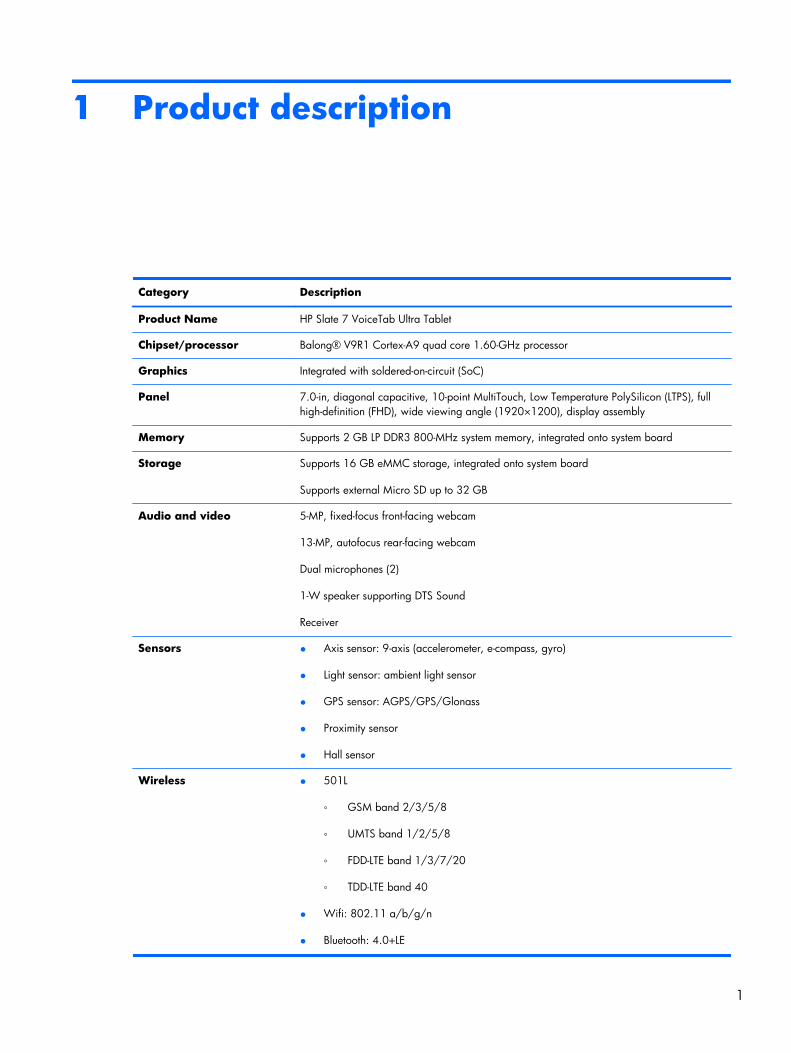
Category Description
Product Name HP Slate 7 VoiceTab Ultra Tablet
Chipset/processor Balong® V9R1 Cortex-A9 quad core 1.60-GHz processor
Graphics Integrated with soldered-on-circuit (SoC)
Panel 7.0-in, diagonal capacitive, 10-point MultiTouch, Low Temperature PolySilicon (LTPS), fullhigh-definition (FHD), wide viewing angle (1920×1200), display assembly
Memory Supports 2 GB LP DDR3 800-MHz system memory, integrated onto system board
Storage Supports 16 GB eMMC storage, integrated onto system board
Supports external Micro SD up to 32 GB
Audio and video 5-MP, fixed-focus front-facing webcam
13-MP, autofocus rear-facing webcam
Dual microphones (2)
1-W speaker supporting DTS Sound
Receiver
Sensors ● Axis sensor: 9-axis (accelerometer, e-compass, gyro)
● Light sensor: ambient light sensor
● GPS sensor: AGPS/GPS/Glonass
● Proximity sensor
● Hall sensor
Wireless ● 501L
◦ GSM band 2/3/5/8
◦ UMTS band 1/2/5/8
◦ FDD-LTE band 1/3/7/20
◦ TDD-LTE band 40
● Wifi: 802.11 a/b/g/n
● Bluetooth: 4.0+LE
1
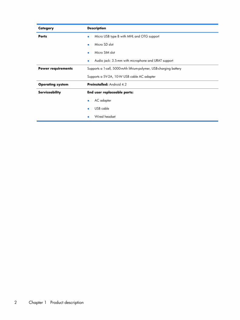
Category Description
Ports ● Micro USB type B with MHL and OTG support
● Micro SD slot
● Micro SIM slot
● Audio jack: 3.5-mm with microphone and URAT support
Power requirements Supports a 1-cell, 5000-mAh lithium-polymer, USB-charging battery
Supports a 5V-2A, 10-W USB cable AC adapter
Operating system Preinstalled: Android 4.2
Serviceability End user replaceable parts:
● AC adapter
● USB cable
● Wired headset
2 Chapter 1 Product description
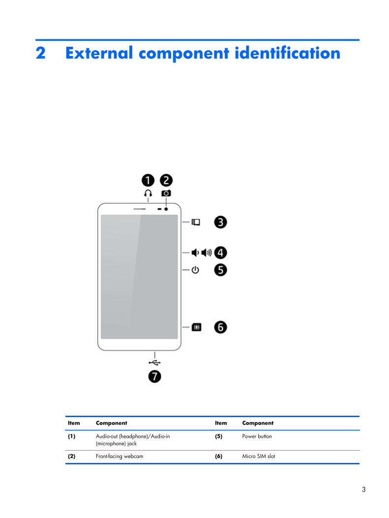
2 External component identification
Item Component Item Component
(1) Audio-out (headphone)/Audio-in(microphone) jack
(5) Power button
(2) Front-facing webcam (6) Micro SIM slot
3

Item Component Item Component
(3) Micro SD Card Reader slot (7) Micro USB 2.0 port
(4) Volume control button
4 Chapter 2 External component identification
3 Illustrated parts catalog
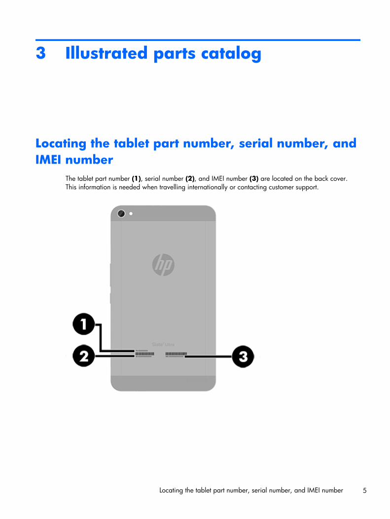
Locating the tablet part number, serial number, andIMEI number
The tablet part number (1), serial number (2), and IMEI number (3) are located on the back cover.This information is needed when travelling internationally or contacting customer support.
Locating the tablet part number, serial number, and IMEI number 5
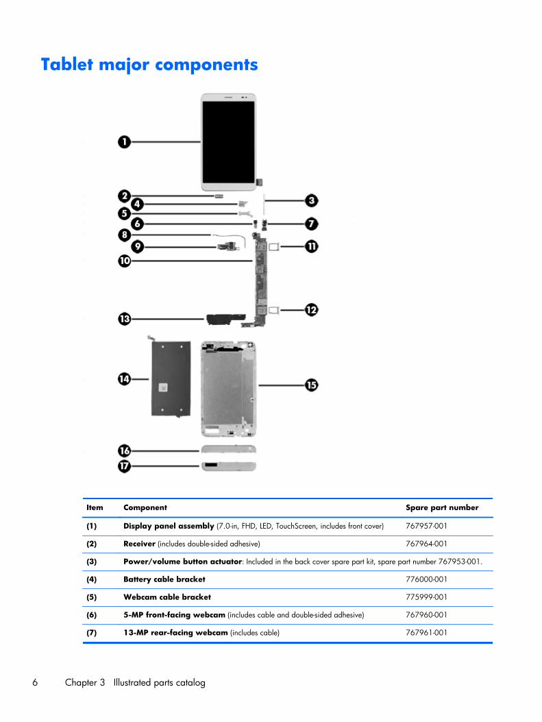
Tablet major components
Item Component Spare part number
(1) Display panel assembly (7.0-in, FHD, LED, TouchScreen, includes front cover) 767957-001
(2) Receiver (includes double-sided adhesive) 767964-001
(3) Power/volume button actuator: Included in the back cover spare part kit, spare part number 767953-001.
(4) Battery cable bracket 776000-001
(5) Webcam cable bracket 775999-001
(6) 5-MP front-facing webcam (includes cable and double-sided adhesive) 767960-001
(7) 13-MP rear-facing webcam (includes cable) 767961-001
6 Chapter 3 Illustrated parts catalog

Item Component Spare part number
(8) RF cable 776002-001
(9) I/O board (includes audio jack and cable) 767956-001
(10) System board equipped with a Balong V9R1 Cortex-A9 quad core 1.60-GHzprocessor, 2.0-GB of system memory, 16-GB eMMC system storage, and a graphicssubsystem with UMA memory
767959-001
(11) SD Card holder 775997-001
(12) SIM holder 775998-001
(13) Speaker 767958-001
(14) Battery, 1-cell, 5000-mAh, Li-ion, USB-charging (includes cable) 767954-001
(15) Back cover with battery (1-cell, 5000-mAh, Li-ion, USB-charging, includes cable andpower/volume board actuator)
767953-001
(16) Top cover 767962-001
(17) Bottom cover 767963-001
Miscellaneous parts
Component Spare part number
10-W AC adapter:
For use only in Europe and South Korea 773125-009
For use only in India 773125-005
For use only in Asia Pacific countries and regions, Japan, and North America 773125-008
For use only in South Africa 773125-007
For use only in the United Kingdom and Singapore 773125-003
Cable key 776001-001
Cover Hardware Kit 778550-001
Earphone 777776-001
HP Slate 7 VoiceTab Ultra Tablet:
HP Slate 7 VoiceTab Ultra Tablet for use in all countries and regions except Europe, the MiddleEast, and Africa (equipped with a Balong V9R1 Cortex-A9 quad core 1.60-GHz processor, 7.0-in, FHD, LED, TouchScreen, display panel assembly, 2.0-GB of system memory, 16-GB eMMCsystem storage, and a graphics subsystem with UMA memory)
767955-001
HP Slate 7 VoiceTab Ultra Tablet for use only in Europe, the Middle East, and Africa (equippedwith a Balong V9R1 Cortex-A9 quad core 1.60-GHz processor, 7.0-in, FHD, LED, TouchScreen,display panel assembly, 2.0-GB of system memory, 16-GB eMMC system storage, and a graphicssubsystem with UMA memory)
767955-021
Screw Kit 778241-001
Miscellaneous parts 7
Component Spare part number
USB extension cable 767952-001
USB dongle 780960-001
Sequential part number listing
Spare part number Description
767952-001 USB extension cable
767953-001 Back cover with battery (1-cell, 5000-mAh, Li-ion, USB-charging, includes cable and power/volumeboard actuator)
767954-001 Battery, 1-cell, 5000-mAh, Li-ion, USB-charging (includes cable)
767955-001 HP Slate 7 VoiceTab Ultra Tablet for use in all countries and regions except Europe, the MiddleEast, and Africa (equipped with a Balong V9R1 Cortex-A9 quad core 1.60-GHz processor, 7.0-in,FHD, LED, TouchScreen, display panel assembly, 2.0-GB of system memory, 16-GB eMMC systemstorage, and a graphics subsystem with UMA memory)
767955-021 HP Slate 7 VoiceTab Ultra Tablet for use only in Europe, the Middle East, and Africa (equippedwith a Balong V9R1 Cortex-A9 quad core 1.60-GHz processor, 7.0-in, FHD, LED, TouchScreen,display panel assembly, 2.0-GB of system memory, 16-GB eMMC system storage, and a graphicssubsystem with UMA memory)
767956-001 I/O board (includes audio jack and cable)
767957-001 7.0-in, FHD, LED, TouchScreen, display panel assembly (includes front cover)
767958-001 Speaker
767959-001 System board equipped with a Balong V9R1 Cortex-A9 quad core 1.60-GHz processor, 2.0-GB ofsystem memory, 16-GB eMMC system storage, and a graphics subsystem with UMA memory
767960-001 5-MP front-facing webcam (includes cable and double-sided adhesive)
767961-001 13-MP rear-facing webcam (includes cable)
767962-001 Top cover
767963-001 Bottom cover
767964-001 Receiver (includes double-sided adhesive)
773125-003 10-W AC adapter for use only in the United Kingdom and Singapore (includes plug)
773125-005 10-W AC adapter for use only in India (includes plug)
773125-007 10-W AC adapter for use only in South Africa (includes plug)
773125-008 10-W AC adapter for use only in Asia Pacific countries and regions, Japan, and North America(includes plug)
773125-009 10-W AC adapter for use only in Europe and South Korea (includes plug)
775997-001 SD Card holder
775998-001 SIM holder
8 Chapter 3 Illustrated parts catalog
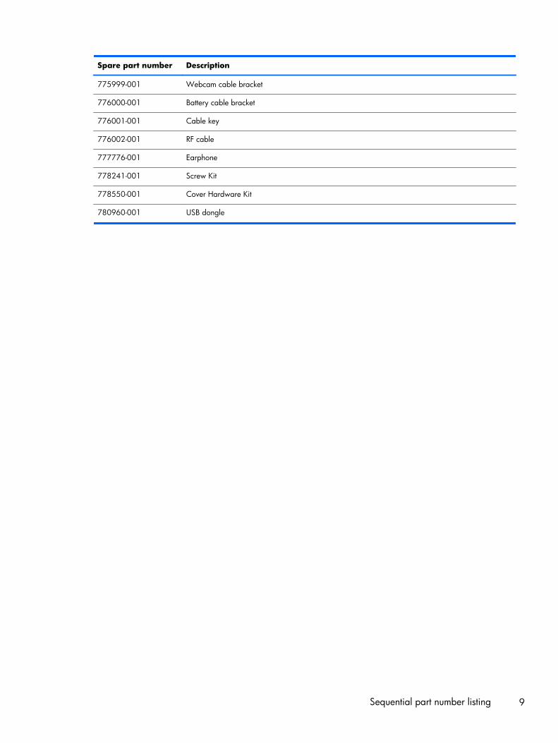
Spare part number Description
775999-001 Webcam cable bracket
776000-001 Battery cable bracket
776001-001 Cable key
776002-001 RF cable
777776-001 Earphone
778241-001 Screw Kit
778550-001 Cover Hardware Kit
780960-001 USB dongle
Sequential part number listing 9
4 Removal and replacementpreliminary requirements
Tools requiredYou will need the following tools to complete the removal and replacement procedures:
● Flat-bladed screw driver
● Magnetic screw driver
● Phillips P0 screw driver
● Phillips P00 screw driver
Service considerationsThe following sections include some of the considerations that must be kept in mind during disassemblyand assembly procedures.
NOTE: As each subassembly is removed from the tablet, place the subassembly (and allaccompanying screws) away from the work area to prevent damage.
Plastic parts
CAUTION: Using excessive force during disassembly and reassembly can damage plastic parts.Use care when handling the plastic parts. Apply pressure only at the points designated in themaintenance instructions.
Cables and connectors
CAUTION: When servicing the tablet, be sure that cables are placed in their proper locations duringthe reassembly process. Improper cable placement can damage the tablet.
Cables must be handled with extreme care to avoid damage. Apply only the tension required to unseator seat the cables during removal and insertion. Handle cables by the connector whenever possible. Inall cases, avoid bending, twisting, or tearing cables. Be sure that cables are routed in such a way thatthey cannot be caught or snagged by parts being removed or replaced. Handle flex cables withextreme care; these cables tear easily.
10 Chapter 4 Removal and replacement preliminary requirements

Drive handling
CAUTION: Drives are fragile components that must be handled with care. To prevent damage tothe tablet, damage to a drive, or loss of information, observe these precautions:
Before removing or inserting a drive, shut down the tablet. If you are unsure whether the tablet is off orin Hibernation, turn the tablet on, and then shut it down through the operating system.
Before handling a drive, be sure that you are discharged of static electricity. While handling a drive,avoid touching the connector.
Before removing a diskette drive or optical drive, be sure that a diskette or disc is not in the drive andbe sure that the optical drive tray is closed.
Handle drives on surfaces covered with at least one inch of shock-proof foam.
Avoid dropping drives from any height onto any surface.
After removing a drive, place it in a static-proof bag.
Avoid exposing a drive to products that have magnetic fields, such as monitors or speakers.
Avoid exposing a drive to temperature extremes or liquids.
If a drive must be mailed, place the drive in a bubble pack mailer or other suitable form of protectivepackaging and label the package “FRAGILE.”
Grounding guidelines
Electrostatic discharge damage
Electronic components are sensitive to electrostatic discharge (ESD). Circuitry design and structuredetermine the degree of sensitivity. Networks built into many integrated circuits provide someprotection, but in many cases, ESD contains enough power to alter device parameters or meltsilicon junctions.
A discharge of static electricity from a finger or other conductor can destroy static-sensitive devices ormicrocircuitry. Even if the spark is neither felt nor heard, damage may have occurred.
An electronic device exposed to ESD may not be affected at all and can work perfectly throughout anormal cycle. Or the device may function normally for a while, then degrade in the internal layers,reducing its life expectancy.
Grounding guidelines 11

CAUTION: To prevent damage to the tablet when you are removing or installing internalcomponents, observe these precautions:
Keep components in their electrostatic-safe containers until you are ready to install them.
Before touching an electronic component, discharge static electricity by using the guidelines describedin this section.
Avoid touching pins, leads, and circuitry. Handle electronic components as little as possible.
If you remove a component, place it in an electrostatic-safe container.
The following table shows how humidity affects the electrostatic voltage levels generated bydifferent activities.
CAUTION: A product can be degraded by as little as 700 V.
Typical electrostatic voltage levels
Relative humidity
Event 10% 40% 55%
Walking across carpet 35,000 V 15,000 V 7,500 V
Walking across vinyl floor 12,000 V 5,000 V 3,000 V
Motions of a bench worker 6,000 V 800 V 400 V
Removing DIPS from a plastic tube 2,000 V 700 V 400 V
Removing DIPS from a vinyl tray 11,500 V 4,000 V 2,000 V
Removing DIPS from Styrofoam 14,500 V 5,000 V 3,500 V
Removing bubble pack from PCB 26,500 V 20,000 V 7,000 V
Packing PCBs in a foam-lined box 21,000 V 11,000 V 5,000 V
12 Chapter 4 Removal and replacement preliminary requirements
Packaging and transporting guidelines
Follow these grounding guidelines when packaging and transporting equipment:
● To avoid hand contact, transport products in static-safe tubes, bags, or boxes.
● Protect ESD-sensitive parts and assemblies with conductive or approved containers or packaging.
● Keep ESD-sensitive parts in their containers until the parts arrive at static-free workstations.
● Place items on a grounded surface before removing items from their containers.
● Always be properly grounded when touching a component or assembly.
● Store reusable ESD-sensitive parts from assemblies in protective packaging or non-conductive foam.
● Use transporters and conveyors made of antistatic belts and roller bushings. Be sure thatmechanized equipment used for moving materials is wired to ground and that proper materialsare selected to avoid static charging. When grounding is not possible, use an ionizer to dissipateelectric charges.
Workstation guidelines
Follow these grounding workstation guidelines:
● Cover the workstation with approved static-shielding material.
● Use a wrist strap connected to a properly grounded work surface and use properly grounded toolsand equipment.
● Use conductive field service tools, such as cutters, screw drivers, and vacuums.
● When fixtures must directly contact dissipative surfaces, use fixtures made only of static-safe materials.
● Keep the work area free of non-conductive materials, such as ordinary plastic assembly aidsand Styrofoam.
● Handle ESD-sensitive components, parts, and assemblies by the case or PCM laminate. Handlethese items only at static-free workstations.
● Avoid contact with pins, leads, or circuitry.
● Turn off power and input signals before inserting or removing connectors or test equipment.
Grounding guidelines 13

Equipment guidelines
Grounding equipment must include either a wrist strap or a foot strap at a grounded workstation.
● When seated, wear a wrist strap connected to a grounded system. Wrist straps are flexible strapswith a minimum of one megohm ±10% resistance in the ground cords. To provide proper ground,wear a strap snugly against the skin at all times. On grounded mats with banana-plug connectors,use alligator clips to connect a wrist strap.
● When standing, use foot straps and a grounded floor mat. Foot straps (heel, toe, or boot straps)can be used at standing workstations and are compatible with most types of shoes or boots. Onconductive floors or dissipative floor mats, use foot straps on both feet with a minimum of onemegohm resistance between the operator and ground. To be effective, the conductive must beworn in contact with the skin.
The following grounding equipment is recommended to prevent electrostatic damage:
● Antistatic tape
● Antistatic smocks, aprons, and sleeve protectors
● Conductive bins and other assembly or soldering aids
● Non-conductive foam
● Conductive countertop workstations with ground cords of one megohm resistance
● Static-dissipative tables or floor mats with hard ties to the ground
● Field service kits
● Static awareness labels
● Material-handling packages
● Non-conductive plastic bags, tubes, or boxes
● Metal tote boxes
● Electrostatic voltage levels and protective materials
The following table lists the shielding protection provided by antistatic bags and floor mats.
Material Use Voltage protection level
Antistatic plastics Bags 1,500 V
Carbon-loaded plastic Floor mats 7,500 V
Metallized laminate Floor mats 5,000 V
14 Chapter 4 Removal and replacement preliminary requirements
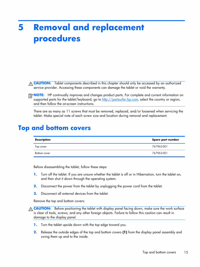
5 Removal and replacementprocedures
CAUTION: Tablet components described in this chapter should only be accessed by an authorizedservice provider. Accessing these components can damage the tablet or void the warranty.
NOTE: HP continually improves and changes product parts. For complete and current information onsupported parts for the tablet/keyboard, go to http://partsurfer.hp.com, select the country or region,and then follow the on-screen instructions.
There are as many as 11 screws that must be removed, replaced, and/or loosened when servicing thetablet. Make special note of each screw size and location during removal and replacement.
Top and bottom covers
Description Spare part number
Top cover 767962-001
Bottom cover 767963-001
Before disassembling the tablet, follow these steps:
1. Turn off the tablet. If you are unsure whether the tablet is off or in Hibernation, turn the tablet on,and then shut it down through the operating system.
2. Disconnect the power from the tablet by unplugging the power cord from the tablet.
3. Disconnect all external devices from the tablet.
Remove the top and bottom covers:
CAUTION: Before positioning the tablet with display panel facing down, make sure the work surfaceis clear of tools, screws, and any other foreign objects. Failure to follow this caution can result indamage to the display panel.
1. Turn the tablet upside down with the top edge toward you.
2. Release the outside edges of the top and bottom covers (1) from the display panel assembly andswing them up and to the inside.
Top and bottom covers 15

3. Remove the top and bottom covers (2).
Reverse this procedure to install the top and bottom covers.
Back cover
Description Spare part number
Back cover with battery (1-cell, 5000-mAh, Li-ion, USB-charging, includes cable and power/volume board actuator)
767953-001
Display panel assembly (7.0-in, FHD, LED, TouchScreen, includes front cover) 767957-001
Before removing the back cover, follow these steps:
1. Turn off the tablet. If you are unsure whether the tablet is off or in Hibernation, turn the tablet on,and then shut it down through the operating system.
2. Disconnect the power from the tablet by unplugging the power cord from the tablet.
3. Disconnect all external devices from the tablet.
4. Remove the top and bottom covers (see Top and bottom covers on page 15).
Remove the back cover:
16 Chapter 5 Removal and replacement procedures
CAUTION: Before positioning the tablet with display panel facing down, make sure the work surfaceis clear of tools, screws, and any other foreign objects. Failure to follow this caution can result indamage to the display panel.
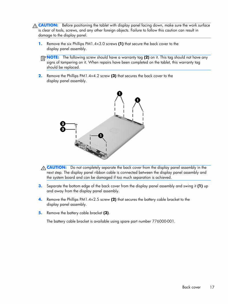
1. Remove the six Phillips PM1.4×3.0 screws (1) that secure the back cover to thedisplay panel assembly.
NOTE: The following screw should have a warranty tag (2) on it. This tag should not have anysigns of tampering on it. When repairs have been completed on the tablet, this warranty tagshould be replaced.
2. Remove the Phillips PM1.4×4.2 screw (3) that secures the back cover to thedisplay panel assembly.
CAUTION: Do not completely separate the back cover from the display panel assembly in thenext step. The display panel ribbon cable is connected between the display panel assembly andthe system board and can be damaged if too much separation is achieved.
3. Separate the bottom edge of the back cover from the display panel assembly and swing it (1) upand away from the display panel assembly.
4. Remove the Phillips PM1.4×2.5 screw (2) that secures the battery cable bracket to thedisplay panel assembly.
5. Remove the battery cable bracket (3).
The battery cable bracket is available using spare part number 776000-001.
Back cover 17
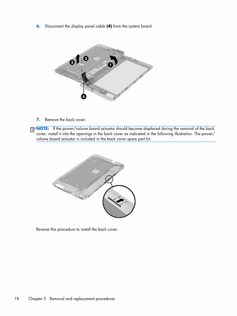
6. Disconnect the display panel cable (4) from the system board.
7. Remove the back cover.
NOTE: If the power/volume board actuator should become displaced during the removal of the backcover, install it into the openings in the back cover as indicated in the following illustration. The power/volume board actuator is included in the back cover spare part kit.
Reverse this procedure to install the back cover.
18 Chapter 5 Removal and replacement procedures

Receiver
Description Spare part number
Receiver (includes double-sided adhesive) 767964-001
Before removing the receiver, follow these steps:
1. Turn off the tablet. If you are unsure whether the tablet is off or in Hibernation, turn the tablet on,and then shut it down through the operating system.
2. Disconnect the power from the tablet by unplugging the power cord from the tablet.
3. Disconnect all external devices from the tablet.
4. Remove the top and bottom covers (see Top and bottom covers on page 15).
5. Remove the back cover (see Back cover on page 16).
Remove the receiver:
▲ Detach the receiver from the display panel assembly. (The receiver is attached to the display panelassembly with double-sided adhesive.)
Reverse this procedure to install the receiver.
Receiver 19

Battery
Description Spare part number
1-cell, 5000-mAh, Li-ion, USB-charging battery (includes cable) 767954-001
Before removing the battery, follow these steps:
1. Turn off the tablet. If you are unsure whether the tablet is off or in Hibernation, turn the tablet on,and then shut it down through the operating system.
2. Disconnect the power from the tablet by unplugging the power cord from the tablet.
3. Disconnect all external devices from the tablet.
4. Remove the top and bottom covers (see Top and bottom covers on page 15).
5. Remove the back cover (see Back cover on page 16).
WARNING! To reduce potential safety issues, use only the battery provided with the tablet, areplacement battery provided by HP, or a compatible battery purchased from HP.
CAUTION: Removing a battery that is the sole power source for the tablet can cause loss ofinformation. To prevent loss of information, save your work or shut down the tablet through theoperating system before removing the battery.
Remove the battery:
1. Disconnect the battery cable (1) from the system board.
2. Detach the three sections of grounding tape (2) that secure the battery to the back cover.
3. Remove the battery (3).
Reverse this procedure to install the battery.
20 Chapter 5 Removal and replacement procedures
RF cable
Description Spare part number
RF cable 776002-001
Before removing the RF cable, follow these steps:
1. Turn off the tablet. If you are unsure whether the tablet is off or in Hibernation, turn the tablet on,and then shut it down through the operating system.
2. Disconnect the power from the tablet by unplugging the power cord from the tablet.
3. Disconnect all external devices from the tablet.
4. Remove the top and bottom covers (see Top and bottom covers on page 15).
5. Remove the back cover (see Back cover on page 16).
6. Disconnect the battery cable from the system board (see Battery on page 20).
Remove the RF cable:
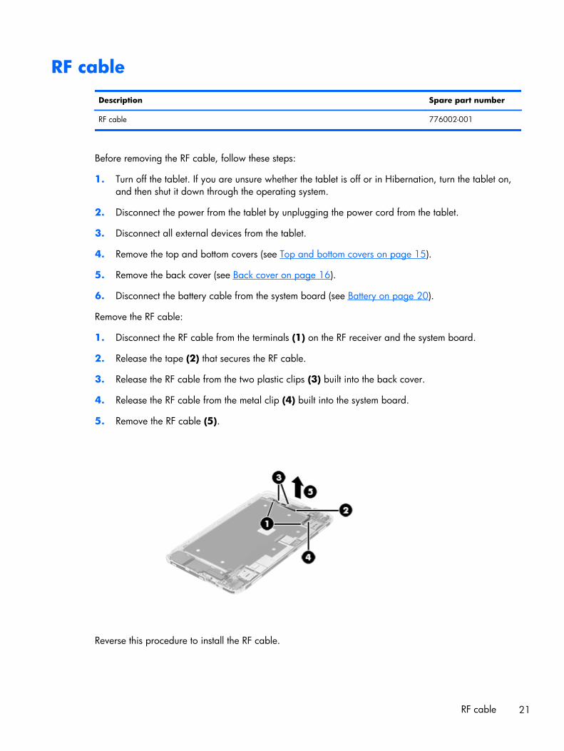
1. Disconnect the RF cable from the terminals (1) on the RF receiver and the system board.
2. Release the tape (2) that secures the RF cable.
3. Release the RF cable from the two plastic clips (3) built into the back cover.
4. Release the RF cable from the metal clip (4) built into the system board.
5. Remove the RF cable (5).
Reverse this procedure to install the RF cable.
RF cable 21
Webcam cable bracket
Description Spare part number
Webcam cable bracket 775999-001
Before removing the webcam cable bracket, follow these steps:
1. Turn off the tablet. If you are unsure whether the tablet is off or in Hibernation, turn the tablet on,and then shut it down through the operating system.
2. Disconnect the power from the tablet by unplugging the power cord from the tablet.
3. Disconnect all external devices from the tablet.
4. Remove the top and bottom covers (see Top and bottom covers on page 15).
5. Remove the back cover (see Back cover on page 16).
6. Disconnect the battery cable from the system board (see Battery on page 20).
Remove the webcam cable bracket:
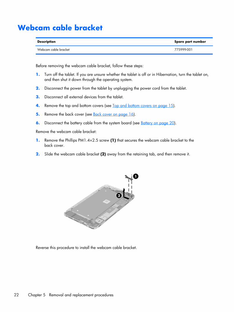
1. Remove the Phillips PM1.4×2.5 screw (1) that secures the webcam cable bracket to theback cover.
2. Slide the webcam cable bracket (2) away from the retaining tab, and then remove it.
Reverse this procedure to install the webcam cable bracket.
22 Chapter 5 Removal and replacement procedures

I/O board
Description Spare part number
I/O board (includes audio jack and cable) 767956-001
Before removing the I/O board, follow these steps:
1. Turn off the tablet. If you are unsure whether the tablet is off or in Hibernation, turn the tablet on,and then shut it down through the operating system.
2. Disconnect the power from the tablet by unplugging the power cord from the tablet.
3. Disconnect all external devices from the tablet.
4. Remove the top and bottom covers (see Top and bottom covers on page 15).
5. Remove the back cover (see Back cover on page 16).
6. Disconnect the battery cable from the system board (see Battery on page 20).
7. Remove the webcam cable bracket (see Webcam cable bracket on page 22).
Remove the I/O board:
1. Remove the Phillips PM1.4×2.5 screw (1) that secures the I/O board to the back cover.
2. Disconnect the I/O board cable (2) from the system board.
3. Remove the I/O board (3).
Reverse this procedure to install the I/O board.
I/O board 23

Front-facing webcam
Description Spare part number
5.0-MP front-facing webcam (includes cable and double-sided adhesive) 767960-001
Before removing the front-facing webcam, follow these steps:
1. Turn off the tablet. If you are unsure whether the tablet is off or in Hibernation, turn the tablet on,and then shut it down through the operating system.
2. Disconnect the power from the tablet by unplugging the power cord from the tablet.
3. Disconnect all external devices from the tablet.
4. Remove the top and bottom covers (see Top and bottom covers on page 15).
5. Remove the back cover (see Back cover on page 16).
6. Disconnect the battery cable from the system board (see Battery on page 20).
7. Remove the webcam cable bracket (see Webcam cable bracket on page 22).
Remove the front-facing webcam:
1. Disconnect the front-facing webcam cable (1) from the system board.
2. Detach the front-facing webcam (2) from the back cover. (The front-facing webcam is attached tothe back cover with double-sided adhesive.)
3. Remove the front-facing webcam and cable.
Reverse this procedure to install the front-facing webcam.
24 Chapter 5 Removal and replacement procedures

Rear-facing webcam
Description Spare part number
13.0-MP rear-facing webcam (includes cable) 767961-001
Before removing the rear-facing webcam, follow these steps:
1. Turn off the tablet. If you are unsure whether the tablet is off or in Hibernation, turn the tablet on,and then shut it down through the operating system.
2. Disconnect the power from the tablet by unplugging the power cord from the tablet.
3. Disconnect all external devices from the tablet.
4. Remove the top and bottom covers (see Top and bottom covers on page 15).
5. Remove the back cover (see Back cover on page 16).
6. Disconnect the battery cable from the system board (see Battery on page 20).
7. Remove the webcam cable bracket (see Webcam cable bracket on page 22).
Remove the rear-facing webcam:
1. Disconnect the rear-facing webcam cable (1) from the system board.
2. Remove the rear-facing webcam (2) and cable.
Reverse this procedure to install the rear-facing webcam.
Rear-facing webcam 25
Speaker
Description Spare part number
Speaker 767958-001
Before removing the speaker, follow these steps:
1. Turn off the tablet. If you are unsure whether the tablet is off or in Hibernation, turn the tablet on,and then shut it down through the operating system.
2. Disconnect the power from the tablet by unplugging the power cord from the tablet.
3. Disconnect all external devices from the tablet.
4. Remove the top and bottom covers (see Top and bottom covers on page 15).
5. Remove the back cover (see Back cover on page 16).
6. Disconnect the battery cable from the system board (see Battery on page 20).
7. Remove the webcam cable bracket (see Webcam cable bracket on page 22).
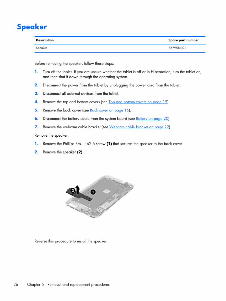
Remove the speaker:
1. Remove the Phillips PM1.4×2.5 screw (1) that secures the speaker to the back cover.
2. Remove the speaker (2).
Reverse this procedure to install the speaker.
26 Chapter 5 Removal and replacement procedures
System board
Description Spare part number
System board equipped with a Balong V9R1 Cortex-A9 quad core 1.60-GHz processor, 2.0-GBof system memory, 16-GB eMMC system storage, and a graphics subsystem with UMA memory
767959-001
Before removing the system board, follow these steps:
1. Turn off the tablet. If you are unsure whether the tablet is off or in Hibernation, turn the tablet on,and then shut it down through the operating system.
2. Disconnect the power from the tablet by unplugging the power cord from the tablet.
3. Disconnect all external devices from the tablet.
4. Remove the top and bottom covers (see Top and bottom covers on page 15).
5. Remove the back cover (see Back cover on page 16).
6. Disconnect the battery cable from the system board (see Battery on page 20).
7. Remove the webcam cable bracket (see Webcam cable bracket on page 22).
8. Remove the speaker (see Speaker on page 26).
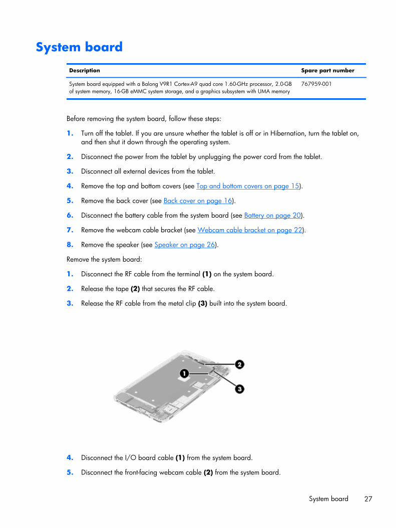
Remove the system board:
1. Disconnect the RF cable from the terminal (1) on the system board.
2. Release the tape (2) that secures the RF cable.
3. Release the RF cable from the metal clip (3) built into the system board.
4. Disconnect the I/O board cable (1) from the system board.
5. Disconnect the front-facing webcam cable (2) from the system board.
System board 27
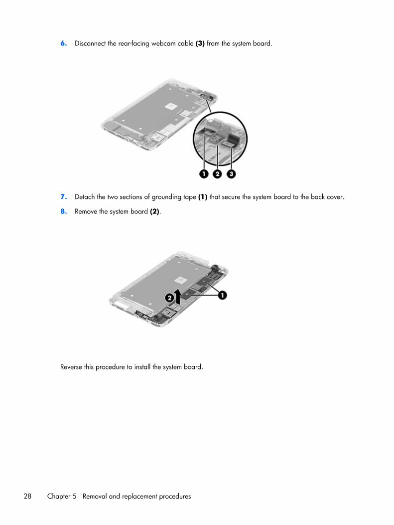
6. Disconnect the rear-facing webcam cable (3) from the system board.
7. Detach the two sections of grounding tape (1) that secure the system board to the back cover.
8. Remove the system board (2).
Reverse this procedure to install the system board.
28 Chapter 5 Removal and replacement procedures

6 Backing up and recovering data
Updating apps, widgets, and the operating systemHP recommends that all apps, widgets, and the operating system be updated on a regular basis to thelatest versions. Updates can resolve issues and bring new features and options to the tablet. Technologyis always changing, and updating apps, widgets, and the operating system allows the tablet to run thelatest technology available. For example, older apps and widgets might not work well with the mostrecent operating system.
Go to the Google Play store to download the latest versions of HP and third-party apps and widgets.The operating system will download system updates automatically and provide notification when it isready to install these updates. To update the operating system manually, go to http://www.hp.com/support.
Back up and resetTo select preferences for backing up and restoring data in case of loss:
1. Touch .
2. Under PRIVACY & SECURITY, touch Back up & reset.
3. Under BACKUP & RESTORE, select one or more of the following:
● Back up my data—Select the check box to enable backing up app data, Wi-Fipasswords, and other settings to Google servers, or clear the check box to disablethis feature.
● Backup account—Select a Google account for backing up data.
● Automatic restore—Select the check box to enable backed up settings and data to berestored when an app is reinstalled, or clear the check box to disable this feature.
Updating apps, widgets, and the operating system 29
Factory data resetCAUTION: If this option is selected, all settings are reset to factory values, and all personal data onthe device is deleted.
To reset all settings and delete all data on the device:
1. Touch .
2. Under PRIVACY & SECURITY, touch Back up & reset.
3. Under PERSONAL DATA, select Factory data reset, and then follow the on-screeninstructions.
30 Chapter 6 Backing up and recovering data
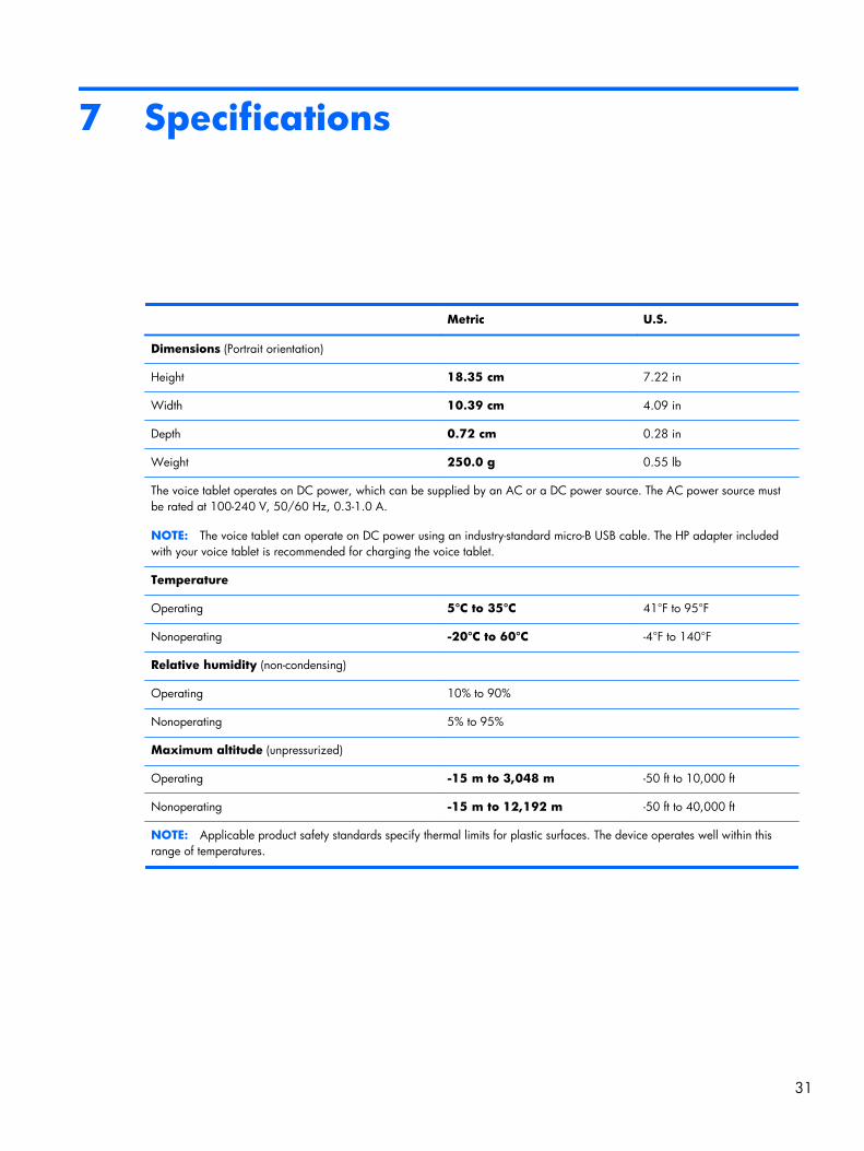
7 Specifications
Metric U.S.
Dimensions (Portrait orientation)
Height 18.35 cm 7.22 in
Width 10.39 cm 4.09 in
Depth 0.72 cm 0.28 in
Weight 250.0 g 0.55 lb
The voice tablet operates on DC power, which can be supplied by an AC or a DC power source. The AC power source mustbe rated at 100-240 V, 50/60 Hz, 0.3-1.0 A.
NOTE: The voice tablet can operate on DC power using an industry-standard micro-B USB cable. The HP adapter includedwith your voice tablet is recommended for charging the voice tablet.
Temperature
Operating 5°C to 35°C 41°F to 95°F
Nonoperating -20°C to 60°C -4°F to 140°F
Relative humidity (non-condensing)
Operating 10% to 90%
Nonoperating 5% to 95%
Maximum altitude (unpressurized)
Operating -15 m to 3,048 m -50 ft to 10,000 ft
Nonoperating -15 m to 12,192 m -50 ft to 40,000 ft
NOTE: Applicable product safety standards specify thermal limits for plastic surfaces. The device operates well within thisrange of temperatures.
31

8 Power cord set requirements
The wide-range input feature of the tablet permits it to operate from any line voltage from 100 to 120volts AC, or from 220 to 240 volts AC.
The 3-conductor power cord set included with the tablet meets the requirements for use in the country orregion where the equipment is purchased.
Power cord sets for use in other countries and regions must meet the requirements of the country orregion where the tablet is used.
Requirements for all countriesThe following requirements are applicable to all countries and regions:
● The length of the power cord set must be at least 1.0 m (3.3 ft) and no more than 2.0 m (6.5 ft).
● All power cord sets must be approved by an acceptable accredited agency responsible forevaluation in the country or region where the power cord set will be used.
● The power cord sets must have a minimum current capacity of 10 amps and a nominal voltagerating of 125 or 250 V AC, as required by the power system of each country or region.
● The appliance coupler must meet the mechanical configuration of an EN 60 320/IEC 320Standard Sheet C13 connector for mating with the appliance inlet on the back of the tablet.
Requirements for specific countries and regions
Country/region Accredited agency Applicable note number
Australia EANSW 1
Austria OVE 1
Belgium CEBC 1
Canada CSA 2
Denmark DEMKO 1
Finland FIMKO 1
France UTE 1
32 Chapter 8 Power cord set requirements
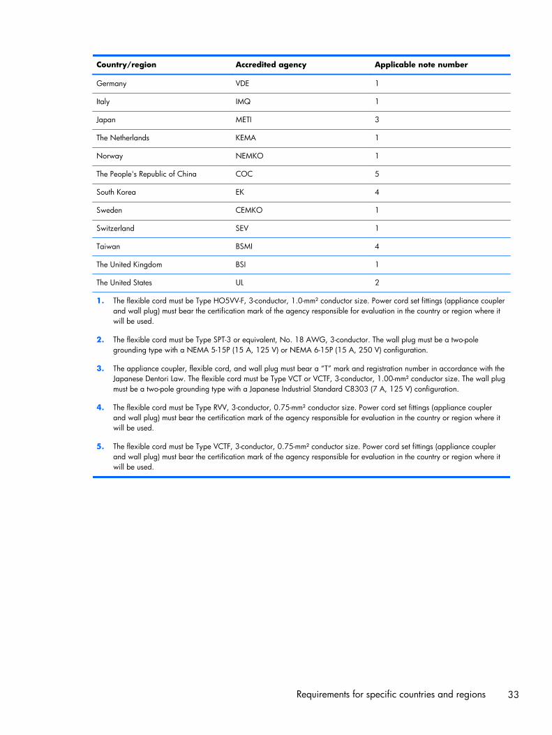
Country/region Accredited agency Applicable note number
Germany VDE 1
Italy IMQ 1
Japan METI 3
The Netherlands KEMA 1
Norway NEMKO 1
The People's Republic of China COC 5
South Korea EK 4
Sweden CEMKO 1
Switzerland SEV 1
Taiwan BSMI 4
The United Kingdom BSI 1
The United States UL 2
1. The flexible cord must be Type HO5VV-F, 3-conductor, 1.0-mm² conductor size. Power cord set fittings (appliance couplerand wall plug) must bear the certification mark of the agency responsible for evaluation in the country or region where itwill be used.
2. The flexible cord must be Type SPT-3 or equivalent, No. 18 AWG, 3-conductor. The wall plug must be a two-polegrounding type with a NEMA 5-15P (15 A, 125 V) or NEMA 6-15P (15 A, 250 V) configuration.
3. The appliance coupler, flexible cord, and wall plug must bear a “T” mark and registration number in accordance with theJapanese Dentori Law. The flexible cord must be Type VCT or VCTF, 3-conductor, 1.00-mm² conductor size. The wall plugmust be a two-pole grounding type with a Japanese Industrial Standard C8303 (7 A, 125 V) configuration.
4. The flexible cord must be Type RVV, 3-conductor, 0.75-mm² conductor size. Power cord set fittings (appliance couplerand wall plug) must bear the certification mark of the agency responsible for evaluation in the country or region where itwill be used.
5. The flexible cord must be Type VCTF, 3-conductor, 0.75-mm² conductor size. Power cord set fittings (appliance couplerand wall plug) must bear the certification mark of the agency responsible for evaluation in the country or region where itwill be used.
Requirements for specific countries and regions 33
9 Recycling
When a non-rechargeable or rechargeable battery has reached the end of its useful life, do not disposeof the battery in general household waste. Follow the local laws and regulations in your area forbattery disposal.
HP encourages customers to recycle used electronic hardware, HP original print cartridges, andrechargeable batteries. For more information about recycling programs, see the HP Web site athttp://www.hp.com/recycle.
34 Chapter 9 Recycling
Index
AAC adapter, spare part numbers
8audio, product description 1audio-in jack 3audio-out jack 3
Bback cover
removal 16spare part number 7, 8, 16
batteryremoval 20spare part number 7, 8, 20
battery cable bracketremoval 17spare part number 6, 9, 17
bottom coverremoval 15spare part number 7, 8, 15
buttonspower 3volume control 4
Ccable key, spare part number 7,
9cables, service considerations 10chipset, product description 1connectors, service
considerations 10Cover Hardware Kit, spare part
number 7, 9
Ddisplay panel assembly, spare part
number 6, 8display panel, product
description 1
drivesprecautions 11preventing damage 11
Eearphone, spare part number 7,
9electrostatic discharge 11equipment guidelines 14
Ffront-facing webcam
location 3removal 24spare part number 6, 8, 24
Ggraphics, product description 1grounding guidelines 11guidelines
equipment 14grounding 11packaging 13transporting 13workstation 13
Hheadphone jack 3
II/O board
removal 23spare part number 7, 8, 23
Jjacks
audio-in 3audio-out 3
headphone 3microphone 3
Mmemory, product description 1microphone jack 3microphone, product description
1model name 1
Ooperating system, product
description 2
Ppackaging guidelines 13plastic parts, service
considerations 10ports
product description 2USB 4
power adapter, spare partnumbers 7
power button 3power cord, set requirements 32power requirements, product
description 2processor, product description 1product description
audio 1chipset 1display panel 1graphics 1memory 1microphone 1operating system 2ports 2power requirements 2processors 1
Index 35
product name 1sensors 1serviceability 2storage 1video 1wireless 1
product name 1
Rrear-facing webcam
removal 25spare part number 6, 8, 25
receiverremoval 19spare part number 6, 8, 19
RF cableremoval 21spare part number 7, 9, 21
SScrew Kit, spare part number 7, 9SD Card holder, spare part
number 7, 8SD Card Reader slot 4sensors, product description 1service considerations
cables 10connectors 10plastic parts 10
serviceability, product description2
SIM holder, spare part number 7,8
SIM slot 3speaker
removal 26spare part number 7, 8, 26
storage, product description 1system board
removal 27spare part number 7, 8, 27
Ttablet
major components 6spare part numbers 7, 8specifications 31
top coverremoval 15spare part number 7, 8, 15
transporting guidelines 13
UUSB dongle, spare part number
8, 9USB extension cable, spare part
number 8USB port 4
Vvideo, product description 1volume control button 4
Wwebcam
removal 24, 25spare part numbers 6, 8, 24,
25webcam cable bracket
removal 22spare part number 6, 9, 22
wireless, product description 1workstation guidelines 13
36 Index