hp msm710 controllers installation...
TRANSCRIPT

HP MSM710 Controllers Installation Guide
AbstractThis document describes how to install and initially configure the MSM710 Controllers. This information applies to the MSM710Access Controller (J9328A) and the MSM710 Mobility Controller (J9325A). These products are hereafter referred to ascontroller. See also the MSM7xx Controllers Configuration Guide.
HP Part Number: 5998-1423Published: December 2011Edition: 1

© Copyright 2011 Hewlett-Packard Development Company, L.P.
The information contained herein is subject to change without notice. The only warranties for HP products and services are set forth in the expresswarranty statements accompanying such products and services. Nothing herein should be construed as constituting an additional warranty. HP shallnot be liable for technical or editorial errors or omissions contained herein.
Acknowledgments
Microsoft® and Windows®, are U.S. registered trademarks of Microsoft Corporation.

Contents1 Preparing for installation.............................................................................4
Package contents......................................................................................................................4Identifying controller components................................................................................................4Important installation prerequisites..............................................................................................5Powering the controller..............................................................................................................6
2 Installing...................................................................................................7Mounting in a rack...................................................................................................................7Mounting directly on a wall.......................................................................................................7
3 Controller initial configuration......................................................................8Perform initial configuration........................................................................................................8Verify guest access (optional) ..................................................................................................10
4 Working with controlled APs......................................................................15Verify AP discovery.................................................................................................................15Test the wireless public access network......................................................................................15
5 Support and other resources......................................................................16Online Documentation.............................................................................................................16Contacting HP........................................................................................................................16HP Websites..........................................................................................................................16Typographic conventions.........................................................................................................16
A Safety and EMC regulatory statements........................................................17Safety information..................................................................................................................17Informations concernant la sécurité...........................................................................................17Hinweise zur Sicherheit...........................................................................................................18Considerazioni sulla sicurezza.................................................................................................18Consideraciones sobre seguridad.............................................................................................19Safety information (Japan).......................................................................................................20Safety information (China).......................................................................................................21EMC Regulatory Statements.....................................................................................................21
B Recycle statements....................................................................................24Waste Electrical and Electronic Equipment (WEEE) statements......................................................24
Contents 3

1 Preparing for installationPackage contents
• Controller
• Power supply
• Self-adhesive rubber feet
• Documentation
Identifying controller componentsThe following figures show the various controls and connectors on the controller.
1 2 3 4 5
Controller rear panel
4: Internet port1: Power
5: Console port2: Reset button
3: LAN port
1 32
Controller front panel
1: Power LED
2: LAN port LED
3: Internet port LED
LAN port and Internet portThe controller has two auto-sensing 10/100/1000 Ethernet ports, each with a correspondingstatus light on the front panel. The LAN port supports Power over Ethernet (PoE) 802.3af, enablingthe controller to be powered by a PoE switch or PoE power injector.
Reset buttonPress and quickly release the button to reset the controller. This button can also be used to resetthe controller to factory defaults. See Resetting to factory defaults in the MSM7xx ControllersConfiguration Guide.
4 Preparing for installation

Console portThe controller console port is a standard serial port with DB-9 connector. To connect to a computer,use a standard (straight-through) serial cable (male-to-female). For pin-out details, see theMSM7xxControllers Configuration Guide.
Table 1 LEDs
DescriptionStateLED
The controller has no power.OffPower
The controller is starting up. If the power LED continues to blinkfor several Blinking minutes, it indicates that the software failed
Blinking
to load. Reset or power cycle the controller. If this conditionpersists, contact HP Support.
The controller is fully operational.On
Port is not connected or there is no activity.OffEthernet: LAN and Internet
Transmit/receive activity.Blinking
Stays on for a short period when the link is established.On
Important installation prerequisitesIMPORTANT: Make sure you read the following information before installing the controller.
Professional installation requiredPrior to installing or using this device, consult with a professional installer trained in RF installationand knowledgeable in local regulations including building and wiring codes, safety, channel,power, indoor/outdoor restrictions, and license requirements for the intended country. It is theresponsibility of the end user to ensure that installation and use comply with local safety and radioregulations.
CablingYou must use the appropriate cables, and where applicable, surge protection, for your givenregion. For compliance with EN55022 Class-B emissions requirement, use shielded Ethernet cables.
Country of useSome versions of the unit require the installer to select the country of operation during set up. Oncethe country has been set, the unit will automatically limit the available wireless channels, ensuringcompliant operation in the selected country. Incorrectly entering the country may result in illegaloperation and may cause harmful interference to other systems.
SafetyTake note of the following safety information during installation.
• If your network covers an area served by more than one power distribution system, be sureall safety grounds are securely interconnected.
• Network cables may occasionally be subject to hazardous transient voltages (caused bylightning or disturbances in the electrical power grid).
• Handle exposed metal components of the network with caution.
Important installation prerequisites 5

• This product does not have a power switch. It is powered-on when the LAN port is connectedto the external power supply is plugged into a PoE power source.
• This product and all interconnected equipment must be installed indoors within the samebuilding (except for outdoor models), including all PoE-powered network connections asdescribed by Environment A of the IEEE 802.3af standard.
Powering the controllerThe controller can be powered by:• The provided 48-volt power supply.
• A 10/100 or 10/100/1000 PoE-enabled switch. Various PoE-enabled switches are availablefrom HP.
• An HP PoE 1-Port Power Injector (J9407A).
CAUTION: If the controller will be powered by a user-supplied PoE power injector, use only agigabit-compatible power injector. Although 10/100 PoE-enabled switches are compatible, PoEinjectors designed for 10/100 networks only are NOT compatible with the AP.
6 Preparing for installation

2 Installing
WARNING! This is a general procedure. It is the installer’s responsibility to perform the installationin accordance with local electrical code and regulations.
It is recommended that you mount the controller only after performing the procedures in this guideand familiarizing yourself with the product.
• For table-top installations, attach the rubber feet to the bottom corners.
• For rack or wall mounting, you can order the optional part: HP MSM710 Controller RackMounting Kit, part number J9404A.
Mounting in a rackFor standard 48 cm (19-inch) rack mounting first attach a mounting bracket to each side of thecontroller using the provided screws, and then mount it in the rack.
Mounting directly on a wallAttach the controller to a wall so that the front faceplate (with status lights) faces the ceiling, theEthernet ports face the floor, and the top of the unit is flat against the wall. Do this as follows:1. Rotate the mounting bracket 90 degrees (from how it is used for rack mounting) and attach it
to the two screw holes along the bottom edge of the controller.
2. Drill holes in the wall and insert appropriate wall anchors (not supplied) according to theirdirections. The anchors must support at least 2.2 kg (5 pounds). Allow extra weight for cables.
3. Fasten the controller to the wall anchors using the screws supplied with the anchors. If needed,use washers on top of the bracket.
Mounting in a rack 7

3 Controller initial configurationThis procedure describes how to perform the initial configuration of a factory-default controller,enabling you to establish a wired connection through the controller to the Internet.The controller is managed via its Web-based management tool using Microsoft Internet Explorer8+ or Mozilla Firefox 3+.
Perform initial configurationNOTE: Because the provided power supply is the recommended way of powering the controller,it is the assumed powering method in all procedures in this guide.Do not connect power or network cables to the controller until directed to do so in this procedure.If cables are connected, temporarily disconnect them.
To initially configure the controller:1. Configure your computer to use a static IP address in the range 192.168.1.2 to 192.168.1.254
and set the subnet mask to 255.255.255.0. Set the default gateway to 192.168.1.1 and DNSserver to 192.168.1.1.
2. Connect network cables as follows:a. Disconnect any cable from the LAN port on your computer, and disable any wireless
connection.b. Connect the controller LAN port to the LAN port on your computer.c. Connect the controller Internet port to a network with Internet access or to the PC port of
a DSL modem or equivalent.3. Power on the controller and wait approximately 90 seconds until the Power LED stops blinking.4. Perform initial login tasks:
a. Using Microsoft Internet Explorer 8+ or Mozilla Firefox 3+, open page:https://192.168.1.1.
b. A security certificate warning may be displayed the first time you connect to themanagement tool. This is normal. Select whatever option is needed in your Web browserto continue to the management tool.
c. On the Login page, enter admin for Username and admin for Password and then selectLogin.
d. On the HP End User License Agreement page, read the agreement and then select AcceptHP End User License Agreement.
e. On the product registration page it is recommended that you register your product nowby selecting Register Now. If the controller is not connected to the Internet or you prefernot to register now, select Register Later. Registration is available at any time by selectingMaintenance > Registration.
f. In some regions, a Country prompt appears. Choose the country in which this productwill be used and select Save.
CAUTION: To maintain regulatory compliance, the country must be set accurately tothe country in which the controller and any controlled access points (APs) will operate.
g. At the Administrator password prompt it is recommended that you change the password.Select Save to save the new password or Cancel if you choose to keep the defaultpassword.
8 Controller initial configuration

5. Follow the Configure initial controller settings workflow.
a. It is highly recommended that you follow the Configure initial controller settings workflow.This workflow is selected by default. Select Start to launch this workflow. If you choosenot to run a workflow at this time, select the Home button to exit the workflow page.
b. The Configure initial controller settings workflow provides instructions and prompts youfor options. Read the instructions and respond to the prompts as desired, selecting Nextto get to the next workflow page. Context-sensitive online help is also available for eachpage of the workflow.
c. The last page in the workflow lists all configuration settings that will be applied. Forexample:
Perform initial configuration 9

Review the settings before you select Apply to save and activate the new configurationon the controller. Alternatively, select Back to go to the previous workflow page or selectCancel to discard your workflow settings and exit the workflow.
d. After applying your changes, a confirmation page appears showing the menu paths toeach configuration page associated with the Configure initial controller settings workflow.For example:
e. If desired, select a page link to make additional configuration changes and then selectAutomated workflows above the Network Tree to return to this page.
f. Select Done.g. If desired, start one of these other workflows:
• Create a wireless network for employees: This workflow helps you create a newwireless network to provide wireless access for employees. It lets you define howemployee traffic will be distributed onto your wired infrastructure and configurewireless security settings to safeguard network traffic.
• Create a wireless network for guests: This workflow helps you create a new wirelessnetwork to provide wireless access for guests. It lets you define how guests will beauthenticated (using a RADIUS server or the local user accounts feature on thecontroller) and how guests will receive an IP address.
h. Select any menu to exit the workflow.
Verify guest access (optional)Although optional it is recommended that you perform a simple verification of the guest accessinterface using a local guest account. This verification uses the Create a wireless network for guestsworkflow. Sample values are used. Substitute your own values if desired.
10 Controller initial configuration

Configure basic guest access1. To configure basic guest access, follow the Create a wireless network for guests workflow.
Select Start to launch this workflow.
2. On the Create a new wireless network for guests page, in Wireless network name (SSID) enterGuests, then select Next.
Verify guest access (optional) 11

3. On the Configure guest authentication page, select the Use the user account feature on thecontroller option, then set both Username and Password to guest1. Leave all other options attheir defaults, then select Next.
4. On the Guest DHCP addressing page, select DHCP server.a. Define the DHCP server IP address range:
• Set Start address to 192.168.1.1
• Set End address to 192.168.1.254
• Set Netmask to 255.255.255.0
NOTE: The first address in the range is reserved for the controller gateway and DNS(192.168.1.1 in this example). The DHCP server assigns addresses to clients at Startaddress +1, (192.168.1.2 in this example).
b. Select Next.
12 Controller initial configuration

5. On the Apply guest access settings to your APs page, select Next to accept the defaults.6. The last page in the workflow lists all configuration settings that will be applied.
Verify the settings and then select Apply.7. After applying your changes, a confirmation page appears showing the menu paths to each
configuration page associated with the Create a wireless network for guests workflow. Forexample:
8. Select Done.
Verify guest access (optional) 13

Perform the verificationThis test uses your existing wired connection to the controller LAN port to test the public accessinterface that is used for guest access. The controller Internet port must be connected to the Internetfor this test to be successful.1. Open your Web browser and enter the address of an Internet site, for example www.hp.com.
The controller intercepts the URL and displays the public access interface Login page.2. Enter the Username and Password for the test account you created earlier and then select
Proceed.
Both the interface session page (shown on left) and the public access welcome page (shownon right) open.
3. Select Continue browsing to launch desired web page.For additional configuration and operating information, see the MSM7xx ControllersConfiguration Guide.
14 Controller initial configuration
4Working with controlled APsWhen installing the controller with one or more MSM4xx or MSM3xx series APs operating incontrolled mode, the controller is used to provide centralized management and control of the APs.The factory-default for APs is controlled mode. In this mode, APs are automatically configured bythe controller.
Verify AP discoveryNOTE: This procedure assumes that the controller and the AP are on the same subnet (L2connected). For full discovery information, including configuring discovery when the controller andthe AP are separated by a router (L3 connected), see Discovery of controlled APs in the MSM7xxControllers Configuration Guide.
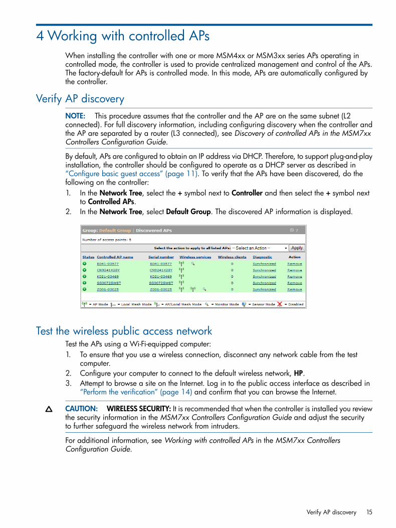
By default, APs are configured to obtain an IP address via DHCP. Therefore, to support plug-and-playinstallation, the controller should be configured to operate as a DHCP server as described in“Configure basic guest access” (page 11). To verify that the APs have been discovered, do thefollowing on the controller:1. In the Network Tree, select the + symbol next to Controller and then select the + symbol next
to Controlled APs.2. In the Network Tree, select Default Group. The discovered AP information is displayed.
Test the wireless public access networkTest the APs using a Wi-Fi-equipped computer:1. To ensure that you use a wireless connection, disconnect any network cable from the test
computer.2. Configure your computer to connect to the default wireless network, HP.3. Attempt to browse a site on the Internet. Log in to the public access interface as described in
“Perform the verification” (page 14) and confirm that you can browse the Internet.
CAUTION: WIRELESS SECURITY: It is recommended that when the controller is installed you reviewthe security information in the MSM7xx Controllers Configuration Guide and adjust the securityto further safeguard the wireless network from intruders.
For additional information, see Working with controlled APs in the MSM7xx ControllersConfiguration Guide.
Verify AP discovery 15

5 Support and other resourcesOnline Documentation
You can download documentation from the HP Support Website at: www.hp.com/support/manuals.Search by product number or name.
Contacting HPFor worldwide technical support information, see the HP support Website: www.hp.com/networking/supportBefore contacting HP, collect the following information:
• Product model names and numbers
• Technical support registration number (if applicable)
• Product serial numbers
• Error messages
• Operating system type and revision level
• Detailed questions
HP WebsitesFor additional information, see the following HP Websites:• www.hp.com/networking
• www.hp.com
Typographic conventionsTable 2 Document conventions
ElementConvention
Cross-reference links and e-mail addressesBlue text: Table 2 (page 16)
Website addressesBlue, underlined text: www.hp.com
Bold text • Keys that are pressed
• Text typed into a GUI element, such as a box
• GUI elements that are clicked or selected, such as menuand list items, buttons, tabs, and check boxes
WARNING! Indicates that failure to follow directions could result in bodily harm or death.
CAUTION: Indicates that failure to follow directions could result in damage to equipment or data.
IMPORTANT: Provides clarifying information or specific instructions.
NOTE: Provides additional information.
TIP: Provides helpful hints and shortcuts.
16 Support and other resources

A Safety and EMC regulatory statementsSafety information
Documentation reference symbol. If the product is marked withthis symbol, see the product documentation to get moreinformation about the product.
A WARNING in the manual denotes a hazard that can causeinjury or death.
WARNING
A Caution in the manual denotes a hazard that can damageequipment.
Caution
Do not proceed beyond aWARNING or Caution notice until youhave understood the hazardous conditions and have takenappropriate steps.
For LAN cable grounding• If your LAN covers an area served by more than one power distribution system, be sure their
safety grounds are securely interconnected.• LAN cables may occasionally be subject to hazardous transient voltages (such as lightning
or disturbances in the electrical utilities power grid). Handle exposed metal components ofthe network with caution.
ServicingThere are no user-serviceable parts inside these products. Any servicing, adjustment, maintenance,or repair must be performed only by service-trained personnel.These products do not have a power switch; they are powered on when the power cord is pluggedin.
Informations concernant la sécurité
Symbole de référence à la documentation. Si le produit estmarqué de ce symbole, reportez-vous à la documentation duproduit afin d'obtenir des informations plus détaillées.
Dans la documentation, un WARNING indique un dangersusceptible d'entraner des dommages corporels ou la mort.
WARNING
Un texte de mise en garde intitulé Caution indique un dangersusceptible de causer des dommages à l'équipement.
Caution
Ne continuez pas au-delà d'une rubriqueWARNING ou Cautionavant d'avoir bien compris les conditions présentant un dangeret pris les mesures appropriées.
Mise à la terre du câble de réseau local:• si votre réseau local s'étend sur une zone desservie par plus d'un système de distribution de
puissance, assurez-vous que les prises de terre de sécurité soient convenablementinterconnectées.
• Les câbles de réseaux locaux peuvent occasionnellement être soumis à des surtensionstransitoires dangereuses (telles que la foudre ou des perturbations dans le réseau d'alimentationpublic). Manipulez les composants métalliques du réseau avec précautions.
Safety information 17

Aucune pièce contenue à l'intérieur de ce produit ne peut être réparée par l'utilisateur. Toutdépannage, réglage, entretien ou réparation devra être confié exclusivement à un personnelqualifié.Cet appareil ne comporte pas de commutateur principal ; la mise sous tension est effectuée parbranchement du cordon d'alimentation.
Hinweise zur Sicherheit
Symbol für Dokumentationsverweis. Wenn das Produkt mitdiesem Symbol markiert ist, schlagen Sie bitte in derProduktdokumentation nach, um mehr Informationen über dasProdukt zu erhalten.
Eine WARNING in der Dokumentation symbolisiert eine Gefahr,die Verletzungen oder sogar Todesflle verursachen kann.
WARNING
Caution in der Dokumentation symbolisiert eine Gefahr, die disGerät beschädigen kann.
Caution
Fahren Sie nach dem Hinweis WARNING oder Caution erst fort,nachdem Sie den Gefahrenzustand verstanden und dieentsprechenden Maßnahmen ergriffen haben.
Für LAN-Kabelerdung:• Wenn Ihr LAN ein Gebiet umfaßt, das von mehr als einem Stromverteilungssystem beliefert
wird, müssen Sie sich vergewissern, daß die Sicherheitserdungen fest untereinander verbundensind.
• LAN-Kabel können gelegentlich gefährlichen Übergangsspannungen ausgesetzt werden(beispielsweise durch Blitz oder Störungen in dem Starkstromnetz des Elektrizitätswerks). Beider Handhabung exponierter Metallbestandteile des Netzwerkes Vorsicht walten lassen.
Dieses Gerät enthält innen keine durch den Benutzer zu wartenden Teile. Wartungs-, Anpassungs-,Instandhaltungs- oder Reparaturarbeiten dürfen nur von geschultem Bedienungspersonal durchgeführtwerden.Dieses Gerät hat keinen Netzschalter; es wird beim Anschließen des Netzkabels eingeschaltet.
Considerazioni sulla sicurezza
Simbolo di riferimento alla documentazione. Se il prodotto ècontrassegnato da questo simbolo, fare riferimento alladocumentazione sul prodotto per ulteriori informazioni su diesso.
La dicituraWARNING denota un pericolo che può causare lesionio morte.
WARNING
La dicituraCaution denota un pericolo che può danneggiare leattrezzature.
Caution
Non procedere oltre un avviso di WARNING o di Cautionprimadi aver compreso le condizioni di rischio e aver provveduto allemisure del caso.
Per la messa a terra dei cavi LAN:• se la vostra LAN copre un'area servita da più di un sistema di distribuzione elettrica, accertatevi
che i collegamenti a terra di sicurezza siano ben collegati fra loro;• i cavi LAN possono occasionalmente andare soggetti a pericolose tensioni transitorie (ad
esempio, provocate da lampi o disturbi nella griglia d'alimentazione della società elettrica);siate cauti nel toccare parti esposte in metallo della rete.
18 Safety and EMC regulatory statements

Nessun componente di questo prodotto può essere riparato dall'utente. Qualsiasi lavoro diriparazione, messa a punto, manutenzione o assistenza va effettuato esclusivamente da personalespecializzato.Questo apparato non possiede un commutatore principale; si mette scotto tensione all'inserirsi ilcavo d'alimentazione.
Consideraciones sobre seguridad
Símbolo de referencia a la documentación. Si el producto vamarcado con este símbolo, consultar la documentación delproducto a fin de obtener mayor información sobre el producto.
Una WARNING en la documentación señala un riesgo quepodría resultar en lesiones o la muerte.
WARNING
Una Caution en la documentación señala un riesgo que podríaresultar en averías al equipo.
Caution
No proseguir después de un símbolo de WARNING o Cautionhasta no haber entendido las condiciones peligrosas y habertomado las medidas apropiadas.
Puesta a tierra del cable de la red local (LAN):• Si la LAN abarca un área cuyo suministro eléctrico proviene de más de una red de distribución
de electricidad, cerciorarse de que las puestas a tierra estén conectadas entre sí de modoseguro.
• Es posible que los cables de la LAN se vean sometidos de vez en cuando a voltajesmomentáneos que entrañen peligro (rayos o alteraciones en la red de energía eléctrica).Manejar con precaución los componentes de metal de la LAN que estén al descubierto.
Este aparato no contiene pieza alguna susceptible de reparación por parte del usuario. Todas lasreparaciones, ajustes o servicio de mantenimiento debe realizarlos solamente el técnico.Este producto no tiene interruptor de potencia; se activa cuando se enchufa el cable dealimentación.
Consideraciones sobre seguridad 19

Safety information (Japan)
Japan power cord warning
20 Safety and EMC regulatory statements

Safety information (China)
EMC Regulatory Statements
FCC Class BThis equipment has been tested and found to comply with the limits for a Class B digital device,pursuant to Part 15 of the FCC Rules. Theses limits are designed to provide reasonable protectionagainst harmful interference in a residential installation. This equipment generates, uses, and canradiate radio frequency energy and, if not installed and used in accordance with the instructions,may cause harmful interference to radio communications. However, there is no guarantee thatinterference will not occur in a particular installation. If this equipment does cause harmfulinterference to radio or television reception, which can be determined by turning the equipmentoff and on, the user is encouraged to try to correct the interference by one or more of the followingmeasures:• Reorient or relocate the receiving antenna• Increase the separation between the equipment and the receiver
Safety information (China) 21

• Connect the equipment into an outlet that is on a circuit different from that to which the receiveris connected.
• Consult the dealer or an experienced radio/TV technician for help."
CAUTION: Any changes or modifications to this equipment not expressly approved by theHewlett-Packard Company may cause harmful interference and void the FCC authorization tooperate this equipment.
Japan
VCCI Class B
Korea
Class B
Turkish recycling notice
Türkiye Cumhuriyeti: EEE Yönetmeliğine Uygundur
Vietnamese Information Technology and Communications compliance marking
22 Safety and EMC regulatory statements

European Community Declaration of Conformity
EMC Regulatory Statements 23

B Recycle statementsWaste Electrical and Electronic Equipment (WEEE) statements
English recycling noticeDisposal of waste equipment by users in private household in the European Union
This symbol means do not dispose of your product with your other household waste. Instead, you shouldprotect human health and the environment by handing over your waste equipment to a designatedcollection point for the recycling of waste electrical and electronic equipment. For more information,please contact your household waste disposal service
Bulgarian recycling noticeИзхвърляне на отпадъчно оборудване от потребители в частни домакинства в Европейскиясъюз
Този символ върху продукта или опаковката му показва, че продуктът не трябва да се изхвърля заеднос другите битови отпадъци. Вместо това, трябва да предпазите човешкото здраве и околната среда,като предадете отпадъчното оборудване в предназначен за събирането му пункт за рециклиране нанеизползваемо електрическо и електронно борудване. За допълнителна информация се свържете сфирмата по чистота, чиито услуги използвате.
Czech recycling noticeLikvidace zařízení v domácnostech v Evropské unii
Tento symbol znamená, že nesmíte tento produkt likvidovat spolu s jiným domovním odpadem. Místotoho byste měli chránit lidské zdraví a životní prostředí tím, že jej předáte na k tomu určené sběrnépracoviště, kde se zabývají recyklací elektrického a elektronického vybavení. Pro více informací kontaktujtespolečnost zabývající se sběrem a svozem domovního odpadu.
Danish recycling noticeBortskaffelse af brugt udstyr hos brugere i private hjem i EU
Dette symbol betyder, at produktet ikke må bortskaffes sammen med andet husholdningsaffald. Du skali stedet den menneskelige sundhed og miljøet ved at afl evere dit brugte udstyr på et dertil beregnetindsamlingssted for af brugt, elektrisk og elektronisk udstyr. Kontakt nærmeste renovationsafdeling foryderligere oplysninger.
Dutch recycling noticeInzameling van afgedankte apparatuur van particuliere huishoudens in de Europese Unie
Dit symbool betekent dat het product niet mag worden gedeponeerd bij het overige huishoudelijke afval.Bescherm de gezondheid en het milieu door afgedankte apparatuur in te leveren bij een hiervoor bestemdinzamelpunt voor recycling van afgedankte elektrische en elektronische apparatuur. Neem voor meerinformatie contact op met uw gemeentereinigingsdienst.
24 Recycle statements

Estonian recycling noticeÄravisatavate seadmete likvideerimine Euroopa Liidu eramajapidamistes
See märk näitab, et seadet ei tohi visata olmeprügi hulka. Inimeste tervise ja keskkonna säästmise nimeltuleb äravisatav toode tuua elektriliste ja elektrooniliste seadmete käitlemisega egelevasse kogumispunkti.Küsimuste korral pöörduge kohaliku prügikäitlusettevõtte poole.
Finnish recycling noticeKotitalousjätteiden hävittäminen Euroopan unionin alueella
Tämä symboli merkitsee, että laitetta ei saa hävittää muiden kotitalousjätteiden mukana. Sen sijaan sinunon suojattava ihmisten terveyttä ja ympäristöä toimittamalla käytöstä poistettu laite sähkö- taielektroniikkajätteen kierrätyspisteeseen. Lisätietoja saat jätehuoltoyhtiöltä.
French recycling noticeMise au rebut d'équipement par les utilisateurs privés dans l'Union Européenne
Ce symbole indique que vous ne devez pas jeter votre produit avec les ordures ménagères. Il est devotre responsabilité de protéger la santé et l'environnement et de vous débarrasser de votre équipementen le remettant à une déchetterie effectuant le recyclage des équipements électriques et électroniques.Pour de plus amples informations, prenez contact avec votre service d'élimination des ordures ménagères.
German recycling noticeEntsorgung von Altgeräten von Benutzern in privaten Haushalten in der EU
Dieses Symbol besagt, dass dieses Produkt nicht mit dem Haushaltsmüll entsorgt werden darf. ZumSchutze der Gesundheit und der Umwelt sollten Sie stattdessen Ihre Altgeräte zur Entsorgung einer dafürvorgesehenen Recyclingstelle für elektrische und elektronische Geräte übergeben. Weitere Informationenerhalten Sie von Ihrem Entsorgungsunternehmen für Hausmüll.
Greek recycling noticeΑπόρριψη άχρηοτου εξοπλισμού από ιδιώτες χρήστες στην Ευρωπαϊκή Ένωση
Αυτό το σύμβολο σημαίνει ότι δεν πρέπει να απορρίψετε το προϊόν με τα λοιπά οικιακά απορρίμματα.Αντίθετα, πρέπει να προστατέψετε την ανθρώπινη υγεία και το περιβάλλον παραδίδοντας τον άχρηστοεξοπλισμό σας σε εξουσιοδοτημένο σημείο συλλογής για την ανακύκλωση άχρηστου ηλεκτρικού καιηλεκτρονικού εξοπλισμού. Για περισσότερες πληροφορίες, επικοινωνήστε με την υπηρεσία απόρριψηςαπορριμμάτων της περιοχής σας.
Hungarian recycling noticeA hulladék anyagok megsemmisítése az Európai Unió háztartásaiban
Ez a szimbólum azt jelzi, hogy a készüléket nem szabad a háztartási hulladékkal együtt kidobni. Ehelyetta leselejtezett berendezéseknek az elektromos vagy elektronikus hulladék átvételére kijelölt helyen történőbeszolgáltatásával megóvja az emberi egészséget és a környezetet.További információt a helyiköztisztasági vállalattól kaphat.
Waste Electrical and Electronic Equipment (WEEE) statements 25

Italian recycling noticeSmaltimento di apparecchiature usate da parte di utenti privati nell'Unione Europea
Questo simbolo avvisa di non smaltire il prodotto con i normali rifi uti domestici. Rispettare la saluteumana e l'ambiente conferendo l'apparecchiatura dismessa a un centro di raccolta designato per ilriciclo di apparecchiature elettroniche ed elettriche. Per ulteriori informazioni, rivolgersi al servizio perlo smaltimento dei rifi uti domestici.
Latvian recycling noticeEuropos Sąjungos namų ūkio vartotojų įrangos atliekų šalinimas
Šis simbolis nurodo, kad gaminio negalima išmesti kartu su kitomis buitinėmis atliekomis. Kadapsaugotumėte žmonių sveikatą ir aplinką, pasenusią nenaudojamą įrangą turite nuvežti į elektrinių irelektroninių atliekų surinkimo punktą. Daugiau informacijos teiraukitės buitinių atliekų surinkimo tarnybos.
Lithuanian recycling noticeNolietotu iekārtu iznīcināšanas noteikumi lietotājiem Eiropas Savienības privātajās mājsaimniecībās
Šis simbols norāda, ka ierīci nedrīkst utilizēt kopā ar citiem mājsaimniecības atkritumiem. Jums jārūpējaspar cilvēku veselības un vides aizsardzību, nododot lietoto aprīkojumu otrreizējai pārstrādei īpašā lietotuelektrisko un elektronisko ierīču savākšanas punktā. Lai iegūtu plašāku informāciju, lūdzu, sazinieties arsavu mājsaimniecības atkritumu likvidēšanas dienestu.
Polish recycling noticeUtylizacja zużytego sprzętu przez użytkowników w prywatnych gospodarstwach domowych wkrajach Unii Europejskiej
Ten symbol oznacza, że nie wolno wyrzucać produktu wraz z innymi domowymi odpadkami.Obowiązkiem użytkownika jest ochrona zdrowa ludzkiego i środowiska przez przekazanie zużytegosprzętu do wyznaczonego punktu zajmującego się recyklingiem odpadów powstałych ze sprzętuelektrycznego i elektronicznego. Więcej informacji można uzyskać od lokalnej firmy zajmującej wywozemnieczystości.
Portuguese recycling noticeDescarte de equipamentos usados por utilizadores domésticos na União Europeia
Este símbolo indica que não deve descartar o seu produto juntamente com os outros lixos domiciliares.Ao invés disso, deve proteger a saúde humana e o meio ambiente levando o seu equipamento paradescarte em um ponto de recolha destinado à reciclagem de resíduos de equipamentos eléctricos eelectrónicos. Para obter mais informações, contacte o seu serviço de tratamento de resíduos domésticos.
26 Recycle statements

Romanian recycling noticeCasarea echipamentului uzat de către utilizatorii casnici din Uniunea Europeană
Acest simbol înseamnă să nu se arunce produsul cu alte deşeuri menajere. În schimb, trebuie să protejaţisănătatea umană şi mediul predând echipamentul uzat la un punct de colectare desemnat pentru reciclareaechipamentelor electrice şi electronice uzate. Pentru informaţii suplimentare, vă rugăm să contactaţiserviciul de eliminare a deşeurilor menajere local.
Slovak recycling noticeLikvidácia vyradených zariadení používateľmi v domácnostiach v Európskej únii
Tento symbol znamená, že tento produkt sa nemá likvidovať s ostatným domovým odpadom. Namiestotoho by ste mali chrániť ľudské zdravie a životné prostredie odovzdaním odpadového zariadenia nazbernom mieste, ktoré je určené na recykláciu odpadových elektrických a elektronických zariadení.Ďalšie informácie získate od spoločnosti zaoberajúcej sa likvidáciou domového odpadu.
Spanish recycling noticeEliminación de los equipos que ya no se utilizan en entornos domésticos de la Unión Europea
Este símbolo indica que este producto no debe eliminarse con los residuos domésticos. En lugar de ello,debe evitar causar daños a la salud de las personas y al medio ambiente llevando los equipos que noutilice a un punto de recogida designado para el reciclaje de equipos eléctricos y electrónicos que yano se utilizan. Para obtener más información, póngase en contacto con el servicio de recogida deresiduos domésticos.
Swedish recycling noticeHantering av elektroniskt avfall för hemanvändare inom EU
Den här symbolen innebär att du inte ska kasta din produkt i hushållsavfallet. Värna i stället om naturoch miljö genom att lämna in uttjänt utrustning på anvisad insamlingsplats. Allt elektriskt och elektronisktavfall går sedan vidare till återvinning. Kontakta ditt återvinningsföretag för mer information.
Waste Electrical and Electronic Equipment (WEEE) statements 27