hp elitebook revolve 810 g3 - raru · product name hp elitebook revolve 810 g3 processors intel®...
TRANSCRIPT

HP EliteBook Revolve 810 G3
Maintenance and Service Guide

© Copyright 2015 HP Development Company, L.P.
Product notice
Bluetooth is a trademark owned by its proprietor and used by HP Inc. under license. DTS, the Symbol, & DTS and the Symbol together are registered trademarks, and DTS Sound is a trademark of DTS, Inc. © DTS, Inc. All Rights Reserved. Intel and Core are U.S. registered trademarks of Intel Corporation. Microsoft and Windows are U.S. registered trademarks of Microsoft Corporation. SD Logo is a trademark of its proprietor.
This guide describes features that are common to most models. Some features may not be available on your computer.
Not all features are available in all editions of Windows 10 or Windows 8. This computer may require upgraded and/or separately purchased hardware, drivers and/or software to take full advantage of Windows 10 or Windows 8 functionality. See http://www.microsoft.com for details.
The information contained herein is subject to change without notice. The only warranties for HP products and services are set forth in the express warranty statements accompanying such products and services. Nothing herein should be construed as constituting an additional warranty. HP shall not be liable for technical or editorial errors or omissions contained herein.
Second Edition: August 2015
First Edition: January 2015
Document Part Number: 780915-002

Important Notice about Customer Self-Repair Parts
CAUTION: Your computer includes Customer Self-Repair parts and parts that should only be accessed by an authorized service provider. See Chapter 5, "Removal and replacement procedures for Customer Self-Repair parts," for details. Accessing parts described in Chapter 6, "Removal and replacement procedures for Authorized Service Provider only parts," can damage the computer or void your warranty.
iii

iv Important Notice about Customer Self-Repair Parts

Safety warning notice
WARNING! To reduce the possibility of heat-related injuries or of overheating the device, do not place the device directly on your lap or obstruct the device air vents. Use the device only on a hard, flat surface. Do not allow another hard surface, such as an adjoining optional printer, or a soft surface, such as pillows or rugs or clothing, to block airflow. Also, do not allow the AC adapter to contact the skin or a soft surface, such as pillows or rugs or clothing, during operation. The device and the AC adapter comply with the user-accessible surface temperature limits defined by the International Standard for Safety of Information Technology Equipment (IEC 60950).
v

vi Safety warning notice

Table of contents
1 Product description ....................................................................................................................................... 1
2 External component identification ................................................................................................................. 6
Display ................................................................................................................................................................... 8
Keys ...................................................................................................................................................................... 10
Lights ................................................................................................................................................................... 11
TouchPad ............................................................................................................................................................. 12
Left side ............................................................................................................................................................... 12
Right side ............................................................................................................................................................. 13
Rear ...................................................................................................................................................................... 15
Bottom ................................................................................................................................................................. 16
3 Illustrated parts catalog .............................................................................................................................. 17
Service tag ........................................................................................................................................................... 17
Computer major components ............................................................................................................................. 18
Miscellaneous parts ............................................................................................................................................. 22
4 Removal and replacement procedures preliminary requirements .................................................................... 24
Tools required ...................................................................................................................................................... 24
Service considerations ........................................................................................................................................ 24
Plastic parts ....................................................................................................................................... 24
Cables and connectors ...................................................................................................................... 25
Drive handling ................................................................................................................................... 25
Grounding guidelines ........................................................................................................................................... 26
Electrostatic discharge damage ....................................................................................................... 26
Packaging and transporting guidelines ......................................................................... 27
Workstation guidelines ................................................................................................... 27
Equipment guidelines ..................................................................................................... 28
5 Removal and replacement procedures for Customer Self-Repair parts ............................................................. 29
Component replacement procedures ................................................................................................................. 29
Battery ............................................................................................................................................... 29
Service cover ..................................................................................................................................... 30
WWAN module ................................................................................................................................... 32
WLAN module .................................................................................................................................... 34
Solid-state drive ................................................................................................................................ 36
vii

Memory module ................................................................................................................................ 38
6 Removal and replacement procedures for Authorized Service Provider parts ................................................... 39
Component replacement procedures ................................................................................................................. 39
Unlocking the device and disabling Always On Remote Management (select HP devices only) ..... 39
NFC board .......................................................................................................................................... 40
Keyboard ........................................................................................................................................... 41
Bottom cover ..................................................................................................................................... 44
Speakers ............................................................................................................................................ 47
Power button board .......................................................................................................................... 48
RTC battery ........................................................................................................................................ 49
System board .................................................................................................................................... 50
Fan/heat sink assembly .................................................................................................................... 53
Hinge cover ........................................................................................................................................ 55
Display assembly .............................................................................................................................. 56
7 Computer Setup (BIOS), TPM, and HP Sure Start – Windows 10 ........................................................................ 58
Using Computer Setup ......................................................................................................................................... 58
Starting Computer Setup .................................................................................................................. 58
Navigating and selecting in Computer Setup ................................................................................... 59
Restoring factory settings in Computer Setup ................................................................................. 59
Updating the BIOS ............................................................................................................................. 60
Determining the BIOS ..................................................................................................... 60
Downloading a BIOS update ........................................................................................... 60
Changing the boot order using the f9 prompt .................................................................................. 61
TPM BIOS settings (select products only) ........................................................................................................... 62
Using HP Sure Start (select products only) ......................................................................................................... 62
8 HP PC Hardware Diagnostics (UEFI) – Windows 10 ........................................................................................... 63
Downloading HP PC Hardware Diagnostics (UEFI) to a USB device .................................................................... 64
9 Computer Setup (BIOS), MultiBoot, and HP PC Hardware Diagnostics (UEFI) – Windows 8 ................................... 65
Using Computer Setup ......................................................................................................................................... 65
Starting Computer Setup .................................................................................................................. 65
Navigating and selecting in Computer Setup ................................................................................... 65
Restoring factory settings in Computer Setup ................................................................................. 66
Updating the BIOS ............................................................................................................................. 67
Determining the BIOS version ........................................................................................ 67
Downloading a BIOS update ........................................................................................... 67
Using MultiBoot ................................................................................................................................................... 68
viii

About the boot device order ............................................................................................................. 68
Choosing MultiBoot preferences ...................................................................................................... 68
Setting a new boot order in Computer Setup ................................................................. 68
Dynamically choosing a boot device using the f9 prompt ............................................. 69
Setting a MultiBoot Express prompt .............................................................................. 69
Entering MultiBoot Express preferences ....................................................................... 70
Using HP PC Hardware Diagnostics (UEFI) .......................................................................................................... 70
Downloading HP PC Hardware Diagnostics (UEFI) to a USB device .................................................. 70
Using HP Sure Start (select models only) ........................................................................................................... 71
10 Computer Setup (BIOS), MultiBoot, and HP PC Hardware Diagnostics (UEFI) – Windows 7 ................................. 72
Using Computer Setup ......................................................................................................................................... 72
Starting Computer Setup .................................................................................................................. 72
Navigating and selecting in Computer Setup ................................................................................... 72
Restoring factory settings in Computer Setup ................................................................................. 73
Updating the BIOS ............................................................................................................................. 74
Determining the BIOS version ........................................................................................ 74
Downloading a BIOS update ........................................................................................... 74
Using MultiBoot ................................................................................................................................................... 75
About the boot device order ............................................................................................................. 75
Choosing MultiBoot preferences ...................................................................................................... 75
Setting a new boot order in Computer Setup ................................................................. 75
Dynamically choosing a boot device using the f9 prompt ............................................. 76
Setting a MultiBoot Express prompt .............................................................................. 76
Entering MultiBoot Express preferences ....................................................................... 76
Using HP PC Hardware Diagnostics (UEFI) (select models only) ........................................................................ 77
Downloading HP PC Hardware Diagnostics (UEFI) to a USB device .................................................. 77
11 Specifications ........................................................................................................................................... 79
Computer specifications ...................................................................................................................................... 79
12 Backup and recovery – Windows 10 ............................................................................................................. 80
Creating recovery media and backups ................................................................................................................ 80
Creating HP Recovery media (select products only) ........................................................................ 81
Using Windows Tools ........................................................................................................................................... 82
Restore and recovery .......................................................................................................................................... 82
Recovering using HP Recovery Manager .......................................................................................... 83
What you need to know before you get started ............................................................ 83
Using the HP Recovery partition (select products only) ................................................ 84
Using HP Recovery media to recover ............................................................................. 84
ix

Changing the computer boot order ................................................................................ 85
Removing the HP Recovery partition (select products only) ......................................... 85
13 Backup and recovery – Windows 8 ............................................................................................................... 86
Backing up your information ............................................................................................................................... 86
Performing a system recovery ............................................................................................................................ 86
Using the Windows recovery tools ................................................................................................... 87
Using f11 recovery tools ................................................................................................................... 87
Using Windows operating system media (purchased separately) ................................................... 88
Using Windows Refresh or Windows Reset ...................................................................................... 89
Using HP Software Setup .................................................................................................................. 89
14 Backup and recovery – Windows 7 ............................................................................................................... 90
Creating recovery media and backups ................................................................................................................ 90
Guidelines .......................................................................................................................................... 90
Creating recovery media with HP Recovery Disc Creator ................................................................. 90
Creating recovery media ................................................................................................. 91
Backing up your information ............................................................................................................ 91
Performing a system recovery ............................................................................................................................ 92
Using the Windows recovery tools ................................................................................................... 92
Using f11 recovery tools (select models only) ................................................................................. 93
Using Windows 7 operating system media ...................................................................................... 93
15 Statement of Volatility .............................................................................................................................. 95
Non-volatile memory usage ................................................................................................................................ 97
Questions and answers ....................................................................................................................................... 99
16 Power cord set requirements .................................................................................................................... 101
Requirements for all countries ......................................................................................................................... 101
Requirements for specific countries and regions ............................................................................................. 101
17 Recycling ................................................................................................................................................ 103
Index ........................................................................................................................................................... 104
x

1 Product description
Category Description
Product Name HP EliteBook Revolve 810 G3
Processors ● Intel® Core® i7-5600U 2.60-GHz (SC turbo up to 3.20-GHz) processor (4.0-MB L3 cache, dual core, 15-W)
● Intel Core i7-5500U 2.40-GHz (SC turbo up to 3.00-GHz) processor (4.0-MB L3 cache, dual core, 15-W)
● Intel Core i5-5300U 2.30-GHz (SC turbo up to 2.90-GHz) processor (3.0-MB L3 cache, dual core, 15-W)
● Intel Core i5-5200U 2.20-GHz (SC turbo up to 2.70-GHz) processor (3.0-MB L3 cache, dual core, 15-W)
● Intel Core i3-5010U 2.10-GHz processor (3.0-MB L3 cache, dual core, 15-W)
Chipset Intel integrated on processor
Graphics Intel UMA Graphics with shared video memory
Support for dual-display ports through the dock
Panel 11.6-in, high-definition (HD), (1366×768), light-emitting diode (LED), low-voltage differential signalling (LVDS), UWVA , ultraslim display with webcam and microphone
Touchscreen enabled. Touch Controller: Atmel, 2952T1
Typical brightness: 400 nits
Memory One customer-accessible/upgradable memory module slot + 4-GB on the system board
Support for DDR3L PC-3 12800 (1600)
Support for 12288-MB of system RAM in the following configurations:
● 12288-MB (8192-MB memory module + 4096-MB on system board)
● 8192-MB (4096-MB memory module + 4096-MB on system board)
● 4096-MB (4096-MB on system board)
Solid-state drive Serial ATA III
Support for the following single solid-state drive configurations:
● 512-MB, M2, SATA-3
● 256-MB, M2, SATA-3
● 256-MB, M2, SATA-3, SED, Opal 2
● 256-MB, M2, SATA-3, TLC
● 180-MB, M2, SATA-3
● 180-MB, M2, SATA-3, SED, Opal 2
● 128-MB, M2, SATA-3
● 128-MB, M2, SATA-3, TLC
Audio and video DTS Studio sound
1
Category Description
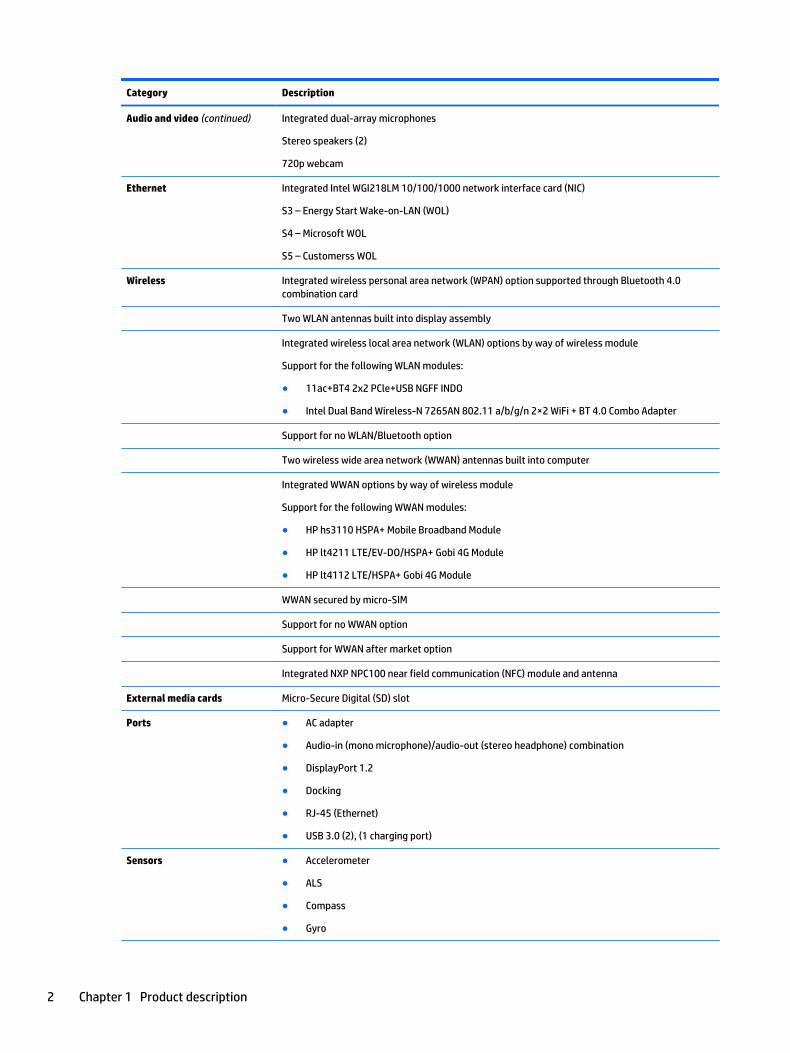
Audio and video (continued) Integrated dual-array microphones
Stereo speakers (2)
720p webcam
Ethernet Integrated Intel WGI218LM 10/100/1000 network interface card (NIC)
S3 – Energy Start Wake-on-LAN (WOL)
S4 – Microsoft WOL
S5 – Customerss WOL
Wireless Integrated wireless personal area network (WPAN) option supported through Bluetooth 4.0 combination card
Two WLAN antennas built into display assembly
Integrated wireless local area network (WLAN) options by way of wireless module
Support for the following WLAN modules:
● 11ac+BT4 2x2 PCle+USB NGFF INDO
● Intel Dual Band Wireless-N 7265AN 802.11 a/b/g/n 2×2 WiFi + BT 4.0 Combo Adapter
Support for no WLAN/Bluetooth option
Two wireless wide area network (WWAN) antennas built into computer
Integrated WWAN options by way of wireless module
Support for the following WWAN modules:
● HP hs3110 HSPA+ Mobile Broadband Module
● HP lt4211 LTE/EV-DO/HSPA+ Gobi 4G Module
● HP lt4112 LTE/HSPA+ Gobi 4G Module
WWAN secured by micro-SIM
Support for no WWAN option
Support for WWAN after market option
Integrated NXP NPC100 near field communication (NFC) module and antenna
External media cards Micro-Secure Digital (SD) slot
Ports ● AC adapter
● Audio-in (mono microphone)/audio-out (stereo headphone) combination
● DisplayPort 1.2
● Docking
● RJ-45 (Ethernet)
● USB 3.0 (2), (1 charging port)
Sensors ● Accelerometer
● ALS
● Compass
● Gyro
2 Chapter 1 Product description
Category Description
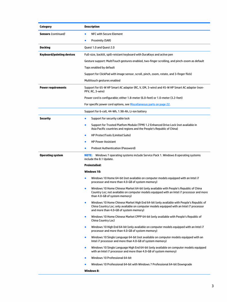
Sensors (continued) ● NFC with Secure Element
● Proximity (SAR)
Docking Quest 1.0 and Quest 2.0
Keyboard/pointing devices Full-size, backlit, spill-reistant keyboard with DuraKeys and active pen
Gesture support: MultiTouch gestures enabled, two-finger scrolling, and pinch-zoom as default
Taps enabled by default
Support for ClickPad with image sensor, scroll, pinch, zoom, rotate, and 3-finger flick)
Multitouch gestures enabled
Power requirements Support for 65-W HP Smart AC adapter (RC, V, EM, 3-wire) and 45-W HP Smart AC adapter (non-PFV, RC, 3-wire)
Power cord is configurable; either 1.8-meter (6.0-feet) or 1.0-meter (3.2-feet)
For specific power cord options, see Miscellaneous parts on page 22.
Support for 6-cell, 44-Wh, 1.98-Ah, Li-ion battery
Security ● Support for security cable lock
● Support for Trusted Platfom Module (TPM) 1.2 Enhanced Drive Lock (not available in Asia Pacific countries and regions and the People’s Republic of China)
● HP ProtectTools (Limited Suite)
● HP Power Assistant
● Preboot Authentication (Password)
Operating system NOTE: Windows 7 operating systems include Service Pack 1. Windows 8 operating systems include the 8.1 Update.
Preinstalled:
Windows 10:
● Windows 10 Home 64-bit (not available on computer models equipped with an Intel i7 processor and more than 4.0-GB of system memory)
● Windows 10 Home Chinese Market 64-bit (only available with People’s Republic of China Country Loc; not available on computer models equipped with an Intel i7 processor and more than 4.0-GB of system memory)
● Windows 10 Home Chinese Market High End 64-bit (only available with People’s Republic of China Country Loc; only available on computer models equipped with an Intel i7 processor and more than 4.0-GB of system memory)
● Windows 10 Home Chinese Market CPPP 64-bit (only available with People’s Republic of China Country Loc)
● Windows 10 High End 64-bit (only available on computer models equipped with an Intel i7 processor and more than 4.0-GB of system memory)
● Windows 10 Single Language 64-bit (not available on computer models equipped with an Intel i7 processor and more than 4.0-GB of system memory)
● Windows 10 Single Language High End 64-bit (only available on computer models equipped with an Intel i7 processor and more than 4.0-GB of system memory)
● Windows 10 Professional 64-bit
● Windows 10 Professional 64-bit with Windows 7 Professional 64-bit Downgrade
Windows 8:
3

Category Description
Operating system (continued) ● Windows 8.1 Chinese Market 64-bit (only available with People’s Republic of China Country Loc)
● Windows 8.1 Emerging Markets 64-bit (not available on computer models equipped with an Intel i7 processor and more than 4.0-GB of system memory)
● Windows 8.1 Emerging Markets High End 64-bit (only available on computer models equipped with an Intel i7 processor and more than 4.0-GB of system memory)
● Windows 8.1 Multilanguage 64-bit (not available on computer models equipped with an Intel i7 processor and more than 4.0-GB of system memory)
● Windows 8.1 Multilanguage Hight End 64-bit (only available on computer models equipped with an Intel i7 processor and more than 4.0-GB of system memory)
● Windows 8.1 Professional 64-bit
● Windows 8.1 Professional 64-bit – MSNA
● Windows 8.1 Professional for Education 64-bit
● Windows 8.1 Professional 64-bit DPK with Windows 7 Professional 64-bit image (not available in Asia Pacific countries and regions and the People’s Republic of China)
● Windows 8.1 Professional 64-bit DPK with Windows 7 Professional 64-bit image – MSNA
Windows 7: Windows 7 Professional 64-bit and Windows 7 Professional 64-bit – MSNA
FreeDos 2.0
Restore media – DRDVD:
● DRDVD Windows 10 (available with any Windows 10 operating system, required with any Windows 10 Downgrade operating system)
● DRDVD Windows 8.1 (available with Windows 8.1 or Windows 8.1 Professional Loc, required with any Windows 8.1 Professional Downgrade operating system)
● DRDVD Windows 7 (available with Windows 10 Professional, Windows 8.1 Professional, or Windows 7 Professional or Downgrade Loc)
Restore media – OSDVD:
● Windows 10 OSDVD Downgrade RTF (required with any Windows 10 Downgrade operating system)
● Windows 8.1 (Update) 64-bit (for service only)
● Windows 8.1 Country-Specific (Update) 64-bit (for service only)
● Windows 8.1 Emerging Market (Update) 64-bit (for service only)
● Windows 8.1 Professional (Update) 64-bit (only available and required with Windows 8.1 Professional Downgrade operating system; not available in Asia Pacific countries or regions or the People’s Republic of China)
● Windows 8.1 Professional for Education (Update) 64-bit (for service only)
● Windows 7 Professional 64-bit (available with Windows 10 Professional, Windows 8.1 Professional, or Windows 7 Professional Loc; not available in Asia Pacific countries or regions or the People’s Republic of China)
Certified: Microsoft WHQL
Web-only support:
● Windows 10 Enterprise
● Windows 8.1 Enterprise 64-bit
● Windows 8 Chinese Market 64-bit
4 Chapter 1 Product description

Category Description
Operating system (continued) ● Windows 8 Emerging Markets 64-bit
● Windows 8 Multilanguage 64-bit
● Windows 8 Professional 64-bit
● Windows 7 Enterprise 64-bit
● Windows 7 Enterprise 32-bit
● Windows 7 Professional 32-bit
Serviceability End user replaceable part:
● AC adapter
● Battery
● Docking station
● Solid-state drive
● System memory
● WLAN module
● WWAN module
5
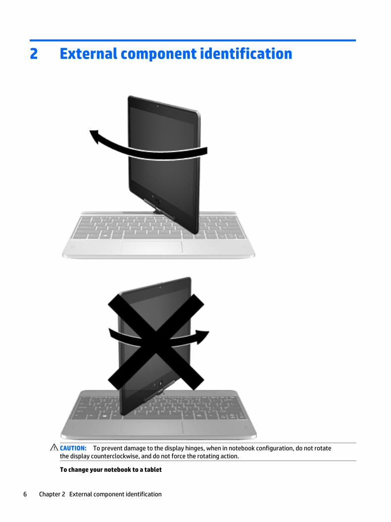
2 External component identification
CAUTION: To prevent damage to the display hinges, when in notebook configuration, do not rotate the display counterclockwise, and do not force the rotating action.
To change your notebook to a tablet
6 Chapter 2 External component identification

1. Rotate the display clockwise 180 degrees until the display faces backwards.
2. Lower the display over the keyboard.
To change the tablet back into a notebook, reverse these steps.
7

Display
Item Component Description
(1) WWAN antennas (2)* Send and receive wireless signals to communicate with WWANs.
(2) Ambient light sensor Brightens or dims the display in response to ambient light.
(3) WLAN antennas (2)* Send and receive wireless signals to communicate with WLANs.
(4) Internal microphones (2) Record sound.
(5) Webcam light On: The webcam is in use.
(6) Webcam Records video and captures photographs. Some models allow you to video conference and chat online using streaming video.
For information on using the webcam:
● Windows 10 – Type camera in the taskbar search box, and then select Camera.
● Windows 8 – Access HP Support Assistant. To access HP Support Assistant on the Start screen, select the HP Support Assistant app.
● Windows 7 – Select Start > All Programs > Communication and Chat > HP WebCam.
(7) Windows Home button Returns you to the Start screen.
*The antennas are not visible on the outside of the computer. For optimal transmission, keep the areas immediately around the antennas free from obstructions.
8 Chapter 2 External component identification

Item Component Description
For wireless regulatory notices, see the section of the Regulatory, Safety, and Environmental Notices that applies to your country or region.
To access this guide:
Windows 10:
Select the Start button, select All apps, select HP Help and Support, and then select HP Documentation.
Windows 8 or Windows 7:
▲ Select the HP Support Assistant app on the Start screen, select My computer, and then select User guides.
Display 9

KeysNOTE: Your computer may look slightly different from the illustration in this section.
Item Component Description
(1) esc key Displays system information when pressed in combination with the fn key.
(2) fn key Executes frequently used system functions when pressed in combination with a function key, the num lk key, the esc key, or the b key.
(3) Windows button Displays the Windows Start menu.
(4) Function keys Execute frequently used system functions when pressed in combination with the fn key.
(5) Embedded numeric keypad When the keypad is turned on, it can be used like an external numeric keypad.
Each key on the keypad performs the function indicated by the icon in the upper-right corner of the key.
(6) Windows application key Displays options for a selected object.
10 Chapter 2 External component identification

LightsNOTE: Your computer may look slightly different from the illustration in this section.
Item Component Description
(1) Caps lock light On: Caps lock is on, which switches the keys to all capital letters.
(2) Mute light ● Amber: Computer sound is off.
● Off: Computer sound is on.
(3) Microphone mute light ● Amber: microphone sound is off.
● Off: Microphone is on.
(4) Wireless light ● On: An integrated wireless device, such as a WLAN device and/or a Bluetooth device, is on.
NOTE: On some models, the wireless light is amber when all wireless devices are off.
(5) Num lock light On: Num lock is on.
(6) TouchPad light ● On: The TouchPad is off.
● Off: The TouchPad is on.
Lights 11

TouchPadNOTE: Your computer may look slightly different from the illustration in this section.
Item Component Description
(1) TouchPad on/off button Turns the TouchPad on or off.
(2) TouchPad zone Moves the pointer and selects or activates items on the screen.
(3) Left TouchPad button Functions like the left button on an external mouse.
(4) Right TouchPad button Functions like the right button on an external mouse.
Left sideNOTE: Your computer may look slightly different from the illustration in this section.
Item Component Description
(1) Vent Enables airflow to cool internal components.
NOTE: The computer fan starts up automatically to cool internal components and prevent overheating. It is normal for the internal fan to cycle on and off during routine operation.
(2) Speaker Produces sound.
12 Chapter 2 External component identification
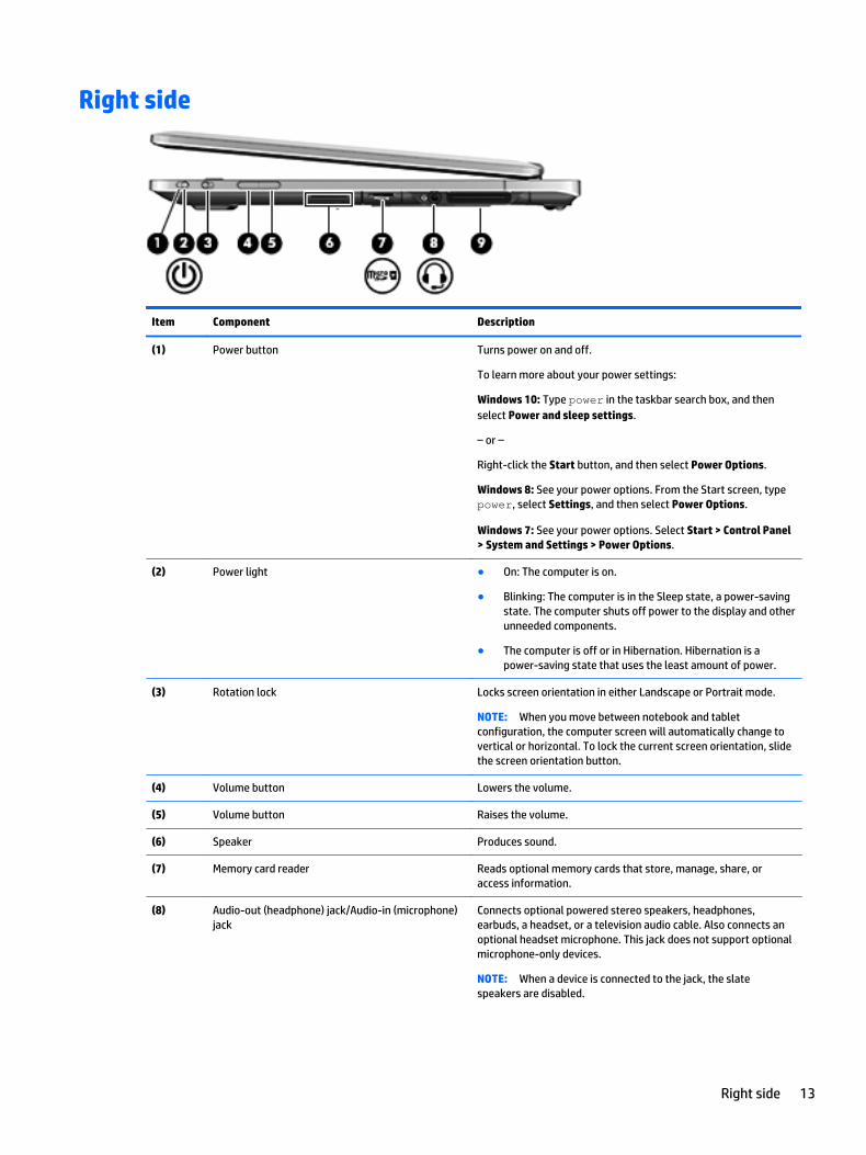
Right side
Item Component Description
(1) Power button Turns power on and off.
To learn more about your power settings:
Windows 10: Type power in the taskbar search box, and then select Power and sleep settings.
– or –
Right-click the Start button, and then select Power Options.
Windows 8: See your power options. From the Start screen, type power, select Settings, and then select Power Options.
Windows 7: See your power options. Select Start > Control Panel > System and Settings > Power Options.
(2) Power light ● On: The computer is on.
● Blinking: The computer is in the Sleep state, a power-saving state. The computer shuts off power to the display and other unneeded components.
● The computer is off or in Hibernation. Hibernation is a power-saving state that uses the least amount of power.
(3) Rotation lock Locks screen orientation in either Landscape or Portrait mode.
NOTE: When you move between notebook and tablet configuration, the computer screen will automatically change to vertical or horizontal. To lock the current screen orientation, slide the screen orientation button.
(4) Volume button Lowers the volume.
(5) Volume button Raises the volume.
(6) Speaker Produces sound.
(7) Memory card reader Reads optional memory cards that store, manage, share, or access information.
(8) Audio-out (headphone) jack/Audio-in (microphone) jack
Connects optional powered stereo speakers, headphones, earbuds, a headset, or a television audio cable. Also connects an optional headset microphone. This jack does not support optional microphone-only devices.
NOTE: When a device is connected to the jack, the slate speakers are disabled.
Right side 13
Item Component Description
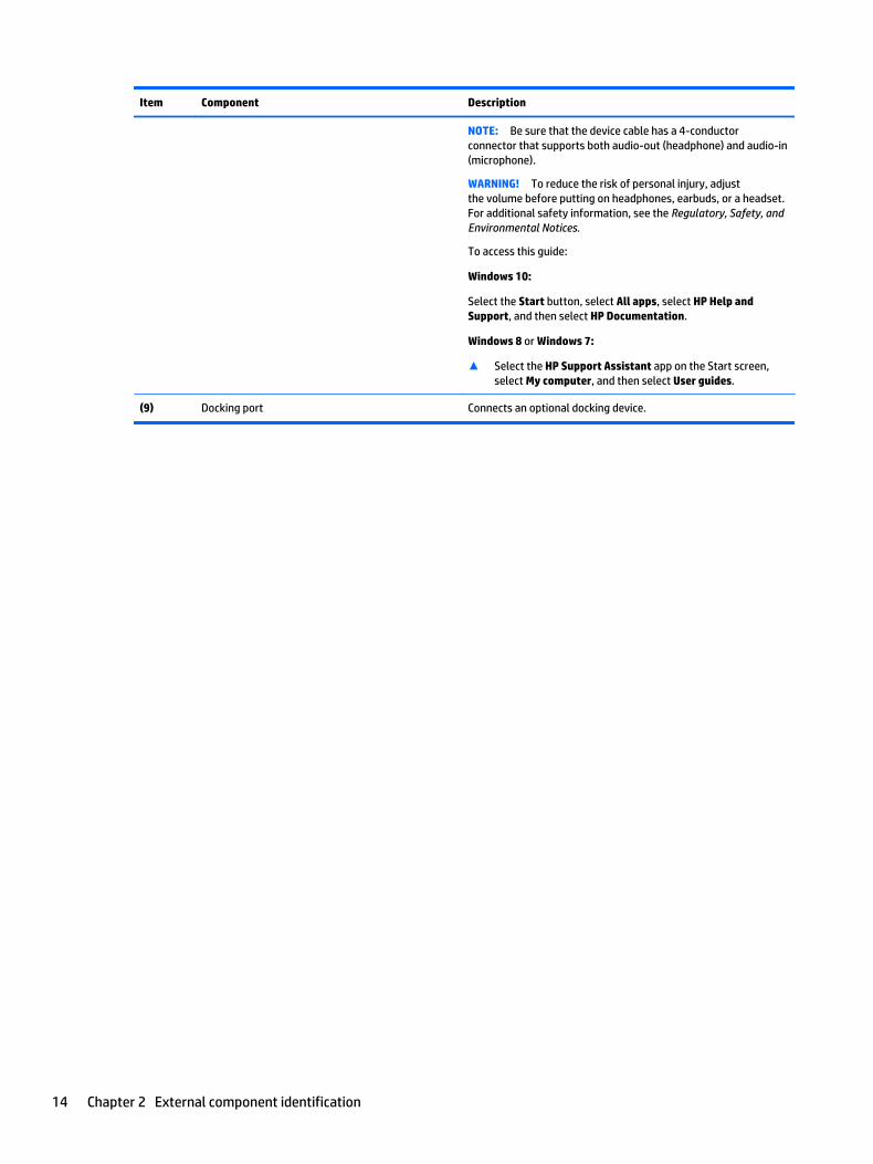
NOTE: Be sure that the device cable has a 4-conductor connector that supports both audio-out (headphone) and audio-in (microphone).
WARNING! To reduce the risk of personal injury, adjust the volume before putting on headphones, earbuds, or a headset. For additional safety information, see the Regulatory, Safety, and Environmental Notices.
To access this guide:
Windows 10:
Select the Start button, select All apps, select HP Help and Support, and then select HP Documentation.
Windows 8 or Windows 7:
▲ Select the HP Support Assistant app on the Start screen, select My computer, and then select User guides.
(9) Docking port Connects an optional docking device.
14 Chapter 2 External component identification

RearNOTE: Your computer may look slightly different from the illustration in this section.
Item Component Description
(1) RJ-45 (network) jack Connects a network cable.
● Green (left): The network is connected.
● Amber (right): Activity is occurring on the network.
(2) USB 3.0 port Connects an optional USB device, such as a keyboard, mouse, external drive, printer, scanner or USB hub.Connects an optional USB device, such as a keyboard, mouse, external drive, printer, scanner or USB hub.
(3) Security cable slot Attaches an optional security cable to the computer.
NOTE: The security cable is designed to act as a deterrent, but it may not prevent the computer from being mishandled or stolen.
(4) DisplayPort Connects an optional digital display device, such as a high-performance monitor or projector.
(5) USB 3.0 charging port Connects an optional USB device, such as a keyboard, mouse, external drive, printer, scanner or USB hub. Standard USB ports will not charge all USB devices or will charge using a low current. Some USB devices require power and require you to use a powered port.
NOTE: USB charging ports can also charge select models of cell phones and MP3 players, even when the computer is off.
(6) Power connector Connects an AC adapter.
(7) AC adapter light ● White: The AC adapter is connected and the battery is charged.
● Amber: The AC adapter is connected and the battery is charging.
● Off: The computer is using DC power.
Rear 15

BottomNOTE: Your computer may look slightly different from the illustration in this section.
Item Component Description
(1) Service cover Gives access to the hard drive, the wireless LAN module slot, the WWAN module slot (select models only), and the memory module slots.
CAUTION: To prevent an unresponsive system, replace the wireless module only with a wireless module authorized for use in the computer by the governmental agency that regulates wireless devices in your country or region.
(2) Vents Enables airflow to cool internal components.
NOTE: The computer fan starts up automatically to cool internal components and prevent overheating. It is normal for the internal fan to cycle on and off during routine operation.
(3) Near Field Communication (NFC) antenna Allows you to connect wirelessly with, communicate with, and transfer data/info to and from your Near Field Communication (NFC)-compatible devices.
(4) Battery bay Holds the battery.
(5) Battery bay cover release latch Releases the battery cover over the battery bay.
16 Chapter 2 External component identification

3 Illustrated parts catalog
Service tagWhen ordering parts or requesting information, provide the computer serial number and model number provided on the service tag. It is necessary to remove the battery to obtain these numbers. See Bottom on page 16 for battery removal instructions.
Item Description Function
(1) Product name This is the product name affixed to the front of the computer.
(2) Serial number (s/n) This is an alphanumeric identifier that is unique to each product.
(3) Part number/Product number (p/n) This number provides specific information about the product's hardware components. The part number helps a service technician to determine what components and parts are needed.
(4) Warranty period This number describes the duration of the warranty period for the computer.
(5) Model description This is the alphanumeric identifier used to locate documents, drivers, and support for the computer.
Service tag 17

Computer major components
18 Chapter 3 Illustrated parts catalog
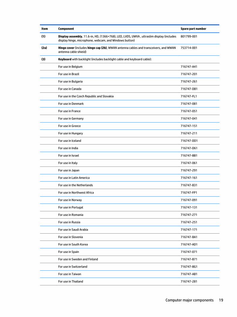
Item Component Spare part number
(1) Display assembly, 11.6-in, HD, (1366×768), LED, LVDS, UWVA , ultraslim display (includes display hinge, microphone, webcam, and Windows button)
801799-001
(2a) Hinge cover (includes hinge cap (2b), WWAN antenna cables and transceivers, and WWAN antenna cable shield)
753714-001
(3) Keyboard with backlight (includes backlight cable and keyboard cable):
For use in Belgium 716747-A41
For use in Brazil 716747-201
For use in Bulgaria 716747-261
For use in Canada 716747-DB1
For use in the Czech Republic and Slovakia 716747-FL1
For use in Denmark 716747-081
For use in France 716747-051
For use in Germany 716747-041
For use in Greece 716747-151
For use in Hungary 716747-211
For use in Iceland 716747-DD1
For use in India 716747-D61
For use in Israel 716747-BB1
For use in Italy 716747-061
For use in Japan 716747-291
For use in Latin America 716747-161
For use in the Netherlands 716747-B31
For use in Northwest Africa 716747-FP1
For use in Norway 716747-091
For use in Portugal 716747-131
For use in Romania 716747-271
For use in Russia 716747-251
For use in Saudi Arabia 716747-171
For use in Slovenia 716747-BA1
For use in South Korea 716747-AD1
For use in Spain 716747-071
For use in Sweden and Finland 716747-B71
For use in Switzerland 716747-BG1
For use in Taiwan 716747-AB1
For use in Thailand 716747-281
Computer major components 19
Item Component Spare part number
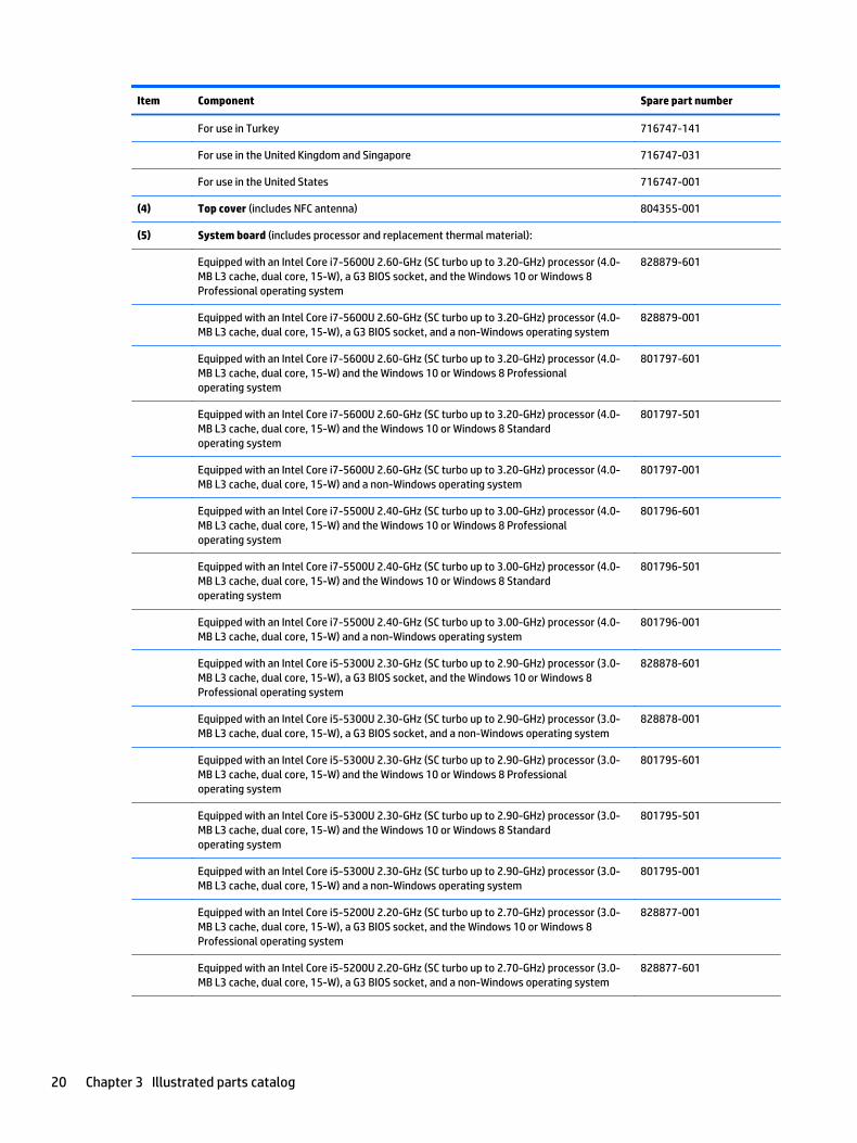
For use in Turkey 716747-141
For use in the United Kingdom and Singapore 716747-031
For use in the United States 716747-001
(4) Top cover (includes NFC antenna) 804355-001
(5) System board (includes processor and replacement thermal material):
Equipped with an Intel Core i7-5600U 2.60-GHz (SC turbo up to 3.20-GHz) processor (4.0-MB L3 cache, dual core, 15-W), a G3 BIOS socket, and the Windows 10 or Windows 8 Professional operating system
828879-601
Equipped with an Intel Core i7-5600U 2.60-GHz (SC turbo up to 3.20-GHz) processor (4.0-MB L3 cache, dual core, 15-W), a G3 BIOS socket, and a non-Windows operating system
828879-001
Equipped with an Intel Core i7-5600U 2.60-GHz (SC turbo up to 3.20-GHz) processor (4.0-MB L3 cache, dual core, 15-W) and the Windows 10 or Windows 8 Professional operating system
801797-601
Equipped with an Intel Core i7-5600U 2.60-GHz (SC turbo up to 3.20-GHz) processor (4.0-MB L3 cache, dual core, 15-W) and the Windows 10 or Windows 8 Standard operating system
801797-501
Equipped with an Intel Core i7-5600U 2.60-GHz (SC turbo up to 3.20-GHz) processor (4.0-MB L3 cache, dual core, 15-W) and a non-Windows operating system
801797-001
Equipped with an Intel Core i7-5500U 2.40-GHz (SC turbo up to 3.00-GHz) processor (4.0-MB L3 cache, dual core, 15-W) and the Windows 10 or Windows 8 Professional operating system
801796-601
Equipped with an Intel Core i7-5500U 2.40-GHz (SC turbo up to 3.00-GHz) processor (4.0-MB L3 cache, dual core, 15-W) and the Windows 10 or Windows 8 Standard operating system
801796-501
Equipped with an Intel Core i7-5500U 2.40-GHz (SC turbo up to 3.00-GHz) processor (4.0-MB L3 cache, dual core, 15-W) and a non-Windows operating system
801796-001
Equipped with an Intel Core i5-5300U 2.30-GHz (SC turbo up to 2.90-GHz) processor (3.0-MB L3 cache, dual core, 15-W), a G3 BIOS socket, and the Windows 10 or Windows 8 Professional operating system
828878-601
Equipped with an Intel Core i5-5300U 2.30-GHz (SC turbo up to 2.90-GHz) processor (3.0-MB L3 cache, dual core, 15-W), a G3 BIOS socket, and a non-Windows operating system
828878-001
Equipped with an Intel Core i5-5300U 2.30-GHz (SC turbo up to 2.90-GHz) processor (3.0-MB L3 cache, dual core, 15-W) and the Windows 10 or Windows 8 Professional operating system
801795-601
Equipped with an Intel Core i5-5300U 2.30-GHz (SC turbo up to 2.90-GHz) processor (3.0-MB L3 cache, dual core, 15-W) and the Windows 10 or Windows 8 Standard operating system
801795-501
Equipped with an Intel Core i5-5300U 2.30-GHz (SC turbo up to 2.90-GHz) processor (3.0-MB L3 cache, dual core, 15-W) and a non-Windows operating system
801795-001
Equipped with an Intel Core i5-5200U 2.20-GHz (SC turbo up to 2.70-GHz) processor (3.0-MB L3 cache, dual core, 15-W), a G3 BIOS socket, and the Windows 10 or Windows 8 Professional operating system
828877-001
Equipped with an Intel Core i5-5200U 2.20-GHz (SC turbo up to 2.70-GHz) processor (3.0-MB L3 cache, dual core, 15-W), a G3 BIOS socket, and a non-Windows operating system
828877-601
20 Chapter 3 Illustrated parts catalog

Item Component Spare part number
Equipped with an Intel Core i5-5200U 2.20-GHz (SC turbo up to 2.70-GHz) processor (3.0-MB L3 cache, dual core, 15-W) and the Windows 10 or Windows 8 Professional operating system
801794-001
Equipped with an Intel Core i5-5200U 2.20-GHz (SC turbo up to 2.70-GHz) processor (3.0-MB L3 cache, dual core, 15-W) and the Windows 10 or Windows 8 Standard operating system
801794-501
Equipped with an Intel Core i5-5200U 2.20-GHz (SC turbo up to 2.70-GHz) processor (3.0-MB L3 cache, dual core, 15-W) and a non-Windows operating system
801794-601
Equipped with an Intel Core i3-5010U 2.10-GHz processor (3.0-MB L3 cache, dual core, 15-W) and the Windows 10 or Windows 8 Professional operating system
801793-601
Equipped with an Intel Core i3-5010U 2.10-GHz processor (3.0-MB L3 cache, dual core, 15-W) and the Windows 10 or Windows 8 Standard operating system
801793-501
Equipped with an Intel Core i3-5010U 2.10-GHz processor (3.0-MB L3 cache, dual core, 15-W) and a non-Windows operating system
801793-001
(6) Fan/heat sink assembly (includes replacement thermal material) 801798-001
(7) RTC battery (includes cable and double-sided adhesive) 716742-001
(8) Bottom cover (includes battery release latch) 753715-001
(9) Power Button board (includes cable) 753718-001
(10) Speaker Kit (includes left and right speakers and cables) 753719-001
(11) NFC board (includes cable) 801800-001
(12) Solid-state drive:
512-MB, M2, SATA-3 796427-001
256-MB, M2, SATA-3 804358-001
256-MB, M2, SATA-3, SED, Opal 2 785503-001
256-MB, M2, SATA-3, SED, Opal 2, Locked 834420-001
256-MB, M2, SATA-3, TLC 804361-001
180-MB, M2, SATA-3 753730-001
180-MB, M2, SATA-3, SED, Opal 2 804357-001
128-MB, M2, SATA-3 804356-001
128-MB, M2, SATA-3, TLC 804360-001
(13) Memory module (PC3L, 12800, 1600):
8-GB 693374-001
4-GB 691740-001
(14) WWAN module:
HP lt4211 LTE/EV-DO/HSPA+ 4G Module 793116-001
HP lt4112 LTE/HSPA+ 4G Module 790198-001
HP hs3110 HSPA+ Mobile Broadband Module 822828-001
HP hs3110 HSPA+ Mobile Broadband Module 793516-001
Computer major components 21

Item Component Spare part number
(15) WLAN module:
Intel 7265.NGWGQ.I 2 ac 2×2 + Bluetooth 4.0 LE PCIe+USB NGFF 2230 INDO 756749-001
Intel 7265.NGWGQ.I 2 ac 2×2 + Bluetooth 4.0 LE PCIe+USB NGFF 2230 INDO 783721-001
Intel Dual Band Wireless-N 7265AN 802.11 a/b/g/n 2×2 WiFi + BT 4.0 Combo Adapter 756748-001
(16) Service cover (includes 6 captive retention screws and 2 rubber feet):
With icons 753713-001
Without icons 799568-001
Plastics/Rubber Kit (not illustrated, includes 4 service cover rubber screw covers) 716744-001
(17) 6-cell, 44-Wh, 1.98-Ah, Li-ion battery (includes rubber feet and speaker grilles) 698943-001
Miscellaneous parts
Component Spare part number
AC adapter:
90-W HP Smart travel AC adapter (3-wire) 616072-001
65-W HP Smart AC adapter (RC, V, EM, 3-wire) 693710-001
45-W HP Smart AC adapter (non-PFC, RC, 3-wire) 744893-001
Power cord (3-pin, black, 1.83-m):
For use in Argentina 490371-D01
For use in Australia 490371-011
For use in Brazil 490371-202
For use in Denmark 490371-081
For use in Europe 490371-021
For use in India 490371-D61
For use in Israel 490371-BB1
For use in Italy 490371-061
For use in Japan 490371-291
For use in North America 490371-001
For use in the People's Republic of China 490371-AA1
For use in South Africa 490371-AR1
For use in South Korea 490371-AD1
For use in Switzerland 490371-111
For use in Taiwan 490371-AB1
For use in Thailand 490371-201
22 Chapter 3 Illustrated parts catalog

Component Spare part number
For use in the United Kingdom and Singapore 490371-031
Power cord (3-pin, black, 1.00-m):
For use in Argentina 755530-D01
For use in Australia 755530-011
For use in Brazil 755530-202
For use in Denmark 755530-081
For use in Europe 755530-021
For use in India 755530-D61
For use in Israel 755530-BB1
For use in Italy 755530-061
For use in Japan 755530-291
For use in North America 755530-001
For use in the People's Republic of China 755530-AA1
For use in South Africa 755530-AR1
For use in South Korea 755530-AD1
For use in Switzerland 755530-111
For use in Taiwan 755530-AB1
For use in Thailand 755530-201
For use in the United Kingdom and Singapore 755530-031
Screw Kit 753731-001
Miscellaneous parts 23

4 Removal and replacement procedures preliminary requirements
Tools requiredYou will need the following tools to complete the removal and replacement procedures:
● Flat-bladed screwdriver
● Magnetic screwdriver
● Phillips P0 and P1 screwdrivers
Service considerationsThe following sections include some of the considerations that you must keep in mind during disassembly and assembly procedures.
NOTE: As you remove each subassembly from the computer, place the subassembly (and all accompanying screws) away from the work area to prevent damage.
Plastic parts
CAUTION: Using excessive force during disassembly and reassembly can damage plastic parts. Use care when handling the plastic
24 Chapter 4 Removal and replacement procedures preliminary requirements

Cables and connectors
CAUTION: When servicing the computer, be sure that cables are placed in their proper locations during the reassembly process. Improper cable placement can damage the computer.
Cables must be handled with extreme care to avoid damage. Apply only the tension required to unseat or seat the cables during removal and insertion. Handle cables by the connector whenever possible. In all cases, avoid bending, twisting, or tearing cables. Be sure that cables are routed in such a way that they cannot be caught or snagged by parts being removed or replaced. Handle flex cables with extreme care; these cables tear easily.
Drive handling
CAUTION: Drives are fragile components that must be handled with care. To prevent damage to the computer, damage to a drive, or loss of information, observe these precautions:
Before removing or inserting a hard drive, shut down the computer. If you are unsure whether the computer is off or in Hibernation, turn the computer on, and then shut it down through the operating system.
Before handling a drive, be sure that you are discharged of static electricity. While handling a drive, avoid touching the connector.
Before removing a diskette drive or optical drive, be sure that a diskette or disc is not in the drive and be sure that the optical drive tray is closed.
Handle drives on surfaces covered with at least one inch of shock-proof foam.
Avoid dropping drives from any height onto any surface.
Avoid exposing an internal hard drive to products that have magnetic fields, such as monitors or speakers.
Avoid exposing an internal hard drive to products that have magnetic fields, such as monitors or speakers.
Avoid exposing a drive to temperature extremes or liquids.
If a drive must be mailed, place the drive in a bubble pack mailer or other suitable form of protective packaging and label the package “FRAGILE.”
Service considerations 25

Grounding guidelines
Electrostatic discharge damage
Electronic components are sensitive to electrostatic discharge (ESD). Circuitry design and structure determine the degree of sensitivity. Networks built into many integrated circuits provide some protection, but in many cases, ESD contains enough power to alter device parameters or melt silicon junctions.
A discharge of static electricity from a finger or other conductor can destroy static-sensitive devices or microcircuitry. Even if the spark is neither felt nor heard, damage may have occurred.
An electronic device exposed to ESD may not be affected at all and can work perfectly throughout a normal cycle. Or the device may function normally for a while, then degrade in the internal layers, reducing its life expectancy.
CAUTION: To prevent damage to the computer when you are removing or installing internal components, observe these precautions:
Keep components in their electrostatic-safe containers until you are ready to install them.
Before touching an electronic component, discharge static electricity by using the guidelines described in this section.
Avoid touching pins, leads, and circuitry. Handle electronic components as little as possible.
If you remove a component, place it in an electrostatic-safe container.
The following table shows how humidity affects the electrostatic voltage levels generated by different activities.
CAUTION: A product can be degraded by as little as 700 V.
Typical electrostatic voltage levels
Relative humidity
Event 10% 40% 55%
Walking across carpet 35,000 V 15,000 V 7,500 V
Walking across vinyl floor 12,000 V 5,000 V 3,000 V
Motions of bench worker 6,000 V 800 V 400 V
Removing DIPS from plastic tube 2,000 V 700 V 400 V
Removing DIPS from vinyl tray 11,500 V 4,000 V 2,000 V
Removing DIPS from Styrofoam 14,500 V 5,000 V 3,500 V
Removing bubble pack from PCB 26,500 V 20,000 V 7,000 V
Packing PCBs in foam-lined box 21,000 V 11,000 V 5,000 V
26 Chapter 4 Removal and replacement procedures preliminary requirements

Packaging and transporting guidelines
Follow these grounding guidelines when packaging and transporting equipment:
● To avoid hand contact, transport products in static-safe tubes, bags, or boxes.
● Protect ESD-sensitive parts and assemblies with conductive or approved containers or packaging.
● Keep ESD-sensitive parts in their containers until the parts arrive at static-free workstations.
● Place items on a grounded surface before removing items from their containers.
● Always be properly grounded when touching a component or assembly.
● Store reusable ESD-sensitive parts from assemblies in protective packaging or nonconductive foam.
● Use transporters and conveyors made of antistatic belts and roller bushings. Be sure that mechanized equipment used for moving materials is wired to ground and that proper materials are selected to avoid static charging. When grounding is not possible, use an ionizer to dissipate electric charges.
Workstation guidelines
Follow these grounding workstation guidelines:
● Cover the workstation with approved static-shielding material.
● Use a wrist strap connected to a properly grounded work surface and use properly grounded tools and equipment.
● Use conductive field service tools, such as cutters, screwdrivers, and vacuums.
● When fixtures must directly contact dissipative surfaces, use fixtures made only of static safe materials.
● Keep the work area free of nonconductive materials, such as ordinary plastic assembly aids and Styrofoam.
● Handle ESD-sensitive components, parts, and assemblies by the case or PCM laminate. Handle these items only at static-free workstations.
● Avoid contact with pins, leads, or circuitry.
● Turn off power and input signals before inserting or removing connectors or test equipment.
Grounding guidelines 27
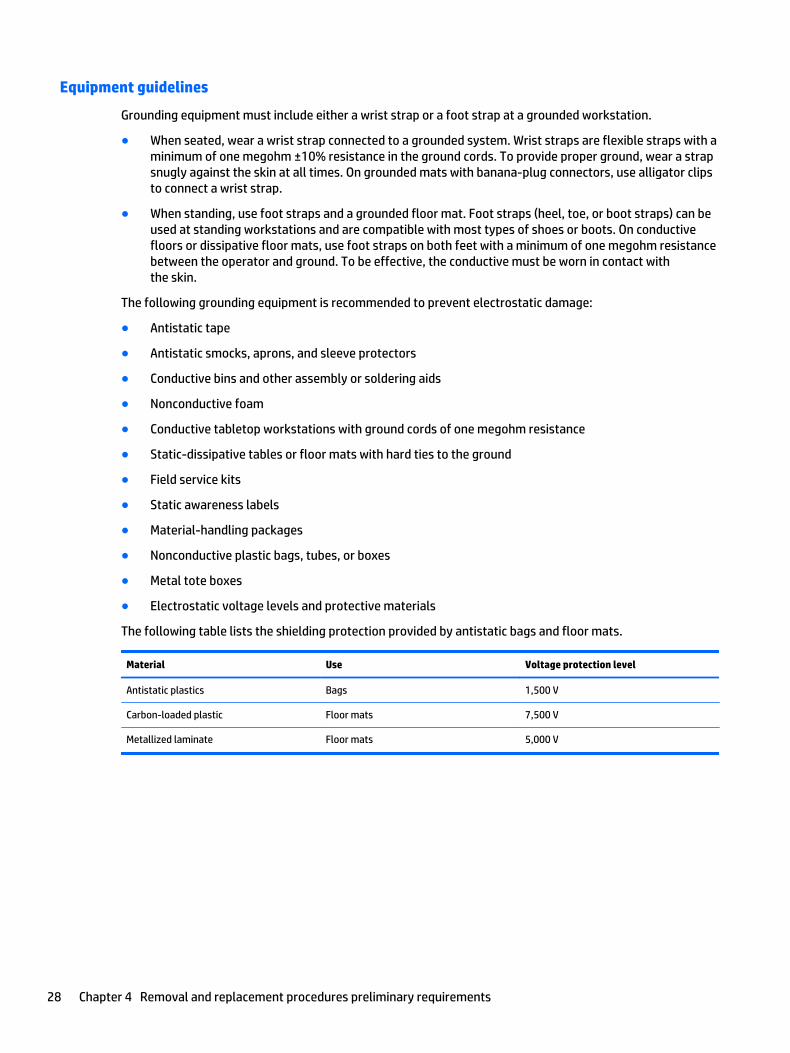
Equipment guidelines
Grounding equipment must include either a wrist strap or a foot strap at a grounded workstation.
● When seated, wear a wrist strap connected to a grounded system. Wrist straps are flexible straps with a minimum of one megohm ±10% resistance in the ground cords. To provide proper ground, wear a strap snugly against the skin at all times. On grounded mats with banana-plug connectors, use alligator clips to connect a wrist strap.
● When standing, use foot straps and a grounded floor mat. Foot straps (heel, toe, or boot straps) can be used at standing workstations and are compatible with most types of shoes or boots. On conductive floors or dissipative floor mats, use foot straps on both feet with a minimum of one megohm resistance between the operator and ground. To be effective, the conductive must be worn in contact with the skin.
The following grounding equipment is recommended to prevent electrostatic damage:
● Antistatic tape
● Antistatic smocks, aprons, and sleeve protectors
● Conductive bins and other assembly or soldering aids
● Nonconductive foam
● Conductive tabletop workstations with ground cords of one megohm resistance
● Static-dissipative tables or floor mats with hard ties to the ground
● Field service kits
● Static awareness labels
● Material-handling packages
● Nonconductive plastic bags, tubes, or boxes
● Metal tote boxes
● Electrostatic voltage levels and protective materials
The following table lists the shielding protection provided by antistatic bags and floor mats.
Material Use Voltage protection level
Antistatic plastics Bags 1,500 V
Carbon-loaded plastic Floor mats 7,500 V
Metallized laminate Floor mats 5,000 V
28 Chapter 4 Removal and replacement procedures preliminary requirements

5 Removal and replacement procedures for Customer Self-Repair parts
NOTE: The Customer Self-Repair program is not available in all locations. Installing a part not supported by the Customer Self-Repair program may void your warranty. Check your warranty to determine if Customer Self-Repair is supported in your location.
Component replacement proceduresNOTE: Please read and follow the procedures described here to access and replace Customer Self-Repair parts successfully.
NOTE: Details about your computer, including model, serial number, product key, and length of warranty, are on the service tag at the bottom of your computer.
This chapter provides removal and replacement procedures for Customer Self-Repair parts.
There are as many as 11 screws that must be removed, replaced, and/or loosened when servicing Customer Self-Repair parts. Make special note of each screw size and location during removal and replacement.
Battery
Description Spare part number
6 cell, 44-Wh, 1.98-Ah, Li-ion battery (includes rubber feet and speaker grilles) 698943-001
Before disassembling the computer, follow these steps:
1. Turn off the computer. If you are unsure whether the computer is off or in Hibernation, turn the computer on, and then shut it down through the operating system.
2. Disconnect the power from the computer by unplugging the power cord from the computer.
3. Disconnect all external devices from the computer.
Remove the battery:
1. Turn the computer upside down with the rear toward you.
2. Slide the battery release latch (1) to release the battery.
Component replacement procedures 29

3. Pivot the battery up and back and then remove the battery (2).
Reverse this procedure to install the battery.
Service cover
NOTE: The service cover spare part kit includes 6 captive retention screws and 2 rubber feet.
Description Spare part number
With icons 753713-001
Without icons 799568-001
Before removing the service cover, follow these steps:
1. Turn off the computer. If you are unsure whether the computer is off or in Hibernation, turn the computer on, and then shut it down through the operating system.
2. Disconnect the power from the computer by unplugging the power cord from the computer.
3. Disconnect all external devices from the computer.
4. Remove the battery (see Battery on page 29).
Remove the service cover:
1. Press on the memory card bezel (1) once to release the bezel, and then press on the bezel again to remove the bezel.
2. Remove the two large rubber screw covers (2).
3. Remove the two small rubber screw covers (3).
The large and small rubber screw covers are included in the Plastics/Rubber Kit, spare part number 716744-001.
30 Chapter 5 Removal and replacement procedures for Customer Self-Repair parts

4. Remove the two Phillips PM2.0×8.5 screws (4) that secure the service cover to the computer.
5. Loosen the four captive Phillips screws (1) on the front edge of the service cover.
6. Loosen the two captive Phillips screws (2) on the rear edge of the service cover.
7. Lift the front edge of the service cover (3) until the cover detaches from the computer, and then remove the service cover (4) from the computer.
Reverse this procedure to install the service cover.
Component replacement procedures 31

WWAN module
Description Spare part number
HP lt4211 LTE/EV-DO/HSPA+ 4G Module 793116-001
HP lt4112 LTE/HSPA+ 4G Module 790198-001
HP hs3110 HSPA+ Mobile Broadband Module 822828-001
HP hs3110 HSPA+ Mobile Broadband Module 793516-001
CAUTION: To prevent an unresponsive system, replace the wireless module only with a wireless module authorized for use in the computer by the governmental agency that regulates wireless devices in your country or region. If you replace the module and then receive a warning message, remove the module to restore device functionality, and then contact technical support.
Before removing the WWAN module, follow these steps:
1. Turn off the computer. If you are unsure whether the computer is off or in Hibernation, turn the computer on, and then shut it down through the operating system.
2. Disconnect the power from the computer by unplugging the power cord from the computer.
3. Disconnect all external devices from the computer.
4. Remove the battery (see Battery on page 29).
5. Remove the service cover (see Service cover on page 30).
Remove the WWAN module:
1. Disconnect the WWAN antenna cables (1) from the terminals on the WWAN module.
NOTE: The WWAN antenna cable labeled “5/MAIN” connects to the WWAN module “Main” terminal. The WWAN antenna cable labeled “6/AUX” connects to the WWAN module “Aux” terminal.
2. Remove the Phillips PM2.0×3.0 screw (2) that secures the WWAN module to the computer. (The WWAN module tilts up.)
32 Chapter 5 Removal and replacement procedures for Customer Self-Repair parts

3. Remove the WWAN module (3) by pulling the module away from the slot at an angle.
NOTE: If the WWAN antenna cables are not connected to the WWAN module terminal, the protective sleeves should be installed on the antenna connectors, as shown in the following illustration.
Reverse this procedure to install the WWAN module.
Component replacement procedures 33
WLAN module
Description Spare part number
Intel 7265.NGWGQ.I 2 ac 2×2 + Bluetooth 4.0 LE PCIe+USB NGFF 2230 INDO 756749-001
Intel 7265.NGWGQ.I 2 ac 2×2 + Bluetooth 4.0 LE PCIe+USB NGFF 2230 INDO 783721-001
Intel Dual Band Wireless-N 7265AN 802.11 a/b/g/n 2×2 WiFi + BT 4.0 Combo Adapter 756748-001
CAUTION: To prevent an unresponsive system, replace the wireless module only with a wireless module authorized for use in the computer by the governmental agency that regulates wireless devices in your country or region. If you replace the module and then receive a warning message, remove the module to restore device functionality, and then contact technical support.
Before removing the WLAN module, follow these steps:
1. Turn off the computer. If you are unsure whether the computer is off or in Hibernation, turn the computer on, and then shut it down through the operating system.
2. Disconnect the power from the computer by unplugging the power cord from the computer.
3. Disconnect all external devices from the computer.
4. Remove the battery (see Battery on page 29).
5. Remove the service cover (see Service cover on page 30).
Remove the WLAN module:
1. Disconnect the WLAN connector from the computer.
2. Disconnect the WLAN antenna cables (1) from the WLAN module terminals.
NOTE: The WLAN antenna cable labeled “1/MAIN” connects to the WLAN module “Main” terminal. The WLAN antenna cable labeled “2/AUX” connects to the WLAN module “Aux” terminal.
3. Remove the Phillips PM2.0×2.5 screw (2) that secures the WLAN module to the system board. (The WLAN module tilts up.)
34 Chapter 5 Removal and replacement procedures for Customer Self-Repair parts
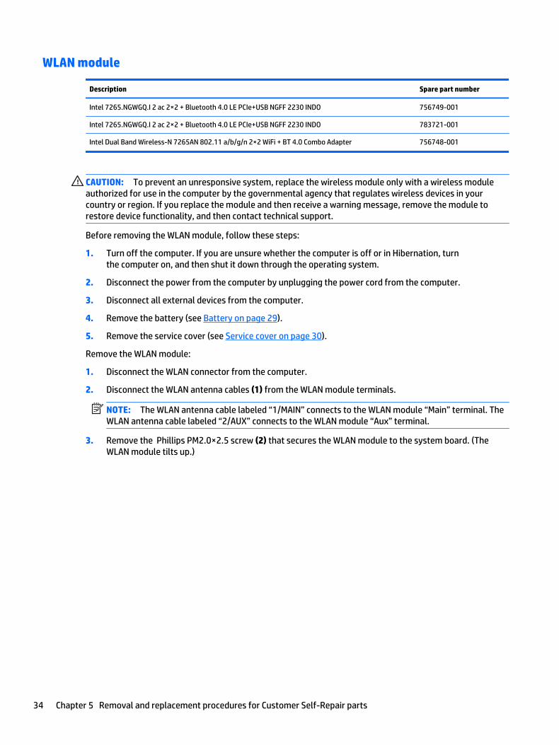
4. Remove the WLAN module (3) by pulling the module away from the connection at an angle.
NOTE: If the WLAN antennas are not connected to the WLAN module, the protective sleeve should be installed on the antenna connectors, as shown in the following illustration.
Reverse this procedure to install the WLAN module.
Component replacement procedures 35

Solid-state drive
Description Spare part number
512-MB, M2, SATA-3 796427-001
256-MB, M2, SATA-3 804358-001
256-MB, M2, SATA-3, SED, Opal 2 785503-001
256-MB, M2, SATA-3, SED, Opal 2, Locked 834420-001
256-MB, M2, SATA-3, TLC 804361-001
180-MB, M2, SATA-3 753730-001
180-MB, M2, SATA-3, SED, Opal 2 804357-001
128-MB, M2, SATA-3 804356-001
128-MB, M2, SATA-3, TLC 804360-001
Before removing the solid-state drive, follow these steps:
1. Turn off the computer. If you are unsure whether the computer is off or in Hibernation, turn the computer on, and then shut it down through the operating system.
2. Disconnect the power from the computer by unplugging the power cord from the computer.
3. Disconnect all external devices from the computer.
4. Remove the battery (see Battery on page 29).
5. Remove the service cover (see Service cover on page 30).
Remove the solid-state drive:
1. Remove the Phillips PM2.0×3.0 screw (1) that secures the solid-state drive to the computer. (The solid-state drive tilts up.)
36 Chapter 5 Removal and replacement procedures for Customer Self-Repair parts
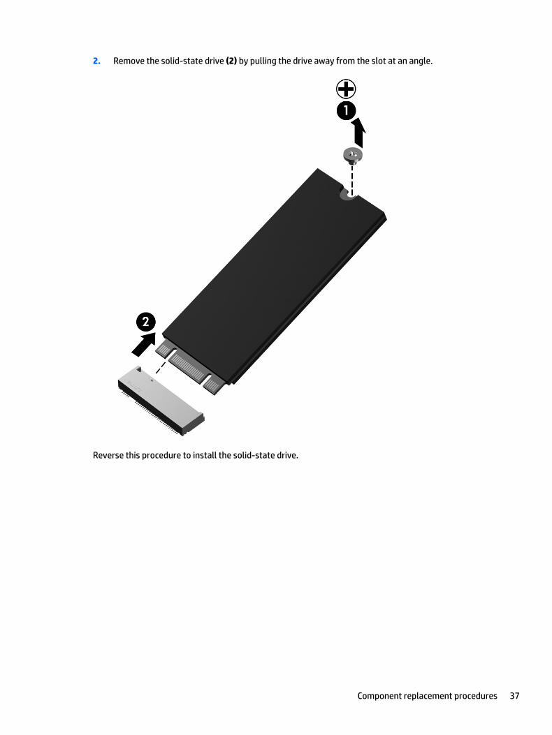
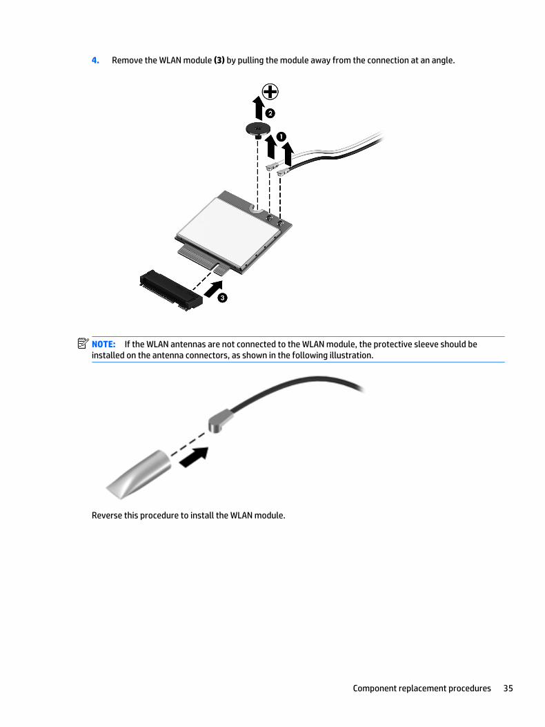
2. Remove the solid-state drive (2) by pulling the drive away from the slot at an angle.
Reverse this procedure to install the solid-state drive.
Component replacement procedures 37

Memory module
Description Spare part number
8 GB memory module (PC3, 12800, 1600) 693374-001
4 GB memory module PC3L 12800 1600) 691740-001
Before removing a memory module, follow these steps:
1. Turn off the computer. If you are unsure whether the computer is off or in Hibernation, turn the computer on, and then shut it down through the operating system.
2. Disconnect the power from the computer by unplugging the power cord from the computer.
3. Disconnect all external devices from the computer.
4. Remove the battery (see Battery on page 29).
5. Remove the service cover (see Service cover on page 30).
Remove the memory module:
NOTE: Note the location of the memory module. If you are replacing it, install the new memory module in the same slot.
1. Spread the two retaining tabs (1) on each side of the memory module slot to release the memory module. (The memory module tilts up.)
2. Remove the memory module (2) by pulling it away from the slot at a 45 degree angle.
Reverse this procedure to install the memory module.
38 Chapter 5 Removal and replacement procedures for Customer Self-Repair parts

6 Removal and replacement procedures for Authorized Service Provider parts
CAUTION: Components described in this chapter should only be accessed by an authorized service provider. Accessing these parts can damage the computer or void the warranty.
Component replacement proceduresNOTE: Details about your computer, including model, serial number, product key, and length of warranty, are on the service tag at the bottom of your computer. See Bottom on page 16 for details.
This chapter provides removal and replacement procedures for Authorized Service Provider only parts.
There are as many as 32 screws that must be removed, replaced, and/or loosened when servicing Authorized Service Provider only parts. Make special note of each screw size and location during removal and replacement.
Unlocking the device and disabling Always On Remote Management (select HP devices only)
HP Touchpoint Manager (HPTM) is a complete cloud-based solution for managing devices. For select HP devices with the Windows operating system, the Always On Remote Management (AORM) feature is automatically activated when HP Touchpoint Manager software is installed.
AORM can perform a secure BIOS level lock and can also securely erase internal drives (except for encrypted self-encrypting drives). The HP Touchpoint Manager website (http://www.hptouchpointmanager.com) provides access to the AORM lock feature. The device must be unlocked using an authorized PIN from the same website before you can access HP Computer Setup and start the Windows operating system.
IMPORTANT: A service agent cannot retrieve the PIN from the HP Touchpoint Manager website. If a locked device is returned for service, the agent must contact the customer to obtain the PIN to unlock the device. If a PIN is not available, the entire system board must be replaced.
Before returning the device for service, be sure to unlock the device using the PIN from the HP Touchpoint Manager website (http://www.hptouchpointmanager.com), and also disable the AORM feature in HP Computer Setup.
To disable AORM:
1. Access HP Computer Setup (F10).
a. Turn on or restart the device, and then press esc while the “Press the ESC key for Startup Menu” message is displayed at the bottom of the screen.
b. Press f10 to enter Computer Setup.
NOTE: If the BIOS is protected with an Administrator password, enter the password.
2. Select Advanced, and then select HP Touchpoint Manager Options.
Component replacement procedures 39

3. Clear the Allow Activation check box.
4. Select Save changes and exit.
NFC board
Description Spare part number
NFC board (includes NFC board cable) 801800-001
Before removing the NFC board, follow these steps:
1. Turn off the computer. If you are unsure whether the computer is off or in Hibernation, turn the computer on, and then shut it down through the operating system.
2. Disconnect the power from the computer by unplugging the power cord from the computer.
3. Disconnect all external devices from the computer.
4. Remove the battery (see Battery on page 29).
5. Remove the service cover (see Service cover on page 30).
Remove the NFC board:
1. Release the zero insertion force (ZIF) connector (1) to which the NFC board cable is attached, and then disconnect the NFC board cable from the NFC board (2).
2. Remove the Phillips M1.5×2.0 screw (3) that secures the NFC board to the bottom cover.
3. Detach the NFC board (4) from the bottom cover. (The NFC board is attached to the bottom cover with double-sided tape.)
4. Remove the NFC board and cable.
40 Chapter 6 Removal and replacement procedures for Authorized Service Provider parts
Reverse this procedure to install the NFC board and cable.
Keyboard
NOTE: The keyboard spare part kit includes a backlight cable and keyboard cable.
For use in country/region Spare part number For use in country/region Spare part number
For use in Belgium 716747-A41 For use in Norway 716747-091
For use in Brazil 716747-201 For use in Northwest Africa 716747-FP1
For use in Bulgaria 716747-261 For use in Portugal 716747-131
For use in Canada 716747-DB1 For use in Romania 716747-271
For use in the Czech Republic and Slovakia
716747-FL1 For use in Russia 716747-251
For use in Denmark 716747-081 For use in Saudi Arabia 716747-171
For use in France 716747-051 For use in Slovenia 716747-BA1
For use in Germany 716747-041 For use in South Korea 716747-AD1
For use in Greece 716747-151 For use in Spain 716747-071
For use in Hungary 716747-211 For use in Sweden and Finland 716747-B71
For use in Iceland 716747-DD1 For use in Switzerland 716747-BG1
For use in India 716747-D61 For use in Taiwan 716747-AB1
For use in Israel 716747-BB1 For use in Thailand 716747-281
For use in Italy 716747-061 For use in Turkey 716747-141
For use in Japan 716747-291 For use in the United Kingdom and Singapore
716747-031
For use in Latin America 716747-161 For use in the United States 716747-001
For use in the Netherlands 716747-B31
Before removing the keyboard, follow these steps:
1. Turn off the computer. If you are unsure whether the computer is off or in Hibernation, turn the computer on, and then shut it down through the operating system.
2. Disconnect the power from the computer by unplugging the power cord from the computer.
3. Disconnect all external devices from the computer.
4. Remove the battery (see Battery on page 29).
5. Remove the service cover (see Service cover on page 30).
Remove the keyboard:
1. Loosen the 2 captive screws that secure the keyboard to the computer.
Component replacement procedures 41

2. Partially open the computer.
3. Rest and secure the computer on its left side.
4. Insert a keyboard release tool or similar thin, plastic tool into the keyboard release hole near the fan, and then press on the back of the keyboard until the keyboard disengages from the computer.
5. Turn the computer right-side up with the front toward you.
42 Chapter 6 Removal and replacement procedures for Authorized Service Provider parts
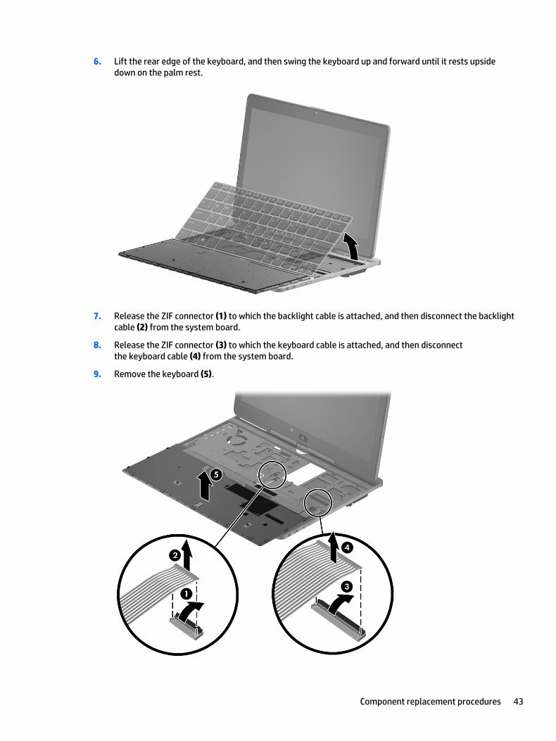
6. Lift the rear edge of the keyboard, and then swing the keyboard up and forward until it rests upside down on the palm rest.
7. Release the ZIF connector (1) to which the backlight cable is attached, and then disconnect the backlight cable (2) from the system board.
8. Release the ZIF connector (3) to which the keyboard cable is attached, and then disconnect the keyboard cable (4) from the system board.
9. Remove the keyboard (5).
Component replacement procedures 43

Reverse this procedure to install the keyboard.
Bottom cover
Description Spare part number
Bottom cover (includes battery release latch) 753715-001
Before removing the bottom cover, follow these steps:
1. Turn off the computer. If you are unsure whether the computer is off or in Hibernation, turn the computer on, and then shut it down through the operating system.
2. Disconnect the power from the computer by unplugging the power cord from the computer.
3. Disconnect all external devices from the computer.
4. Remove the battery (see Battery on page 29).
5. Remove the service cover (see Service cover on page 30).
6. Remove the keyboard (see Keyboard on page 41).
NOTE: When replacing the bottom cover, be sure that the NFC board is removed from the defective bottom cover and installed on the replacement bottom cover. See NFC board on page 40 for NFC board removal instructions.
Remove the bottom cover:
1. Remove the two Phillips PM2.0×4.4 screws that secure the bottom cover to the computer.
2. Close the computer.
3. Turn the computer upside down, with the rear toward you.
44 Chapter 6 Removal and replacement procedures for Authorized Service Provider parts

4. Release the tape (1), (2), and (3) that secures the wireless antenna cables.
5. Remove the following screws that secure the bottom cover to the computer:
(1) Six Torx T8M2.0×5.6 screws
(2) One Torx T8M2.0×3.2 screw
(3) One Phillips PM2.0×2.3 broad head screw
Component replacement procedures 45

6. Remove the bottom cover.
Reverse this procedure to install the bottom cover.
46 Chapter 6 Removal and replacement procedures for Authorized Service Provider parts

Speakers
Description Spare part number
Speaker Kit (includes left and right speakers and cables) 753719-001
Before removing the speakers, follow these steps:
1. Turn off the computer. If you are unsure whether the computer is off or in Hibernation, turn the computer on, and then shut it down through the operating system.
2. Disconnect the power from the computer by unplugging the power cord from the computer.
3. Disconnect all external devices from the computer.
4. Remove the battery (see Battery on page 29), and then remove the following components:
a. Service cover (see Service cover on page 30)
b. Keyboard (see Keyboard on page 41)
c. Bottom cover (see Bottom cover on page 44)
Remove the speakers:
1. Disconnect the speaker cables (1) from the system board.
2. Release the tape (2) that secures the left speaker cable.
3. Remove the three Phillips PM2.0×2.3 broad head screws (3) that secure the speakers to the top cover.
4. Remove the speakers (4).
Reverse this procedure to install the speakers.
Component replacement procedures 47

Power button board
Description Spare part number
Power button board (includes cable) 753718-001
Before removing the power button board, follow these steps:
1. Turn off the computer. If you are unsure whether the computer is off or in Hibernation, turn the computer on, and then shut it down through the operating system.
2. Disconnect the power from the computer by unplugging the power cord from the computer.
3. Disconnect all external devices from the computer.
4. Remove the battery (see Battery on page 29), and then remove the following components:
a. Service cover (see Service cover on page 30)
b. Keyboard (see Keyboard on page 41)
c. Bottom cover (see Bottom cover on page 44)
d. Right speaker (see Speakers on page 47)
Remove the power button board:
1. Turn the computer right side up, with the front toward you.
2. Open the computer.
3. Release the ZIF connector (1) to which the power button board cable is attached, and then disconnect the power button board cable (2) from the system board.
4. Detach the power button board (3) from the bottom cover. (The button board cable is attached to the bottom cover with double-sided tape.)
5. Close the computer.
6. Turn the computer upside down, with the rear toward you.
48 Chapter 6 Removal and replacement procedures for Authorized Service Provider parts

7. Remove the two Phillips PM2.0×2.9 screws (1) that secure the power button board to the bottom cover.
8. Remove the power button board (2).
Reverse this procedure to install the power button board.
RTC battery
Description Spare part number
RTC battery (includes cable and double-sided adhesive) 716742-001
Before removing the RTC battery, follow these steps:
1. Turn off the computer. If you are unsure whether the computer is off or in Hibernation, turn the computer on, and then shut it down through the operating system.
2. Disconnect the power from the computer by unplugging the power cord from the computer.
3. Disconnect all external devices from the computer.
4. Remove the battery (see Battery on page 29), and then remove the following components:
a. Service cover (see Service cover on page 30)
b. Keyboard (see Keyboard on page 41)
c. Bottom cover (see Bottom cover on page 44)
Remove the RTC battery:
1. Disconnect the RTC battery cable (1) from the system board.
Component replacement procedures 49

2. Detach the RTC battery (2) from the bottom cover. (The RTC battery is attached to the system board with double-sided tape.)
3. Remove the RTC battery.
Reverse this procedure to install the RTC battery.
System board
Description Spare part number
Equipped with an Intel Core i7-5600U 2.60-GHz (SC turbo up to 3.20-GHz) processor (4.0-MB L3 cache, dual core, 15-W), a G3 BIOS socket, and the Windows 10 or Windows 8 Professional operating system
828879-601
Equipped with an Intel Core i7-5600U 2.60-GHz (SC turbo up to 3.20-GHz) processor (4.0-MB L3 cache, dual core, 15-W), a G3 BIOS socket, and a non-Windows operating system
828879-001
Equipped with an Intel Core i7-5600U 2.60-GHz (SC turbo up to 3.20-GHz) processor (4.0-MB L3 cache, dual core, 15-W) and the Windows 10 or Windows 8 Professional operating system
801797-601
Equipped with an Intel Core i7-5600U 2.60-GHz (SC turbo up to 3.20-GHz) processor (4.0-MB L3 cache, dual core, 15-W) and the Windows 10 or Windows 8 Standard operating system
801797-501
Equipped with an Intel Core i7-5600U 2.60-GHz (SC turbo up to 3.20-GHz) processor (4.0-MB L3 cache, dual core, 15-W) and a non-Windows operating system
801797-001
Equipped with an Intel Core i7-5500U 2.40-GHz (SC turbo up to 3.00-GHz) processor (4.0-MB L3 cache, dual core, 15-W) and the Windows 10 or Windows 8 Professional operating system
801796-601
Equipped with an Intel Core i7-5500U 2.40-GHz (SC turbo up to 3.00-GHz) processor (4.0-MB L3 cache, dual core, 15-W) and the Windows 10 or Windows 8 Standard operating system
801796-501
Equipped with an Intel Core i7-5500U 2.40-GHz (SC turbo up to 3.00-GHz) processor (4.0-MB L3 cache, dual core, 15-W) and a non-Windows operating system
801796-001
Equipped with an Intel Core i5-5300U 2.30-GHz (SC turbo up to 2.90-GHz) processor (3.0-MB L3 cache, dual core, 15-W), a G3 BIOS socket, and the Windows 10 or Windows 8 Professional operating system
828878-601
Equipped with an Intel Core i5-5300U 2.30-GHz (SC turbo up to 2.90-GHz) processor (3.0-MB L3 cache, dual core, 15-W), a G3 BIOS socket, and a non-Windows operating system
828878-001
50 Chapter 6 Removal and replacement procedures for Authorized Service Provider parts

Description Spare part number
Equipped with an Intel Core i5-5300U 2.30-GHz (SC turbo up to 2.90-GHz) processor (3.0-MB L3 cache, dual core, 15-W) and the Windows 10 or Windows 8 Professional operating system
801795-601
Equipped with an Intel Core i5-5300U 2.30-GHz (SC turbo up to 2.90-GHz) processor (3.0-MB L3 cache, dual core, 15-W) and the Windows 10 or Windows 8 Standard operating system
801795-501
Equipped with an Intel Core i5-5300U 2.30-GHz (SC turbo up to 2.90-GHz) processor (3.0-MB L3 cache, dual core, 15-W) and a non-Windows operating system
801795-001
Equipped with an Intel Core i5-5200U 2.20-GHz (SC turbo up to 2.70-GHz) processor (3.0-MB L3 cache, dual core, 15-W), a G3 BIOS socket, and the Windows 10 or Windows 8 Professional operating system
828877-001
Equipped with an Intel Core i5-5200U 2.20-GHz (SC turbo up to 2.70-GHz) processor (3.0-MB L3 cache, dual core, 15-W), a G3 BIOS socket, and a non-Windows operating system
828877-601
Equipped with an Intel Core i5-5200U 2.20-GHz (SC turbo up to 2.70-GHz) processor (3.0-MB L3 cache, dual core, 15-W) and the Windows 10 or Windows 8 Professional operating system
801794-001
Equipped with an Intel Core i5-5200U 2.20-GHz (SC turbo up to 2.70-GHz) processor (3.0-MB L3 cache, dual core, 15-W) and the Windows 10 or Windows 8 Standard operating system
801794-501
Equipped with an Intel Core i5-5200U 2.20-GHz (SC turbo up to 2.70-GHz) processor (3.0-MB L3 cache, dual core, 15-W) and a non-Windows operating system
801794-601
Equipped with an Intel Core i3-5010U 2.10-GHz processor (3.0-MB L3 cache, dual core, 15-W) and the Windows 10 or Windows 8 Professional operating system
801793-601
Equipped with an Intel Core i3-5010U 2.10-GHz processor (3.0-MB L3 cache, dual core, 15-W) and the Windows 10 or Windows 8 Standard operating system
801793-501
Equipped with an Intel Core i3-5010U 2.10-GHz processor (3.0-MB L3 cache, dual core, 15-W) and a non-Windows operating system
801793-001
Before removing the system board, follow these steps:
1. Turn off the computer. If you are unsure whether the computer is off or in Hibernation, turn the computer on, and then shut it down through the operating system.
2. Disconnect the power from the computer by unplugging the power cord from the computer.
3. Disconnect all external devices from the computer.
4. Remove the battery (see Battery on page 29), and then remove the following components:
a. Service cover (see Service cover on page 30)
b. Solid-state drive (see Solid-state drive on page 36)
c. Keyboard (see Keyboard on page 41)
d. Bottom cover (see Bottom cover on page 44)
e. Right speaker (see Speakers on page 47)
NOTE: When replacing the system board, be sure that the following components are removed from the defective system board and installed on the replacement system board:
● WWAN module (see WWAN module on page 32)
● WLAN module (see WLAN module on page 34)
● Memory module (see Memory module on page 38)
Component replacement procedures 51

● RTC battery (see RTC battery on page 49)
● Fan/heat sink assembly (see Fan/heat sink assembly on page 53)
Remove the system board:
1. Turn the computer right side up, with the front toward you.
2. Open the computer.
3. Release the ZIF connector (1) to which the TouchPad cable is attached, and then disconnect the TouchPad cable (2) from the system board.
4. Detach the TouchPad cable (3) from the bottom cover. (The TouchPad cable is attached to the bottom cover with double-sided tape.)
5. Close the computer.
6. Turn the computer upside down with the rear toward you.
7. Disconnect the display panel cable (1) from the system board.
8. Remove the Phillips PPM2.0×2.9 screw (2) and the Phillips PPM2.0×2.3 broad head screw (3) that secure the system board to the top cover.
52 Chapter 6 Removal and replacement procedures for Authorized Service Provider parts

9. Remove the system board (4).
Reverse this procedure to install the system board.
Fan/heat sink assembly
Description Spare part number
Fan/heat sink assembly (includes replacement thermal material) 801798-001
Before removing the fan/heat sink assembly, follow these steps:
1. Turn off the computer. If you are unsure whether the computer is off or in Hibernation, turn the computer on, and then shut it down through the operating system.
2. Disconnect the power from the computer by unplugging the power cord from the computer.
3. Disconnect all external devices from the computer.
4. Remove the battery (see Battery on page 29), and then remove the following components:
a. Service cover (see Service cover on page 30)
b. Keyboard (see Keyboard on page 41)
c. Bottom cover (see Bottom cover on page 44)
d. System board (see System board on page 50)
Remove the fan/heat sink assembly:
1. Disconnect the fan cable (1) from the system board.
2. Following the 1, 2, 3, 4 sequence stamped into the fan/heat sink assembly, loosen the four captive Phillips PM2.0×6.5 screws (2) that secure the fan/heat sink assembly to the system board.
Component replacement procedures 53

3. Remove the fan/heat sink assembly (3).
NOTE: Due to the adhesive quality of the thermal material located between the fan/heat sink assembly and the system board components, it may be necessary to move the fan/heat sink assembly from side to side to detach it.
NOTE: The thermal material must be thoroughly cleaned from the surfaces of the fan/heat sink assembly and the system board each time the fan/heat sink assembly is removed. Replacement thermal material is included with the fan/heat sink assembly and system board spare part kits. Thermal paste is used on the system board (1) and the section of the fan/heat sink assembly (2) that services it.
Reverse this procedure to install the fan/heat sink assembly.
54 Chapter 6 Removal and replacement procedures for Authorized Service Provider parts

Hinge cover
Description Spare part number
Hinge cover (includes hinge cap, WWAN antenna cables and transceivers, and WWAN antenna shield) 753714-001
Before removing the hinge cover, follow these steps:
1. Turn off the computer. If you are unsure whether the computer is off or in Hibernation, turn the computer on, and then shut it down through the operating system.
2. Disconnect the power from the computer by unplugging the power cord from the computer.
3. Disconnect all external devices from the computer.
4. Remove the battery (see Battery on page 29), and then remove the following components:
a. Service cover (see Service cover on page 30)
b. Solid-state drive (see Solid-state drive on page 36)
c. Keyboard (see Keyboard on page 41)
d. Bottom cover (see Bottom cover on page 44)
e. System board (see System board on page 50)
Remove the hinge cover:
1. Remove the shield (1) that secures the WWAN antenna cables (2) in the routing channel built into the bottom cover.
2. Remove the six Phillips PPM2.0×2.9 screws (3) that secure the hinge cover to the bottom cover.
3. Turn the computer right side up, with the front toward you.
4. Open the computer.
5. Rotate the display assembly (1) clockwise until it is perpendicular to the computer body.
Component replacement procedures 55

6. Detach the left (2) and right edges of the hinge cover from the computer.
7. Remove the hinge cover (3) by sliding it away from the computer.
8. Remove the hinge cap (4).
Reverse this procedure to install the hinge cover and hinge cap.
Display assembly
Description Spare part number
Display assembly, 11.6-in, HD, (1366×768), LED, LVDS, UWVA , ultraslim display (includes display hinge, microphone, webcam, and Windows button)
801799-001
Before removing the display assembly, follow these steps:
1. Turn off the computer. If you are unsure whether the computer is off or in Hibernation, turn the computer on, and then shut it down through the operating system.
2. Disconnect the power from the computer by unplugging the power cord from the computer.
3. Disconnect all external devices from the computer.
4. Remove the battery (see Battery on page 29), and then remove the following components:
a. Service cover (see Service cover on page 30)
b. Solid-state drive (see Solid-state drive on page 36)
c. Keyboard (see Keyboard on page 41)
d. Bottom cover (see Bottom cover on page 44)
e. System board (see System board on page 50)
f. Hinge cover and hinge cap (see Hinge cover on page 55)
Remove the display assembly:
56 Chapter 6 Removal and replacement procedures for Authorized Service Provider parts

1. Close the computer.
2. Turn the computer right side up with the rear toward you.
3. Remove the two Phillips PPM2.0×4.4 screws (1) that secure the display assembly to the bottom cover.
4. Slide the bottom cover (2) away from the display assembly.
Reverse this procedure to install the display assembly.
Component replacement procedures 57

7 Computer Setup (BIOS), TPM, and HP Sure Start – Windows 10
Using Computer SetupComputer Setup, or Basic Input/Output System (BIOS), controls communication between all the input and output devices on the system (such as disk drives, display, keyboard, mouse, and printer). Computer Setup includes settings for the types of devices installed, the startup sequence of the computer, and the amount of system and extended memory.
NOTE: Use extreme care when making changes in Computer Setup. Errors can prevent the computer from operating properly.
Starting Computer Setup
NOTE: An external keyboard or mouse connected to a USB port can be used with Computer Setup only if USB legacy support is enabled.
To start Computer Setup, follow these steps:
▲ Start Computer Setup.
● Computers or tablets with keyboards:
▲ Turn on or restart the computer, and when the HP logo appears, press f10 to enter Computer Setup.
● Tablets without keyboards:
▲ Turn off the tablet. Press the power button in combination with the volume down button until the Startup menu is displayed, and then tap F10 to enter Computer Setup.
58 Chapter 7 Computer Setup (BIOS), TPM, and HP Sure Start – Windows 10
Navigating and selecting in Computer Setup
● To select a menu or a menu item, use the tab key and the keyboard arrow keys and then press enter, or use a pointing device to select the item.
NOTE: On tablets without keyboards, you can use your finger to make selections.
● To scroll up and down, select the up arrow or the down arrow in the upper-right corner of the screen, or use the up arrow key or the down arrow key on the keyboard.
● To close open dialog boxes and return to the main Computer Setup screen, press esc, and then follow the on-screen instructions.
To exit Computer Setup menus, choose one of the following methods:
● To exit Computer Setup menus without saving your changes:
Select the Exit icon in the lower-right corner of the screen, and then follow the on-screen instructions.
‒ or –
Select Main, select Ignore Changes and Exit, and then press enter.
● To save your changes and exit Computer Setup menus:
Select the Save icon in the lower-right corner of the screen, and then follow the on-screen instructions.
‒ or –
Select Main, select Save Changes and Exit, and then press enter.
Your changes go into effect when the computer restarts.
Restoring factory settings in Computer Setup
NOTE: Restoring defaults will not change the hard drive mode.
To return all settings in Computer Setup to the values that were set at the factory, follow these steps:
1. Start Computer Setup. See Starting Computer Setup on page 58.
2. Select Main, and then select Apply Factory Defaults and Exit.
NOTE: On select products, the selections may display Restore Defaults instead of Apply Factory Defaults and Exit.
3. Follow the on-screen instructions.
4. To save your changes and exit, select the Save icon in the lower-right corner of the screen, and then follow the on-screen instructions.
‒ or –
Select Main, select Save Changes and Exit, and then press enter.
Your changes go into effect when the computer restarts.
NOTE: Your password settings and security settings are not changed when you restore the factory settings.
Using Computer Setup 59

Updating the BIOS
Updated versions of the BIOS may be available on the HP website.
Most BIOS updates on the HP website are packaged in compressed files called SoftPaqs.
Some download packages contain a file named Readme.txt, which contains information regarding installing and troubleshooting the file.
Determining the BIOS
To decide whether you need to update Computer Setup (BIOS), first determine the BIOS version on your computer.
BIOS version information (also known as ROM date and System BIOS) can be accessed by pressing fn+esc (if you are already in Windows) or by using Computer Setup.
1. Start Computer Setup. See Starting Computer Setup on page 58.
2. Select Main, and then select System Information.
3. To exit Computer Setup without saving your changes, select the Exit icon in the lower-right corner of the screen, and then follow the on-screen instructions.
‒ or –
Select Main, select Ignore Changes and Exit, and then press enter.
To check for later BIOS versions, see Downloading a BIOS update on page 60.
Downloading a BIOS update
CAUTION: To reduce the risk of damage to the computer or an unsuccessful installation, download and install a BIOS update only when the computer is connected to reliable external power using the AC adapter. Do not download or install a BIOS update while the computer is running on battery power, docked in an optional docking device, or connected to an optional power source. During the download and installation, follow these instructions:
Do not disconnect power on the computer by unplugging the power cord from the AC outlet.
Do not shut down the computer or initiate Sleep.
Do not insert, remove, connect, or disconnect any device, cable, or cord.
1. Type support in the taskbar search box, and then select the HP Support Assistant app.
‒ or –
Select the question mark icon in the taskbar.
2. Select Updates, and then select Check for updates and messages.
3. Follow the on-screen instructions.
4. At the download area, follow these steps:
a. Identify the most recent BIOS update and compare it to the BIOS version currently installed on your computer. Make a note of the date, name, or other identifier. You may need this information to locate the update later, after it has been downloaded to your hard drive.
b. Follow the on-screen instructions to download your selection to the hard drive.
Make a note of the path to the location on your hard drive where the BIOS update is downloaded. You will need to access this path when you are ready to install the update.
60 Chapter 7 Computer Setup (BIOS), TPM, and HP Sure Start – Windows 10

NOTE: If you connect your computer to a network, consult the network administrator before installing any software updates, especially system BIOS updates.
BIOS installation procedures vary. Follow any instructions that are revealed on the screen after the download is complete. If no instructions are revealed, follow these steps:
1. Type file in the taskbar search box, and then select File Explorer.
2. Select your hard drive designation. The hard drive designation is typically Local Disk (C:).
3. Using the hard drive path you recorded earlier, open the folder that contains the update.
4. Double-click the file that has an .exe extension (for example, filename.exe).
The BIOS installation begins.
5. Complete the installation by following the on-screen instructions.
NOTE: After a message on the screen reports a successful installation, you can delete the downloaded file from your hard drive.
Changing the boot order using the f9 prompt
To dynamically choose a boot device for the current startup sequence, follow these steps:
1. Access the Boot Device Options menu:
● Computers or tablets with keyboards:
▲ Turn on or restart the computer, and when the HP logo appears, press f9 to enter the Boot Device Options menu.
● Tablets without keyboards:
▲ Turn off the tablet. Press the power button in combination with the volume down button until the Startup menu is displayed, and then tap F9 to enter the Boot Device Options menu.
2. Select a boot device, then press enter.
Using Computer Setup 61

TPM BIOS settings (select products only)IMPORTANT: Before enabling Trusted Platform Module (TPM) functionality on this system, you must ensure that your intended use of TPM complies with relevant local laws, regulations and policies, and approvals or licenses must be obtained if applicable. For any compliance issues arising from your operation/usage of TPM which violates the above mentioned requirement, you shall bear all the liabilities wholly and solely. HP will not be responsible for any related liabilities.
TPM provides additional security for your computer. You can modify the TPM settings in Computer Setup (BIOS).
NOTE: If you change the TPM setting to Hidden, TPM is not visible in the operating system.
To access TPM settings in Computer Setup:
1. Start Computer Setup. See Starting Computer Setup on page 58.
2. Select Security, select TPM Embedded Security, and then follow the on-screen instructions.
Using HP Sure Start (select products only)Select computer models are configured with HP Sure Start, a technology that continuously monitors the computer's BIOS for attacks or corruption. If the BIOS becomes corrupted or is attacked, HP Sure Start automatically restores the BIOS to its previously safe state, without user intervention.
HP Sure Start is configured and already enabled so that most users can use the HP Sure Start default configuration. The default configuration can be customized by advanced users.
To access the latest documentation on HP Sure Start, go to http://www.hp.com/support, and select your country. Select Drivers & Downloads, and then follow the on-screen instructions.
62 Chapter 7 Computer Setup (BIOS), TPM, and HP Sure Start – Windows 10

8 HP PC Hardware Diagnostics (UEFI) – Windows 10
HP PC Hardware Diagnostics is a Unified Extensible Firmware Interface (UEFI) that allows you to run diagnostic tests to determine whether the computer hardware is functioning properly. The tool runs outside the operating system so that it can isolate hardware failures from issues that are caused by the operating system or other software components.
NOTE: To start BIOS on a convertible computer, your computer must be in notebook mode and you must use the keyboard attached to your tablet. The on-screen keyboard, which displays in tablet mode, cannot access BIOS.
To start HP PC Hardware Diagnostics UEFI:
1. Start BIOS:
● Computers or tablets with keyboards:
▲ Turn on or restart the computer, quickly press esc.
● Tablets without keyboards:
▲ Turn on or restart the tablet, and then quickly hold down the volume down button.
‒ or –
Turn on or restart the tablet, and then quickly hold down the Windows button.
2. Press or tap f2.
The BIOS searches three places for the diagnostic tools, in the following order:
a. Connected USB drive
NOTE: To download the HP PC Hardware Diagnostics (UEFI) tool to a USB drive, see Downloading HP PC Hardware Diagnostics (UEFI) to a USB device on page 64.
b. Hard drive
c. BIOS
3. When the diagnostic tool opens, select the type of diagnostic test you want to run, and then follow the on-screen instructions. On a tablet, press the volume down button to stop a diagnostic test.
NOTE: If you need to stop a diagnostic test on computers or tablets with a keyboard, press esc.
63

Downloading HP PC Hardware Diagnostics (UEFI) to a USB deviceThere are two options to download HP PC Hardware Diagnostics to a USB device:
Download the latest UEFI version:
1. Go to http://www.hp.com/go/techcenter/pcdiags. The HP PC Diagnostics home page is displayed.
2. In the HP PC Hardware Diagnostics section, click the Download link, and then select Run.
Download any version of UEFI for a specific product:
1. Go to http://www.hp.com/support, and then select your country. The HP Support page is displayed.
2. Click Drivers & Downloads.
3. In the text box, enter the product name, and then click Go.
– or –
Click Find Now to let HP automatically detect your product.
4. Select your computer, and then select your operating system.
5. In the Diagnostic section, follow the on-screen instructions to select and download the UEFI version you want.
64 Chapter 8 HP PC Hardware Diagnostics (UEFI) – Windows 10
9 Computer Setup (BIOS), MultiBoot, and HP PC Hardware Diagnostics (UEFI) – Windows 8
Using Computer SetupComputer Setup, or Basic Input/Output System (BIOS), controls communication between all the input and output devices on the system (such as disk drives, display, keyboard, mouse, and printer). Computer Setup includes settings for the types of devices installed, the startup sequence of the computer, and the amount of system and extended memory.
NOTE: Use extreme care when making changes in Computer Setup. Errors can prevent the computer from operating properly.
Starting Computer Setup
NOTE: An external keyboard or mouse connected to a USB port can be used with Computer Setup only if USB legacy support is enabled.
To start Computer Setup, follow these steps:
1. Turn on or restart the computer, and then press esc while the “Press the ESC key for Startup Menu” message is displayed at the bottom of the screen.
2. Press f10 to enter Computer Setup.
Navigating and selecting in Computer Setup
To navigate and select in Computer Setup, follow these steps:
1. Turn on or restart the computer, and then press esc while the “Press the ESC key for Startup Menu” message is displayed at the bottom of the screen.
NOTE: You can use either a pointing device (TouchPad, pointing stick, or USB mouse) or the keyboard to navigate and make selections in Computer Setup.
2. Press f10 to enter Computer Setup.
● To select a menu or a menu item, use the tab key and the keyboard arrow keys and then press enter, or use a pointing device to click the item.
● To scroll up and down, click the up arrow or the down arrow in the upper-right corner of the screen, or use the up arrow key or the down arrow key on the keyboard.
● To close open dialog boxes and return to the main Computer Setup screen, press esc, and then follow the on-screen instructions.
To exit Computer Setup menus, choose one of the following methods:
● To exit Computer Setup menus without saving your changes:
Click the Exit icon in the lower-right corner of the screen, and then follow the on-screen instructions.
Using Computer Setup 65

– or –
Use the arrow keys to select Main > Ignore Changes and Exit, and then press enter.
● To save your changes and exit Computer Setup menus:
Click the Save icon in the lower-right corner of the screen, and then follow the on-screen instructions.
– or –
Use the arrow keys to select Main > Save Changes and Exit, and then press enter.
Your changes go into effect when the computer restarts.
Restoring factory settings in Computer Setup
NOTE: Restoring defaults will not change the hard drive mode.
To return all settings in Computer Setup to the values that were set at the factory, follow these steps:
1. Turn on or restart the computer, and then press esc while the “Press the ESC key for Startup Menu” message is displayed at the bottom of the screen.
2. Press f10 to enter Computer Setup.
3. Use a pointing device or the arrow keys to select Main > Restore Defaults.
4. Follow the on-screen instructions.
5. To save your changes and exit, click the Save icon in the lower-right corner of the screen, and then follow the on-screen instructions.
– or –
Use the arrow keys to select Main > Save Changes and Exit, and then press enter.
Your changes go into effect when the computer restarts.
NOTE: Your password settings and security settings are not changed when you restore the factory settings.
66 Chapter 9 Computer Setup (BIOS), MultiBoot, and HP PC Hardware Diagnostics (UEFI) – Windows 8
Updating the BIOS
Updated versions of the BIOS may be available on the HP website.
Most BIOS updates on the HP website are packaged in compressed files called SoftPaqs.
Some download packages contain a file named Readme.txt, which contains information regarding installing and troubleshooting the file.
Determining the BIOS version
To determine whether available BIOS updates contain later BIOS versions than those currently installed on the computer, you need to know the version of the system BIOS currently installed.
BIOS version information (also known as ROM date and System BIOS) can be revealed by pressing fn+esc (if you are already in Windows) or by using Computer Setup.
1. Start Computer Setup.
2. Use a pointing device or the arrow keys to select Main > System Information.
3. To exit Computer Setup without saving your changes, click the Exit icon in the lower-right corner of the screen, and then follow the on-screen instructions.
– or –
Use the arrow keys to select Main > Ignore Changes and Exit, and then press enter.
Downloading a BIOS update
CAUTION: To reduce the risk of damage to the computer or an unsuccessful installation, download and install a BIOS update only when the computer is connected to reliable external power using the AC adapter. Do not download or install a BIOS update while the computer is running on battery power, docked in an optional docking device, or connected to an optional power source. During the download and installation, follow these instructions:
Do not disconnect power on the computer by unplugging the power cord from the AC outlet.
Do not shut down the computer or initiate Sleep.
Do not insert, remove, connect, or disconnect any device, cable, or cord.
1. From the Start screen, type support, and then select the HP Support Assistant app.
2. Click Updates and tune-ups, and then click Check for HP updates now.
3. Follow the on-screen instructions.
4. At the download area, follow these steps:
a. Identify the most recent BIOS update and compare it to the BIOS version currently installed on your computer. Make a note of the date, name, or other identifier. You may need this information to locate the update later, after it has been downloaded to your hard drive.
b. Follow the on-screen instructions to download your selection to the hard drive.
If the update is more recent than your BIOS, make a note of the path to the location on your hard drive where the BIOS update is downloaded. You will need to access this path when you are ready to install the update.
NOTE: If you connect your computer to a network, consult the network administrator before installing any software updates, especially system BIOS updates.
Using Computer Setup 67

BIOS installation procedures vary. Follow any instructions that are revealed on the screen after the download is complete. If no instructions are revealed, follow these steps:
1. From the Start screen, type file, and then select File Explorer.
2. Click your hard drive designation. The hard drive designation is typically Local Disk (C:).
3. Using the hard drive path you recorded earlier, open the folder on your hard drive that contains the update.
4. Double-click the file that has an .exe extension (for example, filename.exe).
The BIOS installation begins.
5. Complete the installation by following the on-screen instructions.
NOTE: After a message on the screen reports a successful installation, you can delete the downloaded file from your hard drive.
Using MultiBoot
About the boot device order
As the computer starts, the system attempts to boot from enabled devices. The MultiBoot utility, which is enabled at the factory, controls the order in which the system selects a boot device. Boot devices can include optical drives, diskette drives, a network interface card (NIC), hard drives, and USB devices. Boot devices contain bootable media or files that the computer needs to start and operate properly.
NOTE: Some boot devices must be enabled in Computer Setup before they can be included in the boot order.
You can change the order in which the computer searches for a boot device by changing the boot order in Computer Setup. You can also press esc while the “Press the ESC key for Startup Menu” message is displayed at the bottom of the screen, and then press f9. Pressing f9 displays a menu that shows the current boot devices and allows you to select a boot device. Or, you can use MultiBoot Express to set the computer to prompt you for a boot location each time the computer turns on or restarts.
Choosing MultiBoot preferences
You can use MultiBoot in the following ways:
● To set a new boot order that the computer uses each time it is turned on, by changing the boot order in Computer Setup.
● To dynamically choose the boot device, by pressing esc while the “Press the ESC key for Startup Menu” message is displayed at the bottom of the screen, and then pressing f9 to enter the Boot Device Options menu.
● To use MultiBoot Express to set variable boot orders. This feature prompts you for a boot device each time the computer is turned on or restarted.
Setting a new boot order in Computer Setup
To start Computer Setup and set a boot device order that the computer uses each time it is turned on or restarted, follow these steps:
68 Chapter 9 Computer Setup (BIOS), MultiBoot, and HP PC Hardware Diagnostics (UEFI) – Windows 8

1. Turn on or restart the computer, and then press esc while the “Press the ESC key for Startup Menu” message is displayed at the bottom of the screen.
2. Press f10 to enter Computer Setup.
3. Use a pointing device or the arrow keys to select one of the following options:
● Advanced > Boot Options > UEFI Boot Order > UEFI Hybrid
● Advanced > Boot Options > UEFI Boot Order > UEFI Native Boot mode
● Advanced > Boot Options > Legacy Boot Order > Legacy Boot Mode
Press enter.
4. To move the device up in the boot order, use a pointing device to click the up arrow, or press the + key.
– or –
To move the device down in the boot order, use a pointing device to click the down arrow, or press the - key.
5. To save your changes and exit Computer Setup, click the Save icon in the lower-left corner of the screen, and then follow the on-screen instructions.
– or –
Use the arrow keys to select Main > Save Changes and Exit, and then press enter.
Dynamically choosing a boot device using the f9 prompt
To dynamically choose a boot device for the current startup sequence, follow these steps:
1. Open the Select Boot Device menu by turning on or restarting the computer, and then pressing esc while the “Press the ESC key for Startup Menu” message is displayed at the bottom of the screen.
2. Press f9.
3. Use a pointing device or the arrow keys to select a boot device, then press enter.
Setting a MultiBoot Express prompt
To start Computer Setup and set the computer to display the MultiBoot startup location menu each time the computer is started or restarted, follow these steps:
1. Turn on or restart the computer, and then press esc while the “Press the ESC key for Startup Menu” message is displayed at the bottom of the screen.
2. Press f10 to enter Computer Setup.
3. Use a pointing device or the arrow keys to select Advanced > Boot Options > MultiBoot Express Boot Popup Delay (Sec), and then press enter.
4. In the MultiBoot Express Popup Delay (Sec) field, enter the length of time in seconds that you want the computer to display the startup location menu before it defaults to the current MultiBoot setting. (When 0 is selected, the Express Boot startup location menu is not displayed.)
5. To save your changes and exit Computer Setup, click the Save icon in the lower-left corner of the screen, and then follow the on-screen instructions.
– or –
Use the arrow keys to select Main > Save Changes and Exit, and then press enter.
Using MultiBoot 69

Your changes go into effect when the computer restarts.
Entering MultiBoot Express preferences
When the Express Boot menu is displayed during startup, you have the following choices:
● To specify a boot device from the Express Boot menu, select your preference within the allotted time, and then press enter.
● To prevent the computer from defaulting to the current MultiBoot setting, press any key before the allotted time expires. The computer will not start until you select a boot device and press enter.
● To allow the computer to start according to the current MultiBoot settings, wait for the allotted time to expire.
Using HP PC Hardware Diagnostics (UEFI)HP PC Hardware Diagnostics is a Unified Extensible Firmware Interface (UEFI) that allows you to run diagnostic tests to determine whether the computer hardware is functioning properly. The tool runs outside the operating system so that it can isolate hardware failures from issues that are caused by the operating system or other software components.
To start HP PC Hardware Diagnostics UEFI:
1. Turn on or restart the computer, quickly press esc, and then press f2.
The BIOS searches three places for the diagnostic tools, in the following order:
a. Connected USB drive
NOTE: To download the HP PC Hardware Diagnostics (UEFI) tool to a USB drive, see Downloading HP PC Hardware Diagnostics (UEFI) to a USB device on page 70.
b. Hard drive
c. BIOS
2. When the diagnostic tool opens, use the keyboard arrow keys to select the type of diagnostic test you want to run, and then follow the on-screen instructions.
NOTE: If you need to stop a diagnostic test, press esc.
Downloading HP PC Hardware Diagnostics (UEFI) to a USB device
NOTE: Instructions for downloading HP PC Hardware Diagnostics (UEFI) are provided in English only.
There are two options to download HP PC Hardware Diagnostics to a USB device:
Option 1: HP PC Diagnostics homepage— Provides access to the latest UEFI version
1. Go to http://hp.com/go/techcenter/pcdiags.
2. Click the UEFI Download link, and then select Run.
Option 2: Support and Drivers page—Provides downloads for a specific product for earlier and later versions
1. Go to http://www.hp.com.
2. Point to Support, located at the top of the page, and then click Download Drivers.
70 Chapter 9 Computer Setup (BIOS), MultiBoot, and HP PC Hardware Diagnostics (UEFI) – Windows 8

3. In the text box, enter the product name, and then click Go.
– or –
Click Find Now to let HP automatically detect your product.
4. Select your computer model, and then select your operating system.
5. In the Diagnostic section, click HP UEFI Support Environment.
– or –
Click Download, and then select Run.
Using HP Sure Start (select models only)Select computer models are configured with HP Sure Start, a technology that continuously monitors the computer's BIOS for attacks or corruption. If the BIOS becomes corrupted or is attacked, HP Sure Start automatically restores the BIOS to its previously safe state, without user intervention.
HP Sure Start is configured and already enabled so that most users can use the HP Sure Start default configuration. The default configuration can be customized by advanced users.
To access the latest documentation on HP Sure Start, go to http://www.hp.com/support, and select your country. Select Drivers & Downloads, and then follow the on-screen instructions.
Using HP Sure Start (select models only) 71

10 Computer Setup (BIOS), MultiBoot, and HP PC Hardware Diagnostics (UEFI) – Windows 7
Using Computer SetupComputer Setup, or Basic Input/Output System (BIOS), controls communication between all the input and output devices on the system (such as disk drives, display, keyboard, mouse, and printer). Computer Setup includes settings for the types of devices installed, the startup sequence of the computer, and the amount of system and extended memory.
NOTE: Use extreme care when making changes in Computer Setup. Errors can prevent the computer from operating properly.
Starting Computer Setup
NOTE: An external keyboard or mouse connected to a USB port can be used with Computer Setup only if USB legacy support is enabled.
To start Computer Setup, follow these steps:
1. Turn on or restart the computer, and then press esc while the “Press the ESC key for Startup Menu” message is displayed at the bottom of the screen.
2. Press f10 to enter Computer Setup.
Navigating and selecting in Computer Setup
To navigate and select in Computer Setup, follow these steps:
1. Turn on or restart the computer, and then press esc while the “Press the ESC key for Startup Menu” message is displayed at the bottom of the screen.
NOTE: You can use either a pointing device (TouchPad, pointing stick, or USB mouse) or the keyboard to navigate and make selections in Computer Setup.
2. Press f10 to enter Computer Setup.
● To select a menu or a menu item, use the tab key and the keyboard arrow keys and then press enter, or use a pointing device to click the item.
● To scroll up and down, click the up arrow or the down arrow in the upper-right corner of the screen, or use the up arrow key or the down arrow key on the keyboard.
● To close open dialog boxes and return to the main Computer Setup screen, press esc, and then follow the on-screen instructions.
To exit Computer Setup menus, choose one of the following methods:
● To exit Computer Setup menus without saving your changes:
Click the Exit icon in the lower-right corner of the screen, and then follow the on-screen instructions.
72 Chapter 10 Computer Setup (BIOS), MultiBoot, and HP PC Hardware Diagnostics (UEFI) – Windows 7

– or –
Use the arrow keys to select Main > Ignore Changes and Exit, and then press enter.
● To save your changes and exit Computer Setup menus:
Click the Save icon in the lower-right corner of the screen, and then follow the on-screen instructions.
– or –
Use the arrow keys to select Main > Save Changes and Exit, and then press enter.
Your changes go into effect when the computer restarts.
Restoring factory settings in Computer Setup
NOTE: Restoring defaults will not change the hard drive mode.
To return all settings in Computer Setup to the values that were set at the factory, follow these steps:
1. Turn on or restart the computer, and then press esc while the “Press the ESC key for Startup Menu” message is displayed at the bottom of the screen.
2. Press f10 to enter Computer Setup.
3. Use a pointing device or the arrow keys to select Main > Restore Defaults.
4. Follow the on-screen instructions.
5. To save your changes and exit, click the Save icon in the lower-right corner of the screen, and then follow the on-screen instructions.
– or –
Use the arrow keys to select Main > Save Changes and Exit, and then press enter.
Your changes go into effect when the computer restarts.
NOTE: Your password settings and security settings are not changed when you restore the factory settings.
Using Computer Setup 73

Updating the BIOS
Updated versions of the BIOS may be available on the HP website.
Most BIOS updates on the HP website are packaged in compressed files called SoftPaqs.
Some download packages contain a file named Readme.txt, which contains information regarding installing and troubleshooting the file.
Determining the BIOS version
To determine whether available BIOS updates contain later BIOS versions than those currently installed on the computer, you need to know the version of the system BIOS currently installed.
BIOS version information (also known as ROM date and System BIOS) can be revealed by pressing fn+esc (if you are already in Windows) or by using Computer Setup.
1. Start Computer Setup.
2. Use a pointing device or the arrow keys to select Main > System Information.
3. To exit Computer Setup without saving your changes, click the Exit icon in the lower-right corner of the screen, and then follow the on-screen instructions.
– or –
Use the arrow keys to select Main > Ignore Changes and Exit, and then press enter.
Downloading a BIOS update
CAUTION: To reduce the risk of damage to the computer or an unsuccessful installation, download and install a BIOS update only when the computer is connected to reliable external power using the AC adapter. Do not download or install a BIOS update while the computer is running on battery power, docked in an optional docking device, or connected to an optional power source. During the download and installation, follow these instructions:
Do not disconnect power on the computer by unplugging the power cord from the AC outlet.
Do not shut down the computer or initiate Sleep.
Do not insert, remove, connect, or disconnect any device, cable, or cord.
1. Access Help and Support by selecting Start > Help and Support.
2. Select Updates and tune-ups, and then select Check for HP updates now.
3. At the download area, follow these steps:
a. Identify the most recent BIOS update and compare it to the BIOS version currently installed on your computer. Make a note of the date, name, or other identifier. You may need this information to locate the update later, after it has been downloaded to your hard drive.
b. Follow the on-screen instructions to download your selection to the hard drive.
If the update is more recent than your BIOS, make a note of the path to the location on your hard drive where the BIOS update is downloaded. You will need to access this path when you are ready to install the update.
NOTE: If you connect your computer to a network, consult the network administrator before installing any software updates, especially system BIOS updates.
BIOS installation procedures vary. Follow any instructions that are revealed on the screen after the download is complete. If no instructions are revealed, follow these steps:
74 Chapter 10 Computer Setup (BIOS), MultiBoot, and HP PC Hardware Diagnostics (UEFI) – Windows 7

1. Select Start > Computer.
2. Click your hard drive designation. The hard drive designation is typically Local Disk (C:).
3. Using the hard drive path you recorded earlier, open the folder on your hard drive that contains the update.
4. Double-click the file that has an .exe extension (for example, filename.exe).
The BIOS installation begins.
5. Complete the installation by following the on-screen instructions.
NOTE: After a message on the screen reports a successful installation, you can delete the downloaded file from your hard drive.
Using MultiBoot
About the boot device order
As the computer starts, the system attempts to boot from enabled devices. The MultiBoot utility, which is enabled at the factory, controls the order in which the system selects a boot device. Boot devices can include optical drives, diskette drives, a network interface card (NIC), hard drives, and USB devices. Boot devices contain bootable media or files that the computer needs to start and operate properly.
NOTE: Some boot devices must be enabled in Computer Setup before they can be included in the boot order.
You can change the order in which the computer searches for a boot device by changing the boot order in Computer Setup. You can also press esc while the “Press the ESC key for Startup Menu” message is displayed at the bottom of the screen, and then press f9. Pressing f9 displays a menu that shows the current boot devices and allows you to select a boot device. Or, you can use MultiBoot Express to set the computer to prompt you for a boot location each time the computer turns on or restarts.
Choosing MultiBoot preferences
You can use MultiBoot in the following ways:
● To set a new boot order that the computer uses each time it is turned on, by changing the boot order in Computer Setup.
● To dynamically choose the boot device, by pressing esc while the “Press the ESC key for Startup Menu” message is displayed at the bottom of the screen, and then pressing f9 to enter the Boot Device Options menu.
● To use MultiBoot Express to set variable boot orders. This feature prompts you for a boot device each time the computer is turned on or restarted.
Setting a new boot order in Computer Setup
To start Computer Setup and set a boot device order that the computer uses each time it is turned on or restarted, follow these steps:
1. Turn on or restart the computer, and then press esc while the “Press the ESC key for Startup Menu” message is displayed at the bottom of the screen.
2. Press f10 to enter Computer Setup.
3. Use a pointing device or the arrow keys to select the Legacy Boot Order list, and then press enter.
Using MultiBoot 75
4. To move the device up in the boot order, use a pointing device to click the up arrow, or press the + key.
– or –
To move the device down in the boot order, use a pointing device to click the down arrow, or press the - key.
5. To save your changes and exit Computer Setup, click the Save icon in the lower-left corner of the screen, and then follow the on-screen instructions.
– or –
Use the arrow keys to select Main > Save Changes and Exit, and then press enter.
Dynamically choosing a boot device using the f9 prompt
To dynamically choose a boot device for the current startup sequence, follow these steps:
1. Open the Select Boot Device menu by turning on or restarting the computer, and then pressing esc while the “Press the ESC key for Startup Menu” message is displayed at the bottom of the screen.
2. Press f9.
3. Use a pointing device or the arrow keys to select a boot device, then press enter.
Setting a MultiBoot Express prompt
To start Computer Setup and set the computer to display the MultiBoot startup location menu each time the computer is started or restarted, follow these steps:
1. Turn on or restart the computer, and then press esc while the “Press the ESC key for Startup Menu” message is displayed at the bottom of the screen.
2. Press f10 to enter Computer Setup.
3. Use a pointing device or the arrow keys to select System Configuration > Boot Options, and then press enter.
4. In the MultiBoot Express Popup Delay (Sec) field, enter the length of time in seconds that you want the computer to display the startup location menu before it defaults to the current MultiBoot setting. (When 0 is selected, the Express Boot startup location menu is not displayed.)
5. To save your changes and exit Computer Setup, click the Save icon in the lower-left corner of the screen, and then follow the on-screen instructions.
– or –
Use the arrow keys to select Main > Save Changes and Exit, and then press enter.
Your changes go into effect when the computer restarts.
Entering MultiBoot Express preferences
When the Express Boot menu is displayed during startup, you have the following choices:
76 Chapter 10 Computer Setup (BIOS), MultiBoot, and HP PC Hardware Diagnostics (UEFI) – Windows 7

● To specify a boot device from the Express Boot menu, select your preference within the allotted time, and then press enter.
● To prevent the computer from defaulting to the current MultiBoot setting, press any key before the allotted time expires. The computer will not start until you select a boot device and press enter.
● To allow the computer to start according to the current MultiBoot settings, wait for the allotted time to expire.
Using HP PC Hardware Diagnostics (UEFI) (select models only)HP PC Hardware Diagnostics is a Unified Extensible Firmware Interface (UEFI) that allows you to run diagnostic tests to determine if the computer hardware is functioning properly. The tool runs outside of the operating system to isolate hardware failures from issues that may be caused by the operating system or other software components.
To start HP PC Hardware Diagnostics UEFI:
1. Turn on or restart the computer, quickly press esc, and then press f2.
After pressing f2, the BIOS searches three places for the HP PC Hardware Diagnostics (UEFI) tools in the following order:
a. Connected USB drive
NOTE: To download the HP PC Hardware Diagnostics (UEFI) tool to a USB drive, see Downloading HP PC Hardware Diagnostics (UEFI) to a USB device on page 77.
b. Hard drive
c. BIOS
2. Use the keyboard arrow keys to select the type of diagnostic test you want to run, and then follow the on-screen instructions.
NOTE: If you need to stop a diagnostic test while it is running, press esc.
Downloading HP PC Hardware Diagnostics (UEFI) to a USB device
NOTE: The HP PC Hardware Diagnostics (UEFI) download instructions are provided in English only.
There are two options to download HP PC Hardware Diagnostics to a USB device:
Option 1: HP PC Diagnostics homepage— Provides access to the latest UEFI version
1. Go to http://hp.com/go/techcenter/pcdiags.
2. Click the UEFI Download link, and then select Run.
Option 2: Support and Drivers page—Provides downloads for a specific product for earlier and later versions
1. Go to http://www.hp.com.
2. Point to Support, located at the top of the page, and then click Download Drivers.
3. In the text box, enter the product name, and then click Go.
– or –
Click Find Now to let HP automatically detect your product.
Using HP PC Hardware Diagnostics (UEFI) (select models only) 77

4. Select your computer model, and then select your operating system.
5. In the Diagnostic section, click HP UEFI Support Environment.
– or –
Click Download, and then select Run.
78 Chapter 10 Computer Setup (BIOS), MultiBoot, and HP PC Hardware Diagnostics (UEFI) – Windows 7

11 Specifications
Computer specifications
Metric U.S.
Dimensions
Width 28.5 cm 11.22 in
Depth 21.2 cm 8.35 in
Height 2.22 cm 0.87 in
Weight (equipped with 4-GB memory module, solid-state drive, 6-cell battery, and WLAN module)
1.40 kg 3.09 lbs
Input power
Operating voltage and current 19.5 V dc @ 3.33 A – 65 W
19.5 V dc @ 2.31A – 45W
Temperature
Operating 5°C to 35°C 41°F to 95°F
Nonoperating ‑20°C to 60°C ‑4°F to 140°F
Relative humidity (noncondensing)
Operating 10% to 90%
Nonoperating 5% to 95%
Maximum altitude (unpressurized)
Operating ‑15 m to 3,048 m ‑50 ft to 10,000 ft
Nonoperating ‑15 m to 12,192 m ‑50 ft to 40,000 ft
NOTE: Applicable product safety standards specify thermal limits for plastic surfaces. The device operates well within this range of temperatures.
Computer specifications 79
12 Backup and recovery – Windows 10
This chapter provides information about the following processes. The information in the chapter is standard procedure for most products.
● Creating recovery media and backups
● Restoring and recovering your system
For additional information, refer to the HP support assistant app.
▲ Type support in the taskbar search box, and then select the HP Support Assistant app.
‒ or –
Click the question mark icon in the taskbar.
IMPORTANT: If you will be performing recovery procedures on a tablet, the tablet battery must be at least 70% charged before you start the recovery process.
IMPORTANT: For a tablet with a detachable keyboard, connect the keyboard to the keyboard dock before beginning any recovery process.
Creating recovery media and backupsThe following methods of creating recovery media and backups are available on select products only. Choose the available method according to your computer model.
● Use HP Recovery Manager to create HP Recovery media after you successfully set up the computer. This step creates a backup of the HP Recovery partition on the computer. The backup can be used to reinstall the original operating system in cases where the hard drive is corrupted or has been replaced. For information on creating recovery media, see Creating HP Recovery media (select products only) on page 81. For information on the recovery options that are available using the recovery media, see Using Windows Tools on page 82.
● Use Windows tools to create system restore points and create backups of personal information.
For more information, see Recovering using HP Recovery Manager on page 83.
NOTE: If storage is 32 GB or less, Microsoft System Restore is disabled by default.
80 Chapter 12 Backup and recovery – Windows 10

Creating HP Recovery media (select products only)
If possible, check for the presence of the Recovery partition and the Windows partition. From the Start menu, select File Explorer, and then select This PC.
● If your computer does not list the Windows partition and the Recovery partition, you can obtain recovery media for your system from support. See the Worldwide Telephone Numbers booklet included with the computer. You can also find contact information on the HP website. Go to http://www.hp.com/support, select your country or region, and follow the on-screen instructions.
You can use Windows tools to create system restore points and create backups of personal information, see Using Windows tools on page 61.
● If your computer does list the Recovery partition and the Windows partition, you can use HP Recovery Manager to create recovery media after you successfully set up the computer. HP Recovery media can be used to perform system recovery if the hard drive becomes corrupted. System recovery reinstalls the original operating system and software programs that were installed at the factory and then configures the settings for the programs. HP Recovery media can also be used to customize the system or restore the factory image if you replace the hard drive.
◦ Only one set of recovery media can be created. Handle these recovery tools carefully, and keep them in a safe place.
◦ HP Recovery Manager examines the computer and determines the required storage capacity for the media that will be required.
◦ To create recovery discs, your computer must have an optical drive with DVD writer capability, and you must use only high-quality blank DVD-R, DVD+R, DVD-R DL, or DVD+R DL discs. Do not use rewritable discs such as CD±RW, DVD±RW, double-layer DVD±RW, or BD-RE (rewritable Blu-ray) discs; they are not compatible with HP Recovery Manager software. Or, instead, you can use a high-quality blank USB flash drive.
◦ If your computer does not include an integrated optical drive with DVD writer capability, but you would like to create DVD recovery media, you can use an external optical drive (purchased separately) to create recovery discs. If you use an external optical drive, it must be connected directly to a USB port on the computer; the drive cannot be connected to a USB port on an external device, such as a USB hub. If you cannot create DVD media yourself, you can obtain recovery discs for your computer from HP. See the Worldwide Telephone Numbers booklet included with the computer. You can also find contact information on the HP website. Go to http://www.hp.com/support, select your country or region, and follow the on-screen instructions.
◦ Be sure that the computer is connected to AC power before you begin creating the recovery media.
◦ The creation process can take an hour or more. Do not interrupt the creation process.
◦ If necessary, you can exit the program before you have finished creating all of the recovery DVDs. HP Recovery Manager will finish burning the current DVD. The next time you start HP Recovery Manager, you will be prompted to continue.
To create HP Recovery media:
IMPORTANT: For a tablet with a detachable keyboard, connect the keyboard to the keyboard dock before beginning these steps.
1. Type recovery in the taskbar search box, and then select HP Recovery Manager.
2. Select Create recovery media, and then follow the on-screen instructions.
If you ever need to recover the system, see Recovering using HP Recovery Manager on page 83.
Creating recovery media and backups 81

Using Windows ToolsYou can create recovery media, system restore points, and backups of personal information using Windows tools.
NOTE: If storage is 32 GB or less, Microsoft System Restore is disabled by default.
For more information and steps, see the Get started app.
▲ Select the Start button, and then select the Get started app.
Restore and recoveryThere are several options for recovering your system. Choose the method that best matches your situation and level of expertise:
IMPORTANT: Not all methods are available on all products.
● Windows offers several options for restoring from backup, refreshing the computer, and resetting the computer to its original state. For more information see the Get started app.
▲ Select the Start button, and then select the Get started app.
● If you need to correct a problem with a preinstalled application or driver, use the Reinstall drivers and/or applications option (select products only) of HP Recovery Manager to reinstall the individual application or driver.
▲ Type recovery in the taskbar search box, select HP Recovery Manager, select Reinstall drivers and/or applications, and then follow the on-screen instructions.
● If you want to recover the Windows partition to original factory content, you can choose the System Recovery option from the HP Recovery partition (select products only) or use the HP Recovery media. For more information, see Recovering using Recovering using HP Recovery Manager on page 83. If you have not already created recovery media, see Creating HP Recovery media (select products only) on page 81.
● On select products, if you want to recover the computer's original factory partition and content, or if you have replaced the hard drive, you can use the Factory Reset option of HP Recovery media. For more information, see Recovering using HP Recovery Manager on page 83.
● On select products, if you want to remove the recovery partition to reclaim hard drive space, HP Recovery Manager offers the Remove Recovery Partition option.
For more information, see Removing the Removing the HP Recovery partition (select products only) on page 85.
82 Chapter 12 Backup and recovery – Windows 10

Recovering using HP Recovery Manager
HP Recovery Manager software allows you to recover the computer to its original factory state by using the HP Recovery media that you either created or that you obtained from HP, or by using the HP Recovery partition (select products only). If you have not already created recovery media, see Creating HP Recovery media (select products only) on page 81.
What you need to know before you get started
● HP Recovery Manager recovers only software that was installed at the factory. For software not provided with this computer, you must either download the software from the manufacturer's website or reinstall the software from the media provided by the manufacturer.
IMPORTANT: Recovery through HP Recovery Manager should be used as a final attempt to correct computer issues.
● To use the Factory Reset option (select products only), you must use HP Recovery media. If you have not already created recovery media, see Creating HP Recovery media (select products only) on page 81.
● If your computer does not allow the creation of HP Recovery media or if the HP Recovery media does not work, you can obtain recovery media for your system from support. See the Worldwide Telephone Numbers booklet included with the computer. You can also find contact information from the HP website. Go to http://www.hp.com/support, select your country or region, and follow the on-screen instructions.
IMPORTANT: HP Recovery Manager does not automatically provide backups of your personal data. Before beginning recovery, back up any personal data you want to retain.
Using HP Recovery media, you can choose from one of the following recovery options:
NOTE: Only the options available for your computer display when you start the recovery process.
● System Recovery—Reinstalls the original operating system, and then configures the settings for the programs that were installed at the factory.
● Factory Reset—Restores the computer to its original factory state by deleting all information from the hard drive and re-creating the partitions. Then it reinstalls the operating system and the software that was installed at the factory.
The HP Recovery partition (select products only) allows System Recovery only.
Restore and recovery 83

Using the HP Recovery partition (select products only)
The HP Recovery partition allows you to perform a system recovery without the need for recovery discs or a recovery USB flash drive. This type of recovery can be used only if the hard drive is still working.
To start HP Recovery Manager from the HP Recovery partition:
IMPORTANT: For a tablet with a detachable keyboard, connect the keyboard to the keyboard dock before beginning these steps (select products only).
1. Type recovery in the taskbar search box, select Recovery Manager, and then select HP Recovery Environment.
‒ or –
For computers or tablets with keyboards attached, press f11 while the computer boots, or press and hold f11 as you press the power button.
For tablets without keyboards:
Turn on or restart the tablet, and then quickly hold down the volume down button; then select f11.
‒ or –
Turn on or restart the tablet, and then quickly hold down the Windows button; then select f11.
2. Select Troubleshoot from the boot options menu.
3. Select Recovery Manager, and then follow the on-screen instructions.
Using HP Recovery media to recover
You can use HP Recovery media to recover the original system. This method can be used if your system does not have an HP Recovery partition or if the hard drive is not working properly.
1. If possible, back up all personal files.
2. Insert the HP Recovery media, and then restart the computer.
NOTE: If the computer does not automatically restart in HP Recovery Manager, change the computer boot order. See Changing the computer boot order on page 85.
3. Follow the on-screen instructions.
84 Chapter 12 Backup and recovery – Windows 10

Changing the computer boot order
If your computer does not restart in HP Recovery Manager, you can change the computer boot order, which is the order of devices listed in BIOS where the computer looks for startup information. You can change the selection to an optical drive or a USB flash drive.
To change the boot order:
IMPORTANT: For a tablet with a detachable keyboard, connect the keyboard to the keyboard dock before beginning these steps.
1. Insert the HP Recovery media.
2. Access BIOS:
For computers or tablets with keyboards attached:
▲ Turn on or restart the computer or tablet, quickly press esc, and then press f9 for boot options.
For tablets without keyboards:
▲ Turn on or restart the tablet, and then quickly hold down the volume down button; then select f9.
‒ or –
Turn on or restart the tablet, and then quickly hold down the Windows button; then select f9.
3. Select the optical drive or USB flash drive from which you want to boot.
4. Follow the on-screen instructions.
Removing the HP Recovery partition (select products only)
HP Recovery Manager software allows you to remove the HP Recovery partition to free up hard drive space.
IMPORTANT: After you remove the HP Recovery partition, you will not be able to perform System Recovery or create HP recovery media from the HP Recovery partition. So before you remove the Recovery partition, create HP Recovery media; see Creating HP Recovery media (select products only) on page 81.
NOTE: The Remove Recovery Partition option is only available on products that support this function.
Follow these steps to remove the HP Recovery partition:
1. Type recovery in the taskbar search box, and then select HP Recovery Manager.
2. Select Remove Recovery Partition, and then follow the on-screen instructions.
Restore and recovery 85

13 Backup and recovery – Windows 8
To protect your information, use Windows backup and restore utilities to back up individual files and folders, back up your entire hard drive, create system repair media (select models only) by using the installed optical drive (select models only) or an optional external optical drive, or create system restore points. In case of system failure, you can use the backup files to restore the contents of your computer.
From the Start screen, type restore, click Settings, and then select from the list of displayed options.
IMPORTANT: If you will be using f11 startup recovery or USB media recovery to recover your system, the tablet battery must have at least 70% battery power remaining before starting the recovery process.
NOTE: For detailed instructions on various backup and restore options, perform a search for these topics in Windows Help and Support.
In case of system instability, HP recommends that you print the recovery procedures and save them for later use.
NOTE: Windows includes the User Account Control feature to improve the security of your computer. You may be prompted for your permission or password for tasks such as installing software, running utilities, or changing Windows settings. For more information, see Windows Help and Support.
Backing up your informationRecovery after a system failure is as good as your most recent backup. You should create system repair media and your initial backup immediately after initial system setup. As you add new software and data files, you should continue to back up your system on a regular basis to maintain a reasonably current backup.
For more information on the Windows backup features, see Windows Help and Support.
Performing a system recoveryIn case of system failure or instability, the computer provides the following tools to recover your files:
● Windows recovery tools: You can use Windows Backup and Restore to recover information you have previously backed up. You can also use Windows Automatic Repair to fix problems that might prevent Windows from starting correctly.
● f11 recovery tools: You can use the f11 recovery tools to recover your original hard drive image. The image includes the Windows operating system and software programs installed at the factory.
NOTE: If you are unable to boot (start up) your computer and you cannot use the system repair media you previously created (select models only), you must purchase Windows operating system media to reboot the computer and repair the operating system. For additional information, see Using Windows operating system media (purchased separately) on page 88.
86 Chapter 13 Backup and recovery – Windows 8
Using the Windows recovery tools
To recover information you previously backed up, see Windows Help and Support for steps on restoring files and folders.
To recover your information using Automatic Repair, follow these steps:
CAUTION: Some Startup Repair options will completely erase and reformat the hard drive. All files you have created and any software installed on the computer are permanently removed. When reformatting is complete, the recovery process restores the operating system, as well as the drivers, software, and utilities from the backup used for recovery.
1. If possible, back up all personal files.
2. If possible, check for the presence of the Recovery Image partition and the Windows partition.
From the Start screen, type file, and then click File Explorer.
– or –
From the Start screen, type pc, and then select This PC.
NOTE: If the Windows partition and the Recovery Image partition are not listed, you must recover your operating system and programs using the Windows operating system DVD and the Driver Recovery media (both purchased separately). For additional information, see Using Windows operating system media (purchased separately) on page 88.
3. If the Windows partition and the Recovery Image partition are listed, restart the computer by pressing and holding the shift key while clicking Restart.
4. Select Troubleshoot, then select Advanced Options, and then select Startup Repair.
5. Follow the on-screen instructions.
NOTE: For additional information on recovering information using the Windows tools, perform a search for these topics in Windows Help and Support.
Using f11 recovery tools
CAUTION: Using f11 completely erases hard drive contents and reformats the hard drive. All files that you have created and any software that you have installed on the computer are permanently removed. The f11 recovery tool reinstalls the operating system and HP programs and drivers that were installed at the factory. Software not installed at the factory must be reinstalled.
To recover the original hard drive image using f11:
1. If possible, back up all personal files.
2. If possible, check for the presence of the Recovery Image partition: From the Start screen, type pc, and then select This PC.
NOTE: If the Recovery Image partition is not listed, you must recover your operating system and programs using the Windows operating system media and the Driver Recovery media (both purchased separately). For additional information, see Using Windows operating system media (purchased separately) on page 88.
3. If the Recovery Image partition is listed, restart the computer, and then press esc while the “Press the ESC key for Startup Menu” message is displayed at the bottom of the screen.
Performing a system recovery 87

4. Press f11 while the “Press <F11> for recovery” message is displayed on the screen.
5. Follow the on-screen instructions.
Using Windows operating system media (purchased separately)
To order a Windows operating system DVD, contact support. See the Worldwide Telephone Numbers booklet included with the computer. You can also find contact information from the HP website. Go to http://www.hp.com/support, select your country or region, and follow the on-screen instructions.
CAUTION: Using a Windows operating system media completely erases hard drive contents and reformats the hard drive. All files that you have created and any software that you have installed on the computer are permanently removed. When reformatting is complete, the recovery process helps you restore the operating system, as well as drivers, software, and utilities.
To initiate a full install of the operating system using a Windows operating system DVD:
NOTE: This process takes several minutes.
1. If possible, back up all personal files.
2. Insert the Windows operating system DVD into the optical drive, and then restart the computer.
3. When prompted, press any keyboard key.
4. Follow the on-screen instructions.
After the installation is completed:
1. Eject the Windows operating system media and then insert the Driver Recovery media.
2. Install the Hardware Enabling Drivers first, and then install Recommended Applications.
88 Chapter 13 Backup and recovery – Windows 8

Using Windows Refresh or Windows Reset
When your computer is not working properly and you need to regain system stability, the Windows Refresh option allows you to start fresh and keep what is important to you.
The Windows Reset option allows you to perform detailed reformatting of your computer, or remove personal information before you give away or recycle your computer. For more information on these features, see Windows Help and Support.
Using HP Software Setup
HP Software Setup can be used to reinstall drivers or select software that has been corrupted or deleted from the system.
1. From the Start screen, type HP Software Setup.
2. Open HP Software Setup.
3. Follow the on-screen directions to reinstall drivers or select software.
Performing a system recovery 89
14 Backup and recovery – Windows 7
Your computer includes HP and Windows tools to help you safeguard your information and retrieve it if you ever need to. These tools will help you return your computer to a proper working state, all with simple steps. This section provides information about the following processes:
● Creating recovery media and backups
● Restoring and recovering your system
Creating recovery media and backupsRecovery after a system failure is only as good as your most recent backup.
1. After you successfully set up the computer, create HP Recovery media. This step creates a Windows 7 operating system DVD and a Driver Recovery DVD. The Windows DVD can be used to reinstall the original operating system in cases where the hard drive is corrupted or has been replaced. The Driver Recovery DVD installs specific drivers and applications. See Creating recovery media with HP Recovery Disc Creator on page 90.
2. Use Windows Backup and Recovery tools to perform the following:
● Back up individual files and folders
● Back up your entire hard drive (select models only)
● Create system repair discs (select models only) with the installed optical drive (select models only) or an optional external optical drive
● Create system restore points
NOTE: This guide describes an overview of backing up, restoring, and recovering options. For more details about the tools provided, see Help and Support. To access Help and Support, select Start > Help and Support.
NOTE: HP recommends that you print the recovery procedures and save them for later use, in case of system instability.
In case of system failure, you can use the backup files to restore the contents of your computer. See Backing up your information on page 91.
Guidelines
● When creating recovery media or backing up to discs, use any of the following types of discs (purchased separately): DVD+R, DVD+R DL, DVD-R, DVD-R DL, or DVD±RW. The discs you use will depend on the type of optical drive you are using.
● Be sure that the computer is connected to AC power before you start the recovery media creation process or the backup process.
Creating recovery media with HP Recovery Disc Creator
HP Recovery Disc Creator is a software program that offers an alternative way to create recovery media. After you successfully set up the computer, you can create recovery media using HP Recovery Disc Creator. This recovery media allows you to reinstall your original operating system as well as select drivers and
90 Chapter 14 Backup and recovery – Windows 7

applications if the hard drive becomes corrupted. HP Recovery Disc Creator can create two kinds of recovery DVDs:
● Windows 7 operating system DVD—Installs the operating system without additional drivers or applications.
● Driver Recovery DVD—Installs specific drivers and applications only, in the same way that the HP Software Setup utility installs drivers and applications.
Creating recovery media
NOTE: The Windows 7 operating system DVD can be created only once. Thereafter, the option to create that media will not be available after you create a Windows DVD.
To create the Windows DVD:
1. Select Start > All Programs > Productivity and Tools > HP Recovery Disc Creator.
2. Select Windows disk.
3. From the drop-down menu, select the drive for burning the recovery media.
4. Click the Create button to start the burning process.
After the Windows 7 operating system DVD has been created, create the Driver Recovery DVD:
1. Select Start > All Programs > Productivity and Tools > HP Recovery Disc Creator.
2. Select Driver disk.
3. From the drop-down menu, select the drive for burning the recovery media.
4. Click the Create button to start the burning process.
Backing up your information
You should create system repair media and your initial backup immediately after initial system setup. As you add new software and data files, you should continue to back up your system on a regular basis to maintain a reasonably current backup. You should also create Windows system repair media (select models only) which can be used to start up (boot) the computer and repair the operating system in case of system instability or failure. Your initial and subsequent backups allow you to restore your data and settings if a failure occurs.
You can back up your information to an optional external hard drive, a network drive, or discs.
Note the following when backing up:
● Store personal files in the Documents library, and back it up regularly.
● Back up templates that are stored in their associated directories.
● Save customized settings that appear in a window, toolbar, or menu bar by taking a screen shot of your settings. The screen shot can be a time-saver if you have to reset your preferences.
● When backing up to discs, number each disc after removing it from the drive.
NOTE: For detailed instructions on various backup and restore options, perform a search for these topics in Help and Support. To access Help and Support, select Start > Help and Support.
NOTE: Windows includes the User Account Control feature to improve the security of your computer. You may be prompted for your permission or password for tasks such as installing software, running utilities, or changing Windows settings. Refer to Help and Support. To access Help and Support, select Start > Help and Support.
Creating recovery media and backups 91

To create a backup using Windows Backup and Restore:
NOTE: The backup process may take over an hour, depending on file size and the speed of the computer.
1. Select Start > All Programs > Maintenance > Backup and Restore.
2. Follow the on-screen instructions to set up your backup, create a system image (select models only), or create system repair media (select models only).
Performing a system recoveryIn case of system failure or instability, the computer provides the following tools to recover your files:
● Windows recovery tools: You can use Windows Backup and Restore to recover information you have previously backed up. You can also use Windows Startup Repair to fix problems that might prevent Windows from starting correctly.
● f11 recovery tools (select models only): You can use the f11 recovery tools to recover your original hard drive image. The image includes the Windows operating system and software programs installed at the factory.
NOTE: If you are unable to boot (start up) your computer and you cannot use the system repair media you previously created (select models only), you must purchase Windows 7 operating system media to reboot the computer and repair the operating system. For additional information, see Using Windows 7 operating system media on page 93.
Using the Windows recovery tools
Using the Windows recovery tools, you can:
● Recover individual files
● Restore the computer to a previous system restore point
● Recover information using recovery tools
NOTE: For detailed instructions on various recovery and restore options, perform a search for these topics in Help and Support. To access Help and Support, select Start > Help and Support.
NOTE: Windows includes the User Account Control feature to improve the security of your computer. You may be prompted for your permission or password for tasks such as installing software, running utilities, or changing Windows settings. Refer to Help and Support. To access Help and Support, select Start > Help and Support.
To recover information you previously backed up:
1. Select Start > All Programs > Maintenance > Backup and Restore.
2. Follow the on-screen instructions to recover your system settings, your computer (select models only), or your files.
To recover your information using Startup Repair, follow these steps:
CAUTION: Some Startup Repair options will completely erase and reformat the hard drive. All files you have created and any software installed on the computer are permanently removed. When reformatting is complete, the recovery process restores the operating system, as well as the drivers, software, and utilities from the backup used for recovery.
92 Chapter 14 Backup and recovery – Windows 7

1. If possible, back up all personal files.
2. If possible, check for the presence of the Windows partition.
To check for the Windows partition, select Start > Computer.
NOTE: If the Windows partition is not listed, you must recover your operating system and programs using the Windows 7 operating system DVD and the Driver Recovery media. For additional information, see Using Windows 7 operating system media on page 93.
3. If the Windows partition is listed, restart the computer, and then press f8 before the Windows operating system loads.
4. Select Startup Repair.
5. Follow the on-screen instructions.
NOTE: For additional information on recovering information using the Windows tools, select Start > Help and Support.
Using f11 recovery tools (select models only)
CAUTION: Using f11 completely erases hard drive contents and reformats the hard drive. All files that you have created and any software that you have installed on the computer are permanently removed. The f11 recovery tool reinstalls the operating system and HP programs and drivers that were installed at the factory. Software not installed at the factory must be reinstalled.
To recover the original hard drive image using f11:
1. If possible, back up all personal files.
2. If possible, check for the presence of the HP Recovery partition: click Start, right-click Computer, click Manage, and then click Disk Management.
NOTE: If the HP Recovery partition is not listed, you must recover your operating system and programs using the Windows 7 operating system media and the Driver Recovery media. For additional information, see Using Windows 7 operating system media on page 93.
3. If the HP Recovery partition is listed, restart the computer, and then press esc while the “Press the ESC key for Startup Menu” message is displayed at the bottom of the screen.
4. Press f11 while the “Press <F11> for recovery” message is displayed on the screen.
5. Follow the on-screen instructions.
Using Windows 7 operating system media
If you cannot use the recovery media you previously created using the HP Recovery Disc Creator (select models only), you must purchase a Windows 7 operating system DVD to reboot the computer and repair the operating system.
To order a Windows 7 operating system DVD, go to the HP website. For U.S. support, go to http://www.hp.com/support. For worldwide support, go to http://welcome.hp.com/country/us/en/wwcontact_us.html. You can also order the DVD by calling support. For contact information, see the Worldwide Telephone Numbers booklet included with the computer.
CAUTION: Using a Windows 7 operating system DVD completely erases hard drive contents and reformats the hard drive. All files that you have created and any software that you have installed on the computer are permanently removed. When reformatting is complete, the recovery process helps you restore the operating system, as well as drivers, software, and utilities.
Performing a system recovery 93

To initiate recovery using a Windows 7 operating system DVD:
NOTE: This process takes several minutes.
1. If possible, back up all personal files.
2. Restart the computer, and then insert the Windows 7 operating system DVD into the optical drive before the Windows operating system loads.
3. When prompted, press any keyboard key.
4. Follow the on-screen instructions.
5. Click Next.
6. Select Repair your computer.
7. Follow the on-screen instructions.
After the repair is completed:
1. Eject the Windows 7 operating system DVD and then insert the Driver Recovery DVD.
2. Install the Hardware Enabling Drivers first, and then install Recommended Applications.
94 Chapter 14 Backup and recovery – Windows 7

15 Statement of Volatility
The purpose of this document is to provide general information regarding non-volatile memory in industry-standards based HP Business Notebook PC systems and provide general instructions for restoring nonvolatile memory that can contain personal data after the system has been powered off and the hard drive has been removed.
HP Business Notebook PC products that use Intel-based or AMD®-based system boards contain volatile DDR memory. The amount of nonvolatile memory present in the system depends upon the system configuration. Intel-based and AMD-based system boards contain nonvolatile memory subcomponents as originally shipped from HP assuming that no subsequent modifications have been made to the system and assuming that no applications, features, or functionality have been added to or installed on the system.
Following system shutdown and removal of all power sources from an HP Business Notebook PC system, personal data can remain on volatile system memory (DIMMs) for a finite period of time and will also remain in nonvolatile memory. The steps below will remove personal data from the notebook PC, including the nonvolatile memory found in Intel-based and AMD-based system boards. Some of these steps are disclosed in the Maintenance and Service Guides available for HP PC products available on the product support pages at www.hp.com.
1. Follow steps (a) through (I) below to restore the nonvolatile memory that can contain personal data. Restoring or re-programming nonvolatile memory that does not store personal data is neither necessary nor recommended.
a. Enter BIOS (F10) Setup by powering on the system and pressing F10 when prompted near the bottom of the display, or press the ESC key to display the start up menu, then press F10 . If the system has a BIOS administrator password, enter the password at the prompt.
b. Select the File menu, then Restore Defaults.
c. Select the System Configuration menu, then Restore Security Defaults.
d. If an asset or ownership tag is set, select the Security menu and scroll down to the Utilities menu. Select System IDs, and then select the tag that has been set. Press the spacebar once to clear the tag, then press Enter to return to the prior menu.
e. If a DriveLock password is set, select the Security menu, scroll down to DriveLock, then select DriveLock password. Select the desired hard drive. Click Disable protection, enter the existing master DriveLock password, then press Enter to confirm and return to the prior menu. Repeat this procedure if more than one hard drive has a DriveLock password.
f. If an Automatic DriveLock password is set, select the Security menu, scroll down to Automatic DriveLock, then select the desired hard drive and disable protection. Repeat this procedure if more than one hard drive has an Automatic DriveLock password.
g. Select the File menu, then Reset BIOS Security to factory default. Click yes at the warning message.
h. Select the File menu, then Save Changes and Exit.
i. Reboot the system. If the system has a Trusted Platform Module and/or fingerprint sensor, one or two prompts will appear: one to clear the TPM and the other to reset fingerprint sensor. Press F1 to accept or F2 to reject.
If the HP notebook model number ends in a ‘p’ or ‘w’ and includes Intel Centrino with VProTM, reboot the PC and enter BIOS Setup by pressing F10 when prompted. Select System
95

Configuration, then AMT Options. Then select Un-configure AMT on next boot. Select Save, then Yes. Select the File menu, and then select Save Changes and Exit. Reboot the system and confirm that you want to un-configure AMT.
j. If the optional Intel Anti-Theft Technology (AT) was activated, contact the provider to deactivate it.
k. If the optional Absolute® Software Computrace® management and tracking service was activated on the notebook PC, contact the provider to deactivate it.
l. Remove all power and system batteries for at least 24 hours.
2. Remove and retain the storage drive or clear the contents of the drive.
a. Hard Disk Drive (HDD)
Clear the HDD contents by using the HP Disk Sanitizer® utility or a third party application that, ideally, is U.S. Department of Defense (DOD) 5220.22-M approved.
To run HP Disk Sanitizer, enter BIOS Setup by powering on the system and pressing F10 when prompted near the bottom of the display, or press ESC to display the start up menu, then press F10. Select the Security menu and scroll down to the Utilities menu. Select Disk Sanitizer and select the desired drive. For a higher level of protection, select Optimum.
NOTE: This process will take a long time, and the amount of time varies based on the hard drive capacity.
b. Solid State Drive (SSD)
Clear the SSD contents by using the BIOS Setup Secure Erase command option, or by using a third party utility designed to erase data from an SSD. To run Secure Erase, enter BIOS Setup by powering on the system and pressing F10 when prompted near the bottom of the display. Select the Security menu and scroll down to the Utilities menu. Select Secure Erase and select the desired hard drive.
96 Chapter 15 Statement of Volatility
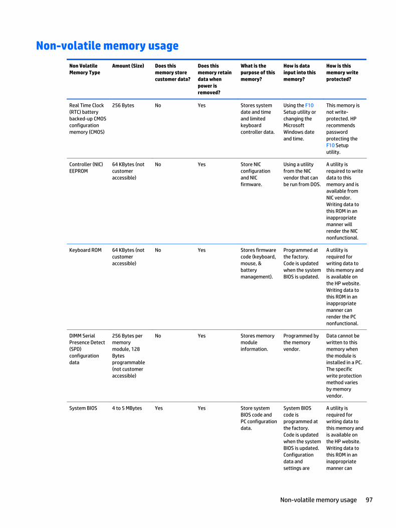
Non-volatile memory usage
Non Volatile Memory Type
Amount (Size) Does this memory store customer data?
Does this memory retain data when power is removed?
What is the purpose of this memory?
How is data input into this memory?
How is this memory write protected?
Real Time Clock (RTC) battery backed-up CMOS configuration memory (CMOS)
256 Bytes No Yes Stores system date and time and limited keyboard controller data.
Using the F10 Setup utility or changing the Microsoft Windows date and time.
This memory is not write-protected. HP recommends password protecting the F10 Setup utility.
Controller (NIC) EEPROM
64 KBytes (not customer accessible)
No Yes Store NIC configuration and NIC firmware.
Using a utility from the NIC vendor that can be run from DOS.
A utility is required to write data to this memory and is available from NIC vendor. Writing data to this ROM in an inappropriate manner will render the NIC nonfunctional.
Keyboard ROM 64 KBytes (not customer accessible)
No Yes Stores firmware code (keyboard, mouse, & battery management).
Programmed at the factory. Code is updated when the system BIOS is updated.
A utility is required for writing data to this memory and is available on the HP website. Writing data to this ROM in an inappropriate manner can render the PC nonfunctional.
DIMM Serial Presence Detect (SPD) configuration data
256 Bytes per memory module, 128 Bytes programmable (not customer accessible)
No Yes Stores memory module information.
Programmed by the memory vendor.
Data cannot be written to this memory when the module is installed in a PC. The specific write protection method varies by memory vendor.
System BIOS 4 to 5 MBytes Yes Yes Store system BIOS code and PC configuration data.
System BIOS code is programmed at the factory. Code is updated when the system BIOS is updated. Configuration data and settings are
A utility is required for writing data to this memory and is available on the HP website. Writing data to this ROM in an inappropriate manner can
Non-volatile memory usage 97

Non Volatile Memory Type
Amount (Size) Does this memory store customer data?
Does this memory retain data when power is removed?
What is the purpose of this memory?
How is data input into this memory?
How is this memory write protected?
input using the F10 setup utility or a custom utility.
render the PC nonfunctional.
Intel Management Engine Firmware (present only in models ending in a ‘p’ or ‘w’ or with Intel Centrino Pro technology)
1.5 or 5 MBytes Yes Yes Stores Management Engine Code, Settings, Provisioning Data and iAMT third party data store.
Management Engine Code is programmed at the factory. Code is updated via Intel secure firmware update utility. Unique Provisioning Data can be entered at the factory or by an administrator using the Management Engine (MEBx) setup utility. The third party data store contents can populated by a remote management console or local applications registered by an administrator to have access to the space.
The Intel chipset is configured to enforce hardware protection to block all direct read/write access to this area. An Intel utility is required for updating the firmware. Only firmware updates digitally signed by Intel can be applied using this utility.
Bluetooth flash 2 MBits No Yes Stores Bluetooth configuration and firmware.
Programmed at the factory. Tools for writing data to this memory are not publicly available but can be obtained from the silicon vendor.
A utility is required for writing data to this memory and is made available through newer versions of the driver if the flash requires an upgrade.
802.11 WLAN EEPROM
4 KBytes to 8 KBytes
No Yes Stores configuration and calibration data.
Programmed at the factory. Tools for writing data to this memory are not made public.
A utility is required for writing data to this memory and is typically not made available to the public unless a firmware upgrade is necessary to address a unique issue.
98 Chapter 15 Statement of Volatility

Non Volatile Memory Type
Amount (Size) Does this memory store customer data?
Does this memory retain data when power is removed?
What is the purpose of this memory?
How is data input into this memory?
How is this memory write protected?
Webcamera 64 KBits No Yes Store webcamera configuration and firmware.
Using a utility from the device manufacturer that can be run from Windows.
A utility is required for writing data to this memory and is typically not made available to the public unless a firmware upgrade is necessary to address a unique issue.
Fingerprint reader
512 KBytes flash Yes Yes Stores fingerprint templates.
By enrolling in HP ProtectTools Security Manager.
Only a digitally signed application can make the call to write to the flash.
Questions and answers1. How can the BIOS settings be restored (returned to default settings)?
a. Turn on or restart the computer and press F10 when prompted near the bottom of the display.
b. Select File, then select Restore defaults.
c. Follow the on-screen instructions.
d. Select File, save changes and exit, then press Enter.
2. What kind of configuration data is stored on the DIMM Serial Presence Detect (SPD) memory module? How would this data be written?
The DIMM SPD memory contains information about the memory module such as size, serial number, data width, speed/timing, voltage and thermal information. This information is written by the module manufacturer and stored on an EEPROM. This EEPROM cannot be written to when the memory module is installed in a PC. Third party tools do exist that can write to the EEPROM when the memory module is not installed in a PC. There are various third party tools available to read SPD memory.
3. Does the “Firmware Hub for System BIOS” contain the BIOS program? Is this chip writable, and if so how?
The Firmware Hub does contain the BIOS program and is writable. A utility is required to perform the write function.
4. In some PC systems, the Firmware Hub for System BIOS is a flash memory chip so that updates can be written by the customer. Is this true for these BIOS chips?
Yes, they are flash memory chips.
Questions and answers 99

5. What is meant by “Restore the nonvolatile memory found in Intel-based system boards?”
This relates to clearing the Real Time Clock (RTC) CMOS memory that contains PC configuration data.
6. Does resetting the CMOS configuration memory return the PC back to factory defaults?
The process of resetting the CMOS will return certain system settings to factory default but will not reset many of the system data and configuration defaults to their default settings. To return these system data and configuration defaults to default settings, refer to question and answer 1 and follow the instructions for returning the BIOS settings to factory defaults.
100 Chapter 15 Statement of Volatility

16 Power cord set requirements
The wide-range input feature of the computer permits it to operate from any line voltage from 100 to 120 volts AC, or from 220 to 240 volts AC.
The 3-conductor power cord set included with the computer meets the requirements for use in the country or region where the equipment is purchased.
Power cord sets for use in other countries and regions must meet the requirements of the country or region where the computer is used.
Requirements for all countriesThe following requirements are applicable to all countries and regions:
● The length of the power cord set must be at least 1.0 m (3.2 ft) and no more than 1.8 m (6 ft).
● All power cord sets must be approved by an acceptable accredited agency responsible for evaluation in the country or region where the power cord set will be used.
● The power cord sets must have a minimum current capacity of 10 amps and a nominal voltage rating of 125 or 250 V AC, as required by the power system of each country or region.
● The appliance coupler must meet the mechanical configuration of an EN 60 320/IEC 320 Standard Sheet C13 connector for mating with the appliance inlet on the back of the computer.
Requirements for specific countries and regions
Country/region Accredited agency Applicable note number
Australia EANSW 1
Austria OVE 1
Belgium CEBC 1
Canada CSA 2
Denmark DEMKO 1
Finland FIMKO 1
France UTE 1
Germany VDE 1
Italy IMQ 1
Japan METI 3
The Netherlands KEMA 1
Norway NEMKO 1
The People's Republic of China COC 5
South Korea EK 4
Requirements for all countries 101
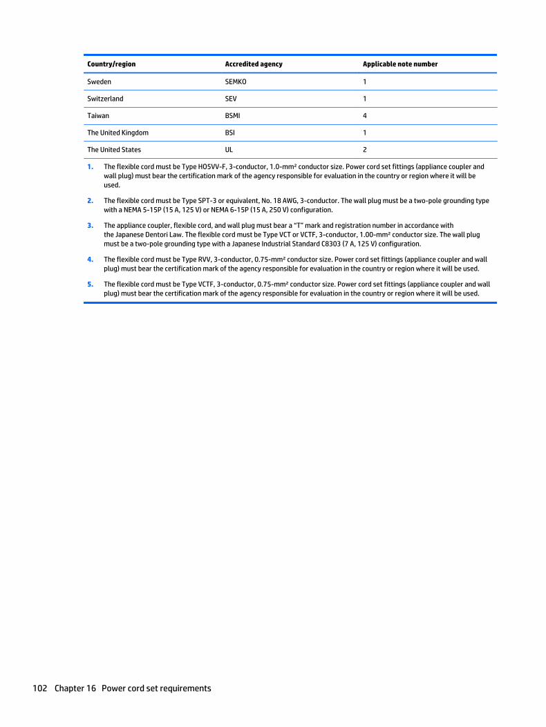
Country/region Accredited agency Applicable note number
Sweden SEMKO 1
Switzerland SEV 1
Taiwan BSMI 4
The United Kingdom BSI 1
The United States UL 2
1. The flexible cord must be Type HO5VV-F, 3-conductor, 1.0-mm² conductor size. Power cord set fittings (appliance coupler and wall plug) must bear the certification mark of the agency responsible for evaluation in the country or region where it will be used.
2. The flexible cord must be Type SPT-3 or equivalent, No. 18 AWG, 3-conductor. The wall plug must be a two-pole grounding type with a NEMA 5-15P (15 A, 125 V) or NEMA 6-15P (15 A, 250 V) configuration.
3. The appliance coupler, flexible cord, and wall plug must bear a “T” mark and registration number in accordance with the Japanese Dentori Law. The flexible cord must be Type VCT or VCTF, 3-conductor, 1.00-mm² conductor size. The wall plug must be a two-pole grounding type with a Japanese Industrial Standard C8303 (7 A, 125 V) configuration.
4. The flexible cord must be Type RVV, 3-conductor, 0.75-mm² conductor size. Power cord set fittings (appliance coupler and wall plug) must bear the certification mark of the agency responsible for evaluation in the country or region where it will be used.
5. The flexible cord must be Type VCTF, 3-conductor, 0.75-mm² conductor size. Power cord set fittings (appliance coupler and wall plug) must bear the certification mark of the agency responsible for evaluation in the country or region where it will be used.
102 Chapter 16 Power cord set requirements

17 Recycling
When a non-rechargeable or rechargeable battery has reached the end of its useful life, do not dispose of the battery in general household waste. Follow the local laws and regulations in your area for battery disposal.
HP encourages customers to recycle used electronic hardware, HP original print cartridges, and rechargeable batteries. For more information about recycling programs, see the HP Web site at http://www.hp.com/recycle.
103

Index
AAC adapter light 15AC adapter, spare part numbers 22ambient light sensor 8antenna, location 8audio, product description 1, 2audio-in jack 13audio-out jack 13
BBackup and Restore 92backup tools 90backups
creating 91recovering 92
batteryremoval 29spare part number 22, 29
battery bay 16battery bay cover release latch 16BIOS
determining version 67, 74downloading an update 67, 74updating 67, 74
bottom components 16bottom cover
removal 44spare part number 21, 44
buttonspower 13rotation lock 13TouchPad 12TouchPad on/off 12volume 13Windows 10Windows Home 8
Ccaps lock light 11chipset, product description 1components
bottom 16display 8keys 10left-side 12
lights 11rear 15right-side 13TouchPad 12
computermajor components 18
Computer Setupnavigating and selecting 65, 72restoring factory settings 66, 73
Ddisplay assembly
removal 56spare part number 19, 56
display components 8display panel, product description 1DisplayPort 15docking port 14docking, product description 3Driver Recovery DVD,
creating 90using for restore 93
Eesc key 10Ethernet, product description 2
Ff11 recovery 87, 93fan/heat sink assembly
removal 53spare part number 21, 53
fn key 10function keys 10
Ggraphics, product description 1
Hhard drive recovery 87, 93headphone jack 13hinge cover
removal 55spare part number 19, 55
HP PC Hardware Diagnostics (UEFI)downloading 70using 70
HP Recovery Disc Creator, using 90HP Recovery partition
checking for presence 93using for recovery 93
Jjacks
audio-in 13audio-out 13headphone 13microphone 13network 15RJ-45 (network) 15
Kkey components 10keyboard
product description 3removal 41spare part numbers 19, 41
keysesc 10fn 10function 10Windows application 10
Lleft-side components 12legacy support, USB 65, 72light components 11lights
AC adapter 15caps lock 11microphone mute 11mute 11num lock 11power 13TouchPad 11webcam 8wireless 11
104 Index

Mmemory card bezel, removal 30Memory Card Reader, location 13memory module
product description 1removal 38spare part numbers 21, 38
microphonelocation 8product description 1, 2
microphone jack 13microphone mute light 11miscellaneous part 22model name 1mute light 11
Nnetwork jack 15NFC antenna 16NFC board
removal 40spare part number 21, 40
num lock light 11numeric keypad 10
Ooperating system, product
description 3, 4, 5
PPlastics/Rubber Kit, spare part
number 22pointing device, product
description 3ports
DisplayPort 15docking 14product description 2USB 3.0 15
power button 13power button board
removal 48spare part number 21, 48
power connector 15power cord
set requirements 101spare part numbers 22, 23
power light 13power requirements, product
description 3processor, product description 1
product descriptionaudio 1, 2chipset 1display panel 1docking 3Ethernet 2external media cards 2graphics 1keyboard 3memory module 1microphone 1, 2operating system 3, 4, 5pointing device 3ports 2power requirements 3processors 1product name 1security 3sensors 2, 3serviceability 5solid-state drive 1video 1, 2wireless 2
product name 1
Rrear components 15recovery 89recovery media
creating 90using for restore 93
recovery partition 87, 93recovery tools 90recovery tools, Windows 92recovery, system 92refresh 89removal/replacement
procedures 29, 39reset 89restoring the hard drive 87, 93right-side components 13RJ-45 (network) jack 15rotation lock button 13RTC battery
removal 49spare part number 21, 49
rubber screw cover, removal 30
SScrew Kit, spare part number 23
security cable slot, location 15security, product description 3sensors, product description 2, 3service cover
location 16removal 30spare part numbers 22, 30
service tag 17serviceability, product description 5setup utility
navigating and selecting 65, 72restoring factory settings 66, 73
solid-state driveproduct description 1removal 36spare part numbers 21, 36
Speaker Kit, spare part number 21, 47
speakerslocation 12, 13removal 47spare part number 21, 47
specifications 79Startup Repair, using 92Sure Start 71system board
removal 50spare part numbers 20, 50
Ttop cover, spare part number 20TouchPad button 12TouchPad components 12TouchPad light 11TouchPad on/off button 12TouchPad zone 12
UUSB 3.0 port 15USB legacy support 65, 72
Vvent 12, 16video, product description 1, 2volume button 13
Wwebcam 8webcam light 8
Index 105

WindowsRefresh 89Reset 89
Windows 7 operating system DVDcreating 90using for restore 93
Windows 7 operating system mediacreating 90using for restore 93
Windows application key 10Windows button 10Windows Home button 8Windows operating system DVD 88Windows Startup Repair, using 92wireless antenna, location 8wireless light 11wireless, product description 2WLAN module
removal 34spare part numbers 22, 34
WWAN moduleremoval 32spare part numbers 21, 32
106 Index