hp capture and route (hp cr) installation...
TRANSCRIPT

HP Capture and Route (HP CR)Installation Guide

ii
HP Capture and Route (HP CR)
Installation Guide
Edition: March 2013

iii
Legal notices
(c) Copyright 2013 Hewlett-Packard Development Company, L.P.
Confidential computer software. Valid license from HEWLETT-PACKARD required for possession, use or copying. Consistent with FAR 12.211 and 12.212, Commercial Computer Software, Computer Software Documentation, and Technical Data for Commercial Items are licensed to the U.S. Government under vendor's standard commercial license.
The information contained herein is subject to change without notice. The only warranties for HEWLETT-PACKARD products and services are set forth in the express warranty statements accompanying such products and services. Nothing herein should be construed as constituting an additional warranty. HEWLETT-PACKARD shall not be liable for technical or editorial errors or omissions contained herein.
Microsoft, Windows, and Windows NT are U.S. registered trademarks of Microsoft Corporation.
Printed in the US

iv
Revision history
Table 1 Revisions
Date Edition Revision
April 2012 1 Version 1.1
September 2012 2 Version 1.2.0
March 2013 3 Version 1.2.0

v
Contents
Part I: Server
1 Introduction1-1 HP Capture and Route overview.................................................................................................................. 3
1-1-1 Scalability and automated failover ...................................................................................................... 31-2 Built-in HP CR server features ..................................................................................................................... 41-3 Clients and specialized integrations ............................................................................................................. 41-4 Localized clients and device buttons............................................................................................................ 51-5 Server deployment summary ....................................................................................................................... 51-6 On-line help and related documentation ...................................................................................................... 6
2 Requirements2-1 Hardware and software requirements .......................................................................................................... 7
2-1-1 Supported devices .............................................................................................................................. 82-1-2 Additional installation requirements .................................................................................................... 92-1-3 Additional software considerations for a composer .......................................................................... 10
2-2 Creating the HP CR service account.......................................................................................................... 102-3 Creating the HP CR Admins group ............................................................................................................ 112-4 Configuring Distributed COM (DCOM) permissions................................................................................... 11
2-4-1 Configuring DCOM permissions on Windows 2008 and Windows 2003 .......................................... 112-5 Setting up Microsoft SMTP service ............................................................................................................ 12
2-5-1 Setting up SMTP server for IIS 7.0 ................................................................................................... 122-5-2 Setting up SMTP server for IIS 6.0 ................................................................................................... 13
2-6 Configuring Internet Information Services (IIS) .......................................................................................... 132-6-1 Configuring IIS when installing the HP CR server on Windows 2008 systems ................................ 132-6-2 Configuring IIS to run 32-bit applications.......................................................................................... 14
2-7 Enabling and configuring integrated Windows authentication.................................................................... 142-7-1 Enabling integrated Windows authentication.................................................................................... 142-7-2 Configuring integrated Windows authentication on the web server.................................................. 14
2-8 Installing a Microsoft SQL application on the HP CR server ...................................................................... 152-8-1 Installing SQL Server 2008 SP2....................................................................................................... 152-8-2 Installing SQL Express 2008 ............................................................................................................ 15
2-9 Disabling the Internet Explorer enhanced security configuration component ............................................ 242-10 Enabling 8.3 name creation on NTFS partitions....................................................................................... 25
3 Installing the HP CR server3-1 Installing the HP CR server ........................................................................................................................ 273-2 Completing the server configuration wizard ............................................................................................... 31
3-2-1 Note about the registry keys location for HP CR server ................................................................... 32
4 HP CR post installation review and configurations4-1 Modifying the HP CR Server Administrator ................................................................................................ 33
4-1-1 Activating the server license ............................................................................................................. 334-1-2 Specifying the originator of notification messages............................................................................ 354-1-3 How the routing rules work after installation ..................................................................................... 364-1-4 Configuring group permissions ......................................................................................................... 374-1-5 Adding and configuring network printers for groups ......................................................................... 374-1-6 Adding and configuring network folders for groups .......................................................................... 394-1-7 FTP and FTPS support requirements............................................................................................... 45

vi
Contents
4-1-8 Managing the Web Client views ....................................................................................................... 554-1-9 Managing devices............................................................................................................................. 55
4-2 Modifying components ............................................................................................................................... 564-2-1 Billing component ............................................................................................................................. 564-2-2 Compose component........................................................................................................................ 574-2-3 Data Extractor component ................................................................................................................ 604-2-4 Dispatch component ......................................................................................................................... 604-2-5 Embedded Directive Manager component ....................................................................................... 604-2-6 Lookup Manager component ............................................................................................................ 614-2-7 Maintenance component .................................................................................................................. 624-2-8 Notification component ..................................................................................................................... 634-2-9 Preview Manager component ........................................................................................................... 63
4-3 Modifying connectors ................................................................................................................................. 644-3-1 Database connector.......................................................................................................................... 654-3-2 Document Management System (DMS) connectors ........................................................................ 654-3-3 Fax connector options ...................................................................................................................... 674-3-4 Filescan connector............................................................................................................................ 684-3-5 HP CR Server connector .................................................................................................................. 694-3-6 Printer connector .............................................................................................................................. 694-3-7 SMTP connector ............................................................................................................................... 704-3-8 XMLScan connector ......................................................................................................................... 71
4-4 Implementing and configuring the HP CR Intelligent Device Client ........................................................... 714-4-1 HP CR Intelligent Device Client components ................................................................................... 714-4-2 Optional configuration: Modifying the directory security configuration of virtual directories ............. 724-4-3 Testing connectivity to the Intelligent Device Client.......................................................................... 73
Part II: Remote Components
5 Installing a Remote Administrator5-1 Requirements for the Remote Administrator .............................................................................................. 775-2 Installing the Remote Administrator ........................................................................................................... 785-3 Starting the HP CR Server Administrator and connecting to the HP CR Server........................................ 805-4 Problems connecting to the HP CR server using Remote Administrator ................................................... 80
6 Installing a remote Composer6-1 Requirements for a remote Composer ....................................................................................................... 82
6-1-1 Basic requirements ........................................................................................................................... 826-1-2 Software requirements for message conversion .............................................................................. 82
6-2 Installing the remote Composer ................................................................................................................. 836-3 Adding the Composer to the HP CR server ............................................................................................... 85
7 Installing a remote modem server7-1 Requirements for a remote modem server................................................................................................. 887-2 Installing and testing Brooktrout system software ...................................................................................... 887-3 Installing the remote modem server ........................................................................................................... 897-4 Detecting channels on the modem server.................................................................................................. 917-5 Configuring a path to the Telco share directory ......................................................................................... 92
8 Installing the remote HP CR Intelligent Device Client8-1 Requirements for the HP CR Intelligent Device Client ............................................................................... 95
8-1-1 Basic requirements ........................................................................................................................... 958-1-2 HTTP and HTTPs requirements ....................................................................................................... 958-1-3 Required COM permissions for the remote HP CR Intelligent Device Client ................................... 96
8-2 Installing the remote HP CR Intelligent Device Client ................................................................................ 96

Contents
vii
8-3 Configuring the remote Intelligent Device Client ........................................................................................ 988-3-1 Specifying the HP CR Server ........................................................................................................... 988-3-2 Adding the application pool logon account to the HP CR Admins group.......................................... 998-3-3 Other configurations ....................................................................................................................... 100
9 HP CR Embedded Device Client for HP OXPd
10 HP CR End User Interface10-1 HP CR End User Interface requirements ............................................................................................... 104
10-1-1 Basic requirements ....................................................................................................................... 10410-1-2 User requirements: email account ................................................................................................ 10510-1-3 User requirements: full permissions ............................................................................................. 105
10-2 Installing the HP CR End User Interface ................................................................................................ 10610-2-1 Installing the End User Interface................................................................................................... 10610-2-2 Required DCOM permissions when installing on a remote system.............................................. 108
10-3 Required configuration ........................................................................................................................... 10810-3-1 Enabling integrated Windows authentication................................................................................ 10810-3-2 Adding the End User Interface URL to the list of trusted sites on a client system........................ 10910-3-3 Selecting a network printer ........................................................................................................... 10910-3-4 Configuring required COM permissions for launching the remote End User Interface................. 11010-3-5 Configuring required firewall settings for launching a remote End User Interface........................ 111
10-4 Optional configuration - Customizing the HP CR End User Interface .................................................... 11210-4-1 Using the Administrator Web Client Views Management tool to set up primary customized options ..................................................................................................................... 11210-4-2 Modifying the View.default.xml file for secondary customized options ......................................... 118
10-5 Optional configuration - Configuring the HP CR Server Administrator................................................... 11910-5-1 Adding the HP CR End User Interface URL to the HP CR Server Administrator ......................... 11910-5-2 Configuring prompts ..................................................................................................................... 12010-5-3 Configuring additional custom options.......................................................................................... 120
11 HP CR for Microsoft SharePoint11-1 Microsoft SharePoint requirements ........................................................................................................ 12111-2 Installing HP CR for SharePoint client on the Microsoft SharePoint server ........................................... 12111-3 Configuration .......................................................................................................................................... 122
11-3-1 Disabling the pop-up blocker in Internet Explorer......................................................................... 12211-3-2 Configuring the HP CR connector for Microsoft SharePoint......................................................... 12211-3-3 Setting anonymous authentication for UploadFile.aspx................................................................ 12211-3-4 Configuring full control permissions for members of the group .................................................... 12211-3-5 Setting PDF documents to append date/time stamp for unique file name.................................... 123
12 HP CR for Autonomy WorkSite12-1 Autonomy iManage WorkSite requirements........................................................................................... 12512-2 Installing HP CR for Autonomy WorkSite client on the DeskSite or FileSite client system .................... 12512-3 Setting up end user extensions .............................................................................................................. 126
13 HP CR Server Monitor13-1 Requirements ......................................................................................................................................... 129
13-1-1 HP CR Server Monitor service requirements................................................................................ 12913-1-2 HP CR Server Monitor Administrator requirements...................................................................... 13013-1-3 Additional installation requirements .............................................................................................. 130
13-2 Installing HP CR Server Monitor ............................................................................................................ 13013-3 Required configuration ........................................................................................................................... 131
13-3-1 Configuring HP CR connectors for Filescan and Telco ................................................................ 13113-3-2 Configuring HP CR server properties ........................................................................................... 13413-3-3 Clustering...................................................................................................................................... 13413-3-4 Defining sender and recipient email addresses............................................................................ 135

viii
Contents
13-3-5 Defining server properties: The General tab................................................................................. 13513-3-6 Optional configuration................................................................................................................... 136
Part III: Additional Information
14 Setting up an HP CR server cluster14-1 Introduction to failover ............................................................................................................................ 13914-2 Requirements for an HP CR server cluster ............................................................................................ 141
14-2-1 HP CR server requirements.......................................................................................................... 14114-2-2 Database server requirements ..................................................................................................... 14114-2-3 Remote device server requirements............................................................................................. 141
14-3 Setting up the database server .............................................................................................................. 14214-3-1 Creating folders for HP CR server resources stored on the database server .............................. 14214-3-2 Creating the Telco share .............................................................................................................. 142
14-4 Setting up the active server.................................................................................................................... 14214-4-1 Installing the HP CR server .......................................................................................................... 14214-4-2 Configuring the HP CR connector for Telco to use the Telco share on the database server ....... 14214-4-3 Moving HP CR server resources and redefining logicals ............................................................. 143
14-5 Setting up the passive server ................................................................................................................. 14414-6 Adding and activating the failover server license ................................................................................... 14514-7 Enabling failover by setting up an HP CR server cluster........................................................................ 14514-8 Testing the failover configuration by simulating a localized system failure on the active server............ 14614-9 Optional configurations for cluster environments ................................................................................... 147
14-9-1 Setting up the remote device server ............................................................................................. 14714-9-2 Configuring the HP CR Web Client for failover............................................................................. 14714-9-3 Clustering and Composer thread awareness ............................................................................... 147
14-10 Disabling SMB2 on a Windows 2008 R2 HP CR server cluster........................................................... 148
15 Installing and configuring a Dialogic modem driver15-1 Requirements for installing and configuring the SR140 module ............................................................ 149
15-1-1 HP CR software requirements ...................................................................................................... 14915-1-2 Driver requirement ........................................................................................................................ 14915-1-3 Gateway requirement ................................................................................................................... 14915-1-4 Additional Requirements............................................................................................................... 149
15-2 Installing the BrookTrout SR140 module................................................................................................ 14915-2-1 Installing Brooktrout v6.4.0 drivers ............................................................................................... 14915-2-2 Installing 6.4.0_x64.msi ................................................................................................................ 15015-2-3 Activating the license.................................................................................................................... 15015-2-4 Applying the license...................................................................................................................... 152
15-3 Configuring Brooktrout SR140 ............................................................................................................... 15215-3-1 Additional SIP configuration.......................................................................................................... 15315-3-2 Additional H.323 configuration...................................................................................................... 15315-3-3 Setting the maximum page size.................................................................................................... 154
15-4 Testing.................................................................................................................................................... 154
Part IV: Software Technology Integrations
16 Software Integrations16-1 Multi-vendor device configuration........................................................................................................... 157
16-1-1 Ricoh............................................................................................................................................. 15716-1-2 Sharp: Address registration with the Sharp MX-C311.................................................................. 15716-1-3 Xerox: Creating a new workflow template with the Xerox WorkCentre 6400 ............................... 160
16-2 HP Access Control ................................................................................................................................. 161

ix
Contents
16-3 HP Autonomy TeleForm......................................................................................................................... 16216-3-1 Configuring the HP CR server ...................................................................................................... 16216-3-2 Enabling HP CR XMLStore........................................................................................................... 16316-3-3 Enabling HP CR XMLScan........................................................................................................... 175
Part V: Appendices
A Upgrading HP CR v1.1 to HP CR v1.2.0 ....................................................................................................... 179A-1 Backing up the database ........................................................................................................................ 179A-2 Cancelling messages in the In Process queue 1 ....................................................................................... 80A-3 Backing up the templates ........................................................................................................................ 180A-4 Uninstalling clients .................................................................................................................................. 180A-5 Uninstalling device clients from HP CR Server Administrator ................................................................. 181A-6 Deleting device clients and the Default group from the HP CR Server Administrator ............................ 181A-7 Uninstalling HP CR v1.1 clients from Programs and Features ............................................................... 181A-8 Running the server installation on the HP CR v1.1 system .................................................................... 182A-9 Installing clients ....................................................................................................................................... 183
B Installing HP CR in a Non-English Environment ............................................................................................ 185B-1 Setting up a server before installing HP CR ........................................................................................... 185B-2 Installing HP CR ...................................................................................................................................... 185B-3 Troubleshooting ...................................................................................................................................... 186

x
Figures and Tables
FiguresFigure 4-1 The HP CR Intelligent Device Client environment ............................................................................. 71Figure 4-2 Default Authentication and Access Control Configuration for a Virtual Directory .............................. 72Figure 5-1 HP CR server with HP CR Server Administrator and Remote Administrators .................................. 77Figure 5-2 HP CR server with a local Composer and remote Composers ......................................................... 81Figure 6-1 Server with a local modem server and remote modem servers ........................................................ 87Figure 10-1 End User Interface .......................................................................................................................... 104Figure 13-1 HP CR Server Monitor Properties ................................................................................................... 134Figure 13-2 Default Test Criteria screen ............................................................................................................. 135Figure 14-1 HP CR server cluster basic setup ................................................................................................... 140Figure 14-2 HP CR server cluster in failover mode ............................................................................................ 140
TablesTable 1 Revisions ............................................................................................................................................. 4Table 2 Description of Intelligent Device Client components with location and function ................................ 56Table 3 HP CR scanning features in Embedded Device Client for HP OXPd ................................................ 82Table 4 Description of installation components with locations and functions ................................................. 84Table 5 List of devices supported with Embedded Device Client for HP OXPd ............................................. 87

Part I:
Server


3
1 Introduction
The HP Capture and Route Installation Guide contains instructions on installing and configuring HP Capture and Route (HP CR), an enterprise application. The Guide is written for system administrators who have detailed knowledge of the Windows operating system and LANs.
This section describes:
HP Capture and Route overview (3)
Built-in HP CR server features (4)
Clients and specialized integrations (4)
Server deployment summary (5)
On-line help and related documentation (6)
1-1 HP Capture and Route overviewHP Capture and Route (HP CR) is a server-based software application for document capture, which operates on a Microsoft Windows server within a customer’s network. Users can access HP CR’s document capture and routing capabilities from any scan-enabled MFP or network-connected scanner. HP CR converts captured documents into a variety of image- and text-based document formats and delivers them to a wide range of destinations.
Documents are transferred from a web-based End User Interface, MFP, or network scanner to the HP CR server, which processes and delivers them to specified destinations. If the device used to scan a document is an HP device enabled with the HP OXPd embedded platform, and the capture function or document process requires it, the user may be prompted at the time of scanning to enter indexing meta-data or recipient addressing information. Certain document processes may also specify that a user receive notification upon final job delivery through the system. Notification messages can be sent to the scanning user’s email address or as a confirmation page printed back to the source scan device if that device is an MFP and capable of printing these confirmations.
1-1-1 Scalability and automated failoverHP CR is a highly scalable enterprise application that can be deployed in organizations of all sizes. Its robust server-client architecture supports distributed workloads, versatile throughput, and unmatched document distribution capabilities using numerous delivery systems and methods.
With smaller workloads, the HP CR server can suitably perform all the functions required for document distribution. As an organization grows, the server workload can be distributed or completely off-loaded using one or all of the following components:
Remote Administrator - A remote system hosting HP CR Server Administrator, which is the HP CR server management application. (See Section 5: Installing a Remote Administrator, 77.)
Remote Compose (Composer) - A remote system hosting a Composer, which performs document conversion tasks. (See Section 6: Installing a remote Composer, 81.)
Remote Modem Server - A remote system hosting a modem server. (See Section 7: Installing a remote modem server, 87.)
Remote Intelligent Device Client - A remote system hosting an HP CR Intelligent Device Client. (See Section 8: Installing the remote HP CR Intelligent Device Client, 95.)

4
Introduction
Secondary Server - A secondary system in a failover configuration. (See Section 14: Setting up an HP CR server cluster, 139.)
In addition to scalability, the HP CR supports automated failover. In case of a system failure on the HP CR server, automated failover promises seamless recovery using a standby server.
1-2 Built-in HP CR server featuresThe HP CR server includes these built-in features:
Centralized administration - You can manage an HP CR server using the HP CR Server Administrator, a snap-in for Microsoft Management Console. After connecting the HP CR Server Administrator to your HP CR server in the LAN, you can:
Modify the configuration of server components
Manage the server connectors
Manage user permissions and feature access
Monitor message processing
Manipulate rules for handling inbound and outbound messages
Troubleshoot errors
Automated self-maintenance - You can manage the HP CR server databases using the Maintenance component. You can configure the Maintenance component Cleanup feature to remove messages and archive entries from the database after a specified length of time. You can also configure the Archive feature to copy messages to an archive database and remove the messages from the archive after a specified length of time.
Customized document workflow - You can create rules to determine how the HP CR server will process inbound and outbound messages. The rules are highly configurable and can be manipulated to achieve specific results.
Configurable user permissions and feature access - You can create Groups and configure user permissions in the HP CR Server Administrator. The collection of group records determines the access privilege of each user to the HP CR End User Interface and Preview. (Preview is a configurable feature that makes a user’s messages available for preview before they are sent.) The user default configuration applies globally to users who do not require special permissions or feature access.
1-3 Clients and specialized integrationsHP CR features are accessible where the users need them most—on the web, office machines, multifunction devices, and business systems that are an integral part of the communication workflow.
HP CR is an intranet-based application for:
Multifunction devices and business systems - Supports software solutions complementing the hardware solutions offered by Hewlett Packard as well as integrating with other vendor devices such as Ricoh Corporation, Sharp Electronics Corporation, and Xerox Corporation.
NOTE: HP CR server does not support HP Chai Device Client. If you are using Chai and are upgrading to HP CR, install the Embedded Device Client for HP OXPd v1.4 available on the server clients directory. For download, installation, and configuration instructions, refer to the HP Capture and Route (HP CR) Embedded Device Client for HP OXPd Installation Guide.

Introduction
5
NOTE: When scanning from Ricoh devices, users must choose Multi-paged PDF in the scan options of the device.
Document and records management systems - HP CR integrates with document and records management solutions including Microsoft® SharePoint®, Autonomy iManage WorkSite, and FileShare.
Refer to Section 16: Software Integrations (157) and the HP Capture and Route (HP CR) Embedded Device Client for HP OXPd Installation Guide for more information.
1-4 Localized clients and device buttonsHP CR, device clients, and standard device buttons have been localized for Simplified Chinese, French, German, Italian, Brazilian Portuguese, and Spanish. Localization includes:
HP CR End User Interface and the HP Capture and Route (HP CR) User Guide.
HP CR for HP OXPd v1.6 Device Client and the associated Quick Start Guide.
HP CR for HP OXPd v1.4 Device Client and the associated Quick Start Guide.
HP CR for Microsoft SharePoint and the associated Quick Start Guide.
HP CR for Autonomy WorkSite and the associated Quick Start Guide.
Standard device buttons have been localized. Note, however, that the Administrator can modify the text as it appears on a device button. These buttons will not appear as localized unless the Administrator enters the text in the applicable language.
1-5 Server deployment summaryTo deploy the HP CR server:
1. Complete the installation requirements using the guidelines provided in Section 2: Requirements (7).
2. Install the HP CR server using the instructions in Section 3: Installing the HP CR server (27).
3. Perform required configurations using the instructions in Section 4: HP CR post installation review and configurations (33).
4. Set up SMTP integration. Refer to the SMTP connector information in the HP CR administrator on-line help for instructions.
5. Set up other server-side related features such as:
Remote Administrator (Section 5: Installing a Remote Administrator, 77)
Remote Composer (Section 6: Installing a remote Composer, 81)
Remote Modem Server (Section 7: Installing a remote modem server, 87)
Remote HP CR Intelligent Device Client (Section 8: Installing the remote HP CR Intelligent Device Client, 95)
6. Set up the HP CR End User Interface where users can create Distribution Rules. Refer to Section 10: HP CR End User Interface (103). In addition, consult the HP CR User Guide, which has links to the HP CR End User Interface and all other related documentation for the HP CR server.

6
Introduction
1-6 On-line help and related documentationClick the Help button at any time to access HP CR on-line documentation.
Refer also to the HP Capture and Route v1.2.0 Release Notes.

7
2 Requirements
Before you can install the HP CR server on a system, you must configure the system. This section discusses hardware and software requirements for the HP CR server as well as required server configurations.
This section describes:
Hardware and software requirements (7)
Creating the HP CR service account (10)
Creating the HP CR Admins group (11)
Configuring Distributed COM (DCOM) permissions (11)
Setting up Microsoft SMTP service (12)
Configuring Internet Information Services (IIS) (13)
Enabling and configuring integrated Windows authentication (14)
Installing a Microsoft SQL application on the HP CR server (15)
Disabling the Internet Explorer enhanced security configuration component (24)
Enabling 8.3 name creation on NTFS partitions (25)
2-1 Hardware and software requirementsThe HP CR server installation requires a dedicated system that meets the following minimum requirements:
Dual core processor, 2 GHz, 4GB of RAM, RAID 5W with 100 GB of disk space, and Microsoft mouse or compatible pointing device
Windows 2008 R2 64-bit, 2003 Standard Edition SP2 64-bit
For Windows 2003 Standard Edition SP2 64-bit: Configure Internet Information Services (IIS) to run 32-bit applications (see Configuring IIS to run 32-bit applications (14) for instructions)
For Windows 2008 64-bit: Internet Information Services (IIS) v7 (see Configuring IIS when installing the HP CR server on Windows 2008 systems (13) for configuration instructions)
NOTE: For IIS v7 or later, configure to allow Active Server Pages. This configuration is located in the Web Service Extensions node in the IIS console tree.
Windows Active Directory - HP CR can only be installed in a Windows Active Directory environment. All server security and authentications are dependent on the Active Directory authentication.
Disabled Internet Explorer Enhanced Security Configuration (Windows component).
If this component is enabled, you cannot install HP CR server. After you disable the component, reboot your system before proceeding with the server installation. For instructions on how to verify that the component is disabled, see Disabling the Internet Explorer enhanced security configuration component (24).

8
Requirements
Microsoft .Net Framework 4.0, which is required to install the Embedded Device Client for HP OXPd, the Intelligent Device Client, and the End User Interface. The installation will install MS.net 4.0 if it is not found to be installed.
NOTE: Do not run any other enterprise application on the HP CR server.
Microsoft Internet Explorer 7 or later
Acrobat Reader 7.0 or later
Internet connection
2-1-1 Supported devicesHP CR supports the Embedded Device Client for HP OXPd on all devices listed below. Consult HP to determine compatible firmware versions for supported devices.
Table 1 List of devices supported with the Embedded Device Client for HP OXPd
Device Group Supported Firmware
Minimum Installed RAM
OXPd Version
Color LaserJet 4730 MFP 10 46.350.1 256 MB 1.4.9.0
Digital Sender 9200c 10 09.270.2 256 MB 1.4.9.0
LaserJet 4345 MFP 10 09.270.1 256 MB 1.4.9.0
LaserJet 9040 MFP 10 08.250.9 256 MB 1.4.9.0
LaserJet 9050 MFP 10 08.250.9 256 MB 1.4.9.0
LaserJet 9500 MFP 10 08.250.9 512 MB 1.4.9.0
Color LaserJet CM 4730 MFP 20 50.221.3 N/A 1.6.3.2
Digital Sender 9250c 20 48.171.2 N/A 1.6.3.2
LaserJet M3035 MFP 20 48.250.8 N/A 1.6.3.2
LaserJet M4345 MFP 20 48.250.8 N/A 1.6.3.2
LaserJet M4349 MFP 20 48.241.2 N/A 1.6.3.2
LaserJet M5035 MFP 20 48.241.2 N/A 1.6.3.2
LaserJet M5039 MFP 20 48.241.2 N/A 1.6.3.2
LaserJet M9040 MFP 20 51.191.3 N/A 1.6.3.2
LaserJet M9050 MFP 20 51.191.3 N/A 1.6.3.2
LaserJet M9059 MFP 20 51.191.3 N/A 1.6.3.2
Color LaserJet CM 6030 MFP 40 52.191.2 N/A 1.6.3.2
Color LaserJet CM 6040 MFP 40 52.200.4 N/A 1.6.3.2
Color LaserJet CM 6049 MFP 40 52.180.5 N/A 1.6.3.2
Color LaserJet CM 3530 MFP 50 53.180.3 N/A 1.6.3.2
Color LaserJet CM 4540 MFP XX 2200887_229562 N/A 1.6.3.2
ScanJet 7000n XX 2131311_192131 N/A 1.6.3.2

Requirements
9
2-1-2 Additional installation requirementsAn HP CR server installation also requires the following:
HP CR service account. For instructions on how to create the HP CR service account, see Creating the HP CR service account (10).
Windows user account that belongs to the local Administrators group. For instructions on how to create this group, see Creating the HP CR Admins group (11).
Configured IIS for a Windows 2008 system. For instructions, see Configuring IIS when installing the HP CR server on Windows 2008 systems (13).
Installed MS SQL application. For instructions, see Installing a Microsoft SQL application on the HP CR server (15).
(Optional) Installed, configured, and tested fax module for an HP CR server that supports faxing. Fax options are installed (or planned out) if faxing is going to be used in the HP CR environment. Faxing is available through the Telco, T37 SMTP, or HP Lanfax connector, depending on your environment. For information on modem installation, consult the fax connector options in the HP CR administrator on-line help.
Verified that the NtfsDisable8dot3NameCreation registry value is set to 0.
You must enable 8.3 Name Creation on NTFS Partitions to allow Ghostscript to work with long file names or with spaces and nonstandard characters in the file name during conversion. If your system does not have the registry key set to 0, you must manually enable the key and set the value to 0. For instructions, see Enabling 8.3 name creation on NTFS partitions (25).
Windows firewall settings: Turning off the firewall will allow exceptions for the mmc.exe and the DCOM port (135). If you do not want to turn off the Windows firewall, keep the firewall on and allow the DCOM port (135) and mmc.exe.
NOTE: If the firewall is on and you do not allow the DCOM port (135) and mmc.exe, you will get the following message when you try to open the HP CR Server Administrator after installing the server: 0x800706ba) The RPC server is unavailable.
ScanJet 8500 XX 2200643_228340 N/A 1.6.3.2
LaserJet Flow M525 MXP XX 2200893_229650 N/A 1.6.3.2a
LaserJet Flow M575 MXP XX 2200893_229649 N/A 1.6.3.2
LaserJet M775 MFP XX 2200890_229591 1.6.3.2
LaserJet M4555 MFP XX 2200887_229566 1.6.3.2
Device Group Supported Firmware
Minimum Installed RAM
OXPd Version

10
Requirements
2-1-3 Additional software considerations for a composerThe HP CR server setup automatically installs a local Composer on the server. This is needed to compose documents into the specified final formats.
A remote Composer is available (see Section 6: Installing a remote Composer (81) for details). The local and remote Composer must have the following applications and, optionally, Microsoft Word. For example, if you are planning to use Crystal Reports for composing, then Crystal Reports must be installed on the compose server.
Microsoft Visio 2007 for *.VSD and *.VDX message attachments (required)
Crystal Reports v10.0 or earlier for *.RPT message attachments (required)
Microsoft Office 2007 for *.DOC, *.DOCX, *.PPT, *.PPTX, *.XLS, and *.XLSX message attachments (recommended, but not required)
Microsoft Word 2007 for *.DOC Routing Sheet templates
IMPORTANT: After you install Microsoft Word, you must open a Word document and register the software. You must also verify that pop-ups do not appear to ensure successful composition of messages in the HP CR server.
NOTE: Routing Sheet templates are provided in *.DOC and *.OMTPL format. These templates can be edited in Word and WordPad, respectively.
If multiple versions of an application are deployed in the LAN, the most recent version must be installed on the Composer. For example, if Office 2007 and 2003 are deployed, then Office 2007 must be installed on the Composer.
An item is required only if the Composer must be able to convert the documents associated with the application. For example, if Microsoft Office is not deployed in the LAN, Microsoft Office does not need to be installed.
2-2 Creating the HP CR service accountThe HP CR service account is a dedicated Windows user account designed to run services on the HP CR server.
IMPORTANT: It is strongly recommended that you do not change this account or the password associated with it.
The HP CR service account user:
Must belong to the Domain Users group in the domain where the HP CR server is being installed.
Must belong to the local Administrators group on the system where the HP CR server is being installed.
Must have a password that never expires.
You can create or select a Windows user account as the HP CR service account. For instructions on creating Windows user accounts, consult Windows help.

Requirements
11
2-3 Creating the HP CR Admins groupThe Admins group consists of all HP CR users who run the HP CR Server Administrator (either on the HP CR Server or Remote Administrator). These users must have Distributed COM access, launch, and configuration permissions on the HP CR server.
To create an HP CR Admins group:
1. Go to the Active Directory or LDAP. Locate the domain where the HP CR server is being installed.
2. Create a group for HP CR Server Administrator users. Name this group HP CR Admins.
3. Add all users who will run the HP CR Server Administrator to the HP CR Admins group.
4. Log in to the system where the HP CR server is being installed using an account that belongs to the local Administrators group.
5. Add the HP CR Admins group to the local Administrators group.
When you need to add additional users to run the HP CR Server Administrator, you can add them to the HP CR Admins group.
2-4 Configuring Distributed COM (DCOM) permissions
The following users and groups require DCOM access, launch, and configuration permissions on the HP CR server:
HP CR service account user
HP CR Admins group
SYSTEM group on the HP CR server
INTERACTIVE group on the HP CR server
TIP: SYSTEM and INTERACTIVE are built-in accounts that are not visible in the list of local users and groups. SYSTEM is a group for Windows services that are configured to run in the local Windows security context. INTERACTIVE is a group to which the current local Windows user is automatically added.
2-4-1 Configuring DCOM permissions on Windows 2008 and Windows 2003
1. Log in to the system where you will install the HP CR server. Use the local Administrators group login credentials.
2. Run dcomcnfg. The Component Services console opens.
3. Go to the console root, expand Component Services.
4. Expand Computers. Go to the details pane, right-click My Computer, select Properties. The Properties page opens.
5. Go to COM Security.

12
Requirements
6. Configure access permissions:
a Go to the Access Permissions section.
b Click Edit Default. The Access Permission page opens.
c Verify that the HP CR service account user has Local Access and Remote Access permissions enabled. If necessary, add this group to the list.
d Verify that the HP CR Admins group has Local Access and Remote Access permissions enabled. If necessary, add this group to the list.
e Verify that INTERACTIVE and SYSTEM have Local Access and Remote Access permissions enabled. If necessary, add these groups to the list.
f Click OK.
7. Configure launch permissions:
a Go to Launch and Activation Permissions section.
b Click Edit Default. The Launch Permission page opens.
c Verify that the HP CR service account user has Local Launch, Remote Launch, Local Activation, and Remote Activation permissions enabled. If necessary, add this group to the list.
d Verify that the HP CR Admins group has Local Launch, Remote Launch, Local Activation, and Remote Activation permissions enabled. If necessary, add this group to the list.
e Verify that INTERACTIVE and SYSTEM have has Local Launch, Remote Launch, Local Activation, and Remote Activation permissions enabled. If necessary, add these groups to the list.
f Click OK.
8. Click Apply, OK, and right-click My Computer in Component Services.
9. Select Stop MS DTC, then select Start MSDTC.
10. Close Component Services.
2-5 Setting up Microsoft SMTP service
2-5-1 Setting up SMTP server for IIS 7.01. Click the Start button.
2. Click Administrator Tools > Server Manager.
3. Click the Features node in the Server Manager pane. Click Add Features in the Features Summary pane.
4. Click on the box next to SMTP Server, and the Add Features Wizard page opens clarifying which role services and features need to be installed.
5. Click the Add Required Role Services button. Click Next.
6. Click Next on the page that discusses the Web Server (IIS) role, which is already installed.
7. Review the installation selection on the next page and note that SMTP Server will be installed. Click Install.
8. Ensure that the installation is fully successfully, and then click Close.

Requirements
13
2-5-2 Setting up SMTP server for IIS 6.01. From the Start menu, click Control Panel.
2. Double-click Add or Remove Programs.
3. From the left pane, click Add/Remove Windows Components.
4. From the Components list, click Application Server and then click Details.
5. From the Subcomponents of Application Server list, click Internet Information Services (IIS) and then click Details.
6. From the Subcomponents of Internet Information Services (IIS) list, select the SMTP Service check box.
7. Click OK.
8. Click Next. You might be prompted for the Windows Server 2003 family CD or the network install path.
9. Click Finish.
2-6 Configuring Internet Information Services (IIS)
2-6-1 Configuring IIS when installing the HP CR server on Windows 2008 systems
To use HP CR Intelligent Device Client on a Windows 2008 system, you must add role services:
1. Log on to the system where HP CR server is being installed using an account that belongs to the local Administrators group.
2. Click Start > All Programs > Administrative Tools > Server Manager to open the Server Manager console.
3. Click Roles.
4. Under the Web Server (IIS) section, click Add Role Services in the details pane. The Add Role Services page opens.
5. At the top level, check off the following:
Common HTTP Features (Installed) - Check all options under this option.
Application Development - Check all options under this option.
Security (Installed) - Check all options under this option.
Management Tools (Installed) - Check all options under this option.
6. Click Next and then Install. Close the page when the installation is complete.
7. Click Features and then Add Features in the details pane. The Add Features page opens.
8. Check the SMTP Server option.
9. Click Next and then Install.
10. Close the page when the installation is complete.
For information on related command-to-switch modes, refer to Microsoft support.

14
Requirements
2-6-2 Configuring IIS to run 32-bit applicationsFor servers running Windows 2003 64-bit, IIS must be configured to run 32-bit applications:
1. Open a command prompt and enter:
cscript.exe C:\InetPub\adminscripts\adsutil.vbs setW3SVC/AppPools/Enable32bitAppOnWin64 1
2. Press Enter.
For information on related command to switch modes, refer to Microsoft support.
2-7 Enabling and configuring integrated Windows authentication
2-7-1 Enabling integrated Windows authentication
NOTE: This registration in only required for installing the HP CR End User Interface.
The End User Interface authenticates users based on their Windows logon credentials. The logon credentials are either passed transparently from the client to the web server or entered manually by the user at the beginning of each session. The login method depends on how authentication is configured. Both methods are described in the following configuration instructions.
NOTE: Windows authentication is required with NTLM authentication. Skip this section for database authentication.
Configure Windows authentication on the web server and then configure Internet Explorer on clients.
2-7-2 Configuring integrated Windows authentication on the web server
1. Click Start > All Programs > Administrative Tools > Internet Information Services (IIS) Manager.
2. Expand the server running the End User Interface. Expand Sites and then expand Default Web Site.
3. Click the virtual directory for the End User Interface. (The default name is WebClient.) The IIS features are displayed in the details pane.
4. In the IIS section, click Authentication.
5. Verify the Anonymous Authentication option is disabled. If not, disable the option.
6. Verify the Windows Authentication option is enabled. If not, enable the option.
7. Perform an iisreset. To do so, open a command prompt. Then, enter iisreset.
8. Press Enter.

Requirements
15
2-8 Installing a Microsoft SQL application on the HP CR server
The HP CR server utilizes the MS SQL database to store and archive messages. It requires access to one of the following SQL database applications: SQL Server 2008 SP2 or SQL Express 2008.
IMPORTANT: Microsoft SQL 2000 is no longer supported. If you are using SQL 2000, HP CR requires that you upgrade to SQL 2008 SP2 or SQL Express 2008 prior to upgrading your HP CR server.
SQL Server 2008 SP2 - This comprehensive database application can be installed on:
The HP CR server
A system on the same switch as the HP CR server
When installed on the HP CR server, the SQL server must only service databases for HP CR. Consider that installing a SQL server instance on the HP CR server might require the purchase of an additional SQL server license.
SQL Express 2008 - This limited Microsoft SQL database application provides the basic database services the HP CR server needs to maintain its SQL databases. It is licensed as part of the HP CR installation.
If SQL Express 2008 is being used, it must be installed local to the HP CR server.
IMPORTANT: SQL Express installation requires Microsoft .NET Framework 4.0.
2-8-1 Installing SQL Server 2008 SP2Consult the SQL Server documentation for information on SQL Server licensing and installation information.
2-8-2 Installing SQL Express 2008If SQL Express 2008 is being used, it must be installed local to the HP CR server.
You must have administrative rights on the system where you will install SQL Express 2008. We recommend that you read the Microsoft SQL Server 2008 Release Notes and Readme in their entirety before installing SQL Server 2008 Express.
Prior to installing SQL Express 2008, you may be required to apply the following on your system:
Microsoft .Net Framework 4.0
Windows Installer 4.5
To install SQL Express 2008:
1. Log in to the server where the HP CR server is being installed using an account that belongs to the local Administrators group.
2. Go to a network copy of the HP CR server setup.
16
Requirements
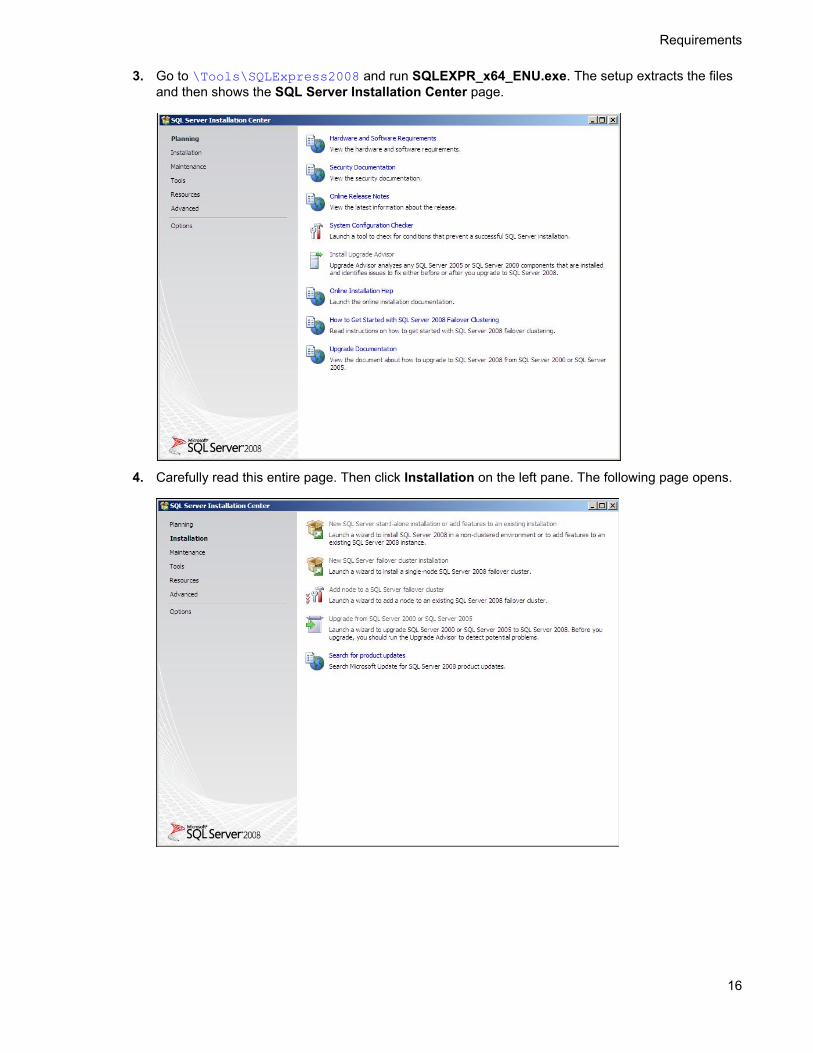
3. Go to \Tools\SQLExpress2008 and run SQLEXPR_x64_ENU.exe. The setup extracts the files and then shows the SQL Server Installation Center page.
4. Carefully read this entire page. Then click Installation on the left pane. The following page opens.

Requirements
17
5. Click the New SQL Server standalone installation or add features to an existing installation option. The setup automatically does a configuration check and shows the result.
6. Click OK. The Product Key page opens.

18
Requirements
7. Click Next.
8. Check the box beside I accept the license terms option and click Next.
9. The setup checks and prompts to install the required support files.

Requirements
19
10. Click Install to install the required files.
11. Click Next. The setup checks the Database Engine Services.

20
Requirements
12. Click Next. The Instance Configuration page opens.
13. Keep the defaults and click Next. The Disk Space Requirements page opens.
14. Verify that you meet the space requirements.

Requirements
21
15. Click Next. The Server Configuration page opens.
16. Select an account for the SQL service (for example, the built-in Network Service account). Click Next. The Database Engine Configuration page opens.
17. Click Add Current User and specify an administrator.

22
Requirements
18. Click Next. The Error and Usage Reporting page opens.
19. Click Next. The Installation Rules page opens.

Requirements
23
20. Click Next. The Ready to Install page opens.
21. Click Install to start the installation. The setup shows the installation progress.

24
Requirements
22. When installation is complete, the Complete page opens.
23. Click Close to close the installation wizard.
2-9 Disabling the Internet Explorer enhanced security configuration component
If this Windows component is enabled, you cannot install the HP CR server. After you disable the component, you must reboot your system before proceeding with the server installation.
For Windows 2008 R2, follow the instructions below to disable Internet Explorer Enhanced Security Configuration for all users.
1. Close all instances of Internet Explorer.
2. Click Start > Administrative Tools > Server Manager.
3. If a User Account Control dialog box appears, click Continue.
4. In the left pane, select Server Manager.
5. In the right pane under Server Summary, click Configure IE ESC.
6. Under Administrators, click Off.
7. Under Users, click Off.
8. Click OK.
9. Reboot your system before proceeding with the installation.

Requirements
25
For Windows 2003 Standard Edition SP2, follow the instructions below to verify that Internet Explorer Enhanced Security Configuration is disabled:
1. Click Start > Control Panel > Add or Remove Programs.
2. In the Add or Remove programs page, click Add/Remove Windows Components. The Windows Component wizard opens.
3. Scroll down the components list to find Internet Explorer Enhanced Security Configuration.
4. Verify that the component is disabled. If not, disable it.
5. Click Next, then click Finish.
6. Reboot your system before proceeding with the installation.
2-10 Enabling 8.3 name creation on NTFS partitionsYou must enable 8.3 Name Creation on NTFS Partitions to allow the Ghostscript conversion engine to work with long file names or with spaces and nonstandard characters in the file name during conversion. To do so:
1. Click Start > Run.
2. Enter regedit and click OK.
3. In the Registry Editor, go to:
HKEY_LOCAL_MACHINE\SYSTEM\CurrentControlSet\Control\FileSystem
4. Right-click the NtfsDisable8dot3NameCreation entry and select Modify from the drop-down menu. The Edit DWORD Value page opens.
5. In the Value data text box, enter 0.
6. Click OK to close the page.

26
Requirements

27
3 Installing the HP CR server
The HP CR server is installed with:
Specialized Windows services that carry out the document distribution responsibilities of the server
Components that complete message processing tasks
Connectors that connect the HP CR server with external systems that submit messages to the server and distribute them to their final destinations
HP CR Server Administrator, which is the management application for the HP CR server
The remainder of this section describes:
Installing the HP CR server (27)
Completing the server configuration wizard (31)
3-1 Installing the HP CR serverThe HP CR server setup program has a verification utility that checks the server for compliance with installation requirements. All installation requirements must be met before HP CR can be installed.
TIP: Before you start installing the HP CR server, review and verify that you have met all Requirements (7).
NOTE: If you are setting up an HP CR server cluster, review the HP Cluster Service setup instructions (see Section 14: Setting up an HP CR server cluster, 139) before beginning the HP CR server installation. If you are setting up HP CR with a Telco Connector, see Section 15: Installing and configuring a Dialogic modem driver (149) before beginning the HP CR server install.
To install HP CR server:
1. Log in to the system where the HP CR server is being installed using the HP CR service account.
2. Go to a network copy of the HP CR server and right-click on:
\MessageServer\setup.exe
Select the Run as administrator option.
The InstallShield wizard opens and configures your system for installation. When configuration is complete, you see the welcome message.
NOTE: During installation, if .NET 4.0 is not found by the installation check, it is automatically installed. The HP CR server installation screens will show only after .NET 4.0 installation is complete.

Installing the HP CR server
28
3. Click Next. The setup shows the License Agreement page.
4. Scroll down through the End-User License Agreement. Then, select I accept the terms of the license agreement.

29
Installing the HP CR server
5. Click Next. The setup shows the installation options.
NOTE: The default destination folder is: C:\Program Files(x86)\HP\HPCR You can change the destination if necessary by clicking Browse and then selecting the desired location.
6. Select one of the following:
Typical for an installation that does not support faxing from a Telco connector.
Custom to select options, such as the modem server.
If you selected Custom, select options for the HP CR server installation. The following features must always be selected:
Message Server
Connector Package
Component Package
Server Administrator
IMPORTANT: Select the Modem Server option to support faxing with a local modem server.
7. Review the results and perform one of the following listed actions.
IMPORTANT: If Microsoft Office is partially detected by the setup, exit the setup and verify that Office is configured for first-time use. Start an Office application and, if prompted, enter a user name and initials. Wait for a new document to open and then exit the Office application. If Microsoft Office is still only partially detected, verify that Word, Excel, and PowerPoint are installed and continue with the HP CR server installation.
To exit the setup or to install components that are required for the installation, click Cancel and then click Yes to exit the setup.
To continue with the installation, click Next. The setup requests logon credentials for the HP CR service account. By default, the User Name field is populated with the name of the user logged into Windows.

Installing the HP CR server
30
8. Provide the HP CR service account logon credentials:
a In the NT Domain field, enter the Windows domain name.
b In the User Name field, enter the user name.
c In the Password and Confirm Password fields, enter the user password.
d Click Next. The setup validates the user account and then displays options for the message database.
9. Complete the database configuration:
a If the setup detects Microsoft SQL Server Express 2008, verify that the Server field is populated with the name of the server running the Microsoft SQL server database application and that \SQLExpress is appended to the server name.

31
Installing the HP CR server
If the setup detects SQL Server 2008 SP2, verify that the Server field is populated with the name of the server running the Microsoft SQL server database application.
NOTE: The default value is the local server where the setup is running.
NOTE: Special instructions apply to an HP CR server cluster. For the first server being set up, enter the database server name. For the second server being set up, allow the setup to create a local database. (The second server is configured to use the database server, so the local database is not used.) For more information, refer to Section 14: Setting up an HP CR server cluster (139).
b In the Database field, review the message database name and modify it if necessary.
NOTE: During installation, the database is created on the HP CR server in:...\HP\MessageServer\Database
c Select the authentication method that the HP CR services use to access the database. Choose one of the following:
Use Windows Integrated Authentication to use the HP CR service account. This is the default.
Use SQL Authentication to use SQL server authentication. If you select this option, enter the logon credentials in the User Name and Password fields.
10. Click Next. The setup validates the connection to the database and displays installation settings.
11. Review the installation settings.
12. Click Next to proceed with the installation.
A message is displayed when installation is complete.
13. Click Finish. The setup launches the server configuration wizard (described in the next section).
NOTE: HP CR server can be found in the registry (see Note about the registry keys location for HP CR server, 32) after installation is complete.
3-2 Completing the server configuration wizardAfter the HP CR server is installed, the server configuration wizard launches automatically. The server configuration wizard must be completed before starting the HP CR Server Administrator.
1. Verify that the server configuration wizard has opened and is showing a welcome message.
IMPORTANT: When setting up the passive server in an HP CR server cluster, exit the server configuration wizard and click No when prompted to run the wizard again when HP CR Server Administrator starts. See Section 14: Setting up an HP CR server cluster (139) for additional information.
2. Click Next. A message indicates the server configuration is completed.
3. Click Finish to close the wizard.

Installing the HP CR server
32
The server configuration wizard saves the configuration and starts the HP CR Server Administrator.
When the HP CR Server Administrator is closed, Microsoft Management Console displays a message about saving changes to the MSC file. This file records the current position of items in the console tree. To preserve the console state, save the changes.
If prompted to update the MSC file, click Yes.
3-2-1 Note about the registry keys location for HP CR serverThe 64-bit operating system stores registry keys for 32-bit applications under Wow643Node. Therefore, when installing HP CR server, the HP CR registry keys are located in:
HKLM\SOFTWARE\Wow6432Node\Omtool

33
4 HP CR post installation review and configurations
The HP CR Server Administrator can be used for:
Modifying the HP CR Server Administrator (33)
Modifying components (56)
Modifying connectors (64)
Implementing and configuring the HP CR Intelligent Device Client (71)
4-1 Modifying the HP CR Server AdministratorThe HP CR Server Administrator is used for many functions with the HP CR server, such as to configure and manage connectors, configure and manage components, add group permissions, and dispatch rules. To launch the HP CR Server Administrator:
Click Start > All Programs > HP Capture and Route > HP Capture & Route Server Administrator.
As described in this section, HP CR Server Administrator modifications include the following:
Activating the server license (33)
Specifying the originator of notification messages (35)
How the routing rules work after installation (36)
Configuring group permissions (37)
Managing the Web Client views (55)
Managing devices (55)
The HP CR Server Administrator also can be used to monitor message traffic and MFP device configuration. For details related to these tasks, refer to the HP CR administrator on-line help.
4-1-1 Activating the server licenseAfter installation, the server uses a 60-day demonstration license. At some point during this time, the server license should be activated. This can be done automatically or through a manual method, depending on whether the HP CR server has access to the internet.
4-1-1-1 Automatic license activation
Have available a copy of the Activation Code received with the software package.
1. Launch HP CR Server Administrator and expand the tree view.
2. Select the server name. Right-click and select Licensing...
3. Click the Activate License... button.
4. Select the Automatically activate via the Internet option.
5. Paste the Activation Code in the Activation Code page.

34
HP CR post installation review and configurations
6. Click OK. The server is updated with the new license.
7. Click Close to complete the procedure.
4-1-1-2 Manual license activation
Have available a copy of the Activation Code received with the software package.
1. Launch HP CR Server Administrator and expand the tree view.
2. Select the server name. Right-click and select Licensing...
3. Click the Activate License... button.
4. Select the Export activation file for manual activation option.
5. Browse to a location to save the file.
6. From a system with internet access, launch the web browser and go to:
https://license.omtool.com/manual
The Manual License Portal page opens.
7. Paste the Activation Code in the Activation Code page.
8. Browse to the ManualActivation.exp file created in Step 5. Click Upload, then click NEXT.
9. Click Download and save the ManaulActivation.imp file to a location available on the HP CR server.
10. From the HP CR Server Administrator, select the server name. Then, right-click and select Licensing...
11. Select the Activate License... button.
12. Select the Import activation file from manual activation option.
13. Browse to the saved ManaulActivation.imp file.
14. Click OK. The license has been updated.
15. Click Close to complete the procedure.

HP CR post installation review and configurations
35
4-1-2 Specifying the originator of notification messagesThe HP CR server generates notification messages for various events and sends them to users through the HP CR connectors for SMTP. The display name and email address associated with these notification messages can be set in the HP CR server properties. It is recommended that these attributes are set using a valid email address so users can reply to notification messages if they require assistance. (The default display name is Message Server and the default email address is MessageServer.)
To specify the originator of notification messages generated by the HP CR server:
1. Launch HP CR Server Administrator and expand the tree view.
2. Right-click the HP CR server in the console tree and select Properties. The Server Properties page opens.
3. Click Settings.
4. In the Email Address text box, enter the email address that should be associated with notification messages generated by the HP CR server.
5. In the Display Name text box, enter the name that should be associated with notification messages generated by the HP CR server.
6. Click OK to save changes to the server properties.

36
HP CR post installation review and configurations
4-1-3 How the routing rules work after installationWhen a message arrives on the HP CR server via a connector, the server tries to match the message to the most appropriate routing rules to determine how it should be processed. When the message matches a routing rule, the HP CR server begins processing the message according to the instructions associated with that rule. Some routing rules are created automatically when you install the HP CR server.
Routing rules can be inbound or outbound.
Inbound Faxing - The Inbound folder in the console tree defines all of the inbound fax routing rules. The HP CR server uses the inbound rules when processing inbound fax messages. The rules are listed in the same order they are used in processing messages.
Outbound - The Outbound folder in the console tree lists all outbound rules defined for the HP CR server and uses the outbound rules to process outbound messages. The rules are listed in the same order they are used in processing messages.
You can associate up to five criteria with a rule. If you want to set more than five criteria for a rule, create the rule with the first five criteria, make a copy of the rule, add the next five criteria, and so on.
Routing rules are preconfigured after installation. Only custom rules need to be created.

HP CR post installation review and configurations
37
4-1-4 Configuring group permissionsThe configuration node allows the HP CR Server Administrator to configure group permissions as well as custom options, validators, properties, and Web Client views. Details can be found below, as well as in the HP CR administrator on-line help (“Configuring group user permissions” topic).
The server functions that use group access permissions are:
Clients - determines whether the members of the group have permissions to use the end user interface client
Prompts - determines what pre-configured prompts the members of the group can use
Scan Settings - determines whether the members of the group can use and configure scan settings for a particular device or device group
Custom Options - determines what configured custom options the members of the group can use
Printers - indicates configured printers that are available as a destination by members of the group
Folders - indicates configured folders that are available as a destination by members of the group
4-1-5 Adding and configuring network printers for groups
4-1-5-1 Adding network printers
The HP CR End User Interface will read the list of configured network printers on the HP CR server. Before the network printers are listed in the HP CR End User Interface, the network printers must be added to the Printers tab in the Groups section of the HP CR Server Administrator, as described below.
1. Install the printer driver on the HP CR server using the standard Windows installation procedure.
2. Launch HP CR Server Administrator, expand the tree view, and click Configuration > Groups.
3. In the right pane, double-click on the Default group (or applicable group). The Group page is displayed.
4. Click on the Printers tab.

38
HP CR post installation review and configurations
5. Select Enable members of this group to select the specified Printers.
6. Click the Add button. The Add Printer page is displayed.
7. Enter the printer information. For example:
8. Click OK. Click OK again to save the changes. Refer also to Selecting a network printer (109).
4-1-5-2 Modifying network printer properties
1. Launch HP CR Server Administrator, expand the tree view, and click Configuration > Groups.
2. In the right pane, double-click on the Default group (or applicable group).
3. Click on the Printers tab.
4. Highlight the printer that needs to be modified and click Properties.
5. On the Edit Printer page make all needed changes and, when finished, click OK.
6. Click OK again to close the Group page.

HP CR post installation review and configurations
39
4-1-5-3 Removing a network printer
1. Launch HP CR Server Administrator, expand the tree view, and click Configuration > Groups.
2. In the right pane, double-click on the Default group (or applicable group).
3. Click on the Printers tab.
4. Highlight the printer that needs to be modified and click Remove.
5. Click OK to close the Group page.
4-1-6 Adding and configuring network folders for groupsIn certain capture scenarios it is desirable for the HP CR server to impersonate the user who has submitted the document for processing when uploading that document to network storage. When a user logs into a device and provides both a network user name and password, the HP CR captures those credentials in a secure manner and passes them to the HP CR server. The server can then use the credentials to log in as that user when uploading the delivered document to a network folder.
NOTE: Capture and use of login credentials requires configuration for the device buttons as well as the correct permissions for the account used in delivering to the network storage.
4-1-6-1 Requirements for using a folder (UNC or FTP)
When using a network folder, be sure the following requirements are met:
The folder is remote from the HP CR server
The folder has appropriate permissions for user access
4-1-6-2 Adding a network folder
1. Launch HP CR Server Administrator, expand the tree view, and click Configuration > Groups.
2. In the right pane, double-click on the Default group (or applicable group).
3. Click on the Folders tab on the Group page.
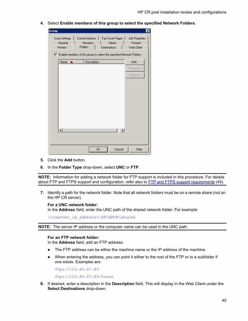
40
HP CR post installation review and configurations
4. Select Enable members of this group to select the specified Network Folders.
5. Click the Add button.
6. In the Folder Type drop-down, select UNC or FTP.
NOTE: Information for adding a network folder for FTP support is included in this procedure. For details about FTP and FTPS support and configuration, refer also to FTP and FTPS support requirements (45).
7. Identify a path for the network folder. Note that all network folders must be on a remote share (not on the HP CR server).
For a UNC network folder:In the Address field, enter the UNC path of the shared network folder. For example:
\\<server_ip_address>\HP\HPCR\shared
NOTE: The server IP address or the computer name can be used in the UNC path.
For an FTP network folder:In the Address field, add an FTP address.
The FTP address can be either the machine name or the IP address of the machine.
When entering the address, you can point it either to the root of the FTP or to a subfolder if one exists. Examples are:
ftp://123.45.67.89
ftp://123.45.67.89/Sales
8. If desired, enter a description in the Description field. This will display in the Web Client under the Select Destinations drop-down.

HP CR post installation review and configurations
41
9. You can select one of two methods to connect to the folder:
Service Account - The service account that starts the HP CR services will need permissions to the folder. When a document is stored in this folder, the service account is the user responsible for storing it.
Specific Account - Enter a user name and password. Regardless of who was authenticated at the device, this specific user will store the document in the folder and requires permissions at the operating system level.
For FTP support, add a Specific Account user to connect to the FTP. Ensure that this user has privileges to write to the FTP site.
In addition, you can select:
Use user supplied credentials if available - When a user authenticates to the device, this authentication is passed through to be used to store the document to a folder. If the authentication is not available, such as when a feature that does not require authentication is selected, either Service Account or Specific Account will be used (whichever is selected).
FTP Settings - Use these options to further define the FTP destination.
NOTE: For FTPS, select the Explicit TLS (Connects on port 21) option.
Example for a UNC folder:

42
HP CR post installation review and configurations
Example for an FTP folder:
10. Click OK to return to the Group page.
11. Click OK again to save and close the Group page.
12. To capture the user’s credentials at the device, the device feature will also need to enable the Capture user password feature. To configure Capture user password at the device:
a Expand the Devices node.
b Right-click the Group that the device belongs to and select Properties.
c Click the Buttons tab.

HP CR post installation review and configurations
43
d Select a feature that will capture the user password (such as Personal Distributions).
e Click Properties.

44
HP CR post installation review and configurations
f Select the Require authentication and Capture user password options at the bottom of the screen.
g Click OK to close the Button Properties page.
Repeat Steps d through g for any features that capture the user’s credentials at the device.
NOTE: If the Connect Using folder settings are changed, any previously created distributions will need to be updated to reflect the changes.
13. Click OK to close the Device Group Properties page.
NOTE: Permission (at the share level) for capture and use of user credentials requires that the user account specified or the group the user belongs to has read/write privileges.
4-1-6-3 Modifying network folder properties
1. Launch HP CR Server Administrator, expand the tree view, and click Configuration > Groups.
2. In the right pane, double-click on the Default group (or applicable group).
3. Click on the Folders tab.
4. Highlight the folder name that needs to be modified and click Properties.
5. On the Edit Folder page make all needed changes and, when finished, click OK.
6. Click OK again to close the Group page.
HP CR post installation review and configurations
45
4-1-6-4 Removing a network folder
1. Launch HP CR Server Administrator, expand the tree view, and click Configuration > Groups.
2. In the right pane, double-click on the Default group (or applicable group).
3. Click on the Folders tab.
4. Highlight the printer that needs to be modified and click Remove.
5. Click OK to close the Group page.
4-1-7 FTP and FTPS support requirementsIf you will write documents to a network folder using FTP or FTPS, the following are required:
FTP server
HP CR End User Interface client
HP MFP device configured with the Embedded Device Client for HP OXPd (any model)
The remainder of this section describes:
FTP support configuration (below)
FTPS support configuration (47)
Sending to an FTP(S) destination in the Web Client (49)
Sending to an FTP(S) destination on an HP MFP (52)
4-1-7-1 FTP support configuration
Installing and configuring a Filescan connector for FTP support
The Filescan connector is installed by default.
Do not set the Filescan connector to virtual mode.
Leave the folder path as the default folder path defined during installation.
NOTE: When the Filescan connector is created, a default Filescan rule is created. The FTP destination will match this rule and be delivered for the final destination using the default.

46
HP CR post installation review and configurations
There is no special Filescan rule that needs to be created in order for FTP support to function.
Setting up and configuring the FTP server
1. Install an FTP on the HP CR server (or remotely).
2. Configure the server and assign users.
Configuring FTP support
FTP support is installed, by default, for HP CR. To verify that FTP support is installed properly, complete the procedure in Adding a network folder (39), if you have not already done so.
Enabling an FTP destination for use with the Web Client
1. In the tree view, click Configuration > Groups and select the Default group.
2. Double-click a group to display the Group properties dialog.

HP CR post installation review and configurations
47
3. Click on the Clients tab and select the Enable members of this group as users option.
4. In the Allow group to route to list, locate Network Folder and enable it.
5. Click OK to finish.
4-1-7-2 FTPS support configuration
Setting up and configuring FTP server for FTPS support
1. Launch server manager.
2. Navigate to Roles > Web server(IIS).
3. Click on Add Role Services.
4. Select the FTP server and click on Install.
FTP server is installed on the HP CR server.
Creating an FTPS site
1. Launch Internet Information Services (IIS) Manager.
2. Double-click on the Server Certificates and create the “Self-assigned” certificate.
3. Expand the tree view and, in the Connections pane, expand the tree for the server name. Select Sites.
4. From the Actions pane, select Add FTP Site.

48
HP CR post installation review and configurations
5. Complete the Add FTP Site wizard:
a In the FTP site name field, enter a name for this FTP site.
b In the Physical path field, enter the location of your site or where you want the FTP site files to go.
c Click Next.
d Set the IP address that you want to use for FTP.
e Select Allow SSL.
f Select the created “Self-assigned” certificate from the SSL Certificate drop-down list.
g Click Next.
h Select Basic authentication.
i Select All users on the Allow access to drop-down.
j Select Read and Write from Permissions.
k Click Finish.
You should see the name of your FTP site under the main Sites pane.
6. Double-click on the FTP site that you set up from the main pane, or expand Sites from the tree view and select the FTP site that you set up.
7. Check folder permissions on the folder to which you pointed the FTP site:
a Click Edit Permissions under the Actions pane.
b Click the Security tab. Add Everyone and give all permissions to it.
c Make sure the user that you created above has modify rights to the folder.
8. With the FTP site that you created above selected in the IIS Manager, launch the FTP User Isolation module by clicking on the FTP User Isolation icon.
9. Change the isolation method from FTP root directory to User name directory (disable global virtual directories).
10. Click Apply under the Actions pane.
11. Go back to the root of your FTP Site.
12. Create a virtual directory named Local User (for example: User A):
a Right-click on Test FTP Site from the tree view and select Add Virtual Directory.
b Enter the Alias as LocalUser (for example: User A). Note that this name is case-sensitive.
c Enter the Physical path as the path given for FTP site. For example:C:\inetpub\ftproot
d Click OK.
13. Authorize the domain users in FTP:
a In IIS Manager, select your FTP Site and then the FTP Authorization Rules module.
b You can authorize users to access the FTP site using one of these options:
Add the individual users or groups.
Allow all authenticated users. By default, individual users or a user group are added when setting up isolated users.

HP CR post installation review and configurations
49
Testing the FTPS connection
To test the FTPS connection, install FileZilla Client.
1. Install FileZilla(3.5.3).
2. Launch FileZilla.
3. Navigate to File > Site manager > New Site.
4. Provide the details for the respective fields and click Connect.
FTPS site will be connected to the specified path.
FTPS support configuration on the HP CR server
FTP support is installed, by default, for HP CR. To verify that FTP support is installed properly, complete the procedure in Adding a network folder (39), if you have not already done so.
4-1-7-3 Sending to an FTP(S) destination in the Web Client
1. Install and configure the HP CR Web Client.
2. Open the Web Client.
3. Select Messages > New.
4. In the New Message dialog, select Network Folder as the Type.

50
HP CR post installation review and configurations
5. In the Select destination drop-down, select the FTP folder.
6. Complete all needed fields to send a message, then send the message to the HP CR server.
The job will be delivered to the destination via FTP with the following Recipient properties:
General

HP CR post installation review and configurations
51
Attachments
Template

52
HP CR post installation review and configurations
The attachment will be delivered to the FTP destination that was specified when creating the network folder in the HP CR server.
4-1-7-4 Sending to an FTP(S) destination on an HP MFP
Method One: Creating an Embedded Directive for use with FTP(S)
1. Open the Web Client and select Distributions > New.
2. In the New Message dialog, select Network Folder as the Type.
3. In the Select destination drop-down select the FTP folder.
4. Complete all needed fields to send a message, and then send the message to the HP CR server.
5. Walk up to the HP MFP.
6. Select Public Distributions (or Personal Distributions).
7. Select the newly created Embedded Directive that will be using FTP.
8. Scan a document.
Method Two: Creating a new button on the device using FTP(S) to a network folder
1. From the Web Cient, create an Embedded Directive that:
Is public (published). In this way when it is used, the job will be from the scanning user rather than the Embedded Directive owner.
Routes to the Network folder using FTP.
2. Right-click on the device group and select Properties.
3. Click on the Buttons tab and select Add.
4. In the Add Button dialog, select Scan to Distribution in the Type drop-down.
5. Enter a Name for the button and click OK.

HP CR post installation review and configurations
53
6. In the Device Home Screen tree view, select the new button that was just created and click the Properties button.
7. When the Button Properties dialog opens, click the Options tab.

54
HP CR post installation review and configurations
8. To choose a Scan Distribution, click the Select button.
9. Search for and locate the Embedded Directive that will send via FTP to a network folder.
Highlight the Embedded Directive and click Select.
10. Click OK to complete the setup.
A new button will be available on the device that will use FTP to scan to a network folder.

HP CR post installation review and configurations
55
4-1-8 Managing the Web Client viewsYou can specify the Web Client view that will be used by members of a group. This enables members of the group to set up options to customize the HP CR End User Interface. See Optional configuration - Customizing the HP CR End User Interface (112).
1. Launch HP CR Server Administrator, expand the tree view, and click Configuration > Groups.
2. In the right pane, double-click on the Default group (or applicable group). The Group page opens.
3. Click on the Web Client tab.
4. Select Enable members of this group to use the following web view.
5. Select the appropriate XML for the Web Client view.
6. Click OK to close the Group page.
4-1-9 Managing devicesThe Devices node enables you to manage devices and create groups of devices with customized buttons. Refer to the HP Capture and Route (HP CR) Embedded Device Client for HP OXPd Installation Guide.

56
HP CR post installation review and configurations
4-2 Modifying componentsWithin the HP CR server, the components perform functions such as composing the message into the format appropriate for the method of delivery, modifying the fax number if necessary, and determining whether a message requires status or fax preview processing. All components are managed by a Windows service called the Component Manager that manages the flow of messages through the components and processing steps of a message.
The following are automatically installed with the HP CR server:
Billing component (56)
Compose component (57)
Data Extractor component (60)
Dispatch component (60)
Embedded Directive Manager component (60)
Lookup Manager component (61)
Maintenance component (62)
Notification component (63)
Preview Manager component (63)
4-2-1 Billing componentThe Billing component extracts data from messages and populates a table in the Archive database with this information. The Billing component should be used for the Job Based Accounting function of HP Access Control. To configure the Billing component:
1. Launch HP CR Server Administrator, expand the tree view, and click Components. The Components are listed in the details pane.
2. Double-click Billing to open the Properties for Billing page.
3. Click Configuration.
4. Select the Enable collection of billing data option to enable billing.
5. Configure information in the Database section. Modify the Data Source Name (DSN) to point to an external ADO compatible database. By default, the DSN points to the HP Archive Database which includes a table to collect all Job Accounting data.
6. Verify that the CostRecoveryData table is selected in the Table drop-down menu. For information on this table, click .../About_the_CostRecoveryData_table.htm. If needed, select another table. The choices are ArchiveTable and <No table selected>.
7. In the Select the columns to populate section, uncheck the columns that should not be populated in the table. By default, all columns are selected.
Any column you do not select will not have data entered for it and must be either null or have defaults configured in the table itself. When writing a billing record, if you do not have a value for that column or you are not configured to place a value into a column, the null or default specified value is inserted in the column.
You must always have the following columns selected:
prDateBilling - The value for this string is the billing date.
prGUID - The value for this column should be nvarchar and is limited to 36 characters.

HP CR post installation review and configurations
57
If you do not select these columns, you will see an error message indicating that the minimum requirements have not been met.
NOTE: Information in a Date field applies to the prDateSubmitted table in the database.
8. Click OK to save your changes.
4-2-2 Compose componentThe Compose component (Composer) can deliver the original format or convert input (source) files from one file type into another file type (final file format). For example, when a PDF file is sent as a fax message, the file is converted into a final format of TIFF. The HP CR server supports the following final formats:
DOC/DOCX (OCR text)
PDF (text)
PDF (image)
PDF (image + hidden text)
PDF/A (image + text)
PDF/A (OCR text)
RTF (OCR text)
TIFF (image, single-page)
JPEG (image, single-page)
TXT (OCR text)
XLS/XLSX (OCR text)
XPS (OCR text)

58
HP CR post installation review and configurations
In addition to composing into various formats, the Composer can be used to:
Apply document compression.
Meet the archiving standards set for composing to PDF/A formatting.
4-2-2-1 Configuring the Compose component for Microsoft Office automation
The Compose component can be configured to convert documents using the “Automation” conversion method, which utilizes a document’s native application to open the document so that it can be converted to the required delivery format. Automation is the recommended conversion method for Microsoft Office documents, because this method produces the highest quality conversion results and eliminates conversion errors that can occur with other methods.
NOTE: The following procedure is optional. However, for best results this procedure is highly recommended if you have Microsoft Office installed on the server. If Office is not being used in the LAN, or if automation is not the preferred method for converting Office documents, skip the following procedure.
The Compose component manages conversion methods for all Composers for the HP CR server, so it is necessary to complete this procedure only once. To configure the Compose component to use the automation conversion method:
1. Verify that a supported version of Microsoft Office is installed on the HP CR server. For supported Office versions, see Additional installation requirements (9).
2. Launch HP CR Server Administrator, expand the tree view, and click Components.
3. Double-click Compose. The Properties for Compose page is displayed.
4. Click the Conversions tab.

HP CR post installation review and configurations
59
5. Enable automation for DOC files. To do so, select doc.
6. Click Properties, select Word Automation (the Conversion Engine), and click OK.
7. Repeat the previous step for DOCX, PPT, PPTX, XLS, and XLSX file types (selecting the appropriate Conversion Engine for each).
NOTE: DOCX, PPTX, and XLSX are file types associated only with Office 2007. DOC, PPT, and XLS files are file types associated with Office 2003 and earlier, and are also compatible with Office 2007.
8. Click OK to save changes to the Compose component.
NOTE: The third-party conversion engine (Aspose) that HP CR uses by default for MS Office documents supports documents from Office 97 and later. Also note that when converting a DOC file to PDF using the Aspose engine, if the file includes comments with text strike-through, the PDF file does not show the strike-through marked on the contents in the document.

60
HP CR post installation review and configurations
4-2-2-2 Configuring additional Compose component features
Refer to the Compose component topics in the HP CR administrator on-line help.
4-2-3 Data Extractor componentThe Data Extractor component allows for the extraction and mapping of barcode data from documents that pass through the HP CR.
This component can be set with a Regular Expression designed to detect a preset value in the third party vendor barcodes. The advantage of using Regular Expressions is that it allows HP CR to support third party vendor barcodes without the need for software updates.
How the Data Extractor component works after installation
The data extractor is enabled by default. To configure it for use with Regular Expressions, refer to the HP CR administrator on-line help (“Configuring the Data Extractor with regular expressions” topic).
4-2-4 Dispatch componentThe Dispatch component determines the final system destination for each message. The final system destination is the part of the HP CR server that routes a message to its intended recipient (also known as the recipient destination). The recipient destination is an email address, fax number, folder name, or printer name. The Dispatch component also normalizes the phone number for outbound faxes.
How the Dispatch component works after installation
Dispatch is set up completely for all installations. There is no need to configure this component beyond the default setup.
The Dispatch component converts a destination number into a fully qualified number that would be meaningful to someone located anywhere in the world. To review normalization properties and rules, refer to the HP CR administrator on-line help.
4-2-5 Embedded Directive Manager componentThe Embedded Directive Manager component manages embedded directives for the server, and performs tasks such as:
Creating embedded directives for Routing Sheets and managing them for the server. (You must use the HP CR Client to generate a Routing Sheet.)
Detecting and decoding embedded directives in Routing Sheets. (If a document with a Routing Sheet enters the server via a network scanning device, the Routing Sheet must be the first or last page in the scanned document.)
Applying embedded directives to messages. (You can create a embedded directive using the HP CR Client, and then apply the embedded directive to documents via inbound or outbound rules.)
You can have only one instance of this component. You cannot modify this setting.
How the Embedded Directive Manager component works after installation
The Embedded Directive Manager can scan outbound messages for embedded directives and decodes them after you create one or more outbound routing rules. These rules specify the criteria for messages the HP CR server will route to the Embedded Directive Manager.
For more information, refer to Embedded Directive Manager topics in the HP CR administrator on-line help.

HP CR post installation review and configurations
61
4-2-6 Lookup Manager componentThe Lookup Manager component matches DID extensions to the appropriate HP CR user. This component uses LDAP to find matches to user objects stored in Microsoft Active Directory. The Lookup Manager component can route messages to multiple users that all share the same extension number. For example, if one DID extension is assigned to five users, the Lookup Manager component routes all messages destined for that DID extension to all five users.
How the Lookup Manager component works after installation
DID lookup must be manually configured in the SMTP connector after installation if inbound faxes are being routed to users via the Lookup Manager.
To configure the Lookup Manager component:
1. Launch HP CR Server Administrator, expand the tree view, and click Connectors. The details pane lists the connectors that are licensed with your server.
2. Double-click the SMTP connector to open the Properties page.
3. Select the box beside Enable DID Lookup via this connector option if it is not checked.
4. Click DID Lookup.
5. Click Add. The LDAP Properties page opens.
6. In the General section, enter the following information.
In the Server Address text box, enter the name of the lookup server.
In the Port text box, enter the port number. The port number can be 389 (LDAP), 636 (secure LDAP), or 3268 (Active Directory).
In the Description text box, enter a brief description.
7. In the Logon section, enter the following information:
Select User if you want to log onto the lookup server as a specific user (the default is Anonymous).
In the Username text box, enter the user name.
In the Password text box, enter the user password.
If you select User, you must look at the Username field. Lookups in this search base should be successful with no additional configuration if this field contains a user ID formatted using the Active Directory logon format (for example: [email protected]). If this field contains a user ID in any other format (for example: domain\user), select Bind using Windows generic security services.
8. Click Search.
9. In the General section of the Search page, enter the following information:
In the Search Timeout text box, enter the number of minutes the server should search before timing out. The timeout period you define on the lookup server should not be longer than the Search Timeout setting for the connector. You must also consider the scope of your search base when configuring the timeout setting. If the search base is broad, configure a longer timeout period since the lookup might take a relatively longer amount of time.
In the Search Base text box, enter the search base string. Use LDAP format. For example: ou=mysite,o=com
In the Search Filter section, define the search filter.
If you want to use a simple filter, do the following:

62
HP CR post installation review and configurations
Select Use simple filter.
Select Wildcard match ending on received DID if you want the search filter to match all received DID numbers. Or, select Match last [ ] digits of received DID and type a number in the spin box if you want the search filter to match only the specified number of digits at the end of the DID string.
Select Return people only if you want the query to return only users associated with this connector. (This option will exclude printers, computers, and other resources from the search results.)
Select an option in Attribute holding fax number. The option you select is the field in the database that the connector queries.
If you want to use a custom filter, do the following:
Select Use custom filter.
Click Properties.
Type the custom search filter in the Filter text box. (Use the guidelines provided in the Custom LDAP Filter screen.)
Click OK.
10. In the Filter section, click Test. The Lookup Test page opens.
11. Enter a DID number in the Enter the incoming DID text box. Click Search. Query results appear.
12. Click Close to return to the LDAP Properties page.
13. Click OK. Click OK to close the SMTP Properties page.
TIP: It is recommended that you index the database field containing DID numbers. This optimizes the speed of lookups.
For information about simple and custom LDAP filters, refer to the HP CR administrator on-line help.
4-2-7 Maintenance componentThe Maintenance component:
Removes old messages from the history folder. The retention period is set by the administrator.
Archives processed messages based on desired archives (including successfully sent messages, failed messages, and all received messages).
Archiving allows for longer retention periods by storing all messages and their corresponding documents and data in a network file and/or SQL database as an archived ZIP file.
How the Maintenance component works after installation
The administrator will need to create and schedule the cleanup and archive tasks after installation. To configure cleanup for the HP CR server:
IMPORTANT: You cannot run cleanup from a Remote Administrator. You must run cleanup through the HP CR Server Administrator.
1. Launch HP CR Server Administrator, expand the tree view, and click Components. The components are listed in the details pane.
2. Double-click the Maintenance component to open the Properties page.
3. Click the Cleanup option.

HP CR post installation review and configurations
63
4. In the Queues section, select the number of days the Maintenance component should leave messages in the HP CR server database before deleting them in the Remove messages older than [...] days option.
5. Select the check box beside the Remove messages that failed to archive option if you want the Maintenance component to remove messages that failed to archive.
6. In the Billing section, check the box beside the Remove entries older than [...] days option to run cleanup on billing records in the HP CR server database. Enter the appropriate number of days in the spin box (the default is 180 days).
7. In the Connector and Component Journals section, select the check box beside the Remove billing records after [...] days option to run cleanup on messages in the connectors, components, and the journals in the HP CR server database. Enter the appropriate number of days (default is 60).
8. Click OK to save your changes to the Maintenance component.
When cleanup runs, items are marked for deletion and deleted at 5am the following day.
For information about setting up and configuring archive, refer to the HP CR administrator on-line help.
4-2-8 Notification componentThe Notification component delivers a notice about the status of a message to the person who sent the message. Notification is sent for outbound messages only, or messages that originate within the HP CR server.
How the Notification component works after installation
Notification is set up by default. No additional settings are required.
For information about working with notification messages, refer to the HP CR administrator on-line help.
4-2-9 Preview Manager componentThe Preview Manager component determines whether or not outbound messages require preview.
Outbound faxes requiring preview - If an outbound message requires preview, the HP CR server generates and sends a notification message to the sender. The notification message indicates that the outbound message is waiting to be previewed and provides a link to the message in the HP CR Client. Then the Preview Manager component holds the outbound message until it has been accepted or declined, or until it expires.
Outbound faxes not requiring preview - If an outbound message does not require preview, the HP CR server continues processing it for delivery.
NOTE: Only HP CR servers with the Web Client support the functionality associated with this component.
How the Preview Manager component works after installation
The Preview Manager is set up by default. You can have only one instance of this component. You cannot modify its settings.
For information about enabling preview in the Preview Manager, refer to the HP CR administrator on-line help.

64
HP CR post installation review and configurations
4-3 Modifying connectorsConnectors are the means by which messages enter and leave the HP CR server. With a connector, HP CR can communicate with external messaging systems. Depending on the system, it can either accept, deliver, or accept and deliver a message. All connectors are managed by a Windows server service called the Connector Manager, which engages connectors as needed, and transfers messages between the other systems and the HP CR server. HP CR will deliver documents to the following recipient types through its connector subsystem:
Microsoft SharePoint document library
Network folder
Self (delivered as an email attachment to the Windows home folder or personal Web folder accessed through the HP CR End User Interface)
Fax
Remote print
HP CR can also capture and store a document and any meta-data related to a document that has been captured from the users or extracted from the document as part of its processing. Documents and meta-data can be stored in SQL databases, or saved in XML format and stored on network folders. Database or XML output from HP CR is one method to support integration with most archive, content management, workflow, or other information system. This allows HP CR to serve as the platform for all distributed document capture and routing requirements.
The Connector Manager for HP CR is also the means by which new information systems and extensions are made available as upgrade options.
The following are automatically available with the HP CR server:
Database connector (65)
Document Management System (DMS) connectors (65)
WorkSite (DMS) connector (66)
FileShare (DMS) connector (66)
SharePoint (DMS) connector (66)
XMLStore connector (66)
Fax connector options (67)
HP LAN Fax connector (67)
Telco connector (67)
T.37 Fax connector (68)
Filescan connector (68)
HP CR Server connector (69)
Printer connector (69)
SMTP connector (70)
XMLScan connector (71)

HP CR post installation review and configurations
65
To view or modify a connector:
1. Select the connector.
2. Right-click and select Properties on the drop-down menu.
4-3-1 Database connectorThe Database connector allows you to route inbound messages (documents and faxes) from the HP CR server to a SQL database.
NOTE: A Database connector can route inbound messages to only one table in a database. If you want to route messages to more than one table in your database, you must add an additional Database connector (one for each additional table) to your environment.
How the Database connector works
Requirements for the Database connector are that you must have the following installed and configured before you can install and use a Database connector:
Database - By default, the installation sets up and configures a database during the server install.
If you choose to use another SQL database, the database must have all the required field names and any optional field names that correspond to the data you want to store. For instructions on setting up a database, see the HP CR administrator on-line help (Creating a Database for the Database Connector” topic).
Connection String - By default, the installation sets up and configures the connection string to the database created during the server install.
The connection string and table name, must be provided along with where you want to store the actual messages (in a folder or in the database). For instructions on how to create the connection string, see the HP CR administrator on-line help (“Guidelines for Creating a Database Connection String (Database Connector)” topic).
If you choose to store messages in a folder, the Database connector saves information about the messages (including the network path to the actual message) in the database while saving the actual messages in the folder you select.
If you choose to store the messages in the database, the Database connector saves information about messages and the actual messages in the database as binary data.
Inbound Routing Rule - You must create an inbound routing rule. This rule will identify messages matching a specified criteria and routes them to the database via the Database connector. For instructions on creating an inbound routing rule, see the HP CR administrator on-line help (“Creating an Inbound Routing Rule for the Database Connector” topic).
4-3-2 Document Management System (DMS) connectorsThe Document Management System (DMS) connector routes documents from the server to your company DMS. The following document management systems (DMSs) are supported:
Autonomy iManage WorkSite
Windows FileShare
Microsoft SharePoint Server 2007, Microsoft SharePoint Server 2010
XMLStore

66
HP CR post installation review and configurations
4-3-2-1 WorkSite (DMS) connector
HP CR supports integration with HP Autonomy iManage WorkSite, an information management module used to retain and track all content while enabling accessibility to authorized individuals from any device or access point. HP CR with the WorkSite connector allows users to send both soft copy and hard copy documents to Autonomy iManage WorkSite quickly and easily. And, there is no learning curve for users—HP CR works with the Autonomy iManage WorkSite’s native windows that are familiar to users.
The WorkSite (DMS) connector is automatically installed with the HP CR server. See HP CR for Autonomy WorkSite (125) for more details.
4-3-2-2 FileShare (DMS) connector
The FileShare connector stores documents in a shared network folder. The documents are routed to the folder after matching on an outbound routing rule. The folder must be set up with the correct sharing permissions for all the users who should have access to the FileShare folder.
Additional configuration
By default, the installation creates a FileShare directory and is configured on the local system. You must:
1. Specify the location of the FileShare directory using the IP address, not a UNC path.
2. Set permissions for the ...\Program Files\Common Files\HP\HPCR directory. The Domain Users group (or other appropriate user group) requires read/write permissions to this directory.
4-3-2-3 SharePoint (DMS) connector
HP CR provides tight integration with Microsoft SharePoint through SharePoint’s native interfaces. Users can upload scanned documents directly into SharePoint document libraries from an HP MFP or other scanning device.
How the SharePoint connector works after installation
The end-user specifies a target SharePoint server and library and values for any meta-data field by using HP CR Extensions for Microsoft SharePoint, a required component for integration with SharePoint. These extensions are installed onto a SharePoint server and provide users with an “Upload Scan” option from within the end user, browser-based interface to SharePoint document libraries. The user can enter a document file name, choose a document file format, and enter values for any index fields appropriate for documents uploaded to that library. The user can then choose to publish that information as a Personal Scan Reservation (making it accessible as a one-touch scanning option at an MFP device) or print a barcode scan Routing Sheet to use with the scanned hardcopy document. In either case, the HP CR server will upload the scanned document directly into the SharePoint document library at that location with the specified document name and meta-data field values.
4-3-2-4 XMLStore connector
The XMLStore connector enables HP CR to support integration with external software systems. HP CR integrates with these systems so that documents captured through HP CR can be transferred to the third party system for processing.
HP CR and third party system integration uses HP CR’s XMLStore connector to output scanned documents and meta-data to a target network folder which is monitored by the third party system as a source for incoming documents to process. The XMLStore connector stores a scanned document as well as an XML file which may include meta-data regarding the scanned document. The XMLStore is configured to use an XSLT, which formats the output meta-data from the HP CR server in a documented format that can be parsed and imported to the third party system.
For details, refer to XMLStore connector topics in the HP CR administrator on-line help.

HP CR post installation review and configurations
67
4-3-3 Fax connector optionsHP CR provides fax capability to devices and users within an organization without the need for devices to have internal fax modems connected to analog phone lines. HP CR supports:
Legacy network fax servers using the proprietary HP LAN fax protocol, used by the HP DSS product to interface to network fax servers
Voice over IP (VOIP) gateways using the T.38 internet faxing standard
Internet-based fax services using the T.37 internet faxing standard
4-3-3-1 HP LAN Fax connector
When considering how the HP LAN Fax connector works after installation, the following is the basic workflow the HP LAN Fax connector uses to send a fax out to the HP CR server:
1. A user prepares and sends a fax using a configured HP MFP device.
2. The fax document is delivered from the device to the \HP\Shared\LanFax\In\ folder (a shared folder that is accessed by the device and the HP CR server).
3. The HP CR server detects the fax, picks it up, and processes it for delivery via the Telco connector.
4. After the message is processed, delivery status is sent back to the HP device.
The following is the basic workflow the HP LAN Fax connector uses to send a fax to a third party fax server:
1. A user prepares and sends a fax using the User Interface or a configured HP MFP device.
2. The fax document is delivered to the HP CR server.
3. The HP CR server detects the fax and matches the routing rule to send faxes to the HP LAN Fax connector directory that is monitored by the third party fax server services for delivery.
4. After the message is processed, delivery status is sent back to the sender.
For additional information, refer to HP LAN Fax connector topics in the HP CR administrator on-line help.
4-3-3-2 Telco connector
The Telco connector allows faxes to be sent directly from end user desktops. By implementing Fax over IP (software based solution), HP CR can be implemented as a full enterprise fax server.
After installation, the Telco connector requires the additional installation of modem drivers licensed to run the SR-140 modem software support.
The following procedure provides you with all the steps you need to add a local modem server or a remote modem server to the HP CR server.
NOTE: If the modem server is local, the new connector wizard can detect the modem channels automatically. If the modem server is remote, you must detect the modem channels on the remote system.
1. Launch HP CR Server Administrator, expand the tree view, and right-click Connectors.
2. Select New > Telco Connector. The Server Address page opens. The Run on the Omtool Message Server option is selected by default.
3. If the modem server is local, click Next. Alternately, if the modem server is remote, click Remote Server and enter the server name.
4. Click Next. The system verifies that the product is installed on the system and opens the Display Name page.

68
HP CR post installation review and configurations
5. In the Name text box, enter a descriptive name for the connector.
6. Click Next. The Telco Device Detection page opens.
7. Click Next. The Telco Default Settings page opens.
8. In the CSI text box, enter the identity of your company.
The CSI value you provide will be applied to all modem channels as the identity of your company for inbound and outbound faxes. Your company's identity is called the CSI (Called Subscriber Identification) for inbound faxes and the TSI (Transmitting Station Identifier) for outbound faxes. You can customize these values for individual modem channels after you complete the new connector wizard by modifying the properties of each modem channel.
NOTE: The modem strips any spaces or additional characters from the value you enter in the CSI text box. If you are using an inbound routing rule based on CSI or TSI, the criteria you enter for CSI or TSI must also be stripped of all spaces or additional characters, otherwise the rule will not work.
9. In the Dial Prefix text box, enter the dial prefix if your company uses one.
10. Click Next. The Area Code page opens.
11. In the Area Code text box, enter the area code.
12. Click Next.
13. The Congratulations page opens.
14. Click Finish.
The Telco connector is listed on the details pane.
For additional information, refer to the Telco connector topics in the HP CR administrator on-line help.
4-3-3-3 T.37 Fax connector
The T37 Fax connector is configured to deliver email to a fax server or fax service that accepts T.37 SMTP mail. For details, refer to the T.37 Fax connector topics in the HP CR administrator on-line help.
4-3-4 Filescan connectorThe Filescan connector processes files through instructions that are added to a control file that users create and place in one or more shared directories. After a file is in a directory, Filescan processes it based on predefined keywords found within the file. The keywords hold information about the sender, recipient(s), and message content. “Drop folders” can be created with the Filescan connector to allow for drag-and-drop functionality to common distributions.
The Filescan connector also can be used to write documents to a network folder using FTP (file transfer protocol) and FTPS (FTP that supports the Transport Layer Security (TLS) and Secure Sockets Layer (SSL) protocols). The system administrator can specify a generic, default user name and password to use when logging into an FTP location.
How the Filescan connector works after installation
Filescan is set up by default to monitor a directory on the server: \HP\Shared\FilescanWhen a control file and specified attachment are copied into this directory, the resulting document is picked up and processed by the HP CR server.

HP CR post installation review and configurations
69
A control file example is:
;Sender Information#SENDER_EMAIL [email protected]#SENDER_NAME Joe Smith;Single Recipient's Information#RECIPIENT#RECIP_NAME Mary Fuller#DESTINATION 1-772-456-4421#COVERPAGE mycoverpage;Attached File#ATTACHMENT report.txt
4-3-4-1 Configuring the Filescan connector
The Filescan connector is installed by default. To create a new Filescan folder:
1. Launch HP CR Server Administrator, expand the tree view, and right-click Connectors and select the Filescan connector in the details pane.
2. Click Folders > New. The New Folder page opens.
3. In the Folder to scan text box, enter the location of the folder to use as a Filescan folder. Click OK.
4. Select Enable Virtual Mode if you want to use a virtual control file for this Filescan folder. If you select this option, indicate the file types the Filescan connector can collect from the Filescan folder.
5. Click OK to create the Filescan folder.
6. Click OK again to save your changes to the connector.
For all the control file variables as well as additional information for configuring virtual Filescan, refer to the HP CR administrator on-line help.
4-3-5 HP CR Server connectorThe HP CR Server connector allows the HP CR server to manage communication between the server and its other connectors. This is a required connector for the HP CR server. You cannot remove it.
4-3-6 Printer connectorThe Printer connector allows HP CR to route messages to a printer. This is strictly a routing destination for messages. You must have the following installed and configured before you can use a Printer connector.
At least one network printer and printer driver that is shared and is accessible to the HP CR server.
Supported formats for sending are:
UNC printers: \\PrintServer\Printer
IP printers: IP: 123.45.67.89
For more information about the Printer connector, refer to the HP CR administrator on-line help.

70
HP CR post installation review and configurations
4-3-7 SMTP connectorThe SMTP connector enables communication between the HP CR server and an SMTP mail server. With this connector installed, HP CR users can send and receive messages using the End User Interface or any SMTP email client program. The SMTP connector is used for a standardized approach in mail communication, which alleviates the need for preparatory interfaces.
The SMTP connector also can be configured for DID lookups. This setting will identify additional information about the intended recipient for inbound faxes, as well as retrieve and apply sender information on a cover page for an outbound message.
4-3-7-1 Configuring the SMTP connector to send outbound messages (Smart Host)
Use the following procedure to configure virtual SMTP server properties.
1. Click Start > Administrative Tools > Internet Services Manager. The IIS Manager console opens.
2. Expand the console tree.
3. Right-click Default SMTP Virtual Server. Select Properties.
4. Click Delivery, then click Advanced.
5. In the Smart host text box, enter the address of the mail delivery server. For example:Exchange1.companyname.com
6. Click OK. Click OK again to save your changes.
Additional configuration for inbound DID lookups can be found in the HP CR administrator on-line help.

HP CR post installation review and configurations
71
4-3-8 XMLScan connectorThe XMLScan connector enables HP CR to support integration with external software systems. HP CR also can receive documents and meta-data sent from the third party system and deliver the content to one or more intended destinations.
HP CR and third party system integration uses HP CR’s XMLScan connector to receive documents and meta-data which have been exported from the third party system. An XSLT translation parses the XML sent back from the third party system and maps this information to appropriate properties of the job created on the HP CR server. HP CR then processes the returned job based on these properties and routes it to its intended destination(s).
For details, refer to the XMLScan connector topics in the HP CR administrator on-line help.
4-4 Implementing and configuring the HP CR Intelligent Device Client
The HP CR Intelligent Device Client is a request handler for client applications. It comprises a group of IIS web server extensions providing a layer for communication between clients and the HP CR server. For example, it allows a client (such as Embedded Device Client for HP OXPd v1.6) to submit messages to the HP CR server. It also allows the clients to pull up information about embedded directives from the server.
Figure 4-1 The HP CR Intelligent Device Client environment
Intelligent Device Client facilitates communication between the HP CR server and other HP CR applications.
IMPORTANT: HP CR installs the HP CR Intelligent Device client by default. No separate installation is necessary. You must configure the client and test it, as described below.
If necessary, you can install the client on a remote system. For instructions, see Section 8: Installing the remote HP CR Intelligent Device Client (95).
Refer also to HP CR Intelligent Device Client components and Optional configuration: Modifying the directory security configuration of virtual directories. For information about IIS implementation (Windows 2003 64-bit only), refer to the HP CR administrator on-line help.
4-4-1 HP CR Intelligent Device Client componentsThe Intelligent Device Client is the bridge that delivers information from the HP OXPd device to the HP CR server. The HP CR Intelligent Device Client manages the Embedded Device Client for HP OXPd v1.4 and v1.6 separately. Each category utilizes a unique web server extension, application pool, virtual directory, and location.
The main components of the Intelligent Device Client environment are detailed in the following table.

72
HP CR post installation review and configurations
Table 1 Description of Intelligent Device Client components with location and function
4-4-2 Optional configuration: Modifying the directory security configuration of virtual directories
The virtual directories created by the Intelligent Device Client setup grant authenticated access via integrated Windows authentication.
The default authentication and access control configuration can be modified if it does not comply with the security policy in the LAN. The Intelligent Device Client supports all IIS authentication methods except .NET Passport and Digest Authentication for Windows Domain server. It also supports IP address and domain name restrictions.
NOTE: After the Intelligent Device Client is installed, the virtual directory properties are set to allow read access, allow execute permissions on scripts and executable, and use its associated application pool (WebAPI). Do not modify these settings.
Figure 4-2 Default Authentication and Access Control Configuration for a Virtual Directory
After the Intelligent Device Client is installed, the authentication and access control configuration for the virtual directory enables anonymous access with the local IUSR account or the account specified during installation and enables integrated Windows authentication.
A modified configuration must meet the following conditions:
If anonymous access is enabled, the account used for anonymous access must have full control to read and write to the folder. These permissions are configured in the Windows security settings on the folder.
Component Location Function
WebAPI C:\Program Files (x86)\HP\HPCR\WebAPI\WebAPI
This folder is utilized for Embedded HP CR intelligent devices. Applications like Embedded Device Client for HP OXPd submit messages to: ...\HP\HPCR\WebAPI\WebAP\FilePostings.
The messages are processed by OmISAPIU.DLL, other supporting DLL files, and XML-based configuration files in: ...\HP\HPCR\WebAPI\WebAP\Scripts.

HP CR post installation review and configurations
73
If integrated Windows authentication is enabled, all accounts used to post and download files and gain access to the OmISAPIU.DLL resource, must have full control to read and write to the folder. These permissions are configured in the Windows security settings on the folder. For information on accounts that are used to post and download files and gain access to the OmISAPIU.DLL resource, consult the HP CR documentation on the application being used in conjunction with the Intelligent Device Client. (Refer to On-line help and related documentation, 6.)
4-4-3 Testing connectivity to the Intelligent Device ClientAn Embedded Device Client for HP OXPd application must be able to access the Intelligent Device Client configuration file OmISAPIU.DLL. Test the connection to the web server and verify that the Intelligent Device Client is installed and configured correctly.
1. Log in to any system in the LAN that is running the HP CR server or client software.
2. Start the browser and go to:
http://[web server]/[virtual directory]/Scripts/OmISAPIU.dll?Action=GetConfiguration
where [web server] represents the web server host name or IP address and [virtual directory] represents the name of the virtual directory in IIS that is accessed by the Embedded Device Client for HP OXPd application.
TIP: A connection to the Intelligent Device Client from a device running an Embedded HP OXPd device client application is similar to:http://localhost/WebAPI/Scripts/OmISAPIU.dll?Action=GetConfiguration
When constructing the URL, consider the following:
The Action command in the URL is case-sensitive.
If Secure HTTP connectivity is configured for the End User Interface, replace HTTP with HTTPS.
The browser displays the basic configuration for the Intelligent Device Client.
If an error occurs, troubleshoot the web server and repeat the test until it is successful. See the HP CR administrator on-line help (“Connectivity issues with the HP CR Intelligent Device Client” topic).

74
HP CR post installation review and configurations

Part II:
Remote Components


77
5 Installing a Remote Administrator
HP CR Server Administrator is the management application for the HP CR server. When installed on a remote system, this server management application is called a Remote Administrator.
The Remote Administrator provides convenient access to the HP CR server for administrators who support the implementation. It includes support for Windows 7, which allows administrators to manage the HP CR server from their personal workstations.
NOTE: There is no known limit on the number of Remote Administrators the HP CR server can support.
Figure 5-1 HP CR server with HP CR Server Administrator and Remote Administrators
The HP CR server shown here has HP CR Server Administrator and three Remote Administrators installed. This is an example of a supported configuration. (The HP CR server must be installed with HP CR Server Administrator, but the environment can have more or fewer Remote Administrators than shown in this illustration.)
The remainder of this section describes:
Requirements for the Remote Administrator (77)
Installing the Remote Administrator (78)
Starting the HP CR Server Administrator and connecting to the HP CR Server (80)
Problems connecting to the HP CR server using Remote Administrator (80)
For additional information (including optional configuration), refer to the HP CR administrator on-line help.
5-1 Requirements for the Remote AdministratorA Remote Administrator requires a system that meets the minimum Hardware and software requirements (7) and Additional installation requirements (9) listed for the HP CR server. In addition, a Remote Administrator requires:
Windows NT domain computer that belongs to the same domain as the HP CR server
Dual core processor, 2 GHz, 4GB of RAM, RAID 5W with 100 GB of disk space, and Microsoft mouse or compatible pointing device
Windows 2008 (64-bit), 2003 Standard Edition SP2 (64- bit), Windows 7
Microsoft Internet Explorer 7 or later
Acrobat Reader 7.0 or later

78
Installing a Remote Administrator
Access to a network copy of the HP CR server setup
Windows user account running Remote Administrator that belongs to the HP CR Administrators group
HP CR service account that has Distributed COM access, launch, and configuration permissions on the Remote Administrator, and belongs to the local Administrators group on the Remote Administrator
TIP: For instructions on configuring these Distributed COM permissions, consult Windows help or go to Configuring Distributed COM (DCOM) permissions (11). Where the procedure indicates to log in to the HP CR server, log in to the Remote Administrator instead.
5-2 Installing the Remote Administrator1. Log in to the system where you will install the Remote Administrator using an account that belongs
to the HP CR Administrators group.
2. Navigate to the network share where the HP CR server setup files are located.
3. Run:
\MessageServer\setup.exe
The InstallShield wizard opens, configures your system for installation, and displays a welcome message.
4. Click Next. The setup shows the License Agreement page.
5. Select I accept the terms of the license agreement and click Next. The setup shows the installation options.
6. Select Custom and click Next. The setup shows a list of HP CR features.

Installing a Remote Administrator
79
7. Select Server Administrator. Clear all the other features you are not installing.
8. Click Next. The setup checks the system for installation requirements and displays the results.
NOTE: The setup cannot continue until all required components are installed. (Double-click an item in the list for more information.) If any required components were not detected, click Cancel and Yes to exit the setup and install the components that are required to complete the installation.
9. Click Next. The setup shows installation settings.
NOTE: If other installation features are included, the setup might request additional information before displaying installation settings.
10. Review the installation settings and click Next to start the installation. The setup installs the selected features and displays a message indicating that the installation is complete.

80
Installing a Remote Administrator
11. Click Finish.
After Remote Administrator is installed on the remote system, start HP CR Server Administrator and connect to the HP CR server, as described below.
5-3 Starting the HP CR Server Administrator and connecting to the HP CR Server
1. Log in to the system where you installed the Remote Administrator using an account that belongs to the HP CR Server Administrators group.
2. Click Start > All Programs > HP Capture and Route > HP Capture & Route Server Administrator to open the HP CR Server Administrator.
The Specify Message Server page opens and the Network Address field is populated with the local system name.
3. Enter the HP CR server computer name or IP address and click Finish. The Microsoft Management Console starts and opens the HP CR Server Administrator snap-in.
TIP: When HP CR Server Administrator is closed, Microsoft Management Console displays a message about saving changes to the MSC file. This file records the current position of items in the console tree. To preserve the console state, save the changes. If prompted to update the MSC file, click Yes.
5-4 Problems connecting to the HP CR server using Remote Administrator
If you have trouble connecting to the HP CR server using the Remote Administrator, add the DCOM port 135 to the Exceptions list by keeping the Firewall ON. You then should be able to connect to and launch the HP CR server without any issues.

81
6 Installing a remote Composer
HP CR Compose component (Composer) is a system that performs message conversion tasks for the HP CR server. A server supports multiple Composers, all managed by the Compose component on the HP CR server. A remote system that hosts a Composer is called a remote Composer.
Figure 6-1 HP CR server with a local Composer and remote Composers
The HP CR server shown here has a local Composer and three remote Composers. This is an example of a supported configuration. (The HP CR server can run without a local Composer, and the environment can have more or fewer remote Composers than shown in this illustration.)
When you install an HP CR server, the Compose component is installed as part of the Component Package and a Composer is created locally. As Composers are added, the Compose component workload is distributed automatically. Workload distribution can be manipulated by modifying the capabilities of each Composer. By default, a general Composer composes all types of messages, all enabled file types and final formats, and all template types. But, each Composer can be modified to accept only certain types of jobs. This filtering enables a Composer to become specialized for certain types of conversions. It is also possible to enforce policies that would cause messages with certain file types or templates to fail.
When scaling an environment with additional connectors or components, you should contact your software representative who can assist you in correctly identifying potential bottlenecks in the system based on workload and other factors. Your software representative can provide helpful information on the overall impact of increasing the system speed and efficiency.
The remainder of this section describes:
Requirements for a remote Composer (82)
Installing the remote Composer (83)
Adding the Composer to the HP CR server (85)
For additional information (including optional configuration), refer to the HP CR administrator on-line help.

82
Installing a remote Composer
6-1 Requirements for a remote Composer
6-1-1 Basic requirementsA remote Composer requires a system that meets the minimum Hardware and software requirements (7) and Additional installation requirements (9) listed for the HP CR server. In addition, a remote Composer requires:
Windows NT domain computer that always runs in the same domain as the HP CR server
Dual core processor, 2 GHz, 4GB of RAM, RAID 5W with 100 GB of disk space, and Microsoft mouse or compatible pointing device
Windows 2008 (64-bit), 2003 Standard Edition SP2 (64-bit)
Disabled Internet Explorer Enhanced Security Configuration (Windows component).
If this component is not disabled, you cannot proceed with the installation. After you disable the component, you must reboot your system before proceeding with the installation. For instructions on how to verify that the component is disabled, see Disabling the Internet Explorer enhanced security configuration component (24).
Microsoft Internet Explorer 7 or later
Access to a network copy of the HP CR server setup
Windows user account that belongs to the HP CR Administrators group
License key for each additional Composer
NOTE: A license key is not required if the local Composer is being moved to a remote system.
Verification that the NtfsDisable8dot3NameCreation registry value is set to 0
In case your system does not have the registry key, you must manually enable the key and set the value to 0. For instructions, see Enabling 8.3 name creation on NTFS partitions (25).
6-1-2 Software requirements for message conversionA specific application is required only if the Composer needs to convert documents into file types associated with the application. For example, if you are planning to use Crystal Reports for compose, it must be installed on the Composer.
NOTE: If Microsoft Office is not deployed in the LAN, the requirement does not apply.
Microsoft Visio 2007/2003/XP/2000 for *.VSD and *.VDX message attachments
Crystal Reports v10.0 or earlier for *.RPT message attachments
Microsoft Word 2007/2003/XP/2000 for *.DOC Routing Sheet templates
NOTE: Routing Sheet templates are provided in *.DOC and *.OMTPL format, and these templates can be edited in Word and WordPad, respectively. If *.DOC templates are used, Word is required because the Composer converts all *.DOC Routing Sheet templates using Word. The Composer cannot be configured to use any other conversion method.
Microsoft Office 2007/2003/XP/2000 for *.DOC, *.DOCX, *.XLS, *.XLSX, *.PPT, and *.PPTX message attachments (recommended)

Installing a remote Composer
83
If multiple versions of an application are deployed in the LAN, the most recent version must be installed on the Composer. For example, if Office 2007 and 2003 are deployed, then Office 2007 must be installed on the Composer.
6-2 Installing the remote Composer
NOTE: Before installing a remote Composer on a Windows 2008 system, allow DCOM port 135 as an exception. Otherwise you will not be able to add the remote Composer.
1. Log in to the system where you will install the remote Composer using an account that belongs to the HP CR Administrators group.
2. Navigate to the network share where the HP CR server setup files are located.
3. Run:
\MessageServer\setup.exe
The InstallShield wizard opens, configures your system for installation, and displays a welcome message.
4. Click Next. The setup shows the License Agreement page.
5. Select I accept the terms of the license agreement, and click Next. The setup shows the installation options.
6. Select Custom and click Next. The setup shows a list of HP CR features.

84
Installing a remote Composer
7. Select Component Package. Clear all the other features that you are not installing at this time.
8. Click Next. The setup checks the system for installation requirements and displays the results.
NOTE: The setup cannot continue until all required components are installed. (Double-click an item in the list for more information.) If any required components were not detected, click Cancel and Yes to exit the setup and install the components that are required to complete the installation.
9. Click Next to continue the installation.
The setup requests logon credentials for the HP CR service account. The NT Domain and User Name fields are populated automatically based on the current Windows user.

Installing a remote Composer
85
10. Enter the HP CR service account logon credentials.
a In the NT Domain field, enter the Windows domain name.
b In the User Name field, enter the user name.
c In the Password and Confirm Password fields, enter the user password.
11. Click Next. The setup validates the user account and then shows installation settings.
NOTE: If other installation features are included, the setup might request additional information before displaying installation settings.
12. Review the installation settings and click Next to start the installation. The setup installs the selected component and displays a message indicating that the installation is complete.
13. Click Finish.
After the remote Composer is installed on the remote system, add the Composer to the Compose component on the HP CR server, as described below.
6-3 Adding the Composer to the HP CR serverComplete this procedure if you are adding a new Composer or replacing an existing Composer with a new one.
TIP: If you are replacing a local Composer with a new remote Composer, you must first remove the local Composer (as described in the procedure below) so the new Composer can be added without a license key. (If you keep the local Composer and add a remote Composer, you would need another license key.)
For each additional Composer you add to your environment, you must get a license key from your software representative.
1. Click Start > All Programs > HP Capture and Route > HP Capture & Route Server Administrator to open the HP CR Server Administrator.
2. In the console tree, click Components.

86
Installing a remote Composer
3. Double-click Compose in the details pane to open the Properties for Composer page.
4. Click the Composers option.
5. If you are not replacing a Composer, but are just adding a new one, continue with Step 6.
If you are replacing the local Composer with a new remote Composer, select localhost, click Delete, and then click Yes to remove the local Composer. You can continue with Step 6.
TIP: The local Composer must be removed first so that the new Composer can be added without a license key.
6. Click Add. The Add Composer Package page opens.
7. In the Server Address text box, enter the remote Composer machine name or IP address.
8. Click OK.
The Composer is added to the Compose component.
9. Click OK to close the Composer page.
The remote Composer begins performing conversion tasks immediately.

87
7 Installing a remote modem server
A modem server is a server that sends and/or receives faxes for the HP CR server. It consists of Dialogic Brooktrout System Software, Brooktrout System Drivers, and HP CR modem server software. An HP CR server supports multiple modem servers, all managed by the HP CR connector for Telco on the HP CR server. A remote system that hosts a modem server is called a remote modem server.
Figure 7-1 Server with a local modem server and remote modem servers
The HP CR server shown here has a local modem server and three remote modem servers with an HP CR connector for Telco managing all of them. This is an example of a supported configuration.
The HP CR server can run without a local modem server, and the environment can have more Telco connectors or fewer remote modem servers than shown in this illustration. The HP CR connector for Telco can be configured to monitor one Telco share, an intermediary repository for inbound and outbound faxes.
Modem servers are supported in these configurations:
HP CR connector for Telco with one modem server in the LAN
HP CR connector for Telco with multiple modem servers in the LAN
Multiple HP CR connectors for Telco, each with one or more modem servers in the LAN
Using multiple HP CR connectors for Telco delivers additional benefits to environments with special faxing requirements:
Reduced faxing costs - With multiple HP CR connectors for Telco, the HP CR server can be configured to deliver faxes using the modem server closest to the destination. This can reduce long distance telephones charges.
Failover support - Through rules, the HP CR server can be configured to route outbound faxes to one HP CR connector for Telco but if delivery fails, the HP CR server can route the outbound faxes to another HP CR connector for Telco.
Increased efficiency - Multiple HP CR connectors for Telco provide built-in workload distribution based on the HP CR server configuration, HP CR connector for Telco configuration, and rules.

88
Installing a remote modem server
When scaling an environment with additional connectors or components, you should contact your software representative who can assist you in correctly identifying potential bottlenecks in the system based on workload and other factors. Your software representative can provide helpful information on the overall impact of increasing the system speed and efficiency.
The remainder of this section describes:
Requirements for a remote modem server (88)
Installing and testing Brooktrout system software (88)
Installing the remote modem server (89)
Detecting channels on the modem server (91)
Configuring a path to the Telco share directory (92)
For additional information (including optional configuration and troubleshooting), refer to the HP CR administrator on-line help.
7-1 Requirements for a remote modem serverA remote modem server requires a system that meets the minimum Hardware and software requirements (7) and Additional installation requirements (9) listed for the HP CR server. In addition, a remote modem server requires:
Windows NT domain computer that always runs in the same domain as the HP CR server
Dual core processor, 2 GHz, 2GB of RAM for one T1line (2-24 channels) or 4 GB RAM for two T1 lines (24-48 channels), RAID 5W with 100 GB of disk space, and Microsoft mouse or compatible pointing device
Windows 2008 (64-bit), 2003 Standard Edition SP2 (64-bit)
Microsoft Internet Explorer 7 or later
Access to a network copy of the HP CR server setup
Windows user account that belongs to the local Administrators group
Installation of at least one supported Dialogic Brooktrout System Software. For additional requirements on installing the fax board and Brooktrout System Software, consult Installing and configuring a Dialogic modem driver (149).
7-2 Installing and testing Brooktrout system software
Before a remote modem server is installed with Dialogic Brooktrout SR140 fax channels, install the Brooktrout System Software. Refer to Installing and configuring a Dialogic modem driver (149).

Installing a remote modem server
89
7-3 Installing the remote modem server1. Log in to the system where you will install the remote modem server using an account that belongs
to the HP CR Administrators group.
2. Navigate to the network where the HP CR server setup files are located.
3. Run: \MessageServer\setup.exeThe InstallShield wizard opens with a welcome message. Your system configures for installation.
4. Click Next. The setup shows the License Agreement page.
5. Select I accept the terms of the license agreement and click Next. The setup shows the installation options.
6. Select Custom and click Next. The setup shows a list of HP CR features.
7. Select Modem Server. Clear all the other features you are not installing at this time.

90
Installing a remote modem server
8. Click Next. The setup checks the system for installation requirements and displays the results.
NOTE: The setup cannot continue until all required components are installed. (Double-click an item in the list for more information.) If any required components were not detected, click Cancel and Yes to exit the setup and install the components that are required to complete the installation.
9. Click Next to continue the installation.
The setup requests logon credentials for the HP CR service account. The NT Domain and User Name fields are populated automatically based on the current Windows user.
10. Enter the HP CR service account logon credentials.
a In the NT Domain field, enter the Windows domain name.
b In the User Name field, enter the user name.
c In the Password and Confirm Password fields, enter the user password.

Installing a remote modem server
91
NOTE: If other installation features are included, the setup might request additional information before displaying installation settings.
11. Review the installation settings and click Next to start the installation. The setup installs the modem server and displays a message indicating that the installation is complete.
12. Click Finish.
13. Continue by detecting the channels on the modem server, as described below.
7-4 Detecting channels on the modem serverAfter you install the remote modem server, you must configure the HP CR connector for Telco to detect the channels on the remote modem server. When the channels have been detected, the properties of each channel, such as send and receive properties, can be configured in the HP CR connector for Telco properties.
To detect the channels on the modem server:
1. Click Start > All Programs > HP Capture and Route > HP Capture & Route Server Administrator to open the HP CR Server Administrator.
2. Click Connectors in the console tree, and double-click Telco in the details pane.
The Properties page opens.
3. Click Channels and then click Detect Channels. The Detect Channels page opens.
4. In the Remote Server Address text box, enter the remote modem server machine name or IP Address. Click Detect Now.
5. Configure the channels if necessary, and then click OK.
For more information on configuring the channels, consult the HP CR administrator on-line help.

92
Installing a remote modem server
7-5 Configuring a path to the Telco share directoryAfter you detect the channels, you can configure the path to the Telco share directory to be a UNC path.
NOTE: The HP CR server UNC path is filled in by default.
If you specify a full path, when the configuration file is written to the remote modem server, the remote modem channels will look for “c:\” for the send and receive queues. But they should be looking at the HP CR server for the queues. So, you need to configure the path:
1. Click Start > All Programs > HP Capture and Route > HP Capture & Route Server Administrator to open the HP CR Server Administrator.
2. Click Connectors in the console tree, and double-click Telco in the details pane. The Properties page opens.

Installing a remote modem server
93
3. Click Advanced to open the Telco Advanced Properties page.
In the Path to telco share directory text box, the HP CR server UNC path is filled in by default.
4. Modify the path, if necessary. For example, you can specify the system name instead of providing the IP address. Add a trailing backslash at the end (for example: \\123.4.5.678\telcoshare\).
5. Click OK and then OK again to save your changes and close the Properties page.

94
Installing a remote modem server

95
8 Installing the remote HP CR Intelligent Device Client
The Intelligent Device Client is installed on the HP CR server with a complete installation. You can install the Intelligent Device Client on a remote system using the instructions in this section.
The remainder of this section describes:
Requirements for the HP CR Intelligent Device Client (95)
Installing the remote HP CR Intelligent Device Client (96)
Configuring the remote Intelligent Device Client (98)
For additional information (including optional configuration and troubleshooting), refer to the HP CR administrator on-line help.
8-1 Requirements for the HP CR Intelligent Device Client
8-1-1 Basic requirementsThe HP CR Intelligent Device Client requires a system that meets the minimum Hardware and software requirements (7) and Additional installation requirements (9) listed for the HP CR server. In addition, an HP CR Intelligent Device Client requires:
A Windows NT domain system that runs in the same domain as the HP CR server and is not a domain controller. If the system is in a different domain, the domain must have bidirectional trust with the HP CR server domain.
Pentium III-compatible processor, 1 GHz, 512 MB RAM, 500 MB available hard disk space, and Microsoft mouse or compatible pointing device
Windows 2008 (64-bit), 2003 Standard Edition SP2 (64-bit).
IIS with the following components: Common Files, World Wide Web Service, and Internet Information Services Manager
Access to a network copy of the HP CR server setup
Windows user account that belongs to the HP CR Administrators group
8-1-2 HTTP and HTTPs requirementsThe Intelligent Device Client supports HTTP and HTTPs connectivity to the HP CR End User Interface. For HTTPs connectivity, you must perform the following tasks prior to installing the Intelligent Device Client on a remote system.
Create and install a CA certificate on the default web site in IIS.
HTTPs for use with Embedded Device Client for HP OXPd v1.6
HTTPs for use with Embedded Device Client for HP OXPd v1.4

96
Installing the remote HP CR Intelligent Device Client
TIP: To set up a CA certificate using Microsoft Certificate Services, refer to the HP Capture and Route (HP CR) Embedded Device Client for HP OXPd Installation Guide. For a CA certificate issued by a third party, use the certificate authority’s instructions and apply the certificate to the default web site in IIS.
Enable Secure Socket Layer (SSL) on the default web site in IIS. Refer to the HP Capture and Route (HP CR) Embedded Device Client for HP OXPd Installation Guide.
8-1-3 Required COM permissions for the remote HP CR Intelligent Device Client
When performing a typical HP CR server installation, the HP CR Intelligent Device Client is installed by default. No separate client installation is necessary. For custom installations, you can uncheck the HP CR Intelligent Device Client option from the list of components to install.
If you need to install the HP CR Intelligent Device Client on a separate system, you must configure the following DCOM permissions for the Anonymous_User user.
1. Log in to the system where you will install the HP CR server using an account that belongs to the Administrators group.
2. Click Start > Control Panel > Administrative Tools > Component Services.
3. In the console, expand Component Services > Computers.
4. Right-click My Computer and select Properties from the drop-down menu.
5. Click COM Security.
6. In the Access Permissions section, click Edit Limits. The Access Permission page opens.
7. For user Anonymous_logon, select Local Access and Remote Access permissions.
8. Click OK to close the page.
9. In the Launch and Activate Permissions section, click Edit Limits. The Launch Permissions page opens.
10. For user Anonymous_logon, select Local Launch, Remote Launch, Local Activation, and Remote Activation permissions.
11. Click OK and then OK again to close the Properties page.
8-2 Installing the remote HP CR Intelligent Device Client
1. Log in to the system using an account that belongs to the HP CR Administrators group.
2. Navigate to the network where the HP CR server setup files are located.
3. Run:
\MessageServer\setup.exe
The InstallShield wizard opens, configures your system, and displays the welcome message.
4. Click Next. The setup shows the License Agreement page.
5. Read the agreement and select I accept the terms of the license agreement option.

Installing the remote HP CR Intelligent Device Client
97
6. Click Next. The setup shows the installation options.
7. Select Custom. Click Next. The setup shows a list of HP CR features.
8. Select Intelligent Device Client. Clear any other feature you are not installing at this time.

98
Installing the remote HP CR Intelligent Device Client
9. Click Next. The setup checks the system for installation requirements and displays the results.
NOTE: The setup cannot continue until all prerequisite components are installed. (Double-click an item in the list for more information.) If any required components is missing, click Cancel and exit the installation setup. Install the components, then install HP CR Intelligent Device Client.
10. Click Next. The setup shows installation settings.
11. Review the installation settings. Click Next to start the installation. The setup installs the selected component and displays a message indicating that the installation is complete.
12. Click Finish.
13. Continue to configure the remote Intelligent Device Client, as described below.
8-3 Configuring the remote Intelligent Device Client
8-3-1 Specifying the HP CR ServerWhen you install the Intelligent Device Client on a remote machine, you must:
Specify the HP CR server IP Address in OmISAPIU.xml
Edit the registry string that stores the HP CR server location
To specify HP CR server name or IP address in OmISAPIU.xml:
1. Go to:
...\HP\HPCR\WebAPI\WebAPI\Scripts
2. Open OmISAPIU.xml for editing.

Installing the remote HP CR Intelligent Device Client
99
NOTE: If the server is part of a cluster, the following setting should be made in the file:
<Server Name="MessageServer"><ServerName>Primary_Server_name</ServerName>
<Server Name="MessageServer"><ServerName>Secondary_Server_name</ServerName></Server>
3. Locate the ServerName node.
4. Specify the HP CR server name or IP address. For example:
<ServerName>[IP Address]</ServerName>
5. Save and close the file.
6. Go to:
...\HP\HPCR\WebAPI\WebAPI\Scripts
7. Open OmISAPIU.xml for editing.
8. Locate the ServerName node.
9. Specify the HP CR server name or IP address. For example:
<ServerName>12.123.4.5</ServerName>
10. Save and close the file.
8-3-2 Adding the application pool logon account to the HP CR Admins group
The application pool for the WebAPI is the WebAPI managing the worker process that handles requests from other Embedded Device Client for HP OXPd applications. By default, they run as Local System.
NOTE: If the security policy in the LAN does not permit the application pool to run as Local System, the application pool identity can be reconfigured using any account that belongs to the Domain Users group.
If you change your login to a network account, Integrated Windows Authentication will not work for the virtual directories that use the application pool. The work-around requires kerberos protocol changes in the active directory.
If necessary, modify the application pool identity. For instructions, consult the Windows documentation on IIS.
If the Intelligent Device Client is installed on a remote system, add the application pool logon account to the HP CR Admins group which has the required Distributed COM permissions to communicate with the HP CR server. For instructions, see Creating the HP CR Admins group (11).
NOTE: When the Intelligent Device Client is installed on the HP CR server and both application pools run as Local System, you do not need to modify the application pool identity.

100
Installing the remote HP CR Intelligent Device Client
8-3-3 Other configurationsOther configurations include:
Modifying the directory security configuration of virtual directories (optional)
For instructions, see Optional configuration: Modifying the directory security configuration of virtual directories (72).

101
9 HP CR Embedded Device Client for HP OXPd
As an intranet-based application for multifunction devices and business systems, HP CR supports software solutions to deploy Embedded Device Client for HP OXPd to multifunction devices running OXPd SDK v1.4.x and OXPd SDK v1.6.x.
Instructions for installing this device client are provided in the HP Capture and Route (HP CR) Embedded Device Client for HP OXPd Installation Guide.

HP CR Embedded Device Client for HP OXPd
102

103
10 HP CR End User Interface
The End User Interface is an intranet-based web application providing network users a convenient method of creating document distributions, generating Routing Sheets, and sending messages.
Using HP CR End User Interface, users can send/distribute documents either electronically as an email or a fax message. They can also scan a hard copy document using a MFP device and distribute it using HP CR’s routing capabilities.
To distribute a document electronically, simply create the message and click Send (or select an existing message and click Forward/Resend) just as you would send an email message. The HP CR End User Interface immediately distributes the document as an electronic file attachment using the document distribution information.
To distribute a hard copy document, generate a Routing Sheet from a document distribution. (A Routing Sheet is a cover sheet for your message containing the document distribution information (Distribution Rule data). Take the Routing Sheet and your hard copy documents to an office machine and scan the document with the Routing Sheet as the first or last page of the document. Your company’s intelligent HP CR software detects the barcode on the Routing Sheet, routes the document to the HP CR sever where it is processed and sent to the intended recipient.
In the main menu, HP CR End User Interface presents the user with several options to create Messages and Distributions, and to set preferences as necessary.
The remainder of this section contains instructions on installing and configuring the HP CR End User Interface. These instructions are written for HP CR Server Administrators with detailed knowledge of the HP CR server and clients.
HP CR End User Interface requirements (104)
Installing the HP CR End User Interface (106)
Required configuration (108)
Optional configuration - Customizing the HP CR End User Interface (112)
Optional configuration - Configuring the HP CR Server Administrator (119)
For additional information (including optional configuration and troubleshooting), refer to the HP CR administrator on-line help.
For instructions on how to use the HP CR End User Interface, consult the HP Capture and Route (HP CR) User Guide.

HP CR End User Interface
104
Figure 10-1 End User Interface
The default view of End User Interface presents the user with a series of options.
10-1 HP CR End User Interface requirements
10-1-1 Basic requirements
IMPORTANT: You can install HP CR End User Interface on the system running the HP CR server. If you install the HP CR End User Interface on a system that is not running the HP CR server, you must configure DCOM permissions so that the End User Interface server can access the HP CR server DCOM objects.
The requirements for the HP CR End User Interface are:
Pentium-class processor, 20 MB hard disk space, 64 MB RAM (128 recommended)
Windows 2008 R2 64-bit, 2003 Standard Edition SP2 64-bit
For Windows 2003 Standard Edition SP2 64-bit: Configure IIS to run 32-bit applications (see Configuring IIS to run 32-bit applications (14) for instructions)
For Windows 2008 64-bit: Internet Information Services (IIS) v7 (see Configuring IIS when installing the HP CR server on Windows 2008 systems (13) for configuration instructions)
IIS (Windows component)
NOTE: For IIS v7 or later, configure to allow Active Server Pages. This configuration is located in the Web Service Extensions node in the IIS console tree.

105
HP CR End User Interface
Microsoft .NET Framework v4.0 redistributable package (Installing the End User Interface, 106)
Microsoft Internet Explorer 7 or later
Acrobat Reader 7.0 or later
Internet connection
Supported Email Applications
Microsoft® Outlook® 2007 or higher (Outlook Express is not supported)
The HP CR End User Interface has a Browse Address book option for new messages page. This feature is available for Microsoft Outlook clients only.
NOTE: The HP CR End User Interface user can choose an email address from the Microsoft Outlook Address Book only if the Outlook client is installed and configured on the client system. (Also see Enabling the Address Book lookup functionality, 113.)
When HP CR End User Interface is configured to integrate with an Address Book for a supported email application, the email application must be selected as the Windows default email application. For more information, consult Windows help.
10-1-2 User requirements: email accountThe HP CR End User Interface users must have an email account created for them using the mail server (Microsoft Exchange Server).
IMPORTANT: The mail server for any email account created must be installed on the same domain where the HP CR server is installed.
This is necessary because the HP CR End User Interface queries the Active Directory attributes like “mail” and “proxyAddresses”. The “proxyAddresses“attribute is added to the Active Directory properties only if an Microsoft Exchange Server is installed in the same domain as the Active Directory.
10-1-3 User requirements: full permissions
IMPORTANT: Full permissions to the Web Client installation folder for all domain users (including the application pool account user) is required when the End User Interface is installed to a non-default location with a custom virtual directory name.

HP CR End User Interface
106
10-2 Installing the HP CR End User InterfaceThe End User Interface setup does all of the following:
Installs the End User Interface program files
Creates a virtual directory in IIS and configures IIS authentication
Configures End User Interface with the HP CR server location, and the mail system identity and location
10-2-1 Installing the End User InterfaceIf you have used HP CR End User Interface before, you must keep the deprecated client application and set up files in your system as deleting those files may interfere with the server usage.
1. Log on to the system where End User Interface is being installed using an account that belongs to the local Administrators group.
2. Navigate to a network folder containing the setup files and run setup.exe.
TIP: The End User Interface setup is installed with a complete HP CR server installation in \Program Files\HP\HPCR\Clients\Web. Immediately following the HP CR server installation, only the HP CR service account has permissions to access client setup programs on the HP CR server, but additional users can granted permissions if necessary.
The InstallShield wizard configures your system and shows the Welcome message.
NOTE: If Microsoft .NET Framework v4.0 is not installed on your system, the HP CR End User Interface installation kit will direct you to the location from where you can download the package. After you have installed the package, you can proceed with the HP CR End User Interface installation.
3. Click Next. The setup shows the destination folder.
4. Change the destination folder if necessary by clicking Change and then following the prompts. Click Next. The setup shows the IIS Virtual Directory name for the End User Interface.

107
HP CR End User Interface
5. Change the virtual directory name if necessary. The default is WebClient. Click Next.
NOTE: The virtual directory name is used to create a virtual directory in IIS under Default Web Site.
The setup prompts you to enter the HP CR server name. If you are installing the client in a system which has the HP CR server running, the name is filled in by default.
6. Click Next. The setup prompts you to choose the authentication type and enter the authentication server name.
7. Enter the authentication server name, which is the Active Directory server name.
8. Click Next. The setup shows the Ready to Install the Program page.
9. Click Install. The client is installed. The setup indicates when the installation is complete.
10. To launch the End User Interface, check the box beside the Launch the program option.
11. Click Finish to close the InstallShield wizard.

HP CR End User Interface
108
When installation is complete, a web browser opens and HP CR End User Interface is launched with a URL of http://webservername/WebClient.
NOTE: If you are configured to use a Secure Socket Layer (SSL) connection, manually configure the End User Interface URL to be https://webservername/WebClient.
10-2-2 Required DCOM permissions when installing on a remote system
When you install HP CR End User Interface on a remote system, you must configure the following DCOM permissions on the HP CR server. Without this configuration, the HP CR server cannot communicate with the remote clients. For DCOM configuration instructions, see Configuring required COM permissions for launching the remote End User Interface (110).
10-3 Required configuration
10-3-1 Enabling integrated Windows authenticationThe End User Interface authenticates users based on their Windows logon credentials. The logon credentials are either passed transparently from the client to the web server or entered manually by the user at the beginning of each session. The login method depends on how authentication is configured; both methods are described in the configuration instructions.
NOTE: Windows authentication is required with NTLM authentication. Skip this section for database authentication.
Configure Windows authentication on the web server and then configure Internet Explorer on clients.
10-3-1-1 Configuring integrated Windows authentication on the web server
1. Log on to the web server using an account that belongs to the local Administrators group and start IIS.
2. Expand the server running the End User Interface and expand Default Web Site.
3. Click the virtual directory for the End User Interface. (The default name is WebClient.) The End User Interface program files appear in the details pane.
4. Right-click WebClient in the details pane and select Properties.
NOTE: When right-clicking WebClient in IIS for Windows 2008 server, you do not get a Properties option. Instead, for 2008 server, double-click authentication and enable anonymous access there.
5. Go to the Directory Security tab.
6. Go to Authentication and access control (Windows 2003/2008) and click Edit. The Authentication Methods page opens.
7. Clear Enable anonymous access (Windows 2003).
8. Go to Authenticated access section and select Integrated Windows Authentication option.
9. Click OK to save the changes and close the Authentication Methods page.
10. Click OK to close the Properties page.

109
HP CR End User Interface
10-3-1-2 Configuring integrated Windows authentication on clients running Internet Explorer 7.0/6.0
You must configure Integrated Windows Authentication on all clients running Internet Explorer 7.0/6.0.
1. Log on to the client using an account that belongs to the local Administrators group and start Internet Explorer.
2. Open Internet Explorer and click Tools > Internet Options.
3. Click the Security option.
4. Select Internet or Local Intranet depending on your default zone and click Custom level.
The Security Settings page opens.
5. Scroll down to the User Authentication section and make the following changes:
To authenticate the Windows user transparently, select Automatic logon with current user name and password.
To prompt the Windows user to enter logon credentials at the beginning of each session, select Prompt for Username and Password.
6. Click OK to close the Internet Options page.
7. Close the Internet Explorer page.
8. Close all other open instances of Internet Explorer for the change to take effects.
10-3-2 Adding the End User Interface URL to the list of trusted sites on a client system
You must add the HP CR End User Interface URL to the list of trusted sites on all client systems which will browse to the HP CR End User Interface.
1. Log on to the client system using an account that belongs to the local Administrators group and start Internet Options. (It is accessible from Control Panel or Internet Explorer.)
2. Go to the Security tab.
3. Select Trusted sites and click Sites.
4. Enter the End User Interface URL and click Add.
5. Clear Require server verification (https:) for all sites in this zone if this option is selected.
6. Click Close to close the Trusted Sites dialog.
7. Click Apply to save the changes and click OK to close the dialog box.
The End User Interface URL is now added to the list of trusted sites. To verify that the system recognizes the End User Interface URL as a trusted site, start Internet Explorer and go to the End User Interface URL. Verify that End User Interface loads. (Depending on your Windows Integrated Authentication configuration, you may need to login.
10-3-3 Selecting a network printer1. Be sure the printer driver is intalled on the HP CR server and that the printer was added to the
Groups section of the HP CR Server Administrator, as described in Adding network printers (37).
NOTE: Before the network printers are listed in the HP CR End User Interface, the network printers must be added to the Printer tab in the Group section of the HP CR Server Administrator.

HP CR End User Interface
110
The HP CR End User Interface will read the list of configured network printers on the HP CR server.
2. Log in to the HP CR End User Interface application.
3. Click Preferences.
The User Preferences page opens listing the user information and options.
4. Choose the network printer from the Network Printer drop-down menu.
5. Click Save Preferences.
NOTE: If you do not save your preferences, your configuration is valid for the current session only. The HP CR End User Interface will not remember your choices if you log out or open a new session.
10-3-4 Configuring required COM permissions for launching the remote End User Interface
Before you can launch a remote End User Interface, you must configure COM permissions for Anonymous_logon on the HP CR server. To do so:
1. Login to the system running the HP CR server using an account that belongs to the Administrator.
2. Click Start > Control Panel > Administrative Tools > Component Services.
3. In the console, expand Component Services > Computers.
4. Right-click My Computer and select Properties from the drop-down menu.
5. Click COM Security.
6. In the Access Permissions section, click Edit Limits. The Access Permission page opens.
7. For user Anonymous_logon, select Local Access and Remote Access permissions.
8. Click OK to close the page.
9. In the Launch and Activate Permissions section, click Edit Limits. The Launch Permissions page opens.
10. For user Anonymous_logon, select Local Launch, Remote Launch, Local Activation, and Remote Activation permissions.
11. Click OK and then OK to close the Properties page.

111
HP CR End User Interface
10-3-5 Configuring required firewall settings for launching a remote End User Interface
Before you can launch a remote End User Interface, you must configure firewall settings on the HP CR server. To do so:
1. Login to the system running the HP CR server using an account that belongs to the Administrator.
2. Click Start > Control Panel > Windows Firewall.
3. Click Exceptions, then Add Programs. The Add a program page opens.
4. Browse to C:\Programfiles\HP\HPCR\bin\omwebgflookupU.exe.
5. Click OK.
This process excludes the executable from the firewall block.
6. Browse to C:\Programfiles\HP\HPCR\bin\omGFServerU.exe.
7. Click OK.
This process excludes the executable from the firewall block.
8. Click Add Port. The Add a Port page opens.
9. In the Name text box, enter browser.
10. In the Port number text box, enter 80.
11. Check if there is an entry called End Port Mapper(DCOM).
If not click Add Port. In the Name text box, enter End Port Mapper (DCOM). In the Port Number text box, enter 135. Select the TCP option.
12. Click OK to save your changes.

HP CR End User Interface
112
10-4 Optional configuration - Customizing the HP CR End User Interface
Use the Administrator Web Client Views Management tool to set up primary customized options. In addition, you can modify the View.default.xml file for secondary customized options. Procedures for both primary and secondary options are provided in the following sections.
10-4-1 Using the Administrator Web Client Views Management tool to set up primary customized options
You can set up primary customized options to define the ways in which features are displayed with the End User Interface.
1. Launch the HP CR Server Administrator.
2. Click Configuration > Web Client Views.
3. Right-click on View.Default.xml in the results pane. Select Properties. The Web Client View Properties page is displayed.
Use the Administrator Web Client Views Management tool for:
Setting a default Routing Sheet template for use with the Scan to My Files feature (113)
Enabling the Address Book lookup functionality (113)
Making fax cover page templates available and setting a default template (114)
Making Routing Sheet templates available and setting a default template (116)
Setting tabs/folders that are enabled and specifying a default display (117)

113
HP CR End User Interface
10-4-1-1 Setting a default Routing Sheet template for use with the Scan to My Files feature
On the Web Client View Properties page (General tab), select a template file from the My Files Routing Sheet drop-down.
NOTE: Typically, the default Routing Sheet template for Personal and Public Distributions is different from the template used for the Scan to My Files feature. See also Making Routing Sheet templates available and setting a default template (116).
10-4-1-2 Enabling the Address Book lookup functionality
The end user can use the OCX for Address Book browsing. Enabling this feature requires two steps:
Selecting the Use Addressbook OCX option on the General tab of the Web Client View Properties page
Enabling ActiveX options on the desktop
After you complete these steps (described below), the End User Interface will have two additional buttons:
One new button checks that the current The other new button browses therecipient is in the End User Interface End User Interface user’s LOCALuser’s LOCAL Address Book. Address Book to add recipients.
Step 1: Enabling the Use Addressbook OCX option:
1. On the Web Client View Properties page (General tab), select the Use Addressbook OCX option in the Options section.
2. Click OK to save your changes.
Step 2: Enabling ActiveX options on the desktop
1. In Internet Explorer, open the Tools menu and select Internet Options.
2. Click the Security tab.
3. Click Trusted sites (the green tick mark).
4. Click the Sites button.
5. Enter the Web Client URL in the Add this website to the zone box. Click the Add button to add the Web Client URL to the trusted sites.
6. Click Close.
7. Click the Custom level button.

HP CR End User Interface
114
8. Scroll down to ActiveX controls and plug-ins in the Security Settings - Trusted Sites Zone page.
9. Set the following conditions:
Allow previously unused ActiveX controls to run without prompt — select Enable
Allow Scriptlets — select Enable
Automatic prompting for ActiveX controls — select Enable
Binary and script behaviors — select Enable
Download Signed ActiveX controls — select Enable
Download unsigned ActiveX controls — select Prompt
Initialize and script ActiveX controls not marked as safe for scripting — select Prompt
Run ActiveX controls and plugins — select Enable
Script ActiveX controls marked safe for scripting — select Enable
10. Click OK and Apply.
11. Close all the instances of Internet Explorer and relaunch the site.
10-4-1-3 Making fax cover page templates available and setting a default template
1. On the Web Client View Properties page, click the Fax Coverpages tab.

115
HP CR End User Interface
2. To add a cover page, click the Add button. The Select Fax Coverpages dialog is displayed.
3. Select a cover page file. Click OK. The file is added to the list. For example:
4. If you want to change the default cover page selection, highlight the name and click the Set Default button. An asterisk (*) appears in the Default column to the left of the cover page name.
5. Click OK to save your changes.

HP CR End User Interface
116
10-4-1-4 Making Routing Sheet templates available and setting a default template
NOTE: Typically, the default Routing Sheet template for Personal and Public Distributions is different from the template used for the Scan to My Files feature. See also Setting a default Routing Sheet template for use with the Scan to My Files feature (113).
1. On the Web Client View Properties page, click the Routing Sheets tab.
2. To add a Routing Sheet, click the Add button. The Select Routing Sheets dialog is displayed.
3. Select a Routing Sheet file. Click OK. The file is added to the list.
4. If you want to change the default Routing Sheet selection, highlight the name and click the Set Default button. An asterisk (*) appears in the Default column to the left of the Routing Sheet name.
5. Click OK to save your changes.

117
HP CR End User Interface
10-4-1-5 Setting tabs/folders that are enabled and specifying a default display
1. On the Web Client View Properties page, click the Folders tab.
2. To set the properties for a folder, click the Properties button. The Item Properties dialog is displayed.

HP CR End User Interface
118
3. For each feature (Messages, Distributions, etc.) and related folder (Inbox, Outbox, etc.), select to:
Display the item for the end user
Set the item as the default to display when the user starts to use the End User Interface(Only one feature and one related folder within the feature can be set as the default to display. In the example shown above, Inbox (in Messages) will display by default.)
4. Click OK twice to save your changes.
10-4-2 Modifying the View.default.xml file for secondary customized options
You can modify the View.default.xml file for secondary customized options. Two such options are:
Displaying multiple email accounts (118)
Configuring row count (118)
10-4-2-1 Displaying multiple email accounts
The HP CR End User Interface displays all email accounts associated with a user. However, if you want, you can configure the HP CR End User Interface to display only the primary email address for each user. This is useful if users have multiple email addresses associated with their user records in Active Directory.
For example, if ABC company gets purchased by XYZ company, then some users might have two email addresses—one with the ABC domain name, and the other with the XYZ domain name. In this instance, Active Directory defines the primary email address for users as the address with the XYZ domain name. Therefore when you configure the HP CR End User Interface to display only the primary email address of each user, users see faxes associated with the XYZ address only.
To configure the HP CR End User Interface to display only the primary email address of each user:
1. Navigate to \\HP\WebClient\Configuration on the system where you installed the client.
2. Open the view.default.xml file in Notepad.
3. Locate the <ShowAllProxies> node.
4. Set the value to false.If you set the value to true, it will show all primary and secondary email addresses.
5. Save and close the file.
10-4-2-2 Configuring row count
By default, 10 documents are displayed in a page. To configure the row count, configure the folder’s item attribute. Generally, there are not a lot of files for an user, as they will have a tight cleanup schedule.
1. Navigate to \\HP\WebClient\Configuration on the system where you installed the client.
2. Open the view.default.xml file in Notepad.
3. Locate the Folder node for which you want to make the changes. For example:
<Folder type="MyFiles" label="My Files" visible="true" image="Myfiles.gif" default="true"items="" sortexpression="" sortdirection="" filter="">
4. Enter a value for the row count in the item attribute. For example:

119
HP CR End User Interface
<Folder type="MyFiles" label="My Files" visible="true" image="Myfiles.gif" default="true"items="20" sortexpression="" sortdirection="" filter="">
NOTE: If no value is mentioned for the item attribute, the default value is 10.
5. Save your changes and close the file.
6. Perform an iisreset for the changes to take effect.
10-5 Optional configuration - Configuring the HP CR Server Administrator
The instructions in this section are for the HP CR Server Administrator. All configurations listed are optional and are to be used as needed.
10-5-1 Adding the HP CR End User Interface URL to the HP CR Server Administrator
Add the HP CR End User Interface URL to the HP CR Server Administrator following the instructions below. Once you add the link, email notification messages for deficiency recipients generated by IIQ operators will contain a link to access the deficiency using HP CR End User Interface. To add the HP CR End User Interface URL:
1. Click Start > All Programs > HP Capture and Route > HP Capture & Route Server Administrator.
2. In the console tree, expand the HP CR server.
3. Right-click server name and select Properties from the drop-down menu.
4. Click Settings to open the Settings page.

HP CR End User Interface
120
5. In the Web Client section, go to the URL text box and enter the HP CR End User Interface URL: http://WebServerName/WebClient
6. Click OK to save your changes.
10-5-2 Configuring promptsSee the HP CR administrator on-line help.
10-5-3 Configuring additional custom optionsSee the HP CR administrator on-line help.

121
11 HP CR for Microsoft SharePoint
HP CR enables Microsoft SharePoint users to import hardcopy documents into SharePoint libraries. The process is driven from the native SharePoint user interface using its screens and menus. HP CR can convert the scanned documents into text-searchable format (PDF or DOC), and then save the resulting document into the proper SharePoint library, fully profiled and stored alongside other electronic content. Once imported, you can browse through the document libraries to locate these documents, or use SharePoint enterprise search capabilities.
11-1 Microsoft SharePoint requirementsHP CR for Microsoft SharePoint can be installed on any of the following supported Microsoft SharePoint environments:
Microsoft SharePoint 2007 64-bit server on Windows 2003 64-bit environment
Microsoft SharePoint 2010 64-bit server on Windows 2008 R2 64-bit environment
11-2 Installing HP CR for SharePoint client on the Microsoft SharePoint server
1. Log in to the Microsoft SharePoint Server system using an account that belongs to the Administrators group.
2. Navigate to the HP CR server system and find the following directory:
\\HP\Clients\Extensions for MS SharePoint
3. Run Setup.Exe. The setup configures your system and opens the InstallShield wizard showing the Welcome message.
4. Click Next. The Specify URLs page opens.
Enter the HP CR Client URL. This is usually:
http://HP CR Server Name}/WebClient
Enter the specific SharePoint site URL or sub-site URL. For example:
http://vmsharepoint201/sales
5. Click Next. The Ready to Install the Program page opens.
6. Click Install to begin the installation. When installation is complete, you will see the Installation Completed message.
7. Click Finish to close the InstallShield wizard.

122
HP CR for Microsoft SharePoint
11-3 Configuration
11-3-1 Disabling the pop-up blocker in Internet ExplorerThis required configuration will allow HP CR to access the SharePoint dialog. This procedure needs to be applied to each user’s system.
1. Open Internet Explorer v8.0 / 7.0.
2. Select Tools from the menu bar.
3. Select the Turn Off Pop-Up Blocker option from the Pop-Up Blocker node.
11-3-2 Configuring the HP CR connector for Microsoft SharePoint
This required configuration is done from the HP CR server. All documents that are processed by the HP CR server are sent to Microsoft SharePoint via the HP CR Connector for MS SharePoint.
1. Click Start > All Programs > HP Capture and Route > HP Capture & Route Server Administrator.
2. Right-click on Connectors and select New HP Capture and Route connector for > MS SharePoint.
3. On the Advanced tab, select the Configure... button under DMS Configuration.
4. In the SharePoint Location text box, enter the location of the Microsoft SharePoint document library (for example: http://server/site/document_library).
5. Click Finish to complete the DMS configuration.
11-3-3 Setting anonymous authentication for UploadFile.aspxThis required configuration is done from the HP CR server where the End User Client is installed.
1. Go to the server system running the HP CR Server.
2. Open Internet Information Manager (IIS) 7.
3. Go to Sites > Default Web Site > WebClient.
4. Right-click on WebClient and select the Switch To Content View option.
5. Select the UploadFile.aspx file and select Switch to Features View in the Actions pane.
6. Select Authentication in Feature View under IIS.
7. Select Open Feature in Actions.
8. Disable all except for Anonymous Authentication.
11-3-4 Configuring full control permissions for members of the group
This can be run from any system that is logged in with SharePoint Administrator credentials.
1. Launch the SharePoint site in Internet Explorer.
2. Click the Site Actions drop-down and select the Site Settings option.

HP CR for Microsoft SharePoint
123
3. Select the People And Groups option in the Users and Permissions column.
4. Select the Home Owners option in the Groups section.
5. Click on New and select the Add Users option.
6. In the Under User/Groups field, add users and check for the required members.
7. Click OK to save your changes.
Full Control permissions are available to the selected members of the group.
11-3-5 Setting PDF documents to append date/time stamp for unique file name
By default, Routing Sheets should be set as single use, to avoid documents being overwritten. In some environments where PDF is used as the final format, the configuration.xml file can be modified to append a date/time stamp to the imported document creating a unique file name that will result in a new file added to the SharePoint.
1. On the SharePoint server, find the Configuration.xml and open it in Notepad:
C:\Program Files\Common Files\Microsoft Shared\Web Server Extensions\12|14\TEMPLATE\FEATURES\MessageServer
2. Locate the <Recipient Destination> tag of the configuration.xml file and REMOVE the following:
<prDMSDocumentUpdateOptions>1</prDMSDocumentUpdateOptions>
3. Find the <Recipient> tag of the configuration.xml file and add the following:
<prDMSDocumentUpdateOptions>4</prDMSDocumentUpdateOptions>
The values equal:
4 = create new document
1 = overwrite document
NOTE: Only documents that are PDF final formats can have the date and time appended to the file name.

124
HP CR for Microsoft SharePoint

125
12 HP CR for Autonomy WorkSite
HP CR enables Autonomy iManage WorkSite users to import hardcopy documents into WorkSite libraries. The process is driven from the native WorkSite user interface using its screens and menus. HP CR can convert the scanned documents into text-searchable format (PDF or DOC), and then save the resulting document into the proper WorkSite library, fully profiled and stored alongside other electronic content. Once imported, you can browse through the document libraries to locate these documents, or use WorkSite enterprise search capabilities.
A user within the iManage FileSite or DeskSite client interface can select an Import Scan option to specify profile information for the document that will be scanned later. When the document is scanned, it is uploaded to iManage in the target folder with the specified profile information. The scan can be accomplished using an HP MFP or other network-connected scanning device.
The Send to HP CR option also is available from iManage FileSite or DeskSite. With this option, a user can extract one or more documents from the iManage repository and have these documents uploaded and attached to a new message composed using the HP CR Web Client.
12-1 Autonomy iManage WorkSite requirementsHP CR for Autonomy WorkSite can be installed with any of the following supported WorkSite environments:
Autonomy iManage WorkSite (DeskSite and FileSite) v8.01, v8.2, v8.3, v8.5, v9.0
12-2 Installing HP CR for Autonomy WorkSite client on the DeskSite or FileSite client system
1. Log in to the system using an account that belongs to the Administrators group.
2. Navigate to the HP CR server system and find the following directory:
\\HP\HPCR\Clients\Extensions for Autonomy Worksite
3. Run Setup.Exe. The setup configures your system and opens the InstallShield wizard showing the Welcome message.
4. Click Next. The Specify URLs page opens.
Enter the HP CR Client URL. This is usually:
http://[ServerName]/WebClient
5. Click Next. The Destination Folder page opens. Optionally, change the folder location.
6. Click Next. The Ready to Install the Program page opens.
7. Click Install to begin the installation. When installation is complete, you will see the Installation Completed message.
8. Click Finish to close the InstallShield wizard.

126
HP CR for Autonomy WorkSite
12-3 Setting up end user extensionsThis required configuration is done from the HP CR server. All documents that are processed by the HP CR server are sent to WorkSite via the WorkSite (DMS) connector.
1. Click Start > All Programs > HP Capture and Route > HP Capture & Route Server Administrator.
2. Right-click on Connectors and select New HP Capture and Route connector for > WorkSite. The Create New WorkSite DMS Connector page is displayed.
3. Select the Run on the Message Server option or specify a remote server.
4. Click Next. Then, enter a name for the WorkSite connector.
5. Click Next.

HP CR for Autonomy WorkSite
127
6. On the Congratulations page, click Finish. The WorkSite Login Configuration page is displayed.
7. Specify a WorkSite Server.
8. Enter the user name and password for a Specific User.Or, select the Use Trusted Login option.
9. Click Next. The WorkSite Configuration page is displayed.
10. Select options for the Login configuration and Profile type.
11. Select the Placeholder option if you want to retain placeholder profiles in WorkSite after creating an Embedded Directive.

128
HP CR for Autonomy WorkSite
12. Click Next. The Interwoven Records Manager page is displayed.
13. Select an option to indicate whether or not you want to declare new profiled items as records.
14. Click Finish to complete the configuration.

129
13 HP CR Server Monitor
HP CR Server Monitor is a stand-alone application that monitors various components of an HP CR server. It executes custom-created tests to detect workflow bottlenecks and system failures.
Conditions that can be monitored include the message database size, available disk space on the HP CR server, Send and Receive folder sizes, HP CR services status, and connectors status. Additionally, with its versatile monitoring capabilities, HP CR Server Monitor runs test in specified frequencies; maintains a suspend schedule; supports custom actions for each test which can include sending e-mail notifications, writing entries to the event log, and changing the status of HP CR services; supports custom email addresses for the source and destination of notification messages; and monitors HP CR server clusters.
HP CR Server Monitor consists of:
HP CR Server Monitor Administrator - A snap-in to the Microsoft Management Console, the Administrator plays two essential roles. First, it serves as the user interface where you create “tests” for each HP CR server you monitor. (Each test consists of criteria and at least one action.) Second, the Administrator connects to the HP CR Server Monitor Service. Because the HP CR Server Monitor Administrator can run on a different system than the HP CR Server Monitor Service, you can manage your server monitoring methods from another Windows system in the local area network, including your desktop.
HP CR Server Monitor Service - This Windows service performs all monitoring activities from a high-availability server. It logs on to the HP CR server using the HP CR server account, which has DCOM access and launch permissions on the HP CR server, and then executes the tests created in the Administrator.
This section provides details on installing and using HP CR Server Monitor, an application that monitors the HP CR server environment. This information is written for an advanced computer user or network administrator with working knowledge of the HP CR server environment.
Requirements (129)
Installing HP CR Server Monitor (130)
Required configuration (131)
For additional information (including optional configuration and troubleshooting), refer to the HP CR administrator on-line help.
13-1 Requirements
13-1-1 HP CR Server Monitor service requirementsThe system where the HP CR Server Monitor Service is installed must meet these minimum requirements:
Windows NT domain computer that always runs in the same domain as the HP CR server and is not a domain controller, an HP CR server, or a remote server
Pentium III-compatible processor, 1 GHz, 512 MB RAM, 20 GB available hard disk space, CD-ROM drive, and Microsoft mouse or compatible pointing device
Windows 2008 (64-bit), Windows 2003 Standard Edition (64-bit)
IIS configured for SMTP mail delivery

130
HP CR Server Monitor
13-1-2 HP CR Server Monitor Administrator requirementsThe system where HP CR Server Monitor Administrator is installed must meet the following minimum requirements:
Windows NT domain computer that belongs to the same domain as the HP CR server
Pentium III-compatible processor, 1 GHz, 512 MB RAM, 200 MB hard disk space, CD-ROM drive, and Microsoft mouse or compatible pointing device
Windows 2003 Standard Edition, Windows 2000 Server SP4, Windows 2000 Advanced Server SP4, or Windows 2003/2000
13-1-3 Additional installation requirementsHP CR Server Monitor also requires the following:
HP CR service account or another account that belongs to the HP CR Admins group on the HP CR server
13-2 Installing HP CR Server MonitorHP CR Server Monitor is installed with two components: HP CR Server Monitor Administrator and HP CR Server Monitor service. The HP CR Server Monitor service, a Windows service that monitors the HP CR server environment, is installed on one system only. The HP CR Server Monitor Administrator can be installed multiple systems so that one or more administrators can conveniently manage HP CR Server Monitor.
TIP: HP CR Server Monitor Administrator and HP CR Server Administrator are snap-ins to the Microsoft Management Console. Both snap-ins are supported on the same system so that administrators can manage the HP CR server and the application that monitors it from the same location.
The HP CR Server Monitor setup files are installed on the HP CR server in a folder that is not shared by default. Before installing HP CR Server Monitor, log on to the HP CR server using an account that belongs to the local Administrators group, share C:\Program Files (x86)\HP\HPCR\Tools\ServerMonitorand give the HP CR Server Monitor installation user read access to the share.
To install HP CR Server Monitor:
1. Log on to the system where HP CR Server Monitor is being installed using an account that belong to the local Administrators group:
C:\Program Files (x86)\HP\HPCR\Tools\ServerMonitor
Copy the setup files to the system where HP CR Server Monitor is being installed.
2. Run setup.exe. The setup starts and displays a welcome message.
3. Click Next. The setup shows the license agreement.
4. Read the license agreement and click Yes if you agree to the terms. The setup shows setup options.
5. Click Next. The setup requests logon credentials for the HP CR Server Monitor Service.
NOTE: To install only the HP CR Server Monitor Administrator, select Custom. Clear Server Monitor Service and click Next. Go to step 7.

HP CR Server Monitor
131
6. Enter the logon credentials of the HP CR service account or another account that belongs to the HP CR Admins group on the HP CR server, and click Next. The setup shows installation settings.
7. Review the installation settings and click Next to begin the installation. The setup shows a message indicating that the installation is complete.
8. Click Finish.
13-3 Required configuration
13-3-1 Configuring HP CR connectors for Filescan and TelcoHP CR Server Monitor can run tests on folders associated with HP CR connectors for Filescan and Telco. In order to run tests on these folders, the folders must be configured in UNC format. (UNC uses the format \\computer\folder. Drive letter mappings, such as G:\folder\folder, are not supported.) If an HP CR server has either of these connectors, complete the required configuration in this section.
NOTE: If you configure HP CR Server Monitor to run tests on a folder, verify that the Windows user account associated with the HP CR Server Monitor Service has sharing permissions on that folder and security permissions with read access.

132
HP CR Server Monitor
13-3-1-1 Configuring the Filescan connector folders with UNC paths
1. Click Connectors in the console tree and double-click the Filescan connector in the details pane.
2. Click the Folders tab.
3. Verify that each folder has been configured with a UNC path. (If you need to change a folder configuration, select the folder and click Properties. Type the UNC path to the folder in the Folder to scan field and click OK.)
4. Click OK to save your changes to the connector.

HP CR Server Monitor
133
13-3-1-2 Configuring the Telco connector with a UNC path
1. Click Connectors in the console tree and double-click the Telco connector in the details pane.
2. Click Advanced on the General tab.
3. Verify that the path to the Telco share directory is in UNC format. Change it if necessary, and then click OK.
4. Click OK to save your changes to the connector.

134
HP CR Server Monitor
13-3-2 Configuring HP CR server propertiesAfter you add an HP CR server to the HP CR Server Monitor Administrator, right-click the server (or, highlight the server and click Action on the toolbar) to open the available options menu.
The available options are:
Properties - Select this menu item to configure options on the General and Suspend Monitor tabs.
Remove - Select this menu item to remove the server from the HP CR Server Monitor Administrator.
New - Select this menu item to create a new test.
Figure 13-1 HP CR Server Monitor Properties
13-3-3 ClusteringWhen adding a clustered server to the HP CR Server Monitor Administrator, it must be active. The server icon in the HP CR Server Monitor Administrator changes when you add a clustered server.
If you are using a clustered server environment, please consider the following while configuring HP CR Server Monitor:
You need to cluster a server before you add it to the HP CR Server Monitor Administrator.
Make sure you add the preferred server in the cluster to the HP CR Server Monitor Administrator.
If the failover time in a clustered environment exceeds 90 seconds, HP CR Server Monitor performs all actions specified in the Cluster Failover Action option located on the server properties General tab. It also performs all these actions if both the preferred and secondary servers are shut down.
After control is moved from the preferred server to the secondary server, the test will be performed for the backup server, but the stored configurations are not updated with the backup server name.

HP CR Server Monitor
135
13-3-4 Defining sender and recipient email addressesWhen you add a server to the HP CR Server Monitor Administrator, you are prompted to enter two email addresses in the Default Test Criteria screen.
Figure 13-2 Default Test Criteria screen
The email address in the From field is used as the default sender's email address whenever you add a new email action for your test criteria.
The email address in the To field is used as the default recipient's email address whenever you add a new email action for your test criteria.
NOTE: The From and To email addresses are also used for email notifications of critical errors in a clustered environment.
TIP: You can enter multiple email addresses in the To field by separating each email address with a semicolon (;), or you can enter a distribution list address. Distribution list aliases are not supported.
You can update the email addresses in the server properties at any time, as well as override the default email addresses when creating new test criteria.
13-3-5 Defining server properties: The General tabThe General tab is where you define server properties in the HP CR Server Monitor.
13-3-5-1 Opening the General tab
Right-click the server and select Properties. (Or, highlight the server, click Action on the toolbar, and select Properties.) The General tab is selected by default.
On this tab, you can:
Enable or disable monitoring of this server by selecting or clearing Enable monitoring of this server. The icon displayed in the HP CR Server Monitor Administrator changes based on your selection.
Change the sender and recipient email addresses. You defined these email addresses when you added the server to the HP CR Server Monitor Administrator.
Define actions for when a failover occurs.

136
HP CR Server Monitor
TIP: You can enter multiple email addresses in the To field by separating each email address with a semicolon (;), or you can enter a distribution list address. Distribution list aliases are not supported.
13-3-5-2 Defining failover actions
In a clustered environment, you can define the actions that happen when a failover event occurs in the cluster. For example, you can define a Failover Action that sends an email if the secondary server takes over from the preferred server.
1. Click Failover Action on the Server Properties General tab. The Cluster Failover Action screen appears.
2. Specify the actions to take when a failover occurs.
Complete the wizard for the action you specified.
13-3-6 Optional configurationFor additional, optional configuration procedures, refer to the HP CR administrator on-line help.

Part III:
Additional Information


139
14 Setting up an HP CR server cluster
This section describes:
Introduction to failover (139)
Requirements for an HP CR server cluster (141)
Setting up the database server (142)
Setting up the active server (142)
Setting up the passive server (144)
Adding and activating the failover server license (145)
Enabling failover by setting up an HP CR server cluster (145)
Testing the failover configuration by simulating a localized system failure on the active server (146)
Optional configurations for cluster environments (147)
Disabling SMB2 on a Windows 2008 R2 HP CR server cluster (148)
14-1 Introduction to failoverAutomatic failover, a native HP CR capability, ensures seamless and immediate recovery from a localized system failure on the HP CR server. It requires two redundant HP CR servers that are joined to form an HP CR server cluster, and a third system where critical server resources are stored.
The redundant HP CR servers are referred to as:
Active server - the current HP CR server
Passive server - the standby server
The third system that stores critical resources is called the “database server” because it hosts the server databases along with server configuration files. If the HP CR server is enabled for faxing, the database server also hosts the Telco share, which is an intermediary repository for inbound and outbound faxes. (The database server can also function as a remote server such as remote administrator, remote composer, or remote modem server.)
In some environments, where multi-function devices are used, a fourth system - Remote IIS - can be added to host the HP CR Intelligent Device client and specific HP CR device client installs.
Failover is driven by the HP Cluster Service which is installed on the HP CR server. (This service does not appear in the Services applet because it is not registered by default.) When an HP CR server cluster is created, this service is immediately registered and runs simultaneously on both HP CR servers in the cluster. During regular operation, the active server in the HP CR server cluster continuously writes to the server databases while HP Cluster Service on the passive server polls the database server in 45-second intervals to verify that the active server remains active.
When a localized system failure occurs on the active server, it loses communication with the database server and cannot write to the server databases. As soon as the HP Cluster Service on the passive server polls the database server again and finds no recent activity from the active server, the HP Cluster Service on the passive server starts all its local HP CR services and becomes the active server in the cluster. The transition is complete within 1 to 3 minutes of the failure.

140
Setting up an HP CR server cluster
Figure 14-1 HP CR server cluster basic setup
An HP CR server cluster has two redundant
HP CR servers referred to as the active
server and passive server, and a third
system that stores critical HP CR server
resources called the database server.
Figure 14-2 HP CR server cluster in failover mode
An HP CR server cluster enters failover mode when a localized system failure causes the current HP CR server to go offline and the other server to become active.

Setting up an HP CR server cluster
141
After a failure occurs, an administrator needs to restore the server that is offline.
TIP: HP CR Server Monitor is a monitoring application that detects failures on HP CR servers. It is recommended that HP CR Server Monitor or another monitoring application be used to alert administrators that a failure has occurred so that failures can be corrected in a timely manner.
An HP CR server in the cluster can be designated as the preferred server. If an HP CR server is preferred, it is always the active server whenever it is available. Therefore, if a system failure occurs and the preferred server goes offline, the non-preferred server becomes active, but when the preferred server is online again, it becomes the active server and the non-preferred server returns to a standby state.
14-2 Requirements for an HP CR server cluster
14-2-1 HP CR server requirementsThe two HP CR servers must meet the minimum requirements for an HP CR server. For details, see Hardware and software requirements (7).
NOTE: The HP CR servers should have identical and redundant configurations. If resources are shared, for example, a remote Composer, the shared resource should be installed on the database server or another high availability system in the domain.
14-2-2 Database server requirementsThe database server must meet the following minimum requirements:
Hardware and software requirements (7) for the HP CR server
Microsoft SQL Server 2008
NOTE: Microsoft SQL Server 2008 Express Edition does not meet this requirement.
Template files used by the server
14-2-3 Remote device server requirementsThe Remote Device server must meet the following minimum requirements:
Requirements for the Remote Device server, as defined in Installing the remote HP CR Intelligent Device Client (95)

142
Setting up an HP CR server cluster
14-3 Setting up the database server
14-3-1 Creating folders for HP CR server resources stored on the database server
1. Log in to the system as an administrator.
2. Choose a location in the local directory structure and create the following folders:
Messages - Stores the message database.
Config - Stores server configuration files.
Templates - Template files used by the server.
3. Share each folder.
4. Give the HP CR service account read, write, and delete permissions to each folder. For more information on modifying permissions, consult Windows help.
14-3-2 Creating the Telco share
NOTE: Complete the following procedure if the HP CR server cluster supports faxing,
For an HP CR server cluster that supports faxing, create the Telco share. The Telco share is shared by both servers in the cluster. You must create it on any high availability system, such as the database server belonging to the same domain as the clustered HP CR servers.
To create the Telco share on the database server:
1. Choose a location in the local directory structure and create a folder for the Telco share. Use a self-descriptive name such as HPtelcoshare.
2. Share the folder.
3. Give the HP CR service account read and write permissions to the folder. For more information on modifying permissions, consult Windows help. (If the environment has HP CR servers that were installed with different HP CR service accounts, give all HP CR service accounts these permissions.)
14-4 Setting up the active server
14-4-1 Installing the HP CR serverInstall the HP CR server. For instructions, see Installing the HP CR server (27). When specifying a location for the message database, enter the database server name.
14-4-2 Configuring the HP CR connector for Telco to use the Telco share on the database server
1. Click Start > All Programs > HP Capture and Route > HP Capture & Route Server Administrator to open the HP CR Server Administrator.
2. In the console tree, expand the HP CR Server Administrator and click Connectors.
3. Double-click HP CR Connector for Telco in the details pane to open the Telco properties page.

Setting up an HP CR server cluster
143
4. Click Advanced to open the Telco Advanced Properties page.
5. In the Path to telco share directory text box, enter the UNC path (that is the \\ServerName\ShareName)\ to the Telco share folder. Add a trailing backslash at the end (for example: \\123.4.5.678\HPtelcoshare\).
6. Click OK twice to save your changes and close the Properties page.
14-4-3 Moving HP CR server resources and redefining logicalsMove the contents of the Messages, Config, and Templates folders to the database server. Then, modify the logicals on the HP CR server that define the location of the Messages, Config, and Templates folders.
14-4-3-1 Moving contents from the HP CR server to the database server
To move the contents of the Messages, Config, and Templates folders from the HP CR server to the database server:
1. Log in to the HP CR server using the HP CR service account.
2. Go to ...\HP\MessageServer.
3. Open \Config on the HP CR server and copy all the files. Paste them to \Config on the database server.
4. Repeat the copy and paste for the \Messages and \Languages\Templates folders. (These folders might not contain files.)
Continue to the next procedure and modify the logicals on the HP CR server that define the locations of these folders.
14-4-3-2 Redefining logicals on the HP CR server
To redefine the logicals on the HP CR server that represent the Messages, Config, and Templates folders:
1. Stop all HP CR services on the HP CR server.
2. Run regedit.

144
Setting up an HP CR server cluster
3. Go to:
HKEY_LOCAL_MACHINE\SOFTWARE\Omtool\Genifax\Current Version\Logicals
4. Edit MESSAGES and MESSAGES_UNC by specifying the path to \Messages on the database server.
5. Edit CONFIG by specifying the path to \Config on the database server.
6. Edit TEMPLATES by specifying the path to \Templates on the database server.
7. Close the Registry Editor.
8. Restart all HP CR services.
Now that the active server setup is complete, verify that you can send and receive messages. Use the same send and receive methods that are being deployed to users. For example, if users send messages using HP CR End User Interface, install an instance of the HP CR End User Interface and verify that a user can send messages and that the HP CR server delivers them correctly. Then set up the passive server.
NOTE: It is very important that HP CR Views folder is on a system that is always available such as the Database server.
14-5 Setting up the passive serverTo set up the passive server, follow the setup procedures for the active server with these instructions:
1. Complete the procedure in Installing the HP CR server (142).
IMPORTANT: The passive server setup creates a database, but the HP CR server cluster does not utilize this database. Both HP CR servers in the cluster share the database that was created on the database server when the active server was set up. The database server should not be used when installing the passive server.
The server configuration wizard starts after HP CR server installation is complete.
2. Exit the server configuration wizard and select No when prompted to run the wizard again when HP CR Server Administrator starts.
NOTE: Both HP CR servers in the cluster are configured to use the configuration settings that already exist on the database server.
3. Create a local Composer following the instructions below:
a Click Start > All Programs > HP Capture and Route > HP Capture & Route Server Administrator to open the HP CR Server Administrator.
b In the console tree, expand the HP CR Server Administrator and click Components.
c Double-click Compose in the details pane to open the Properties for Compose page.
d Click the Composers tab to open the Composers page.
e Click Add. Then, enter localhost in the Server Address field.

Setting up an HP CR server cluster
145
f Click OK twice to save your changes.
g Close the HP CR Server Administrator.
14-6 Adding and activating the failover server license
NOTE: The Failover server license is added to the active server in the environment.
After installation, the server uses a 30-day demonstration license. Before you create the cluster, you should activate the server license as well as the failover license on the active server in the environment.
This can be accomplished in two ways:
Automatically when you enter an activation code and the HP CR server is on a system that has access to the internet.
Manually if the HP CR server does not have access to the internet. In this case, you will:
Submit and validate the activation code.
Create an Export file into which the activation code is copied.
Create an Import file and use this file for activation from a system that does have internet access.
Refer to the procedure for Activating the server license (33).
14-7 Enabling failover by setting up an HP CR server cluster
NOTE: The following procedure is performed on the passive server.
1. Click Start > All Programs > HP Capture and Route > HP Capture & Route Server Administrator to open the HP CR Server Administrator.
2. In the console tree, expand the HP CR Server Administrator and right-click the passive HP CR server.
3. Select Properties.
NOTE: You must select the passive HP CR server in the cluster because the passive server is in a standby state when the active server is available.
4. Click Cluster and then click Set up cluster.

146
Setting up an HP CR server cluster
The Set Up Cluster page opens.
5. Under the Specify the server to join with section, enter the preferred server name in the Name text box.
6. Under the Specify the credentials to use for the Cluster Manager Service section, enter the logon credentials for the HP CR service account.
7. Click Finish. The HP CR Server Administrator connects to the preferred server and creates the cluster.
8. Click OK to save the changes to the server properties.
9. Restart the active server and verify that the HP Cluster Service process (OMSvrClusterMgr) and the connector processes (OmCon*) are running.
10. Restart the passive server. Verify that the HP Cluster Service process (OMSvrClusterMgr) is running.
14-8 Testing the failover configuration by simulating a localized system failure on the active server
1. Simulate a failure - Shut down the active server. Wait approximately five minutes and then verify that the HP Cluster Service process (OMSvrClusterMgr) and the connector processes (OmCon*) are running on the other server, which is now the active server.
2. Restore the failed server - Start the server that was shut down and wait for it to boot up. Wait approximately five minutes and then verify that the HP Cluster Service process (OMSvrClusterMgr) and the connector processes (OmCon*) are running.

Setting up an HP CR server cluster
147
14-9 Optional configurations for cluster environments
14-9-1 Setting up the remote device serverRefer to the procedure for Installing the remote HP CR Intelligent Device Client (95).
14-9-2 Configuring the HP CR Web Client for failoverThe Web Client should be installed on a system remote from the active and passive servers and meet all of the installation requirements.
1. Navigate to:
\Program Files (X86)\HPCR\WebClient\Configuration
Open the Web.xml file for editing.
2. In the <Connection> section of the xml, add the name of the secondary server in your cluster. For example:
<Connection>
<Server>MAGNOLIA</Server>
<FailoverServer>JASMINE</FailoverServer>
<Authentication type=”Exchange”>
NOTE: In this example, the name of the active HP CR server is MAGNOLIA and the passive server is JASMINE.
3. Save your changes and close the xml file.
4. Restart the IIS services.
14-9-3 Clustering and Composer thread awarenessIn a typical configuration, you use the local Composer on the active server while the passive server is in the waiting state. To improve throughput, an additional compose license can be added to access the compose engines on the passive server. However in the event of a failover, both the local and remote Composers would be on the same physical machine, and using them simultaneously can cause significant performance issues on the passive server. In order to utilize both servers, the active server compose should be removed and reinstalled with the server name specified. The passive server then can be added with its server name specified and, in the subsequent event of a failover, the passive server will not be subject to performance issues due to duplicate composers.

148
Setting up an HP CR server cluster
14-10 Disabling SMB2 on a Windows 2008 R2 HP CR server cluster
When using a remote Windows 2008 R2 system, it is recommended to disable SMB2 on the HP CR server.
NOTE: This is a required configuration for HP CR Cluster.
If you do not disable SMB2, you will notice that on sending any file after changing the Config, Messages, and Templates folder paths to point to the remote Windows 2008 R2 system, composing a document fails and shows the following error:
Compose error: Failed to save the Final form attachment
To disable SMB2 on the HP CR server:
1. Open a command prompt on the primary Windows 2008 HP CR server.
2. Run “regedit” and then expand and locate the sub tree as follows.
HKLM\System\CurrentControlSet\Services\LanmanServer\Parameters
3. Add a new REG_DWORD key with the name of Smb2 and configure as shown below:
Value name: Smb2 Value type: REG_DWORD
where 0 = disabled and 1= enabled
4. Set the value to 0 to disable SMB 2.0.
If you need to re-enable SMB 2.0, you can set the value to 1.
5. Close all open dialogs and reboot the server.
6. Repeat Steps 1 to 5 and disable SMB2 on the secondary Windows 2008 R2 HP CR server system.

149
15 Installing and configuring a Dialogic modem driver
This section contains instructions on installing and configuring the following Dialogic modem driver. It is written for system administrators with detailed knowledge of the HP CR server and the following modem driver.
SR140 module (virtual board)For information on BrookTrout T.38 SR140, go to the BrookTrout on-line documentation.
Each subsection details the procedure involved in installing and configuring the modem driver. This section also provides information for Testing (154).
15-1 Requirements for installing and configuring the SR140 module
15-1-1 HP CR software requirements
HP CR v1.1 or higher
Telco connector (to configure the HP CR message server for faxing messages)
15-1-2 Driver requirement
Brooktrout v6.4.0 or higher
15-1-3 Gateway requirementFor a list of supported gateways, go to the BrookTrout on-line documentation.
15-1-4 Additional RequirementsIn addition to meeting the requirements listed above, you need the following:
Proper T1 fax card on the gateway
Enough memory to run the desired amount of channels
15-2 Installing the BrookTrout SR140 module
15-2-1 Installing Brooktrout v6.4.0 drivers1. Verify that the HP CR Modem Manager service is not running.
2. Go to the location where you extracted the ZIP file and locate the HP CR directory.

Installing and configuring a Dialogic modem driver
150
3. Double-click Boston6.4.0.msi. The Welcome page opens.
4. Click Next. The License Agreement page opens.
5. Read the license agreement and, if you agree, select I accept the terms in the license agreement.
6. Click Next. The Destination Folder page opens.
7. Change the destination location if necessary and click Next.
8. Click Install.
9. When installation is complete, click Finish.
10. Reboot the server.
15-2-2 Installing 6.4.0_x64.msi1. After you finish installing the Brooktrout System Software, install the required add-on, Brooktrout
6.4.0_x64.msi.
2. Verify that the Model Manager service is not running.
3. Go to the location where you extracted the ZIP file and locate the HP CR 64 directory.
4. Double-click Boston6.4.0_x64.msi. The Welcome page opens.
5. Click Next. The License Agreement page opens.
6. Read the license agreement and, if you agree, select I accept the terms in the license agreement.
7. Click Next. The Destination Folder page opens.
8. Modify the destination location if necessary and click Next.
9. Click Install.
10. When installation is complete, click Finish.
11. Reboot the server.
15-2-3 Activating the license1. Click Start >Program Files > Brooktrout License Manager.
The BrookTrout License Manager opens.
2. In the menu bar click License >Activate License. The License Activation wizard opens and you see the Welcome message.

151
Installing and configuring a Dialogic modem driver
3. Click Next. Select Using the interactive web method.
4. Click Next. You get the Node Lock value.
5. Click the Save the instructions into a file option.
6. Click Next.
7. Browse and save the file to a known location.
8. Go to the location where you saved the file. Open the file.
The file contains the text similar to what is shown below and gives you the Node Lock value of your system:
To request a license, please visit our website:http://www.dialogic.com/activationand follow the instructions provided on the website.Dialogic will email the license to you immediately.When prompted, supply the following information:Node Lock: [Node Lock value]
9. Open Internet Explorer and go to http://www.dialogic.com/activation.

Installing and configuring a Dialogic modem driver
152
10. In the License Key text box, enter the License key and the Node Lock value of your system.
IMPORTANT: For the license key, contact your software representative.
Brooktrout sends you the license for your BrookTrout SR140 module.
NOTE: This license key will enable the Brooktrout SR140 fax feature on the system the node value was retrieved from. It cannot be transferred without assistance from Cantata.
11. Save the license file to the local drive of the system.
15-2-4 Applying the license1. Launch the Brooktrout License Manager.
2. From the file menu option, select License.
3. Select the Install License drop-down.
4. Browse to the license file you saved to the system.
15-3 Configuring Brooktrout SR1401. Click Start > Program Files > BrookTrout Configuration Tool.
The Configure IP Stack page opens.
2. Select the protocol appropriate to your environment.
The BrookTrout Configurations Tool opens.
3. Expand Call Control Parameters.
4. Select Module0x41:SR140.
5. In the right pane, click the Parameters option.
6. Verify that the IP Call Control Module value is SIP or H.323 (depending on which protocol is configured for your company).

153
Installing and configuring a Dialogic modem driver
7. Continue to Additional SIP configuration (153) or Additional H.323 configuration (153). You can configure SIP or H.323, but not both.
15-3-1 Additional SIP configuration1. Click Start > Program Files > BrookTrout Configuration Tool.
The BrookTrout Configurations Tool opens.
2. Expand IP Call Control Modules.
3. Select SIP.
4. In the right pane, select the IP Parameters option.
5. In the SIP_default_gateway add the IP address of your Cisco Gate followed by 5060 in the second field.
6. Select the T.38 parameters option.
7. Set Media Renegotiate Delay Outbound, msec to -1.
8. In Advanced settings, change the Maximum T.38 version from 3 to 0.
9. The prompt Parameter Maximum Bit Rate, bps value should not be greater than 14400 when Maximum T.38 version is 0 is displayed.
10. Click OK and the Maximum bit rate,bps is automatically reset to 14400.
15-3-2 Additional H.323 configuration1. Click Start > Program Files > BrookTrout Configuration Tool.
The BrookTrout Configurations Tool opens.
2. Expand IP Call Control Modules.
3. Select H.323.
4. In the right pane, select IP Parameters option.
5. Add the IP address of your Cisco Gateway in the h323_default_gateway followed by 1720.
6. Add the IP address of your HP CR server in the h323_local_ip_address followed by 1720.
7. Expand Advanced Settings option.
8. Change Called Party Options to 2.
9. Change Calling Party Options to 2.

Installing and configuring a Dialogic modem driver
154
15-3-3 Setting the maximum page sizeBrooktrout modems have a known problem with sending document with greater than 30 pages. You must change the Maximum Number of Pages property value to 200 in order to send messages greater than 30 pages successfully.
1. Click Start > All Programs > BrookTrout > Brooktrout Configuration Tool.
2. Select BTCall Parameters (All boards).
3. In the Advanced Settings section, go to the Maximum Number of pages option.
4. Set the value to 200.
5. Save your changes.
6. Click Apply to make the Brooktrout server read your changes.
15-4 TestingAfter you have installed and configured the modem drivers, test to see that the Dialogic fax board/module are working properly.
1. Stop Modem Manager Service.
2. Login to the system running the modem server.
3. Navigate to:
C:\Program Files (x86)\HP\HPCR\Tools\Modem\Tools\BrookTrout\Config
4. Copy fax.exe and test.ips.
5. Paste the copied files to:
C:\Program Files\Brooktrout\Config
6. To send a test fax:
a Open a command prompt window.
b Change directory to:C:\Program Files\Brooktrout\Config.
c Type:..\bin\firmload.batPress Enter.
d Type:fax -u 0 -s PhoneNumber test.ipswhere PhoneNumber is the destination fax number.
Press Enter.
The test fax is delivered to the destination.

Part IV:
Software Technology Integrations


157
16 Software Integrations
HP CR integrates with software provided by several third-party vendors:
Multi-vendor device configuration (157)
HP Access Control (161)
HP Autonomy TeleForm (162)
Each is described in this section.
16-1 Multi-vendor device configurationHP CR features are accessible where the users need them most—on the web, office machines, multifunction devices, and business systems that are an integral part of the communication workflow.
HP CR is an intranet-based application for multifunction devices and business systems. HP CR supports software solutions complementing the hardware solutions offered by Hewlett Packard as well as integrating with other vendor devices such as Ricoh Corporation, Sharp Electronics Corporation, and Xerox Corporation.
Procedures for multi-vendor device testing are provided in this section.
NOTE: For Embedded Device Client for HP OXPd download, installation, and configuration instructions, refer to the HP Capture and Route (HP CR) Embedded Device Client for HP OXPd Installation Guide.
16-1-1 Ricoh
NOTE: When scanning from Ricoh devices, users must choose Multi-paged PDF in the scan options of the device.
16-1-2 Sharp: Address registration with the Sharp MX-C3111. Set up FTP Role Service on the destination server (HPCR).
2. Once the FTP service is installed, create an FTP site in IIS. Review the information at this link if you are not familiar with creating an FTP site:
http://learn.iis.net/page.aspx/301/creating-a-new-ftp-site-in-iis-7/
3. When creating the site, the physical path will be the Filescan directory.
4. Select No SSL.
5. Allow Anonymous and Basic Authentication with Read and Write Permissions.
6. Set up the Filescan directory in virtual mode and add a virtual control file.
7. Open the Embedded Web Server on the Sharp device.
8. Log in and click Address Book.

158
Software Integrations
9. Click Add.

Software Integrations
159
10. Select FTP as the Address Type.
11. Enter an address name in the Address Name (Required) field.
12. Enter the IP address of the HPCR server in the Hostname or IP Address (Required) field.
13. Enter the FTP root (\) for the Directory.
14. Add the User Name credentials and Password.
15. Click Submit.
16. On the device, select Image Send\Address Book.
17. Locate the address and scan a job.
18. The file will be scanned to the Filescan folder on the HPCR server.

160
Software Integrations
16-1-3 Xerox: Creating a new workflow template with the Xerox WorkCentre 6400
1. Set up FTP Role Service on the destination server (HP CR).
2. Once the FTP service is installed, create an FTP site in IIS. Review the information at this link if you are not familiar with creating an FTP site:
http://learn.iis.net/page.aspx/301/creating-a-new-ftp-site-in-iis-7/
3. When creating the site, the physical path will be the Filescan directory.
4. Select No SSL.
5. Allow Anonymous and Basic Authentication with Read and Write Permissions.
6. Set up the Filescan directory in virtual mode and add a virtual control file.
7. Open the Embedded Web Server for the device and log in.
8. Click the Scan tab.
9. Click Templates in the Display section.
10. Enter a name in Template Name.
11. Select the Enter a Scan Destination radio button.
12. Enter a friendly Name.
13. Select FTP for the Protocol.
14. Select IPv4 Address for the Name or IP Address.

Software Integrations
161
15. Enter the IP address and port.
The following is an example:
16-2 HP Access ControlThe integrated HP CR and HP Access Control (HP AC) solution provides for:
“Advanced” single-sign between HP AC and HP CR. This includes the ability for HP AC to capture a user’s network password and then securely transfer that password to HP CR. From that point, HP CR could use the name and password of the logged in user to upload documents to SharePoint or store documents in a network folder as that user.
Transfer of job accounting details from HP CR to HP AC. The following job accounting details on each job processed through HP CR are captured and made available for import into the HP AC system:
Master Job ID
Source scanning device or fax channel, if known
Source originating user, if known

162
Software Integrations
Date/time of submission for processing
Date/time of completion of processing
Final delivery status (success, failure, reason for failure if applicable)
Size of documents submitted, delivered, expressed in pages
Size of documents submitted, delivered, expressed in bytes
Delivery destination type (for example, fax, email, folder, SharePoint, etc.), delivery address (such as 1-800-555-1212, [email protected], etc.)
Any individual job may be delivered to multiple individual recipients. A separate job tracking record is captured and transferred for each recipient. All deliveries for a single, submitted job share a common master job ID.
It is not necessary for the HP CR and HP AC servers to install and run together on the same Windows server.
16-3 HP Autonomy TeleFormHP Autonomy TeleForm is a software-based solution for document capture used to extract and validate information from complex, forms-related documents. HP CR integrates with TeleForm so that documents captured through HP CR can be transferred to TeleForm for processing. HP CR also has the ability to receive documents and meta-data sent to HP CR from TeleForm so that HP CR can deliver the content to one or more intended destinations.
16-3-1 Configuring the HP CR serverThe XMLScan and XMLStore connectors enable HP CR to support integration with HP Autonomy TeleForm. HP CR integrates with TeleForm so that documents captured through HP CR can be transferred to TeleForm for processing. HP CR also can receive documents and meta-data sent from TeleForm and deliver the content to one or more intended destinations
HP CR and TeleForm integration:
Uses HP CR’s XMLScan connector to receive documents and meta-data which have been exported from TeleForm. An XSLT translation parses the XML sent back from TeleForm and maps this information to appropriate properties of the job created on the HP CR server. HP CR then processes the returned job based on these properties and routes it to its intended destination(s).
Uses HP CR’s XMLStore connector to output scanned documents and meta-data to a target network folder which is monitored by TeleForm as a source for incoming documents to process. The XMLStore connector stores a scanned document as well as an XML file which may include meta-data regarding the scanned document. The XMLStore is configured to use an XSLT, which formats the output meta-data from the HP CR server in a documented format that can be parsed and imported to TeleForm.
The remainder of this section describes:
Enabling HP CR XMLStore (163)
Enabling HP CR XMLScan (175)

Software Integrations
163
16-3-2 Enabling HP CR XMLStore
16-3-2-1 Configuring the XMLStore connector
HP CR server installation includes an XMLStore connector (XMLStore on the Server) by default. To configure the connector:
1. Click Start > All Programs > HP Capture and Route > HP Capture & Route Server Administrator to open the HP CR Server Administrator.
2. In the console tree, expand the HP CR server.
3. Select Connectors. The details pane lists the connectors that are licensed with your server.
4. Double-click the XMLStore connector to view its properties.
5. Click the Advanced tab.
6. Click the Configure button in the DMS configuration section. The DMS Configuration page is displayed.

164
Software Integrations
7. Select the output template and click Properties. The Output Template Properties page is displayed.
8. In the Folder field, indicate the folder that TeleForm will monitor.
9. In the XSLT fields, indicate the TeleformsOut.xsl that is supplied with the installation.
10. Click OK to save the settings and close the Output Template Properties page.
11. Click Finish to close the DMS Configuration page.
12. Click Create… to create a default profile
NOTE: The profile screen will appear minimized in the task bar.
13. Click OK to accept the Default template, or select a template if you created one earlier. The DMS Rule Properties page is displayed.
14. Verify that the prPathName value matches the desired XSL file.
15. Click OK.
16. Click OK again to close the Properties for XMLStore on the Server page.

Software Integrations
165
16-3-2-2 Creating a rule for HP CR
HP CR can pass a job to TeleForm based on certain criteria. This can be the sender’s email address, the destination, or various other options. For this example, let's assume that anything going to the email address destination [email protected] should be forwarded to the TeleForm server.
1. Click Start > All Programs > HP Capture and Route > HP Capture & Route Server Administrator to open the HP CR Server Administrator.
2. In the console tree, expand the HP CR server.
3. Expand Rules > Outbound.
4. Right-click to choose a new rule.
5. Click Add.
6. Select Destination is an e-mail address.
7. Click is.
8. Enter:
9. Click Add.
10. Click Finish.
11. Click Next.
12. Click Add.
13. Select Route to Connector.

166
Software Integrations
14. Click Next. The Route to Connector page is displayed.
15. From the Route to Connector, select XMLStore on the Server.
16. Set the Document Delivery Format to PDF.
17. Be sure Include Template is not selected.
18. Click Advanced.
19. Click Custom Properties.
20. Under Core Properties, click Add.
For the Name enter:prDMSUseDefaultProfile
For the value enter:1
21. Click OK to close the DMS Rule Properties page.
22. Click OK to close the Advanced Routing Options page.
23. Click Finish.
24. Click Next on the Specify the Actions to take for this Rule page.
25. Click Next.
26. Click Finish.
16-3-2-3 Configuring TeleForm to work with XMLStore
1. Navigate to the directory where the ScriptAPI.cfg file is located:
Windows XP:C:\Documents and Settings\All Users\Application Data\Cardiff\TeleForm\scripts\AddIns
Windows 7:C:\ProgramData\Cardiff\TeleForm\scripts\AddIns

Software Integrations
167
2. Modify the ScriptAPI.cfg file. The “X” in “AddIn_X” needs to be changed to the next number in the sequence after the highest existing number in the ScriptAPI.cfg file. In most cases for new installs, this will be “7” as shown in the example below.
AddIn_X.GUID={044CD12D-6426-4C25-8874-5DF94C559BBB}
AddIn_X.Name=XML Batch Search
AddIn_X.DLL=
AddIn_X.RegCmd=
AddIn_X.Enabled=1
AddIn_X.InstallType=0
For example:
AddIn_7.GUID={044CD12D-6426-4C25-8874-5DF94C559BBB}
AddIn_7.Name=XML Batch Search
AddIn_7.DLL=
AddIn_7.RegCmd=
AddIn_7.Enabled=1
AddIn_7.InstallType=0
3. Once the above changes are made, start TeleForm Designer and go to the ScriptingAPI tab on the Utilities > Configuration dialog.
4. Confirm that XML Batch Search is listed and enabled:
5. To configure the input method, go to Utilities > Connect Agent Setup > 7. Xml Batch Search.

168
Software Integrations
6. Enter the path to the directory you entered in HP CR in Step 8 on page (164) in Configuring the XMLStore connector.
7. Continue with the following procedures (Configuring Ghostscript with TeleForm through Configuring the form).

Software Integrations
169
Configuring Ghostscript with TeleForm
1. Download gs905w32.exe and install it.
2. Once installed, configure TeleForm to use Ghostscript by editing the WKS file in this folde:
c:\program data\cardiff\Telefrom\profiles
NOTE: For more information on configuring TeleForm for Ghostscript, contact TeleForm Support.
Outputting a job to TeleForm
To output a job to TeleForm, you will first create a TeleForm job that matches the HP CR JobID, as described in the procedure below.
NOTE: The JobID in HP CR should be hard coded to = HPCR. This is based on the Teleforms.xsl file in the samples directory. The batchID must = ““.
1. Open the TeleForm Scan Station.
2. Select File > Job Configuration.
3. On the Job Configuration page, select New. The Job Properties page is displayed.

170
Software Integrations
4. Enter HPCR as the Job name.
If you have custom fields, click the Custom Fields tab and enter information, as applicable, in the custom fields. (This is not required by default.)
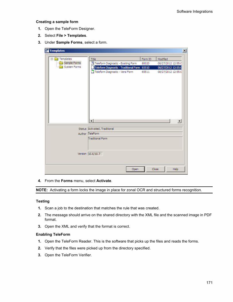
Software Integrations
171
Creating a sample form
1. Open the TeleForm Designer.
2. Select File > Templates.
3. Under Sample Forms, select a form.
4. From the Forms menu, select Activate.
NOTE: Activating a form locks the image in place for zonal OCR and structured forms recognition.
Testing
1. Scan a job to the destination that matches the rule that was created.
2. The message should arrive on the shared directory with the XML file and the scanned image in PDF format.
3. Open the XML and verify that the format is correct.
Enabling TeleForm
1. Open the TeleForm Reader. This is the software that picks up the files and reads the forms.
2. Verify that the files were picked up from the directory specified.
3. Open the TeleForm Verifier.

172
Software Integrations
If you do not see the new job, click the Refresh button.
NOTE: There is no time or date field by default. The only way to know this is your job is to look for any custom fields that may have been passed over with the job.
4. Highlight the job and click Process. This will open the job and display the scan.
Sending a form from TeleForm back to HPCR
You can set a form to feed back to a directory that the HPCR server is monitoring.
Configuring the form
1. Using the TeleForm Designer, open the form that will be used for scans:
a Select File > Templates > Sample Forms.
b Open the form you plan to use.
2. With the form open, select Form > Auto Export Setup.

Software Integrations
173
3. Click the New button and select Capture to Directory (VB.NET) from the drop-down in the Table Format field. This will capture an image file.
4. Click the File Export tab.

174
Software Integrations
5. Enable Export files and enter a directory that the HP CR XMLScan connector can access.
6. Repeat Steps 3 through 5 and select XML (C#) as the format. This will create an XML file.

Software Integrations
175
7. On the Fields tab, select the fields to export in the XML file.
8. Save the form when complete.
16-3-3 Enabling HP CR XMLScan
16-3-3-1 Creating an XMLScan connector
1. Click Start > All Programs > HP Capture and Route > HP Capture & Route Server Administrator to open the HP CR Server Administrator.
2. In the console tree, click Connectors > New HP Capture and Route Connector for > XmlScan. The Server Address page opens.
3. Click Next. Alternately, if you want the connector to run on a remote server, click Remote Server and enter the server name. Click Next. The Display Name page opens.
4. Enter a descriptive name and click Next. You are prompted to specify the folder to scan.
5. Click Browse and select the folder to scan.
6. Click Next. The connector is configured and added. The Congratulations page opens.
7. Click Finish.
The new XMLScan connector is listed in the details pane.

176
Software Integrations
16-3-3-2 Enabling XML translation
1. Click Start > All Programs > HP Capture and Route > HP Capture & Route Server Administrator to open the HP CR Server Administrator.
2. In the console tree, click Connectors. All connectors in the environment are listed in the details pan.
3. Double-click the XMLScan connector to open the Properties page.
4. Click Folders.
5. Select the folder that is listed and click Properties. The New Folder page opens.
6. Select the Enable XML Translation option and click Add. The Enter Extension page opens.
7. Enter:
*.xml
8. Click OK to close the page.
9. Click OK to save your changes and close the New Folder page.
Now you can copy the TeleformsIn.XSL file to the XMLScan folder:
1. Browse to:
C:\Program Files (x86)\HP\HPCR\Samples\XMLScan
2. Copy the file TeleformsIn.xsl to the folder specified for the XMLScan connector.

Part V:
Appendices


179
A Upgrading HP CR v1.1 to HP CR v1.2.0
Upgrading your current version of HP CR involves several steps, as detailed in this appendix:
Backing up the database (179)
Cancelling messages in the In Process queue (180)
Backing up the templates (180)
Uninstalling clients (180)
Uninstalling device clients from HP CR Server Administrator (181)
Deleting device clients and the Default group from the HP CR Server Administrator (181)
Uninstalling HP CR v1.1 clients from Programs and Features (181)
Running the server installation on the HP CR v1.1 system (182)
Installing clients (183)
Complete all of the procedures in this appendix in the order in which they are presented.
A-1 Backing up the databaseBefore you upgrade your current version of HP CR, you must back up the database. To back up and shrink the database:
1. Log in to the system that has the HP CR Server database.
2. Click Start > All Programs > Administrative Tools > Services.
3. Locate all HP Capture and Route services.
4. Right-click each service and click Properties from the drop-down menu.
5. On the Properties page, go to the Startup Type section and select Disabled from the drop-down menu.
6. Stop all HP Capture and Route services.
7. Using the Task manager, verify that all HP CR processes (beginning with Om*) are stopped.
8. Click Start > Run to open a Windows command prompt.
9. Back up the database using instructions provided by Microsoft in:
http://msdn.microsoft.com/en-us/library/ms130214(SQL.90).aspx
If necessary, change the name of the database while backing it up. You can also change the name of the backup file and the file path.
10. Locate the HP CR services and set the Startup Type to Automatic.
11. Start all HP CR services.

180
Upgrading HP CR v1.1 to HP CR v1.2.0
A-2 Cancelling messages in the In Process queueWhen preparing for the upgrade, you must wait for all messages to complete or cancel all messages in the In Process queue.
NOTE: Any message located in the In Process queue at the time of the upgrade fails to compose. This is indicated in the message journal.
You must also notify HP CR users that they cannot send documents and faxes until the server upgrade and
configuration is complete. It is recommended that you upgrade the server during off hours or when the volume of documents traffic is low.
A-3 Backing up the templatesThe setup program for the server upgrade overwrites all the files in these directories. Before you upgrade, you must back them up prior to running the server upgrade.
To backup your templates:
1. Make a backup copy of the Templates directory. The Templates directory is located in:
C:\Program Files (x86)\HP\HPCR\Languages\ENU\Notifications
where C: is the drive where the HP CR Server is installed.
NOTE: “ENU” in the path above is an example of a default language used by the system. Other supported languages are in separate directories. When navigating to the Templates directory, go to the Languages folder, select the language you use, and create a backup of the templates for that language.
2. Make a backup copy of the Embedded Directives directory. This directory is located in:
C:\Program Files (x86)\HP\HPCR\Languages\ENU\EmbeddedDirectives
where C: is the drive where the HP CR Server is installed.
NOTE: These directories contain cover page templates, Routing Sheet templates, and notification templates for your server.
A-4 Uninstalling clientsHP CR v1.2 requires that all previously installed client programs are uninstalled. To do so:
1. From Control Panel > Programs and Features, select Uninstall a program.
2. Continue to uninstall specific clients as described below.
Uninstalling Embedded Device Client for HP OXPd v1.4
1. Select the Embedded Device Client for HP OXPd v1.4.
2. Select Uninstall from the menu bar.
3. After uninstall is complete, verify that the OXP1.4 directory has been removed from:
C:\Program Files (x86)\HP location
4. Delete any folder that remains.

Upgrading HP CR v1.1 to HP CR v1.2.0
181
Uninstalling Embedded Device Client for HP OXPd v1.6
1. Select the Embedded Device Client for HP OXPd v1.6.
2. Select Uninstall from the menu bar.
3. After uninstall is complete, verify that the OXP1.6 directory has been removed from:
C:\Program Files (x86)\HP location
4. Delete any folder that remains.
Uninstalling HP Capture and Route Web Client
1. Select the HP Capture and Route Web Client.
2. Select Uninstall from the menu bar.
3. After uninstall is complete, verify that the Web Client directory has been removed from:
C:\Program Files (x86)\HP location
4. Delete any folder that remains.
A-5 Uninstalling device clients from HP CR Server Administrator
1. Launch the HP CR Server Administrator > Select Devices > Default. The list of installed devices appears in the results pane.
2. Right-click on the device and select Uninstall.
3. Repeat these steps for all installed device clients.
A-6 Deleting device clients and the Default group from the HP CR Server Administrator
1. Launch the HP CR Server Administrator > Select Devices > Default. The list of installed devices appears in the results pane.
2. Right-click on the device and select Delete.
3. Right-click on the Default group and select Delete.
A-7 Uninstalling HP CR v1.1 clients from Programs and Features
HP CR v1.2 requires that all previously installed client programs are uninstalled. To do so:
From Control Panel > Programs and Features, select Uninstall a program.
Continue to uninstall specific clients as described below.
Uninstalling Embedded Device Client for HP OXPd v1.4
1. Select the Embedded Device Client for HP OXPd v1.4.
2. Select Uninstall from the menu bar.

182
Upgrading HP CR v1.1 to HP CR v1.2.0
3. After uninstall is complete, verify that the OXP1.4 directory has been removed from:
C:\Program Files (x86)\HP\
4. Delete the OXP1.4 directory if it remains.
Uninstalling Embedded Device Client for HP OXPd v1.6
1. Select the Embedded Device Client for HP OXPd v1.6.
2. Select Uninstall from the menu bar.
3. After uninstall is complete, verify that the OXP1.6 directory has been removed from:
C:\Program Files (x86)\HP\
4. Delete the OXP1.6 directory if it remains.
Uninstalling HP Capture and Route Web Client
1. Select the HP Capture and Route Web Client.
2. Select Uninstall from the menu bar.
3. After uninstall is complete, verify that the Web Client directory has been removed from:
C:\Program Files (x86)\HP\
4. Delete the Web Client directory if it remains.
A-8 Running the server installation on the HP CR v1.1 system
To upgrade the server:
1. Close all applications on the server.
2. Navigate to the directory where you saved the download.
3. Run Setup.exe.
4. Click Next. The License Agreement page opens.
5. Read the license agreement. After scrolling to the bottom of the agreement, click the button beside the I Accept The Terms Of The License Agreement option.
6. Click Next. The setup checks the system for installation requirements and displays the results.
7. Review the results and click Next.
8. The setup requests logon credentials for the HP CR service account. Provide the logon credentials:
a In the NT Domain text box, enter the domain name.
b In the User Name text box, enter the user name.
c In the Password and Confirm Password text boxes, enter the password for the user.
9. Click Next. The Ready to Install page opens listing all the installation settings.
10. Review the installation settings. Click Next to begin the server upgrade.
The InstallShield Wizard upgrades the server. When upgrade is complete, you will see the InstallShield Wizard Complete page.
11. Click Finish to close the InstallShield wizard. The Server Configuration Wizard launches and shows the Welcome page.

Upgrading HP CR v1.1 to HP CR v1.2.0
183
12. Click Next. You are prompted to save the changes you made to the server configuration.
13. Click Finish.
The server configuration wizard saves your changes to the server configuration. The HP CR Server Administrator starts automatically.
A-9 Installing clientsRefer to Section 16 (157), the HP Capture and Route (HP CR) Embedded Device Client for HP OXPd Installation Guide, and the On-line help for the administrator for installation and troubleshooting procedures.

184
Upgrading HP CR v1.1 to HP CR v1.2.0

B Installing HP CR in a Non-English Environment
HP CR End User clients (devices, HP CR End User Interface, HP CR for HP OXPd 1.4 Client, HP CR for HP OXPd 1.6 Client, HP CR for Microsoft SharePoint, and HP CR for Autonomy WorkSite) have been localized for Simplified Chinese, French, German, Italian, Brazilian Portuguese, and Spanish. Installing HP CR in a non-English environment involves several steps, as detailed in this appendix:
Setting up a server before installing HP CR (185)
Installing HP CR (185)
Troubleshooting (186)
Standard device buttons have been localized. Note, however, that the Administrator can modify the text as it appears on a device button. These buttons will not appear as localized unless the Administrator enters the text in the applicable language.
B-1 Setting up a server before installing HP CRThrough the Windows Control Panel (Region and Language) on the HP CR server, set regional settings for the number format to US/UK.
This is necessary because, after the HP CR installation, a first-time wizard runs and attempts to create the default configuration (including implementing the default connectors). When the operating system that is set to non-US/UK regional settings, the numbering system often is altered to use commas as decimal points rather than periods. For example, in US regional settings, 100.00 is used to signify 100 with two decimal places. Throughout continental Europe, the value 100,00 (with a comma rather than a period). Use of the comma conflicts with HP CR saving certain data to the database (including while creating a connector).
B-2 Installing HP CRComplete the installation procedures in Section 3: Installing the HP CR server (27). Then, complete the configuration procedures in Section 4: HP CR post installation review and configurations (33).
B-2-1 Note about Routing Sheet templatesAfter installation, the HP CR server includes templates to allow for localization of each language that the server uses to process messages. The templates are located in the HPCR\Languages folder:
...\Program Files\HP\HPCR\Languages\ENU\Coverpages
When a Desktop Client (such as the End User Interface) contacts the server, it passes the local language to the HP CR server, which then uses the appropriate template based on the Client's language code. If the language code does not exist, it defaults to US English.
In the case of English (Ireland), for example, the language code ENI may be found in the language directory because it was manually created. But, HP CR does not automatically include a matching template in the HPCR\Languages folder. If you are setting up the HP CR server for English (Ireland), copy Routing Sheet templates from the ENU (US English) folder into the ENI folder.

186
Installing HP CR in a Non-English Environment
B-2-2 Application pool for the End User Interface must be changed when installing on a non-US operating system
1. Open Internet Information Services (IIS) Manager on the server where the End User Interface was installed.
2. Browse to Application Pools.
3. Select WebClient_Pool.
4. Select Advanced Settings on the Actions Pane.
5. Locate the Identity property under Process Model.
6. Click the ellipsis (...) next to NetworkService.
7. Select Custom account.
8. Click Set.
9. Enter the domain and user name of the HP CR Service Account (domain\username).
10. Enter the password.
11. Click OK on the Set Credentials page.
12. Click OK on the Application Pool Identity page.
13. Click OK to close the Advance Settings page.
14. Open the HP CR End User Interface to the test settings.
B-3 Troubleshooting
B-3-1 “Failed to save new object (0x80040e14)” messageThis message may display when installing HP CR v1.2 to a Windows operating system that is set to non-US/UK regional settings.
After the HP CR installation, a first-time wizard runs and attempts to create the default configuration, including implementing the default connectors. When the operating system that is set to non-US/UK regional settings, the numbering system often is altered to use commas as decimal points rather than periods. For example, in US regional settings, 100.00 is used to signify 100 with two decimal places. Throughout continental Europe, the value 100,00 (with a comma rather than a period).
Use of the comma conflicts with HP CR saving certain data to the database (including while creating a connector). A resolution is in development.
To work around this issue, set regional settings to US/UK on the HP CR server. These settings have been tested and confirmed to work.

Installing HP CR in a Non-English Environment
187
B-3-2 Installing in an environment without Microsoft Exchange or Lotus Notes causes logon issues for the End User Interface
After installing the HP CR End User Interface to an environment without Microsoft Exchange, the user may not be able to log in to the End User Interface. An LDAP warning is displayed. The End User Interface is attempting to look up attributes from Active Directory that are not available since the Active Directory Scheme was not modified (as it would be by installing Microsoft Exchange). This is addressable through a configuration change.
1. On the HP CR server, open Windows Explorer and browse to:
HP\HP CR\Config\AttributeMaps
2. Open the Exchange.default.xml file in Notepad (or an xml editor).
NOTE: Make a copy of Exchange.default.xml prior to changes.
3. The Exchange.default.xml file is set to read only. This option must be removed before any changes can be made.
4. In Exchange.default.xml, find the Exchange 2000 attributes section.
<!--Exchange 2000 attributes
--><Attribute>
5. Remove (cut) the trailing -->
The section should appear as:
<!--Exchange 2000 attributes<Attribute>
6. Paste the --> after the </Attribute> line in the file so that it looks like this:
<!--Exchange 2000 attributes<Attribute>
-->

188
Installing HP CR in a Non-English Environment