how to use this file(operators manuals) -...
TRANSCRIPT

How to use this file...(Operators Manuals)————————————————————————————————————————————–––
Instructions forPrint Vendors (Paper Manuals)
Paper Size: * 11 x 17* Body—50 lbs brilliant white offset or equivalent.* Cover—on pre-printed two-tone “Swash” stock.
Press : * Body—1-color, 2-sided* Cover imprint —1-color, 1-sided
Bindery : * Saddle Stitch, Face Trim* Face Trim
COVERS: * This file contains several manuals, which differ only in their covers.* Covers are all present at the beginning of this file.* Back cover for a particular manual is the page IMMEDIATELY AFTER the front cover.• Check the front cover for the individual part number (typically a 171xxxx number).
BODY: • The body of the manual is identical, regardless of the cover used.* REMEMBER: ODD number pages are ALWAYS right hand pages, and EVEN number are ALWAYS
left hand pages.
General : * This instruction page is NOT part of the manual and must NOT be printed.• Pages labeled with the text “THIS PAGE INTENTIONALLY BLANK” are placement pages ONLY,
and should NOT be printed.
————————————————————————————————————————————–––
If you have further questions on how to utilize this file, please contact Simplicity Technical Publications Department at ( 262) 284-8647.

THIS PAGE INTENTIONALLY BLANK

OPERATOR’SMANUAL
Sovereign Series18HP Hydro TractorsMfg. No. Description1692450 Sovereign, 18HP Hydro1692796 Sovereign, 18HP Hydro1692798 Sovereign, 18HP Hydro w/ PS1692889 Sovereign, 75th Anv. 18HP Hydro1692943 Sovereign, 18HP Hydro w/ PS1692945 Sovereign, 18HP Hydro1693144 Sovereign, 18HP Hydro1693146 Sovereign, 18HP Hydro w/ PS1693148 Sovereign, 75th Anv. 18HP (Ex.)1693407 Sovereign, 18HP Hydro w/ PS1693409 Sovereign, 18HP Hydro
48” Mower DecksMfg. No. Description1691219 48” Mower Deck1692890 48” Mower Deck, 75th Anv.1693173 48” Mower Deck (Export)1693418 48” Mower Deck
1715789-051714290-05
Rev 1/2002TP-100-2004-05-SV-S

MANUFACTURING, INC .500 N Spring Street / PO Box 997Port Washington, WI 53074-0997
www.simplicitymfg.com
© Copyright 2002 Simplicity Manufacturing, Inc.All Rights Reserved. Printed in USA.

OPERATOR’SMANUAL
900 Series18HP Hydro TractorsMfg. No. Description1692452 918H, 18HP Hydro1692845 918H, 18HP Hydro1692847 918H, 18HP Hydro w/ PS1692949 918H, 18HP Hydro w/ PS1692951 918H, 18HP Hydro1693411 918H, 18HP Hydro w/ PS1693413 918H, 18HP Hydro
48” Mower DecksMfg. No. Description1691221 48” Mower Deck1693419 48” Mower Deck
1717241-05, 1715790-051714299-05
Rev 1/2002TP-100-2004-05-SV-A

AGCO-Allis Lawn & Garden Equipment500 N. Spring Street \ P.O. Box 997Port Washington, WI 53074-0997 USA
www.allislawn.com
© Copyright 2002 Simplicity Manufacturing, Inc.All Rights Reserved. Printed in USA.

OPERATOR’SMANUAL
2800 Series
18HP Hydro TractorsMfg. No. Description1692503 2818H, 18HP Hydro1692849 2818H, 18HP Hydro1692852 2818H, 18HP Hydro w/ PS1692953 2818H, 18HP Hydro w/ PS1692955 2818H, 18HP Hydro1693415 2818H, 18HP Hydro w/ PS1693417 2818H, 18HP Hydro
48” Mower DecksMfg. No. Description1691221 48” Mower Deck1693419 48” Mower Deck
1715791-051714410-05
Rev 1/2002TP-100-2004-05-SV-M

Massey Ferguson Lawn & Garden Equipmentis Manufactured and Distributed by Simplicity Manufacturing, Inc.500 N. Spring Street • P.O. Box 997 • Port Washington, WI 53074-0997 USA
www.masseylawn.com
© Copyright 2002 Simplicity Manufacturing, Inc.All Rights Reserved. Printed in USA.

1
Table Of Contents
TRACTOR & MOWER IDENTIFICATION .....................2
SAFETY RULES ............................................................3
SAFETY DECALS .........................................................5
FEATURES & CONTROLS ...........................................6Tractor Controls ....................................................................6Safety Interlock System........................................................7
OPERATION ..................................................................8General .................................................................................8Checks Before Starting.........................................................8Clutch/Brake Pedal Operation ..............................................8Starting The Engine..............................................................8Stopping the Tractor .............................................................9Operation..............................................................................9Pushing the Tractor by Hand ...............................................9Mower Installation ..............................................................10Mower Removal..................................................................11
NORMAL CARE ..........................................................12Schedule.............................................................................12Raising the Hood ...............................................................12Checking/Adding Gasoline .................................................12Checking Tire Pressure ......................................................12Checking the Fuel Filter......................................................12Lubrication ..........................................................................13Checking Bevel Gear Box Fluid..........................................13Checking Transmission Fluid..............................................13Changing Transmission Fluid & Filter.................................14Battery Maintenance...........................................................15Servicing the Mower Blades ...............................................16
STORAGE ...................................................................17Temporary Storage.............................................................17
Long Term Storage.............................................................17
Starting After Storage .........................................................17
TROUBLESHOOTING & REPAIR...............................18General ...............................................................................18
Troubleshooting The Tractor ..............................................18
Troubleshooting The Mower...............................................19
Headlight Bulb Replacement ..............................................19
BATTERY SERVICE....................................................20Checking Battery Voltage ...................................................20
Charging A Completely Discharged Battery .......................20
Jump Starting with an Auxiliary Battery ..............................20
ADJUSTMENTS ..........................................................22Seat Adjustment .................................................................22
PTO Clutch Adjustment ......................................................22
Parking Brake Adjustment ..................................................22
Clutch/Brake Pedal Adjustment ..........................................23
Neutral Adjustment .............................................................23
Leveling the Mower ............................................................24
Blade Brake Adjustment .....................................................24
BELT REPLACEMENT................................................25Tractor Drive Belt................................................................25
Mower Belt..........................................................................25
SPECIFICATIONS .......................................................26
PARTS & ACCESSORIES ..........................................27Common Replacement Parts..............................................27
Maintenance Items .............................................................27
Optional Accessories..........................................................28
LAWN CARE & MOWING INFORMATION.................29
INTERNATIONAL SYMBOLS .....................................36
TECHNICAL MANUALS..............................................36
NOTE: In this manual, “left” and “right” are referred to as seenfrom the operating position.
WARNINGEngine exhaust from this product containschemicals known, in certain quantities, to causecancer, birth defects, or other reproductiveharm.
© Copyright 2002 Simplicity Manufacturing, Inc. All Rights Reserved. Printed In USA.
TP 100-2004-05-SV-SMA

2
Tractor & Mower Identification
Tractor Identification Tag
Mower Identification Tag169XXXX
MFG
Simplicity Manufacturing, Inc.Port Washington, WI 53074-0997 U.S.A.
SERIAL
XXXXX
SSAAMMPPLLEE
When contacting your AuthorizedDealer for replacement parts, service,or information YOU MUST HAVETHESE NUMBERS.
IDENTIFICATION NUMBERSRecord your model name/number, unit and mower deckmanufacturer numbers and engine serial number in thespace provided for easy reference.
• The Unit I.D. tag is located on the left-side, of theframe, as shown below.
• The Mower Deck I.D. tag is also on the left side, ontop of the mower deck.
• For location of Engine Serial Number, refer to theEngine Owner’s Manual.
Be sure to fill out and return the Warranty RegistrationCard supplied with your unit.
ENGINE REFERENCE DATA
Model Description Name/Number
Unit MFG Number
PRODUCT REFERENCE DATA
Unit SERIAL Number
Dealer Name Date Purchased
Engine Make
Engine Type/Spec
Engine Model
Engine Code/Serial Number
Mower Deck MFG Number Mower Deck SERIAL Number
IDENTIFICATION TAG LOCATIONS
Figure 1. Identification Tags
GENERAL OPERATION• Read, understand, and follow all instructions in the
manual and on the unit before starting.
• Only allow responsible adults, who are familiar withthe instructions, to operate the unit.
• Clear the area of objects such as rocks, toys, wire,etc., which could be picked up and thrown by theblade(s).
• Be sure the area is clear of other people before mow-ing. Stop unit if anyone enters the area.
• Never carry passengers.
• Do not mow in reverse unless absolutely necessary.Always look down and behind before and while trav-elling in reverse.
• Be aware of the mower discharge direction and donot point it at anyone. Do not operate the mowerwithout either the entire grass catcher or the deflectorin place.
• Slow down before turning.
• Never leave a running unit unattended. Alwaysdisengage the PTO, set parking brake, stop engine,and remove keys before dismounting.
• Turn off the PTO to disengage the blades when notmowing.
• Stop engine before removing grass catcher orunclogging chute.
• Mow only in daylight or good artificial light.
• Do not operate the unit while under the influence ofalcohol or drugs.
• Watch for traffic when operating near or crossingroadways.
• Use extra care when loading or unloading the unitinto a trailer or truck.
SLOPE OPERATIONSlopes are a major factor related to loss-of-control andtip-over accidents, which can result in severe injury ordeath. All slopes require extra caution. If you cannotback up the slope or if you feel uneasy on it, do not mow it.
Do• See your authorized dealer for recommendations of
wheel weights or counterweights to improve stability.
• Mow up and down slopes, not across.
• Remove obstacles such as rocks, tree limbs, etc.
• Watch for holes, ruts, or bumps. Uneven terrain couldoverturn the unit. Tall grass can hide obstacles.
• Use slow speed. Choose a low gear so that you willnot have to stop or shift while on the slope.
• Use extra care with grass catchers or other attach-ments. These can change the stability of the unit.
• Keep all movement on the slopes slow and gradual.Do not make sudden changes in speed or direction.
Do Not• Do not start or stop on a slope. If tires lose traction,
disengage the blade(s) and proceed slowly straightdown the slope.
• Do not turn on slopes unless necessary, and then,turn slowly and gradually downhill, if possible.
• Do not mow near drop-offs, ditches, or embank-ments. The mower could suddenly turn over if awheel is over the edge of a cliff or ditch, or if an edgecaves in.
• Do not mow on wet grass. Reduced traction couldcause sliding.
• Do not try to stabilize the unit by putting your foot onthe ground.
• Do not use grass catcher on steep slopes.
3
Safety Rules
Read these safety rules and follow them closely. Failure to obey these rules could result in loss of control ofrider, severe personal injury or death to you, or bystanders, or damage to property or equipment. Thismowing deck is capable of amputating hands and feet and throwing objects. The triangle in textsignifies important cautions or warnings which must be followed.
WARNING - SLOPE OPERATIONNever operate on slopes greater than 30 percent(16.7°) which is a rise of three feet vertically in 10 feethorizontally. When operating on slopes that aregreater than 15 percent (8.5°) but less than 30 percentuse front counterweights and rear wheel weights (seeyour dealer). Select slow ground speed before drivingonto slope. In addition to front and rear weights, useextra caution when operating on slopes with rear-mounted grass catcher. Mow UP and DOWN the slope,never across the face, use caution when changingdirections and DO NOT START OR STOP ON SLOPE.

4
CHILDRENTragic accidents can occur if the operator is not alert tothe presence of children. Children are often attracted tothe unit and the mowing activity. Never assume that chil-dren will remain where you last saw them.
• Keep children out of the mowing area and under thewatchful care of another responsible adult.
• Be alert and turn unit off if children enter the area.
• Before and when backing, look behind and down forsmall children.
• Never carry children. They may fall off and be seri-ously injured or interfere with safe unit operation.
• Never allow children to operate the unit.
• Use extra care when approaching blind corners, shrubs,trees, or other objects that may obscure vision.
TRANSPORTING AND STORAGE• Always observe safe refueling and fuel handling prac-
tices when refueling the tractor after transportation orstorage.
• Always follow the engine manual instructions forstorage preparations before storing the tractor forboth short and long term periods.
• Always follow the engine manual instructions forproper start-up procedures when returning the unit toservice.
• Never store the unit or fuel container inside wherethere is an open flame or pilot light, such as in awater heater. Allow unit to cool before storing.
Safety Rules
SERVICE AND MAINTENANCE• Use extra care in handling gasoline and other fuels.
They are flammable and vapors are explosive.
a) Use only an approved container.
b) Never remove gas cap or add fuel with the enginerunning. Allow engine to cool before refueling. Donot smoke.
c) Never refuel the unit indoors.
• Never run a unit inside an enclosed area.
• Keep nuts and bolts, especially blade attachmentbolts, tight and keep equipment in good condition.
• Never tamper with safety devices. Check their properoperation regularly.
• Keep unit free of grass, leaves, or other debris build-up. Clean up oil or fuel spillage.
• Stop and inspect the equipment if you strike anobject. Repair, if necessary, before restarting.
• Never make adjustments or repairs with the enginerunning unless specified otherwise in the enginemanufacturer’s manual.
• Grass catcher components are subject to wear, dam-age, and deterioration, which could expose movingparts or allow objects to be thrown. Frequently checkcomponents and replace with manufacturer’s recom-mended parts, when necessary.
• Mower blades are sharp and can cut. Wrap theblade(s) or wear gloves, and use extra caution whenservicing them.
• Check brake operation frequently. Adjust and serviceas required.
• Use only factory authorized replacement parts whenmaking repairs.
• Always comply with factory specifications on allsettings and adjustments.
• Only authorized service locations should be utilizedfor major service and repair requirements.
• Never attempt to make major repairs on this unitunless you have been properly trained. Improper ser-vice procedures can result in hazardous operation,equipment damage and voiding of manufacturer’swarranty.

5
Safety DecalsThis unit has been designed and manufactured to pro-vide you with the safety and reliability you would expectfrom an industry leader in outdoor power equipmentmanufacturing.
Although reading this manual and the safety instructionsit contains will provide you with the necessary basicknowledge to operate this equipment safely and effec-tively, we have placed several safety labels on the unit toremind you of this important information while you areoperating your tractor.
All WARNING, CAUTION and instructional messages onyour tractor and mower should be carefully read andobeyed. Personal bodily injury can result when theseinstructions are not followed. The information is for yoursafety and it is important! The safety decals shown beloware on your tractor and mower.
If any of these decals are lost or damaged, replace themat once. See your local dealer for replacements.
These labels are easily applied and will act as a constantvisual reminder to you, and others who may use theequipment, to follow the safety instructions necessary forsafe, effective operation.
Main Operation DecalPart No. 1716537
IgnitionSwitch
OFFRUN
START
Choke Lights
DO NOT TOW TRACTOR!Damage may result to transmission
ROTATING BLADESCUT OFF ARMSAND LEGSSTOP MOWER WHENCHILDREN ARE NEAR.
NO RIDERS— THEY FALL OFF.
DANGER
DANGEROPERATING ONSLOPES CAN BEDANGEROUSSEE OPERATOR'S MANUAL.IF YOU CANNOTBACK-UP A HILL—DO NOT DRIVE ON IT.
AVOID SERIOUS INJURY OR DEATHWARNING
Clutch / Brake Pedal
ENGAGECLUTCH
ENGAGEBRAKE
Parking BrakeLever
BRAKEON BRAKE
OFF
ENGAGE
CENTERDISENGAGE
PTO Clutch Lever
1716537
• READ OPERATOR'S MANUAL(S).• KNOW LOCATION AND FUNCTION OF ALL CONTROLS.• KEEP SAFETY DEVICES (GUARDS, SHIELDS, & SWITCHES) IN PLACE AND WORKING.• REMOVE OBJECTS THAT COULD BE THROWN BY THE BLADE.• DO NOT MOW WHEN CHILDREN OR OTHERS ARE AROUND.• NEVER CARRY CHILDREN.• LOOK DOWN AND BEHIND BEFORE AND WHILE BACKING.• AVOID SUDDEN TURNS.• IF YOU CANNOT BACK UP A HILL, DO NOT OPERATE ON IT.• GO UP AND DOWN SLOPES, NOT ACROSS.• IF MACHINE STOPS GOING UPHILL, STOP BLADE AND BACK DOWN SLOWLY.• BE SURE BLADE(S) AND ENGINE ARE STOPPED BEFORE PLACING HANDS OR FEET NEAR BLADE(S).• WHEN LEAVING MACHINE, SHUT OFF ENGINE, REMOVE KEY, AND SET PARKING BRAKE.
DISCONNECT GROUND – TERMINAL WHEN WORKINGON ELECTRICAL SYSTEMTO PREVENT SHORT CIRCUIT.
1716535
CAUTION
Disconnect Ground Caution DecalPart No. 1716535
1716
534
WARNINGTO AVOID INJURY
DO NOT RUN ENGINE WITH SEAT DECK RAISED.
Seat Raised Warning DecalPart No. 1716534
DANGER
ROTATING CUTTING BLADE Do not put hands or feet under mower deck while blade is rotating.
1704276
DANGER
ROTATING CUTTING BLADE Do not operate mower without deflector or entire grass catcher in place.
1704277
Decal - DangerPart No. 1704276
Decal - DangerPart No. 1704277

REF NAME FUNCTIONA Gasoline Gauge Shows gasoline level and serves as a tank cap
B Ammeter Shows when battery is being charged or discharged.
C Clutch/Brake Pedal Disengages clutch when depressed at least halfway. Applies brake when fully depressed.
D Ground Speed Control Lever Controls forward and reverse ground speeds.
E Ignition Switch & Key Starts and stops engine.
F Parking Brake Lever Locks brakes to hold tractor in parked position.
G PTO Lever Engages and disengages power to attachments.
H Choke Knob When pulled out, closes engine choke for cold weather starting. (Located on Dash on Power Steer Models)
I Light Switch Switches headlights on and off. (Located on Dash on Power Steer Models)
J Engine Speed Control Controls engine speed.
K Hydraulic Lift Lifts attachments to transport position.
L Hourmeter Optional accessory to record number of hours engine has run.
M Spout Rotator Optional accessory used to rotate spout on snowthrower.
6
TRACTOR CONTROLS
Features & Controls
Figure 2. Tractor Controls
*2240

7
Features & Controls*2293SAFETY INTERLOCK SYSTEM
Your tractor is equipped with a seat switch safety systemthat will automatically shut the engine off when the oper-ator leaves the seat with the ground speed control leverin gear or with the PTO engaged. Once the engine hasstopped, the electric PTO switch must be turned off afteroperator returns to the seat in order to start the engine.
Check the seat switch (A, figure 3) every fall and springwith the following four tests:
Test 1 - Engine should NOT crank if:A. seat is not occupied or
B. ground speed control lever out of neutral or
C. PTO lever is engaged.
Test 2 - Engine should crank if:A. seat is occupied and
B. ground speed control lever is in neutral and
C. PTO lever is disengaged.
Test 3 - Engine should shut off if:A. operator rises off seat with ground speed control
lever in gear.
B. operator rises off seat with PTO engaged.
NOTE: If operator returns to seat before engine stops,the engine will re-start and PTO clutch will re-engage.
Test 4 - PTO will disengage if:A. operator rises off seat with engine running.
NOTE: If operator returns to seat before engine stops,the engine will re-start and PTO clutch will re-engage.
Figure 3. Seat SwitchA. Switch B. Wiring Harness
WARNING
If the tractor does not pass the test, do not oper-ate tractor. See your authorized dealer. Under nocircumstances should you attempt to defeat thepurpose of the safety system.
A
B

8
Operation
GENERALBefore operating this tractor for the first time, the ownershould operate in an open area without mowing, tobecome accustomed to the unit. The right side of themower can be used to trim close to objects. Be sure toread all information in the Safety and Operation sectionsbefore attempting to operate this tractor and mower.
WARNINGNever allow passengers to ride on the unit.
WARNING
To reduce fire hazard, keep the engine andmower free of grass, leaves and excess grease.
WARNING
The interlock safety switches are for your safety.Do not attempt to bypass them.
CAUTION
Do not attempt to move the ground speed con-trol lever when the parking brake is engaged orthe service brakes are being applied. Equipmentdamage will occur.
CAUTION
Towing the tractor will cause transmission dam-age. Do not use another vehicle to push or pulltractor.
WARNING - SLOPE OPERATIONNever operate on slopes greater than 30 percent(16.7°) which is a rise of three feet vertically in 10 feethorizontally. When operating on slopes that aregreater than 15 percent (8.5°) but less than 30 percentuse front counterweights and rear wheel weights (seeyour dealer). Select slow ground speed before drivingonto slope. In addition to front and rear weights, useextra caution when operating on slopes with rear-mounted grass catcher. Mow UP and DOWN the slope,never across the face, use caution when changingdirections and DO NOT START OR STOP ON SLOPE.
CHECKS BEFORE STARTING1. Make sure you have proper wheel or counterweights
if required. See SLOPE OPERATION in the SafetyRules section. Make sure any slopes are withinrequired limits.
2. Check that crankcase is filled to full mark on dipstick.See the engine Operator’s Manual for instructionsand oil recommendations.
3. Make sure all nuts, bolts, screws and pins are inplace and tight.
4. Make sure you can reach all controls from operator’spositions. If not, see SEAT ADJUSTMENT.
5. Fill the gasoline tank with fresh gasoline. Fill to bot-tom of filler neck to avoid spillage and overflow. DONOT mix oil with gasoline. Refer to engine manualfor gasoline recommendations.
WARNING
Gasoline is highly flammable and must be han-dled with care. Never fill the tank when theengine is still hot from recent operation. Do notallow open flame, smoking or matches in thearea. Avoid over-filling and wipe up any spills.
CLUTCH/BRAKE PEDAL OPERATION1. See figure 6. Depressing the pedal from position A to
B disengages transmission drive belt and appliestractor brake.
2. To apply the parking brake pull up on the parkingbrake lever (F, figure 2).
STARTING THE ENGINERefer to figure 2.
1. Operator must be seated.
2. Place ground speed control lever (D) in neutral. Setparking brake. To set, depress pedal, pull parkingbrake lever (F) up, then release pedals.
3. PTO lever (G) must be in OFF position.
4. On a cold engine, pull out choke knob (H). On awarm engine, push choke knob in.
5. Place engine speed control (J) midway between slowand fast (Start/Stop position).
6. Turn key (E) to start engine. Push choke in as enginewarms up.
7. Allow engine to warm up for a couple of minutesbefore applying load. Do not idle engine for pro-longed periods or carbon buildup may occur.

9
Operation
STOPPING THE TRACTORRefer to figure 2.
1. Move ground speed control lever (D) to neutral anddepress brake pedal.
2. Switch PTO to off.
3. Move throttle midway between slow and fast positionbefore shutting off engine.
4. To set parking brake depress brake pedal and pullparking brake lever (F) up.
5. Push hydraulic lift lever forward to lower attachment.
6. Turn ignition off and remove key to prevent unautho-rized use.
WARNING
Before leaving operator’s position for any rea-son, engage the parking brake, disengage thePTO(s), stop the engine and remove the key.
WARNING
Do not tow the tractor. Damage will result to thetransmission/transaxle.
*2255
Figure 6. Clutch/Brake Pedal
*310
Figure 7. Transmission Release Lever
PUSHING THE TRACTOR BY HAND1. To push tractor by hand, the release lever (A, figure
7) must be engaged (pushed all the way down). Donot push the tractor with the engine running.
2. To drive the tractor, the release lever must be pulledall the way up.
OPERATION
Refer to figure 2.
1. Push parking brake lever down to release parkingbrake.
2. Move ground speed control lever (D) to forward orreverse to start into motion. The farther lever ismoved, the faster the ground speed. Place throttlelever in forward (fast) position.
3. Push the hydraulic lift lever (K) forward to lower theattachment. Pull lever back to raise the attachment.
4. Use the PTO lever (G) to engage or disengage theattachment.
WARNING
Make sure desired direction of travel is clear ofobjects, people and animals.

10
Operation
MOWER INSTALLATION
NOTE: Perform mower installation on a hard, level sur-face such as a concrete floor.
Refer to figure 4.
1. Park the tractor to the right of the mower and turn thetractor front wheels fully to the right.
2. Make sure the front idler pulley (L) is installed in topmounting tab for mower installation. Bottom mountingtab is used for snowthrower operation.
3. Start the engine. With ground speed control lever inNEUTRAL, release the clutch/brake pedal. Push thelift lever forward to lower the cable. Shut off theengine.
4. Reach under the tractor to grasp the lift cable andpull it straight down. The lift cable will not lower with-out weight on it.
WARNING
It will be necessary to start the engine to raise orlower the lift cable. Before starting the engine,always seat yourself in the operator’s position.Before leaving the operator’s position, stopengine and remove key. Do not engage PTO untilmower is completely installed and operator isseated.
Figure 4. Mower Installation & Removal
*2248
*2249
Figure 5. Mower Belt Adjustment
A. PTO Clutch Lever B. PTO Drive PulleyC. Belt Tensioning LeverD. Mower Drive BeltE. Lift AnchorF. Lift Cable ClevisG. DeflectorH. Mower Drive PulleyI. Mower Hitch ArmJ. Tractor Front HitchK. Lift LeverL. Front Idler PulleyM. Rear Idler Pulley

11
Operation
MOWER REMOVALNOTE: Perform mower removal on a hard, level surfacesuch as a concrete floor. Make sure there is room on theleft side of tractor to remove mower.
Refer to figure 4.
1. Push the belt tensioning lever (C) fully down and for-ward to release mower belt tension.
2. Raise the tractor seat deck and remove the mowerdrive belt from the mower and tractor pulleys. Closethe seat deck.
3. Use the tractor lift lever to raise the mower halfway.
4. Remove the safety clips and pins to detach themower hitch from the tractor hitch. Remove the right-hand side pin first. Reinstall the pins and safety clipsin the mower hitch for storage.
5. Lower mower fully.
6. Remove the spring clip and pin to detach the lift cablefrom the mower. Reinstall the pin and spring clip inthe lift cable for storage.
7. Turn tractor wheels fully right and slide the mower outthe left side.
8. Pull the belt tensioning lever fully back and up out ofthe way to prevent damaging it when using the tractorwithout the mower.
WARNING
It will be necessary to start the engine to raise orlower the lift cable. Before starting the engine,always seat yourself in the operator’s position.Before leaving the operator’s position, stopengine, remove key disengage power to attach-ments and set the parking brake.
5. Slide the mower under the tractor, then turn the frontwheels to face straight ahead. Use the lift cable pinand spring clip to attach the tractor lift cable clevis(F,) to the mower lift anchor (E). Use the lower holeon top lift cable clevis (not shown) for a higher trans-port position.
6. Start the engine and raise the mower halfway usingthe lift lever. Be sure to shut off tractor engine beforeleaving the seat.
7. Lift the front of the mower and attach the mower hitcharms (I) to the tractor hitch (J) using two pins andsafety clips. Install the pins from the outside. It is eas-ier to install the left-hand pin first.
8. Lower the mower fully using the lift lever.
9. Push the belt tensioning lever (C) fully down and for-ward.
10. Raise the tractor seat to gain access to the PTO pul-ley.
11. Install the mower drive belt on the mower pulley andtractor pulleys.The belt must be seated in the innergroove of the drive pulley (B). Make sure that flat sideof the belt contacts the front idler pulley (L).
12. Pull the belt tensioning lever (C) fully back and up toput tension on the mower drive belt.
13. When installing belt, the rear edge of the idler bracket(A, figure 5) should be aligned with the front edge ofthe green zone shown in figure 5. The distancebetween idler bracket (A) and stop (C) will be approx-imately 1-3/16” (30 mm).
14. Push the belt tensioning lever down to release belttension. Loosen the nut that secures the rear idlerpulley (D, figure 5) in the slot. To move the idlerbracket (A) forward, move rear idler pulley (D) rear-ward. Tighten the nut to secure pulley. Pull the belttensioning lever up and check position of idler brack-et (A). Readjust as necessary.
15. Operate the tractor with mower engaged for 15 - 30minutes with a new belt; about two minutes with aused belt. Disengage the PTO, stop the engine,remove the key, shift into neutral and set the parkingbrake. Check position of the idler bracket (A,figure 5).If the rear edge of the bracket is not aligned with frontedge of green zone, repeat step 14.
Check adjustment periodically. If rear edge of idlerbracket moves into red, repeat step 14.
16. If a new belt or mower was installed, level the moweras described in the Adjustments section.
NOTE: Check belt adjustment periodically during mowerseason. Drive belt must be readjusted when rear edge ofidler bracket aligns with rear edge of green zone or goesinto the red zone.

See Every Every EverySafety Items Page 5 Hours 25 Hours 100 Hours
*Or YearlyCheck safety interlock system. 7 �
Check tractor brakes. 24 �
Normal Care ItemsCheck tractor & mower for loose hardware. – �
Lubricate tractor and mower. - �
Check tires. 13 �
Oil Pivot points. 15 �
Check transmission fluid. 15 �
Change transmission fluid & filter. 16 Trans. service only or every 400 hours.
Check and clean battery. 16 �
Clean, sharpen and balance blades. 17 �
Clean and repack front wheel bearings. - �
See engine manual for engine care & maintenance.
RAISING THE HOODTo gain access to the engine compartment, release therubber strap on each side of the hood and raise thehood.
CHECKING/ADDING GASOLINECheck the gas gauge/cap to be sure there is enoughgasoline to complete the job. To add gasoline, removethe gas gauge/cap. Do not overfill. Leave room in thetank for fuel expansion. Refer to your engine manual forgasoline recommendations. Install and hand tighten thegas gauge/cap.
CHECKING TIRE PRESSUREFront tire pressure should be 12 to 15 psi (82 to 103 kPa).Rear tire pressure should be 6 to 8 psi (41 to 55 kPa).
CHECKING FUEL FILTER
The fuel filter is located in fuel line between fuel tank andcarburetor. If filter is dirty or clogged, replace as follows.Place a container below filter to catch spilled gasoline.
1. Using a pliers, open and slide hose clamps from fuelfilter.
2. Remove hoses from filter.
3. Install new filter in proper flow direction in fuel line.Secure with hose clamps. See warning at beginningof procedure.
SCHEDULEThe following schedule should be followed for normal care of your tractor and mower. You will need to keep a recordof your operating time.
CAUTION
Do not run the engine with the hood raised.Engine heat will cause damage to the headlightbezel and hood.
CAUTION
Never use gasoline containing METHANOL, gaso-hol containing more than 10% ethanol, gasolineadditives, premium gasoline, or white gas becauseengine/fuel system damage could result.
WARNING
Do not remove fuel filter when engine is hot, asspilled gasoline may ignite. DO NOT spread hoseclamps further than necessary. Ensure clampsgrip hoses firmly over filter after installation.
12
Normal Care

13
Normal Care
LUBRICATION
Tractor Lubrication Lubricate the tractor as shown in figures 8 -10. When agrease gun is shown, wipe the fitting clean, apply two orthree shots of lithium base automotive grease, and wipeoff excess grease. When an oil can is shown, wipe thearea clean, apply a few drops of oil (SAE 30), then wipeup drips or spills.
Mower Lubrication 1. Remove mower from tractor.
2. Remove cotter pins in order to lift the bail assembly.
3. See figure 11. Remove the taptite screws to removethe R.H. cover. Both covers can be removed tocheck/clean mower deck.
4. Apply a few drops of oil or one or two shots of grease(if equipped with grease fitting) to idler pulley pivot fit-ting and wipe off excess oil or grease. Do not get oilor grease on mower belt. Idler pulley pivot should belubricated yearly.
5. Install cover and taptite screws. Be sure the belt fitsinside of the belt guide which is located on bottom ofcover.
6. Install bail assembly and secure with cotter pins. Besure to spread cotter pins.
7. Lubricate the mower arbors as shown in figure 12.
CHECKING BEVEL GEAR BOX FLUID1. Remove the fill plug (A, figure 13) and wipe oil off
attached pin.
2. Insert the fill plug loosely in hole (do not screw it in).In this position, the fluid should just touch the bottomof the pin.
3. Add multi-purpose powertrain oil if required andinstall plug. Do not overfill.
4. To drain gear box, loosen the capscrews at the rearcover plate.
CHECKING TRANSMISSION FLUID1. Park the tractor on a flat, level surface.
2. Wipe the transmission fill cap (C, figure 14) and filltube (D) clean, then remove the cap.
3. Lift and hold the relief valve (E) open. Fluid should beat top of filler pipe. If not, add multi-purpose hydraulictransmission fluid oil. Relief valve must be held firmlyup when adding oil.
*2243
Figure 8. Clutch/Brake Pedal Grease Fitting
*2244
Figure 10. Steering Gear Grease Fitting
Figure 9. R.H. Rear Axle Grease Fittings (Two)
*2242

14
Normal Care
*313
Figure 11. Idler Pulley PivotA. Cover C. Bail AssemblyB. Taptite Screws D. Idler Pulley Pivot
Figure 12. Mower Arbor
*1606
Figure 13. Bevel Gear BoxA. Oil Fill/Check Plug B. Bevel Gear Box
*2245
Figure 14. Hydrostatic TransmissionA. Release Lever D. Fill TubeB. Cooling Fins E. Relief ValveC. Fill Cap F. Filter
*310
CHANGING TRANSMISSION FLUID & FILTERNOTE: The filter is shown in figure 14. Replace the filterevery 400 hours of operation or whenever changingtransmission fluid. Transmission fluid should be changedonly when performing repair work on transmission orhydrostatic unit, or if it becomes discolored from over-heating.
1. With hydrostatic transmission fluid hot, park tractoron a hard, level surface. Place ground speed controllever in neutral, place PTO lever in disengaged posi-tion, engage the parking brake and then stop theengine.
2. Press transmission release lever (A, figure 14) downfirmly to disengage the hydrostatic pump.
3. Remove hydrostatic transmission drain plug (B, figure15) from lower right-hand side. Remove dirt fromaround the fill cap (C, figure 14) and loosen cap topermit air to enter transmission.
4. Clean dirt from the transmission filter and filter holderinto which it is mounted. Remove and discard filter.

15
Normal Care
2. Remove the battery clamp, then remove the battery.
3. Scrub the battery, cables and battery compartmentwith baking soda and water.
4. Clean the battery terminals and cable clamps with awire brush and battery post terminal cleaner.
5. Reinstall battery and clamp.
6. Connect cables, positive cable first.
7. Coat cable clamps and terminals with grease orpetroleum jelly.
Figure 16. Battery CompartmentA. Positive Battery Terminal C. LocknutsB. Negative Battery Terminal D. Battery Clamp
*2247
Figure 15. Hydrostatic TransmissionA. Cooling Fan Screen B. Drain Plug
5. When fluid has drained out of transmission, installnew filter. Coat gasket on filter with transmissionfluid. Screw filter on until it contacts base, then tight-en 1/2 - 3/4 turn more. Do not use any tools to tightenfilter. Turn by hand only.
6. Install and tighten drain plug.
7. Remove the fill cap (C, figure 14) and clean dirt awayfrom relief valve (E). Using a clean funnel, add multi-purpose hydraulic transmission fluid into the fill tubewhile holding the relief valve up, until fill tube is full.Install fill tube and hand tighten.
8. Start engine and set it at idle speed, or slightly above.Let engine run at least five minutes, then stop engineand immediately lift relief valve and remove fill tubecap. While relief valve is up, pour more fluid into thefill tube until level reaches the “run over” point of thetube.
9. Install and tighten the fill tube cap. Be extremelycareful to keep all dust and dirt out of transmissionwhile changing oil and filter. Check filter and drainplug for leaks.
BATTERY MAINTENANCE
Checking the Battery Fluid
1. Raise the hood.
2. Remove battery filler cap. Fluid must be even with splitring full mark. If not, add distilled water.
3. Reinstall filler cap.
Cleaning the Battery and Cables
1. Disconnect the cables from the battery, negativecable first (B, figure 16).
WARNING
Be careful when handling the battery. Avoidspilling electrolyte. Keep flames and sparksaway from the battery.
WARNINGMake sure transmission release lever is firmlydown and that parking brake is engaged beforestarting the engine.
WARNING
When removing or installing battery cables, dis-connect the negative cable FIRST and reconnectit LAST. If not done in this order, the positive ter-minal can be shorted to the frame by a tool.
*2254

SERVICING THE MOWER BLADES1. Remove mower from the tractor.
2. Blades should be sharp and free of nicks and dents.If not, sharpen blades as described in following steps.
3. To remove blade for sharpening, use wooden blockto hold blade while removing the blade mounting cap-screw (figure 17).
4. Use a file to sharpen blade to fine edge. Remove allnicks and dents in blade edge. If blade is severelydamaged, it should be replaced.
5. Balance the blade as shown in figure 18. Center theblades’ hole on a nail lubricated with a drop of oil. Abalanced blade will remain level.
6. Reinstall each blade with the tabs pointing up towarddeck as shown in figure 19. Secure with a capscrew(D), cup washer (C) and spline washer (B). Use awooden block to prevent blade rotation and torquecapscrews to 45-55 ft.lbs. (61-75 Nm.).
16
LOOSEN
Figure 17. Removing The Blade
Figure 18 Balancing The Blade
Figure 19. Installing The BladeA. Wooden Block C. Cup WasherB. Spline Washer D. Capscrew
WARNING
For your personal safety, blade mounting cap-screws must each be installed with a cup washerand spline washer, then securely tightened.Torque blade mounting capscrew to 45-55 ft.lbs.(61-75 N.m.)WARNING
For your personal safety, do not handle thesharp mower blades with bare hands. Carelessor improper handling of blades may result inserious injury.
Normal Care
AD
CB
TIGHTEN
Thin Finishing Nail

17
Storage
WARNINGNever store the unit, with gasoline in engine orfuel tank, in a heated shelter or in enclosed,poorly ventilated enclosures. Gasoline fumes mayreach an open flame, spark or pilot light (such asa furnace, water heater, clothes dryer, etc.) andcause an explosion.
Handle gasoline carefully. It is highly flammableand careless use could result in serious firedamage to your person or property.
Drain fuel into an approved container outdoorsaway from open flame or sparks.
STORAGE
Temporary Storage (30 Days Or Less)Remember, the fuel tank will still contain some gasoline, sonever store the unit indoors or in any other area where fuelvapor could travel to any ignition source. Fuel vapor is alsotoxic if inhaled, so never store the unit in any structure usedfor human or animal habitation.
Here is a checklist of things to do when storing your unittemporarily or in between uses:
• Keep the unit in an area away from where children maycome into contact with it. If there’s any chance of unau-thorized use, disconnect the spark plug wires.
• If the unit can’t be stored on a reasonably level surface,chock the wheels.
• Clean all grass and dirt from the mower.
NOTE: If storing your tractor between winter snow removaljobs in a cold area, we suggest that you fill the fuel tank atthe completion of each job to prevent water condensation inthe fuel tank. Wait for engine to cool before filling tank.
Long Term Storage (Longer Than 30 Days)Before you store your unit for the off-season, read theMaintenance and Storage instructions in the Safety Rulessection, then perform the following steps:
1. Drain crankcase oil and refill with a grade of oil that willbe required when unit is used again.
2. Prepare the mower deck for storage as follows:
a. Remove mower deck from the unit.
b. Clean underside of mower deck.
c. Coat all bare metal surfaces with paint or light coat ofoil to prevent rusting.
3. Clean external surfaces and engine.
4. Prepare engine for storage. See engine owner’s manual.
5. Clean any dirt or grass from cylinder head cooling fins,engine housing and air cleaner element.
6. Cover air cleaner and exhaust outlet tightly with plasticor other waterproof material to keep out moisture, dirtand insects.
7. Completely grease and oil unit as outlined in the NormalCare section.
8. Clean up unit and apply paint or rust preventative to anyareas where paint is chipped or damaged.
9. Be sure the battery is filled to the proper level with waterand is fully charged. Battery life will be increased if it isremoved, put in a cool, dry place and fully charge aboutonce a month. If battery is left in unit, disconnect thenegative cable.
10. Drain fuel system completely or add a gasoline stabilizerto the fuel system. If you have chosen to use a fuel sta-bilizer and have not drained the fuel system, follow allsafety instructions and storage precautions in this man-ual to prevent the possibility of fire from the ignition ofgasoline fumes. Remember, gasoline fumes can travelto distant sources of ignition and ignite, causing risk ofexplosion and fire.
NOTE: Gasoline, if permitted to stand unused for extendedperiods (30 days or more), may develop gummy depositswhich can adversely affect the engine carburetor and causeengine malfunction. To avoid this condition, add a gasolinestabilizer to the fuel tank and run the engine a few minutes,or drain all fuel from the unit before placing it in storage.
STARTING AFTER LONG TERM STORAGEBefore starting the unit after it has been stored for a longperiod of time, perform the following steps.
1. Remove any blocks from under the unit.
2. Install the battery if it was removed.
3. Unplug the exhaust outlet and air cleaner.
4. Fill the fuel tank with fresh gasoline. See engine manual for recommendations.
5. See engine owner’s manual and follow all instructionsfor preparing engine after storage.
6. Check crankcase oil level and add proper oil if necessary. If any condensation has developed duringstorage, drain crankcase oil and refill.
7. Inflate tires to proper pressure. Check fluid levels.
8. Start the engine and let it run slowly. DO NOT run athigh speed immediately after starting. Be sure to runengine only outdoors or in well ventilated area.

GENERAL
This section of the manual provides troubleshooting andrepair instructions for the more common and easily corrected problems. For other problems, it is recom-mended that you contact your dealer.Locate the problemthat best describes the trouble that you have encoun-tered. Check the possible causes one at a time, in theorder that they are listed.
TROUBLESHOOTING THE TRACTOREngine will not turnover or start.1. Ground speed control lever not in neutral-start position.
Shift into neutral.
2. PTO lever in ON position. Place in OFF position.
3. Out of fuel. If engine is hot, allow it to cool, then refill thefuel tank.
4. Engine flooded. Push choke knob in.
5. Circuit breaker tripped. Wait one minute for automaticreset. Replace if defective (see your dealer).
6. Battery terminals require cleaning. See Normal Caresection.
7. Battery discharged or dead. Recharge or replace.
8. Wiring loose or broken. Visually check wiring & replacebroken or frayed wires. Tighten loose connections.
9. Solenoid or starter motor faulty. Repair or replace.
10. Safety interlock switch or module faulty. Replace ifneeded (see your dealer.)
11. Operator not in seat.
Engine cranks but will not start.1. Out of gasoline.
2. Engine flooded. Push in choke and attempt to start.Hold throttle wide open.
3. Crankcase oil too heavy. See engine manual.
4. Water in gasoline or gasoline is stale. Drain and fillwith fresh gasoline.
5. Faulty engine electrical or fuel system. See enginemanual or your dealer.
18
Troubleshooting & Repair
WARNING
To avoid serious injury, perform maintenance onthe tractor or mower only when the engine isstopped and the parking brake engaged. Alwaysremove the ignition key, disconnect spark plugwire and fasten away from the plug before begin-ning the maintenance, to prevent accidentalstarting of the engine.
Engine starts hard or runs poorly.1. Fuel mixture too rich. Clean air filter. Check choke
adjustment (engine speed control). See engine manual.
2. Carburetor adjusted incorrectly. See engine manual.
3. Spark plug(s) faulty, fouled, or incorrectly gapped.Clean and gap or replace. See engine manual.
4. In hot weather, fuel may evaporate from carburetorwhen engine is shut off, causing engine to run roughfor a few minutes after starting. Do not shut off; allowengine to clear itself.
5. Start engine with throttle midway between slow andfast.
Engine knocks.1. Low oil level. Check/add oil as required.
2. Using wrong grade oil. See engine manual.
3. Wrong grade of gasoline. Use fresh, regular grade ofgasoline.
Excessive oil consumption.1. Engine running too hot. Clean engine fins, blower
screen and air cleaner.
2. Using wrong weight oil. See engine manual.
3. Too much oil in crankcase. Drain excessive oil.
Engine exhaust is black.1. Dirty air filter. Clean air filter. See engine manual.
2. Check engine speed control adjustment (choke).See engine manual.
3. Carburetor adjustment is incorrect. See engine man-ual or your dealer.
Tractor creeps in neutral.1. Tractor creeps forward or backward with ground
speed control lever in neutral gate. Perform NeutralAdjustment.
Engine runs, but tractor will not drive orlacks power.1. Ground speed control lever in neutral. Shift in forward
or reverse.2. Transmission oil cold. Allow 3 minutes for warm-up.4. Transmission fluid low. Add as required. Check for
leaks.5. Transmission oil too hot. Check transmission cooling
fins for grass or clippings and clean with brush orcompressed air. Do not use water.
6. Belt is broken. See Drive Belt Replacement.7. Brake is not fully released. See Brake Adjustment.
19
Brake will not hold.1. Brake is incorrectly adjusted. See Brake Adjustment.
2. Brake lining worn. Replace.
Engine backfires when shut off.1. Engine backfire may occur when shut off hot. To
reduce backfiring, move throttle lever midwaybetween fast and slow for a couple seconds beforeshut off.
2. Carburetor solenoid not functioning. See your dealer.
TROUBLESHOOTING THE MOWER
Mower will not raise.1. Lift mechanism not attached or broken. Attach or
replace as necessary.
2. Hydraulic lift system faulty. See your dealer.
Mower cut is uneven.1. Mower not leveled properly. See Mower Adjustment.
2. Tractor tires not inflated equally or properly. SeeNormal Care.
3. Missing pin on mower hitch. Install pin.
Mower cut is rough looking.1. Engine speed too slow. Set for full throttle speed.
2. Ground speed too fast. Set ground speed controllever at a slower ground speed.
3. Blades dull and require sharpening. See Servicing theMower Blades.
4. Mower arbor belt slipping. Belt oily or worn. Clean orreplace belt as necessary.
5. Mower idler pulley pivot sticking. Check/lubricate asnecessary. See Normal Care.
5. Check PTO Adjustment. Clutch may need to beadjusted.
6. Blades not properly fastened to arbors or bent. SeeServicing the Mower Blades.
Engine stalls easily with mower engaged.1. Engine speed too slow. Set for 3/4 to full throttle.
2. Ground speed too fast.
3. Engine cold. Allow warm-up period.
4. Cutting height set too low when mowing tall grass.Cut tall grass at maximum cutting height during firstpass.
5. Discharge chute jamming with cut grass. Cut grasswith discharge pointing toward previously cut area.
Excessive mower vibration.1. Blade mounting screws are loose. Tighten to 50-70
ft.lbs. (74 Nm.).
2. Mower blades, arbors, or pulleys are bent. Check andreplace as necessary.
3. Mower blades are out of balance. Remove, sharpenand balance blades. See Servicing the MowerBlades.
Excessive belt breakage.1. Incorrect belt. Use belt designed for your mower.
2. Bent, loose or rough pulleys. Repair or replace.
3. Damaged mower pulley. See your dealer.
Mower drive belt slips or fails to drive.1. Pulleys or belt greasy or oily. Clean.
2. Belt stretched. Replace belt.
3. Mower idler pulley pivot sticking. Check/lubricate asnecessary.
Troubleshooting & Repair
HEADLIGHT BULB REPLACEMENT1. Disconnect the two wires from back of headlight.
Note position to reconnect to same terminals.
2. Turn socket to left to disconnect and pull out.
3. Replace the bulb.
4. Align the two tabs and insert socket. Turn to the rightto lock. Terminals will be at 12 o’clock and 6 o’clockpositions.
20
Troubleshooting & Repair
BATTERY SERVICE
Checking Battery VoltageA voltmeter can be used to determine condition of bat-tery. When engine is off, the voltmeter shows batteryvoltage, which should be 12 volts. When engine is run-ning, the voltmeter shows voltage of charging circuitwhich normally is 13 to 14 volts.
A dead battery or one too weak to start the engine maynot mean the battery needs to be replaced. For example,it may mean that the alternator is not charging the bat-tery properly. If there is any doubt about the cause of theproblem, see your dealer. If you need to replace the bat-tery, follow the steps under Cleaning the Battery &Cables in the Regular Maintenance Section.
Charging a Completely Discharged Battery1. Be aware of all the safety precautions you should
observe during the charging operation. If you areunfamiliar with the use of a battery charger andhydrometer, have the battery serviced by your dealer.
2. Add water sufficient to cover the plate (fill to the prop-er level near the end of the charge). If the battery isextremely cold, allow it to warm before adding waterbecause the water level will rise as it warms. Also, anextremely cold battery will not accept a normalcharge until it becomes warm.
3. Always unplug or turn the charger off before attach-ing or removing the clamp connections.
4. Carefully attach the clamps to the battery in properpolarity (usually red to [+] positive and black to [-]negative).
5. While charging, periodically measure the temperatureof the electrolyte. If the temperature exceeds 125° F(51.6° C), or if violent gassing or spewing of elec-trolyte occurs, the charging rate must be reduced ortemporarily halted to prevent battery damage.
WARNINGKeep open flames and sparks away from thebattery; the gasses coming from it are highlyexplosive. Ventilate the battery well duringcharging.
WARNINGDo not attempt to charge a frozen battery. Allowthe battery to warm to 60° F (15.5° C) beforeplacing on charger.
6. Charge the battery until fully charged (i.e. until thespecific gravity of the electrolyte is 1.250 or higherand the electrolyte temperature is at least 60° F). Thebest method of making certain a battery is fullycharged, but not over charged, is to measure thespecific gravity of a cell once per hour. The battery isfully charged when the cells are gassing freely at lowcharging rate and less than 0.003 change in specificgravity occurs over a three hour period.
Jump Starting With an Auxiliary (Booster) BatteryJump starting is not recommended. However, if it mustbe done, follow these directions. Both booster and dis-charged batteries should be treated carefully when usingjumper cables. Follow the steps below EXACTLY, beingcareful not to cause sparks. Refer to Figure 48.
1. Both batteries must be of the same voltage.
2. Position the vehicle with the booster battery adjacentto the vehicle with the discharged battery so thatbooster cables can be connected easily to the batter-ies in both vehicles. Make certain vehicles do nottouch each other.
3. Wear safety glasses and shield eyes and face frombatteries at all times. Be sure vent caps are tight.Place damp cloth over vent caps on both batteries.
4. Connect positive (+) cable to positive post of dis-charged battery (wired to starter or solenoid).
5. Connect the other end of same cable to same postmarked positive (+) on booster battery.
6. Connect the second cable negative (-) to other postof booster battery.
7. Make final connection on engine block of stalled vehi-cle away from battery. Do not lean over batteries.
8. Start the engine of the vehicle with the booster bat-tery. Wait a few minutes, then attempt to start theengine of the vehicle with the discharged battery.
9. If the vehicle does not start after cranking for thirtyseconds, STOP PROCEDURE. More than thirty sec-onds seldom starts the engine unless some mechani-cal adjustment is made.
10. After starting, allow the engine to return to idle speed.Remove the cable connection at the engine or frame.Then remove the other end of the same cable fromthe booster battery.
11. Remove the other cable by disconnecting at the dis-charged battery first and then disconnect the oppo-site end from the booster battery.
12. Discard the damp cloths that were placed over thebattery vent caps.

21
Troubleshooting & Repair
Figure 20. Jump Starting Diagram
WARNINGAny procedure other than the preceding couldresult in:
(1) personal injury caused by electrolytesquirting out the battery vents,
(2) personal injury or property damage due tobattery explosion,
(3) damage to the charging system of thebooster vehicle or of the immobilizedvehicle.
Do not attempt to jump start a vehicle having afrozen battery because the battery may rupture orexplode. If a frozen battery is suspected, examineall fill vents on the battery. If ice can be seen or ifthe electrolyte fluid cannot be seen, do notattempt to start with jumper cables as long as the
WARNINGFor your personal safety, use extreme care whenjump starting. Never expose battery to open flameor electric spark – battery action generateshydrogen gas which is flammable and explosive.Do not allow battery acid to contact skin, eyes,fabrics, or painted surfaces. Batteries contain asulfuric acid solution which can cause seriouspersonal injury or property damage.
When removing or installing battery cables, dis-connect the negative cable FIRST and reconnectit LAST. If not done in this order, the positive ter-minal can be shorted to the frame by a tool.
To avoid engine damage, do not disconnect bat-tery while engine is running. Be sure terminalconnections are tight before starting.
To StarterSwitch
StartingVehicleBattery
To Ground
To Starter Switch
DischargedVehicle Battery
EngineBlock
THIS HOOK-UP FOR NEGATIVE GROUND VEHICLES
MAKE CERTAIN VEHICLES DO NOT TOUCH
Jumper Cable
Jumper Cable

22
SEAT ADJUSTMENTSEAT-SLIDE EQUIPPED MODELSFor units equipped with a Seat Slide, See Figure 21. Usethe lever under the front of the seat to adjust the seatforward or rearward for best rider comfort.
STANDARD MODELS1. See Figure 22. Lift up the seat and loosen the four
capscrews.
2. Slide the seat forward or back and tighten the cap-screws.
PTO ADJUSTMENTSee Figure 23.
The PTO clutch is properly adjusted when the clutch pul-ley (C) moves away from clutch cone (D) 1/16” (1.5 mm)when clutch is disengaged. To adjust, proceed as fol-lows:
1. Loosen the rear nut (B).
2. Turn the front nut slightly clockwise to increase pulleytravel or counterclockwise to decrease pulley travel.
3. Tighten the rear nut against the front nut and checkthe measurement again.
4. Adjust locknut (E) so there is 1/8” (3 mm) betweenlocknut (E) and pivot arm when clutch is disengaged.
PARKING BRAKE ADJUSTMENTSee Figure 24.
1. Loosen jam nut (E) at parking brake rod end. Rotatethe parking brake handle (B) clockwise until it is tightand pulled up against fender as shown.
2. Operate the brake handle to see if it is too loose ortoo tight. It should be tight against fender when setbut not too tight to operate.
3. When proper adjustment is achieved, tighten jam nut.
NOTE: It will be easier to apply the parking brake whenthe clutch/brake pedal is fully engaged.
Adjustments
*2293
WARNING
To avoid serious injury, perform adjustmentsonly with engine stopped, key removed and trac-tor on level ground.
Figure 22 Seat Adjustment
*2252
Figure 23. PTO Clutch AdjustmentA. PTO Clutch Rod D. Clutch ConeB. Jam Nuts E. LocknutC. Clutch Pulley F. Pivot Arm
Capscrews
Springs
Capscrews
Figure 21 Seat Adjustment
1972_SVr1
Lever
23
Adjustments
**256
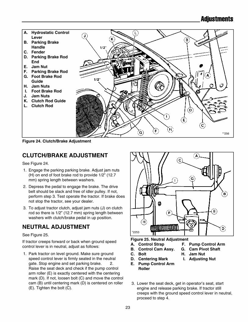
Figure 24. Clutch/Brake Adjustment
*2253
Figure 25. Neutral AdjustmentA. Control Strap F. Pump Control ArmB. Control Cam Assy. G. Cam Pivot ShaftC. Bolt H. Jam NutD. Centering Mark I. Adjusting NutE. Pump Control Arm
Roller
A. Hydrostatic ControlLever
B. Parking Brake Handle
C. FenderD. Parking Brake Rod
EndE. Jam NutF. Parking Brake RodG. Foot Brake Rod
GuideH. Jam NutsI. Foot Brake RodJ. Jam NutsK. Clutch Rod GuideL. Clutch Rod
CLUTCH/BRAKE ADJUSTMENTSee Figure 24.
1. Engage the parking parking brake. Adjust jam nuts(H) on end of foot brake rod to provide 1/2” (12.7mm) spring length between washers.
2. Depress the pedal to engage the brake. The drivebelt should be slack and free of idler pulley. If not,perform step 3. Test operate the tractor. If brake doesnot stop the tractor, see your dealer.
3. To adjust tractor clutch, adjust jam nuts (J) on clutchrod so there is 1/2” (12.7 mm) spring length betweenwashers with clutch/brake pedal in up position.
NEUTRAL ADJUSTMENTSee Figure 25.
If tractor creeps forward or back when ground speedcontrol lever is in neutral, adjust as follows:
1. Park tractor on level ground. Make sure groundspeed control lever is firmly seated in the neutralgate. Stop engine and set parking brake. 2.Raise the seat deck and check if the pump controlarm roller (E) is exactly centered with the centeringmark (D). If not, loosen bolt (C) and move the controlcam (B) until centering mark (D) is centered on roller(E). Tighten the bolt (C).
3. Lower the seat deck, get in operator’s seat, startengine and release parking brake. If tractor stillcreeps with the ground speed control lever in neutral,proceed to step 4.

24
Adjustments
Figure 26. Mower LevelingA. Height Adjustment HandleB. Jam NutC. YokeD. Height of Side BladesE. Side BladesF. Height of Center BladeG. Front Blade
4. Stop the engine, set the parking brake and raise theseat deck. Loosen the jam nut (H) on end of campivot shaft (G). If tractor creep had been in reverse,turn adjusting nut (I) 1/8 - 1/4 turn clockwise whenviewed from right side of tractor.
If tractor was creeping forward, turn nut 1/8 - 1/4 turncounterclockwise and lock jam nut
5. Lower seat deck and get in operator’s seat. Startengine and release parking brake. If tractor stillcreeps, repeat step 4, turning adjusting (I) until creep-ing stops.
LEVELING THE MOWERIf the cut is uneven, the mower may need leveling.Unequal or improper tire pressure may also cause anuneven cut. Make sure tire pressure is correct as speci-fied in Checking Tire Pressure.
See Figure 26.
1. Turn both height adjustment handles (A) fully clock-wise to the highest cutting height position.
2. Rotate the mower blades so the tips point straight for-ward and backward.
3. Measure and note the distance from the front tip ofthe center blade to the ground.
4. Measure the distances from the rear tips of the twooutside blades to the ground. They should be thesame. The rear measurement of the outside bladesshould be 1/8” - 1/4” (3 - 6 mm) less than the mea-surement for the front tip of the center blade. IF themeasurements are not correct, proceed to step 5.
5. Loosen the jam nuts (B). Remove the cotter pins andthen disconnect the eyebolts or yokes (C) from themower hitch.
6. Turning the eyebolts to change the length of the bailassembly arms. Shorten the arms to decrease thefront height of the mower; lengthen the arms toincrease the front height of the mower. Be sure toturn both yokes an equal number of turns for front-to-back leveling.
7. Reinstall the yokes on the hitch. It is not necessary toinstall the cotter pins yet. Check the blade tip mea-surements as described in steps 3 & 4. Continueadjusting the yokes until the front tip of the centerblade is 1/8” - 1/4” (3 - 6 mm) higher than the reartips of the side blades.
8. Reinstall the cotter pins securing the yokes to thehitch. Spread the cotter pin legs, then tighten the jamnuts (B).
BLADE BRAKE ADJUSTMENTMower blades and mower drive belt should come to acomplete stop within five seconds after front PTO isturned off.
1. With tractor in neutral, PTO disengaged and operatorin seat, start the tractor engine.
2. Look over the left-hand footrest at the mower drivebelt. Engage the PTO and wait several seconds.Disengage the PTO and check the amount of time ittakes for the mower drive belt to stop.
3. If mower drive belt does not stop within five seconds,perform the steps described under PTO ClutchAdjustment. Repeat steps 1 and 2. If belt still doesnot stop within 5 seconds, see your dealer.
WARNING
Before checking mower, shut off PTO andengine. Allow all moving parts to stop. Removeignition key, then disconnect the spark plug wireand fasten it away from the spark plug.

CAUTION
To avoid damaging belts, do not pry belts overpulleys.
25
Belt Replacement
TRACTOR DRIVE BELTSee Figure 27.
1. Park the tractor on a smooth, level surface such as aconcrete floor. Disengage the PTO, turn off theengine and lock the parking brake. Remove the key.
2. Tie the clutch/brake pedal down in the disengagedposition.
3. Raise the tractor seat deck. Remove the capscrew(C) and belt guard assembly (B).
4. Remove the two capscrews (D) and the taptite screw(E) in order to remove the fan guard assembly.
5. Remove the old belt and install the new one. Makesure the belt is in all pulley grooves and is not twist-ed.
6. Reinstall the fan guard with the capscrews (D) andthe taptite screw (E).
7. Release the clutch/brake pedal and check to be surebelt is still seated in all pulleys.
8. Reinstall the belt guard (B) so the bracket on theback side almost touches the pulley hub. Hold theguard in place and tighten the capscrew (B).
9. Check and adjust the tractor clutch according to theinstructions in the Adjustment section.
10. Lower and latch the seat deck when finished.
MOWER BELTSee Figure 28.
1. Set the parking brake, disengage the PTO, turn offengine and remove the key.
2. Remove mower from the tractor.
3. Lift the bail assembly (D) slightly to provide accessfor cover removal. Then lift the inner edge of theright-hand cover up over the lift anchor (F) and slide itout.
4. Clean the interior of the mower housing.
5. The idler pulley arm pivots at the lift anchor. Makesure the arm pivots freely. Lubricate the idler pivot fit-ting as necessary with a drop of oil. Do not get oil onthe mower belt.
Figure 27. Drive Belt ReplacementA. Belt D. Fan Guard ScrewsB. Belt Guard E. Taptite ScrewC. Capscrew
*2247
Figure 28. Mower BeltA. Idler Pulley D. Bail AssemblyB. Mower Belt E. Belt Covers C. Height Adjusting (Shown Removed)
Lever F. Lift Anchor
*2251
6. Unhook the idler spring (B) from the idler (A).Remove the old belt from the pulleys. Install the newbelt and attach the idler spring (B).
7. Install the belt covers and connect the bail assembly.When installing the right-hand belt cover, be sure thebelt is positioned in the belt guide which is located onthe bottom of the belt cover.

26
Specifications
ENGINE
18 HP Kohler OHCModel Kohler OHC Overhead Cam, TH18SHorsepower 18 HP @ 3600 rpmCylinders 2Bore 3.03 In. (77 mm)Stroke 2.64 In. (67 mm)Displacement 35 Cu. In. (574 cc)Construction Cast Iron Sleeves,
Aluminum CrankcaseElectrical 12 Volt, 15 Amp Alternator Regulated Battery:System 390 Cold Cranking Amps, 68 min. Reserve,
Industrial Rated Starter MotorIgnition Solid-State Inductive Electronic IgnitionGovernor Internal Flyweight with external AdjustmentAir Cleaner Dual ElementLubrication Full Pressure Lube with Oil FilterOil Capacity 3.5 Pints (1.7 L) without Filter
4 Pints (1.9 L) with Filter Fuel Tank Material: Non-Corrosive Polyethylene
Fuel Tank, Capacity: 3 Gallons (11.4 L)Muffler Quiet Compact, Low Back Pressure
18 HP KohlerModel Command OHVHorsepower 18 HP @ 3600 rpmCylinders 2Bore 3.03 In. (77 mm)Stroke 2.64 In. (67 mm)Displacement 38 Cu. In. (624 cc)Construction Cast Iron Sleeves,
Aluminum CrankcaseElectrical 12 Volt, 15 Amp Alternator Regulated Battery:System 296 Cold Cranking Amps, 60 min. Reserve
Capacity, Industrial Rated Starter MotorIgnition Electronic IgnitionGovernor Internal Flyweight with external AdjustmentAir Cleaner Dual ElementLubrication Full Pressure Lube with Oil FilterOil Capacity 2 Quarts (1.9 L)Fuel Tank Material: Non-Corrosive Polyethylene
Fuel Tank, Capacity: 3 Gallons (11.4 L)Muffler Quiet Compact, Low Back Pressure
DIMENSIONSOverall Length 70 In.(178 cm)Overall Width 36.9 In. (94 cm)Height To Top of Steering Wheel 39.7 In. (101 cm)Wheel Base 50.7 In. (127 cm)Weight (approx.)w/o mower 689 lbs.w/mower 956 lbs.
TRANSMISSIONType Hydrostatic Pump & Motor Air Cooled W/FanPump Variable Displacement Axial TypeMotor Fixed Displacement Reversible Axial TypeHydraulic Fluid Simplicity Multi-Purpose Hydro Transmission Oil
Reservoir: 3 Qt. Capacity (2.8 L)Filter: Cartridge w/25 Micron RatingFull Flow w/o Anti-Drain Back
Control Spring Dampened Single Lever Free Wheeling Valve for Manual Tractor Movement
Speeds Forward: 0 - 7 MPH (0 - 11.3 km/h)@3400 RPM Reverse: 0 - 4 MPH ( 0 - 6.4 km/h)Differential Planetary Spur Gear, Controlled Traction TypeFinal Drive Hardened Spur Gears
Rolling Contact Bearings
CONTROLSSteering Full Circle Steering Wheel
4.14 to 1 Ratio, Gear and SectorClutch/Brake Location Right Front; Clutch is soft action, V-belt
Clutch, Brake is external band typeLocation Implement Lift Lever: Left side (Hydraulic)
PTO Clutch Lever: Left sideGround Speed Control Lever: Right SideIgnition Key: On DashLight Switch: On DashThrottle Control: On Dash, Left SideChoke Control: On DashAmmeter: On DashParking Brake: Lower Right Side of Seat
CHASSISFrame Channel Electrically Welded Heavy Gauge Steel
Power Take-Off Points: Front , Center & Rear Engine Mounting Above Front AxlePivot Point Location: double Pivoting Heavy DutyCast Front Axle
Rear Wheels Tire Size 23 x 10.5-12 Pneumatic Inflation Pressure 6-8 psi (41-55 kPa)
Front Wheels Tire Size 16 x 6.50-8Pneumatic Inflation Pressure 12-15 psi (82-103 kPa)
Accessibility Hood Tips ForwardSeat Type Bucket, High Back, Adjustable w/
Spring Suspension
Turning Radius Inside Rear Tire 32 In. (81 cm)
NOTE: Specifications are correct at time of printing and are subject to change without notice.

27
Parts & Accessories
COMMON REPLACEMENT PARTSListed below are the more common replacement parts. Onlygenuine factory replacement parts will assure optimum perfor-mance and safety. Do not attempt repairs or maintenance unlessproper procedures and safety precautions are followed. Forassistance in any area, see your dealer.
QTY. DESCRIPTION PART NO.
3 Mower Blade (48” Mower) 16799161 Mower Belt (48” Mower) 16570441 Tractor PTO Belt 17135151 Oil Filter - Hydro Pump 17093221 Ignition Key Set 17140541 Battery 16850582 Mower Hitch Pins 1563062 Clips for Mower Pins 1760122 Headlamp Bulb 16773711 Clevis Pin - Lift Cable 1530581 Cotter Pin - Lift Cable 19184471 Spring Clip - Lift Cable 1918196
MAINTENANCE ITEMS• Simplicity Engine Oils
Case of 12 qts. (Your dealer has 1 qt. cans)-SAE 5W-30 SF/CD (Cold Weather 30° & under) 1685576-SAE 30W 3G/CC (Warm weather 32° & up) 1685659
• Simplicity Hydro Transmission OilCase of 12 qts. (Your dealer has 1 qt. cans) 1685516
• Touch-Up PaintDeep Orange Spray Paint, 13 oz. Can 1685611Deep Orange Paint, 1 qt. 1685612Black Spray Paint, 13 oz. Can 1685639Red Spray Paint, 13 oz. Can 1685722Metallic Gray, 13 oz. Can (Wheels) 1685718
• Touch-Up DaubersDeep Orange 1/2 oz. w/Brush Cap 1685615
• Grease Gun Kit w/8 oz. Grease Tube 1685510Replacement 8 oz. Grease Tube for above 103077
• Tire Sealant-Stops Tire Leaks. Prevents Flats.11 oz. Tube 1685523
• Gas Can-No Tip Design. Durable Polyethylene.1 gallon 16855872-1/2 gallon 16855555-1/4 gallon 1685556
• Cleaner, Polish, Sealant & Protectant8 oz. Bottle 1685696
• Degrimer/Degreaser32 oz. Bottle w/Trigger Spray 16856191 gallon 1685621
USE ONLY GENUINE
FACTORY REPLACEMENT PARTS
Available Through Your Local
Authorized Dealer

28
Parts & Accessories
OPTIONAL ACCESSORIESSee your dealer to purchase these items.
Dump Cart
36” & 42" Snowthrower
PTO Driven Vacuum Collector
38” Tiller
Tire Chains
Snow Cab
Wheel Weights