how to select a menu - bgu · how to select a menu there are two ways to select a menu. ......
TRANSCRIPT
1
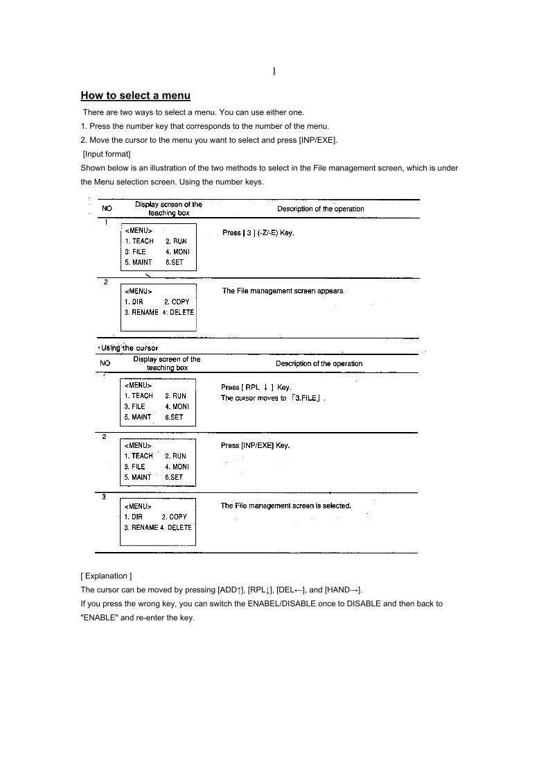
How to select a menu There are two ways to select a menu. You can use either one.
1. Press the number key that corresponds to the number of the menu.
2. Move the cursor to the menu you want to select and press [INP/EXE].
[Input format]
Shown below is an illustration of the two methods to select in the File management screen, which is under
the Menu selection screen. Using the number keys.
[ Explanation ]
The cursor can be moved by pressing [ADD↑], [RPL↓], [DEL←], and [HAND→].
If you press the wrong key, you can switch the ENABEL/DISABLE once to DISABLE and then back to
"ENABLE" and re-enter the key.
2
Programming with the teaching playback method
In this method, instead of using direct commands, you primarily use only the teaching box to do the
programming. By pressing certain keys on the teaching box, you can teach the robot a series of moves as
you actually take the robot along its work course in gradual order. One work operation is referred to as a
[step], a unit that refers to the movements to a certain taught point. There are two kinds of steps.
Table .Steps and a description of taught points
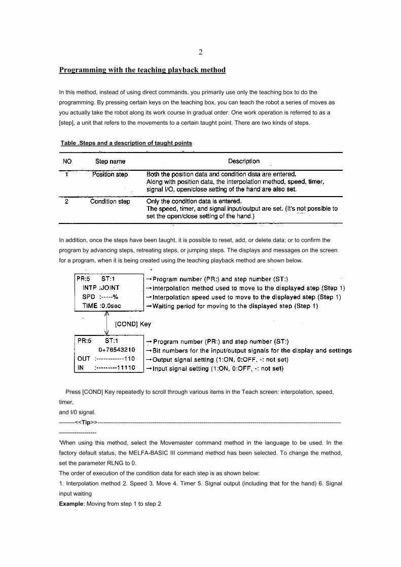
In addition, once the steps have been taught, it is possible to reset, add, or delete data; or to confirm the
program by advancing steps, retreating steps, or jumping steps. The displays and messages on the screen
for a program, when it is being created using the teaching playback method are shown below.
Press [COND] Key repeatedly to scroll through various items in the Teach screen: interpolation, speed,
timer,
and I/0 signal.
--------<<Tip>>----------------------------------------------------------------------------------------------------------------------------
-------------------
'When using this method, select the Movemaster command method in the language to be used. In the
factory default status, the MELFA-BASIC III command method has been selected. To change the method,
set the parameter RLNG to 0.
The order of execution of the condition data for each step is as shown below:
1. Interpolation method 2. Speed 3. Move 4. Timer 5. Signal output (including that for the hand) 6. Signal
input waiting
Example: Moving from step 1 to step 2
3
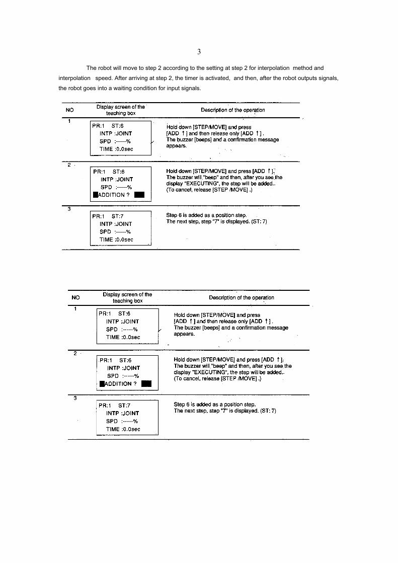
The robot will move to step 2 according to the setting at step 2 for interpolation method and
interpolation speed. After arriving at step 2, the timer is activated, and then, after the robot outputs signals,
the robot goes into a waiting condition for input signals.
4
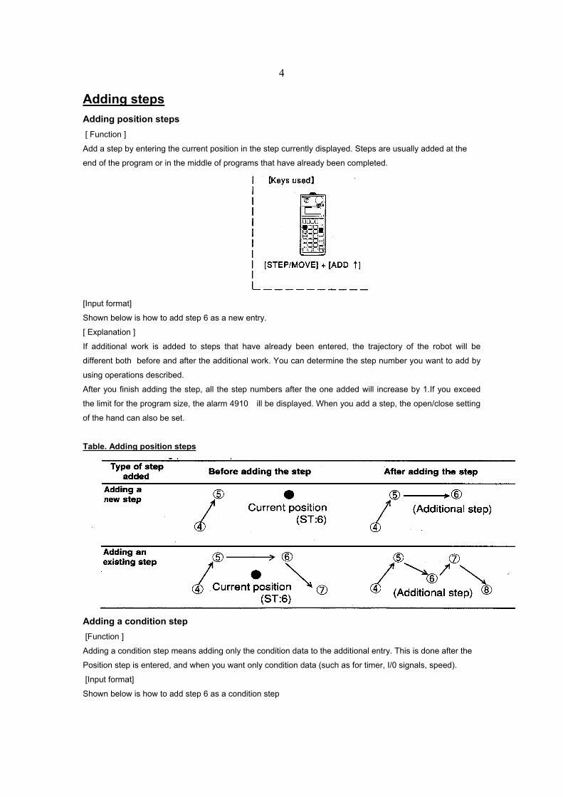
Adding steps Adding position steps [ Function ]
Add a step by entering the current position in the step currently displayed. Steps are usually added at the
end of the program or in the middle of programs that have already been completed.
[Input format]
Shown below is how to add step 6 as a new entry.
[ Explanation ]
If additional work is added to steps that have already been entered, the trajectory of the robot will be
different both before and after the additional work. You can determine the step number you want to add by
using operations described.
After you finish adding the step, all the step numbers after the one added will increase by 1.If you exceed
the limit for the program size, the alarm 4910 will be displayed. When you add a step, the open/close setting
of the hand can also be set.
Table. Adding position steps
Adding a condition step [Function ]
Adding a condition step means adding only the condition data to the additional entry. This is done after the
Position step is entered, and when you want only condition data (such as for timer, I/0 signals, speed).
[Input format]
Shown below is how to add step 6 as a condition step
5
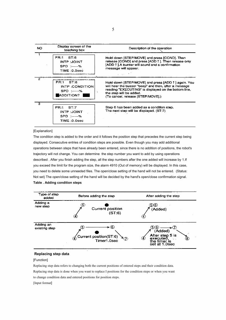
[Explanation]
The condition step is added to the order and it follows the position step that precedes the current step being
displayed. Consecutive entries of condition steps are possible. Even though you may add additional
operations between steps that have already been entered, since there is no addition of positions, the robot's
trajectory will not change. You can determine the step number you want to add by using operations
described . After you finish adding the step, all the step numbers after the one added will increase by 1.If
you exceed the limit for the program size, the alarm 4910 (Out of memory) will be displayed. In this case,
you need to delete some unneeded files. The open/close setting of the hand will not be entered. (Status:
Not set) The open/close setting of the hand will be decided by the hand's open/close confirmation signal.
Table . Adding condition steps
Replacing step data [Function]
Replacing step data refers to changing both the current positions of entered steps and their condition data.
Replacing step data is done when you want to replace I positions for the condition steps or when you want
to change condition data and entered positions for position steps.
[Input format]
6
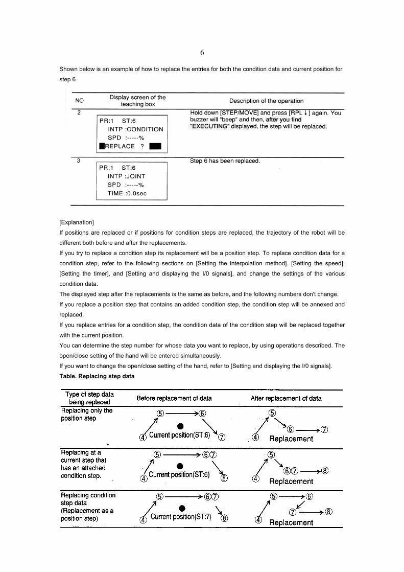
Shown below is an example of how to replace the entries for both the condition data and current position for
step 6.
[Explanation]
If positions are replaced or if positions for condition steps are replaced, the trajectory of the robot will be
different both before and after the replacements.
If you try to replace a condition step its replacement will be a position step. To replace condition data for a
condition step, refer to the following sections on [Setting the interpolation method]. [Setting the speed],
[Setting the timer], and [Setting and displaying the I/0 signals], and change the settings of the various
condition data.
The displayed step after the replacements is the same as before, and the following numbers don't change.
If you replace a position step that contains an added condition step, the condition step will be annexed and
replaced.
If you replace entries for a condition step, the condition data of the condition step will be replaced together
with the current position.
You can determine the step number for whose data you want to replace, by using operations described. The
open/close setting of the hand will be entered simultaneously.
If you want to change the open/close setting of the hand, refer to [Setting and displaying the I/0 signals].
Table. Replacing step data
7
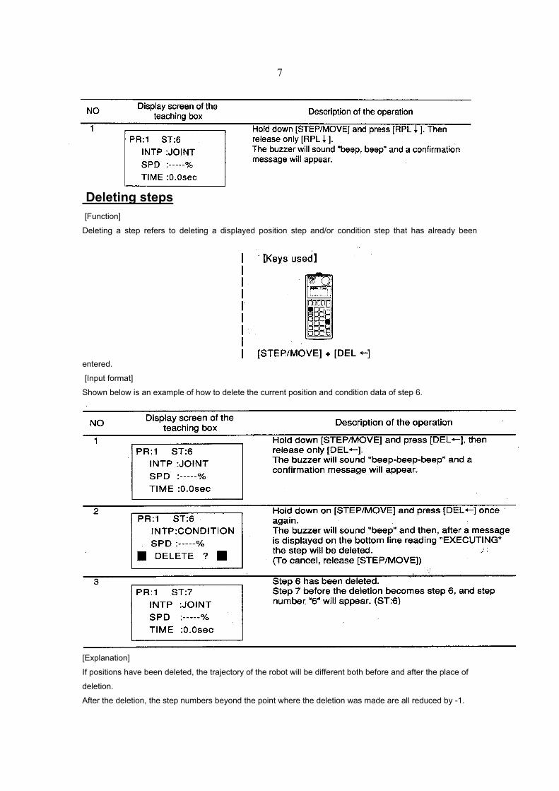
Deleting steps [Function]
Deleting a step refers to deleting a displayed position step and/or condition step that has already been
entered.
[Input format]
Shown below is an example of how to delete the current position and condition data of step 6.
[Explanation]
If positions have been deleted, the trajectory of the robot will be different both before and after the place of
deletion.
After the deletion, the step numbers beyond the point where the deletion was made are all reduced by -1.
8
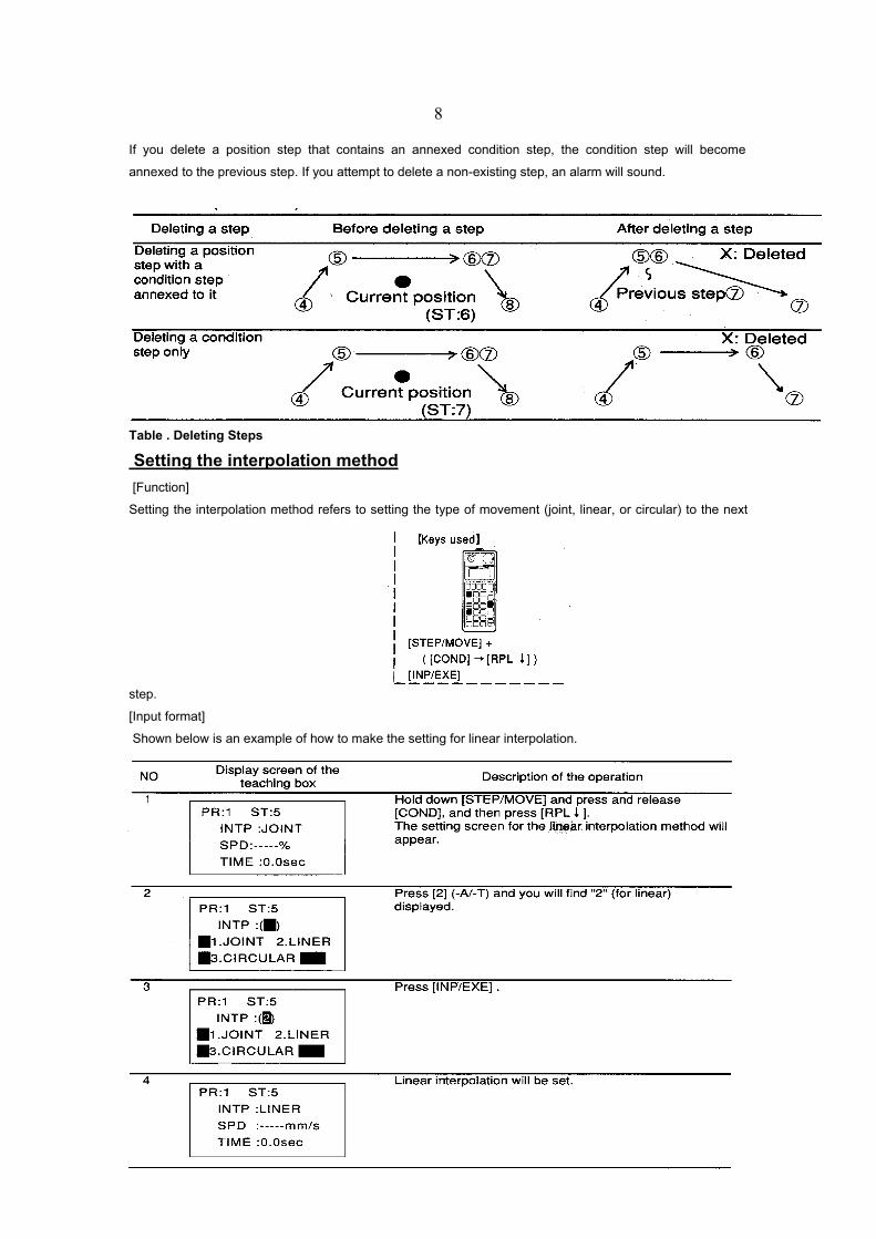
If you delete a position step that contains an annexed condition step, the condition step will become
annexed to the previous step. If you attempt to delete a non-existing step, an alarm will sound.
Table . Deleting Steps
Setting the interpolation method [Function]
Setting the interpolation method refers to setting the type of movement (joint, linear, or circular) to the next
step.
[Input format]
Shown below is an example of how to make the setting for linear interpolation.
9
[Explanation]
If you don't set the interpolation method the steps, they will use the interpolation method that was last used.
If the steps have never been set for the interpolation method, the joint interpolation method will be set.
When using joint interpolation or circular interpolation, depending on the setting for the speed and on the
posture of the robot, the maximum speed for the joints could be exceeded and cause an alarm. If this
happens, lower the setting for the speed. Press [COND] to display the teaching box screen. Also, each time
you press [COND], you can toggle between the interpolation/speed setting screen and the I/0 setting screen.
If there aren't at least 3 or more points for circular interpolation, the movement will be by linear interpolation.
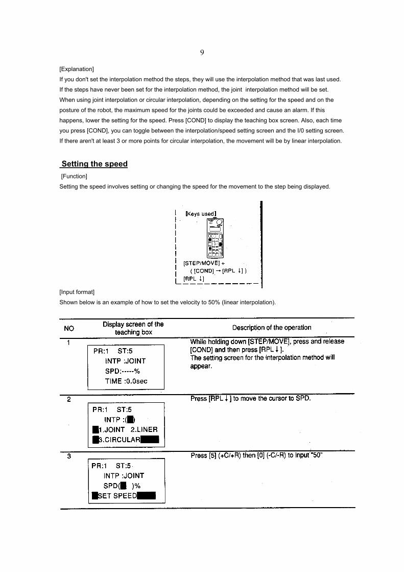
Setting the speed [Function]
Setting the speed involves setting or changing the speed for the movement to the step being displayed.
[Input format]
Shown below is an example of how to set the velocity to 50% (linear interpolation).
10
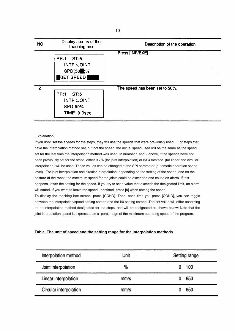
[Explanation]
If you don't set the speeds for the steps, they will use the speeds that were previously used. , For steps that
have the interpolation method set, but not the speed, the actual speed used will be the same as the speed
set for the last time the interpolation method was used. In number 1 and 2 above, if the speeds have not
been previously set for the steps, either 9.7% (for joint interpolation) or 63.3 mm/sec. (for linear and circular
interpolation) will be used. These values can be changed at the SPI parameter (automatic operation speed
level). For joint interpolation and circular interpolation, depending on the setting of the speed, and on the
posture of the robot, the maximum speed for the joints could be exceeded and cause an alarm. If this
happens, lower the setting for the speed. If you try to set a value that exceeds the designated limit, an alarm
will sound. If you want to leave the speed undefined, press [0] when setting the speed.
To display the teaching box screen, press [COND]. Then, each time you press [COND], you can toggle
between the interpolation/speed setting screen and the I/0 setting screen. The set value will differ according
to the interpolation method designated for the steps, and will be designated as shown below: Note that the
joint interpolation speed is expressed as a percentage of the maximum operating speed of the program.
Table .The unit of speed and the setting range for the interpolation methods
11
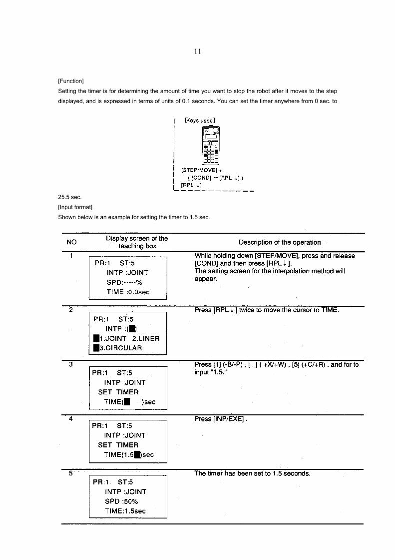
[Function]
Setting the timer is for determining the amount of time you want to stop the robot after it moves to the step
displayed, and is expressed in terms of units of 0.1 seconds. You can set the timer anywhere from 0 sec. to
25.5 sec.
[Input format]
Shown below is an example for setting the timer to 1.5 sec.
12
[Explanation]
The timer will be valid only for the step that was set. If nothing is set, "0" seconds will be used. If there is a
series of linear interpolation steps, and you don't want to set the timer, these steps will be treated as path
movement steps, and the robot will operate continuously, not accelerating nor decelerating along the way.
However, along the way, if there is a setting to wait for a signal input, the robot will stop temporarily. To
leave the timer setting so that it is not set, press [0] when setting the timer. To display the teaching box
screen, press [COND]. Then, each time you press [COND], you can toggle between the interpolation/speed
setting screen and the I/0 setting screen.
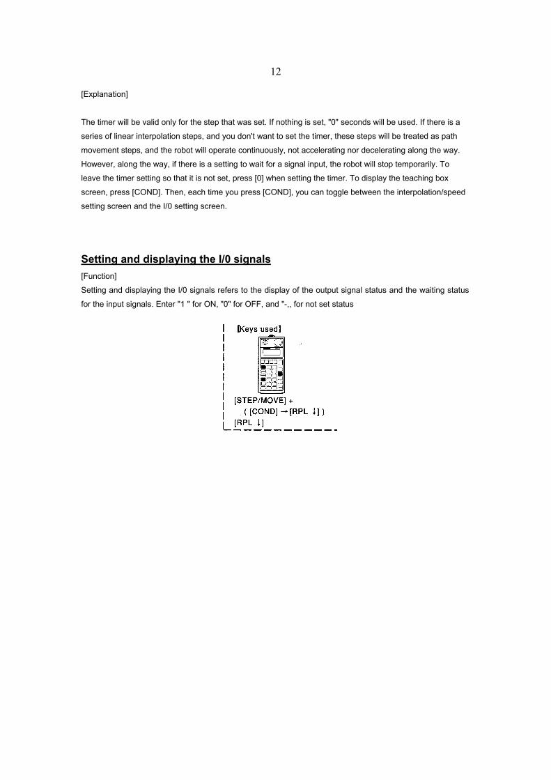
Setting and displaying the I/0 signals [Function]
Setting and displaying the I/0 signals refers to the display of the output signal status and the waiting status
for the input signals. Enter "1 " for ON, "0" for OFF, and "-,, for not set status
13
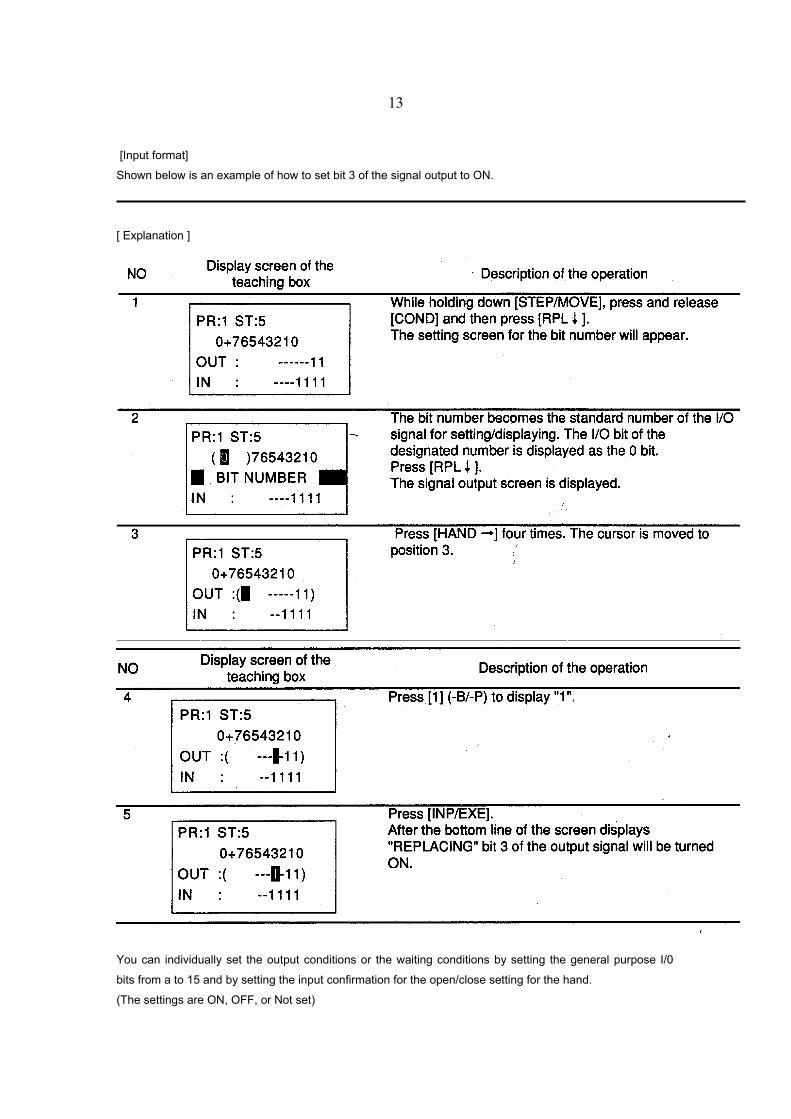
[Input format]
Shown below is an example of how to set bit 3 of the signal output to ON.
[ Explanation ]
You can individually set the output conditions or the waiting conditions by setting the general purpose I/0
bits from a to 15 and by setting the input confirmation for the open/close setting for the hand.
(The settings are ON, OFF, or Not set)
14
When steps are executed, if a plural number of bits is set for the signal output status, they will be output
simultaneously.
Once an output signal has been set, that same status will be maintained for all steps after that, until one is
reset (or changed).
Also, if not set, the steps will keep using the last output status.
If a plural number of bits are set for the input signal waiting condition, the robot will wait until all the
conditions are fulfilled. (For AND conditions) When waiting for multiple input bits
Under OR conditions, you need to change them beforehand into one input signal using the sequencer and
then input it.
The step setting for the input signal for the waiting condition is valid only for the step displayed.
When the timer has been previously set for a step, the timer is activated, then, after the output signal is sent,
the input signal waiting condition is executed. (Fixed order.)
If the hand's open/close setting set, ordinarily you would need to set the timer at the next step to wait for the
delay of the hand's movement.
Press [COND] to display the teaching box screen. Also, each time you press [COND], you can toggle
between the interpolation/speed setting screen and the I/0 setting screen.
To change the open/close setting of the hand, go to the Program editing screen and change the <0/C>
setting for the command "MPB."
By pressing [COND]+[ADD↑ ] on the teaching box, the Program editing screen can be displayed.
Manual Data Input (MOl) [Function]
MDI allows you to replace position data of a previously created program by keying in entries.
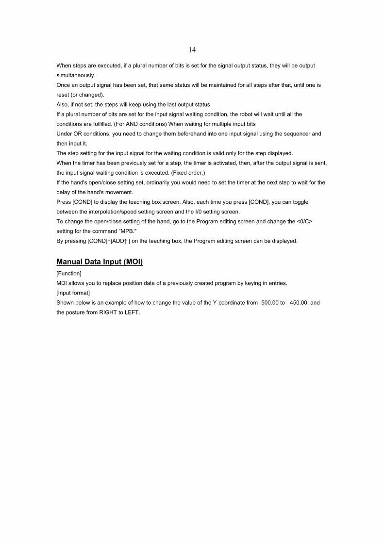
[Input format]
Shown below is an example of how to change the value of the Y-coordinate from -500.00 to - 450.00, and
the posture from RIGHT to LEFT.
15
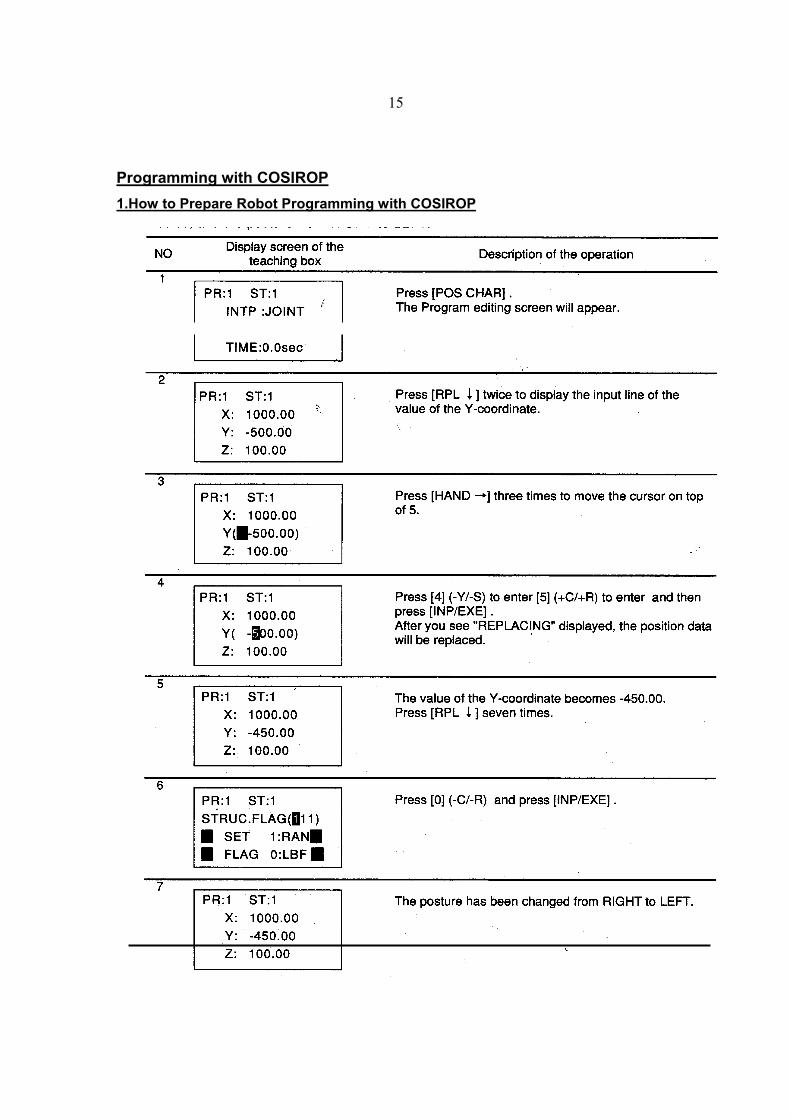
Programming with COSIROP 1.How to Prepare Robot Programming with COSIROP
16
Read and observe the safety instructions of the SAFETY MANUAL carefully before operating or programming the robot with COSIROP!
Before you can write robot programs and position lists with COSIROP you have to define your robot type
and configuration by Creating a Project.
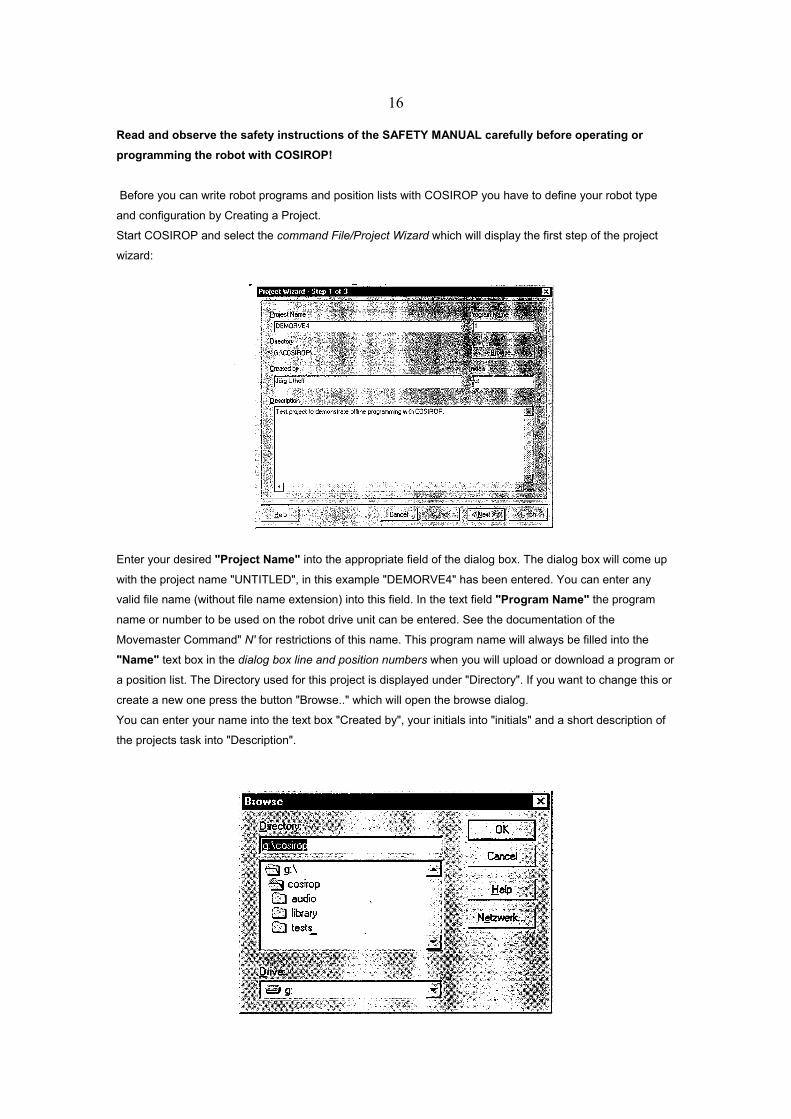
Start COSIROP and select the command File/Project Wizard which will display the first step of the project
wizard:
Enter your desired "Project Name" into the appropriate field of the dialog box. The dialog box will come up
with the project name "UNTITLED", in this example "DEMORVE4" has been entered. You can enter any
valid file name (without file name extension) into this field. In the text field "Program Name" the program
name or number to be used on the robot drive unit can be entered. See the documentation of the
Movemaster Command" N' for restrictions of this name. This program name will always be filled into the
"Name" text box in the dialog box line and position numbers when you will upload or download a program or
a position list. The Directory used for this project is displayed under "Directory". If you want to change this or
create a new one press the button "Browse.." which will open the browse dialog.
You can enter your name into the text box "Created by", your initials into "initials" and a short description of
the projects task into "Description".
17
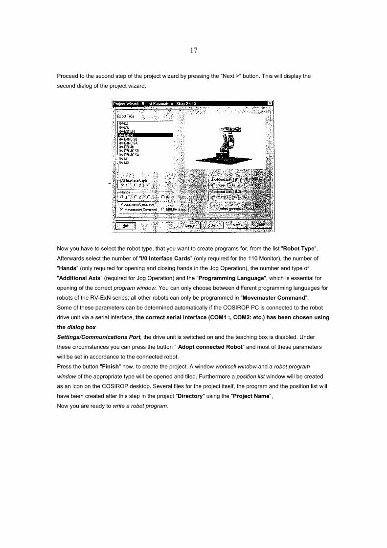
Proceed to the second step of the project wizard by pressing the "Next >" button. This will display the
second dialog of the project wizard.
Now you have to select the robot type, that you want to create programs for, from the list "Robot Type".
Afterwards select the number of "I/0 Interface Cards" (only required for the 110 Monitor), the number of
"Hands" (only required for opening and closing hands in the Jog Operation), the number and type of
"Additional Axis" (required for Jog Operation) and the "Programming Language", which is essential for
opening of the correct program window. You can only choose between different programming languages for
robots of the RV-ExN series; all other robots can only be programmed in "Movemaster Command".
Some of these parameters can be determined automatically if the COSIROP PC is connected to the robot
drive unit via a serial interface, the correct serial interface (COM1 :, COM2: etc.) has been chosen using the dialog box Settings/Communications Port, the drive unit is switched on and the teaching box is disabled. Under
these circumstances you can press the button " Adopt connected Robot" and most of these parameters
will be set in accordance to the connected robot.
Press the button "Finish" now, to create the project. A window workcell window and a robot program
window of the appropriate type will be opened and tiled. Furthermore a position list window will be created
as an icon on the COSIROP desktop. Several files for the project itself, the program and the position list will
have been created after this step in the project "Directory" using the "Project Name",
Now you are ready to write a robot program.
18
2. How to Establish a Connection to the Robot Drive Unit
Before you can exchange programs and position lists between the COSIROP PC and the robot drive unit the
following steps have to be executed.
1. Connect a serial interface (communications port) of the COSIROP PC to the RS-232 interface of the
robot drive unit. Be sure to use a cable that connects the hardware handshake signals (DTR, RTS,
CTS) of the serial interface, too.
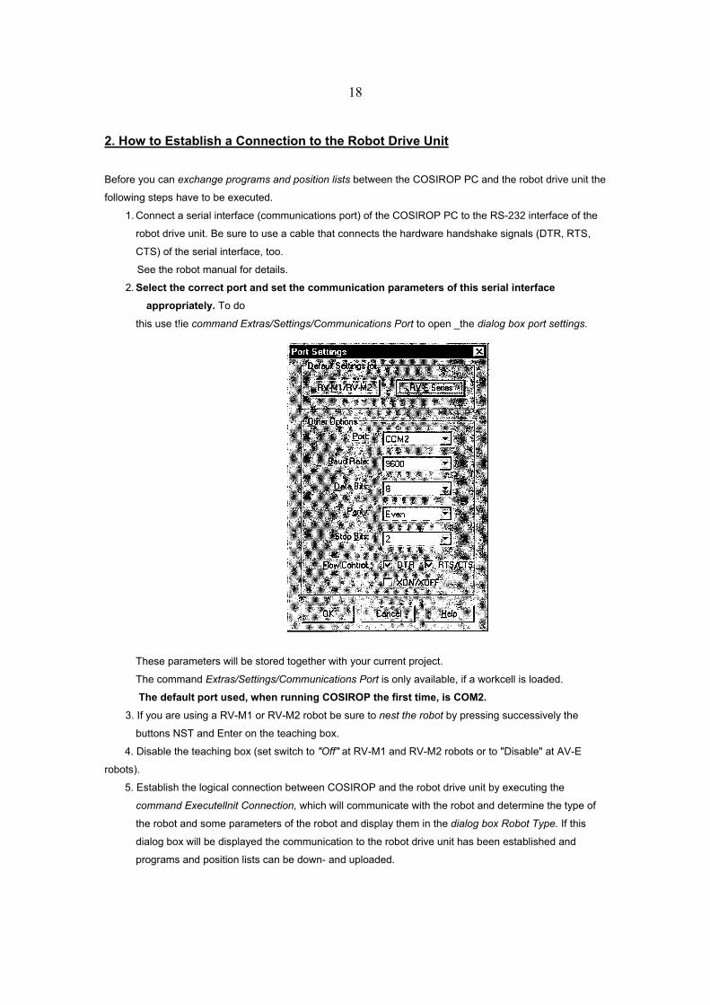
See the robot manual for details. 2. Select the correct port and set the communication parameters of this serial interface
appropriately. To do
this use t!ie command Extras/Settings/Communications Port to open _the dialog box port settings.
These parameters will be stored together with your current project.
The command Extras/Settings/Communications Port is only available, if a workcell is loaded.
The default port used, when running COSIROP the first time, is COM2. 3. If you are using a RV-M1 or RV-M2 robot be sure to nest the robot by pressing successively the
buttons NST and Enter on the teaching box.
4. Disable the teaching box (set switch to "Off" at RV-M1 and RV-M2 robots or to "Disable" at AV-E
robots).
5. Establish the logical connection between COSIROP and the robot drive unit by executing the
command Executellnit Connection, which will communicate with the robot and determine the type of
the robot and some parameters of the robot and display them in the dialog box Robot Type. If this
dialog box will be displayed the communication to the robot drive unit has been established and
programs and position lists can be down- and uploaded.
19
3. How to Write a Robot Program
After you have created a project you can write robot programs. Activate the window with the robot program
by clicking into the window or by selecting the window with the command Window/1,2,3… Now can freely
edit your program using the keyboard and the mouse.
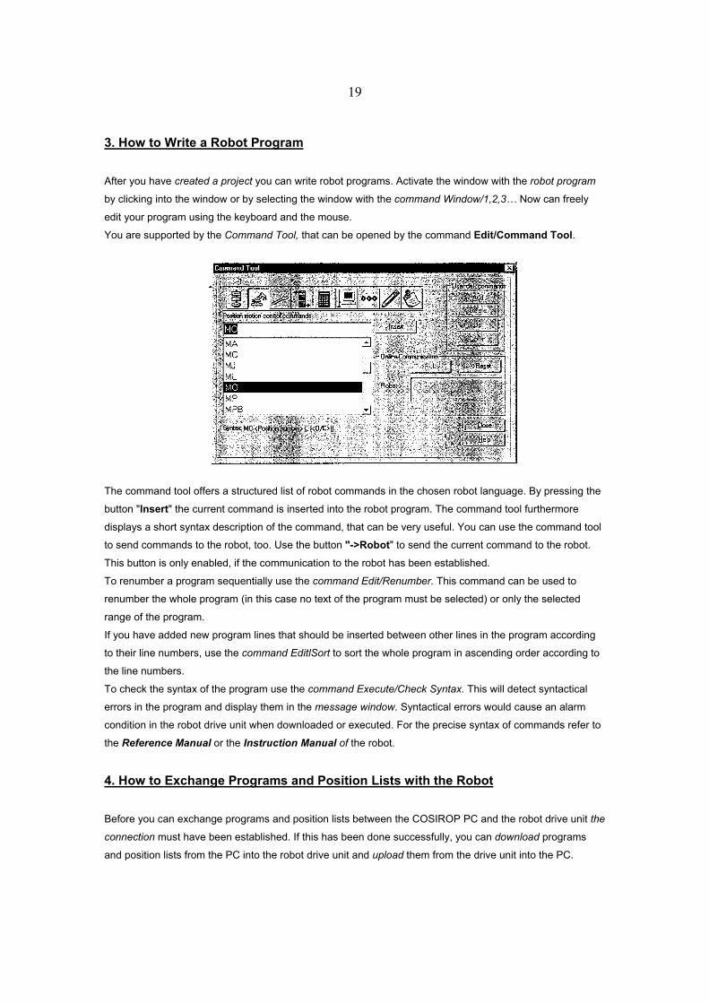
You are supported by the Command Tool, that can be opened by the command Edit/Command Tool.
The command tool offers a structured list of robot commands in the chosen robot language. By pressing the
button "Insert" the current command is inserted into the robot program. The command tool furthermore
displays a short syntax description of the command, that can be very useful. You can use the command tool
to send commands to the robot, too. Use the button "->Robot" to send the current command to the robot.
This button is only enabled, if the communication to the robot has been established.
To renumber a program sequentially use the command Edit/Renumber. This command can be used to
renumber the whole program (in this case no text of the program must be selected) or only the selected
range of the program.
If you have added new program lines that should be inserted between other lines in the program according
to their line numbers, use the command EditlSort to sort the whole program in ascending order according to
the line numbers.
To check the syntax of the program use the command Execute/Check Syntax. This will detect syntactical
errors in the program and display them in the message window. Syntactical errors would cause an alarm
condition in the robot drive unit when downloaded or executed. For the precise syntax of commands refer to
the Reference Manual or the Instruction Manual of the robot.
4. How to Exchange Programs and Position Lists with the Robot
Before you can exchange programs and position lists between the COSIROP PC and the robot drive unit the
connection must have been established. If this has been done successfully, you can download programs
and position lists from the PC into the robot drive unit and upload them from the drive unit into the PC.
20
4.1 Downloading a program
Activate the window with the robot program by clicking into the window or by selecting the window with the
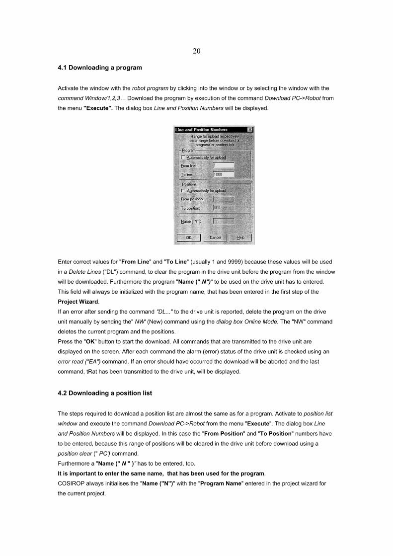
command Window/1,2,3… Download the program by execution of the command Download PC->Robot from
the menu "Execute". The dialog box Line and Position Numbers will be displayed.
Enter correct values for "From Line" and "To Line" (usually 1 and 9999) because these values will be used
in a Delete Lines ("DL") command, to clear the program in the drive unit before the program from the window
will be downloaded. Furthermore the program "Name (" N")" to be used on the drive unit has to entered.
This field will always be initialized with the program name, that has been entered in the first step of the
Project Wizard.
If an error after sending the command "DL..." to the drive unit is reported, delete the program on the drive
unit manually by sending the" NW' (New) command using the dialog box Online Mode. The "NW" command
deletes the current program and the positions.
Press the "OK" button to start the download. All commands that are transmitted to the drive unit are
displayed on the screen. After each command the alarm (error) status of the drive unit is checked using an
error read ("EA") command. If an error should have occurred the download will be aborted and the last
command, tRat has been transmitted to the drive unit, will be displayed.
4.2 Downloading a position list
The steps required to download a position list are almost the same as for a program. Activate to position list
window and execute the command Download PC->Robot from the menu "Execute". The dialog box Line
and Position Numbers will be displayed. In this case the "From Position" and "To Position" numbers have
to be entered, because this range of positions will be cleared in the drive unit before download using a
position clear (" PC') command.
Furthermore a "Name (" N " )" has to be entered, too.
It is important to enter the same name, that has been used for the program.
COSIROP always initialises the "Name ("N")" with the "Program Name" entered in the project wizard for
the current project.
21
4.3 Uploading a program
The procedure for uploading is very similar to the downloading procedure. Activate the program window that
shall be used for the uploaded program. You can open a new program window with the command File/New.
Then execute the command Upload Robot->PC from the menu "Execute". This will again open the dialog
box Line and Position Numbers where you should select "Automatically for Upload" in the "Program"
group box. After clicking the "OK" button the program will be uploaded line by line from the drive unit and
finally displayed in the program window.
During this upload the original program file on the disk will be overwritten and there is no way to restore it.
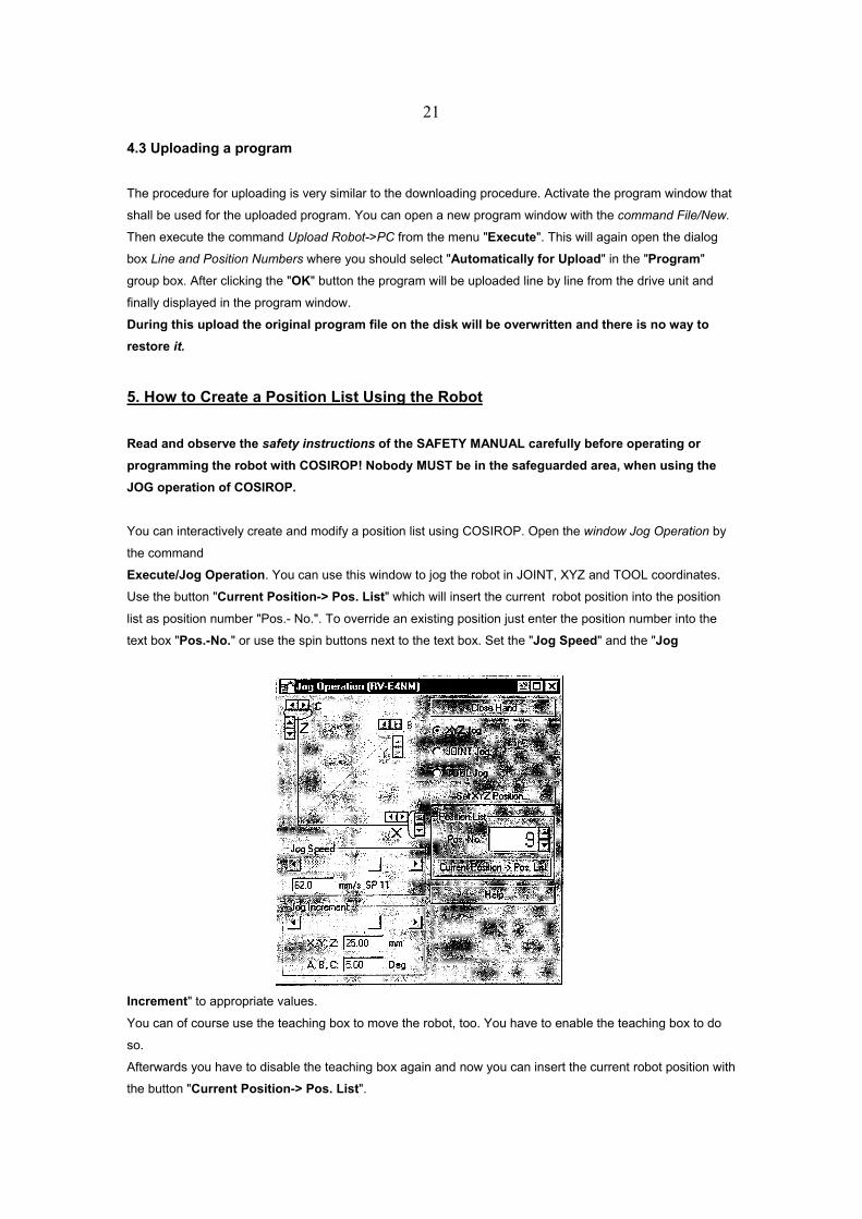
5. How to Create a Position List Using the Robot
Read and observe the safety instructions of the SAFETY MANUAL carefully before operating or programming the robot with COSIROP! Nobody MUST be in the safeguarded area, when using the JOG operation of COSIROP.
You can interactively create and modify a position list using COSIROP. Open the window Jog Operation by
the command
Execute/Jog Operation. You can use this window to jog the robot in JOINT, XYZ and TOOL coordinates.
Use the button "Current Position-> Pos. List" which will insert the current robot position into the position
list as position number "Pos.- No.". To override an existing position just enter the position number into the
text box "Pos.-No." or use the spin buttons next to the text box. Set the "Jog Speed" and the "Jog
Increment" to appropriate values.
You can of course use the teaching box to move the robot, too. You have to enable the teaching box to do
so.
Afterwards you have to disable the teaching box again and now you can insert the current robot position with
the button "Current Position-> Pos. List".
22
6. Haw to Send Commands to the Robot Read and observe the safety instructions of the SAFETY MANUAL carefully before sending commands to the robot.
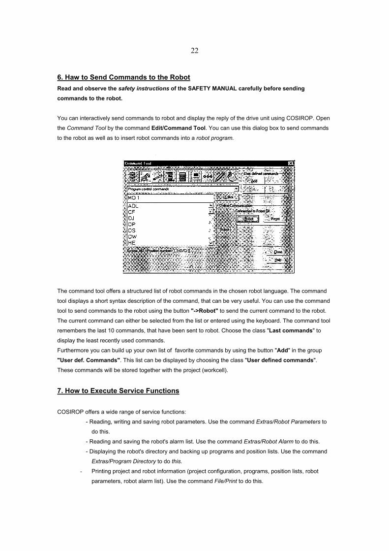
You can interactively send commands to robot and display the reply of the drive unit using COSIROP. Open
the Command Tool by the command Edit/Command Tool. You can use this dialog box to send commands
to the robot as well as to insert robot commands into a robot program.
The command tool offers a structured list of robot commands in the chosen robot language. The command
tool displays a short syntax description of the command, that can be very useful. You can use the command
tool to send commands to the robot using the button "->Robot" to send the current command to the robot.
The current command can either be selected from the list or entered using the keyboard. The command tool
remembers the last 10 commands, that have been sent to robot. Choose the class "Last commands" to
display the least recently used commands.
Furthermore you can build up your own list of favorite commands by using the button "Add" in the group
"User def. Commands". This list can be displayed by choosing the class "User defined commands".
These commands will be stored together with the project (workcell).
7. How to Execute Service Functions
COSIROP offers a wide range of service functions:
- Reading, writing and saving robot parameters. Use the command Extras/Robot Parameters to
do this.
- Reading and saving the robot's alarm list. Use the command Extras/Robot Alarm to do this.
- Displaying the robot's directory and backing up programs and position lists. Use the command
Extras/Program Directory to do this.
- Printing project and robot information (project configuration, programs, position lists, robot
parameters, robot alarm list). Use the command File/Print to do this.
23
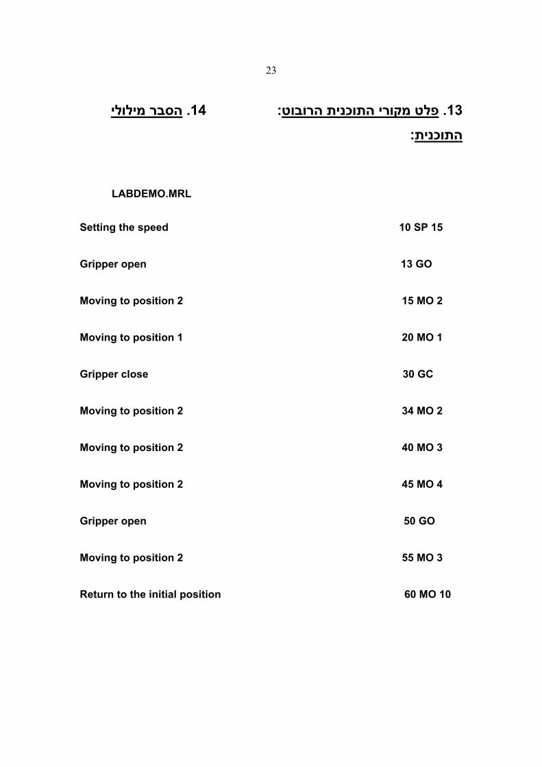
הסבר מילולי . 14: פלט מקורי התוכנית הרובוט. 13 :התוכנית
LABDEMO.MRL
Setting the speed 10 SP 15 Gripper open 13 GO Moving to position 2 15 MO 2 Moving to position 1 20 MO 1 Gripper close 30 GC Moving to position 2 34 MO 2 Moving to position 2 40 MO 3 Moving to position 2 45 MO 4 Gripper open 50 GO Moving to position 2 55 MO 3 Return to the initial position 60 MO 10