how to design new grippers by analogy - centro di ricerca ... to design new... · how to design new...
TRANSCRIPT

How to design new grippers by analogy G. Fantoni1, D. Gabelloni2 and J. Tilli3
1 Department of Mechanical, Nuclear and Production Engineering, University of Pisa, Italy
2 Department of Energy and Systems Engineering, University of Pisa, Italy
3 Interdepartmental Research Center "E.Piaggio", University of Pisa, Italy
[email protected], [email protected], [email protected]
Abstract
Design by analogy is a powerful technique which, in spite of the ease of use, misses some structure to be exploited at
maximum level. The paper investigates a possible system for structuring and expanding the possibilities related to the
application of design-by-analogy. The proposed technique is applied to the design of novel grippers and some of these
devices have been prototyped and tested. The study aims at: (i) increasing the design possibilities, (ii) analyzing and
comparing standard industrial grippers and academic ones with different devices that share some functionalities with
them and (iii) creating a repository that can be enlarged and reused for different applications.
Keywords
Design by analogy, functional analysis, gripper
Introduction and state of the art
Design by analogy is a useful methodology often adopted by professional designers, both at academic and industrial
level. Sometimes the analogy technique is adopted considering only elements belonging to the same domain of the
product under study (close-domain analogies). However, less often, different fields/sector are also investigated (cross
domain analogies) to expand the design possibilities. [1][2]
The latter approach is extremely useful, especially during the starting phase of the conceptual design, because it allows
to discover new ideas for the creation of novel products.
Nevertheless, while design by analogy is often performed without a formalized methodology in industry, different
design theory and problem solving methods based on design by analogy do exist in literature. For example Synectics [3]

is a structured approach to the creative problem solving activity, based on analogical thinking. It identifies four different
mechanisms which stimulates the creative thinking: direct analogy, personal analogy, symbolic and fantasy analogy.
A more structured method is the “theory of inventive problem solving” (TRIZ) [4]. The approach followed in TRIZ
considers initially the abstraction of the problem, hence the identification of the contradictions, then the research of the
solution by analogy within the 40 inventive principles. These principles have been extracted from a corpus of 2 million
patents [4] and have been demonstrated to be stable with the passing of time [5].
Mc Adams et al. [6] provide a measure of the similarity of the products through the concept of functions and flows.
Starting from the users’ needs, the functions that the product has to carry on are identified. After that, through an
appropriate database, those products sharing a functional similarity are chosen for doing a cross over.
Also the method developed by Fantoni et al. [7] is focused on the concept of function. They described a technique based
on functional analysis and on the analysis of functional synonyms and antonyms for the development of new ideas.
Another method which supports the design activity, stimulating at the same time creativity and the reasoning by
analogy, is the wordTree design-by-analogy method [8]. This method systematically guides the designers in the
identification of analogies and analogous domains thanks to the investigation of the lexical relationships among words
(hyperonims, meronims, synonyms, etc.).
A huge source of inspiration for new solutions comes also from nature. Several works deal with the systematic transfer
of biological knowledge into the engineering domain. Indeed, biomimetic design “offers enormous potential for
inspiring new capabilities for exciting future technologies” [9]. Several researchers have used biological analogies for
the generation of concepts ([10][11][12][13]).
In particular, through the concept of function, some of these works identify the biological elements to develop bio-
inspired concepts. For example Shu et al. [14] combined functional modeling and biomimetic design, by incorporating
biological phenomena into a function based design repository.
Similarly, Nagel et al. [15] presented a general method for the functional representation of biological systems through
systematic design techniques.
The systematic search for inspiration in the biological field pushed the research towards the development of databases
and softwares. For instance Chacrabarti [16] created a software called IDEA-INSPIRE, which uses a database of natural
and artificial systems classified by a verb-noun-adjective triplet. Vincent and Mann [5] constructed a condensed TRIZ
contradiction matrix (bio-triz matrix), that enables designer to abstract useful design information from biological
systems.

Robotic research has always shown a deep interest in bio-inspired grasping principles [17]: one of the most interesting
research activities is the gecko climbing system studied by Cutkosky's team. The climbing robot they developed is
based on Van der Waals’ forces and hyerarchical structures [18], while Matope et al. [19] transferred the concept to a
microgripper.
The last element we want analyze is the abstraction. This stage plays a major role in the early stages of engineering
design and is a valuable tool during the conceptual design phase[20]. Abstraction is also the first key step in TRIZ
algorithm [4] while it plays also a relevant role in functional decomposition [21][22][23].
As seen before, different works resort to the concept of function, since it provides an abstract representation of the
product. In engineering design, the definition or the comprehension of a system in terms of function, is a fundamental
aspect ([24][25][26]) that helps the designer in conceptualizing and evolving the design. Functional Analysis (FA) helps
the study of complex systems by breaking them down into simpler sub-functions.
Even more important, FA is fundamental in the conceptual stage of both original and adaptive design. Actually, during
the 60s in Germany, a huge amount of mechanical engineering literature and practical efforts have been devoted to the
development of catalogues of effects, principles and solutions. Those catalogues have the goal of providing abstract
representations of the functioning of objects, in order to help the designer in choosing the best solution among all those
able to solve the problem. Such a systematic encyclopaedia was developed by several authors and their results can be
found in [27] and [21].
The early contributions on functional analysis belongs to Value Engineering [2728]. Later Collins [29] produced a list
of all the mechanical functions that can be useful in a helicopter design. Pahl and Beitz [21] gave a fundamental
contribution to the generalization of the field, introducing the notions of basic flows (material, energy, signal) and
defined functions as operations on these flows.
Hundal [30] introduced a sixth general function (Branch) and, for each class, listed a series of functions in the form of
"verb + object" on a specific flow. Then Szykman et al. [31] extracted a large body of terms after an extensive review of
the literature, eliminating then synonyms and redundant descriptions. The effort promoted by NIST made soon evident
the need for synthesis and reorganization. One of the attempts in this direction was promoted by Little et al. [32], who
introduced the notion of functional basis. Stone and Wood [33] continued on the same track combining the
classification of functions in classes with the structure of a basis. These efforts of synthesis culminated in the
Reconciled Functional Base proposed by Hirtz et al. [34], where it is suggested a hierarchy of functions organized in
three levels. Further flexibility is offered by the development of correspondents, or synonyms, whose number and name
are left open.

Even if the RFB functional dictionary has been largely accepted and adopted, several works underlined the existence of
various problems. Among them, Bonaccorsi et al. [35] developed a wide and interconnected functional dictionary,
where vertical and horizontal relationships are mapped through synonyms and antonyms. Such extended dictionary
offers the possibility of designing alternative solutions by using functional similarities or variants.
In the following paragraphs the paper presents our design by analogy approach based on functional analysis. An
illustrative case of study is used to explore the application of the methodology to the design of new grippers. Then a
number of issues and future directions are summarized in the final section of this paper.
The methodology
In order to overcome fixation and to explore also lateral ideas, we approached the problem of designing new products
by using a crossover strategy (i.e. by using design by analogy). The idea behind is to find, in common days life, a source
of novel ideas inspired by the objects used to carry on a desired function. A large database of these objects can be
created in order to capture their behaviors, which concur to provide the researched functions. Each one of them can be
described in functional terms (e.g. using the dictionary in [34] and [35]) to enhance their retrieval. Unfortunately, even
if powerful, design by analogy is a very low structured technique, therefore, instead of starting with the analogies
research, we propose two steps: first the generalization and abstraction of the problem, then the clusterisation of the
results. While the first step enlarges the research domain, the second helps the designer in expanding the design space
into each cluster.
How to apply the method
Even if the method can be easily understood, we would like to apply it to a real case in order to better illustrate the
procedure through its steps. The application is the design of new grippers. Applying the design by analogy heuristic at
the problem level without using a structured method, we can find interesting sources of ideas in new industrial grippers
or in robotic hands, but such an analysis looks like much more a benchmarking than an inventive activity (Figure 1 left
arrow). Actually, both the number and the diversity of the found analogies are reduced if compared to the more
systematic analysis proposed here. For comparison the reader can refer to the seminal work of Novitskaya [36], where
she attempts to demonstrate the similarity between grippers and some structures belonging to absolutely different
technical systems. Even if the idea is correctly expressed and the case studied describes a gripping device, the approach
is far from being systematic.
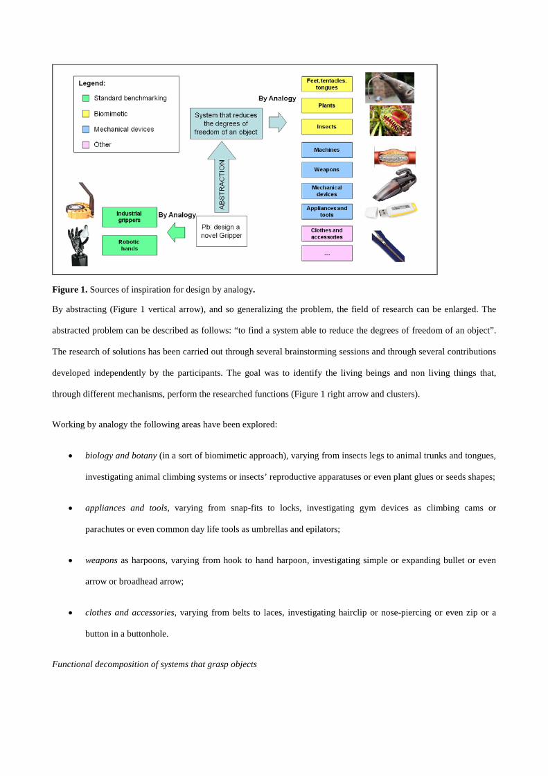
Figure 1. Sources of inspiration for design by analogy.
By abstracting (Figure 1 vertical arrow), and so generalizing the problem, the field of research can be enlarged. The
abstracted problem can be described as follows: “to find a system able to reduce the degrees of freedom of an object”.
The research of solutions has been carried out through several brainstorming sessions and through several contributions
developed independently by the participants. The goal was to identify the living beings and non living things that,
through different mechanisms, perform the researched functions (Figure 1 right arrow and clusters).
Working by analogy the following areas have been explored:
• biology and botany (in a sort of biomimetic approach), varying from insects legs to animal trunks and tongues,
investigating animal climbing systems or insects’ reproductive apparatuses or even plant glues or seeds shapes;
• appliances and tools, varying from snap-fits to locks, investigating gym devices as climbing cams or
parachutes or even common day life tools as umbrellas and epilators;
• weapons as harpoons, varying from hook to hand harpoon, investigating simple or expanding bullet or even
arrow or broadhead arrow;
• clothes and accessories, varying from belts to laces, investigating hairclip or nose-piercing or even zip or a
button in a buttonhole.
Functional decomposition of systems that grasp objects

Whichever system is selected, standard gripper and robot hand, or novel “grasping” device, it has been analyzed in a
formal way. For making the analysis as more rigorous as possible, a step-by-step top-down procedure has been chosen.
First of all, for each gripper, hand, device or animal, a suitable reference has been identified to clarify the functioning of
the system of interest. This is important in particular to understand the correct behavior, especially for biological
systems, which are not familiar for engineers. Then the decomposition moves towards the identification of the phases
[37] occurring during the utilization of the gripper, the actions performed by the animal or the use phases of the product.
Actually, the identification of the phases makes it easier to create a detailed functional description. Then each phase is
split into elementary functions and, to obtain homogeneous functional decompositions1
34
, they are labeled by using the
functional dictionary of Hirtz et al. [ ]. At the end, each gripper is classified according to the physical effects involved
during the functioning [38].
In particular, it is worth noting that the analysis of the elementary functions allows to map both the main function and
also those functions supporting the grasping. In order to reduce ambiguities, the handling based on grasping has been
split into standard phases and all the systems (included animals, devices etc..) are dealt according to such a set of phases
(see Figure 2).
1. Approaching 2. Coming into contact 3. Increasing the force
4. Securing
5. Lifting 6. Releasing
7. Monitoring
Figure 2. Standard phases sequences in assembly or goods handling.
In general parts grasping [39] consists of the following phases (shown in
Figure 2. Standard phases sequences in assembly or goods handling.
1 The flows are not considered in the analysis since the aim is to develop a tool able to expand design by analogy between different domains and flows play a secondary role in such analysis. Flows variation and transformation have been described in [7].

in case of a mechanical two fingers gripper):
1. approaching the object: the gripper is open and the robot system positions it close to the object;
2. coming into contact: the gripper is actuated and its surface touches the object surface (in case of contactless
handling the object is in the range of the force field generated by the gripper);
3. increasing the grasping force: the grasping force has to reach a value able to provide a stable grasping;
4. securing the object: the force stops increasing when the object stops moving independently from the
gripper;
5. lifting the object: in such conditions the gripper and the object are joined and the object can be lifted (if the
payload of both the robot and the gripper allows it);
6. releasing the object: at the macroscale, when the grasping force is removed, gravity helps to release the
object. At the microscale the problem is more complex, therefore other releasing strategies has to be found
[40];
7. monitoring the grasp: many different sensors (force and torque, stick-slip, contact sensors, etc.) are used to
monitor the contact and the effectiveness of grasping.
Phases like number 1 and 5 are usually performed by a robot or other handling system, while phase number 7 can be
done both locally, at the gripper level, or globally ,at robot or environment level (through fixed cameras).
Findings
Nowadays grippers are changing toward a more and more complex design to accomplish the most various tasks. Even if
research is pushing toward this direction, simple high efficiency grippers are still studied and produced for common
industrial operations. Actually, high performances usually implies high costs, which are not possible in a competitive
industrial scenario. Because of this fact high dexterous hands are mostly used in research activities or for particular
manipulation cases, while simple and reliable grippers are intensively exploited in industry.

Force
Compliance
n° DOF
Structural stiffness
Dexterity
Industrial Grippers Robot Hands
Figure 3. How parameters and performance vary from industrial grippers to robot hands.
Figure 3 shows the space of automatic grasping devices. On the left side different industrial grippers are shown, while
on the right one a few robot hands are presented. Examples of the two categories are vacuum cups, two finger
mechanical jaw for the industrial grippers, and Vassura’s hand or Waseda University Hands [17] for what concerns the
robotic end-effector.
The most important features for industrial grippers are the force, generally higher than in robotic devices, and the
structural stiffness, which influences the quality of grasping, positioning etc. [17]. Moreover the reduced number of
degrees of freedom increases the reliability of the gripper and reduces its cost. The robot hands, compared to the
industrial grippers, have an higher compliance and dexterity (mainly due to the increased number of DOFs) that allow
the manipulation of objects in a human-like way.
Occurrence analysis
Standard grippers. For each grasping principle [38] one standard gripper has been selected and analysed through
functional analysis (Figure 4). Since the other grippers exploiting the same grasping principle show almost the same
behaviour and the analysis can be considered nearly super imposable, a single device per principle is sufficient for the
purpose. As a note, the functions related to the lifting and realising phases have been skipped, since they are repetitive
and mainly based on robot capabilities and gravity, respectively.

Figure 4. Functional decomposition of the main grippers
Such decompositions can be considered as the baseline of the frequency analysis. The most occurring functions have
been plotted in the Pareto’s histogram shown in Figure 5. As expected, the most repeated functional verbs are those
related to the grasping and handling phases (to position, to bring close, to align, to connect, to mate, etc.). Some of them
are peculiar to the grasping process, while others, such as to mate and to connect, show how grasping benefits from high
coupling of gripper and object surfaces (often achieved through the deformability of the couple gripper/object).
Figure 5. Pareto histogram of the most occurring functions.

“Non conventional” grasping systems. The methodology presented in the previous chapter has been applied to create a
database that supports the designer, during the conceptual phase, in inventing new grippers. In order to overcome a rigid
and convergent approach to the problem we decided to explore devices or living beings and non living systems that acts
(also for short time periods) as grippers.
Definition of gripper
Grippers are defined as “a subsystems of handling mechanisms which provide temporary contact with the object to be
grasped [..] and ensure the position and orientation when carrying and mating the object to the handling equipment[..];
the term “gripper” is also used in cases where no actual grasping, but rather holding of the object where the retention
force can act on a point, line or surface [..]”[41].
So it is possible, and interesting, to find other systems not classified as grippers which match such a definition. Hence, a
database made up of about 150 elements has been created
(www.centropiaggio.unipi.it/~fantoni/D2_3_Grippers_by_analogy_final.xls). This database contains the names of the
“non conventional” grippers and the relative functional decompositions of the grasping phases. The entries of the
database are classified according to (i) the grasping mechanism (e.g. adhesion, grasping, pinching or punching) and (ii)
to the fields whose they belong to (e.g. biology, appliances and tools, clothes and accessories, weapons, etc..).
Examples of convergent suggestions in the database are seat belts, fish nets, mechanical devices; more divergent ideas
are for examples umbrellas, stents, car latches, etc. Moreover, even accidental and unwanted events as the nesting
between springs or the tangling of trousers into a gear systems or in the bicycle chain can be useful for inspiring novel
solutions for grasping.

Figure 6. Screenshot of the database (full database at www.centropiaggio.unipi.it/~fantoni/D2_3_Grippers_by_analogy_final.xls).
Figure 6 shows a part of the database with elements satisfy the definition. For instance during the use of a parachute, it
contains and constrains the air (it is a sort of temporary gripper for air). Another example is the brake that grasps/holds
the wheel decreasing the vehicle velocity by friction. One more interesting object is the stent, that is inserted in the
veins and arteries of the human body to counteract a localized flow constriction. Usually it is passed into the narrowed
locations and then it is inflated. Thus the balloon pushes the metallic stent that crushes the fatty deposits, opening up the
blood vessel and restoring the flow. Its functions of blocking the fat and holding the blood vessel in a open position
satisfy the gripper definition.
Some entries of the database show the same functional decomposition therefore they can be considered identical, even
if they are structurally different. These elements are in the column called correspondents. Indeed, the same functional
chains can be carried out through different elements and even different physical principles. For example a plug, a stent
and a latch perform the same functions to block and to hold.
Also for the non conventional grippers a frequency analysis has been performed, in order to identify where interesting
changes emerge from the comparison of the two groups (conventional vs non conventional). Figure 7 shows the results
concerning the top 30 functions.

Figure 7. Pareto histogram of most occurring functions in "non conventional" grippers.
In the case shown in Figure 7 the function “to deform” is split into two parts: gripper deformation and object
deformation. The sum of gripper deformation and mating is relevant and their synergy plays a key role (even more
important than in conventional grippers). This is probably due to the presence of biological systems, where the coupling
of grasping device and objects surface is necessary to increase reliability and to decrease the amount of energy
requested for the grasping (that, for example, is the base of the climbing of geckos, tree-frogs, squirrels, insects, etc..).
Case study
Robotic unloading of goods from containers
In time logistic companies are becoming more and more interested in automating the unloading of mass goods. The
reasons rely on process cost and workers’ issues (long-term physical impacts, frequent absences due to chronic illness
and high turnover). One of the most challenging problems is the grasping and handling of deformable and weight sacks
(e.g. coffee and cocoa sacks) stacked and tangled one with the others. Such problem has to be solved in the RobLog
project (Cognitive Robot for Automation of logistic Processes), whose purpose is to unload containers automatically.
One of the basic steps of the project is the design of a grasping systems able to deal with objects having different
properties, such as dimension, weight, porosity and flexibility. In the next paragraph some new grippers, which have
been designed thanks to the presented methodology, will be shown.
Intrusive grippers.

At the present two workers use two hooks each to grasp and handle coffee sacks. The hooks pierce the jute sack, the
two workers pull the sack from the pile, lift it and throw it over a pallet. The hooks (the steel wire has an average
diameter of 4 mm) leaves small holes on the jute sack that can be tolerated within the process.
Intrusive grippers, as the above mentioned hooks, are frequently used in sacks handling or in food handling. The
Schmaltz Gripper [17][42] is a gripping system used for the handling of flexible, non-rigid components or materials
which cannot be grasped by using vacuum, e.g. fabric sheets, textiles, foam materials. Its gripping behaviour is achieved
by the intrusion of the needles within the fibers of the object. The same principle has been also adopted to handle frozen
fillets of salmon or meat [43].
Other techniques use of two rotating rollers able to entangle the textile of the sack [44]. The two rollers come into
contact with each other and with the sack to be grasped. The rollers start counter-rotating while the sack textile is
dragged by the friction forces and the sack moves into the end-effector. When a certain quantity of the sack is between
the rollers, the sack can be lifted thanks to the forces exerted by the rollers. It really looks like to what happens when
trousers come into the bicycle chain.
Kirchheim et al. [45] described a gripper supplied with four “claw” systems with three concentric claws per system. The
claw systems move vertically and rotate at 90° degrees. The edge of the claw pierces the jute, while the roto-
translational motion produces the form closure. The gripper is really robust, but it requires a large amount of force to
pierce the jute sack and to twist to assure the form closures.
This very short state of the art in coffee sacks handling showed that these four grippers (hooks, needles, rotating
cylinders and claw) are similar to fish-hooks, forks, pull-over mill and a corkscrew, respectively. Such grippers are not
automatized yet in an automatic unloading system and some of them suffer from reliability matter when the goods are
irregular, nested, etc..
Designed grippers
The database (www.centropiaggio.unipi.it/~fantoni/D2_3_Grippers_by_analogy_final.xls) has been clustered and a
limited number of concept has been extracted and implemented into real prototypes suitable for coffee sacks. Most of
them can be used for the grasping and the lifting of heavy deformable objects, whose surface can be punched.
The following Figure 8 presents some of them.

Figure 8. Some of the devices developed.
Sewing Gripper. The concept of the gripper is based on that of sewing machine: a wire, in this case a metallic wire such
as a spring, is sewn clockwise on the jute sack to be grasped by an electric motor. Once enough spires are inserted into
the material, the grasping is performed and the sack can be pulled out. To release the objects, the spring is turned
counterclockwise by the electric motor.
Inflatable gripper. The inflatable gripper changes its geometry to achieve the grasping. The main structure is a metal
tube. A deformable membrane, surrounded by a braided sleeve, is the part of the gripper which deforms itself to switch
from the insertion/extraction to the grasping configuration. The working principle is similar to the cited stent.
Cam gripper. This is an intrusive gripper, whose grasping capability is due to the contact between two or more metallic
retractable shelves of the gripper, and the walls of the object to be grasped. The gripper is inserted into the object with

the shelves in the retracted position, then they are elongated and the object is pulled. To release the objects, the
extensible components are retracted and the gripper is extracted.
Reverse Scissor. This gripper, like the ones presented above, is based on the intrusion principle. The rod with the two
shelves aligned with its axis is inserted into the object. Then the shelves are rotated and blocked firmly in an opened
position. Once the object is pulled to the final position, the shelves are rotated to the original configuration, then the
whole gripper is extracted from the sack.
All the prototyped grippers (except the reverse scissors gripper that was made in ABS by rapid prototyping)
demonstrated good grasping capabilities and a maximum pulling force varying from 200N to 350N. The holes
generated into the jute sack remain within the specifications even if a miniaturisation process is necessary in the case of
inflatable gripper and in general can be appreciated also in the other devices.
Conclusions and future works
In this paper a systematic methodology based on design by analogy has been presented. The method promote the search
for analogies “out of the box”. The method, starting from the problem generalization, identifies the solutions (
belonging to different fields from with common objects to living beings etc..) to the general problem and locates the
found elements in a suitable database. The database contains for each element/object (that performs the macro-function
of grasping in a particular way) also its detailed functional decompositions that allows further searches in the database.
The application of this framework allowed an extension of the solutions space both at theoretical level and at practical
one. Actually, it has been also used as a guide to the design and prototyping of new grippers for coffe sack automatic
handling.
The results we achieved are of interest for three reasons:
i) from a methodological point of view the process can be extended to other fields and the method can be
used as a creativity support during the design phase;
ii) from the grasping side it is possible to notice that the grasping phase is highly affected by the ability of the
gripper surface to couple with the object surface, the study of such adaptable surface can be the key to
enhance (standard) gripper performances;
iii) design by analogy makes possible to conceive other grippers also in different fields as for example for
grasping boxes, tires, pottery, etc.. The database

(www.centropiaggio.unipi.it/~fantoni/D2_3_Grippers_by_analogy_final.xls) can be used a source for
suggestions or extended in order to enlarge the design space for grasping and handling systems.
Funding acknowledgements
This work was supported by RobLog Project (FP7 ICT-270350) and LILIT Project (PAR FAS REGIONE TOSCANA
Linea di Azione 1.1.a.3).
Reference
1. Christensen BT and Schunn CD. The Relationship of Analogical Distance to Analogical Function and Pre-
inventive Structure: The Case of Engineering Design. 2007, Memory & Cognition, 35(1), 29-38.
2. Eckert C, Stacey M and Earl C. References to Past Designs. IN J.S. Gero and N. Bonnardel (eds.), Studying
Designers ’05, 2005 Key Centre of Design Computing and Cognition, University of Sydney, 3-21.
3. Gordon WJJ. Synectics: The development of creative capacity. Oxford, England: Harper. (1961)
4. Altshuller G. Creativity as an Exact Science, Gordon and Branch Publishers (1984), Luxembourg
5. Vincent JFV and Mann DL. Systematic technology transfer from biology to engineering. Philosophical
Transactions of the Royal Society London A 360, 159–173, (2002).
6. McAdams D and Wood K. Quantitative Measures for Design by Analogy, Proceedings of ASME IDETC/CIE,
Baltimore, Maryland, 2000, DETC2000/DTM-14562.
7. Fantoni G, Taviani C and Santoro R. Design by functional Synonyms and Antonyms: a structured creative
technique based on functional analysis. Proceedings of the Institution of Mechanical Engineers, Part B, Journal of
Engineering Manufacture, 2006.
8. Linsey JS, Wood KL and Markman AB. Increasing innovation: presentation and evaluation of the wordtree
designbyanalogy method. Proceedings of the ASME 2008, IDETC/CIE 2008, August 3-6, 2008, Brooklyn, New
York, USA
9. Bar-Cohen Y. Biomimetics—using nature to inspire human innovation. Journal of Bioinspiration and Biomimetics
1(1), 1–12, 2006.
10. Dieter GE. Engineering Design: A Materials and processing Approach. /3e, McGraw-Hill, 2000.
11. Ulrich KT and Eppinger SD. Product Design and Development. Boston: McGraw–Hill/Irwin, 2004.
12. Otto K and Wood K. Product Design, Techniques in Reverse Engineering and New Product Development. Prentice
Hall, NJ, 2001.
13. Hyman B. Fundamentals of Engineering Design. Second Edition, Prentice Hall, NJ, 2003.

14. Shu LH, Stone RB, McAdams DA et al. Integrating function-based and biomimetic design for automatic concept
generation. Proc. ICED, Paris, 2007.
15. Nagel JKS, Nagel RL, Stone RB et al. Function-Based, Biologically-Inspired Concept Generation. AI EDAM-
Biologically Inspired Design, 24(4) on Feb. 16, 2010.
16. Chakrabarti A, Sarkar P, Leelavathamma et al. A functional representation for aiding biomimetic and artificial
inspiration of new ideas. AIEDAM, 2005, Analysis and Manufacturing 19, 113–132.
17. Kato I. Mechanical Hands Illustrated, Survey Japan, 1982.
18. Kim S, Spenko M, Trujillo S, et al. Whole body adhesion: hierarchical, directional and distributed control of
adhesive forces for a climbing robot. IEEE International Conference on Robotics and Automation, Roma, Italy, 10-
14 April 2007.
19. Matope S and VD Merwe AF. Micro-material handling employing Van der Waals forces. Proceedings of the
COMA, 2010, Stellenbosch University, 3 February -5 February 2010, p.261-267.
20. Voland G. Engineering by Design. Upper Saddle River, NJ: Pearson Prentice–Hall, 2004.
21. Pahl G and Beitz W, Engineering Design: A Systematic Approach, Design Council, 1984.
22. Ullman D. The Mechanical Design Process, McGraw-Hill, New York, 2nd edition, 1997.
23. Ulrich KT and Eppinger S. Product Design and Development, McGraw-Hill, NY, 1995.
24. Hubka V, Andreasen M, Eder W et al. Practical Studies in Systematic Design, Butterworths, London, (advisory
editor) 1988.
25. Otto K and Wood K. Product Design: Techniques in Reverse Engineering and New Product Development. Prentice
Hall, Upper Saddle River, NJ, 2000.
26. Gero JS and Kannengiesser U. The situated function – behaviour – structure framework, Artificial Intelligence in
Design’02, 89-104, JS Gero (ed.),Kluwer Academic Publishers, Dordrecht. Printed in the Netherlands, 2002.
27. Rodenacker W. Methodisches Konstruieren. Springer-Verlag, Berlin, 1971.
28. Miles L. Techniques of Value Analysis Engineering, McGraw-Hill, 1972.
29. Collins J, Hagan B, and Bratt H. The Failure-Experience Matrix - a Useful Design Tool. Transactions of the
ASME, Series B, Journal of Engineering in Industry, 98:1074-1079, 1976.
30. Hundal MS. Systematic Mechanical Designing: A Cost and Management Perspective. ASME Press, New York,
1997.

31. Szykman S, Racz JW and Sriram RD. The Representation of Function in Computer-based Design. Proceedings of
the 1999 ASME Design Engineering Technical Conferences (11th International Conference on Design Theory and
Methodology), Paper No. DETC99/DTM-8742, Las Vegas, NV, September.
32. Little A, Wood K and McAdams D. Functional Analysis: A Fundamental Empirical Study for Reverse
Engineering, Benchmarking and Redesign, Proceedings of the ASME Design Theory and Methodology
Conference, Sacramento, California, 1997.
33. Stone R and Wood K. Development of a Functional Basis for Design. Journal of Mechanical Design, 122(4):359-
370, 2000.
34. Hirtz J, Stone R, McAdams D et al.. A Functional Basis for Engineering Design: Reconciling and Evolving
Previous Efforts. Research in Engineering Design 13, 2002, 65-82.
35. Bonaccorsi A and Fantoni G. Expanding the Functional Ontology in Conceptual Design. ICED'07 Paris, France.
36. Novitskaya E. Transformation of structurally similar elements of technical system, Proceedings of the European
TRIZ Association, TRIZ Future 2003, Aachen, Germany, November 2012.
37. Gabelloni D, Fantoni G, Apreda R et al.. On the link between features and functions, Proceeding of the ICED11, 15
- 18 August 2011, Technical University of Denmark, Copenhagen.
38. Tichem M, Lang D and Karpuschewski B. A classification scheme for quantitative analysis of micro-grip
principles, Proc. of the 1st IPAS'2003, 17-19 March, Bad Hofgastein, Austria.
39. Blanes C, Mellado M, Ortiz C et al.. Review. Technologies for robot grippers in pick and place operations for fresh
fruits and vegetables. Spanish Journal of Agricultural Research, 9(4), 2011.
40. Fantoni G and Porta M. A Critical Review of Releasing Strategies in Microparts Handling, IPAS, Vol. 260Springer
(2008) , p. 223-234.
41. Monkman GJ, Hesse S, Steinmann R., Schunk H., Robot Grippers, Wiley-VCH, 2007.
42. http://www.schmalz.com/np/pg/produkte?hier=155-3886-3892
43. Gjerstad TB, Lien TK and Buljo JO. Handle of Non-Rigid Products using a Compact Needle Gripper. 39th CIRP
International Seminar on Manufacturing Systems; 2006.
44. Kazerooni H and Foley C. A Robotic Mechanism for Grasping Sacks. Trans. on Automation and Engineering, vol.
2, no. 2, pp. 111-120, 2005
45. Kirchheim A, Burwinkel M and W. Echelmeyer. Automatic Unloading of Heavy Sacks from Containers. IEEE
International Conference on Automation and Logistics, 2008. ICAL 2008.

Corresponding Author Contact details
Fantoni Gualtiero [email protected] Department of Mechanical, Nuclear and Production Engineering Largo Lucio Lazzarino,1 - Pisa - 56122 - Italy 0039-050-2218128