how to configure the parameter of rf1276....user guide of rf1276 - 1 - 2015-8-12 how to configure...
TRANSCRIPT

User Guide of RF1276
- 1 - 2015-8-12
How to configure the parameter of RF1276.
RF1276 series is a low cost, ultra-low power, high performance transparent two way semi-duplex LoRa modulation transceiver with operation at 169/433/868/915 Mhz. It integrates with high speed MCU from ST and high performance RF IC SX1276. The parameter configuration is necessary before we use the RF module RF1276. The step of configuration is as follow. 1, The installation of USB adaptor driver. We provide the USB adaptor PL2303 for the parameter configuration. It is used as a bridge for USB and UART port converter. The device is as below shown.
The module connects with USB adaptor as the below pic shown.

User Guide of RF1276
- 2 - 2015-8-12
2, Download the USB driver via this link. And install the driver in the windows PC. http://www.appconwireless.com/DownloadShow.asp?id=375 3, Plug the USB adaptor in the PC. And check whether the PC recognize the USB adaptor in the device management.

User Guide of RF1276
- 3 - 2015-8-12
4, Open ‘RF tool for RF1276’ as the administrator authority. There is shown ‘closed’ in the bottom. Click ‘Open’ to open the serial port.
5, After the serial port is opened, the bottom of RF tool will be shown ’Opened’. It is very import to click ’Read All’ to read the initiate configuration. DO NOT click the ‘Write ALL’

User Guide of RF1276
- 4 - 2015-8-12
6, In the bottom of RF tool, it will be shown ‘Succeed’. If it is shown ‘Time
out’, please check the connection of USB adaptor.

User Guide of RF1276
- 5 - 2015-8-12
7, After read the parameter successfully, the user can configure the parameter as
they requirement. The parameters can be set via ‘Write All’ operation. It will
show ’Successful’ to indicate the parameter set successfully.
How to make the two RF1276 modules communication?
Users can use the SSCOM to simulate the two module communication via two
computers or one computer. If you need to test the range of RF module, please
choose two computers. The SSCOM can download via this link.
http://www.appconwireless.com/DownloadShow.asp?id=373
We use one computer connected two module as the example to show the process
of communication. RF1276 works in the normal mode.
Firstly, users should install the serial device such as USB adaptor PL2303. It can
check the two devices in the device management.
User Guide of RF1276
- 6 - 2015-8-12
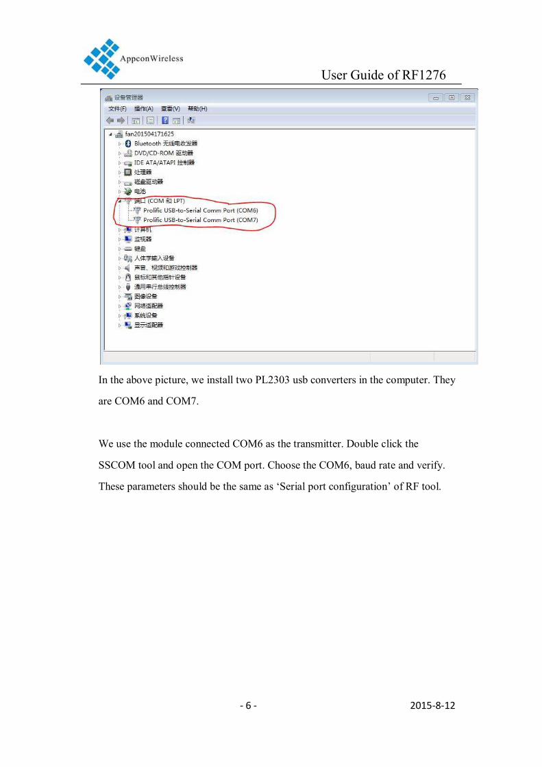
In the above picture, we install two PL2303 usb converters in the computer. They
are COM6 and COM7.
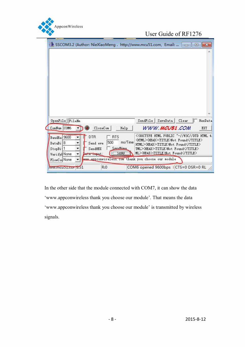
We use the module connected COM6 as the transmitter. Double click the
SSCOM tool and open the COM port. Choose the COM6, baud rate and verify.
These parameters should be the same as ‘Serial port configuration’ of RF tool.

User Guide of RF1276
- 7 - 2015-8-12
And then we input the data such as ‘www.appconwireless thank you choose our
module’ and click ‘SEND’
User Guide of RF1276
- 8 - 2015-8-12
In the other side that the module connected with COM7, it can show the data
‘www.appconwireless thank you choose our module’. That means the data
‘www.appconwireless thank you choose our module’ is transmitted by wireless
signals.

User Guide of RF1276
- 9 - 2015-8-12
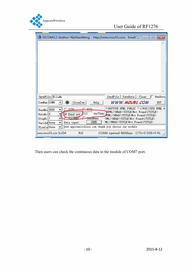
If user need transmit the data continuously, the ‘Send eve’ option should be check.
The ‘ms/Time’ is the period of transmit. In the example, we choose 500ms as the
period.
User Guide of RF1276
- 10 - 2015-8-12
Then users can check the continuous data in the module of COM7 port.

User Guide of RF1276
- 11 - 2015-8-12
When RF1276 is transmitting data, the LED of module will show RED.

User Guide of RF1276
- 12 - 2015-8-12
When RF1276 is receiving data, the LED of module will show BLUE.

User Guide of RF1276
- 13 - 2015-8-12
The explanation of data loss in the transmission.
RF1276 is LoRa modulation module. So the air data rate is very low. When the
data rate of the serial port is very high, the data will be lost because of the data
overflow.
The air data rate of RF1276 depends on two parameters, RF_Factor& RF_BW.
The bellowing chart is the relationship of them.
RF_Factor /Chips
RF_BW /kHz
Equivalent air data rate
/Kbps
Sensitivity /dBm
128 500 21.88 -117
256 500 12.5 -120
512 500 7.032 -123
1024 500 3.908 -126
2048 500 2.148 -129
4096 500 1.172 -132
RF_Factor
/Chips RF_BW
/kHz
Equivalent air data rate
/Kbps
Sensitivity /dBm
128 250 10.94 -120
256 250 6.25 -123
512 250 3.516 -126
1024 250 1.954 -129
2048 250 1.074 -132
4096 250 0.586 -135

User Guide of RF1276
- 14 - 2015-8-12
RF_Factor
/Chips RF_BW
/kHz
Equivalent air data rate
/Kbps
Sensitivity /dBm
128 125 5.47 -123
256 125 3.125 -126
512 125 1.758 -129
1024 125 0.977 -132
2048 125 0.537 -135 Default setting
4096 125 0.293 -138
In the below test, we set the RF_Factor=2048 and RF_BW=125. We can
calculate the air data rate only 537bps through the chart.
If the transmitting period is 500ms, we transmit the data packet of ’
www.appconwireless thank you choose our module’ (total 50bytes). We send the total
data up to 850bytes.

User Guide of RF1276
- 15 - 2015-8-12
We can see all 850bytes in the receiver module.

User Guide of RF1276
- 16 - 2015-8-12
If we set the period to 400ms, and send 1250 bytes data.

User Guide of RF1276
- 17 - 2015-8-12
The receiver can get all 1250 bytes.

User Guide of RF1276
- 18 - 2015-8-12
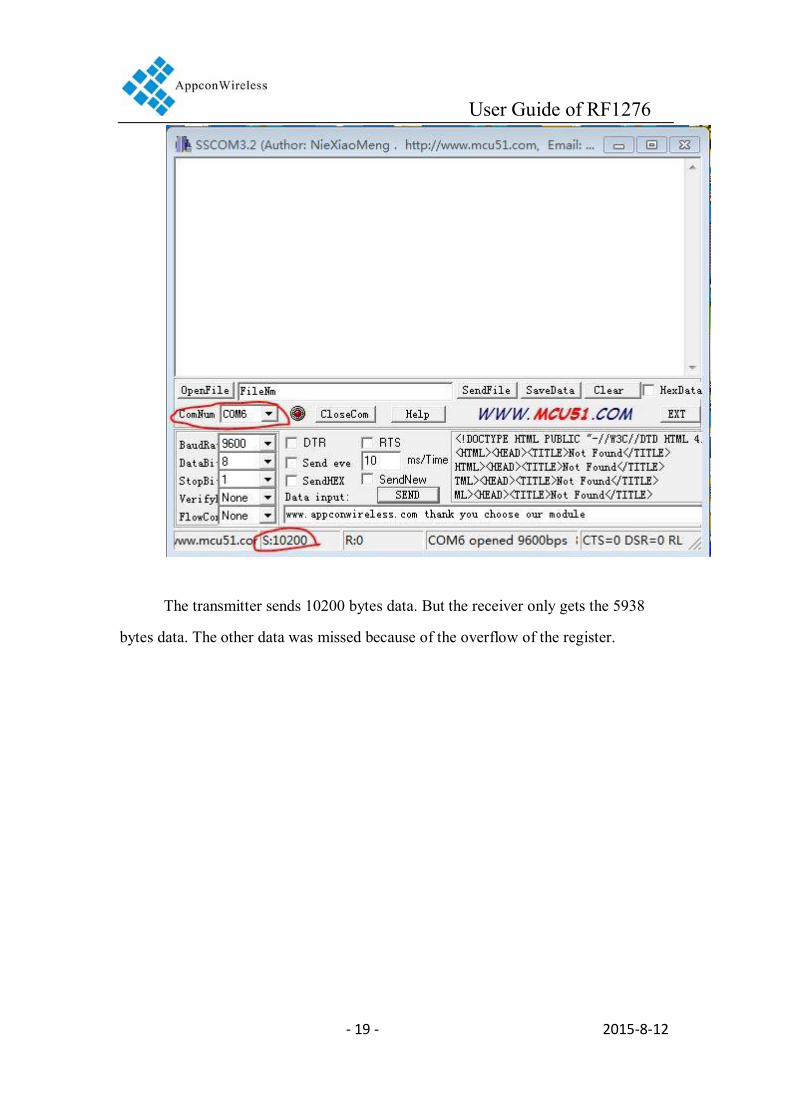
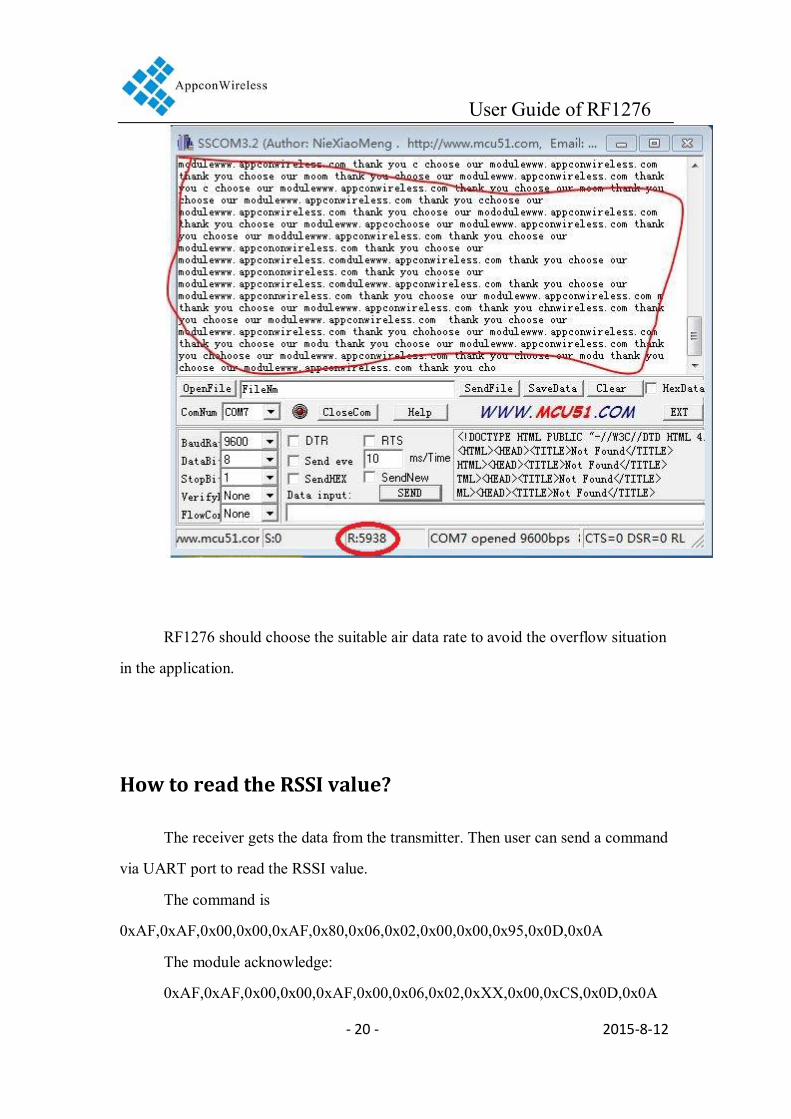
If we set the period to 10ms, we send the same data packet.
User Guide of RF1276
- 19 - 2015-8-12
The transmitter sends 10200 bytes data. But the receiver only gets the 5938
bytes data. The other data was missed because of the overflow of the register.
User Guide of RF1276
- 20 - 2015-8-12
RF1276 should choose the suitable air data rate to avoid the overflow situation
in the application.
How to read the RSSI value?
The receiver gets the data from the transmitter. Then user can send a command
via UART port to read the RSSI value.
The command is
0xAF,0xAF,0x00,0x00,0xAF,0x80,0x06,0x02,0x00,0x00,0x95,0x0D,0x0A
The module acknowledge:
0xAF,0xAF,0x00,0x00,0xAF,0x00,0x06,0x02,0xXX,0x00,0xCS,0x0D,0x0A
User Guide of RF1276
- 21 - 2015-8-12
The OxXX is the RSSI relative value. The eventual value of RSSI is RSSI=-164+XX.
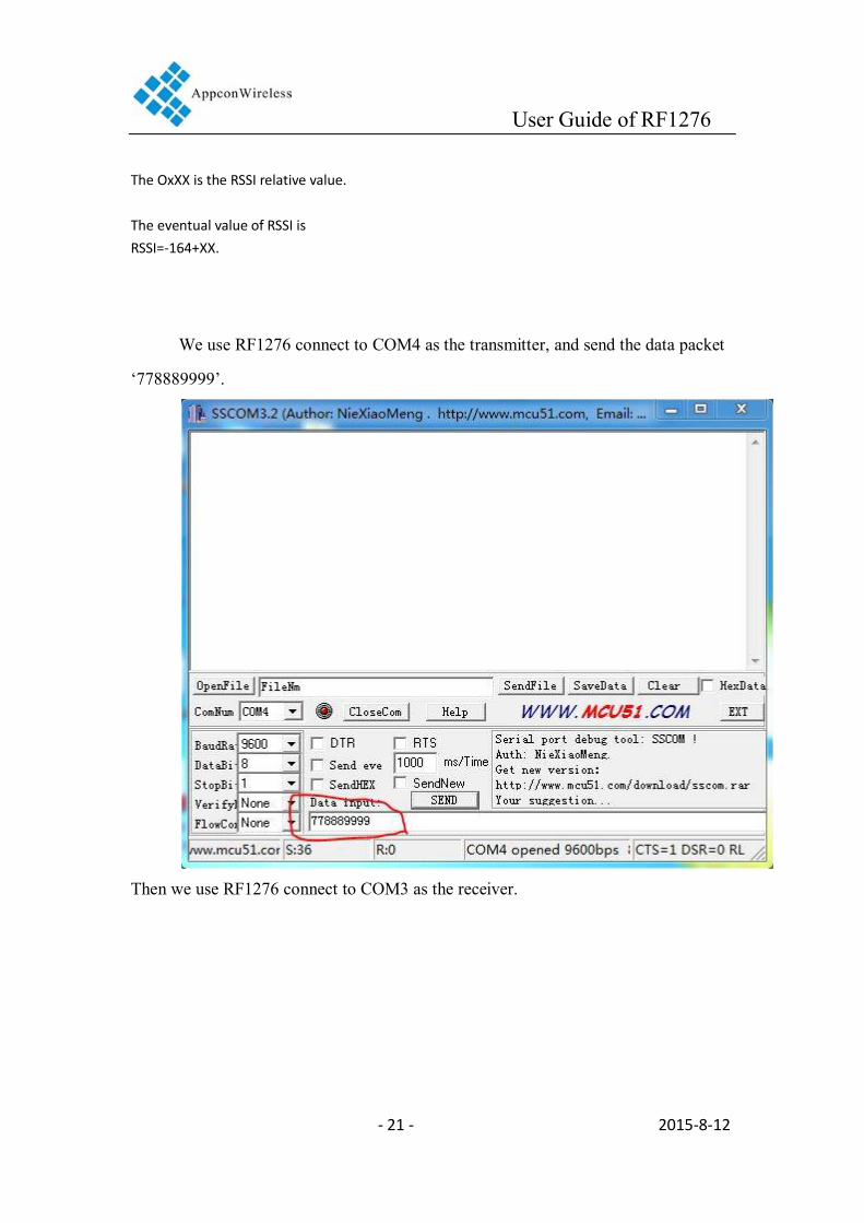
We use RF1276 connect to COM4 as the transmitter, and send the data packet
‘778889999’.
Then we use RF1276 connect to COM3 as the receiver.
User Guide of RF1276
- 22 - 2015-8-12
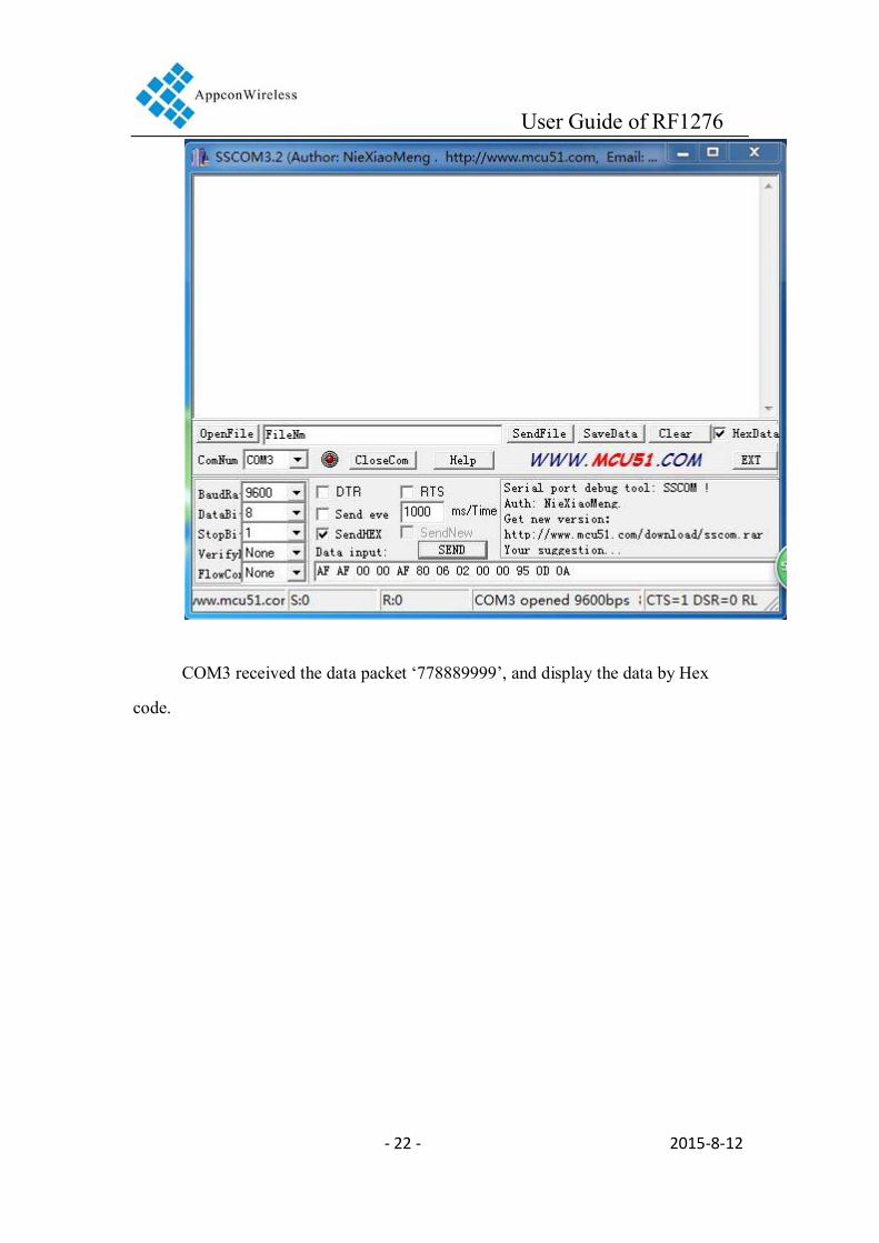
COM3 received the data packet ‘778889999’, and display the data by Hex
code.

User Guide of RF1276
- 23 - 2015-8-12
Then the receiver (COM3) input the RSSI reading command ‘AF AF 00 00 AF
80 06 02 00 00 95 0D 0A’ by hex. And click ‘send’

User Guide of RF1276
- 24 - 2015-8-12
The module will reply the SSCOM result ‘AF AF 00 00 AF 00 06 02 32 00 47
0D 0A’.

User Guide of RF1276
- 25 - 2015-8-12
The relative RSSI value is 50dBm(32 is the hex value, 50 is the decimal value). The eventual value of RSSI is
RSSI= -164 + 50 = -114 dBm