how to apply for electricity connection
TRANSCRIPT

How to Apply For Electricity Connection
This handbook is published by SP Group
April 2021
Procedures and requirements highlighted in this handbook
are correct at the time of printing. Any changes that may
arise will be reflected in the next edition.
ISBN: 981-04-6932

i
Important Contact Numbers
Tel No Fax No
General Enquiry
Application for Connection to Transmission System
6916 7200
Consumer Connection Agreement
Contracts Section 6916 7231
Testing and Turn-on Appointment
Supply Application Section 6916 7200
Installation Section 6916 9386
Opening of Utilities Accounts
Enquiry 1800-222 2333 6304 8229
Endorsement of Substation Drawings
East zone 6916 8557
West zone 6916 8679
Installation of Meters
Elect Meters 6916 8555

ii
Table of Contents
1. General Information ......................................................................................................................... 1
1.1 Introduction .............................................................................................................................. 1 1.2 Connection Voltages and Supply Frequency ........................................................................... 1 1.3 Submission of Application ........................................................................................................ 2 1.4 Provision of a Substation .......................................................................................................... 3 1.5 Domestic Premises and Load Requirement not exceeding 45kVA ........................................... 3 1.6 Meter........................................................................................................................................ 3 1.7 Tariffs for Non-Contestable Customers .................................................................................... 4 1.8 Payments for Electricity Charges by Contestable Customers.................................................... 4 1.9 Opening Account and Payment of Security Deposit for Use of System (UOS) Charges ........... 4 1.10 Termination of Account ............................................................................................................ 4 1.11 Disconnection of Service Cables upon Termination of Account ............................................... 4 1.12 General .................................................................................................................................... 5
2. Application For Load Connection .................................................................................................... 6
2.1 Distribution Connection ............................................................................................................ 6 2.2 Consultation ............................................................................................................................. 6 2.3 Application ............................................................................................................................... 6 2.4 Processing of Application ......................................................................................................... 6 2.5 Commencement of Work ........................................................................................................ 7 2.6 Type of Premises ...................................................................................................................... 7 2.7 Premises in Private Housing, Industrial Estates, Commercial Developments Requiring Provision
of Low Tension (LT) Distribution Network ................................................................................. 8 2.8 Provision of Substation ............................................................................................................. 9 2.9 Service Connection Cables ...................................................................................................... 9 2.10 Opening of Account for Upgrading/ Downgrading of Electricity Supply (Assuming No
Change in Contestability Status) ............................................................................................... 9 2.11 Consultation for Transmission Connection ............................................................................. 10 2.12 Application for Transmission Connection ............................................................................... 10 2.13 Lead-Time for Application of Transmission Connection ......................................................... 10 2.14 Technical Requirements of Distributed Generation and New Extra / Ultra High Tension
Connection............................................................................................................................. 11
3. Transmission Charges .................................................................................................................... 12
3.1 Connection Agreement .......................................................................................................... 12 3.2 Use of System (UOS) Charges ................................................................................................ 13
4. Energisation and Turn-on Procedure ............................................................................................ 18
4.1 General .................................................................................................................................. 18 4.2 Premises Electrical Installations that are previously Inspected and Energised ......................... 18 4.3 Premises with Direct Connection from SPPA’S Transmission System....................................... 19 4.4 Non-Domestic Premises ......................................................................................................... 20 4.5 Booking an Appointment ....................................................................................................... 21 4.6 Making an Appointment for Energisation of Service Connection Direct from SPPA’s
Transmission System - Load Requirement not Exceeding 45kVA ........................................... 21 4.7 Load Requirement Exceeding 45kVA Up to 22kV Supply Voltage ......................................... 22 4.8 Submission of Application for New EHT and HT Consumers who wish to be Contestable at
Time of Turn-On ..................................................................................................................... 22 4.9 Premises with Indirect Connection - Load Requirement not Exceeding 45kVA (i.e. Premises in
a Multi-Metered Development) .............................................................................................. 23 4.10 Load Requirement Exceeding 45kVA (Multi-Metered Building Scheme) ................................ 23 4.11 Modification to an Existing Electrical Installation ..................................................................... 24
iii
4.12 Submission of Completion Certificate for Modification of Small Electrical Installation (Exempted from Licensing) .................................................................................................... 24
4.13 Licence to Use or Operate an Electrical Installation ................................................................ 24 4.14 Certificates and Statements for First Energisation of Service Connection ............................... 24 4.15 Statement of Turn-On of Electricity ......................................................................................... 25 4.16 Lead-Times for Application for Service Connection ............................................................... 25 4.17 Normal Lead Time for Energisation of Service Connection Up to 22kV .................................. 26 4.18 Fast Track Connection Scheme .............................................................................................. 27 4.19 Notes to be Read in Conjunction with Application Procedure ............................................... 28 4.20 Opening an Account .............................................................................................................. 28 4.21 Handover of Completed Substation ....................................................................................... 29 4.22 Installation of Current Transformer Operated Meters ............................................................. 30 4.23 Procedure for Application for Licence to Use or Operate an Electrical Installation ................. 30 4.24 Conditions for the Issue of the Licence .................................................................................. 30 4.25 Procedure for De-Energisation / Disconnection of Service Cables ......................................... 31
5. Customer's Installation Requirements ........................................................................................... 32
5.1 Requirements for HT and LT Connection for 22kV and below................................................ 32 5.2 Requirements for 22kV and 6.6kV Customer Connection ....................................................... 34 5.3 Requirements for LT Supply Connection ................................................................................ 35 5.4 Requirements for EHT Connection for 66kV and 230kV ......................................................... 35 5.5 Requirements for 66kV and 230kV Customer Connection ..................................................... 35 5.6 Information on SPPA Network Earthing System for 230kV, 66kV and 22kV ............................. 37
6. Metering Requirements ................................................................................................................ 38
6.1 General .................................................................................................................................. 38 6.2 Location of Meter ................................................................................................................... 39 6.3 Grouping of Meters ................................................................................................................ 40 6.4 Meter Service Board Specifications (Single-Phase and 3-Phase Services, not Exceeding 100A
per Phase) .............................................................................................................................. 42 6.5 Wiring, Layout of Meters, MCBs, etc. in Centralised Meter Rooms, Meter Compartments /
Riser Ducts / Cupboards ......................................................................................................... 42 6.6 Submission of Layout Plans..................................................................................................... 42 6.7 Meters for 3-Phase Low Tension Connection (Exceeding 100A per Phase) ............................ 42 6.8 Meter Installation Requirements ............................................................................................. 43 6.9 Enclosure ................................................................................................................................ 44 6.10 High Tension/ Extra-High Tension Metering ........................................................................... 44 6.11 Specifications for Metering Current Transformers .................................................................. 44 6.12 Specifications for Voltage Transformers ................................................................................. 45 6.13 Testing of Metering CTs and VTs’ ........................................................................................... 45 6.14 Miscellaneous Metering Requirements .................................................................................. 46 6.15 Contestable Customers .......................................................................................................... 47 6.16 Maintenance Procedure ......................................................................................................... 48
7. Appendices .................................................................................................................................. 49
1 Letter of Consent for Submission of Application for Electricity Supply …………………… .................... 50 3 Letter of Consent from the Landlord / Management Corporation (Form CS/3) ............................ 51 4 Letter of Consent from Housing & Development Board (Form CS/3H) ………….. ............................. 52 5 Request to Handover Substation ………………………………………………… .......................................................... 53 6 Application for Water, Electricity, Gas and/ or Refuse Collection Services…………………................ 54 7 Application for Interbank GIRO ………………………………………………….…… ..................................................... .56 9 Types and Layout of Substation …………………………………………………..…....................................................... 57 10 Submission of Substation Site and Layout Plans ………………………………….. .............................................. 58 11 22kV/LV Substation (8 Drawings) ………………………………………………… ......................................................... 59 12 Heavy Aluminum Louvered Doors for Electric Substation (5 Drawings) …… ..................................... 67 13 Gate Details (1 Drawing)…………………………………………………….. ……… ............................................................. 72 14 Checklist for Substation Building Plan Submission ……………………………….. ............................................. 73 15 Substation Layout Requirements to be Incorporated in the Architectural Plans ............................ 74 15.1 Wooden Mandrel ……………………………………………………………………… .............................................................. 78 16 General Requirements for Transmission Substation (66kV Only)… ……………. .................................... 79

iv
17.1 Engineering Requirements for Customer’s 22kV and 6.6kV Main Incoming Switchgear ............. 81 17.2 Engineering Requirements for Customer’s LV Main Incoming Switchgear …… ............................... 82 17.3 Engineering Requirements (Type 1) - Customer 66kV Feeder Connection ……. .............................. 83 17.4 Engineering Requirements (Type 2) - Customer 66kV Feeder – Transformer Connection With
66kV Isolator / Circuit Breaker) ………………………………… ............................................................................... 84 17.5 Engineering Requirements (Type 3) - Customer 230kV Feeder Connection .................................. 85 17.6 Engineering Requirements (Type 4) - Customer 230kV Feeder – Transformer Connection
………………………………………………………………………… ................................................................................................86 18 Application for De-Energisation/ Re-Energisation (ADRE)…… ................................................................. 87 19 Statement for De-Energisation/ Re-Energisation (SDRE) ………………………… ......................................... 88 20 Certificate of Readiness for the Energisation of Service Connection (COR) …… .............................89 21 Request from Contestable Customer for Installation of Electricity kWH Meter (Form CS/6) …………………………………………………………………………… .................................................................... 91 22 Request for Installation of Electricity kWH Meter for Load Exceeding 45Kva (Form CS/7) …. .......................................................................................................................................................... 92 23 Application for Appointment for Energisation of Service Connection by Fax …… ......................... 93 24 Technical Requirements for Service Cable and Meter Compartment for Landed Houses
…………………………………………………………………………………. ..................................................................................... 94 24.1 Standard Meter Compartments at Gate Pillar …………………………………………………..................................95 25 Standard Meter Board ……………………………………………………………….. .............................................................96 26 Standard Size for Single-Phase Meter Board …………………....………………. ................................................. 97 27 Standard Size for Three-Phase Meter Board ………………………………………. ................................................98 28 CT Meter Panel for Low Voltage Supply …………………………………………… ..................................................99 29 Methods for Sealing Metering Panels …………………………………………………………......................................100 30 Enclosure for Low Voltage Metering Current Transformers ……………………... ..................................... 101 31 HV Metering Kiosk Requirements for 1 or 2 Feeders ….………………………….. ........................................ 102 32 HV Metering Kiosk Requirements for 3 or 4 Feeders …………………………….. ........................................ 103 33 HV Metering Panel Requirements for 1 or 2 Feeders …………………………….. ......................................... 105 34 Metering VTs Voltage Ratio, Sequence & Phase Angle Tests Report …………. ................................. 106 35 Basis for the Service Connection Charge ………………………………………….. ............................................... 107 36 Standard Service Connection Cables …………………………………………….… ................................................. 108 37 Certificate of Compliance (COC) …………………………………………………….. .................................................. 109 38 Statement of Turn-On of Electricity (SOTO) ……………………………………….. ............................................... 110 39 Requirements for Embedded Generation Facility / Intermittent Generation Sources
(IGS)……………. ............................................................................................................................................................. 111 39.1 Terms and Conditions for Capped Capacity Scheme (CCS) …………………….. ..................................... 113 39.2 Terms and Conditions for Extended Capped Capacity Scheme (ECCS) ………. .............................. 115 40 Application for Electricity Installation Test up to 45kVA (Form CS/12) ………….. ................................ 117 41 Application for Contestability Status & Market Support Services ……………………… ........................ …118 43 Completion Certificate for Modification of Electrical Installation ………………… ................................ .127 44 Certificate of Fitness of Residential Unit (Form E) ……………………………… ............................................ ...128 45 Change in Design Licensed Electrical Worker ………………………………… ............................................. …..129 46 Technical Requirements of Distributed Generation and New Extra / Ultra High Tension
Connection ………………………………… ............................................................................................................... …..130

1
1. General Information
1.1 Introduction
1.1.1 SP Services Ltd (SPSL), SP PowerAssets Ltd (SPPA) and SP PowerGrid Ltd (SPPG) are subsidiaries of Singapore Power Ltd. SPSL provide support services for the electricity market. It receives requests for electricity service connection; offers terms and conditions of service connection; arranges for service connection energisation/turn-on; and collects transmission charges, security deposits and charges for other services on behalf of SPPA. SPSL also bills customers for consumption. SPPA is the Transmission Licensee and owner of the transmission and distribution network. SPPG, the managing agent for and on behalf of SPPA, develops, operates and maintains the transmission and distribution facilities.
1.1.2 The supply of electricity and electrical installation practices are governed by the
Electricity Act and its subsidiary legislation.
1.1.3 “Customer” and “consumer” shall have the same meaning in this handbook.
1.2 Connection Voltages and Supply Frequency
1.2.1 In Singapore, customers’ installations are connected at the following voltages:
(a) Transmission voltage of 66kV and 230kV
(b) Distribution voltage of 230V, 400V, 6.6kV and 22kV (may vary within ± 6%)
1.2.2 The supply voltages are classified in the following categories:
(a) Low Tension (LT) refers to 230V, single-phase and 400V, 3-phase
(b) High Tension (HT) refers to 22kV and 6.6kV
(c) Extra-High Tension (EHT) refers to 66kV
(d) Ultra-High Tension (UHT) refers to 230kV
General
Information 1

2
1.2.3 The following connection schemes are provided, according to customers’ load requirements. It shall apply to new and existing customers, including customers who are revising their Contracted Capacity. The power factor shall be based on 0.85.
(a) Low Voltage, 50 Hz:
• 230V, single-phase, up to a maximum of 23kVA, 100A
• 400V, 3-phase, 4-wire system, up to a maximum of 5000kVA per substation
(b) 22kV, 50 Hz, 3-phase, 3-wire system for a Contracted Capacity:
• between 1,700kW and 12,750kW for 2 HT 22kV services
• between 12,751kW and 25,500kW for 4 HT 22kV services
(c) 66kV, 50 Hz, 3-phase, 3-wire system for a Contracted Capacity:
• between 25,501kW and 84,999kW for service connection from the nearest feasible 66kV substation
• between 85,000kW and 169,999kW for service connection from the nearest feasible 66kV source station
(d) 230kV, 50Hz, 3-phase, 3-wire system for connection with minimum Contracted
Capacity of 85,000kW
1.2.4 Where the customer requires a connection voltage and/or frequencies that differ from those specified above, the customer is required to provide, install and maintain the necessary transformation equipment.
1.3 Submission of Application
1.3.1 SPSL serves as a one-stop customer service centre. It receives all application forms on behalf of SPPA, and responds to all applications made by the Licensed Electrical Worker (LEW), who acts as the customer’s agent for connection to the transmission system. SPSL may, in its sole and absolute discretion, deal with the customer directly.
1.3.2 Customers applying for their installations to be connected to SPPA’s transmission
system must submit their applications through their LEWs. Every application must be accompanied by all supporting documentation requested by SPSL, including a letter of consent as shown in Appendix 1. The applications must be submitted via Singapore Power (SP) eBusiness Portal at www.spgroup.com.sg. A user manual can also be downloaded from the website.
1.3.3 For a development in the conception/ planning stage, the customer is advised to seek
consultation regarding SPPA’s requirements, such as the provision of a substation, for load connection. The Consultation Form must be submitted by the customer’s LEW via Singapore Power (SP) eBusiness Portal at www.spgroup.com.sg. A user manual can also be downloaded from the website.

3
1.4 Provision of a Substation
1.4.1 Direct service connection from SPPA's LT network to the customer’s installation is available for a small load requirement not exceeding 280kVA (400A). However, the provision of a direct service connection is dependent on the available network capacity in the vicinity. If there is insufficient capacity, the customer is required to provide a substation for the connection.
1.4.2 For a larger load requirement exceeding 280kVA (400A), the customer has to provide
a substation for SPPA to install necessary equipment to cater for the load.
1.5 Domestic Premises and Load Requirement not exceeding 45kVA
1.5.1 For premises where the electricity meter has already been installed by SPPA and no extension or rewiring work is required, electricity service connection will be turned-on on the next working day from the date of the opening of an account with SPSL.
1.5.2 For premises where there is no electricity meter or where extension or rewiring work
is required, the customer has to engage a LEW and submit an application for load connection.
1.6 Meter
1.6.1 All meters required for measuring a customer’s electricity consumption and demand (where applicable) are provided and maintained by SPPA. The customer has to provide meter boards, compartments, kiosks, etc. as SPPA requires them for the installation of its metering equipment.
1.6.2 Master- And Sub-Metering
(a) A “Master-meter” is a meter measuring the consumption for all units and
common areas in a building or cluster of buildings, which are used or occupied by multiple consumers. For master-metering scheme, the common services load must be at least 10% of the total load for the premise.
(b) A “Sub-meter” is a meter measuring the consumption for a unit in a building or
cluster of buildings used or occupied by multiple consumers, whose electricity is taken through a Master-meter.
(c) A master and sub-metering scheme is applicable for multi-tenanted premises.
Under this scheme, the electricity supply is metered at the intake point and each tenant’s supply is also separately metered and billed under the appropriate tariff. The owner/ developer/ landlord shall be billed for the difference in the consumption between the consumption metered at the intake point and the summated consumption of the tenants. Where the owner/ developer/ landlord takes supply at high tension and is responsible for stepping down the supply to 230V/ 400V for distribution to tenants, a rebate of 2.5 % on the summated consumption of the tenants will be granted.

4
1.6.3 Multi-Metered Premises
The following are categories of multi-metered premises: (a) Residential premises which have landlord and tenant supply connections
(b) Commercial complexes which have landlord and tenant supply connections
(c) Multi-storey factories or industrial complexes which have landlord and tenant
supply connections
(d) All multi-metered premises fall under the Master and Sub-metering scheme with the exception of HDB residential premises.
1.7 Tariffs for Non-Contestable Customers
1.7.1 Tariffs are currently charged for low tension, high tension and extra-high tension electricity consumption.
1.7.2 Tariffs are subject to change and are published by SPSL quarterly. Online information
on the latest electricity tariffs is available at www.spgroup.com.sg.
1.8 Payments for Electricity Charges by Contestable Customers
1.8.1 Contestable customer pays to SPSL or authorised retailers, charges for electricity consumption as ascertained by meters, and transmission charges and other fixed charges as determined by SPSL. Payment for electricity charges must be made on or before the due date specified in the bill.
1.9 Opening Account and Payment of Security Deposit for Use of System (UOS) Charges
1.9.1 The customer must open an account and place a security deposit for UOS charges
with SPSL upon application for energisation of service connection.
1.10 Termination of Account
1.10.1 Non-contestable customers must give 4 business days' notice and contestable customers must give 7 business days’ notice to terminate an account. Such notices must be in writing to SPSL. Upon receipt of a completed form, electricity supply will be terminated on the 8th business day for contestable customers. For High-Tension (HT) consumers (for electricity load above 45kVA), LEW is required to be present and to ensure the premise is ready for cut-off on the appointment date.
1.11 Disconnection of Service Cables upon Termination of Account
1.11.1 Disconnection work involves the de-energisation and removal of service cables. It may also involve the removal of service cables/ equipment if they are no longer required.

5
1.11.2 Where the removal of service cables/ equipment is involved, the following are indicative lead times for the work:
(a) After the de-energisation of LT, the lead-time is about 5 business days for the
removal of LT service cables where road-opening work is not involved.
(b) Where road opening work is involved, a lead-time of 1 month is required.
(c) After the de-energisation of 6.6KV and 22KV service cables where removal of service cables/ equipment is involved, the lead-time is about 3 months.
(d) For disconnection of 66kV and 230kV service cables, the lead-time for the de-
energisation of service cables/ equipment is about 10 business days, subject to the approval of the Power System Operator (PSO). The subsequent removal of service cables and equipment will depend on the operational requirement and approval of the PSO.
1.12 General
1.12.1 The customer agrees to comply with the terms of this document and to procure that its officers, agents and representatives shall so comply.
1.12.2 None of SPSL, SPPA, SPPG, Singapore Power Limited or any of Singapore Power
Limited's affiliates (a "SP Entity") will be liable (including without limitation, for negligence or any other category of liability whatsoever) for any action taken by any of them under or in connection with the matters arising under or out of this document. No customer or any of a customer's officers, employees, agents or other representatives may take any proceedings against any officer, employee or agent of any SP Entity in respect of any act or omission of any kind by that officer, employee or agent in relation to any matter arising under or out of this document.
1.12.3 Each of SPSL, SPPA and SPPG retains the right, at its sole and absolute discretion, to
amend, vary and/or supplement any terms of this document from time to time and its interpretation of any terms of this document shall be final and binding.
1.12.4 No failure on the part of each of SPSL, SPPA and SPPG to exercise, and no delay on its
part in exercising, any right or remedy under this document will operate as a waiver thereof, nor will any single or partial exercise of any right or remedy preclude any other or further exercise thereof or the exercise of any other right or remedy. The rights and remedies provided to SPSL, SPPA and SPPG in this document are cumulative and not exclusive of any other rights or remedies (whether provided by law or otherwise).
1.12.5 Nothing in this document shall in any way affect the obligations of a customer and its
officers, employees, agents or other representatives to comply with applicable provision of the Electricity Act and all regulations and codes promulgated thereunder.

6
2. Application For Load Connection
2.1 Distribution Connection
2.1.1 Each premise can have only one customer’s intake connection point. For modification of connection (such as upgrading of the load requirement) to existing premises, the customer is required to amalgamate all existing service connection into one intake.
2.2 Consultation
2.2.1 For a development in the initial planning stage, the customer is advised to seek consultation with SPPG to ascertain SPPA‘s requirements for a new or modified connection to the transmission system. The LEW is required to submit the online Consultation Form via Singapore Power (SP) eBusiness Portal at www.spgroup.com.sg, together with a site/location plan to SPPG.
2.2.2 After receipt of the submission for consultation, SPPG will send a reply stating the approved load and other technical requirements, such as the provision of substation requirements necessary for the load connection to the transmission system.
2.3 Application
2.3.1 The online Application Form1 together with a letter of consent (Appendix 1) and a copy of the site/ location plan must be submitted via Singapore Power (SP) eBusiness Portal at www.spgroup.com.sg by the LEW for new or modified connections of new or existing premises to the transmission system.
2.4 Processing of Application
2.4.1 Generally, SPSL responds to applications within 10 business days.
1 The 5-year load projection provided by the Customer in the CS1 application form is for planning purpose. Securing of network capacity is achieved by confirmation of Contracted Capacity in Customer Connection Agreement or approval of Revision of Contracted Capacity by the Transmission Licensee.
2 Application for Load Connection
7
2.4.2 The responses are made according to the following customer categories:
(a) Contestable Customer
• A Consumer Connection Agreement, containing the service connection charge payable, the offer letter and the standard terms and conditions with respect to the distribution service connection.
• If a substation is required, a letter stipulating the requirements will be forwarded
to the customer. It will be followed by an Agreement subsequently after the substation plans are endorsed.
(b) Non-Contestable Customer
• A Quotation, containing service connection charge payable and the conditions
of service with respect to the distribution service connection.
• If a substation is required, a letter stipulating the requirements will be forwarded to the customer. A Supply Agreement including the service connection charge payable and the terms & conditions with respect to the distribution service connection, is offered after the substation plans are endorsed.
2.5 Commencement of Work
2.5.1 SPPG commences work only when the Agreement has been signed and received by SPSL, together with payment of service connection charges.
2.6 Type of Premises
2.6.1 Multi-Metered Premises
(a) Multi-metered premises are premises where the landlord/ MCST (i.e. a master-metered consumer or directly connected consumer) receives bulk intake service connection from SPPA, and transforms/ reticulates the supply to all the tenants (i.e. sub-metered consumers) within the premises. Any application for new or modified connection (includes upgrading) for the bulk intake to the multi-metered premises must be made by the landlord through its LEW.
(b) A master-metered consumer means a consumer that is responsible for the
common usage of a master-metered installation, which is connected to the transmission system.
(c) A master-metered installation means an installation in which supply is received
by a master-metered consumer and sub-metered consumers
(d) A sub-metered consumer means a consumer, other than a master-metered consumer, that receives supply in a master-metered installation via the electrical system owned by a master-metered consumer.
2.6.2 The landlord/ MCST or HDB, in the case of HDB premises, must ensure that the total
applied load requirement for service connections to the multi-metered premises meet the total existing and future load requirements for all tenants. All tenants

8
applying for any upgrading of load must do so through their master-metered consumer. In this regard, the master-metered consumer must approve the load of all tenants within the premises.
2.6.3 If the landlord’s existing approved load is insufficient to cater for the tenants’ load
requirement, the landlord, as a master-metered consumer, must submit an application to SPSL for modification (upgrading) of service connection to the existing premises. In this case, the existing service cables are amalgamated with the new intake. Hence, there will not be separate direct connections to the tenants of such premises.
2.7 Premises in Private Housing, Industrial Estates, Commercial Developments Requiring Provision of Low Tension (LT) Distribution Network
2.7.1 For connection to premises where several parcels of land are to be sold or leased
individually, one or more substations must be provided by the developer. Where the individual parcels of land are to be sold prior to development of these substations, details of the substation requirements and approved load must be included in the sales agreement by the future land parcel’s owner or lessee.
2.7.2 The developer must provide the development’s total load requirement and include
the breakdown of the individual premises’ load requirement (as specified in the sales agreement) and the communal load requirement, if applicable.
2.7.3 In the case of landed housing estate development, the LEW must liaise with National
Parks Board and owner of the house for the siting of proposed overground distribution boxes on turfed areas. SPPA will provide and install the LT distribution network and service connection cables for the development.
2.7.4 Premises Involving Temporary Connection with Provision of Substation:
(a) Special terms and conditions apply in such cases for temporary connection to
construction worksites and other temporary premises. The term granted for temporary connection is usually 24 months.
(b) Where there is a need for the provision of a temporary substation, the customer
must provide the site and construct the structure of the substation according to the requirements of SPPA.
(c) There will be a need to install the necessary cables and equipment to facilitate
the temporary connection to the distribution network. The customer pays outright costs for the cables and a monthly hiring charge for the use of the equipment (including the cost of insuring the equipment) during the term for temporary connection.

9
2.8 Provision of Substation
2.8.1 When an application for load connection necessitates the provision of a substation (Appendices 9 and 10), a site must be provided and a substation constructed by the customer at its own cost.
2.8.2 The customer can either choose his substation to be a dedicated or non-dedicated
one (Appendix 35). If the customer opts for a dedicated substation, he has to inform SPPG when he applies for connection. Otherwise, it shall be assumed that the substation would be non-dedicated.
2.8.3 The customer is advised to site the substation at an inconspicuous location, away from
the main entrance of the development and major public roads. The customer is also encouraged to harmonise, blend and integrate the substation with its development.
2.8.4 SPPG’s officers and vehicles will have full and unrestricted access to the substation at
all times (Appendix 15).
2.9 Service Connection Cables
2.9.1 Generally, SPPA supply, install and maintain customer service cable. However, if the customer intake point is at different level to the substation building, or service cable to be installed in cable tray/ ladder, the customer shall supply, install and maintain the service cable. In the event that customer supplies the service cable, the customer’s LEW shall ensure that the service cable complied with SPPA cable specification, and submit cable sample and specification to Distribution Engineering Section for approval prior to procurement. The general type of cables for service connection is shown in Appendix 36.
2.9.2 The distance between surface of trench and service cable termination point shall be at
least 900mm.
2.10 Opening of Account for Upgrading/ Downgrading of Electricity Supply (Assuming No Change in Contestability Status)
2.10.1 The consumer is not required to open a new account if the electricity supply remains
at low voltage (LV)
2.10.2 The consumer is required to open a new account if the electricity supply is upgraded from LV to high voltage (HV), and the existing LV supply is cut off before the new HV supply is turned on.
2.10.3 The consumer is required to open a new account if the electricity supply is changed
from LV to HV, HV to LV or HV to HV at different voltage level (e.g. 6.6kV to 22kV), when the new and existing supply intakes are to run concurrently during transition period.

10
2.11 Consultation for Transmission Connection
2.11.1 A customer may choose to seek preliminary comments from SPPG via the connection consultation process before submitting a formal application. This practice is encouraged as incorporating SPPA’s requirements in a developer’s preliminary proposal would expedite the application process at a later stage.
2.11.2 To initiate the connection consultation process, the customer has to submit the online
Consultation Form through an LEW via Singapore Power (SP) eBusiness Portal at www.spgroup.com.sg.
2.12 Application for Transmission Connection
2.12.1 The following are steps in the application for service connection:
(a) The customer submits the online Application Form 2 through an LEW via Singapore Power (SP) eBusiness Portal at www.spgroup.com.sg, together with a letter of consent (Appendix 1).
(b) A connection proposal, duly endorsed by the PSO, is given to the customer. It
outlines the connection scheme, connection voltage, connection equipment and facilities required of the customer and the estimated connection charges. SPPG endeavours to respond to the customer within 60 business days and 100 business days for 66kV connections and 230kV connections respectively.
2.12.2 Where the application requires the provision of an EHT substation, the customer must
adhere to the general requirements (Appendix 16).
2.12.3 Once customer acknowledges acceptance of SPPG’s connection proposal, SPPG proceeds to execute the Consumer Connection Agreement through SPSL. The Agreement contains an Offer Letter, the standard terms and conditions associated with the connection and an estimation of the connection charges.
2.13 Lead-Time for Application of Transmission Connection
2.13.1 The timely provision of electricity supply to a development involves the joint efforts of SPSL, SPPG, and the customer and their agents, such as the LEW. While SPSL and SPPG will make every effort to engineer and implement the connection scheme, it is at the same time essential for the new customers and their agents to co-operate via timely submission of applications and plans, timely acceptance of the terms and conditions of connection and compliance with the necessary SPPA or Transmission Code requirements. It is the responsibility of the customers to manage and direct their agents to ensure that their agents comply with the necessary SPPA or Transmission Code requirements.
2.13.2 As a guide for the customer and their agents, the typical lead-times for the events
leading to the energisation of 66kV service connections, for a service cable length of approximately 2km, are listed in the box below. The actual lead time for energisation
2 The 5-year load projection provided by the Customer in the CS1 application form is for planning purpose. Securing of network capacity is achieved by confirmation of Contracted Capacity in Customer Connection Agreement or approval of Revision of Contracted Capacity by the Transmission Licensee.

11
may vary for each connection, depending on the actual service cable length and the progress of intermediate events leading to completion of service connection works. Customers will be informed accordingly either at the point of application or at any time a review is required. For 230kV service connections, the customer will be informed of the lead-time only at the point of application.
2.13.3 Estimated Lead Time for Energisation of 66kV Service Connection
Events New 66kV connection
from SPPA’s nearest existing substation
New 66kV connection from new 66kV
substation provided by connection applicant
From day of execution of consumer connection
agreement to energisation of service
connection
26 Months1 28 Months2
Notes:
1 Lead time is based on a service cable length of approximately 2km and is subject to change based on length of service connection cables. In respect of Paragraph 1.2.3 where a new or existing customer needs to be connected to a source substation, the customer needs to consult SPPG at least 3-5 years in advance to cater for advanced planning and longer service connection cables where required.
2 Lead time does not take into account the timeline for construction of substation. The Customer is required to handover the substation at least 6 months prior to target date of energisation of service connection.
2.14 Technical Requirements of Distributed Generation and New Extra / Ultra High Tension Connection
2.14.1 The details of technical requirements at the electricity supply network Point of
Common Coupling (PCC) for Distributed Generation (DG) and New Extra / Ultra High Tension (EHT/UHT) connection are highlighted in Appendix 46.
2.14.2 Some of the requirements are covered in the Transimission Code issued by Energy
Market Authority (EMA). The appointed LEW shall ensure the connection is compliant with the Transmission Code, and shall consult SP Group with regards to the application process and technical requirements if further clarifications are required.

12
3. Transmission Charges
3.1 Connection Agreement
3.1.1 All consumers are required to enter into a Connection Agreement with SPPA and pay Use of System (UOS) charges. All consumers having a direct connection to the transmission system must also pay a service connection charge.
3.1.2 The Connection Agreement for consumers taking HT supply at 6.6 kV or 22 kV, EHT
supply at 66 kV or UHT supply at 230 kV and above will, inter alia, state the Contracted Capacity, which is deemed to be the requirement for a period of five years. Consumers cannot reduce their Contracted Capacity until the expiry of the 5-year binding period. Furthermore, a consumer who terminates the Connection Agreement during the 5-year binding period will be required to pay SPPA through SPSL/Retailer, the Contracted Capacity Charge for the unexpired portion of the 5-year binding period.
3.1.3 UOS charges are payments for the use of transmission services. The UOS charges are
paid for electricity transmission services at each metered intake supply point in accordance with the voltage at which a consumer receives the electricity supply. The UOS charges are subject to annual review and the revised UOS charges will be published by SPPA.
3.1.4 In the case of HT and EHT supply to multi-metered premises, the landlord has to enter
into a Connection Agreement for the network capacity required for his own load only, i.e. supply for common services, etc.
3.1.5 The UOS Charges are applicable for the following categories of supplies:
(a) Low Tension (LT) Supplies (400V/230V)
• Supply to Low Tension-Small Consumer – for non-contestable consumers taking
supplies at 400V/230V. These are consumers who choose to buy electricity from SP Group at the regulated tariff.
• Supply to Low Tension-Large Consumer – for contestable consumers taking
supplies at 400V/230V.
3 Transmission Charges

13
(b) High Tension (HT) Supplies (22kV and 6.6kV)
• Supply to High Tension-Small Consumer, whose Contracted Capacity is less than 1,700 kW per month at each metered intake supply point.
• Supply to High Tension-Large Consumer, whose Contracted Capacity is at least
1,700 kW per month at each metered intake supply point.
(c) Extra-High Tension (EHT) Supplies (66kV)
• Supply to Extra-High Tension Consumer
(d) Ultra-High Tension (UHT) Supplies (230kV and above)
• Supply to Ultra-High Tension Consumer
(e) Temporary Supplies
• Temporary Supplies apply only to LT and HT supplies for temporary civil engineering and building construction sites.
3.2 Use of System (UOS) Charges
3.2.1 Low Tension Small Consumer
LT supplies (in kWh) to all non-contestable LT consumers are metered on a monthly basis. A flat per kWh UOS rate is levied at each metered intake supply point. These are consumers who choose to buy electricity from SP Group at the regulated tariff.
3.2.2 Low Tension Large Consumer
LT Supplies to these contestable consumers are metered on energy (kWh) on a half-hourly time-of-day basis. The respective per kWh charges shall be levied at a “Peak” and an “Off-peak” period for the energy supplied at each metered intake supply point.
(a) Peak Period Charge
The Peak Period Charge payable shall be the monthly charge based on the energy (in kWh) supplied to an installation during the peak period, 7.00 am to 11.00 pm, in that month.
(b) Off-Peak Period Charge
The Off-Peak Period Charge payable shall be the monthly charge based on the energy (in kWh) supplied to an installation during the off-peak period, 11.00 pm to 7.00 am, in that month.

14
3.2.3 High Tension, Extra-High Tension and Ultra-High Tension Supplies
3.2.3.1.1 For HT (i.e. HT Small and HT Large), EHT and UHT Supplies, UOS Charges shall be levied at each metered intake supply point as follows:
(a) Contracted Capacity Charge; (b) Peak Period Charge; (c) Off-peak Period Charge; (d) Reactive Power Charge; (e) Uncontracted Capacity Charge, and (f) Uncontracted Standby Capacity Charge (applicable to consumers with
embedded generation who opt to cap their power demand drawn from the network).
3.2.3.2 Contracted Capacity Charge
(a) The Contracted Capacity Charge is a monthly charge payable in any month for
the Contracted Capacity at each intake supply point of a consumer. The Contracted Capacity of a consumer's installation shall be the supply capacity (in kW), which is requested by the consumer for that intake supply point. For the avoidance of doubt, and without prejudice to paragraph 3.2.3.2(c) herein, the consumer shall not be allowed to reduce their declared Contracted Capacity upon the signing of the Connection Agreement, notwithstanding the fact that the energisation of the new supply has still not taken place.
(b) For a new connection, consumers are subject to a binding period of 5 years
from the target date or the commissioning date for SPPA’s plant and equipment, except for the service cable, whichever is later. During the 5-year binding period, no reduction to the Contracted Capacity is allowed. For new HT, EHT and UHT supplies, the minimum Contracted Capacity for each intake supply point is as follows:
HT with 1 or 2 feeders 1,700 kW, HT with 3 or 4 feeders 12,751 kW, EHT 25,501 kW, UHT 85,000 kW.
During the first year of the 5-year binding period, requests for intermediate incremental steps of Contracted Capacity may be made before the full Contracted Capacity is implemented. The first step shall be at least one quarter (¼) of the consumer’s requested full Contracted Capacity at each intake supply point.

15
(c) After the initial 5-year binding period, the consumer may, by giving at least 10 business days’ notice in writing, reduce his Contracted Capacity at each intake supply point subject to the following minimum values:
HT with 1 or 2 feeders 850 kW,
HT with 3 or 4 feeders 6,375 kW, EHT 12,750 kW, UHT 42,500 kW. Any such reduction in Contracted Capacity shall be subject to a 1-year binding period from the effective date of the revised Contracted Capacity, i.e. the consumer shall not be entitled to make any further reduction in the Contracted Capacity within one year following any such reduction. The Market Support Services Licensee will inform the consumer of the date of their billing cycle. The consumer will be billed based on the revised Contracted Capacity for the entire billing cycle that encompasses the effective date of the revised Contracted Capacity. (d) The consumer, may, by giving at least 15 business days’ notice in writing, may
be allowed to increase his Contracted Capacity, during the 5-year or 1-year binding period. The revised Contracted Capacity shall apply for the remainder of the initial 5-year binding period or for a minimum period of 1 year, whichever is longer, provided SPPA is not required to install new or additional equipment. The consumer will be billed based on the revised Contracted Capacity for the entire billing cycle that encompasses the effective date of the revised Contracted Capacity. Reduction of Contracted Capacity during binding periods will not be allowed.
(e) A consumer whose revised Contracted Capacity requires SPPA to install new or
additional equipment shall be considered as receiving a new supply with a new 5-year binding period.
(f) Subject to Clause 3.2.3.2(d) and 3.2.3.2(e), the UCC incurred by a consumer in a particular month (“UCC Month”) can be converted into Contracted Capacity Charge provided:
• The consumer submits the request for an increase in Contracted
Capacity no later than 2 weeks after the date of the bill for the UCC Month;
• The revised Contracted Capacity is not less than the maximum demand
recorded in the UCC Month;
• The revised Contracted Capacity does not require the Transmission Licensee to install new or additional equipment; and
• Upon approval by the Transmission Licensee, the revised Contracted
Capacity shall take effect on the first day of the UCC Month and thereafter shall not be reduced within one year thereafter, or the remaining of the 5-year binding period, whichever is later.
(g) For a new development with landlord and tenants, the Contracted Capacity
required by the landlord himself and his tenants (HT and above) must in aggregate meet the minimum values set out in paragraphs 3.2.3.2(b) to 3.2.3.2(c) above in order for the landlord to qualify for HT, EHT or UHT supplies. If landlord or its tenants (HT and above) request to revise their Contracted Capacity, the

16
aggregate Contracted Capacity after revision must meet the minimum Contracted Capacity values and subject to the same terms and conditions for revision of Contracted Capacity set out in paragraphs 3.2.3.2(c) and 3.2.3.2(d).
(h) Existing HT, EHT or UHT consumers may have Contracted Capacity below the minimum Contracted Capacity as specified in paragraphs 3.2.3.2(b) and 3.2.3.2(c). For such consumers, they may request to increase (but not decrease) their Contracted Capacity in the manner as described above.
3.2.3.3 Peak Period Charge
The Peak Period Charge payable shall be the monthly charge based on the energy (in kWh) supplied to an installation during the peak period, 7.00 am to 11.00 pm, in that month.
3.2.3.4 Off-Peak Period Charge
The Off-Peak Period Charge payable shall be the monthly charge based on the energy (in kWh) supplied to an installation during the off-peak period, 11.00 pm to 7.00 am, in that month.
3.2.3.5 Reactive Power Charge
The Reactive Power Charge is a monthly charge payable in any month for the installation's excess kVArh consumption. The excess kVArh shall be the difference by which the installation's kVArh consumption drawn from the network in that month is greater than 62% of its kWh consumption drawn from the network in the same month.
3.2.3.6 Uncontracted Capacity Charge
(a) The Uncontracted Capacity Charge is a monthly charge payable in any month
for the Uncontracted Capacity utilised. The Uncontracted Capacity is the capacity in kW by which the maximum demand in kW (measured by the half-hour integration meter) exceeds the Contracted Capacity at that metered intake supply point.
(b) The Uncontracted Capacity Charge shall apply to the following HT, EHT and UHT
consumers:
• Normal consumers without embedded generation;
• Consumers with embedded generation whose monthly maximum demand in kW is the maximum summated demand in kW in the month, determined by summating the kW demand drawn from the network and the kW output from embedded generation (i.e. Summation Scheme); and
• Consumers with embedded generation who opt to cap their power demand in
kW drawn from the network in the event that the maximum demand in kW (measured by the half-hour integration meter) exceeds the Contracted Capacity at that metered intake supply point (i.e. Capped Capacity Scheme or Extended Capped Capacity Scheme). The Uncontracted Capacity for these consumers shall be limited to 20% of the Contracted Capacity.

17
3.2.3.7 Uncontracted Standby Capacity Charge
(a) The Uncontracted Standby Capacity Charge is a monthly charge payable in any month for the Uncontracted Standby Capacity utilised. The Uncontracted Standby Capacity Charge shall apply to those HT, EHT and UHT consumers with embedded generation who opt for the Capped Capacity Scheme or Extended Capped Capacity Scheme.
(b) For Capped Capacity Scheme, the Uncontracted Standby Capacity Charge applies in the event the demand in kW drawn from the network (measured by the power meter) exceeds 120% of the Contracted Capacity at that metered intake supply point for duration of more than 10 seconds continuously.
(c) For Extended Capped Capacity Scheme, the Uncontracted Standby Capacity Charge applies in the event:
• demand in kW drawn from the network exceeds 120% and up to 200% of the
Contracted Capacity at that metered intake supply point for a duration of more than 100 seconds continuously; or
• demand in kW drawn from the network exceeds 200% of the Contracted
Capacity at that metered intake supply point for a duration of more than 10 seconds continuously.
(d) For the avoidance of doubt, in the event Uncontracted Standby Capacity
Charge applies in accordance with paragraphs 3.2.3.7(b) and 3.2.3.7(c) above, Uncontracted Capacity Charge shall also be applicable for the Contracted Capacity portion which is 20% above the consumer’s declared Contracted Capacity.
3.2.4 Temporary Supplies
(a) Temporary Supplies apply only to LT and HT supplies for temporary civil
engineering and building construction sites. The UOS charges applicable for the LT and HT temporary supplies shall be the same as those used for LT and HT supplies respectively.
(b) For temporary supplies at HT, the Contracted Capacity shall apply for a binding period of 2 years. Upward revision of the Contracted Capacity may be allowed during the validity of the binding period of the Contracted Capacity. The revised Contracted Capacity shall in such cases apply for a minimum period of 1 year, provided SPPA is not required to install new or additional equipment. Downward revision during such binding period will not be allowed. A consumer whose revised Contracted Capacity requires SPPA to install new or additional equipment, shall be considered as receiving a new temporary supply. The term granted for temporary connection is 2 years.

18
4. Energisation and Turn-on Procedure
4.1 General
4.1.1 The term ‘energise’, in the case of a customer’s installation that is directly connected to the transmission system, refers to the closing of a circuit breaker or other isolating device that is owned and controlled by SPPA. “Energisation”, “de-energisation” and “re-energisation” and all grammatical variations of the term shall be interpreted accordingly.
4.1.2 Arrangements need to be made with SPSL for energisation of the service connection
and turn-on of a customer’s electrical installation. This is taken care of by the LEW.
4.2 Premises Electrical Installations that are previously Inspected and Energised
4.2.1 Non-Domestic Premises with Load Requirement not exceeding 45kVA, and Domestic Premises where Electrical Installations are provided and Pre-Inspected or Previously Inspected and Energised
(a) This category includes all new HDB apartments and dwelling units in some
private residential developments where electrical installations are provided and inspected in advance. It also includes non-domestic premises with supply capacity not exceeding 45kVA and domestic premises where the existing electrical installations and service connections are intact and only the supply is required to be re-energised.
(b) The customer has to open an account with SPSL for electricity service
connection (Appendix 6).
(c) The customer is given an appointment for turn-on of service connection. This appointment date is normally the next working day from the date the account is opened. For electrical safety reasons, the customer or his representative must be present at the premises for the turn-on of electricity service connection.
4 Energisation and Turn-On Procedures

19
4.2.2 Non-Domestic Premises with Load Requirement exceeding 45kVA where Electrical Installations are previously inspected and energised
(a) This category includes non-domestic premises (supply capacity exceeding
45kVA) where the existing electrical installations, meters and service connections are intact and only the supply is required to be re-energised.
(b) The customer has to open an account with SPSL for electricity service connection (Appendix 6).
(c) The customer has to apply for a licence from Energy Market Authority (EMA) to use or operate the electrical installation through an appropriate class of licensed electrical worker.
(d) Upon submission of the licence, the customer is given an appointment for turn-on of service connection. This appointment date is normally the next working day from the date of receiving the licence. The licensed electrical worker must be present at the premises to issue a Certificate of Compliance, COC, (Appendix 37) to SPSL during the turn-on of electricity service connection.
4.3 Premises with Direct Connection from SPPA’S Transmission System
4.3.1 Domestic Premises (all load requirements)
(a) The customer opens an account with SPSL, if an account has not already been opened (Appendix 6).
(b) Upon completion of the electrical installation and receipt of notification from SPPG on energisation/ readiness of the service connection, the LEW books an appointment with SPSL for inspection and turn-on of the customer’s installation.
(c) For load below 45kVA, this is done by submitting online Form CS/5 Application for Inspection of Electrical Installation via Singapore Power (SP) eBusiness Portal at www.spgroup.com.sg, together with a letter of consent (Appendix 1) and the Certificate of Compliance, COC, (Appendix 37) to Supply Application of SPSL. Application for Electrical Installation Inspection test up to 45kVA (Appendix 40) is also required.
(d) For load above 45kVA, this is done by submitting the Inland Revenue Authority of Singapore, IRAS, letter stating the official addresses, COC, Form E – Certificate of Fitness of Residential Unit (Appendix 44) and the as-build Single Line Drawing, SLD, to Installation Section of SPSL.
4.3.2 The electrical installation is connected to SPPA’s transmission system on the scheduled
turn-on date if the electrical installation is safe to receive electricity supply.
4.3.3 The LEW must be present during inspection of the electrical installation by SPSL. For electrical safety reasons, the customer or his representative must also be present at the premises for the turn-on of electricity service connection. A ‘PASS’ Inspection Report will be issued by SPSL on-site upon successful turn-on of the customer’s installation.

20
4.4 Non-Domestic Premises
4.4.1 Load Requirement Not Exceeding 45kVA
(a) The customer opens an account with SPSL, if this has not already been done (Appendix 6).
(b) Upon completion of the electrical installation and receipt of notification from SPPG on energisation of the service connection, the LEW books an appointment with SPSL for inspection and turn-on of the electrical installation.
(c) This is done by submitting online Form CS/5– Online Application for Inspection of Electrical Installation via Singapore Power (SP) eBusiness Portal at www.spgroup.com.sg, together with a letter of consent (Appendix 1) and the COC form (Appendix 37) to Supply Application of SPSL. Application for Electrical Installation Inspection up to 45kVA (Appendix 40) is also required.
4.4.2 The electrical installation is connected to SPPA’s transmission system on the scheduled
turn-on date if the electrical installation is safe to receive electricity supply. The LEW must be present during inspection of the electrical installation by SPSL. For electrical safety reasons, the customer or his representative must also be present at the premises for the turn-on of electricity service connection. A ‘PASS’ Inspection Report for the customer’s installation is issued by SPSL on-site upon successful turn-on.
4.4.3 Load Requirement Exceeding 45kVA
(a) The customer submits an application for an account (Appendix 6), to SPSL if this
has not already been done, and applies for a licence from Energy Market Authority (EMA) to use or operate an electrical installation.
(b) Upon completion of the electrical installation and receipt of notification or
advance notification from SPPG on the readiness of service connection, the LEW must inspect and test the electrical installation before booking an appointment with SPSL’s Installation Branch for the installation of meter and energisation of service connection by SPPG. This is done by submitting a letter confirming the readiness of the service connection and the COC form. Alternatively, the LEW can submit the Application for Appointment for Energisation of the Service Connection by Fax (Appendix 23).
(c) The LEW requesting for energisation of supply line has to arrange for the LEW
responsible for the operation of the electrical installation and the customer (or his representative) to be present during the energisation.
(d) The electrical installation is connected to SPPA’s transmission system on the scheduled energisation date if the electrical installation is safe to receive electricity supply. The LEW must issue a Certificate of Readiness (COR) form (Appendix 20) to SPPG at site, prior to energisation of the service connection.
(e) Upon successful energisation of service connection to the customer’s
installation from SPPA’s direct connection, all parties are to acknowledge on the Statement of Turn-On of Electricity.
21
4.5 Booking an Appointment
4.5.1 Before booking an energisation and turn-on appointment, the LEW must ensure the following:
(a) Metering requirements, where applicable, have been submitted and formal
clearance has been given by SPPG’s Electrical Meters Section. All necessary meters have been installed.
(b) The customer’s main incoming switchgear, protection system and earthing
system have been successfully tested by an LEW. The HT metering panel has been provided, and testing of the metering current transformers/voltage transformers have been carried out and meters installed by Electrical Meters Section.
(c) The service cables to the installation are ready to be energised.
(d) A utilities account has been opened, an Agreement has been signed, and a
security deposit for UOS charges has been paid by the customer.
(e) A licence to use or operate the electrical installation, where applicable, has been obtained from EMA.
(f) For service connection at a system voltage level of 66kV and above, the final
clearance for the EHT switching procedure must be obtained from the PSO prior to the confirmation of the first energisation date.
Notes: • The EHT switching procedure must be jointly prepared and endorsed by the
LEW, who is authorised to perform EHT switching (at customer’s installation), and SPPG’s Project Engineer.
• For 66kV and above, the LEW must submit the COC form to SPPG’s Project
Engineer.
4.6 Making an Appointment for Energisation of Service Connection Direct from SPPA’s Transmission System - Load Requirement not Exceeding 45kVA To make an appointment to turn-on electricity supply, the LEW shall submit online Form CS/5 – Online Application for Inspection of Electrical Installation on behalf of the customer, together with a letter of consent (Appendix 1) and the COC form (Appendix 37), to request for an inspection and turn-on to the premises. The LEW is required to submit application via online portal at Singapore Power (SP) eBusiness Portal at www.spgroup.com.sg.

22
4.7 Load Requirement Exceeding 45kVA Up to 22kV Supply Voltage
4.7.1 An appointment for energisation of electricity service connection of load requirements greater than 45kVA and up to 22kV supply voltage can be made as follows: (a) To make an appointment in person to energise the service connection, the LEW
or his representative submits the letter confirming the readiness of service connection and the copy of COC to SPSL’s Installation Section at 1A Woodleigh Park, #01-04, Singapore 357874.
(b) Alternatively, the LEW can submit the Application for Appointment for Energisation of the Service Connection (Appendix 23) together with COC Form (Appendix 37) by Fax to Installation Section. The original copy of the COC Form must be submitted to SPPG on the scheduled energisation date.
(c) A lead-time of 14 business days is required for the LEW to request for the
energisation of SPPA’s service connection and turn-on of the customer’s installation.
(d) Energisation of service connection involves several parties. An officer at SPSL’s Installation Section co-ordinates with SPPG for the energisation of the service connection for supply taken directly from SPPA’s transmission system.
4.8 Submission of Application for New EHT and HT Consumers who wish to be Contestable at Time of Turn-On
4.8.1 The LEW shall proceed to liaise directly with Electrical Meters Section of SPPG to have
the AMI meter installed.
4.8.2 Upon completion of the installation of the AMI meter, the consumer shall submit a copy of the duly completed Application for Contestability Status & Market Support Services Account (Appendix 41) to MSSL Ops of SPSL at 2 Kallang Sector Singapore 349277 or via fax: 6304 8633 at least 12 business days prior to your arrangement for the turn-on appointment.
4.8.3 If the customer chooses to purchase electricity from a Retailer with effect from the
turn-on date, the Retailer must submit a transfer request to SPSL at least 1 business day before the turn-on date.
4.8.4 Otherwise, SPSL will arrange to buy electricity for the customer from the wholesale
electricity market and the customer will be charged for the electricity consumption at prevailing wholesale spot prices. In this case, a security deposit to SPSL is required.
4.8.5 The LEW shall proceed to apply to EMA for EI Licence.
4.8.6 The LEW shall submit a copy of COC, EI Licence, IRAS’s Letter stating official address
and book an appointment for energisation of service connection at Installation Section of SPSL at 1A Woodleigh Park, #01-04, Singapore 357874, for HT Supply or at respective Regional Projects Section (East/ West/ Central) of SPPG for EHT Supply.

23
4.9 Premises with Indirect Connection - Load Requirement not Exceeding 45kVA (i.e. Premises in a Multi-Metered Development)
4.9.1 The customer opens an account with SPSL if this has not already been done.
4.9.2 The customer submits online Form CS/5 – Online Application for Inspection of
Electrical Installation via Singapore Power (SP) eBusiness Portal at www.spgroup.com.sg through the LEW together with a Letter of Consent from the Landlord/Management Corporation or HDB (Appendices 3 and 4). The LEW can also book an appointment for inspection of the electrical installation at the time of submission of the application and, in the meantime, proceed to carry out the wiring/extension work.
4.9.3 The LEW is responsible for arranging the energisation of the service connection with
the relevant party responsible where connection is taken via the landlord’s switchboard - such as in HDB, JTC or other private multi-metered buildings.
4.9.4 Service connection will be turned-on on the scheduled inspection date if the
electrical installation is safe to receive electricity supply. The LEW must be present during the inspection. A ‘PASS’ Inspection Report for the customer‘s installation will be issued on-site by SPSL upon successful turn-on. The LEW must issue a Statement of Turn-On of Electricity and this must be acknowledged by the relevant parties.
4.10 Load Requirement Exceeding 45kVA (Multi-Metered Building Scheme)
4.10.1 When the premise is ready for installation of meters, the customer shall proceed to open a utilities account with payment of security deposit to SPSL.
4.10.2 The LEW shall proceed to apply to EMA for EI Licence before the electricity supply is
turned on.
4.10.3 The LEW shall submit Form CS/3 (Appendix 3) or Form CS/3H (Appendix 4), Form CS/7 - Request for Installation of Electricity kWh Meter (for Load Exceeding 45kVA) (Appendix 22) and a copy of COC and EI Licence to SP Services declaring the account activation date (which is the proposed turn-on date).
4.10.4 The LEW shall proceed to liaise with Electrical Meters Section of SPPG to install meters.
4.10.5 For HT Supply, the consumer is required to sign an agreement with SPPG before SP
Services can process the application for installation of TOD meter.
4.10.6 The LEW shall be responsible for arranging the energisation of the service connection with the relevant party where the connection is taken via landlord’s switchboard such as HDB, JTC or private multi-tenanted buildings.
4.10.7 Landlord’s LEW shall issue the Statement of Turn-On of Electricity (SOTO) upon
successful turn-on.

24
4.11 Modification to an Existing Electrical Installation
4.11.1 Modification work (e.g. extension, rewiring, shifting of meter) carried out to an existing electrical installation where a licence to use or operate is not required, must be inspected by SPSL before the new/modified portion of the wiring can be used.
4.11.2 The LEW must submit an application for inspection online Form CS/5 via Singapore
Power (SP) eBusiness Portal at www.spgroup.com.sg together with a letter of consent (Appendix 1) for the modified electrical installation.
4.12 Submission of Completion Certificate for Modification of Small Electrical Installation (Exempted from Licensing)
4.12.1 The LEW shall submit to SPSL the duly completed online Form CS/5, together with
Form CS/3 (Appendix 3) or Form CS/3H (Appendix 4) and the Completion Certificate for Modification of Electrical Installation (Appendix 43) on behalf of the customer. (Note: First-time inspection is free-of-charge and Form CS/3 or Form CS/3H is not required for HDB residential premises)
4.12.2 SPSL conducts spot-checks for those system-selected applications.
4.12.3 For those applications not selected, acknowledgement letters will be sent to both the
customer and the LEW.
4.12.4 If the inspection is “Failed”, the LEW will have to come to SPSL with a copy of the “Failed” letter to arrange for a re-inspection. A re-inspection fee is payable.
4.12.5 If the inspection is “Passed”, acknowledgement letter will be sent to both the
customer and the LEW.
4.13 Licence to Use or Operate an Electrical Installation
4.13.1 For service connection to non-domestic premises, residential buildings and condominiums with an approved load greater than 45kVA, and temporary connection for building construction and engineering work, irrespective of connection load, the customer must obtain a licence from EMA to use or operate the electrical installation.
4.13.2 It must be noted that SPPG cannot energise the service connection until such a licence
is issued to the customer.
4.14 Certificates and Statements for First Energisation of Service Connection
4.14.1 Certificate of Compliance (COC)
The LEW must ensure that the electrical installation complies with the requirements of the Electricity Regulations, Singapore Standards CP5, relevant technical requirements and all other applicable standards. This compliance must be made in the COC form (Appendix 37). The copy of COC form shall be submitted to SPPG through SPSL when requesting for an energisation appointment and the original COC must be handed over to SPPG on the actual date of supply energisation.

25
4.14.2 Certificate of Readiness (COR)
The LEW has to certify the readiness of the installation. This certification must be made in the COR form (Appendix 20). The LEW must hand over the COR form to SPPG’s Project Officer on the actual date of first energisation.
4.15 Statement of Turn-On of Electricity
4.15.1 Immediately after the successful first energisation of the service connection, SPPG will issue a Statement of Turn-On of Electricity (Appendix 38). All parties are to acknowledge by signing the form. The completed form will be given to all parties and a copy forwarded to SPSL.
4.16 Lead-Times for Application for Service Connection
4.16.1 The timely provision of electricity supply to a development involves the joint efforts of SPSL, SPPG, and the customer and his agents, such as the LEW. While SPSL and SPPG will make every effort to engineer and implement the connection scheme, it is at the same time essential for the new customers and their agents to play their part such as the early submission of applications and plans, the acceptance of terms and conditions of connection including making the necessary payments and the compliance of the necessary SPPA or Transmission Code requirements. It is the responsibility of the customers to manage and direct their agents to ensure that their agents comply with the necessary SPPA or Transmission Code requirements.
4.16.2 As a guide for the customer and his agents, the normal lead-times for the various
events are listed on the following page. Depending on the progress and completion time of precedent events, the actual completion dates of events leading to the energisation of the service connection may need to be reviewed and adjusted.

26
4.17 Normal Lead Time for Energisation of Service Connection Up to 22kV
Installation with existing Service Connection Not Exceeding 45kVA
or Domestic Premises
Non-domestic Installation
with Existing Service
Connection Exceeding
45kVA
New Connection from SPPA's Low Tension
Mains
New Connection from New Substation
Pre-inspected Installation or Reconnection
Inspection Required
Submission of application to SPSL
NA 14 days* 4 weeks 3 months 6 months
Submission of substation plans to SPPG
NA 5½ months
Acceptance of Agreement§
4 days 14 days 14 days 7 weeks** 11 weeks*
Handover of substation to SPPG+
NA 10 weeks*
Opening of account with SPSL
4 days 14 days 14 days 14 days 11 weeks
Arrangements to inspect customer's installation (not exceeding 45kVA) by SPSL
NA 10 days NA
Application to EMA for licence to use or operate an electrical installation
NA 3 days 3 days 3 days
Request for energisation of service connection
NA 14 days 14 days 14 days
* These are critical events. Failure to adhere to the schedule may result in delay in the turn-on of supply.
§ Implementation of connection work shall only be effected upon the payment of service connection charge and execution of the Connection Agreement by the customer.
** For connection by underground cable, SPPG will have to seek road opening approval from the relevant authorities before cable work can commence. The approval process usually takes about 3 weeks. Depending on the length of cable to be installed, supply will normally be available 4 to 6 weeks from the date customer's premises is ready to receive the service cable.
+ Energisation of service connection will normally take place within 10 weeks of handing over of substation. This lead-time may vary from case to case, depending on the customer’s schedule, road opening approval from relevant authorities and length of cable to be installed to effect the connection.

27
4.18 Fast Track Connection Scheme 4.18.1 To promote investment and entrepreneurship, industrial development applying Low
Tension supply may be considered for fast track connection scheme. Eligible applicant should meet the following criteria:
(a) Load application of 76 to 140 kVA; and
(b) Point of supply connection not exceeding 150m away from existing network
source.
Application to EMA for licence to use or operate an electrical installation can be done concurrently with the submission of application to SPSL. Applications under such fast track connection scheme will receive their supply in 19 days from date of submission of application to SPSL (5 days for application process and 14 days for project implementation after site is taken over by SPPG).
4.18.2 As a guide for the customer and his agents, the normal lead-times for the various events are listed below. Depending on the progress and completion time of precedent events, the actual completion dates of events leading to the energisation of the service connection may need to be reviewed and adjusted.
No. Procedures Time to
complete 1 The customer has to engage and appoint a LEW to submit an
application to SPSL to connect to the grid system, along with 2 copies of the site plan. The LEW could submit the Certificate of Compliance to SPSL in this procedure. A quotation for the connection will be offered for the customer to follow up if the submitted site plan by the LEW is in order. LEW will arrange to make payment and open an account.
5 days
2 SPPG will carry out the project implementation after the payment is made and customer site is readied to receive connection. An arrangement will be made with the LEW within the 14 days on the supply turn-on.
14 days

28
4.19 Notes to be Read in Conjunction with Application Procedure
4.19.1 Licensed Electrical Worker
There are three classes of LEW, namely Licensed Electrician, Licensed Electrical Technician and Licensed Electrical Engineer. Licensed electrical workers of various classes are licensed to design, install, repair, maintain, operate, inspect and test an electrical or supply installation in accordance with the condition stated below:
Electrical Workers Approved Load of Installation Voltage
Electrician Not exceeding 45kVA Not exceeding 1,000V
Electrical Technician
Design: Not exceeding 150kVA
Install: Not exceeding 500kVA Not exceeding 1,000V
Electrical Engineer No limit Subject to licence
conditions
4.19.2 The customer should appoint an LEW appropriate to the capacity and voltage of the
proposed installation, and inform SPSL immediately of any change of LEW during the course of the project by submitting the notice of change of LEW in Appendix 45 or in such other form as SPSL may in its sole and absolute discretion accept.
4.20 Opening an Account
4.20.1 Before supply to an installation can be turned on, the customer must open an account with SPSL. An application to open an account for electricity supply can be made either personally, through the post or Internet. The Application for the Supply of Water, Electricity and /or Gas and GIRO forms to be completed is shown in Appendix 6 and Appendix 7 respectively.
4.20.2 Application in person can be made at SPSL's Flagship Customer Services Centre, 490
Lorong 6 Toa Payoh #09-11, HDB Hub Biz Three Lift Lobby 1, Singapore 310490. Applications through the post should be addressed to: Deputy Director (Customer Services) SP Services Ltd P O Box 341 Orchard Post Office Singapore 912312
4.20.3 The following documents must be shown at the time of application in person:
(a) Identity Card/Passport of owner/tenant or company letter of authorisation for authorised signatory*
(b) Copy of Business/ Company Registration Certificate* (c) Documentary proof of occupation of premises, e.g. rent receipt or sales letter
from HDB confirming the purchase of the premises, tenancy agreement (d) Bank account book to effect GIRO deduction from the account (e) Upfront initial deposit (f) Authorisation letter
*applicable for account in company's/ organisation's name.

29
4.20.4 For applications submitted through the post, copies of the above-mentioned documents must be enclosed.
4.20.5 An initial deposit is payable on opening an account. Customers may call the Customer
Enquiry Auto-Link (U-Link) at 1800-738 0038 to enquire about the opening and closing of accounts.
4.20.6 For domestic premises, the deposits are as follows:
Type of Premises Deposit
GIRO Customers Non-GIRO Customers
HDB (1 / 2) Rooms S$40 S$60
HDB (3 / 4 / 5) Rooms S$70 S$100
HDB Executive/ HUDC/ Terrace S$ 100 S$ 150
Private Apts / Semi-Detached / Condo
S$ 150 S$ 250
Bungalow / Penthouse / Townhouse
S$ 250 S$ 400
4.20.7 The deposit for non-domestic premises varies according to the electricity load
required, the estimated water consumption, the floor area and type of operations. For enquiry on the amount of deposit required, customers can call 1800-222 2333.
4.21 Handover of Completed Substation
4.21.1 The handover of substation to SPPG for installation of equipment is a key event, which determines the earliest date when supply can be made available.
4.21.2 One week prior to the intended handover of the substation, the LEW must submit a
Request to Handover Substation form (Appendix 5) to Deputy Director (Customer Projects - East / West / Distribution Network Projects (DNP), SPPG. Before this is done, the LEW must ensure that the customer/developer has accepted the terms and conditions of connection, including the payment of necessary charges.
4.21.3 It must be emphasised that SPPG will take over the substation only when it is
completed in accordance with plans and specifications approved by SPPG and the relevant authority. The LEW must ensure that the lead-in pipe connection point for SPPG is clear from underground services and practical for excavation work to be carried out. It is the responsibility of the LEW to arrange mandrel test to demonstrate that the provision of Lead-in pipe is clear from construction debris from SPPG connection point. It is also particularly important that the access to the substation must be clear and passable for transportation of heavy equipment.
4.21.4 For HDB projects, the Underground Piping System (UPS) shall be completed, customer
switchroom (CSR) shall be locked and customer’s main switchboard (MSB) shall be mounted and tested before handover of completed substation.

30
4.21.5 Floor frames are needed for some types of switchgear. Prior to the final rendering of the switchroom floor, the LEW is to notify the project engineer-in-charge to make arrangements for the floor frame to be installed, if it is necessary.
4.21.6 Requirements on handover of a completed distribution substation are given in
Request to Handover Substation form (Appendix 5).
4.22 Installation of Current Transformer Operated Meters
4.22.1 On the appointed day of meter installation, the LEW or his representative must be present to provide a 230V 13A single-phase supply for testing of the meters.
4.23 Procedure for Application for Licence to Use or Operate an Electrical Installation
4.23.1 Under The Electricity Act, electrical installations in non-domestic premises, residential
buildings and condominiums with an approved load greater than 45kVA are required to be licensed. In addition, certain premises classified as engaging in dangerous trades, are also required to be licensed even though they may have approved electrical loads not exceeding 45kVA.
4.23.2 Customer is required to appoint an appropriate class of licensed electrical worker to
take charge of his electrical installation and submit application for Electrical Installation licence through his appointed licensed electrical worker via EMA website at www.ema.gov.sg. The validity of the licence is for a period of 12 calendar months.
4.24 Conditions for the Issue of the Licence
4.24.1 Conditions for the issue of the electrical installation licences are governed by EMA.
4.24.2 The minimum grade of LEW required to take charge of the electrical or supply installation is determined by the total approved load. The grades of Electrical Workers and their authorisation conferred under the respective EMA licences are shown in the table in section 4.18.1.
31
4.25 Procedure for De-Energisation / Disconnection of Service Cables
4.25.1 De-Energisation of Service Cable for Maintenance Purpose
(a) The LEW who needs to de-energise an existing service cable for the purpose of maintenance or upgrading of the customer’s installation must submit the ADRE form (Appendix 18) to SPPG 7 business days in advance. For Contestable Customers, an advance notice of 14 business days is required.
(b) The SDRE form (Appendix 19) must be used to ensure that the service cable is
safely isolated after de-energisation and fit to be energised before re-energisation. Both SPPG’s officer in-charge and the LEW must duly complete and sign Part I and Part II of the form after de-energisation and before re-energisation of the service cable respectively. For Contestable Customers, the LEW must duly complete and sign Part III of the SDRE form.

32
5. Customer's Installation Requirements
5.1 Requirements for HT and LT Connection for 22kV and below
5.1.1 Short-Time Withstand Current Ratings of Switchgear For electrical installations taking electricity supply directly from SPPA’s network, the customer’s main supply incoming switchgear must comply with the following short-time withstand current ratings.
(a) For supply at high tension,
(b) For supply at low tension,
Note: The 3-second duration is not applicable to switchgear incorporating direct
acting tripping devices.
Voltage Supply Short-time Withstand Current Ratings
22kV 25kA for 3 sec
6.6kV 20kA for 3 sec
Voltage Supply Rated Breaking Current / Short-time Withstand Current
Ratings
230V (1 Phase) 6kA for supply capacity up to 15kVA
9kA for supply capacity more than 15kVA and up to 23kVA
400V (3 Phase)
9kA for supply capacity up to 75kVA
25kA, 3 sec for supply capacity more than 75kVA and up to 180kVA 36kA, 3 sec for supply capacity more than 180kVA and up to 1000kVA 43kA, 3 sec for supply capacity more than 1000kVA and up to 1500kVA
5 Customer’s
Installation Requirements

33
5.1.2 For electrical installations taking electricity supply from the landlord’s or management corporation’s electrical installations, advice on protection requirements must be sought from the LEW responsible for the respective licensed electrical installation. The LEW in-charge must ensure that the customer’s main supply incoming switchgear is capable of withstanding the prospective short-circuit current at the connection point.
5.1.3 Typical schemes and the protection requirements for customer’s HT and LT main
incoming switchgear taking electricity supplies from SPPA’s system are shown in Appendix 17. It must comply in general to conditions as set out in the Transmission Code, Section 6.3 and Appendix F3.
5.1.4 Interim Electricity Supply via a Mobile Generator
5.1.4.1 On a goodwill basis, in order to assist Customers during localised electricity network
supply interruption, subject to the Customer’s agreement and compliance with the terms and conditions of this paragraph 5.1.4, SPPA/SPPG, at its option, offers to use commercially reasonable efforts to provide a mobile generator(s) rated up to 1 MVA at 400V to supply electricity to Customer’s premises during the interim while the electricity network supply is being restored. A maximum of two mobile generators to a single site may be provided, subject to the availability of mobile generators and operational availability. “Localized electricity network supply interruption” means an outage due to a fault in the equipment and cables in the substation or Overground Box (OG Box) serving the Customer’s premises or installation.
5.1.4.2 With effect from 1 October 2020, it is mandatory for new Customers in the Central Business District (“CBD”) area receiving electricity supply from SPPG’s electric distribution substation via customer’s electrical in-take substation and operating consumer’s Low Tension (“LT”) electrical switch-room, or buildings housing critical infrastructures (physical and/or info-comm), to agree to and comply with this paragraph 5.1.4. The CBD boundary plan will be referenced to URA’s website, while the respective Government Agencies overseeing buildings housing critical infrastructures have been informed.
5.1.4.3 Other Customers may opt to and comply with this paragraph 5.1.4 by indicating that they agree to and will comply with paragraph 5.1.4 in their transmission services agreement with SPS or SPPA, as the case may be.
5.1.4.4 In order for Customers complying with this paragraph 5.1.4 to receive the interim
electricity supply via a single mobile generator rated up to 1 MVA at 400V at the Consumer LT switchboard during a localised electricity network supply interruption, they shall ensure the following requirements are met:
(a) Consumer LT switchroom shall be located at the same level as and adjacent to
SPPA substation. (b) Customer must maintain an unimpeded access road that is 4 metres wide, with
4.5 metres of headroom clearance and 13m for turning radius, throughout the entire route within the Customer’s premises for the deployment of the mobile generator.
(c) Access road must be able to withstand 35 tonnes, the weight of the mobile generator.
(d) Parking space of not less than 14 metres (L) by 3.7 metres (W) by 4.5 metres (H) within the customer’s premises shall be made available at or near Consumer LT switchroom (i.e. within 20 metres) for at least one number of the mobile

34
generator in times of emergencies. A gradient greater than 1:15 is not acceptable.
(e) Cable termination into the Consumer LT switchboard shall be via bottom entry only.
(f) 3 sets of 4x300mm2 1C CU cables with lug size 16.5mm shall terminate at the Consumer LT switchboard to allow connection of one number of mobile generator which is rated up to 1 MVA at 400V. Earthing terminal shall be provided for termination of earth conductor with lug size 12mm.
(g) The fire suppression system in the Customer’s premise shall take into consideration of the exhaust emitted during the operation of the mobile generator.
(h) Customer shall determine the critical loads to be supported via the mobile generator.
(i) A remote connection point may be proposed to allow connection of one number of mobile generator which is rated up to 1 MVA at 400V, and complying with the above requirements. The connection point shall be provided with a circuit breaker of adequate breaking capacity, complete with overcurrent and earth fault protection. The busbar shall be extended and with height clearance of at least 0.9 metres for the termination of 3 sets of 4x300mm2 1C CU cables with lug size 16.5mm via bottom entry. Earthing terminal shall be provided for termination of earth conductor with lug size 12mm. There must be electrical and mechanical interlock to prevent any possible parallel operation of the incoming services.
5.1.4.5 If the Customer does not comply with the requirements in paragraph 5.1.4.4, the
Customer may not receive or may experience delay in receiving the interim electricity supply via the mobile generator.
5.1.4.6 Nothing in this paragraph or any other provision of this Handbook shall exempt Consumers from complying with any requirements under any applicable legislation, Act(s), Regulation(s), Code(s) or directions from a competent Government authority or body.
5.2 Requirements for 22kV and 6.6kV Customer Connection
5.2.1 The main protection for the 22kV customer connection must be pilot wire differential protection. The current transformers of ratio 500/5 must be of Class X (BS EN 61869-2) and the CT secondary star-point must be towards the protected line. The customer shall check that the 22kV main protection relay is compatible with SPPG’s end. The standard overcurrent/earth fault setting for the incomer is shown in Appendix 17. For customer installation connected with DG, the pilot wire protection relay used shall be Solkor-Rf relay.
5.2.2 To effect fast fault clearance on connection circuit, the 22kV cable terminations and
metering CTs/VTs installed at the incomers must be included in the 'Protected Zone' of the cable's Unit Protection, as shown in Appendix 17.
5.2.3 The LEW of the customer installation is responsible for proper specification, setting /
commissioning of the protection system at the customer incomers.

35
5.3 Requirements for LT Supply Connection
5.3.1 The customer’s incoming circuit breaker shall be set according to the approved load. For approved load exceeding 300A, external overcurrent relays of IDMTL or DTL characteristics and earth fault protection (DTL) must be provided at the incoming switchgear. The current transformer must be of Class 5P10, 15VA or better (BS EN 61869-2). Details of the CT requirement and relay setting are shown in Appendix 17.
5.3.2 Every low tension electrical installation of supply capacity exceeding 75kVA must be provided with short-circuit protection in the form of direct acting trip element at the incoming switchgear as follows:
Approved Load Direct Acting Trip Setting
Above 1500A Up to 4500A
400A< Approved Load < 1500A Up to 3200A
260A < Approved Load < 400A Up to 2400A
200A < Approved Load < 260A Up to 2000A
200A and below Up to 1200A
Alternatively, a backup HRC fuse may be used in place of direct acting trip.
5.4 Requirements for EHT Connection for 66kV and 230kV
5.4.1 Short-Time Withstand Current Ratings of Switchgear
For electrical installations taking electricity supply directly from SPPA’s network, the customer’s main supply incoming switchgear must comply with the following short-time withstand current ratings:
* Rating to be used is dependent on the substation which the customer is proposed
to be connected to.
5.5 Requirements for 66kV and 230kV Customer Connection
5.5.1 Engineering details and protection settings will be discussed with the customer during the consultation period.
5.5.2 The protection system for the connections has to comply in general to the conditions
as set out in the Transmission Code. It must comply in general to conditions as set out in the Transmission Code, Section 6.3 and Appendix F3.
Voltage Supply Short-time Withstand Current Ratings
230kV 63kA for 1 sec
66kV 40kA/ 50kA* for 3 secs
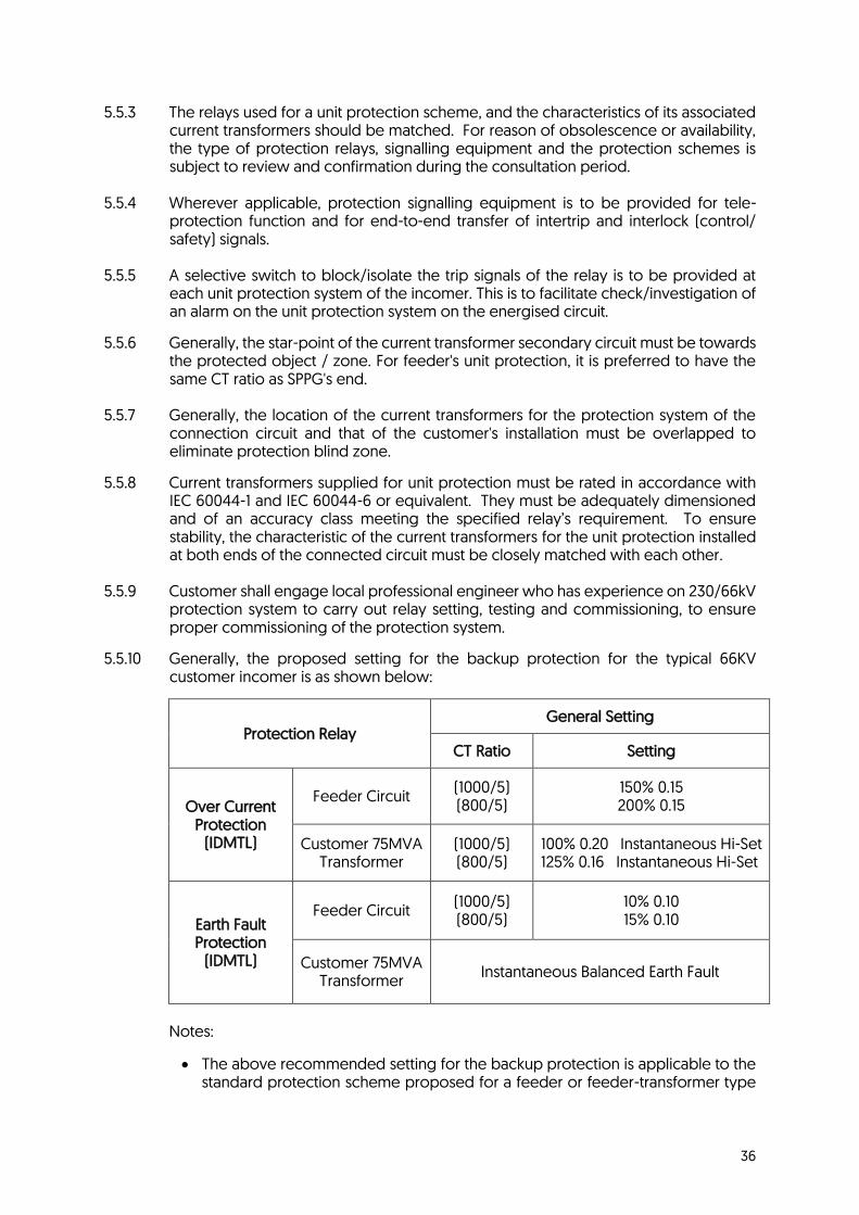
36
5.5.3 The relays used for a unit protection scheme, and the characteristics of its associated current transformers should be matched. For reason of obsolescence or availability, the type of protection relays, signalling equipment and the protection schemes is subject to review and confirmation during the consultation period.
5.5.4 Wherever applicable, protection signalling equipment is to be provided for tele-
protection function and for end-to-end transfer of intertrip and interlock (control/ safety) signals.
5.5.5 A selective switch to block/isolate the trip signals of the relay is to be provided at
each unit protection system of the incomer. This is to facilitate check/investigation of an alarm on the unit protection system on the energised circuit.
5.5.6 Generally, the star-point of the current transformer secondary circuit must be towards the protected object / zone. For feeder's unit protection, it is preferred to have the same CT ratio as SPPG's end.
5.5.7 Generally, the location of the current transformers for the protection system of the
connection circuit and that of the customer's installation must be overlapped to eliminate protection blind zone.
5.5.8 Current transformers supplied for unit protection must be rated in accordance with IEC 60044-1 and IEC 60044-6 or equivalent. They must be adequately dimensioned and of an accuracy class meeting the specified relay’s requirement. To ensure stability, the characteristic of the current transformers for the unit protection installed at both ends of the connected circuit must be closely matched with each other.
5.5.9 Customer shall engage local professional engineer who has experience on 230/66kV protection system to carry out relay setting, testing and commissioning, to ensure proper commissioning of the protection system.
5.5.10 Generally, the proposed setting for the backup protection for the typical 66KV customer incomer is as shown below:
Protection Relay General Setting
CT Ratio Setting
Over Current Protection
(IDMTL)
Feeder Circuit (1000/5) (800/5)
150% 0.15 200% 0.15
Customer 75MVA Transformer
(1000/5) (800/5)
100% 0.20 Instantaneous Hi-Set 125% 0.16 Instantaneous Hi-Set
Earth Fault Protection
(IDMTL)
Feeder Circuit (1000/5) (800/5)
10% 0.10 15% 0.10
Customer 75MVA Transformer
Instantaneous Balanced Earth Fault
Notes:
• The above recommended setting for the backup protection is applicable to the standard protection scheme proposed for a feeder or feeder-transformer type

37
customer connection and is applicable to radial feed connection only. (Appendix 17)
• Customer incomer shall install 'instantaneous' Overcurrent Hi-Set and instantaneous Balanced Earth Fault protections to protect its own transformer.
• The overcurrent and earth fault setting are subjected to periodic review by
SPPG.
5.6 Information on SPPA Network Earthing System for 230kV, 66kV and 22kV
5.6.1 Where customer is connected directly to SPPA’s network, customer shall note the following earthing system at each voltage level.
(a) 230kV - Solidly earthed system
(b) 66kV - Resistive earthed system with neutral ground resistor (NGR) of 19.5 ohms
(c) 22kV - Resistive earthed system with neutral ground resistor (NGR) of 6.5 ohms
5.6.2 Customer shall ensure that all equipment including CTs, VTs, and protection systems
connected to SPPA network meet the technical specification required for the respective earthing system in accordance with the relevant standards.

38
6. Metering Requirements
6.1 General
6.1.1 All metering requirements must comply with EMA’s Metering Code. SPPG will determine the location where the supply line terminates in the premises, based on ease of accessibility to SPSL and SPPG personnel.
6.1.2 The electricity meters are owned, supplied and maintained by SPPA. The “Owner” (developer
of the estate / estate manager / MCST / HDB upgrading contractors / Town Councils or customer) owns and bears the cost of providing and maintaining the meter boards, miniature circuit breakers (MCBs), isolators and wiring for the installation of meters. For “Owners” who also install meter box, they are to provide the product datasheet for the meter box indicating the IP ratings that ensure the UV-resistance and weather-hardiness of the meter box to withstand the local weather conditions in Singapore. For meter box found at HDB flat units, “Owners” are to provide the meter box datasheet from HDB as per their design specifications. This would apply for upgrading or re-wiring that will affect position / wiring of the electricity meter.
6.1.3 Meters can be mounted on any of the following types of meter boards:
(a) Teak board or any hardwood board chemically treated against attacks by termites and is
resistant to moisture and heat. The material should not warp easily. Plywood or fibreboard is not allowed. The meter board must be at least 20mm thick and rigidly fixed with a minimum of 4 fixing screws.
(b) Metal panel with nylon inserts accurately positioned to accommodate the meter.
(c) Glass reinforced polyester base fitted with nylon inserts accurately positioned to
accommodate the meter.
If the meter is house in an enclosure (meter box / meter compartments / riser ducts / cupboard etc), the depth (from surface of meter board) to the surface of the enclosure door must be at least 200mm or greater.
6.1.4 The LEW must ensure that all metering requirements are complied with, and submit, at the
planning stage, all relevant drawings on meter locations, meter board size, meter rooms, meter compartments / riser ducts / cupboard / boxes, etc to Electrical Meters Section for approval. Sample units of each approved type of meter compartment / riser duct / cupboard / box and meter board must be provided for final inspection and approval by Electrical Meters Section before meters are installed. An undertaking letter must be provided by owners of meter boxes, indicating the requirement for the owners to make good and repair the full meter boxes due to damages arising for misuses, vandalism and materials deterioration beyond the usual period of warranty for the new meter boxes.
No payment is required for normal meter installation. For other metering services that are
chargeable, the payment methods below are accepted:
6 Metering Requirements

39
(a) Via cheque made payable to SP PowerAssets Ltd at Electrical Meters Section office
(b) Via bank transfer to SP PowerAssets Ltd
6.1.5 All access doors to meter rooms / compartments / riser ducts / cupboards, etc must be fitted with doorknobs or handles and the doors opening width must be of at least the following:
(a) 600mm width for meter rooms (b) 500mm width for meter riser ducts (c) 450mm width for meter compartment / cupboards
These doors must be able to be opened without the need to use a key or other devices / tools.
6.1.6 If the access doors (as per 6.1.5) are to be locked, they must be fitted with locksets which can
be opened with one of the following master keys:
(a) Abloy master key code reference MK 911047
(b) Chubb (Union) master key code reference G1HBG
(c) Yale master key code reference MK48
Any non-compliance will be rejected during new meter installation compliance checks and developer/contractor, etc would have to arrange for rectification.
6.1.7 Security access systems installed in any premises must not impede access by SPSL and SPPG personnel.
6.1.8 The developer or customer to ensure access to meters must not be obstructed at all times for
SPSL and SPPG personnel to carry out meter reading and maintenance works.
6.1.9 For installations with PV systems (for LT customer), bi-directional meter will be installed if customer is eligible for net settlement purposes.
6.2 Location of Meter
6.2.1 The service board accommodating SPPA's service MCBs and meters must be located near the termination of the service line. The meter / service position must be easily accessible at all times to SPSL and SPPG personnel for maintenance and reading of meters.
6.2.2 Meters must be installed in a safe location with adequate working space where they will not
be damaged or be a cause of danger to personnel (viz, in a clean and dry location, not exposed to weather, mechanical damage, vibrations, extremes of temperature or dampness, away from traffic hazards).
6.2.3 The meter board must be mounted such that the height of the meter register must be between
0.8m and 1.8m above ground level, and the depth of the compartment for installation of meters must be between 200mm and 300mm.
6.2.4 If the meter is inside an enclosure (compartment / cupboard / duct / riser etc.) with an access
door - the depth measured from the meter board surface to the access door must be between 200mm to 300mm. Premise / account owner are to rectify if non-compliant to ensure maintenance (replacement / installation) of meter is not hindered.

40
6.3 Grouping of Meters
6.3.1 Meters must be installed outside each tenant unit for ease of meter reading, maintenance, etc. Where this is not possible for practical reasons, meters may be grouped together in easily accessible centralised meter rooms or meter compartments / riser ducts / cupboards in multi-metered premises (e.g., residential, office, shopping or industrial high-rise building / complex).
6.3.2 Meters in Meter Compartments / Cupboards
(a) Meters are to be grouped on the same floor as the tenant units.
(b) There may be more than one group metering location on each floor.
(c) There must be adequate lighting in the group meter location to facilitate meter
installation / maintenance and meter reading.
(d) Meter boards in meter compartments / cupboards must be such that meters can be mounted facing the doors.
(e) The meter board must be mounted at a height and depth as stated in Section 6.2.3.
(f) All meter compartments / cupboards where meters are installed are to be clearly and permanently labelled. Tenant unit numbers must be engraved or embossed on metal or plastic material and firmly riveted or screwed onto their respective meter board.
(g) Meter compartments / cupboards housing the meters must have clear viewing windows provided on the doors, if these are locked, for ease of meter reading. The clear viewing window must not be less than 200mm (W) x 300mm (H) x 6mm (thickness) and must be correctly positioned in front of where the meter is to be installed. Full glass doors are not acceptable.
6.3.3 Meters installed in Meter Box
(a) Meters must be installed inside a weather hardened and UV-resistant meter box and
easily accessible to SPSL and SPPG personnel.
(b) A clear transparent viewing window of at least 100 mm (W) X 120 mm (H) shall be provided and must be positioned in front of where the meter is to be installed.
(c) There must be at least three hinges connecting the meter box base and the cover. The
hinges for the meter box must be made of good quality.
(d) The keyless lock, if any, shall be made of a rust-resistant material.
(e) The interior of the meter box should be at least 260 mm (H) X 230 mm (W) with a depth of at least 200 mm (D) with a base fitted with nylon inserts accurately positioned to accommodate the meter.
(h) Unit numbers must be engraved or embossed on metal or plastic material and firmly
riveted or screwed onto respective meter board.
6.3.4 Meters in Riser Ducts
(a) Meters are to be grouped on the same floor as the tenant units.
(b) There may be more than one group metering location on each floor.
(c) There must be adequate lighting in the group meter location to facilitate meter installation / maintenance and meter reading.

41
(d) Meter boards in meter riser duct must be mounted such that meters must be facing the
doors.
(e) All meter riser ducts where meters are installed are to be clearly and permanently labelled. Tenant unit numbers must be engraved or embossed on metal or plastic material and firmly riveted or screwed onto respective meter board.
(f) The depth measured from the meter board surface to the riser access door must not be less than 200mm. There must be adequate standing space provided to facilitate meter reading, installation and maintenance work.
(g) If there is slope built on the ground of the meter riser duct which made the riser duct
inaccessible, the depth measured from the meter board surface to the riser access door must be between 200mm to 300mm.
6.3.5 Meters in Centralised Meter Rooms
(a) The height of the meter board or panel must be such that meters can be mounted with
the highest row of the meter register not exceeding 1.8m above floor level and the lowest row not less than 0.8m above floor level.
(b) There must be standing space of at least 600mm in front of the meter panel. However, if the meters are mounted on a free-standing panel, a clearance of 600mm all-round panel is required.
(c) The meter board or panel must be rigidly and vertically mounted. The doors of the panel must be hinged.
(d) Unit numbers must be engraved or embossed on metal or plastic material and firmly
riveted or screwed onto respective meter board.
(e) The meter room must not be used as a storeroom. 6.3.6 Meters Installed in Landed Properties
(a) The meters and service cables must be installed in a weatherproof compartment located
at the gate pillar or perimeter wall. For supply capacity up to 100A 3–phase, the technical requirements for this compartment are as given in Appendix 24. For supply capacity greater than 100A 3-phase where a CT-operated meter will be installed, the LEW has to submit the technical requirements to Electrical Meters Section for approval.
(b) If there is no gate pillar or fencing around the perimeter of the landed properties, meters must be installed inside a weatherproof meter box / compartment and easily accessible to SPSL and SPPG personnel. Meters must not be installed inside the house.
(c) Concrete or hinged galvanised steel grating must be provided in front of the meter compartment mounted at gate post / pillar if a drain exists.
(d) The meter board must be mounted at a height and depth as stated in Section 6.2.3.
(e) Unit numbers must be engraved or embossed on metal or plastic material and firmly
riveted or screwed onto respective meter board.
6.3.7 Meters Installed in Over-Ground Box
(a) Meters must be installed inside a weatherproof meter box / compartment and easily accessible to SPSL and SPPG personnel.

42
(b) Provision shall be made to prevent any stagnation of water within the compartment. Sufficient ventilation shall be provided to avoid high humidity and condensation within the meter compartment.
(c) There must be adequate safe standing space of at least 600mm in front of the meter panel to facilitate meter reading, installation and maintenance work.
6.4 Meter Service Board Specifications (Single-Phase and 3-Phase Services, not Exceeding 100A per Phase)
6.4.1 The meter/service board for SPPA's service MCBs and meters is specified in Section 6.3 and in
accordance with the drawings in Appendices 25, 26 and 27.
6.5 Wiring, Layout of Meters, MCBs, etc. in Centralised Meter Rooms, Meter Compartments / Riser Ducts / Cupboards
6.5.1 All wiring leading in and out of the group meter location must comply with SS CP5. The
landlord's wiring must be segregated from the tenant's wiring.
6.5.2 Meters are to be mounted together with their associated service MCBs / neutral connectors such that each meter can be visually identified with its associated service MCBs. Each meter position must be clearly labelled according to the tenant unit number. There should be a space of 70mm between vertically mounted meters.
6.5.3 Meters are to be mounted in neat vertical columns and/or horizontal rows.
6.5.4 Service MCBs shall be sealable. MCBs must be clearly labelled according to the tenant units
served. The labelling must also correspond to the labels used for the meters.
6.5.5 All wiring on the meter boards from service MCBs / neutral connectors to the meters and from the meters to the customer's main switches must be neatly run on the surface - horizontally and/or vertically. Multiple-strand flexible-type meter wire is not acceptable.
6.5.6 If the meter is inside an enclosure (compartment / cupboard / duct / riser etc.) with an access
door - the depth measured from the meter board surface to the access door must be between 200mm to 300mm. Premise / account owner are to rectify if non-compliant to ensure maintenance (replacement / installation) of meter is not hindered.
6.5.7 No water meter, gas meter or other facilities shall be placed within the same electricity meter
enclosure (compartment / cupboard / duct / riser etc.) for safety reasons. Where this may not be feasible, the electricity meter must be physically segregated away from them (an impervious piece of concrete slab). For such layout, the LEW has to submit the relevant drawings to the Electrical Meters Section for approval.
6.6 Submission of Layout Plans
6.6.1 The layout of the meter rooms, meter compartments / riser ducts / cupboards together with the meter board drawings and plans of the units served, must be submitted at the planning stage by the LEW for approval by Electrical Meters Section.
6.7 Meters for 3-Phase Low Tension Connection (Exceeding 100A per Phase)
6.7.1 Meters for connections exceeding 100A per phase are operated from metering current transformers and are to be fixed on a pre-wired metering panel on the customer’s main switchboard. However, where the length of the connecting leads are not excessive, the pre-

43
wired metering panel may, with the prior approval of Electrical Meters Section, be wall-mounted away from the main switchboard or in a separate meter room. The pre-wired metering panel with Electrical Meters Section approved type test terminal block, 6A (10kA) 4-pole MCB and metering cables to the busbars and the three metering current transformers, must be provided by the customer. Terminal lugs of ring-type should be used for wiring terminations in the metering panel. Drawings of the pre-wired metering panel may be requested from Electrical Meters Section if required.
6.7.2 Meter Panel Compartment Specifications:
(a) Meter panels must be of mild steel of at least 1.6mm thickness or other materials subject
to approval by Electrical Meters Section.
(b) The panels must be detachable and of a size given in Appendix 28.
(c) The compartments must have a minimum depth of 100mm between cover and base.
(d) There must be openings with appropriate bushing for the meter wires.
(e) The cover must have at least 3 hinges and be able to swing and open out at least 90o.
(f) Facilities for sealing must be provided. Methods of sealing are illustrated in the drawings in Appendix 29.
6.8 Meter Installation Requirements
6.8.1 The LEW or switchboard representative must be present for 3-Phase Low Tension Meter (exceeding 100A per phase) installation.
6.8.2 The switchboard must be complete and securely mounted in its final position before meters
can be installed.
6.8.3 The top of the meter panel must not exceed 2.0m from the ground.
6.8.4 A 50mm x 50mm trunking of metal or other approved material between the switchboard and the meter panel must be provided to house the meter cables if the latter is installed away from the customer’s main switchboard.
6.8.5 A 6.0mm tap-hole plus screw or bolt and nut with washer on each busbar must be provided
to facilitate connection of the voltage cables to the meter voltage coils.
6.8.6 If the meter panel is away from the customer’s main switchboard, sealable 30A HRC fuse for each phase and a sealable 4-pole MCB of 6A 10kA rating must be provided on the front of the switchboard panel near the metering CT enclosure for the protection of the meter voltage wiring. The MCB must be appropriately labelled.
6.8.7 Mounting of metering current transformers must be as follows:
(a) Current transformers must be mounted on jumpers for easy installation.
(b) Bakelite clamps must be provided to secure the meter current transformers in position.
(c) Adequate insulation between the metering current transformers and the busbar must be
provided.
(d) The metering current transformers and meter voltage tap off points must be installed after the incoming connection main protection current transformers.

44
6.9 Current Transformer Enclosure
6.9.1 A rigid enclosure of mild steel plate of thickness not less than 1.6mm must be provided solely for housing the metering current transformers and voltage tap off points. The enclosures must have facilities for sealing. A typical construction of the enclosure is shown in Appendix 30.
6.9.2 The customer is advised to adhere strictly to the dimension of the metering current transformer
enclosure shown in Appendix 30 so that the metering current transformers can be fitted into enclosure without any space constraint. Customer shall made arrangement to modify the enclosure should the dimension fails to meet the requirement.
6.10 High Tension/ Extra-High Tension Metering
6.10.1 The customer is required to provide, install and maintain, at his own expense, current transformers, voltage transformers, a pre-wired metering panel with test blocks, MCBs, pilot lamps and accessories, at his receiving HT/EHT switchboard. These must meet SPPA’s requirements. Drawings of the pre-wired metering panel may be requested from Electrical Meters Section.
6.10.2 All metering current and voltage transformers must be used solely for SPPA's revenue metering
equipment. No other apparatus of the customer is permitted to be connected to such metering current and voltage transformers. However, a voltmeter may be allowed to be connected via a 100 mA fuse (sealable) subject to approval by Electrical Meters Section.
6.10.3 The customer must also provide a metering kiosk to be located close to where the metering
current and voltage transformers are installed, such that the route length of the cables from the current and voltage transformers to the metering kiosk does not exceed 20m. Where this cannot be complied with because of site constraints, the LEW must consult Electrical Meters Section concerning the type and size of cables to be provided and installed by the customer.
6.10.4 The requirements for the kiosk are given in Appendices 31 and 32. The access to the metering
kiosk must be from outside the HT switchroom and fitted with any one of SPPA's approved master lock series as specified in Section 6.1.6.
6.10.5 The customer must provide an appropriate metering panel of a size given in Appendix 33 and
install a 50mm x 50mm trunking of metal or other approved material between the customer’s HT switchboard and the metering panel together with the required type and size of cables.
6.10.6 Facilities for sealing connections of all metering wire termination at the customer's HT
switchboard must be provided.
6.10.7 A schematic and wiring diagram of the customer’s switchboard must be supplied to facilitate installation of the meters.
6.11 Specifications for Metering Current Transformers
6.11.1 The customer will provide two metering current transformers of 30VA burden for 66kV connection or 15VA burden for connection at 6.6kV or 22kV. These must be of accuracy class 0.5 complying with IEC 61869-2.
6.11.2 The current transformers are to be installed on the L1 and L3 phases at the cable end for each
of his receiving switchboard. The current transformer ratio will be determined by SPPG based

45
on the customer’s load requirement. For connection at 230kV, the LEW will liaise with Electrical Meters Section on metering requirements.
6.11.3 The rated short-time current rating must not be less than 63kA 1 second, 40kA 3 seconds, 25kA
3 seconds and 20kA 3 seconds for connection at 230kV, 66kV, 22kV and 6.6kV respectively.
6.12 Specifications for Voltage Transformers
6.12.1 For each of the customer’s receiving switchboard, one of the following voltage transformers must be provided:
(a) One unit 3-phase 66kV/110V, 22kV/110V or 6.6kV/110V voltage transformer of 100VA
burden per phase, connected star-star with the L2 phase (yellow phase) terminal of the secondary winding earthed, or
(b) Three units single phase, 66kV 110V or 22kV 110V or 6.6kV 110V
3 3 3 3 3 3
Voltage transformers of 100VA burden per phase, connected star-star with the L2 phase (yellow phase) terminal of the secondary winding earthed.
6.12.2 Voltage transformers must be of accuracy class 1.0 complying with IEC 61869-3. The secondary wiring of the voltage transformer must terminate in a sealable MCB incorporated in the switchgear panel. The MCB must be rated at 6A, 110V, 50Hz with breaking capacity not less than 10kA and the terminals of the MCB must be able to accept cables of cross section up to 6mm2.
6.12.3 The voltage transformers must be fused and adequate stock of spare high-voltage fuses must
be kept by the customer.
6.13 Testing of Metering CTs and VTs’
6.13.1 All metering current transformers together with their manufacturers' test certificates must be submitted for testing and approval by Electrical Meters Section at the Meter Test Laboratory at least 2 weeks before connection. Lead time required for CT testing is 2 weeks.
6.13.2 Original manufacturer test reports of all voltage transformers must be submitted to Electrical Meters Section for approval before the voltage transformers are installed at site. The test reports must be endorsed by an accredited testing laboratory under the SAC-SINGLAS or SAC MUTUAL RECOGNITION ARRANGEMENTS (MRA) partners program. Voltage transformer supplier must produce a declaration letter signed by a Licensed Electrical Worker (LEW) that the voltage transformers have been tested for compliance with IEC 61869-3.
6.13.3 All test certificates and reports mentioned in Section 6.13.1 and 6.13.2 for the metering current transformers and voltage transformers must be submitted through SP Group eBusiness portal.
6.13.4 The metering voltage transformers, after re-installation onto customer’s switchgear, have to be tested and phase out, and a test report (Appendix 34) has to be submitted to Electrical Meters Section for approval before installation of meters.

46
6.14 Miscellaneous Metering Requirements
6.14.1 Low Tension Customer
(a) Single Customer - More than 75kVA
• The customer will provide three metering current transformers (CTs) of 5VA burden and accuracy class 0.5 complying with IEC 61869-2 and the pre-wired metering panels on the customer’s intake switchboard. The pre-wired metering panel must be fitted with SPPA approved type test block, 4-pole MCB and connected with metering cables to the CTs and busbars. The CTs together with their manufacturer’s test certificates must be submitted for testing and approval at least 2 weeks before connection is required.
• A request for appointment to fix meters shall be made only after the LEW has arranged
with SPSL for a date to energise the service connection.
• Electrical Meters Section will arrange to install the meters upon production of the energisation appointment letter issued by SPSL and requires at least 4 business days before the date of energisation of service connection.
6.14.2 Multi-Metered Buildings
(a) Submission of floor plans of building showing the locations of metering kiosks, meter
room, meter compartments / riser ducts / cupboards / boxes.
(b) Submission of dimensioned metering layout showing the plan, front and side elevations of the meter boards / rooms / compartments / riser ducts / cupboards, etc.
(c) Arrangements for sample units of each approved type of meter compartment / riser duct / cupboard / box and meter board to be inspected and approved by Electrical Meters Section before meters are installed.
6.14.3 Landed Housing Development
(a) Submission of site plans of building showing the locations of meter compartment at gate
post / pillar.
(b) Submission of dimensioned metering layout showing the plan, front and side elevations of the meter compartment in the gate post / pillar.
(c) Arrangements for sample units of each approved type of meter compartment and meter board to be inspected and approved by Electrical Meters Section before meters are installed.
6.14.4 High Tension / Extra-High Tension Customer
(a) The revenue metering equipment will be installed at the customers’ end of the service
connection. The customer shall provide a suitable metering kiosk at his intake station, and metering CTs and VTs for each of his receiving switchboard.
(b) Remote meter reads will be performed by means of Advance Metering Infrastructure
(AMI) radio frequency network where AMI meters will be installed at high tension / extra-high tension customer’s premises.
(c) The LEW shall propose suitable metering CTs with ratios to cater for the contracted capacity and the ultimate load subject to approval by Electrical Meters Section. The table below is provided as a guide:

47
Customer Connection Contracted Capacity (MW) CT Ratio
22kV
Service Connection
0.0 - 0.8 50/25/5
0.81 - 1.7 100/50/5
1.71 - 2.5 150/75/5
2.51 - 3.2 200/100/5
3.21 - 5.0 300/150/5
5.01 - 6.6 400/200/5
6.61 - 10.0 500/300/5
66kV
Service Connection
0.0 - 5.0 100/50/5
5.01 - 10.0 200/100/5
10.01 - 20.0 400/200/5
20.01 - 30.0 500/300/5
30.01 - 40.0 800/400/5
40.01 - 80.0 1000/500/5
(d) For installations that use metering VT with two or more separate windings, LEW may request the Letter of Undertaking from Electrical Meters Section.
6.15 Contestable Customers
6.15.1 Eligibility
(a) The eligibility of contestable customers is determined by EMA.
6.15.2 Additional Requirements for Contestable Customers on AMI Meters
(a) A contestable customer using Advanced Metering Infrastructure (AMI) meters based on RF shall, in the event that RF signal is weak at the metering point, facilitate and get approval from the building owner for SPPG to install additional Radio Frequency (RF) infrastructure from the meter to the RF antenna. The scope of work shall be advised by SPPG after site assessment. RF infrastructure shall include but not limited to the following items:
i. RF High Gain Antenna ii. Coaxial cable iii. Termination box iv. Other associated materials
If the contestable customer is a tenant, they must obtain prior approval from their landlord for such works to be carried out.
(b) If the RF infrastructure is not feasible, the contestable customer shall facilitate, together
with the building owner - the installation of Telco infrastructure to ensure the availability of mobile telecommunication coverage where the metering point is located. Customer shall co-ordinate with SPPG for such scenarios.
6.15.3 Additional Requirements for Contestable Customers on MV90 Meters
(a) Existing contestable customers on MV90 meters are strongly encouraged to replace the
MV90 meters to AMI meters which uses RF network for remote meter reading.
(b) The customer or their LEW representative can contact Electrical Meters Section to arrange for MV90 meter replacement to AMI meter.

48
6.16 Maintenance Procedure
6.16.1 High Tension and Low Tension Supply with Capacity above 69kVA
(a) All customers or their LEW representative shall write in to Electrical Meters Section to seek approval for any works that will require them to break SPPG metering seals for maintenance or any other purposes. Customers are to state in details the scope of works and are not allowed to break the seals prior to approval from Electrical Meters Section.
(b) Upon approval from Electrical Meters Section to break seal, customer or their LEW
representative shall take photographs of the SPPG metering seals before and after breaking with the serial number of the seals clearly visible and submit to Electrical Meters Section.
6.16.2 Supply Capacity up to 69kVA
(a) For any work that requires breaking of metering seals, the LEW shall submit application to SP Services Ltd.

49
7. Appendices
7 Appendices

50
Appendix 1
LETTER OF CONSENT FOR SUBMISSION OF APPLICATION FOR ELECTRICITY SUPPLY Note: 1) Submission of the letter of consent as part of the supporting documents is compulsory during CS 1 and CS 5 online application submission. 2) The owner of the premise has to indicate that prior consent has been given to the Licensed Electrical Worker to submit applications on his/her behalf. 3) Similarly, the Licensed Electrical Worker has to acknowledge that he has been granted consent to submit the application on behalf of the owner. 4) A copy of the letter of consent is available on SP Services webpage for download under the Licensed Electrical Worker tab. A sample copy is attached.

51
Appendix 3 FORM CS/3
Letter of Consent from the Landlord/Management Corporation To: SP Group Email: [email protected] 2 Kallang Sector Singapore 349277 Attn: SP Services
ELECTRICITY SUPPLY TO _______________________________________________________________________ (Full Address of the Customer)
FOR _____________________________________________________________________________________ (Name of Customer)
TOTAL LOAD ALLOWED FOR: ______________________________ AT __________________________VOLTS
_____________________________________________________________________________________
PART I 1. I have checked the loading of the electrical installation of the abovementioned building/complex and hereby confirm
that the abovementioned load requirement can be catered for from the rising/horizontal mains system/main switchboard of the building/complex, and the total approved load to the entire building/complex will not be exceeded.
2. I have no objection for the abovementioned load to be connected to the rising/horizontal mains system/main
switchboard of the building/complex. 3. The Electrical Installation Licence No. of the building/complex is ______________________. 4. The electrical installation of the building/complex from which this load is to be connected is Unmetered (i.e. without Master Account) Metered under Master Account No. ________________________. 5. I will check to ensure that the abovementioned installation is compatible with the electrical installation of the
building/complex. _____________________________________ Date: _____________________ Signature of Licensed Electrical Worker Licence No: _____ /___________ Tel No: _____________________ Name: ______________________________________ Address: ______________________________________________________________________________ ______________________________________________________________________S(_____________)
PART II I hereby give consent for the abovementioned customer to tap electricity supply of a capacity indicated above from the rising/horizontal mains system/main switchboard of the building/complex. ___________________________________ Date: _____________________ Signature of Authorised Person __________________________________________ _________________________ Name Designation Official Stamp of the Landlord/Developer/Management Corporation 13/10/11

52
Appendix 4
FORM CS/3H Letter of Consent from Housing & Development Board
To: SP Group Email: [email protected] 2 Kallang Sector Singapore 349277 Attn: SP Services
ELECTRICITY SUPPLY TO ______________________________________________________________________ (Full Address of the Customer)
FOR ________________________________________________________________________________ (Name of Customer)
TOTAL LOAD ALLOWED FOR: ___________________________ AT ____________________VOLTS
____________________________________________________________________________
PART I 1. I have checked the loading of the electrical installation of the above-mentioned building/complex and hereby confirm
that the above-mentioned load requirement can be catered for from the rising/horizontal mains system/main switchboard of the building/complex, and the total approved load to the entire building/complex will not be exceeded.
2. I have no objection for the above-mentioned load to be connected to the rising/horizontal mains system/main
switchboard of the building/complex. 3. The Electrical Installation Licence No. of the building/complex is __________________________. 4. The electrical installation of the building/complex from which this load is to be connected is: Unmetered (i.e. without Master Account) Metered under Master Account No. ________________________. 5. I will check to ensure that the above-mentioned installation is compatible with the electrical installation of the
building/complex. _______________________________________ Date: _________________________ Signature of Licensed Electrical Worker Licence No.: _____ /___________ Tel No.: _________________________ Name: __________________________________ Address: _____________________________________________________________________ _____________________________________________________________S(_____________)
PART II I hereby give consent for the above-mentioned customer to tap electricity supply of a capacity indicated above from the rising/horizontal mains system/main switchboard of the building/complex. _______________________________________ Date: _________________________ Signature of Authorised Person For and on behalf of Housing & Development Board __________________________________ _____________________________ Name Designation Official Stamp of the Landlord/Developer/Management Corporation 19/10/11

53
Appendix 5
REQUEST TO HANDOVER SUBSTATION
Date: To: SP Group
2 Kallang Sector Singapore 349277 Attn: SP PowerGrid (CPW / CPE / DNP)
Dear Sir PROJECT: ELECTRICITY SUPPLY TO ________________________________________________
1. In connection with the electrification scheme (SPSL Appln No: ________________), I wish to advise that the proposed SPPA substation has been completed in accordance with plans and specifications approved by your Company and the Competent Authority. 2. I confirm that the structural Professional Engineer in-charge has certified that the substation structure is constructed according to the approved plan to withstand the load specified by your Company. 3. I also certify that the electrical installation at the substation has been inspected and tested in accordance with the requirements of your Company as follows:
a Earth value of electrode system is ______________ ohms. b The continuity of each circuit protective conductor is satisfactory. c All metal conduits have been bonded to earth.
d Polarity throughout the installation is correct. e All single pole control devices are in live conductors only. f The insulation resistance of the fixed wiring installation is ___________ Megaohm. g All flexible cords, switches, fuses, plugs and socket outlets are in good serviceable condition.
h The installation includes ______________ Nos lighting points and _______________ Nos socket outlets. 4. I shall be obliged if you could send your representative for a joint site inspection on _____________________, and thereafter to takeover the said substation.
Yours faithfully
_________________________________ Signature of Licensed Electrical Worker
Name: _______________________________________________________________________ Address: _______________________________________________________________________
Tel No: _______________________________________________________________________ NB: This form must be submitted one week prior to the date for joint site inspection, which shall normally
take place from 10 am to 12 noon.

54
Appendix 6 – Pg 1

55
Appendix 6 – Pg 2

56
Appendix 7

57
Appendix 9
TYPES AND LAYOUT OF SUBSTATION
The type of substation required will depend on the customer's load requirement. SPSL shall endeavor to provide the requirement of the substation within 10 business days following the receipt of application form. Example of typical layout plans and details for substations of the independent building type are given in Appendices 11 to 15. As a guide, the types of substations applicable for the various load requirements are as follows: -
Load Requirement Primary Distribution Voltage
Room Size (M)
L x W x H Drawing References
Up to 1,000 kVA at 400/230V 22kV Switchroom: 6.0 x 5.7 x 5.6
Transformer: 4.0 x 4.5 x 3.6
Up to 2,000 kVA at 400/230V 22kV Switchroom: 7.0 x 6.7 x 5.6
Transformer: 6.7 x 4.5 x 3.6
Appendices 11
Up to 4,250 kW at 22kV 22kV Switchroom: 6.0 x 6.2 x 5.6
Up to 12,750 kW at 22kV 22kV Switchroom: 9.3 x 6.2 x 5.6
The functional and safety requirements inclusive of the Workplace Safety and Health (Work at Height) Regulations 2013 & Amendment Regulations 2014 for the substation must be complied with. For example, the minimum clear height of paved vehicular access shall be 4.5m (1-storey), and 5.5m (1½-storey) for the delivery area directly in front of the substation. Subject to the layout and access being suitable, the customer may incorporate the substation as part of his main
building. The typical layout plans shown in this handbook depict only the functional requirements.

58
Appendix 10
SUBMISSION OF SUBSTATION SITE AND LAYOUT PLANS
Before construction of the substation, the LEW shall submit to SPPG, 2 sets of plans showing all relevant information for vetting. These include (a) site / location of the proposed substation in relation to the rest of the development, (b) detailed plans layout, (c) sections and elevations, (d) electrical layout c/w single-line drawing, and (e) all relevant miscellaneous details. Upon approval, one set of endorsed plans shall be returned to LEW.
All plans/drawings are to be submitted in A1 or A2 size paper. All pages are to be signed by the LEW who is responsible for the planning and design of the proposed substation. To facilitate processing, LEW covering letter should include SPPG and MWP references, Project title and name / contact number of his engineer-in-charge. “Checklist for Submission of Substation Plans (Appendix 14) should also form part of the plans submission.
In the case of plans re-submission, all amendments (addition/deletion/revision) must be highlighted in the new set of drawings and listed out in the covering letter.
All plans are to be drawn to scale (1:50 for main layout, 1:100 for sections, elevations, etc) with total dimensions and breakdown dimensions/all spacing shown clearly. Alternative Electronic e-submission: In line with current trend, submission in digital format has been accepted as an alternative format. Sequential layout format as the conventional (manual) version similarly applies. Comments and replies shall be offered digitally via e-mail. The e-mail addresses dedicated for the respective zone for submission are listed as follows :-
i) [email protected] (East Zone) ii) [email protected] (West Zone)
Substation Site Plans
These plans should show the location of the proposed substation(s) in relation to the surrounding area and should include the following:
1 The proposed substation(s) – to be highlighted 2 Customer’s intake switchroom(s) (“CSR”) and service cable route/set-up to substation; 3 SPPA’s main incoming cable entry with sectional details inclusive of roadside drain top/invert level on layout plan 4 SPPA’s main incoming cable entry with sectional details inclusive of roadside drain top/invert level on layout plan 5 Access driveway width, finish & headroom, where applicable including highlighting it up to development’s entrance to public road 6 North-East Gridlines or 2 NE survey coordinates. 7 Endorsement Block : complete with MWP Reference No., Applied load at specific voltage level, CSR
location (level), onus on party to provide/ install/ maintain service cables, Target date of energization. 8 Development Title and address
Substation Design/Layout Plans
It is mandatory that the submission shall include the following:
1 Salient requirements for the design of the substation are as listed in Appendix 15. Unless explicit waiver is granted, these requirements are to be incorporated in the architectural and structural plans 2 Plan, front, rear and side elevations with at least 3 cross sections showing the surrounding roads, cable chamber, switch room beams and clear height, switch room floor openings, transformer plinths, trenches and other pertinent details; 3 Space usage of adjoining upper floor, basement as well as adjacent spaces surrounding the substation shall be stated if substation forms part of the owner’s building. 4 An AutoCAD softcopy of the endorsed substation site/location shown within the overall development as shown on the site/location plans to be emailed to our Singapore Power Infocomm Technology Department to [email protected] to facilitate our digitization in our mapping system. Important Note: It is the onus of the LEW in charge to liaise with the project architects and structural engineers to ensure that all requirements as endorsed on the drawings are incorporated in the architectural and structural plans prior to the commencement of the substation construction.
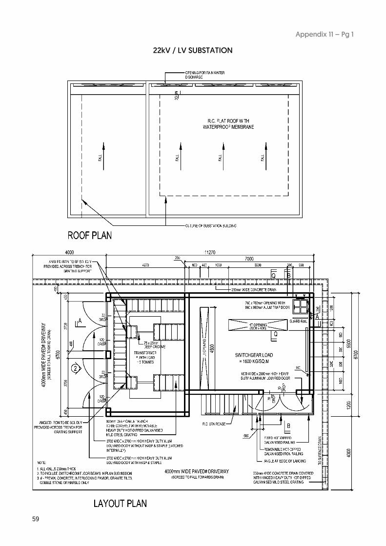
59
Appendix 11 – Pg 1
22kV / LV SUBSTATION

60
Appendix 11 – Pg 2
22kV / LV SUBSTATION

61
Appendix 11 – Pg 3
22kV / LV SUBSTATION
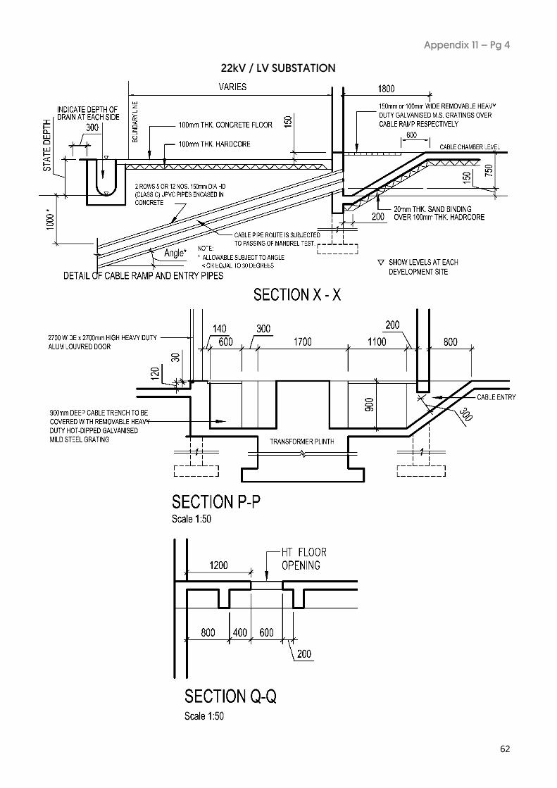
62
Appendix 11 – Pg 4
22kV / LV SUBSTATION

63
Appendix 11 – Pg 5
22kV / LV SUBSTATION
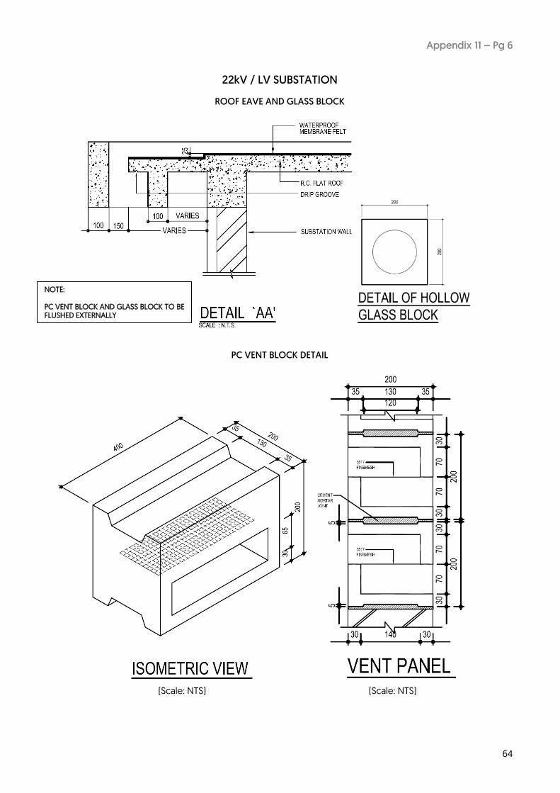
64
Appendix 11 – Pg 6
22kV / LV SUBSTATION
ROOF EAVE AND GLASS BLOCK
PC VENT BLOCK DETAIL
NOTE: PC VENT BLOCK AND GLASS BLOCK TO BE FLUSHED EXTERNALLY
(Scale: NTS) (Scale: NTS)

65
Appendix 11 – Pg 7
22kV / LV SUBSTATION
DETAILS OF RAILINGS (FIXED / REMOVABLE)

66
Appendix 11 – Pg 8
22kV / LV SUBSTATION
TRENCH AND GRATINGS
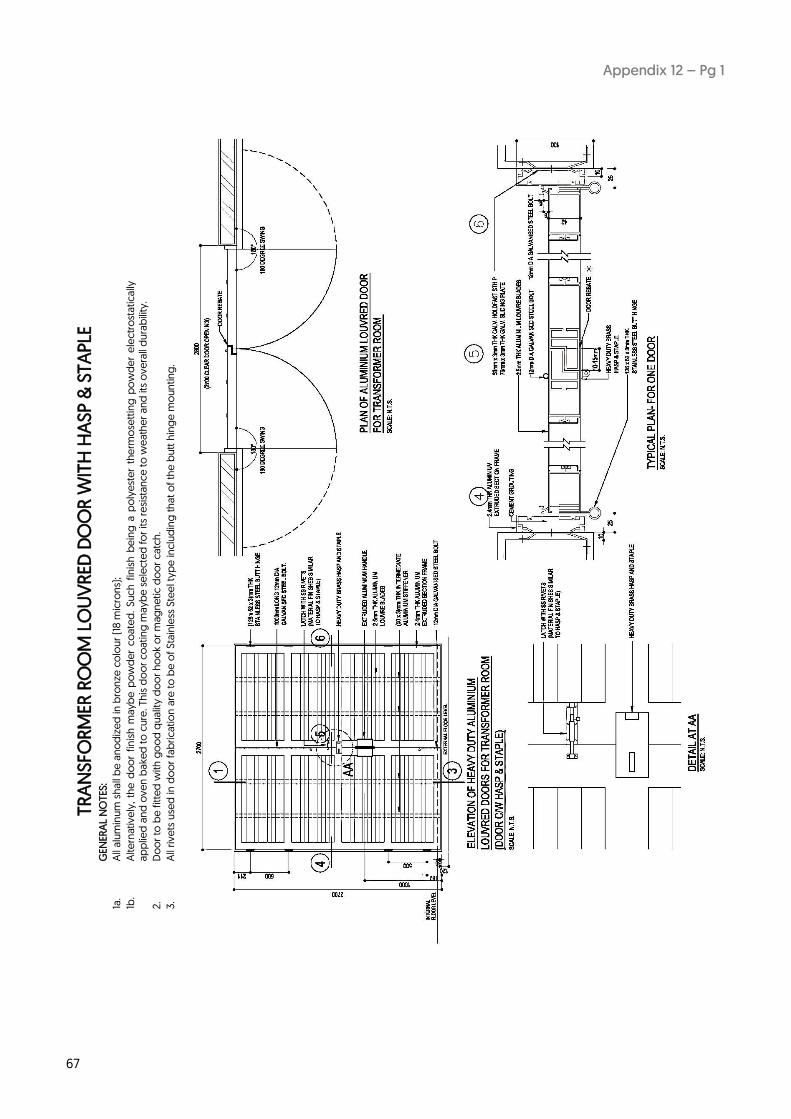
67
Appendix 12 – Pg 1
TR
AN
SFO
RM
ER R
OO
M L
OU
VR
ED D
OO
R W
ITH
HA
SP &
STA
PLE
G
ENER
AL
NO
TES:
1a.
All
alu
min
um
sh
all
be
an
od
ize
d in
bro
nze
co
lou
r (1
8 m
icro
ns)
;
1b.
Alte
rnat
ive
ly,
the
do
or
fin
ish
ma
ybe
po
wd
er
co
ate
d.
Su
ch
fin
ish
be
ing
a p
oly
est
er
the
rmo
sett
ing
po
wd
er
ele
ctr
ost
atica
lly
ap
plie
d a
nd
ove
n b
ake
d t
o c
ure
. Th
is d
oo
r co
atin
g m
ayb
e s
ele
cte
d f
or
its
resi
sta
nc
e t
o w
ea
the
r a
nd
its
ov
era
ll d
ura
bili
ty.
2.
Do
or
to b
e f
itte
d w
ith g
oo
d q
ua
lity
do
or
ho
ok
or
mag
ne
tic d
oo
r ca
tch
.
3.
All
rive
ts u
sed
in d
oo
r fa
bri
ca
tio
n a
re t
o b
e o
f Sta
inle
ss S
tee
l ty
pe
inclu
din
g t
ha
t o
f th
e b
utt
hin
ge
mo
un
ting
.
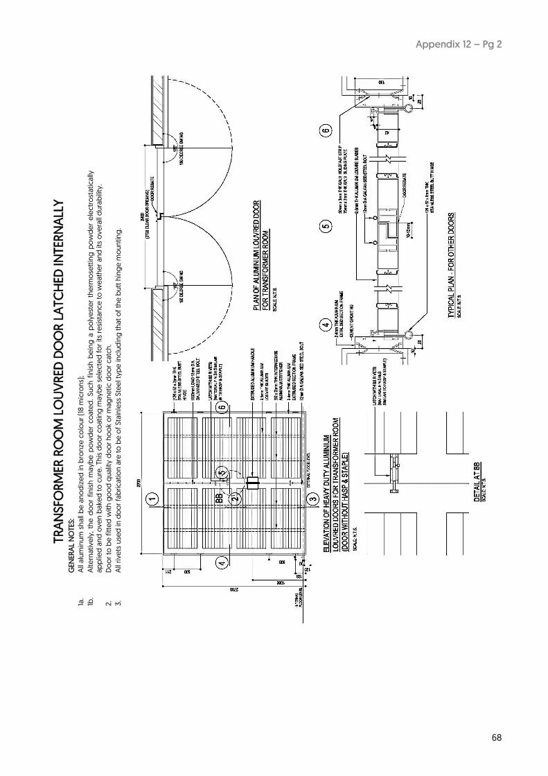
68
Appendix 12 – Pg 2
TR
AN
SFO
RM
ER R
OO
M L
OU
VR
ED D
OO
R L
ATC
HED
INTER
NA
LLY
G
ENER
AL
NO
TES:
1a.
All
alu
min
um
sh
all
be
an
od
ize
d in
bro
nze
co
lou
r (1
8 m
icro
ns)
;
1b.
Alte
rnat
ive
ly,
the
do
or
fin
ish
ma
ybe
po
wd
er
co
ate
d.
Su
ch
fin
ish
be
ing
a p
oly
est
er
the
rmo
sett
ing
po
wd
er
ele
ctr
ost
atica
lly
ap
plie
d a
nd
ove
n b
ake
d t
o c
ure
. Th
is d
oo
r co
atin
g m
ayb
e s
ele
cte
d f
or
its
resi
sta
nc
e t
o w
ea
the
r a
nd
its
ov
era
ll d
ura
bili
ty.
2.
Do
or
to b
e f
itte
d w
ith g
oo
d q
ua
lity
do
or
ho
ok
or
mag
ne
tic d
oo
r ca
tch
.
3.
All
rive
ts u
sed
in d
oo
r fa
bri
ca
tio
n a
re t
o b
e o
f Sta
inle
ss S
tee
l ty
pe
inclu
din
g t
ha
t o
f th
e b
utt
hin
ge
mo
un
ting
.

69
Appendix 12 – Pg 3
SWIT
CH
GEA
R L
OU
VR
ED D
OO
R
GEN
ERA
L N
OTE
S:
1a.
All
alu
min
um
sh
all
be
an
od
ize
d in
bro
nze
co
lou
r (1
8 m
icro
ns)
;
1b.
Alte
rnat
ive
ly,
the
do
or
fin
ish
ma
ybe
po
wd
er
co
ate
d.
Su
ch
fin
ish
be
ing
a p
oly
est
er
the
rmo
sett
ing
po
wd
er
ele
ctr
ost
atica
lly
ap
plie
d a
nd
ove
n b
ake
d t
o c
ure
. Th
is d
oo
r co
atin
g m
ayb
e s
ele
cte
d f
or
its
resi
sta
nc
e t
o w
ea
the
r a
nd
its
ov
era
ll d
ura
bili
ty.
2.
Do
or
to b
e f
itte
d w
ith g
oo
d q
ua
lity
do
or
ho
ok
or
mag
ne
tic d
oo
r ca
tch
.
3.
All
rive
ts u
sed
in d
oo
r fa
bri
ca
tio
n a
re t
o b
e o
f Sta
inle
ss S
tee
l ty
pe
inclu
din
g t
ha
t o
f th
e b
utt
hin
ge
mo
un
ting
.

70
Appendix 12 – Pg 4
SWIT
CH
GEA
R A
ND
CA
BLE
CH
AM
BER
EX
IT D
OO
R
GEN
ERA
L N
OTE
S:
1a.
All
alu
min
um
sh
all
be
an
od
ize
d in
bro
nze
co
lou
r (1
8 m
icro
ns)
;
1b.
Alte
rnat
ive
ly,
the
do
or
fin
ish
ma
ybe
po
wd
er
co
ate
d.
Su
ch
fin
ish
be
ing
a p
oly
est
er
the
rmo
sett
ing
po
wd
er
ele
ctr
ost
atica
lly
ap
plie
d a
nd
ove
n b
ake
d t
o c
ure
. Th
is d
oo
r co
atin
g m
ayb
e s
ele
cte
d f
or
its
resi
sta
nc
e t
o w
ea
the
r a
nd
its
ov
era
ll d
ura
bili
ty.
2.
Do
or
to b
e f
itte
d w
ith g
oo
d q
ua
lity
do
or
ho
ok
or
mag
ne
tic d
oo
r ca
tch
.
3.
All
rive
ts u
sed
in d
oo
r fa
bri
ca
tio
n a
re t
o b
e o
f Sta
inle
ss S
tee
l ty
pe
inclu
din
g t
ha
t o
f th
e b
utt
hin
ge
mo
un
ting
.

71
Appendix 12 – Pg 5
HASP AND STAPLE GENERAL NOTES: 1a. All aluminium shall be anodized in bronze colour (18 microns); 1b. Alternatively, the door finish maybe powder coated. Such finish being a polyester thermosetting powder electrostatically applied and oven baked to cure. This door coating maybe selected for its resistance to weather and its overall durability. 2. Door to be fitted with good quality door hook or magnetic door catch. 3. All rivets used in door fabrication are to be of Stainless Steel type including that of the butt hinge mounting.
ALUMINIUM VENT

72
Appendix 13
GATE DETAILS

73
Appendix 14
CHECKLIST FOR SUBSTATION BUILDING PLAN SUBMISSION
Proposed : __________________________________________
Name of Licensed Electrical Worker (LEW) / Qualified Person (QP) : _____________________
BP No (if any): ______________________________________
ITEMS YES NO
1 Drawings in A1 or A2 series.
2 Plan, front, rear and side elevations included.
3 Cross-sections in relation to roads and immediate surroundings included.
4 Detailed layout scales in 1:50 for all plans and 1:100 for all sections and elevations.
5 Substation requirements stated in Handbook on How to Apply for Electricity
Connection including latest updating are complied with.
6 Plans duly signed by the Licensed Electrical Worker / QP.
7 Proper vehicular access to the substation from main road coloured.
8 I have advised the structural PE that substation structure is to be designed to
withstand the loading specified in the Handbook and all structural requirements
have been reflected in this submission.
9 All trenches/floor openings not affected by any beam.
10 Required clear (from underside of any beam) of all equipment rooms and cable
chamber complied with.
11 No column within substation.
12 No wet area above substation.
13 Location of Customer's Switch room and proposed service cable route shown.
SPPG/ owner (delete as appropriate) to provide service cables.
14 This installation is required to or would like to receive interim supply via mobile
generator.
15 Location of Customer’s LT Switch room / remote connection point for the
connection of mobile generator shown.
16 I undertake to advise the architect and structural PE to ensure that all the
requirements as endorsed, are incorporated into the architectural and structural
plans prior to substation construction
17 Previous drawings with SPPG's comments attached (for resubmission case)
18 All additions / deletions / amendments coloured
19 Any encumbrances? If so, please highlight.
20 Latest edition of Appendix 15 (Notes on Substation Salient Layout Requirements) appended. Latest edition of Appendix 15 (Notes on Substation Salient Layout Requirements)
appended ? _________________________________________ _____________ _________
Signature & Stamp of Licensed Electrical Worker Licence No Date Note: Please tick in appropriate box for all items. This checklist is to be submitted for every submission / re-submission.

74
Appendix 15 – Pg 1
SUBSTATION SALIENT LAYOUT REQUIREMENTS TO BE INCORPORATED IN THE ARCHITECTURAL PLANS
ITEM REQUIREMENT
Location Proposed substation to be located on flood-free area on level above Minimum Platform Level (MPL) as declared by NEA. (LEW to furnish relevant letter from NEA)
Security Access 24/7 unrestricted/unimpeded security access to be provided. Types:
(a) 24-hour manned guard house preferred.
(b) Dedicated access: c/w 1.8m high, 4m wide heavy duty aluminium hollow block gate to standard details. (see Appendix 13 for gate details).
(c) Shared access: to provide gate with dual-locking facility.
(d) Unmanned gate: to provide call panel / intercom facility / CCTV linked to remote 24-hour manned control room.
(e) 24-hour free (unmanned) access: to state, if relevant.
Driveway/Access Road
Width & Finishes: to be of minimum 4.0m wide on “flat” ground. A gradient greater than 1:15 is not acceptable at equipment delivery area in front of the switch room. Surface to be paved with premix/tarmac, concrete, interlocking paviours, granite tiles, cobble stone or marble only. Grasscell or grasscrete as material for driveway finishes is not acceptable.
Loading: To withstand heavy vehicles with laden load of 40 tonnes for all 22kV & 6.6KV substations.
Headroom: 4.5m minimum clear to be maintained throughout the entire route for vehicular passage. Headroom requirement at equipment delivery area (in front of switch room) is 5.5m minimum for 1 ½ -storey type of substation. 4.5m headroom is sufficient for 1-storey substation.
No parking lots are to be drawn in such a way that car parked over them would obstruct vehicular access to the substation.
Cable Entry Ducts Type: Heavy duty (Class C) UPVC pipes of 150mm diameter in concrete jacket to be provided.
(a) Pipe Termination: To be terminated 300mm beyond boundary line or the roadside drain abutting public road at a depth of not exceeding 2.0m from the finished road level. Maximum 2-layer configuration is allowed and is to be laid at an angle not greater than 30 degrees tilting towards the external. All installed pipes to pass through Mandrel Tests prior to inspection by SPPG. (see Appendix 15.1)
(b) Pipe Clearance: To clear 2.5m minimum from any N-Park tree, fire hydrant, manhole, OG Box, lamp post etc. All street furniture are to be clearly shown. Termination of pipes at rigid pavement is not permitted.
Pipe Encasement: All entry pipes within owner’s premises to be encased in concrete jacket, including those installed at high level of basement level. Adequate cable plate of appropriate voltage level covering the width of the encasement installed and laid along the route of the connecting pipes shall be provided. Lead-in pipes on suspended tray/ladder are not permitted.
Pipe Sealant: All entry pipes c/w pulling ropes to be sealed with removable water-tight and gas-tight material at both ends upon installation. Approved compound types are : (i) Viscotaq @ Visco Sealant, (ii) Sealtaq @ Aquablock, (iii) 4416 Duct Sealant Kit 3M, (iv) Densoseal 16A.
(c) Sectional View: Full and detailed sectional view, including draw pit(s) if any, reflecting boundary line, depth of pipes, ground services to be shown.
HDB Precinct Projects:
For new substations, the entire cable entry pipe routing to be provided by developer/HDB.
For upgrading projects, entry pipe provision is under SPPG’s purview except for areas where pipes encroach onto building apron, linkway, special landscaping area, covered walkway, EPS gantry, footpath tiles and drain undercrossing structure.
Non-HDB Projects within HDB Precinct:
For Non-HDB projects, eg. schools and institutions, religious buildings, commercial malls, private condominium, developer is obligated to provide lead-in pipes not just beyond the site boundary, but to the nearest public road if there is no suitable network cables within the precinct from which supply could be tapped.
Letter of Undertaking (LOU)
For lead-in pipe structure overcrossing ENV drain:
(a) Written consent from PUB (Catchment & Waterways Dept (C&WD) ) and design approval by SPPG both to be obtained prior to construction.
(b) Upon approval, a back-to-back LOU to be issued by the developer to SPPG Project Engineer / Officer at time of substation inspection, or earlier.

75
Appendix 15 – Pg 2
Cable Entry Ramp
(a) Avoid being in the way of escape door, areas below switchgear and LT board, if possible.
(b) For service cable connection via cable ramp to CSR, the height clearance shall be capped at 250mm max.
(c) Walls and floors to be plastered, rendered waterproof.
(d) To be sand-filled with washed dry sand and covered with removable heavy duty hot-dipped galvanized mild steel gratings after cable installation.
Cable Trenches (a) Depth: normal trenches within substation for LT board and T/F tails are of depth 900mm. However, for 1-storey type set-up, the “double trench” shall be of depth 1500mm. Cat ladder to be provided within to facilitate access to base of trench.
(b) For service cable connection via cable trench, the height clearance at separation wall shall be capped at 250mm max.
(c) To be sand-filled with washed dry sand and covered by removable heavy duty hot-dipped galvanized mild steel gratings after cable installation.
(d) Grating support: At L– or T–junctions of trench, angle-iron bar (or flat bar) to be solidly provided for grating support. (See details of “grating support”). Grating laid must be able to withstand a minimum load of 100kg.
(e) No beams shall be allowed within / across the trenches.
Draw Pit (a) Sunken type: applicable to area / surface of premix (tarmac) finishes only ; pit to be 800mm below road surface.
(b) Surface or flushed type: easy access to flushed removable covers dispenses the need for excavation; applicable to driveway of paved finishes such concrete, marble, granite tiles, cobbled stone, interlocking paviors and grass. For practical reason, in the case of grass, no part over the exposed pit is allowed for flowering plants or shrubs to be planted. SPPG shall not be held liable for any damage to vegetation rendered by owner over the draw pit in any activities involving pit access.
(c) Weight of pit cover: to be of manageable weight less than 55kg/piece.
(d) Depth: cat ladder to be provided for access to base for all cases when the depth of the pit proper is in excess of 1.5m.
Cable Chamber
”Basement”
(a) Type/Loading: To be of ‘suspended’ type and of floor loading 400kg/m2 minimum.
(b) Floor level drop: 150mm above the external apron / driveway level and be above MPL as declared by NEA.
(c) Headroom clearance: floor-to-floor (switch room to chamber) height difference is to be at least 2m. A minimum headroom of 1.5m from bottom of beam support to finished floor level (FFL) be maintained.
(d) Door: Single-leaf, heavy-duty aluminium solid door of dimension (1.2mW x 1.5mH), complete with door handle and 5 nos. of shoot bolts on internal side (See door details) and restraining door hooks externally.
(e) Warning sign plates: To affix the following:
(i) “No Smoking” sign plate prominently affixed on external side of door.
(ii) “Hard Hat Area” sign plate prominently affixed on chamber wall near cat ladder area.
(f) Warning strip: To paint a 50mm (H) warning strip on the front and back of all beams with red luminous paint.
(g) Ventilation: Adequate natural ventilation to be provided with PC vent block panels only, installed at height 200mm min from FFL. Aluminium louvres are not permitted on this level.
(h) Wall and floor to be efficiently waterproofed. Adequate drainage to be provided, where necessary.
Switch room (a) Height: Clear Headroom of minimum 3.1m is to be complied with. No free column is allowed within the switch room.
(b) Floor rendering: Floor to have a 50mm thick cement rendering including a 20mm granolithic smooth finish of cement, granite chips and sand in the ratio of 1:1:1 plus 9kg ironite or equivalent approved hardener to each 45 kg of cement. Final rendering of switch room floor to be done after installation of switchgear floor frame.
(c) Floor loading: Switch room floor to withstand a loading of 1,600kg/m2. Clearances allowed for front and rear beam supports from HT opening are 200mm and 400mm respectively. HT and LT openings are to be beam-free. All floor beam supports to be shown dotted.
(d) Any excess opening to be covered with removable heavy duty hot-dipped galvanized mild steel grating to withstand 100kg loading.
(e) Access to cable chamber: the provision comprises of a trap door with hinged heavy duty aluminium chequered cover complete with fastening shoot-latch, floor opening of (760mm
76
Appendix 15 – Pg 3
x 760mm), guard rail, and a cat ladder with 6 non-slip rungs. (see “Trap Door” details)
(f) Door: Louvered type, of heavy duty aluminium with dimension (2.9mH X 1.8mW) complete with dust cover for floor shoot-hole, Hasp and staple (150mm x 65mm x 6mm) and mini shoot-latch. (See details for both “Door” and “Hasp & Staple”). Door hinges to be of brass or stainless steel material. Sturdy restraining door hooks must also be provided.
(g) Ceiling/ Double slab: Ceiling to be of smooth finishes and emulsion-painted. All beams to be plastered or encased in concrete. If usage of place above switch room is deemed to be of wet area, provision of double-slab ceiling/roof is mandatory.
Transformer Room
(a) Height: Clear headroom of 3.1m minimum to be maintained. The room should be free from any column.
(b) Door: Louvered type, of heavy duty aluminium door of dimension (2.7mH x 2.7mW) complete with mini-latch & Hasp and staple (150mm x 65mm x 6mm) for each transformer. (See details for both “Door” and “Hasp & Staple”). Door hinges to be of brass or stainless steel material. Sturdy restraining door hooks must also be provided.
(c) Plinth loading: Each plinth to be designed to withstand a dead load of 6 tonnes. Width of HT and LT plinth recess to be 600mm and 800mm respectively. Distance between plinth recesses to be less than 1.0m.
(d) Trench width / depth: Width of HT and LT trench to be 600mm and 800mm respectively be provided for (1 x 1.5 MVA) or (2 x 1 MVA) transformers. Depth for both HT and LT T/F tails shall be 900mm.
(e) Ventilation / Fire-rated roller shutter: Adequate natural cross air ventilation must be provided with PC vent block or aluminium ventilation panels at high level. Mechanical ventilation is not permitted. Where fire-compartmentation involves the installation of fire-rated roller shutter (FRRS) over the door, it is to be installed within the transformer room. An escape door must be provided at the rear or side of the room where the abutting area outside it does not fall within the fire protection zone. LEW/Architect must furnish consultation reply from SCDF to substantiate such mandatory FRRS installation requirement.
(f) Noise level: Noise level of 60 dB emitted from each transformer to be considered in the choice of location of transformer room/yard. Architect/ QP to ensure compliance on requirement especially when its proposed location is in close proximity to residential units.
Wall/Column finishes
(a) All concrete surfaces shall be properly prepared and 20mm cement plastering work carried out such that there should be no cracks, blisters and other defects.
(b) The emulsion painting system used for external walls shall be suitable for outdoor application. There shall be a five (5) years warranty of the textured coating on all walls against all defects arising from colour–fastness, faulty workmanship and/or materials, etc.
(c) All substation walls, both external and separation wall shall be of concrete, 230mm overall thickness including the 20mm plastering. Precast walls approved by BCA are acceptable provided the overall specified thickness of 230mm minimum is met. However, plain brick wall or honeycomb wall design shall not be considered.
Electrical Installation
(a) Schematic layout and single-line diagram (SLD) to be shown. All switches, sockets and isolators, etc that are grouped under the respective sub-circuits are to be labelled precisely in the SLD. Copy of SLD to be pasted on the back cover of distribution board (DB). Alternatively, it may be framed up and permanently displayed on the wall next to the DB.
(b) Type T5 (28W) fittings: Substation to be adequately lit. Light fittings (T5 only) are to be installed at 3m height (suspension type) and 2.4m height (wall-mounting type) measuring from floor level. Wire-mesh casing type is to be used for light fittings installed in cable chamber.
(c) All wirings are to be in surface conduits. Circuits to be controlled by miniature circuit breakers (MCB). The DB is to be complete with an RCCB.
(d) 20A isolators: Supply via 20A DP isolators for battery charger, RTU, PWS & IDS to be wired by-passing RCCB. All isolators to be installed at a height greater than 1.6m from floor level.
(e) Fire-rated roller shutter: 20A isolator is also applicable for fire-rated roller shutters. In this instance, supply to be tapped from developers’ emergency source DB.
(f) Hoist: Where a 3-tonne 4 directional lifting hoist has been installed, a 32A TPN isolator is to be provided. Supply of 32A TPN isolator is to be taken from SPPG’s DB.
Roof (a) Finishes / fall: To be of flat reinforced concrete (RC) efficiently waterproofed and laid to fall at 1:80 minimum.
(b) Roof eaves opening: Roof eaves with multiple 150mm wide long slot openings to be provided for rain water discharge to free-fall direct into apron drain. Rain water down pipe arrangement for water discharge is not permitted.

77
Appendix 15 – Pg 4
(c) Green planters or façade treatment on roof top are not encouraged. Request may be considered on case-to-case basis and double-slab requirement may be imposed.
RC Staircase (a) Railings/ Material: Fixed / removable railing to be provided at stairs and loading platform in front of switch room door. Hot-dipped galvanized mild steel or stainless steel for railings complying with Appendix 11 to be used. Staircase is to be of reinforced concrete (RC). Metallic Staircase is not permitted.
Metering Kiosks (a) To be provided for SPPA (see Appendices 31 to 33) when customer is taking HT-Intake supply. They are to be located close to the customer HT intake switchroom.
Fencing (a) Where required, chain-link fencing to be provided after the 600mm wide concrete apron.
Drainage (a) Where necessary, efficient cut-off drainage system, complete with hinged heavy duty hot-dipped galvanised mild steel gratings around the substation to be provided. Apron drain in front of substation must be covered with hinged HD hot-dipped galvanized m.s. gratings.
Bollard & Chain (a) Where applicable, to be provided to deter illegal parking by vehicles. Maintenance is under owner’s/developer’s purview.
Miscellaneous Details
(a) All relevant details must be included in the plans submission to avoid any probable dispute arising from deviations. Details should include items like hasp & staple, standard (dedicated) gate, dual-locking facility, HD grating, glass block, HD Al louvre, Mandrel block, both switch room and Transformer doors, 1-leaf chamber door, just to name a few.
Non-Standard Substation
(a) Multi-tier Substation:
Upon request by applicant and subject to agreement by SPPG, multi-storey type may be offered due to footprint constraint. Provision of 3-tonne hoist is mandatory.
(b) Single-storey Substation:
May be considered upon request by applicant and subject to agreement by SPPG. Three (3) criteria are to be complied with.
(i) Must be **integrated with the main development / building;
(ii) Furnish letter from NEA declaring that the Minimum Platform Level (MPL) of site to be lower than that proposed for adoption by developer;
(iii) Ultimate applied load capped at 1MVA max.
** The proposed substation is only reckoned to be “integrated” when it is essentially “tucked in“ within the main building proper and is constraint by height limitation. Its roof is not to be open to sky, hence it cannot exist as an independent building.
Substation Maintence
As spelt out in the Connection Agreement (CA), maintenance of substation external structures including walls, roof, gate, fencing, compound and driveway, is under the purview of the owner / developer. SPPA shall be responsible for maintenance of internal structures within the substation proper.
NOTE: (a) Appointed project LEW / QP is to liaise closely with Architect and Structural Engineer to obtain all their respective requirements for
incorporation into final layout plans submitted for SPPG’s endorsement. LEW / QP is advised to arrange to conduct stringent site study / survey to avert encumbrances for a smooth layout design. Trial holes / cable detection works are some relevant and useful activities for consideration.
(b) All dimensions and figures are to be checked by the Architect / structural engineer / appointed project LEW prior to substation construction.
(c) If the Management Committee (MCST) / building owner / occupier were to subsequently replace the security personnel with other
means e.g. electronic security system etc; SP PowerGrid Ltd shall be consulted on the alternative unrestricted / unimpeded access arrangement to the substation.
(d) LEW / M&E consultants are to ensure that the proposed substation is constructed to SPPG approved plans. Deviations in construction
may render the entire substation layout being not functional. Costs for abortive or remedial works can be substantial and the time incurred may seriously result in undesirable delay in the timely provision of electricity connection.
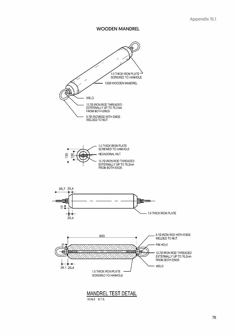
78
Appendix 15.1
WOODEN MANDREL

79
Appendix 16 – Pg 1
GENERAL REQUIREMENTS FOR TRANSMISSION SUBSTATION (66kV ONLY)
1. Where an application for supply of electricity necessitates the provision of a substation, the site shall be provided and substation constructed by the applicant consumer at his own cost.
2. In selecting a suitable site for the development of the 66KV substation, the following requirements shall be
used as a guide, in consultation with SP PowerGrid:
a) A minimum site area of 3500m² is required for the 66kV substation. b) Suitable and proper cable access shall be provided on at least two sides of the site for all cables entering
and leaving the proposed site. If there is any roadside drain fronting/surrounding the substation site, the developer is required to install cable ducts under-crossing the drain. If the depth of the drain is more than 2.0 metres from the proposed substation ground level, the cable ducts shall be installed to over-cross the drains with approval from relevant authorities. However, SPPG will not issue any letter of undertaking to divert cables laid to overcross any drains or other services.
c) There shall be no danger from flooding and fire hazards. d) The substation site shall be free from all encumbrances (existing and future proposed services). e) The substation structure may be an independent building or form part of a larger building. It shall be
located at the 1st storey level and must be readily accessible from the public road. Proper vehicular access to the substation shall be provided for transportation of substation equipment (estimated 150 tonnes) by normal means, i.e. truck and trailer. The gradient of the access road to the transmission substation site (66kV and above) shall not be steeper than 1:20.
f) The applicant consumer shall consider the effect of noise disturbance to neighbouring development in its
selection of the substation site. g) The applicant shall grant SPPG, its officers and agents an irrevocable licence at all times to have full and
unrestricted use of the substation and have free access thereto. h) The substation site within the substation perimeter fence shall be intended solely for the substation
development. 3. The substation building design shall incorporate all conditions/requirements as stated in the latest
Guidelines/Requirements for Transmission Substation Buildings. A softcopy of the Guidelines will be sent to the Developer upon confirmation of the substation project.
4. SPPG has been informed by EMA that all 66kV transmission substations will be classified as Critical Installations
(CI) subject to approval by MHA. As such, the Developer should make provisions for the engagement of a security consultant and for security features in proposed substation building design and implement security-by-design scheme once the substation is registered as a CI.
5. Approval from SPPG as well as all relevant government Agencies including EMA on substation security
requirements shall be obtained for the substation building design before tender for construction. 6. SPPA may utilize the substation and site in such manner as it deems fit. Subject to the applicant’s requirement
being fully provided for, SPPA shall be at liberty to use the substation for the purpose of supplying other customers or for the improvement of the transmission network (e.g. upgrading, modification to substation structure, alteration and addition works, etc.)
7. When a suitable site for the 66kV substation development has been finalised in consultation with SP PowerGrid, the applicant shall, in writing, officially inform SP PowerGrid of the site reserved for 66kV substation development. SP PowerGrid would then issue a letter of acceptance for the proposed site.

80
Appendix 16 – Pg 2
8. If, for any reason, the agreed site is found to be no longer feasible for a 66kV substation development, the applicant should note that the lead time required for the re-selection of a suitable site, design, construction and commissioning of the 66kV substation is at least 3 years. As a result, the applicant should consult SP PowerGrid on the power availability for the intended developments.
9. The applicant shall enter into a substation agreement with SP PowerAssets for the 66kV substation, to address matters such as operations and maintenance, security management and other obligations. This agreement shall be in effect before SP PowerGrid provides the final endorsement for the substation drawings.

81
Appendix 17.1
ENGINEERING REQUIREMENTS FOR CUSTOMER’S 22kV and 6.6 kV MAIN INCOMING SWITCHGEAR
O/C – Overcurrent relay type IDMTL with 3/10 characteristics.
Plug Setting =100%, Time Multiplier=0.1.
E/F – Earth fault relay type IDMTL with 3/10 characteristics.
Plug Setting =20%, Time Multiplier=0.1.
PW – PW main protection relay shall match with the SPPG’s end. The PW relays are typically Solkor R / RF, HOR4, MHOR unit protection relay (For 22kV connection)
A – Ammeter
CB – Circuit breaker
To circuit breaker trip circuit
Notes (Important): 1. Where there is more than one incoming service, a bus-section breaker shall be provided and be electrically and mechanically interlocked against parallel operation of the incoming services.
Notes (Protection): 1. Pilot wire protection CTs shall comply with the following requirements:
a. Rated knee point voltage at maximum secondary turns not less than 80V.
b. Exciting current at the rated knee point voltage not more than 150mA.
c. Resistance of the secondary winding, corrected to 75oC not more than 0.15 ohm.
2. No other auxiliary device shall be connected to the pilot wire protection CTs. Pilot wire protection CT star-point shall be towards protected line.

82
Appendix 17.2
ENGINEERING REQUIREMENTS FOR CUSTOMER’S LV MAIN INCOMING SWITCHGEAR
O/C – Overcurrent relay type IDMTL with 3/10 characteristics or DTL relay. For DTL relay, the setting shall be 100% of approved load with a time lag of not more than 0.5 sec. For IDMTL relay, the plug setting shall be 100% of approved load with a time multiplier of 0.1 (or 0.2 for approved load more than 1.5kA and up to 2.2kA and with source from SPPA’s 22kV substation).
E/F – Earth fault relay operating at primary fault current of 20% of approved load subject to a maximum of 120 Amp with time lag of not more than 0.5 sec.
CT – Current transformer Class 5P10, 15VA or better.
CB – Circuit breaker with adequate breaking capacity and circuit breaker using shunt trip shall be provided with series trip (Direct acting trip) device that operates with no time delay under short-circuit condition, or with HRC fuses in series.
To circuit breaker trip circuit.
Notes: Where there is more than one incoming service, a 4-pole bus-section breaker shall be provided and be mechanically interlocked against parallel operation of the incoming services.

83
Appendix 17.3
ENGINEERING REQUIREMENTS (TYPE 1) CUSTOMER 66kV FEEDER CONNECTION (see note i)
Numerical Relay System (OFC) (see note iv)
Feeder Main 1 Current Differential 1 (OFC)
Feeder Main 2 Current Differential 2 (OFC)
Inter-tripping 1 Current Differential 1 (OFC)
Inter-tripping 2 Current Differential 2 (OFC)
Interlocking (For CB control/safety)
Current Differential 1 (OFC) (see note v)
Remote End Interlock (on ES & DS)
Mechanical (see note v)
Notes: i) For designated customer and subjected to approval by SPPG for 66kV feeder connection exceeding 500m from SPPA substation. ii) Engineering and Protection details including interlocking and intertripping shall be discussed on application. iii) For reasons of obsolescence or availability, the type of relays and protection schemes shall subject to review and confirmation during the consultation period. iv) End to end intertrip and interlock schemes where applicable, shall be implemented via the current differential system. v) Interlock Scheme is for the operation, control / safety / signalisation of the isolator and/or circuit breakers at both ends. Details of the scheme requirement shall be discussed during consultation period. vi) Customer to supply and install OFC marshalling board of approved design to accommodate the optic fibre cables. vii) Customer shall be responsible for all power / auxiliary cable termination works at their equipment. viii) The designated Main 1 and Main 2 protection system shall be fully independent duplicated system. ix) Appropriate test facility such as test switches for trip isolation is to be provided for the unit protection system.

84
Appendix 17.4
ENGINEERING REQUIREMENTS (TYPE 2) CUSTOMER 66kV FEEDER – TRANSFORMER CONNECTION
(WITH 66kV ISOLATOR / CIRCUIT BREAKER) (see note i and viii)
Numerical Relay System (OFC/PW) (see note iv) Feeder Main 1 Current Differential 1 Feeder Main 2 Current Differential 2 Inter-tripping 1 Current Differential 1
Inter-tripping 2 Current Differential 2
Interlocking (For CB control / safety) Current Differential 1
(see note v)
Remote End Interlock (on ES & DS & neutral) Mechanical (see note v)
Notes: i) For designated customer and subjected to approval by SPPG for 66kV feeder-transformer connection <500m from SPPA substation. ii) Engineering and Protection details including interlocking and intertripping shall be discussed on application. iii) For reasons of obsolescence or availability, the type of relays, signalling equipment and protection schemes shall subject to review and confirmation during the consultation period. iv) Intertrip and interlock schemes where applicable, shall be implemented via the current differential system. v) Interlock scheme is for the operation, control / safety / signalisation of the isolator and/or circuit breakers at both ends. Details of the scheme requirement shall be discussed during consultation period. vi) Customer to supply and install OFC marshalling board of approved design to accommodate the optic fibre cables. vii) Customer shall be responsible for all power / auxiliary cable termination works at their equipment. viii) Customer intake may be a circuit breaker or an isolator depending on the length of the HV cable decided at the planning stage. ix) The designated Main 1 and Main 2 protection system shall be fully independent duplicated system. x) Appropriate test facility such as test switches for trip isolation is to be provided for the unit protection system.

85
Appendix 17.5
ENGINEERING REQUIREMENTS (TYPE 3) CUSTOMER 230kV FEEDER CONNECTION (see note i)
Notes: i) For designated customer and subjected to approval by SPPG for 230kV feeder connection. ii) Engineering and Protection details including interlocking and intertripping shall be discussed on application. iii) For reasons of obsolescence or availability, the type of relays, signalling equipment and protection schemes shall subject to review and confirmation during the consultation period. iv) Customer to supply and install OFC/Pilot marshalling board of approved design to accommodate the optic fibre cables and other auxiliary cables. v) Customer shall be responsible for all power / auxiliary cable termination works at their equipment. vi) Interlock scheme is for the operation, control / safety / signalisation of the isolator and/or circuit breakers at both ends. Details of the scheme requirement shall be discussed during consultation period. vii) Appropriate test facility such as test switches for trip isolation is to be provided for the unit protection system.
Supply from SPPA 230kV Source Station
Numerical Relay System (OFC) (see note iii) Feeder Main 1 Current Differential Feeder Main 2 Current Differential with
Distance Protection Teleprotection Signalling equipment
Inter-tripping Signalling equipment Remote End Interlock (on ES & DS & CB)
Mechanical & Electrical (via signalling equipment) (see note vi)
Switching sequencing Via signalling equipment (see note vi)

86
Appendix 17.6
ENGINEERING REQUIREMENTS (TYPE 4) CUSTOMER 230kV FEEDER – TRANSFORMER CONNECTION
(see note i)
Notes: i) For designated customer and subjected to approval by SPPG for 230kV feeder connection. ii) Engineering and Protection details including interlocking and intertripping shall be discussed on application. iii) For reasons of obsolescence or availability, the type of relays, signalling equipment and protection schemes shall subject to review and confirmation during the consultation period. iv) Customer to supply and install OFC/Pilot marshalling board of approved design to accommodate the optic fibre cables and other auxiliary cables. v) Customer shall be responsible for all power / auxiliary cable termination works at their equipment. vi) Interlock scheme is for the operation, control / safety / signalisation of the isolator and/or circuit breakers at both ends. Details of the scheme requirement shall be discussed during consultation period. vii) Appropriate test facility such as test switches for trip isolation is to be provided for the unit protection system.
Supply from SPPA 230kV Source Station
Numerical Relay System (OFC) (see note iii) Feeder Main 1 Current Differential Feeder Main 2 Current Differential with
Distance Protection Teleprotection Signalling equipment
Inter-tripping Signalling equipment Remote End Interlock (on ES & DS & CB)
Mechanical & Electrical (via signalling equipment) (see note vi)
Switching sequencing Via signalling equipment (see note vi)

87
Appendix 18
APPLICATION FOR DE-ENERGISATION / RE-ENERGISATION (ADRE)
Licensed Installation No Service No Voltage
Name of Installation:
Address of Installation:
Requested De-energisation Requested Re-energisation
Date: Time: *am/pm Date: Time: *am/pm
Contestable Customer: *Yes / No
#Name of Customer:
#MSS A/C No:
#Name of Retailer:
To: * Head of Section (EHV Network)
* Head of Section (Regional Network – * East / West) * Head of Section (Distribution Network – * West / Central / East / North / South) * Head of Section (Distribution Projects - * I / II / III) * Head of Section (Customer Project – * East / West)
1 I, the undersigned LEW for the above installation, wish to apply for a *de-energisation/re-energisation at the time stated above. My work, after the de-energisation, will involve the following:
*1 Routine Servicing 2 Others (Please specify):
2 * I / or ___________________________ (Name / Licence No of appointee approved by Regulation Division of
EMA) will attend to the *de-energisation / re-energisation PERSONALLY.
3 I understand that: -
(a) No work is to be carried out on the service cable until both SPPG officer and myself have signed the SDRE (“Statement for De-energisation and Re-energisation”) after we have safely isolated the service cable at both ends. (b) I am required to be on time on the approved date of de-energisation or re-energisation, failing which the SPPG officer may cancel any appointment made.
Signature:
Telephone /
HP No.:
Name:
Date:
Licence No:
* Grade:
Engineer / Technician / Electrician
Notes: (a) All requested date and time are subject to SPPG’s approval. (b) This form shall reach SPPG 7 business days before the requested date. (c) For urgent work on Sundays / Public Holidays and after office hours, LEW is required to co-ordinate with SPPG personally. (d) * Delete whichever not applicable. (e) # To be filled in for contestable customer
RNE Fax: 6253 6223 Tel: 6916 5226 Email: [email protected]
DNN Fax: 6765 3745 Tel: 6314 6172 Email: [email protected]
DP I Tel: 6916 8167 Email: [email protected]
RNW Fax: 6471 0854 Tel: 6916 5228 Email: [email protected]
DNS Fax: 6916 9886 Tel: 6916 5399 Email: [email protected]
DP II Fax: 6916 9888 Tel: 6916- 6423/6424 Email: [email protected]
CPE Fax: 6916 9872 Tel: 6916 7920 Email: [email protected]
DNE Fax: 6916 9874 Tel: 6916 7858 Email: [email protected]
DP III Tel: 6916 6968 Email: [email protected]
CPW Fax: 6916 9895 Tel: 6916 5020 Email: [email protected]
DNW Fax: 6916 9883 Tel: 6916 5015 Email: [email protected]
EHVN Fax: 6916 9887 Tel: 6916 5488 Email: [email protected]
DNC Fax: 6916 9892 Tel: 6916 5048 Email: [email protected]

88
Appendix 19
STATEMENT FOR DE-ENERGISATION AND RE-ENERGISATION (SDRE)
SP POWERGRID LTD
STATEMENT FOR DE-ENERGISATION AND RE-ENERGISATION (SDRE) Part 1 & II concern the de-energisation and re-energisation of the service cable specified below. Each statement is valid only when it is signed by both the LEW of the installation and the SP POWERGRID officer-in-charge of the de-energisation or re-energisation.
Name of Installation : _________________________________________________ MSS A/C No : ________________________________
Address of Installation: ________________________________________________________________(S)____________________________
Service Cable No:1 / 2 / 3 / 4 ** Meter ID(s): _________________________________________________________________________
Isolated From (Substation Name, OG Box, Etc) : _________________________________________________________________________
This de-energisation is *
Due to tripping
Requested by SP PowerGrid
Requested by LEW Routine Servicing Account closure** temporary / permanent (decommission and/or demolish) (For account closure, please omit Part II & III and send to SP Services Ltd) Others: ____________________________________________
* Please tick whichever is applicable ** Please delete whichever not applicable
PART I: DE-ENERGISATION STATEMENT (TO BE SIGNED AFTER DE-ENERGISATION) This statement is required only when work is to be done on the service cable by either the LEW or the SP PowerGrid officer, or both. If MSS A/C No starts with 930 and supply is switched off for more than 2 business days, please complete Part I and email to SP Services Ltd (Email: [email protected]) immediately upon turn-off. Customer’s intake switchgear SPPG’s outgoing switchgear
Date of turn off: ___________________ Date of turn off: ___________________
Time of turn off: ___________________ Time of turn off: ___________________
DECLARATION BY LEW: I, the undersigned LEW, hereby declare that the above service feeder has been turned off and safely isolated from the customer’s intake switchboard.
Signature : ___________________ Name : ____________________________ Licence No : _______________________
DECLARATION BY SP POWERGRID OFFICER: I, the undersigned SP POWERGRID officer, hereby declare that the above service cable has been de-energised and safely isolated from the SP PowerAssets’ network.
Signature : ___________________ Name : _____________________________Section : _______________________ As agent for and on behalf of SP PowerAssets Ltd
PART II: RE-ENERGISATION STATEMENT (TO BE SIGNED BEFORE RE-ENERGISATION)
Date : ___________________ Time : ___________________
DECLARATION BY LEW: I, the undersigned LEW, hereby declare that the customer’s switchgear, to which the abovementioned service feeder is connected, is cleared of all earthing leads, labour and tools, and that the switchgear is fit for re-energisation from SP POWERASSETS’ end with effect from the time specified above. I undertake to ensure that no work by any person will be carried out on the service feeder at the customer’s end until a new shutdown statement is signed by both parties.
Signature : ___________________ Name : ____________________________ Licence No : _____________________
ACKNOWLEDGEMENT BY SP POWERGRID OFFICER
Signature : ___________________ Name : _____________________________Section : _____________________ As agent for and on behalf of SP PowerAssets Ltd
PART III: DECLARATION BY LEW ON THE TIME OF TURN-ON OF INCOMING SUPPLY AT CUSTOMER’S INTAKE SWITCHBOARD (FOR CONTESTABLE CUSTOMERS ONLY)
To: SP Services Ltd, Remote Meter Reading Section (Email: [email protected])
DECLARATION BY LEW: I, the undersigned LEW, hereby declare that I had turned-on the incoming supply at customer’s intake switchboard at the following date/time:
Date of Turn-On: ___________________ Time of Turn-On : _________________________
Signature: ___________________ Name: _________________________ Licence No : _____________________

89
Appendix 20 – Pg 1
CERTIFICATE OF READINESS FOR THE ENERGIZATION OF SERVICE CONNECTION (COR)
Name of Customer Installation:
Address:
Customer Installation Licence No/Expiry Date:
Connection Voltage:
Approved Load:
Name of Connection Cable(s):
Owned by Connection Applicant (Yes / No)
MSS Account No:
Name of Retailer:
Certification By LEW I, ______________________(name) the undersigned LEW, hereby certify that the service connection*, the equipment and works at the above installation (Licence No: ______________) are now ready and fit for energisation with effect from the date and time specified below. Date: Time:
I certify that: a. Protection details are as follows:
CT Ratio: /1A or 5A*
Short-Time Withstand Current Ratings of Main Supply Incoming Switchgear __________ KA for 1 sec or 3 sec
Main 1 Type:
Main 2 Type*: Direct Acting Tripping Setting:
O/C Type: Setting:
E/F Type: Setting:
b. The switching equipment/transformer/service connection* and all associated apparatus related to the service connection have been tested and checked by me and they have passed the pre-commissioning checks and tests in compliance with the Market Rules, Transmission Code, Handbook on How to Apply for Electricity Connection, Connection Agreement, all other applicable standards, and the associated protection systems have all been proven effective.
c. The main protection schemes for the connection have been commissioned by load simulation method on date: ______________** d. For multi-metered installation with the exception of HDB residential installation, the metering scheme has been designed as master/sub-metering scheme.
e. All necessary meters have been installed. * Delete where not applicable
** To indicate NA where protection scheme is not applicable

90
Appendix 20 – Pg 2
f. The safety coordination requirements of the Transmission code have been fully complied with. g. All workmen have been withdrawn and warned that it is no longer safe to continue to work on
the equipment without a ‘Permit-to-work (PTW)’, and that all tools, scaffolding, ladders, construction materials including any temporary local earthing connections have been removed from the equipment, and all protective screens or guards, if any, have been securely fixed and the appropriate warning signs displayed and that all keys, if any, necessary for the isolation and operation of the equipment have been handed to me.
h. All circuit earth on equipment to be energised are removed.
i. Equipment to be energized in this request (the diagram must clearly indicate the portion of the
equipment to be energized. If the space is insufficient, please provide diagram as attachment) is shown below:
Name & Signature of LEW requesting for energization of supply line
Licence No. Date

91
Appendix 21

92
Appendix 22

93
Appendix 23 APPLICATION FOR APPOINTMENT FOR
ENERGISATION OF SERVICE CONNECTION BY FAX
FACSIMILE TRANSMITTAL SHEET Total No. of Pages (including this page): [ ]
To: Director, Electrical Installation From [Name of LEW]:
Company: SP Services Ltd Company:
Email Address: [email protected] Email Address:
Date: Office Telephone No.:
Application No.: Tel No. / Handphone No.:
MSS A/C No.: Approved Load:
I would like to make an appointment for energisation of service connection to _______________________________________________________________________________________________ ____________________________________________________________________________________ (site address) The following documents are faxed together with this application.
Documents Tick if applicable
1) Opening of Account with SP Services Ltd
2) Opening of Account with Electricity Retailer (for contestable consumer)
3) Confirmation of meters already fixed (for HT and contestable consumer)
4) Electrical Installation Licence issued by EMA
5) Certificate of Compliance (original to be submitted to SPPG’s project officer)
6) Letter from IRAS confirming official address (For new connection / address)
7) Meter Declaration Report ( For installation with existing meter)
8) Application for De-Energisation/Re-Energisation(ADRE) for existing supply
9) HDB Residential Block Common Services meter : ( KVA)
10) Commissioning of IGS system (with Application for Net Export Rebate form etc)
11) Wholesaler (Generation) Licence ( Required for Generation Capacity 1 MWac or more, but less than 10MWac)
12) Others (Please specify)
I will submit the Certificate of Readiness on site, failing which service connection shall not be energised and SPPG & SPPA shall not be liable for any loss arising therefrom. I understand that the date of appointment is subject to confirmation by SP Services Ltd and the appointment date shall not be earlier than 4 business days from this fax date. **If turn-on appointment is less than 4 business days, payment for express meter installation is required by Electrical Meters Section (SP PowerGrid Ltd), subject to availability of resources. The preferred appointment dates (at least 4 business days) are as follows: 1st choice: Date: Time: Morning / Afternoon* 2nd choice: Date: Time: Morning / Afternoon* 3rd choice: Date: Time: Morning / Afternoon*
**Express Appointment Date: __________________ Time: Morning / Afternoon* (less than 4 business days) (Express Meter Installation Fee Imposed by SPPG)
$150 (weekday) or $300 (weekend/public holiday) per manday per site. Payment by cheque only and shall be made at SP PowerGrid, Electrical Meters Section Name & Signature of LEW Licence No. ……………………………………………………………………………………………………………………………………
FOR OFFICIAL USE
Your application for the above is rejected. Please refer to the attached appendix for your necessary follow-up action.

94
Appendix 24
TECHNICAL REQUIREMENTS FOR SERVICE CABLE AND METER COMPARTMENT FOR LANDED HOUSES
1 The service cable termination and meter compartment shall be located at the front-gate pillar/perimeter wall such that it is accessible to SPSL's and SPPG's officer without the need to enter the customer's premises.
2 It shall be constructed of concrete, brick or high impact fibre glass and shall be completely weatherproof.
Provision shall be made to prevent any stagnation of water within the compartment. 3 The main dimensions of the compartment are shown in the layout drawing (see Appendix 24.1). The depth
of the compartment measured from the meter board surface to the compartment door shall be between 200 mm and 300 mm.
4 A meter board of 20 mm thick and constructed of teak wood or any hardwood chemically treated against termite attack shall be provided. Plywood board is not acceptable. A minimum space of 450 mm (W) x 800 mm (H) shall be allowed for the termination of the service cable and the installation of service MCBs and meters. Customer's MCBs or connectors shall be mounted on a separate board in a separate compartment.
5 A hinged door with a clear glass viewing window shall be provided. The viewing window with a 200 mm
(W) x 300 mm (H) x 6 mm (thickness) clear cover shall be positioned to be directly in front of the meter location. To avoid high humidity and condensation within the compartment, sufficient ventilation shall be provided. The access door shall not have less than 450 mm clear access opening.
6 The door shall be constructed of stainless steel, anodised aluminium or high impact type fibre glass
reinforced material. Where a metal door is provided, a means of earthing shall be provided. 7 One 100mm diameter UPVC lead-in pipe shall be provided for SPPA service cable. The pipe shall be laid
up to 100 mm from the floor slab of the electric meter compartment and shall undercross any drain in front of the compartment.
8 There shall be adequate standing space in front of the compartment to facilitate meter reading, installation
and maintenance work. Where there exists a drain in front of the compartment, a suitable concrete platform or hinged galvanised steel grating shall be provided.
9 The compartment shall be exclusively used for service cable and electricity meter. No water meter, gas
meter or other facilities shall be placed within the same compartment. 10 Please obtain clearance from URA's Development Control Division if the meter-box structure exceeds their
stipulated dimensions.
URA address: 45 Maxwell Road
The URA Centre Singapore 069118

95
Appendix 24.1
STANDARD METER COMPARTMENTS AT GATE PILLAR
IF THE METER COMPARTMENT IS LOCKED, THE LOCK MUST COMPLY WITH THE REQUIREMENETS IN SECTION 6.1.6. ALL DIMENSIONS ARE IN mm. SCALE: NOT TO SCALE

96
Appendix 25
STANDARD METER BOARD
Note: Drawing not to scale. All dimensions in mm.

97
Appendix 26
STANDARD SIZE FOR SINGLE-PHASE METER BOARD
1 Minimum space for single-phase meter position (enclosed within broken lines):- (i) 230mm (W) x 280mm (H) for 35 sq. mm cable and below (ii) Depth from surface of meter board to the surface of the meter enclosure door must be at least 200mm
or greater. 2 A customer’s earthing terminal shall be provided on the meter board for termination of the earthing lead
and earth continuity conductor 3 Not more than one wire should be connected to each terminal of the meter terminal block 4 All wires on the meter board from MCB / Cut-out to the meter and meter to main switch should be
preferably be run on the surface 5 The size of cables to be used for connection to meters should not exceed 35 sq. mm 6 The length of wire “L” protruding from the meter board to the meter terminal shall be at least 200mm 7 For meters grouped in a centralised meter room etc, an additional minimum spacing of 70mm is necessary
between each row of meters for ease of installation / change 8 The meter cables should follow the new cable colour code stated in SS CP5. 9 Some typical layouts are shown in figures A, B and C Note: drawings not to scale. All dimensions in mm.

98
Appendix 27
STANDARD SIZE FOR THREE-PHASE METER BOARD
1 Minimum space for three-phase meter position (enclosed within broken lines) (i) 400mm (W) x 400mm (H)
(ii) Depth from surface of meter board to the surface of the meter enclosure door must be at least 200mm or greater.
2 A customer’s earthing terminal shall be provided on the meter board for termination of the earthing lead and earth continuity conductor
3 Not more than one wire should be connected to each terminal of the meter terminal block 4 All wires on the meter board from MCB / Cut-out to the meter and meter to main switch should be
preferably be run on the surface 5 The size of cables to be used for connection to meters should not exceed 35 sq. mm 6 The length of wire “L” protruding from the meter board to the meter terminal shall be at least 200mm 7 The meter cables should be colour-coded respective to their phases or shrouded with coloured sleeving Note: drawings not to scale. All dimensions in mm.

99
Appendix 28
CT METER PANEL FOR LOW VOLTAGE SUPPLY
Note: Drawing not to scale. All dimensions in mm.

100
Appendix 29
METHODS FOR SEALING METERING PANELS
All holes for threading seal wires should be 2mm size
Drawing not to scale. All dimensions in mm.

101
Appendix 30
ENCLOSURE FOR LOW VOLTAGE METERING CURRENT TRANSFORMERS
METERING CTS BOX Note: All screws, bolts and nuts to be of brass. The Metering CT Box 1.6mm thick mild steel frame to be properly and strongly welded on the Switchboard Main Structural Framework. The Metering CT Enclosure shall be located immediately after the incoming Circuit Breaker(s). Drawing not to scale. All dimensions in mm.

102
Appendix 31
HV METERING KIOSK REQUIREMENTS (FOR 1 OR 2 FEEDERS)
Note: Drawing not to scale. All dimensions in mm
Side Elevation of Metering Kiosk for 1 or 2 feeder panel The following are required: a) Metering kiosk: 650mm by 1700mm by minimum height 2400mm of solid brick as shown. b) Floor opening 50mm by 50mm as shown. c) Staircase and 1000mm landing where required. d) Steel or heavy duty aluminium door of 1200mm wide by 2100mm height to be fitted with one of the SPPA approved master series locksets as given in section 6.1.6. e) One 2 gang 13A switched socket outlet and two 40W lighting points. f) If landing is above ground level, safety railings must be provided. g) No louvers to be provided for metering kiosk.

103
Appendix 32 – Pg 1
HV METERING KIOSK REQUIREMENTS (FOR 3 OR 4 FEEDERS)
Note: Drawing not to scale. All dimensions in mm
Side Elevation of Metering Kiosk for 3 or 4 feeder panel
The following are required: a) Metering kiosk: 810mm by 2650mm by minimum height 2400mm of solid brick as shown. b) Floor opening 100mm by 60mm as shown. c) Staircase and 1000mm landing where required. d) Steel or heavy duty aluminium door of 800mm wide by 2100mm height to be fitted with one of the SPPA approved master series locksets as given in section 6.1.6. e) One 2 gang 13A switched socket outlet and two 40W lighting points. f) If landing is above ground level, safety railings must be provided.
g) No louvers to be provided for metering kiosk.

104
Appendix 32 – Pg 2
HV METERING KIOSK REQUIREMENTS (FOR 3 OR 4 FEEDERS)
a = 40W fluorescent lamps b = 2 gang 13A switched socket outlet c = 10A switch for fluorescent lamps
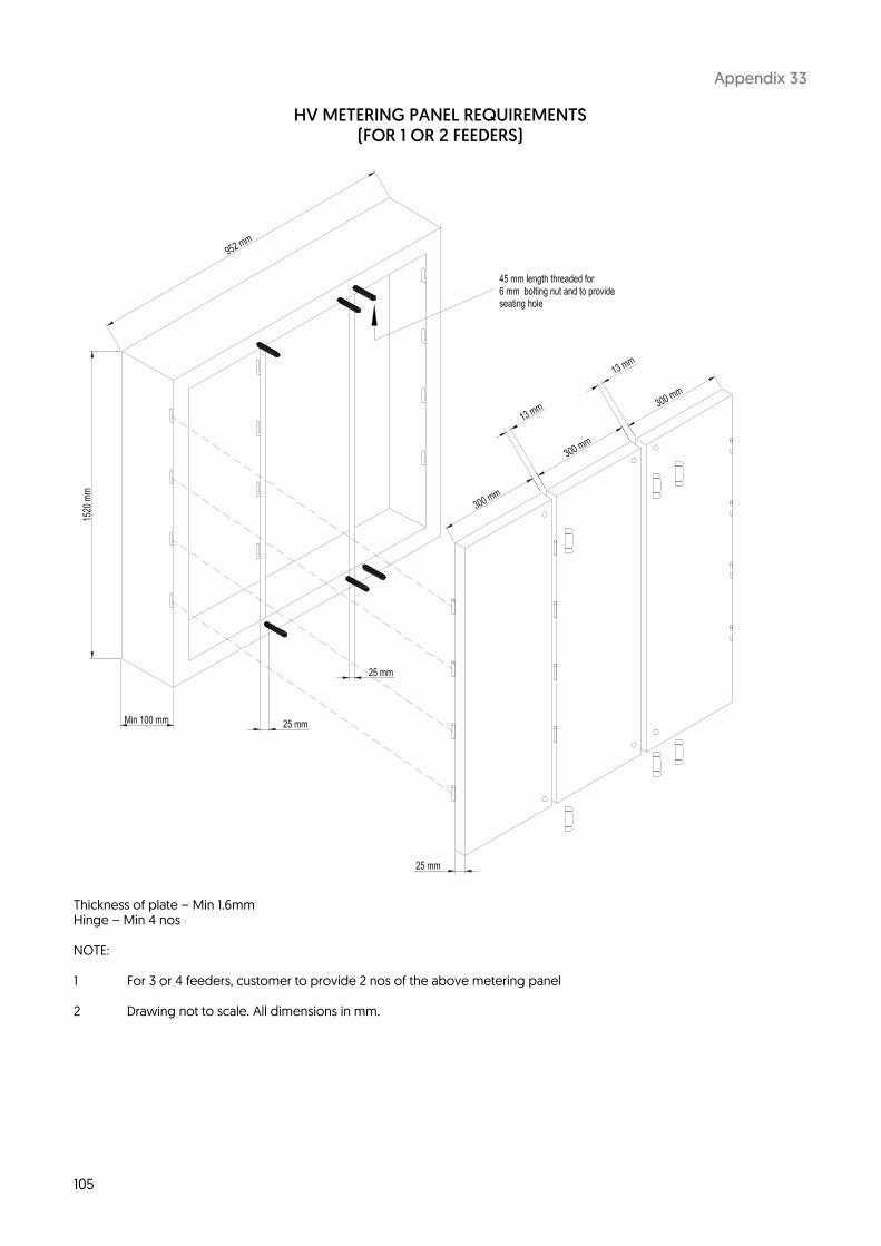
105
Appendix 33
HV METERING PANEL REQUIREMENTS (FOR 1 OR 2 FEEDERS)
Thickness of plate – Min 1.6mm Hinge – Min 4 nos NOTE: 1 For 3 or 4 feeders, customer to provide 2 nos of the above metering panel 2 Drawing not to scale. All dimensions in mm.

106
Appendix 34
METERING VTs VOLTAGE RATIO, SEQUENCE & PHASE ANGLE TESTS REPORT
Customer: A/C No.: Project Address:
PT No.: Voltage Ratio : For Feeder No.:
I, , EMA Licensed No. had carried out the above test and results are given below.
I hereby certified that the VTs are correctly connected up for tariff metering. Stamp & Signature of LEW Date:

107
Appendix 35
BASIS FOR THE SERVICE CONNECTION CHARGE
1 Service Connection Charges for Low Tension (LT) Connection All LT consumers are required to pay a one-time upfront service connection charge. These charges which vary for different load requirements are categorised depending on the provision of a substation. For consumers with substations, their supply intake point is usually adjacent to the substation, which requires a service cable of approximately 15m in most instances. Therefore, the standard connection charge is computed based on a cost of service cable length of 15m. Consumers shall pay the additional cost for service cable exceeding 15m. In addition, consumers shall also pay for those dedicated assets, such as switchgear and transformers, which are serving them and do not benefit others. For individual consumers without substations, the cost of LT service cable for the same capacity may vary widely depending on their locations with respect to the nearest LT mains. These consumers are not the sole beneficiaries of the extension of the LT network. To achieve a greater degree of equity in terms of cost for these general consumers, a standard cost approach is adopted by grouping consumers with similar supply requirements. The average global cost per kVA is determined based on past statistics. For example, this category of consumers which comprises mainly landed residential owners, applying for the same applied load will pay the same standard connection charge regardless of the location of their premises from the existing LT network. Standard charges are only applicable to consumers who are connected to the shared network. The rates, which are approved by EMA, are available in the Transmission Services Rate Schedule. Standard charges are not applicable to consumers where the network created is unlikely to be shared by others. Some of these include supply to HDB premises, premises involving installation of bigger capacity cable in order to overcome the excessive voltage drop, temporary work sites, public installations and offshore island premises. These consumers would have to pay for the full connection network cost, based on user-pay principle, as they are the main beneficiaries. 2 Service Connection Charges for HT, EHT and UHT Connection Consumers receiving HT, EHT and UHT connection shall pay the cost of the service connections to their intake equipment including cables, associated equipment and facilities to effect the connection of consumer’s equipment to SPPA’s substation/network. The service connection shall cater for single contingency. Consumers requesting additional level of contingency above single contingency are required to pay for the full cost of such provision. 3 Dedicated Distribution Substation The developer or consumer shall pay the full cost of all associated equipment and facilities under a dedicated network/substation scheme for which the network capacity is intended to serve the developer’s development or consumer’s premise(s) exclusively. A substation comprises land, building, electrical equipment and associated cables. A substation which serves a development or premise has to be provided and paid for by the developer or consumer. As the capacity of electrical equipment is lumpy, the substation may have excess capacity. The developer or consumer will carry the cost of this excess capacity which cannot be avoided. As this substation is required to serve mainly the development’s or consumer’s load, it is considered a dedicated substation. To reduce cost, a developer or consumer can choose to let SPPA bear the cost of the electrical equipment and associated cables, thus making the network/substation a non-dedicated one. In return, SPPA must be allowed to allocate the excess capacity to other consumers. Even after the excess capacity is allocated, SPPA shall return the capacity to the developer or consumer if his demand grows later provided existing allocated capacity to other consumers can be diverted. The latter provision shall also apply to the decommissioning of the substation. At present, most substations provided by developers or consumers are non-dedicated substations.

108
Appendix 36
STANDARD SERVICE CONNECTION CABLES The type of service connection cables for terminating into a customer’s intake point for the applied load connected at the LV and 22kV level and the typical connection schemes are illustrated as follows:
Voltage Level Applied Load(kVA) Size of Cables Type of cables
LV
Up to 15 35mm2 2Core Cu/XLPE/SWA/PVC
16 – 23 35mm2 2Core Cu/XLPE/SWA/PVC
16 – 45 35mm2 4Core Cu/XLPE/SWA/PVC
46 – 75 35mm2 4Core Cu/XLPE/SWA/PVC
76 – 140 120mm2 4Core Al/XLPE/SWA/PVC
141 – 180 185mm2 4Core Al/XLPE/SWA/PVC
181 – 230 300mm2 4Core Al/XLPE/SWA/PVC
231 – 280 300mm2 4Core Cu/XLPE/SWA/PVC
281 – 460 2x300mm2 4Core Al/XLPE/SWA/PVC
461 – 560 2x300mm2 4Core Cu/XLPE/SWA/PVC
561 – 1000 7x500mm2 1Core Cu/XLPE/PVC
1001 – 1500* 7x1000mm2 1Core Cu/XLPE/PVC
1001 – 2000^ 2 sets of 7x500mm2 1Core Cu/XLPE/PVC
2001 – 3000^ 3 sets of 7x500mm2 1Core Cu/XLPE/PVC
22kV+
Up to 12750kW^ 2 X 300mm2 3Core Cu/XLPE/DSTA/PVC
12751 – 25500kW^ 4 X 300mm2 3Core Cu/XLPE/DSTA/PVC
Pilot cables 1.5 mm2 5 pair Cu/PE/DSTA/PVC
For development whereby the service connection cables is to be supplied and installed by the customer (i.e. via cable tray or the customer’s switchroom is not at the same level as SPPA’s switchroom), the LEW shall, in the event of a non-standard cable installation, seek approval from SPPG prior to installation.
* applies to upgrading of applied load
+ The 22kV scheme is designed to cater for the outage of a single service connection circuit. The customer is required to reduce or maintain his load to within the rated capacity of the remaining service connection circuit(s) in the event of a busbar failure or outage for maintenance. The 22kV cable should be able to withstand single-phase to earth fault current of up to 4kA.
^ Each set of service connection cables shall not be operated in parallel at all times. There must be an electrical and mechanical interlocking bus coupler between each set of cables terminating into the customer’s switchboard as shown below to prevent any possible parallel operation:

109
Appendix 37
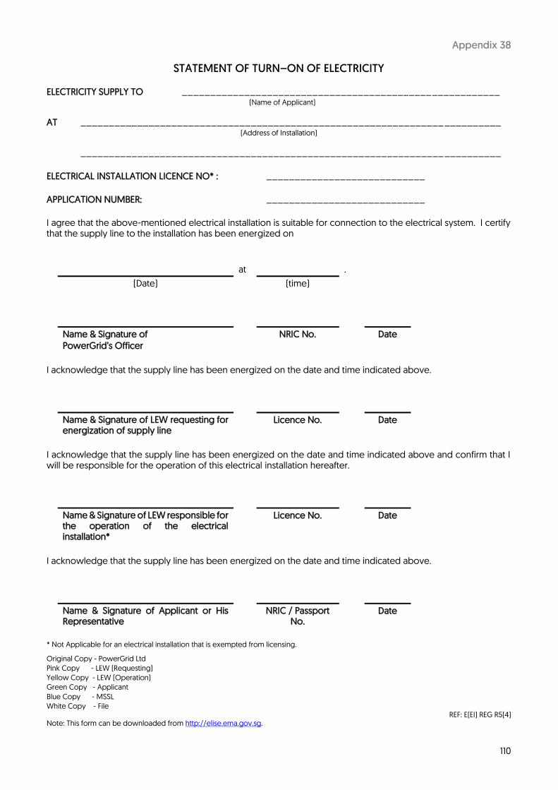
110
Appendix 38
STATEMENT OF TURN–ON OF ELECTRICITY
ELECTRICITY SUPPLY TO ________________________________________________________ (Name of Applicant)
AT __________________________________________________________________________ (Address of Installation)
__________________________________________________________________________ ELECTRICAL INSTALLATION LICENCE NO* : ____________________________
APPLICATION NUMBER: ____________________________ I agree that the above-mentioned electrical installation is suitable for connection to the electrical system. I certify that the supply line to the installation has been energized on
at .
(Date) (time)
Name & Signature of PowerGrid’s Officer
NRIC No. Date
I acknowledge that the supply line has been energized on the date and time indicated above.
Name & Signature of LEW requesting for energization of supply line
Licence No. Date
I acknowledge that the supply line has been energized on the date and time indicated above and confirm that I will be responsible for the operation of this electrical installation hereafter.
Name & Signature of LEW responsible for the operation of the electrical installation*
Licence No. Date
I acknowledge that the supply line has been energized on the date and time indicated above.
Name & Signature of Applicant or His Representative
NRIC / Passport No.
Date
* Not Applicable for an electrical installation that is exempted from licensing.
Original Copy - PowerGrid Ltd
Pink Copy - LEW (Requesting)
Yellow Copy - LEW (Operation)
Green Copy - Applicant
Blue Copy - MSSL
White Copy - File REF: E(EI) REG R5(4)
Note: This form can be downloaded from http://elise.ema.gov.sg.

111
Appendix 39 – Pg 1
REQUIREMENTS FOR EMBEDDED GENERATION FACILITY / INTERMITTENT GENERATION SOURCES (IGS)
The consumer applying to connect an embedded generation facility / IGS is required to obtain SPPA’s approval and shall comply with the technical, safety & operational and commercial & legal requirements below: High Tension and above (6.6kV & above) consumers with embedded generation / IGS, will need to choose one of the 3 backup schemes (full or partial) required: (1) Summation Scheme; (2) Capped Capacity Scheme; or (3) Extended Capped Capacity Scheme. The consumer will need to sign a Supplemental Agreement with the Transmission Licensee to reflect their choice of backup scheme for the service connection.
Consumers adopting Summation Scheme and not on Solar Generation Profiling option shall provide metering transformer(s), both voltage and current for HT and above connections, and current only for LT connections, and a suitable facility (including all necessary pre-wiring) to house the summation meter(s), which will be provided and installed by SPPA, for measuring output of all the generators / IGS, which is summed with import from grid in the same time intervals to determine the Maximum Demand. If the embedded generation / IGS in the premises is 1MWac or above, generation meters need to be installed, which the consumer can request to double up as summation meters (SPPA will need to remove any existing summation meters). Capped Capacity and Extended Capped Capacity Scheme requirements are in Appendix 39.1 and 39.2 respectively. For more information on PV requirements, please refer to the SP Group website at www.spgroup.com.sg.
1 Technical Requirements a) Real and reactive power/voltage output and voltage and frequency response times must be within agreed limits
b) To comply with the voltage imbalance, voltage fluctuation and harmonic content requirements as specified in the Transmission Code c) Ensure that there is no interference to SPPA’s equipment or any other directly or indirectly connected consumers d) Ensure adequate partitioning of the embedded generation facility equipment from SPPA’s equipment
e) Where required by SPPA, to install harmonic device to ensure compliance with the harmonics standard at PCC as specified in the Transmission Code f) LEW is required to submit fault level reports to SPPG’s Distribution Planning Section. The embedded generation system shall limit their fault level contribution to the grid to a level acceptable to SPPG.
2 Safety & Operational Requirements a) Provide an interlocking and inter-tripping facility for the service connection that meets SPPA’s requirement
b) Fit embedded generation facility with reverse power relays to prevent export of power to the transmission system. However, this requirement will not apply in the event that EMA / EMC had given approval for the export of power to the transmission system c) Not operate the embedded generation facility in islanding mode, i.e. the embedded generator must isolate itself from the distribution network when there is a fault/tripping on the latter or the consumer’s installation (non-islanding protection)
d) Provide a synchronizing facility at the incoming switchboard of its service connection and ensure that any output is always synchronized with the distribution network
112
Appendix 39 – Pg 2
3 Commercial & Legal Requirements The consumer with an embedded generation facility / IGS shall:
a) Pay use of system charges in accordance with the Transmission Services Rate Schedule
b) Indemnify SPPA
i) for all losses and liabilities arising from any loss of synchronisation caused by any tripping or re-closing of any breakers in the transmission system and the embedded generation facility / IGS connected in parallel to the transmission system ; and
ii) Against losses to third parties caused by impedance, disruption degradation interference or failure of transmission services to third parties caused by the system or works carried out on the transmission system.
c) Certify to SPPG that the embedded generation facility meets all conditions of the relevant
legislation, regulation (including installation, fire and safety, noise and environment)
d) Conduct regular site tests and notify SPPG of the results
e) Allow SPPG to conduct inspection of, disconnect and enforce conditions in respect of the service connection if the embedded generation facility / IGS fails to meet any of the above requirements f) Resolve, at its own expense, all third party complaints concerning the embedded generation facility / IGS (e.g. complaints due to noise, or aesthetic reasons); and
g) Subject to SPPG approval, use the service connection at its own risk to operate in parallel with its embedded generation facility / IGS.

113
Appendix 39.1 – Pg 1
TERMS AND CONDITIONS FOR CAPPED CAPACITY SCHEME (CCS)
1 The Consumer shall at its own expense, install and maintain, in accordance with such requirements that the Transmission Licensee may from time to time stipulate:
1.1 at the Consumer’s incoming switchboard (or at such other point that Transmission Licensee may
specify), a Load Limiting Device (“LLD”), which will automatically disconnect the Service Connection from the Transmission System in the event (“Event”) that the Consumer’s intake from the Transmission System exceeds one hundred and twenty percent (120%) of the Contracted Capacity (“CC”) for more than ten (10) seconds continuously.
1.2 at the HT metering kiosk (or at such other point that Transmission Licensee may specify), a Load
Monitoring Device (“LMD”) including device licence, all control cables for the LMD as well as metering accessories for the Transmission Licensee to monitor the Consumer’s intake from the Transmission System.
2 Upon installation, all title, rights and interest in the LMD shall vest immediately in the Transmission Licensee. However, the Consumer shall ensure that:
2.1 The LMD shall at all times be set and adjusted to the satisfaction of the Transmission Licensee;
2.2 No modification, reset or adjustment to the LMD is carried out without first obtaining the
Transmission Licensee’s approval;
2.3 The initial testing, commissioning and subsequent annual testing of the LMD as well as any
modification, reset or adjustment to the LMD approved by the Transmission Licensee is to be carried out by a Licensed Electrical Worker and in the presence of a representative from the Transmission Licensee;
2.4 The LMD is re-tested and re-commissioned as and when required at the discretion and direction of the Transmission Licensee;
2.5 All test results are submitted to the Transmission Licensee at such address as notified by the Transmission Licensee within two (2) weeks from the date of the testing;
2.6 The representatives of the Transmission Licensee are granted unrestricted access to substation
premises for on-site inspection and retrieval of data from the LMD;
2.7 The LMD is covered under a valid maintenance contract providing for relevant technical support and replacement parts to keep the LMD in good operational condition at all times; and
2.8 If any defect in the LMD is detected, the Consumer is required to rectify these defects, and replace the LMD if necessary within two (2) weeks from the date of detecting these defects.

114
Appendix 39.1 – Pg 2
3 The Transmission Licensee shall be entitled to witness all testings of the LMD (as set out in clause 2 above) at its own expense. All other expenses in connection with the testing of the LMD shall be borne by the Consumer.
4 The conversion to CCS shall be effective upon the following (the “CCS Effective Date”):
4.1 the Consumer’s compliance with Item 1 above; and
4.2 the successful commissioning of the LLD and LMD.
5 In the event that the LLD fails to cap the power demand (kW) drawn from the network in the circumstances as described in Item 1.1, the Uncontracted Standby Capacity Charge (“USCC”) shall apply and be payable.
6 The USCC is a monthly charge payable in any month for the Uncontracted Standby Capacity utilised. The
Uncontracted Standby Capacity is the peak power demand in kW drawn from the network exceeding 120% of CC, recorded from the time the power drawn exceeds 120% of CC to the time the power drawn falls below 120% of CC. This peak power demand is recorded by the LMD at single second intervals.
7 The rate of USCC shall be the prevailing rate stated in the Transmission Service Rate Schedule. SPPA
reserves the right to review the USCC rate applicable to the Consumer from time to time, such review to be subject to EMA’s approval. The current rate for USCC is 5 times of the CC Charge for demand drawn exceeding 120% of CC.
8 For each Event, as defined in Item 1.1 above, the Consumer is required to submit, within two weeks of the
occurrence of the Event, a report to the Transmission Licensee detailing each Event. The details shall include but not be limited to: (a) Time (accurate to seconds) and date of the Event(s), supported by system event log listings; (b) Detailed description of the Event, in particular the cause(s) of Event; and
(c) Remedial actions to prevent future Events.
9 The Consumer shall ensure that multiple sources of Transmission System are not connected in parallel at any time, and that any switching between circuits is undertaken on “black changeover” or “break before make” basis.
10 The Transmission Licensee reserves the right to withdraw the CCS from the Consumer if the Consumer fails
to comply with the terms and conditions applicable to the scheme, and to offer only the Summation Scheme (as outlined in Clause 12.14(a) of the CCA) to such Consumer.
11 The Consumer acknowledges and accepts that in the event of a change in scheme for whatever reason,
the Service Connection may be disconnected temporarily to facilitate the installation of energy meters and other equipment for the purposes of the implementation of the Summation Scheme.

115
Appendix 39.2 – Pg 1
TERMS AND CONDITIONS FOR EXTENDED CAPPED CAPACITY SCHEME (ECCS)
1 The Consumer shall at its own expense, install and maintain, in accordance with such requirements that the Transmission Licensee may from time to time stipulate:
1.1 at the Consumer’s incoming switchboard (or at such other point that the Transmission Licensee
may specify), a Load Limiting Device (“LLD”), which will automatically disconnect the Service Connection from the Transmission System on the happening of any one of the following events (“Event”):
(a) when the Consumer’s intake from the Transmission System exceeds one hundred and
twenty percent (120%) of the Contracted Capacity (“CC”) for more than one hundred (100) seconds continuously; or
(b) when the Consumer’s intake exceeds two hundred percent (200%) of the CC for more than ten (10) seconds continuously.
1.2 at the HT metering kiosk (or at such other point that Transmission Licensee may specify), a Load Monitoring Device (“LMD”) including device licence, all control cables for the LMD as well as metering accessories for the Transmission Licensee to monitor the Consumer’s intake from the Transmission System.
2 Upon installation, all title, rights and interest in the LMD shall vest immediately in the Transmission Licensee. However, the Consumer shall ensure that:
2.1 The LMD shall at all times be set and adjusted to the satisfaction of the Transmission Licensee;
2.2 No modification, reset or adjustment to the LMD is carried out without first obtaining the Transmission Licensee’s approval;
2.3 The initial testing, commissioning and subsequent annual testing of the LMD as well as any modification, reset or adjustment to the LMD approved by the Transmission Licensee is to be carried out by a Licensed Electrical Worker and in the presence of a representative from the Transmission Licensee;
2.4 The LMD is re-tested and re-commissioned as and when required at the discretion and direction
of the Transmission Licensee;
2.5 All test results are submitted to the Transmission Licensee at such address as notified by the Transmission Licensee within two (2) weeks from the date of the testing;
2.6 The representatives of the Transmission Licensee are granted unrestricted access to substation premises for on-site inspection and retrieval of data from the LMD;
2.7 The LMD is covered under a valid maintenance contract providing for relevant technical support and replacement parts to keep the LMD in good operational condition at all times; and

116
Appendix 39.2 – Pg 2
2.9 If any defect in the LMD is detected, the Consumer is required to rectify these defects, and replace the LMD if necessary within two (2) weeks from the date of detecting these defects.
3 The Transmission Licensee shall be entitled to witness all testing of the LMD (as set out in clause 2 above)
at its own expense. All other expenses in connection with the testing of the LMD shall be borne by the Consumer.
4 The conversion to ECCS shall be effective upon the following (the “ECCS Effective Date”):
4.1 the Consumer’s compliance with Item 1 above; and 4.2 the successful commissioning of the LLD and LMD.
5 In the event that the LLD fails to cap the power demand (kW) drawn from the network in the circumstances as described in Item 1.1, the Uncontracted Standby Capacity Charge (“USCC”) shall apply and be payable. The USCC is a monthly charge payable in any month for the Uncontracted Standby Capacity utilised.
6 For the purposes of this ECCS, the term “Uncontracted Standby Capacity” shall mean the capacity by which the demand in kW drawn from the network:
6.1 exceeds 120% up to a level of 200% of the CC at the metered intake supply point for a duration of
more than 100 seconds continuously; or 6.2 exceeds 200% of the CC at the metered intake supply point for a duration of more than 10 seconds
continuously.
7 The rate of USCC shall be the prevailing rate stated in the Transmission Service Rate Schedule. SPPA reserves the right to review the USCC rate applicable to the Consumer from time to time, such review to be subject to EMA’s approval. The current rate for USCC is:
7.1 5 times of the CC Charge for demand drawn exceeding 120% up to 200% of CC; and 7.2 12 times of the CC Charge for demand drawn exceeding 200% of CC.
8 For each Event, as defined in Item 1.1 above, the Consumer is required to submit, within two weeks of the occurrence of the Event, a report to the Transmission Licensee detailing each Event. The details shall include but not be limited to: (a) Time (accurate to seconds) and date of the Event(s), supported by system event log listing; (b) Detailed description of the Event, in particular the cause(s) of Event; and (c) Remedial actions to prevent future Events.
9 The Consumer shall ensure that multiple sources of Transmission System are not connected in parallel at
any time, and that any switching between circuits is undertaken on “black changeover” or “break before make” basis.
10 The Transmission Licensee reserves the right to withdraw the ECCS from the Consumer if the Consumer
fails to comply with the terms and conditions applicable to the scheme, and to offer only the Summation Scheme (as outlined in Clause 12.14(a) of the CCA) to such Consumer.
11 The Consumer acknowledges and accepts that in the event of a change in scheme for whatever reason,
the Service Connection may be disconnected temporarily to facilitate the installation of energy meters and other equipment for the purposes of the implementation of the Summation Scheme.
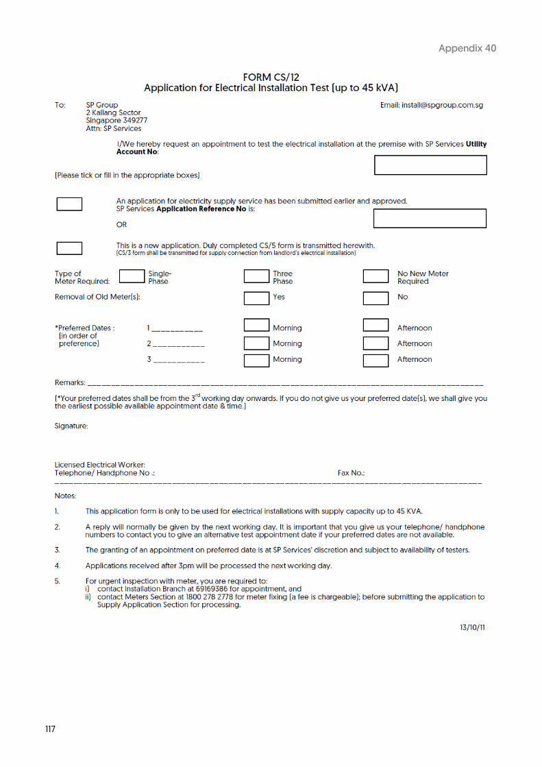
117
Appendix 40

118
Appendix 41 – Pg 1

119
Appendix 41 – Pg 2

120
Appendix 41 – Pg 3

121
Appendix 41 – Pg 4
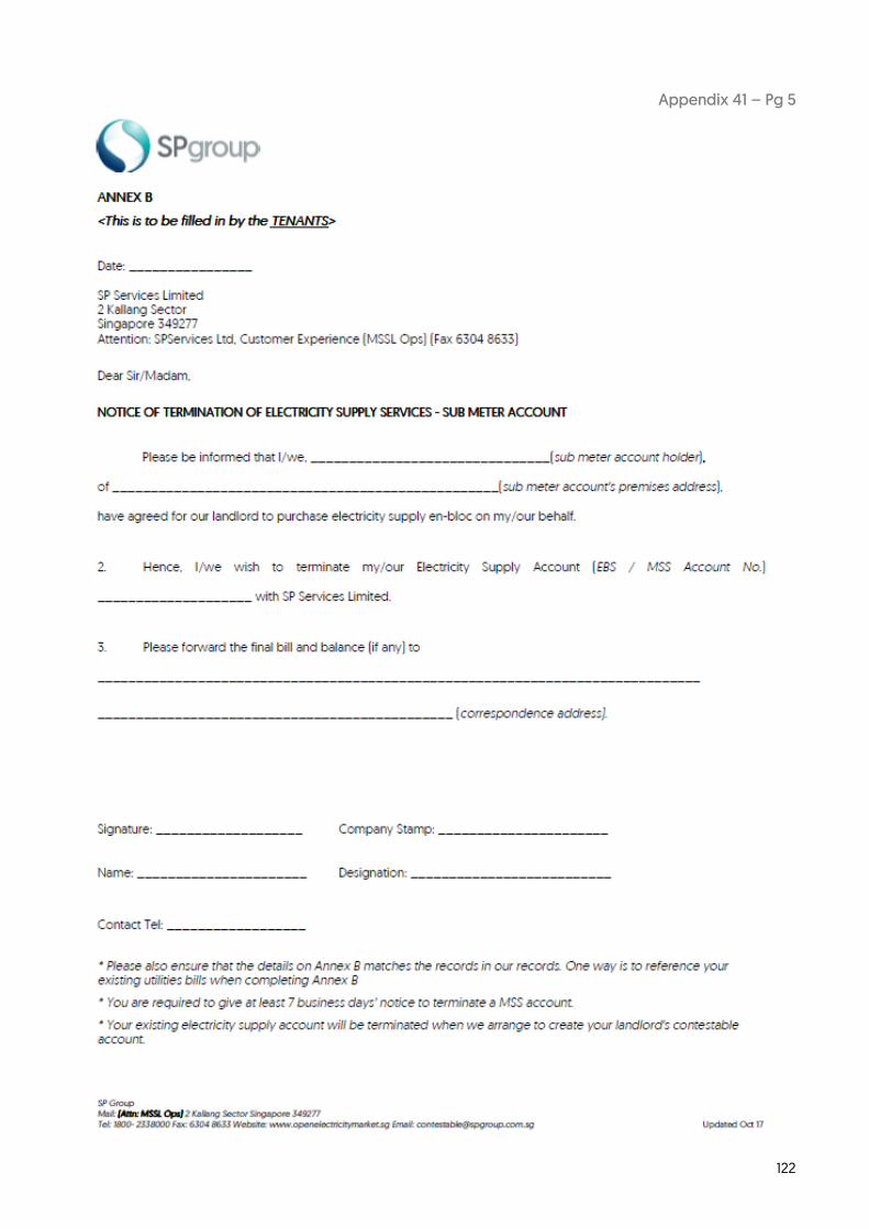
122
Appendix 41 – Pg 5

123
Appendix 41 – Pg 6

124
Appendix 41 – Pg 7

125
Appendix 41 – Pg 8

126
Appendix 41 – Pg 9
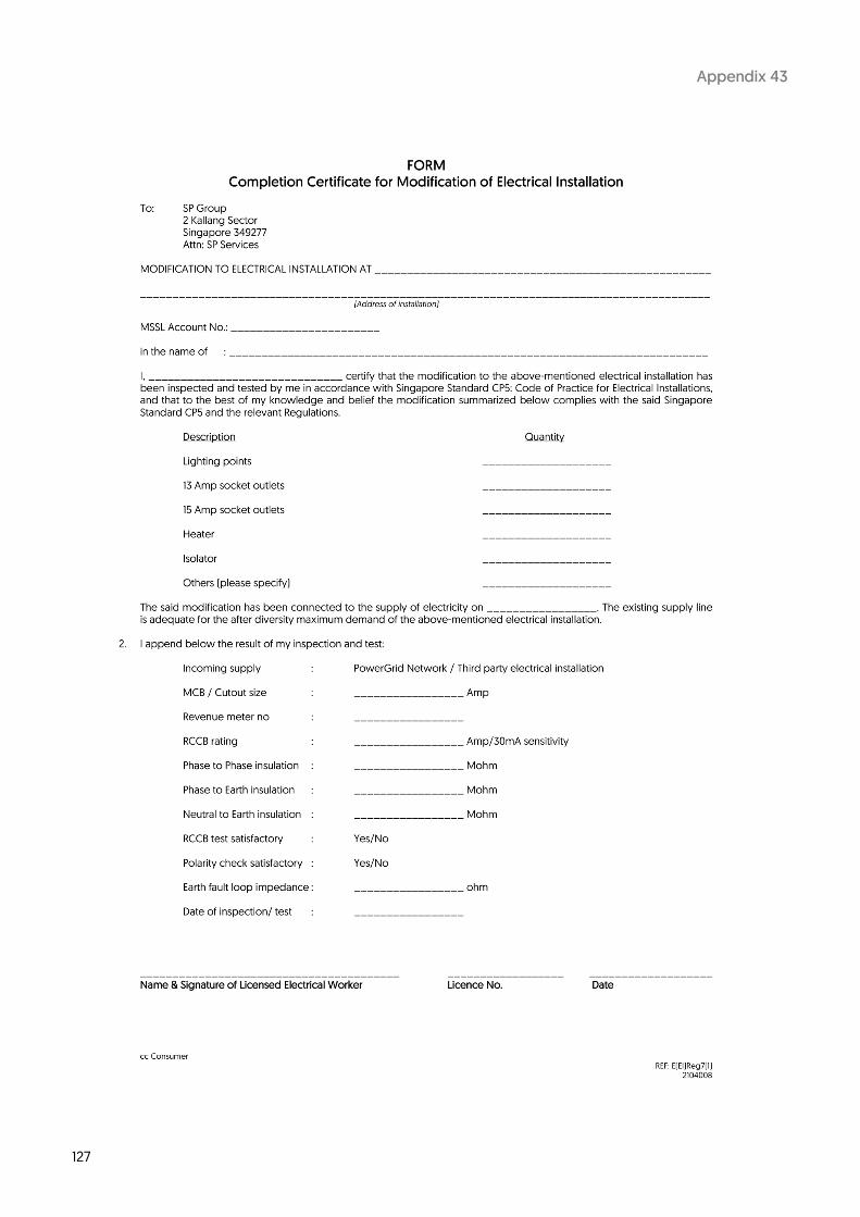
127
Appendix 43

128
Appendix 44

129
Appendix 45

130
Appendix 46 – Pg 1
TECHNICAL REQUIREMENTS OF DISTRIBUTED GENERATION AND NEW EXTRA / ULTRA HIGH
TENSION CONNECTION The technical requirements at the electricity supply network Point of Common Coupling (PCC) are highlighted below. Some of these requirements are covered in the Transmission Code issued by Energy Market Authority (EMA). The PCC is the point in the transmission system, electrically nearest to a connected person’s (refer to Transmission Code for definition) installation, at which other customers’ loads are, or may be, connected. Distributed Generation (DG) refers to embedded electricity generation of varying scale using conventional or alternative energy technology, e.g. Gas / Steam Turbine Generator, Solar Photovoltaic (PV), Fuel Cells, Biomass, etc. 1 Technical Requirements 1.1 Harmonics
The generation of harmonics by the DG or new EHT/UHT connection shall not cause the maximum voltage total harmonic distortion, individual odd voltage harmonic, and individual even voltage harmonic at the PCC to exceed the limits specified in Appendix F2.2 of the Transmission Code. These limits are indicated in the table below and include the existing levels of harmonic distortion at PCC.
Maximum Permissible Limit (%)
Parameter Voltage at PCC (kV)
0.23 / 0.4 6.6/22 66 230 / 400
Voltage Total Harmonic Distortion, VTHD 5 4 3 1.5
Individual Odd Voltage Harmonic 4 3 2 1
Individual Even Voltage Harmonic 2 2 1 0.5
1.2 Voltage Fluctuation including Flicker
The DG or new EHT/UHT connection shall not cause voltage fluctuation at the PCC to exceed 3% of the nominal voltage for step changes, as specified in Appendix F2.1 of the Transmission Code. The DG or new EHT/UHT connection shall also comply with Engineering Recommendation P28 – that is it shall not cause the short-term flicker severity value PST and the long-term flicker severity value PLT at the PCC to exceed 1.0 and 0.8 respectively.
1.3 Voltage Unbalance
The DG or new EHT/UHT connection shall not cause the maximum negative phase sequence component of phase voltage at the PCC to exceed 1%, as specified in Appendix F2.3 of the Transmission Code.
1.4 DC Injection
DC injection into the transmission system is deprecated. DC injection into the low voltage network at the PCC shall not exceed 0.5% of the inverter rated output current. If the DC injection at the PCC of an inverter based DG system deviates from this requirement, the Licensed Electrical Worker (LEW) shall submit technical justification (including effect on the transmission system) to SP PowerGrid (SPPG) for consideration. If applicable, the LEW shall also submit the specifications of mains isolation transformer or trip setting of DC injection detection device.
1.5 Voltage Disturbance
The design operation of the DG or new EHT/UHT connection shall take into consideration voltage disturbance phenomenon, such as voltage dip, in the transmission system. If their operations cannot tolerate any voltage fluctuations or distortions in supply, the connected person shall at their own cost provide power quality devices, as specified in Section 6.7.4 of the Transmission Code.

131
Appendix 46 – Pg 2
1.6 Abnormal Voltage and Frequency Response
Clause 1.6 is only applicable for DG connections. The DG shall cease to energize the transmission system: i. for faults on the service connection between the DG to the PCC; ii. prior to re-closure of the service connection of the transmission system circuit breaker; iii. if any phase of the transmission system is under or over voltage as detected at the PCC or at the
DG terminal. The range of abnormal operating voltages and the corresponding maximum disconnection time (i.e. operating time) are listed as follow:
Voltage Range
(% of base voltage)
Operating Time (second)
V < 50 0.6
50 ≤ V < 88 2.0
110 < V < 120 1.0
V ≥ 120 0.16
The DG shall be capable of sustained operation and remain connected to the transmission system if the frequency of the transmission system is within the range as specified in Appendix F6.2 of the Transmission Code.
Frequency Range
(Hz) Requirement
52 – 47.5 Continuous operation
47.5 – 47 Remain in operation for at least 20s each
time frequency falls below 47.5Hz

132
Appendix 46 – Pg 3 2 Submission of Compliance The LEW shall confirm compliance with regard to the technical requirements specified in Clause 1. This
shall include but is not limited to the following:
• Report confirming technical compliance • Supporting data on technical compliance (e.g. report of simulation study / type test / PQ
measurement, specifications and settings of generator / inverter, short circuit current contribution, etc.)
• Single Line Diagram (SLD) of the DG or new EHT/UHT connection up to the PCC level • Any other technical documentation deemed necessary by SPPG officer in the course of
clarification
The above shall be submitted to SPPG at the time of application to connect to the transmission system or within 2 weeks after clarification with SPPG officer. Technical justification shall be submitted to SPPG for consideration for deviation or non-compliance, if any.
2.1 PQ Simulation and Measurement Report
Clause 2.1 is applicable for all DG and new EHT/UHT connections. However, for Solar PV, it is only applicable if the system capacity is greater than 1MWac, or when deemed necessary by SPPG. Before the DG or new EHT/UHT connection, the LEW shall submit a simulation study or analysis to confirm compliance with the PQ requirements stipulated in Clause 1. The report shall indicate the harmonics parameters and voltage variation at PCC based on full load condition of the premise with consideration of the DG or new EHT/UHT connection. The report shall be submitted at least 2 months prior to the DG or new EHT/UHT actual connection. After the DG or new EHT/UHT connection, the LEW shall submit a PQ measurement report to confirm compliance with the PQ requirements specified in Clause 1. The PQ measurement report for DG connection shall comprise of 7 days pre-turn on measurement, which shall not be conducted more than 1 month before connection, and a 7 days post-turn on measurement, which shall include an off-on cycle of the DG. The off-on cycle duration shall be at least 1 hour but not more than 1 day. The PQ measurement report for new EHT/UHT connection shall comprise of 7 days post-turn on measurement after connection. The PQ measurement shall be conducted at the connected person’s incoming switchboard(s), and the report shall be submitted within 2 months from the date of the DG or new EHT/UHT connection.
3 PQ Measurement at the Connected Person’s Premises When deemed necessary by SPPG, SPPG may carry out measurements at the connected person’s
incoming switchboard(s) to verify the compliance report submitted under Clause 2. The connected person shall make provision at their incoming switchboard(s) to facilitate the connection of SPPG’s PQ monitor(s). All connection and disconnection of SPPG’s PQ monitor(s) from the switchboard(s) shall be carried out by the connected person’s LEW.
The monitoring schedule shall be jointly agreed by both parties and shall not be less than 7-day period. Before the commencement of this work, the connected person would have to agree with and sign SPPG’s testing / measurement services agreement.