how pigeons couple three-dimensional elbow and …lentinklab.stanford.edu/uploads/1510366770_2017...
TRANSCRIPT
on August 9, 2017http://rsif.royalsocietypublishing.org/Downloaded from
rsif.royalsocietypublishing.org
Research
Cite this article: Stowers AK, Matloff LY,
Lentink D. 2017 How pigeons couple three-
dimensional elbow and wrist motion to morph
their wings. J. R. Soc. Interface 14: 20170224.
http://dx.doi.org/10.1098/rsif.2017.0224
Received: 24 March 2017
Accepted: 11 July 2017
Subject Category:Life Sciences – Engineering interface
Subject Areas:biomechanics
Keywords:avian, wing morphing, skeletal mechanism,
functional morphology, design
Authors for correspondence:Amanda K. Stowers
e-mail: [email protected]
David Lentink
e-mail: [email protected]
Electronic supplementary material is available
online at https://dx.doi.org/10.6084/m9.
figshare.c.3832504.
& 2017 The Author(s) Published by the Royal Society. All rights reserved.
How pigeons couple three-dimensionalelbow and wrist motion to morphtheir wings
Amanda K. Stowers, Laura Y. Matloff and David Lentink
Department of Mechanical Engineering, Stanford University, 416 Escondido Mall, Stanford, CA 94305, USA
AKS, 0000-0003-4673-9524; LYM, 0000-0002-2033-2243; DL, 0000-0003-4717-6815
Birds change the shape and area of their wings to an exceptional degree, sur-
passing insects, bats and aircraft in their ability to morph their wings for a
variety of tasks. This morphing is governed by a musculoskeletal system,
which couples elbow and wrist motion. Since the discovery of this effect
in 1839, the planar ‘drawing parallels’ mechanism has been used to explain
the coupling. Remarkably, this mechanism has never been corroborated
from quantitative motion data. Therefore, we measured how the wing skel-
eton of a pigeon (Columba livia) moves during morphing. Despite earlier
planar assumptions, we found that the skeletal motion paths are highly
three-dimensional and do not lie in the anatomical plane, ruling out the
‘drawing parallels’ mechanism. Furthermore, micro-computed tomography
scans in seven consecutive poses show how the two wrist bones contribute
to morphing, particularly the sliding ulnare. From these data, we infer the
joint types for all six bones that form the wing morphing mechanism and
corroborate the most parsimonious mechanism based on least-squares
error minimization. Remarkably, the algorithm shows that all optimal
four-bar mechanisms either lock, are unable to track the highly three-
dimensional bone motion paths, or require the radius and ulna to cross
for accuracy, which is anatomically unrealistic. In contrast, the algorithm
finds that a six-bar mechanism recreates the measured motion accurately
with a parallel radius and ulna and a sliding ulnare. This revises our
mechanistic understanding of how birds morph their wings, and offers
quantitative inspiration for engineering morphing wings.
1. IntroductionThe ability of birds to change and streamline the shape of their wings from fully
extended to swept back distinguishes them from insects, bats, pterosaurs and
aircraft (figure 1). Wing morphing broadens the performance envelope of
birds, enabling them to fly faster, longer, and manoeuvre more effectively
[14–18]. Underlying the ability to morph is a musculoskeletal mechanism
first documented in an anatomical study of cadavers by Bergmann in 1839
[1]. This mechanism is thought to automatically flex and extend the wing like
a four-bar ‘drawing parallels’ [1–4] (figure 1b). This four-bar mechanism fol-
lows from the specialized skeletal arrangement of a bird wing; the upper arm
bone, the humerus, connects to two lower arm bones, the radius and ulna,
which connect via the wrist to the carpometacarpus (figure 1d ). In contrast to
other vertebrates (figure 1c), the parallel arrangement of the radius and ulna
coordinates elbow and wrist joint motions in birds. In non-flying vertebrates,
the radius and ulna are either rotated relative to the elbow along the longitu-
dinal axis of the humerus (e.g. approx. 908 in humans), or fused together
(e.g. ungulates). Even among flying vertebrates, birds and their ancestors
have a unique bone arrangement. Bats fly competently with a rudimentary
ulna that does not connect to the wrist [5]. Similarly, pterosaurs had a straight
radio-ulna, lacking the curvature and separation needed for a functional four-
bar mechanism [19]. Consequentially, birds can morph their wings more than

wingmorphing
(a) (b) 2D pin joints
3D spherical joints
humerus
radius
ulna
carpo- meta- carpus
wingextensioncentres
of rotation
radiale
markerclusters
ulnare
fruit bat
human
horse
pigeon
rudimentary
(c)
(d) (e)
Figure 1. Bird wing flexion and extension (morphing) is coordinated by a unique musculoskeletal structure that functions analogously to a mechanical linkage witha single degree of freedom. (a) The skeleton morphs the wing, which includes shape, span, sweep and area. (b) The current paradigm for explaining avian wingmorphing is the qualitative two-dimensional ‘drawing parallels’ mechanism in which the wing moves in a plane, and the elbow and wrist are coupled by a singledegree of freedom [1 – 6]. More recent computational and biological models assume a fused radius and ulna (drawn side-by-side in schematic) with three-dimen-sional spherical joints at the elbow and wrist [7 – 11], which simplifies elbow and wrist function and ignores three-dimensional coupling [12,13]. (c) Contrasting theventral view of the elbow joint in birds versus other vertebrates provides a clue about how the coupling works. Relative to a human, the bird radius and ulnaarticulation is rotated by 908 with respect to the longitudinal axis of the humerus. Therefore, bending the elbow pushes the radius along the ulna in birds, whichabducts the wrist. In contrast, other vertebrates’ radius and ulna articulation prevents this coupling. For instance, horses and other ungulates tend to have fusedforelimb bones. Bats, on the other hand, have a similar elbow configuration as birds, but have a rudimentary ulna, prohibiting elbow – wrist coupling. (d,e) In thisstudy, we measured the motion of pigeon bones using two techniques. (d ) First, we implanted clusters of three markers into each of the large (humerus, radius,ulna, carpometacarpus) bones and measured their motion using motion capture. (e) Second, we made micro-computed tomography scans of the forelimb in sevenposes (three shown) to determine the motion of all the bones including the radiale and ulnare wrist bones. The anchor indicates the stationary bone to show therelative motion of other bones.
rsif.royalsocietypublishing.orgJ.R.Soc.Interface
14:20170224
2
on August 9, 2017http://rsif.royalsocietypublishing.org/Downloaded from
bats and pterosaurs while continuously maintaining an aero-
dynamic profile [20]. This suggests that the precise
arrangement of the ulna and radius is important to under-
stand the evolution and function of avian flight. The
orientation of the radius and ulna is a striking feature present
even in the fossil remains of their dinosaur ancestors such as
Archaeopteryx [21].
In vivo and anatomical evidence demonstrates that the
coupling of elbow and wrist motion is critical for birds to fly
well. The ‘drawing parallels’ function of the radius and ulna
has been tested with in vivo surgical manipulations in pigeons
by Fisher [2], confirming elbow–wrist coupling. Furthermore,
injured birds lacking the ability to move their radius and ulna
relative to each other have difficulty flying. For instance, a
Mississippi kite (Ictinia mississippiensis) whose radius and
ulna fused together after a fracture could no longer extend
its wings or fly [22]. After surgical separation, the bird
regained its wing motion and flight abilities, indicating that
relative radio-ulnar motion is important. In a similar situation,
a barn owl (Tyto alba) whose radius was severely injured and
amputated had less wrist stability and was unable to fully
extend its hand wing [23]. Finally, Vazquez [12] showed in
an anatomical study of a pigeon wing how the specific attach-
ment of muscles, tendons and other connective tissues helps
create the coupled motion of the elbow and wrist joints.
Existing kinematic models of bird wings consider the
wing as either a planar four-bar mechanism with unspecified
parameters [1,4,5,12] or a specified open kinematic chain
starting at the shoulder with the radius and ulna fused as a
single bone [7–9,24]. These kinematic-chain studies offer
insight into joint angles, but do not consider more anato-
mically realistic mechanism types. Additionally, all existing
kinematic models ignore the role of the two wrist bones
[7–9], despite anatomical studies suggesting that the wrist
bones move and help coordinate hand motion [13]. More soph-
isticated quantitative models of musculoskeletal arm and wrist
motion exist only for humans [25–28]. These models have
been corroborated from the recorded kinematics of bones in
human cadavers by implanting markers and animating the
arm and hand through their degrees of freedom. Despite
their homology, human and bird forelimbs move completely
differently due to the morphological specialization visible in
the ventral view (figure 1c), which makes human models
irrelevant for understanding wing morphing. However, the
detailed motion capture and model corroboration techniques
can be miniaturized and adapted for a bird cadaver.
To test the hypothesis that the avian forelimb functions as
a four-bar mechanism in which wrist bone function can be
ignored [1–5], we measured wing skeletal kinematics in
pigeon cadavers. We measured humerus, radius, ulna and
carpometacarpus motion by motion tracking implanted
marker clusters, and related marker to bone motion and
bone shape using micro-computed tomography (mCT)
scans. We made additional mCT scans of the wing in seven
different poses to determine the relative motion of the four
bones with respect to the much smaller wrist bones, the
radiale and ulnare, since they were too small to be tracked
using motion capture. Using established joint optimization

rsif.royalsocietypublishing.org
3
on August 9, 2017http://rsif.royalsocietypublishing.org/Downloaded from
techniques, we found that a six-bar mechanism with a fully
functional wrist represents the most parsimonious kinematic
model of the avian forelimb. Subsequent mathematical
optimization demonstrated how four-bar models only rep-
resent the data well when the ulna and radius cross, which
is anatomically unrealistic. This not only revises our textbook
understanding of avian functional morphology [5,6,19], but
may critically inform fossil interpretation [29] and developmen-
tal studies [22,23]. Finally, the six-bar model offers the first
quantitative information for avian-inspired morphing wing
design [30–33].
J.R.Soc.Interface14:20170224
2. Material and methodsTo corroborate the mechanism underpinning bird wing morph-
ing, we measured the linear and rotational motion of wing
bones by animating the wings of three racing pigeon cadavers
(Columba livia; N ¼ 3; electronic supplementary material, table
S1). To objectively determine the most parsimonious forelimb
mechanism, we used a mathematical performance evaluation
based on error minimization, which requires high resolution of
all six degrees of freedom, including rotation about the long
axis of individual bones. This requirement ruled out in vivomethods based on high-speed fluoroscopy [10,34,35], because
the approximately 1 MP resolution of the image intensifiers is
too low. At present we find that these limitations can only be
overcome by cadaver studies, similar to those performed in
humans [26–28]. To achieve high fidelity measurements, we
used 12 MP resolution motion capture in concert with mCT
scans that offer the small error required for automated math-
ematical analysis. We used the motion capture system to
measure the relative positions of the four large wing bones
during a large number of continuous wing pose changes. We
complemented the bone motion recordings with mCT scans to
determine the bone shapes and the relative location of the bone
markers. Additionally, we scanned the wings in seven poses to
determine the motion of the much smaller wrist bones, which
could not be fitted with marker clusters.
2.1. High-resolution motion capture and micro-computed tomography scans of the wing skeleton
To track skeletal motion for each of the birds, we manually
morphed the right wing following the path of least resistance
while tracing out measured pigeon wing shapes (figure 1d,e).
The pigeons were fully intact except that covert feathers were
removed to allow for bone implantation of the motion tracking
markers. Unique marker clusters (electronic supplementary
material, table S2) were adhered to two carbon fibre posts
(1 mm) implanted ventrally in the keel of the sternum, humerus,
radius, ulna and carpometacarpus. Each marker cluster consisted
of three 2.4 mm diameter retroreflective markers (B&L Engineer-
ing) that were glued (BSI Super Gold) to scalene triangles made
from hollow carbon fibre rods (0.7 mm). We used Monte Carlo
simulations [36] to choose the distances between markers in
each cluster such that they were optimal for automatic identifi-
cation. To do this, we tested randomized lengths for each
cluster edge and tested how well the markers were identified
for each set. We then chose a case where identification was poss-
ible more than 98% of the time. With these uniquely identifiable
marker clusters in place, we measured bone motion by mounting
the pigeon cadaver to a custom support frame and moving the
wing through a series of three motion types actuated by hand
from the carpometacarpus. The three motion types were as fol-
lows: (i) wing flexion and extension traced through the three
wing outlines reported for a pigeon gliding at different speeds
[14,37], (ii) wrist circumduction with the elbow held by hand
at approximately mid-extension, and (iii) range of wrist rotation
with the elbow held by hand at approximately mid-extension.
Whereas only the flexion and extension cycle was used to deter-
mine the coupling between the elbow and wrist during
morphing, all three motion types were used to determine the
motion space of the wing joints. For each of the three motion
types, we conducted five trials, moving the wing by hand at
0.5 Hz per cycle for 25 s. We used a metronome to time wing
motion and ensure equivalent data between all pigeons. Six cam-
eras were used for tracking markers and a seventh for visual
marker verification in video mode (cameras: Qualisys, Oqus
7þ, 12 MP at 300 Hz, video mode at 30 Hz), with an accuracy
of approximately 0.1 mm (standard deviation of wand length,
tracking done by Qualisys Track Manager; QTM 2.11). After
motion tracking, we separated the right wing from the body
and measured the three-dimensional geometry of the skeleton
and relative positions of the implanted markers with mCT scans
(GE eXplore RS150, 47 mm voxels). Finally, we separated the left
wing to measure the relative positions of the four large wing
bones and the radiale and ulnare wrist bones in concert. To deter-
mine the relative motion of the bones from pose to pose, we mCT
scanned seven wing poses (Siemens Inveon mm-PET/CT 43 mm
voxels), segmented the bones and then aligned them to each
position manually in Meshlab (v. 1.3.3).
2.2. Calculation of bone positions and joint locationsUsing the motion capture data, we exported bone trajectories
into Matlab (The Mathworks, R2015b) and filtered the position
data with a fourth order low-pass Butterworth filter at 8 Hz.
We defined the flexion–extension cycles using the periodic
motion of the most distal point on the carpometacarpus. Each
flexion–extension cycle lasted approximately two seconds, so
we resampled the data to 500 points per cycle for consistency.
We automatically generated the mechanisms using the cycles
for which all markers were successfully tracked for at least 80%
of the time (n ¼ 83), and subsequently validated these mechan-
isms using cycles for which all markers successfully tracked
100% of the time (n ¼ 37 total; n ¼ 14 for pigeon 1, n ¼ 9 for
pigeon 2, n ¼ 14 for pigeon 3). By tracking three markers on
each of the humerus, radius, ulna and carpometacarpus, we
determined all rotations as well as translations of these bones
relative to each other. For the radiale and ulnare, orientation
was determined using the seven mCT-scanned poses. To achieve
consistency in our numerical analysis and to compare fairly
between pigeons, we defined theoretical markers located at the
centre of mass and 30 mm along the principal axes of each
measured bone and used those for calculations (calculated
assuming uniform density in Meshlab v. 1.3.3), as shown in
electronic supplementary material, figure S1.
2.3. Mechanism corroboration via error minimizationWe corroborated mechanisms based on the motion capture and
mCT data using a custom programmed (The Mathworks,
Matlab 2015b) least-squares method to determine the centres
and axes of rotation for each model bone [38]. We constructed
the joints between the more distal ‘moving’ bone, m, and the
more proximal ‘grounded’ bone, g, as follows. For each frame,
k, computational markers are located on the bone at v1¼ [0, 0,
0]T, v2¼ [0, 30, 0]T, v3¼ [0, 0, 30]T, v4¼ [30, 0, 0]T, shown in elec-
tronic supplementary material, figure S1. These positions are
identifiable across pigeons. They also make the calculation of
the centres of rotation less sensitive to errors in marker measure-
ment, because at least three of these points are not expected to lie
close to a line intersecting with the centre of rotation. The pos-
ition vector pi,o,k corresponds to the centre of mass (o; origin),
and the unit vectors pi,x,k, pi,y,k, pi,z,k correspond to the unit
20 mm
(a)
(b)
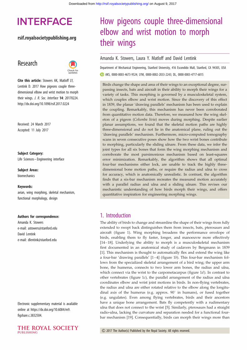
Figure 2. Wing skeletal motion does not coincide with the anatomical planeand is non-planar during flexion and extension. (a) Looking from the ventralview with the humerus fixed (anchored), we see the motion paths of thebone centres of mass (coloured lines) move mediolaterally as expected.(b) Looking anteriorly ( from the tail), we see how the carpometacarpusmoves significantly out of the anatomical plane defined by the humerusand radius/ulna. Electronic supplementary material, video S1, shows an ani-mation of this motion from both viewpoints. Coloured lines represent themotion paths of the bone centres of mass in both panels.
palmar–90°
–45°
90°
180°
human
pigeon
90°dorsal
radial adduction
ulnar abduction
0°
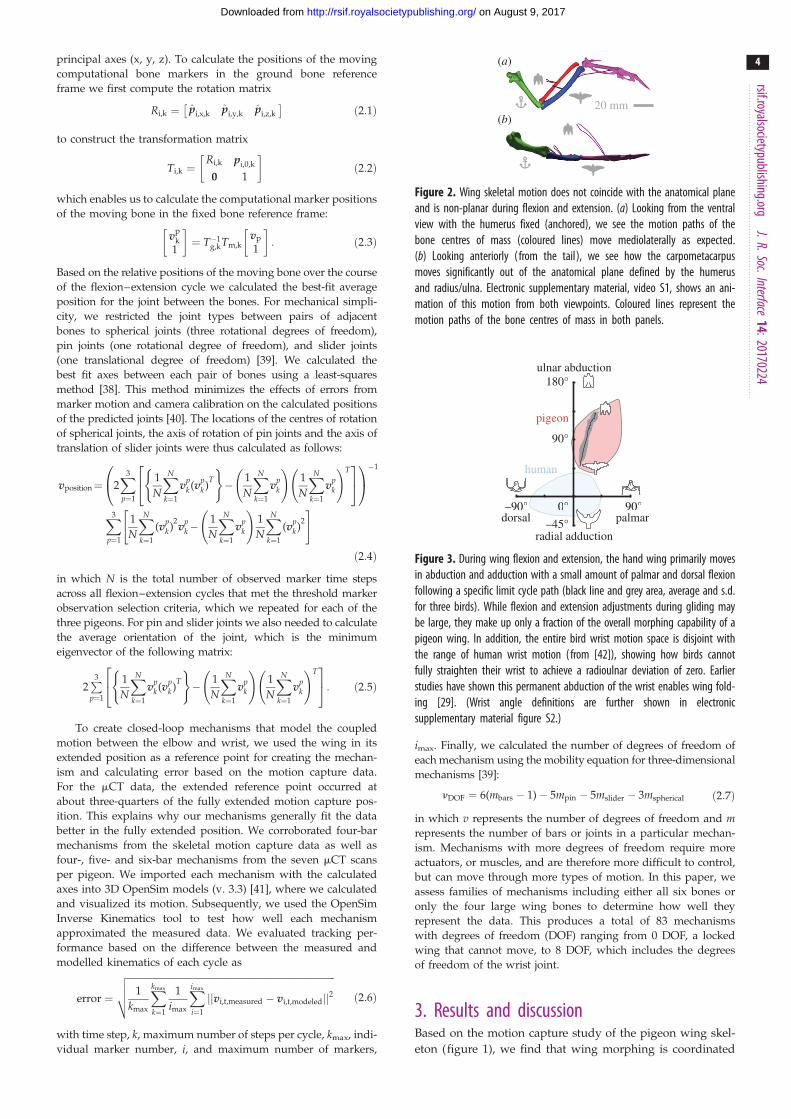
Figure 3. During wing flexion and extension, the hand wing primarily movesin abduction and adduction with a small amount of palmar and dorsal flexionfollowing a specific limit cycle path (black line and grey area, average and s.d.for three birds). While flexion and extension adjustments during gliding maybe large, they make up only a fraction of the overall morphing capability of apigeon wing. In addition, the entire bird wrist motion space is disjoint withthe range of human wrist motion (from [42]), showing how birds cannotfully straighten their wrist to achieve a radioulnar deviation of zero. Earlierstudies have shown this permanent abduction of the wrist enables wing fold-ing [29]. (Wrist angle definitions are further shown in electronicsupplementary material figure S2.)
rsif.royalsocietypublishing.orgJ.R.Soc.Interface
14:20170224
4
on August 9, 2017http://rsif.royalsocietypublishing.org/Downloaded from
principal axes (x, y, z). To calculate the positions of the moving
computational bone markers in the ground bone reference
frame we first compute the rotation matrix
Ri,k ¼ pi,x,k pi,y,k pi,z,k
� �ð2:1Þ
to construct the transformation matrix
Ti,k ¼Ri,k pi,0,k
0 1
� �ð2:2Þ
which enables us to calculate the computational marker positions
of the moving bone in the fixed bone reference frame:
vpk
1
� �¼ T�1
g,kTm,kvp
1
� �: ð2:3Þ
Based on the relative positions of the moving bone over the course
of the flexion–extension cycle we calculated the best-fit average
position for the joint between the bones. For mechanical simpli-
city, we restricted the joint types between pairs of adjacent
bones to spherical joints (three rotational degrees of freedom),
pin joints (one rotational degree of freedom), and slider joints
(one translational degree of freedom) [39]. We calculated the
best fit axes between each pair of bones using a least-squares
method [38]. This method minimizes the effects of errors from
marker motion and camera calibration on the calculated positions
of the predicted joints [40]. The locations of the centres of rotation
of spherical joints, the axis of rotation of pin joints and the axis of
translation of slider joints were thus calculated as follows:
vposition¼ 2X3
p¼1
1
N
XN
k¼1
vpk (v
pk )
T
( )� 1
N
XN
k¼1
vpk
!1
N
XN
k¼1
vpk
!T24
35
0@
1A�1
X3
p¼1
1
N
XN
k¼1
(vpk )
2v
pk�
1
N
XN
k¼1
vpk
!1
N
XN
k¼1
(vpk )
2
" #
ð2:4Þ
in which N is the total number of observed marker time steps
across all flexion–extension cycles that met the threshold marker
observation selection criteria, which we repeated for each of the
three pigeons. For pin and slider joints we also needed to calculate
the average orientation of the joint, which is the minimum
eigenvector of the following matrix:
2P3p¼1
1
N
XN
k¼1
vpk (v
pk )
T
( )� 1
N
XN
k¼1
vpk
!1
N
XN
k¼1
vpk
!T24
35: ð2:5Þ
To create closed-loop mechanisms that model the coupled
motion between the elbow and wrist, we used the wing in its
extended position as a reference point for creating the mechan-
ism and calculating error based on the motion capture data.
For the mCT data, the extended reference point occurred at
about three-quarters of the fully extended motion capture pos-
ition. This explains why our mechanisms generally fit the data
better in the fully extended position. We corroborated four-bar
mechanisms from the skeletal motion capture data as well as
four-, five- and six-bar mechanisms from the seven mCT scans
per pigeon. We imported each mechanism with the calculated
axes into 3D OpenSim models (v. 3.3) [41], where we calculated
and visualized its motion. Subsequently, we used the OpenSim
Inverse Kinematics tool to test how well each mechanism
approximated the measured data. We evaluated tracking per-
formance based on the difference between the measured and
modelled kinematics of each cycle as
error ¼
ffiffiffiffiffiffiffiffiffiffiffiffiffiffiffiffiffiffiffiffiffiffiffiffiffiffiffiffiffiffiffiffiffiffiffiffiffiffiffiffiffiffiffiffiffiffiffiffiffiffiffiffiffiffiffiffiffiffiffiffiffiffiffiffiffiffiffiffiffiffiffiffiffiffiffiffiffiffiffiffiffiffiffiffiffiffiffiffi1
kmax
Xkmax
k¼1
1
imax
Ximax
i¼1
jjvi,t,measured � vi,t,modeledjj2vuut ð2:6Þ
with time step, k, maximum number of steps per cycle, kmax, indi-
vidual marker number, i, and maximum number of markers,
imax. Finally, we calculated the number of degrees of freedom of
each mechanism using the mobility equation for three-dimensional
mechanisms [39]:
nDOF ¼ 6(mbars � 1)� 5mpin � 5mslider � 3mspherical ð2:7Þ
in which v represents the number of degrees of freedom and mrepresents the number of bars or joints in a particular mechan-
ism. Mechanisms with more degrees of freedom require more
actuators, or muscles, and are therefore more difficult to control,
but can move through more types of motion. In this paper, we
assess families of mechanisms including either all six bones or
only the four large wing bones to determine how well they
represent the data. This produces a total of 83 mechanisms
with degrees of freedom (DOF) ranging from 0 DOF, a locked
wing that cannot move, to 8 DOF, which includes the degrees
of freedom of the wrist joint.
3. Results and discussionBased on the motion capture study of the pigeon wing skel-
eton (figure 1), we find that wing morphing is coordinated

second digitmotion
ulnareslides
radialerotates radiale
rotates
ulnarerotates
wingextension
(a) (b)
(c) (d)
Figure 4. During wing flexion and extension, the second digit can move independently while the wrist bones rotate and slide in concert with the connecting bones.We show the bones here in three (out of seven) positions obtained with mCT scans (other pigeons shown in electronic supplementary material, figure S3). (a) As thewing extends, the elbow and wrist move in a coordinated fashion. (b) The second digit can move independently up to 308, enabling refinement of wingtip motion.(c) Relative to the lower radius and ulna, the ulnare primarily slides along the ulna while the radiale remains relatively stationary. (d ) Both the radiale and ulnareprimarily rotate about the head of the carpometacarpus.
rsif.royalsocietypublishing.orgJ.R.Soc.Interface
14:20170224
5
on August 9, 2017http://rsif.royalsocietypublishing.org/Downloaded from
by three-dimensional bone motion beyond the anatomical
plane, defined as the plane spanning the humerus and the
radius/ulna. In the fully extended wing position, the
humerus, radius, ulna and carpometacarpus lie primarily in
this plane. At the maximally flexed position, the plane
spanned by the radius/ulna and the carpometacarpus devi-
ates from the anatomical plane by about 458. However, as
the wing flexes, the large wing bones deviate from
the best fit wing motion plane (figure 2) by an average of
5.0+0.7 mm for all three pigeons. This deviation means
that a planar mechanism could have a minimum error of
5+0.7 mm, showing that even the best possible two-dimensional
mechanism would perform worse than three-dimensional
mechanisms. Therefore, the planar four-bar mechanism para-
digm, inferred from anatomical studies since 1839 [1–3,5,6],
does not represent measured skeletal motion, which is
highly three-dimensional. To better quantify the full range
of motion of the wing, we measured the range of possible
motion of the carpometacarpus relative to the radius/ulna,
both in and out of the anatomical plane (figure 3; angles
defined in electronic supplementary material, figure S2).
The wing flexion and extension adjustments during gliding
represent a well-defined narrow path within the full range
of potential wrist motion (shaded area). The remainder of
the motion space is available for wing control adjustments,
wing flapping, or folding the wings against the body. For
comparison, we also plotted the range of motion for a
human wrist [42] in figure 3. This illustrates how bird
wrists have permanent ulnar abduction with the hand
angled towards the ulnar side of the forearm, [29] compared
to the human wrist [42]. This provides wrist stabilization [13]
and locks the wing in place during lift generation so it can
bear the extreme load, which is proportional to body
weight. Together these adaptations explain why human
and bird wrist motion spaces do not overlap, despite the
fact that the full wrist motion space of a bird has about the
same area as that of a human. The bird flexion–extension
limit cycle only occupies a narrow region of wrist motion
space; the additional area facilitates palmar folding during
flapping flight and fully folding the wing to the body. In con-
cert, these quantitative observations of three-dimensional
bird skeletal motion explain why a new data-driven mechan-
ism is needed to underpin the three-dimensional skeletal
kinematics of bird wing morphing.
A six-bar model of the wing skeleton including the two
wrist and four main wing bones represents the measured
three-dimensional skeletal kinematics and morphology well.
We created this mechanism by combining anatomical obser-
vations from mCT scans with simplified joint models
defined and evaluated using least-squares error minimization
(Material and methods). This process is similar to the one
developed for analysing and modelling the measured skeletal
motion in biomedical studies of the human arm [26]. We initi-
alized our model by integrating the measured relative motion
of the two wrist and four main wing bones in the seven mCT
scans that span the wing flexion–extension cycle (figure 4),
combined with earlier qualitative studies [9,12]. Based on
this evaluation, we hypothesize the following possible joint
types between the wing bones: two spherical joints connect
the distal end of the humerus with the proximal end of the
radius and ulna, a pin joint connects the distal radius with
the radiale, a slider joint connects the distal ulna with the
ulnare, and two spherical joints connect the radiale and
ulnare with the proximal end of the carpometacarpus.
These joints together comprise 8 DOF for the wing. The
associated lengths of all six bars as well as the locations,
orientations and motions of the joints, figure 5a, were calcu-
lated using a modified least-squares algorithm (Material
and methods) [43] for each of the three pigeons. To account
for differences in bone length between the three individuals,
we created topologically equivalent models that were scaled
to fit each pigeon. For each mechanism, we quantified the
mechanism prediction error over the whole flexion–extension
cycle (figure 5b), which remains fairly constant and is of simi-
lar magnitude across all flexion and extension cycles of each
wing. This corroborated six-bar model predicts anatomically
reasonable locations for the joint locations and the lengths of
the connecting bars, as well as joint motion paths of the four

2
(mm)–2
0˚45˚
90˚30˚60˚
flexion–extension
devi
atio
ner
ror(
mm
)
0
10
20
1 10
(a)
(b)
Figure 5. By applying error minimization to the motion capture and mCTscan data, we corroborated a six-bar mechanism that accurately representsthe three-dimensional coupled motion of wing morphing. The mechanismuses four spherical joints to connect the humerus and carpometacarpusand a pin (radiale) and slider joint (ulnare) for the wrist bone joints. Inthis mechanism, the radiale and ulnare are single degree of freedomextensions of the radius and ulna respectively. (a) Using the six-barmodel, we calculated all joints required to replicate the measured CT scandata using a least-squares error minimization algorithm. The circular plotsshow the motion space for a spherical joint, with the centre representingthe centre of rotation. Straight lines through the centre represent the bestfit pin joint, while deviation from this represents spherical joints. Longaxis rotation is not shown (involved in wing pronation and supination,which we did not study). Spherical joints at the elbow move more similarlyto pin joints compared to those connecting the carpometacarpus to the wrist.The radiale and ulnare each move less than the large bones, with less than4 mm total ulnare excursion during a typical cycle. (b) The root mean squareerror of the simulated markers (see Material and methods, equation (2.6)) isshown over the flexion and extension cycle for each of the three pigeons andis nearly constant (error calculation based on motion capture data of the fourlarge bones; jumps are due to meeting convergence criteria in the error mini-mization scheme). Thick coloured lines indicate average results for eachpigeon (red, pigeon 1; green, pigeon 2; blue, pigeon 3), individual tracesare indicated with semitransparent thinner lines. The thick black linesshow the average over all three pigeons and the grey areas representstandard deviation. The schematic is based on pigeon 1.
no wrist just radiale just ulnare full wrist0
5
10
15
20
RM
S er
ror(
mm
)
****** ************ **
Figure 6. Using a least-squares error minimization algorithm, we find thatincluding the wrist bones in the mechanism is essential to replicate themeasured skeletal motion accurately. We calculated the RMS errors for all per-mutations in which we change spherical joints into pin joints, while keepingsufficient degrees of freedom to not lock the mechanism (shown as greycircles). From this we found that the four spherical joints in our model( figure 5) are essential for minimal RMS error (coloured symbols) regardlessof how we simplified the wrist. To determine if modelling wrist motion isessential, we fused both wrist joints (no wrist), the ulnare (just radiale),and the ulnare (just radiale) at their fully extended location and comparedit with the full wrist model ( figure 5). Using a t-test, we find that for allthree pigeons a sliding ulnare significantly improves the ability of a mechan-ism to replicate measured skeletal motion, and that the combination of theradiale and ulnare reduces RMS error ( p , 0.001; see details in table 1).Sketches denote line diagrams of each mechanism manipulation, which aredrawn to scale based on pigeon 1. The three columns for each mechanismindicate the three different pigeons tested (red, green and blue are used fortheir corresponding minimal RMS error mechanisms). Definitions for mechan-isms shown on top: solid line, bar; solid circle, 3 DOF spherical joint; opencircle, 1 DOF pin joint; double arrow, 1 DOF slider joint. See electronic sup-plementary material, video S2, for a comparison of the fused four-bar ‘nowrist’ and six-bar ‘full wrist’ mechanism.
rsif.royalsocietypublishing.orgJ.R.Soc.Interface
14:20170224
6
on August 9, 2017http://rsif.royalsocietypublishing.org/Downloaded from
spherical, one pin and one slider joints (figure 5). The best-fit
joint paths over each sphere show that the elbow joints
behave relatively closely to pin joints, with predominant
elbow flexion–extension. In contrast, the joint between the
wrist bones and the carpometacarpus requires the ranges of
motion provided by a spherical joint, due to significant
wrist abduction/adduction and palmar/dorsal motion.
Additionally, the relative radius–radiale, and ulna–ulnare
motion is small, which explains why a pin and slider joint
are sufficient to approximate their degrees of freedom
(figure 4). The six bars and the six measured joint motion
paths combined define the flexion and extension cycle of
the pigeon wing, during gliding, with a quasi-single degree
of freedom (figure 5). Based on this six-bar model, we
adjusted the number of bars and joint types to establish the
most parsimonious model that can accurately represent the
measured skeletal motion and anatomy.
Systematic tests show that a simplified six-bar skeletal
model of the pigeon wing, with a reduced number of bars
and degrees of freedom, fits the data worse than the original
six-bar model. We tested simpler models not only to assess
parsimony, but also to verify earlier models that have
suggested that the wrist bones can be ignored [1–3,5,7,
9–11] and that the bones connect like pin joints at the
elbow [7,9]. We therefore simplified the corroborated six-
bar model to see how earlier mechanism choices affect
tracking performance and morphological realism. We found
that converting one or more spherical joints into pin joints
increased the RMS error of all simplified mechanism permu-
tations tested (grey dots in figure 6). The effect of constraining
motion to a pin joint is not equal for all joints. Generally
speaking, constraining the elbow caused less increase in
error than constraining the wrist; however, the best perform-
ance occurs with spherical joints, because they track the
three-dimensional motion out-of-anatomical-plane better
(figures 2, 4 and 5). To determine if simplifying the wrist
affects tracking performance, we first removed the radiale

(b)
(a)
0
10
20
erro
r(m
m)
(a)
(b)
1 10
sphere
pin
(c)
Figure 7. The ‘drawing parallels’ paradigm cannot explain bird skeletal motion during wing morphing, because the four-bar mechanisms that fit the three-dimen-sional motion data require the radius and ulna bars to cross, which is anatomically unrealistic. (a) The pin joints of a ‘drawing parallels’ mechanism lock along thehighly three-dimensional skeletal motion paths of wing flexion and extension. We anchored the humerus to show relative bone motion. (b) A four-bar mechanismwith spherical joints replicates the bone motion accurately. However, the error minimization requires the mechanism to cross, which does not match the scannedskeletal motion data. (c) The RMS error of the locked (a) and crossed (b) four-bar mechanisms over the flexion – extension cycle. The mechanisms approximatemotion best at the fully extended position because the mechanism creation algorithm uses that as the starting position. In both (a) and (b), coloured bones indicatefour-bar mechanism motion based on error minimization, grey bones indicate measured motion.
Table 1. Including the wrist bones in the corroborated skeletal mechanism is essential for tracking the measured bone motion accurately. Including wrist bonesin the mechanism decreases the kinematics tracking error for each pigeon statistically significantly. Additionally, paired sample testing rejects the hypothesis thatthe wrist bones have no effect with p , 0.001 (t-test, the 95% CI of decrease in error by incorporating wrist bones is 1.5 – 2.3 mm). Including the ulnaresignificantly improves the wing mechanism performance for each pigeon, while including the radiale only improves wing mechanism performance for onepigeon. Therefore, we conclude that the motion of the ulnare is important for understanding bird wing flexion – extension, while the role of the radiale is lessimportant. (Parameter n is the number of wing flexion – extension cycles with 100% tracking, which we used for mechanism validation.)
nlocked wristRMS error (mm)
just radialeRMS error (mm)
just ulnareRMS error (mm)
full wristRMS error (mm)
pigeon 1 14 4.6+ 0.8 4.4+ 0.8 2.2+ 0.2*** 2.2+ 0.2***
pigeon 2 9 2.9+ 0.1 2.8+ 0.1 2.7+ 0.1** 2.6+ 0.1***
pigeon 3 14 6.6+ 0.9 4.3+ 0.5*** 4.5+ 0.6*** 4.2+ 0.5***
**p � 0.01, ***p � 0.001.
flexed carpometacarpus
carpometacarpusin extended position
carpometacarpuswithout ulnare motion
qd
shifted centre of rotation
d
dtan q
2( )
Figure 8. The shifted centre of rotation in a crossed four-bar simulates theeffect of a slider joint, the ulnare, which enables it to fit the measured skel-etal motion data better. We demonstrate this mathematically using theReuleaux method, which is a geometric construction to find the centre ofrotation in two dimensions [44]. By only rotating the carpometacarpus(light pink), the centre of rotation is approximately where expected—atthe end of the ulna and inside the condyle of the carpometacarpus. Ifinstead, the carpometacarpus both rotates and translates (dark pink), thenthe centre of rotation is shifted anterior of the condyle of the carpometacar-pus by a distance of d/tan(u/2). This combination of rotation and translationcorresponds to the effect of the sliding ulnare in the pigeon wing, whichpushes the centre of rotation out.
rsif.royalsocietypublishing.orgJ.R.Soc.Interface
14:20170224
7
on August 9, 2017http://rsif.royalsocietypublishing.org/Downloaded from
and ulnare joints by fusing them with the radius and ulna
respectively in their fully extended position. The tracking per-
formance of this four-bar model (no wrist joints, 6 degrees of
freedom) is significantly worse (table 1, figure 6); therefore,
the wrist joints serve a measurable function. To test if both
wrist joints contribute equally to the improved tracking per-
formance, we released their degree of freedom individually
in the four-bar model with the fused wrist ( just radiale or
just ulnare, figure 6). This test shows that including the
ulnare joint significantly improves tracking performance of
the measured skeletal motion for each pigeon, while the
radiale only provides significant improvement in one
pigeon. This makes sense because the rotation of the radiale
around the end of the radius contributes only a second
rotation, while the ulnare contributes sliding motion along
the end of the ulna, which shifts the centre of rotation with
the carpometacarpus (figure 4) and extends the wingspan.
While the simplified six-bar model with fused wrist joints
indicates that wrist bones are necessary to accurately model
wing morphing, it is possible to create better four-bar mech-
anisms by optimizing their joint locations and types directly.
Remarkably, if we directly optimize a four-bar mechanism
from the motion capture data, the resulting mechanism
requires the radius and ulna to cross. This simulates the
wrist function, but is anatomically unrealistic. The crossing
mechanism connects the optimized joint locations with the

0
5
10
15
20
RM
S er
ror
(mm
)
4 pin0 ball
3 pin1 ball
2 pin2 ball
1 pin3 ball
0 pin4 ball
fullwrist
(b)(a) anatomically infeasible
notstatistically
different
0˚45˚
90˚30˚60˚
flexion–extension
devi
atio
n
Figure 9. Flexion and extension of the avian wing skeleton is best modelled by a six-bar mechanism, because all corroborated four-bar mechanisms are locked orrequire the ulna and radius to cross for minimal RMS error—regardless of all possible permutations of spherical versus pin joints. (a) A crossed four-bar mechanismwith four spherical joints best represents the measured skeletal motion based on least-squares error minimization. The anatomically unrealistic crossing of the ulnaand radius places the centre of rotation of the ulna – carpometacarpus joint in front of the radius – carpometacarpus joint which simulates the effect of the slidingulnare wrist bone. The associated spherical joint motion paths are more similar for all three pigeons than found for the anatomically realistic six-bar mechanism(figure 5). (b) Evaluation of all possible combinations of pin and spherical (ball) joints shows that four-bar mechanisms are either locked or require the radius andulna to cross to accurately replicate the measured skeletal motion. In contrast, the least-squares error minimization algorithm requires the radius and ulna of thesix-bar mechanism to be parallel, which is not only anatomically realistic, but also results in the lowest RMS error. Remarkably, the crossed four-bar mechanismwith four spherical joints can achieve a similarly low RMS error as the six-bar mechanism with no statistical difference when pooled (pooled, n ¼ 3; individuallyp ¼ 0.44 for pigeon 1, p ¼ 0.03 for pigeon 2, p ¼ 0.16 for pigeon 3).
rsif.royalsocietypublishing.orgJ.R.Soc.Interface
14:20170224
8
on August 9, 2017http://rsif.royalsocietypublishing.org/Downloaded from
shortest possible links (figure 7b), aligning the ulna and
radius along the links of this virtual mechanism when apply-
ing parsimony. An even simpler three-dimensional four-bar
mechanism with four pin joints is unable to move along the
bone motion paths (figure 7a,c). The pin joints lock the mech-
anism, because it has negative two degrees of freedom along
the highly three-dimensional bone motion paths (figure 2). In
contrast, a four-bar mechanism with four spherical joints
(figure 7b) tracks the measured skeletal kinematics well
(figure 7c). However, the least-squares error minimization
finds that the joint centre connecting the ulna with the
carpometacarpus needs to be positioned anterior to the
radius–carpometacarpus joint, forcing the ulna and radius
to crosses. Additionally, we determined that the optimized
centre of rotation of the ulna no longer lies within the condyle
of the carpometacarpus. These outcomes of the least-squares
error minimization are thus anatomically unrealistic. To
understand this, we further analysed this solution mathemat-
ically and found that the crossing links simulate the function
of the sliding ulnare in the wrist. When the ulnare slides
along the ulna, it causes the average centre of rotation
between the ulna and carpometacarpus to shift anteriorly
(figures 8 and 9a). The sliding motion of the ulnare is
confirmed by the mCT scans (figure 4). Further, for all permu-
tations of pin and spherical joint combinations we find that
the optimized four-bar mechanism either locks or crosses
(figure 9b). This shows how all hypothesized four-bar mech-
anisms in the literature lock in three dimensions (because
they include only pin joints), result in anatomically unrealistic
mechanisms that simulate the wrist (optimized spherical
joints) or are imprecise (four-bar model based on anatomy
with fused wrist joints) when recreating measured skeletal
motion. Therefore, we conclude that the wrist bones are an
integral part of the measured wing morphing mechanism,
which requires a full-fledged six-bar mechanism to model
avian wing motion and anatomy in concert (electronic sup-
plementary material, table S4). It has not escaped our
attention, however, that the crossed four-bar mechanism is
as accurate (figure 9b) and potentially simpler to embody in
engineering morphing wing design and multiphysics simu-
lations of avian flight (electronic supplementary material,
table S5). However, the six-bar mechanism is a better choice
if precise joint centres and moment arms between the bones
are needed. Future studies could test how well the degrees
of freedom in the joints of the six-bar mechanism capture
wing pronation and supination, flapping motion, as well as
fully folding the wing against the body.
4. ConclusionBased on detailed wing morphology and motion
measurements for three pigeons, we corroborated a three-
dimensional six-bar mechanism that models the morphing
function of the avian wing skeleton. The two additional
bars, compared to the four-bar paradigm, are essential to
model wrist function. The model is robust to all simplifying
manipulations: inclusion of three-dimensional spherical
joints to form the elbow at the humerus and the wrist at the
carpometacarpus, as well as the additional two-dimensional
degrees of freedom wrist joints with the radius and ulna,
are essential to recreate the measured function. Both the six-
bar manipulations and the four-bar optimizations point at
the pivotal role of the sliding ulnare to interpret wrist function
and recreate avian wing morphing motion. Therefore, the ubi-
quitous ‘drawing parallels’ explanation of avian forelimb
function in textbooks on animal flight [5,19] and functional
morphology [6], as well as natural history museum displays
(e.g. the Smithsonian National Museum of Natural History,
2016) need to be revised. The new six-bar model with a func-
tional wrist can help interpret fossils [29] and bird
development [45]. It may also help inform more effective
treatment plans for injured birds [22,23]. Finally, both the bio-
logically realistic six-bar and the anatomically unrealistic

rsif.royalsocietypublishing.org
9
on August 9, 2017http://rsif.royalsocietypublishing.org/Downloaded from
crossed four-bar model offer quantitative inspiration for
engineering morphing wing design [30–33].
Data accessibility. Data are available at http://purl.stanford.edu/tw552tz7895.
Authors’ contributions. A.K.S. designed the study, made experimentalmeasurements, performed data analysis and drafted the manuscript.L.Y.M. made experimental measurements and helped edit the manu-script. D.L. designed the study and drafted the manuscript. Allauthors gave final approval for publication.
Competing interests. We declare we have no competing interests.
Funding. This project was supported by Air Force Office of ScientificResearch award number FA9550-16-1-0182, Office of Naval Research(ONR) Multidisciplinary University Research Initiative (MURI) grantN00014-09-1051, and the KACST Center of Excellence for Aeronauticsat Stanford. A.K.S. was supported by the Department of Defense(DoD) through the National Defense Science & Engineering GraduateFellowship Program (NDSEG). D.L. was supported by NSF CAREERAward 1552419.
Acknowledgements. CT scans were performed in the Stanford Center forInnovation in In-Vivo Imaging (SCI3). We thank members of the Len-tink Lab for feedback on the experiment and figures. We also thankthe anonymous reviewers for their helpful feedback.
J.R.Soc.
ReferencesInterface14:20170224
1. Bergmann C. 1839 Uber die Bewegungen vonRadius und Ulna am Vogelflugel. Arch. Anat.Physiol. wiss Med. 6, 296 – 300.
2. Fisher HI. 1957 Bony mechanism of automaticflexion and extension in the pigeon’s wing. Science126, 446. (doi:10.1126/science.126.3271.446)
3. Coues E. 1871 Mechanism of flexion and extensionin birds’ wings. Am. Nat. 5, 513 – 514. (doi:10.1086/270813)
4. Nachtigall W. 1985 Warum die Vogel fliegen. Raschund Rohring.
5. Norberg UMU. 1990 Vertebrate flight, ch. 11,pp. 180 – 236. Berlin, Germany: Springer-Verlag.(doi:10.1007/978-3-642-83848-4_11)
6. Liem K, Walker W, Grande W, Liem L. 2001Functional anatomy of the vertebrates: anevolutionary perspective, 3rd edn. Fort Worth, TX:Cengage Learning.
7. Parslew B, Crowther WJ. 2010 Simulating avianwingbeat kinematics. J. Biomech. 43, 3191 – 3198.(doi:10.1016/j.jbiomech.2010.07.024)
8. Hedrick TL, Tobalske BW, Ros IG, Warrick DR,Biewener AA. 2012 Morphological andkinematic basis of the hummingbird flight stroke:scaling of flight muscle transmission ratio.Proc. R. Soc. B 279, 1986 – 1992. (doi:10.1098/rspb.2011.2238)
9. Parslew B. 2015 Predicting power-optimalkinematics of avian wings. J. R. Soc. Interface 12,20140953. (doi:10.1098/rsif.2014.0953)
10. Baier DB, Gatesy SM, Dial KP. 2013 Three-dimensional, high-resolution skeletal kinematics ofthe avian wing and shoulder during ascendingflapping flight and uphill flap-running. PLoS ONE 8,e63982. (doi:10.1371/journal.pone.0063982)
11. Tobalske BW, Warrick DR, Clark CJ, Powers DR,Hedrick TL, Hyder GA, Biewener AA. 2007 Three-dimensional kinematics of hummingbird flight.J. Exp. Biol. 210, 2368 – 2382. (doi:10.1242/jeb.005686)
12. Vazquez RJ. 1994 The automating skeletal andmuscular mechanisms of the avian wing (Aves).Zoomorphology 114, 59 – 71. (doi:10.1007/BF00574915)
13. Vazquez RJ. 1992 Functional osteology of the avianwrist and the evolution of flapping flight.J. Morphol. 211, 259 – 268. (doi:10.1002/jmor.1052110303)
14. Pennycuick C. 1968 A wind-tunnel study of glidingflight in the pigeon Columba livia. J. Exp. Biol. 49,509 – 526.
15. Lentink D et al. 2007 How swifts control their glideperformance with morphing wings. Nature 446,1082 – 1085. (doi:10.1038/nature05733)
16. Tucker VA. 1987 Gliding birds: the effect of variablewing span. J. Exp. Biol. 133, 33 – 58.
17. Warrick DR, Bundle MW, Dial KP. 2002 Birdmaneuvering flight: blurred bodies, clear heads.Integr. Comp. Biol. 42, 141 – 148. (doi:10.1093/icb/42.1.141)
18. Tobalske BW. 2007 Biomechanics of bird flight.J. Exp. Biol. 210, 3135 – 3146. (doi:10.1242/jeb.000273)
19. Pennycuick CJ. 2008 Modelling the flying bird.Theoretical Ecology Series. Burlington, MA:Academic Press.
20. Pennycuick CJ. 2008 Theory as the basis forobservation. In Modeling the flying bird (ed. AHastings), pp. 409 – 441. Burlington, MA: Elsevier.
21. Chatterjee S. 2015 The rise of birds, 2nd edn.Baltimore, MD: Johns Hopkins University Press.
22. Beaufrere H, Ammersbach M, Nevarez J, Heggem B,Tully Jr TN. 2012 Successful treatment of aradioulnar synostosis in a Mississippi kite (Ictiniamississippiensis). J. Avian Med. Surg. 26, 94 – 100.(doi:10.1647/2011-008.1)
23. Rupiper DJ, Ramsay E. 1993 Radial ostectomy in abarn owl. J. Assoc. Avian Vet. 7, 160. (doi:10.2307/30135053)
24. Baier DB, Gatesy SM, Jenkins FA. 2007 A criticalligamentous mechanism in the evolution of avianflight. Nature 445, 307 – 310. (doi:10.1038/nature05435)
25. Gonzalez RV, Buchanan TS, Delp SL. 1997 Howmuscle architecture and moment arms affect wristflexion-extension moments. J. Biomech. 30,705 – 712. (doi:10.1016/S0021-9290(97)00015-8)
26. Holzbaur KRS, Murray WM, Delp SL. 2005 A modelof the upper extremity for simulatingmusculoskeletal surgery and analyzingneuromuscular control. Ann. Biomed. Eng. 33,829 – 840. (doi:10.1007/s10439-005-3320-7)
27. Gustus A, Stillfried G, Visser J, Jorntell H, van derSmagt P. 2012 Human hand modelling: kinematics,dynamics, applications. Biol. Cybern. 106, 741 – 755.(doi:10.1007/s00422-012-0532-4)
28. Metcalf CD, Notley SV, Chappell PH, Burridge JH, YuleVT. 2008 Validation and application of a computationalmodel for wrist and hand movements using surfacemarkers. IEEE Trans. Biomed. Eng. 55, 1199– 1210.(doi:10.1109/TBME.2007.908087)
29. Sullivan C, Hone DWE, Xu X, Zhang F. 2010 Theasymmetry of the carpal joint and the evolution ofwing folding in maniraptoran theropod dinosaurs.Proc. R. Soc. B 277, 2027 – 2033. (doi:10.1098/rspb.2009.2281)
30. Wissa A, Grauer J, Guerreiro N, Hubbard J,Altenbuchner C, Tummala Y, Frecker M, Roberts R.2015 Free flight testing and performance evaluationof a passively morphing ornithopter. Int. J. Micro AirVeh. 7, 21 – 40. (doi:10.1260/1756-8293.7.1.21)
31. Grant DT, Abdulrahim M, Lind R. 2006 Flight dynamicsof a morphing aircraft utilizing independent multiple-joint wing sweep (IJMAV). Int. J. Micro Air Veh. 2, 91 –106. (doi:10.1260/1756-8293.2.2.91)
32. Hara N, Tanaka K, Ohtake H, Wang HO. 2009Development of a flying robot with apantograph-based variable wing mechanism. IEEETrans Robot. 25, 79 – 87. (doi:10.1109/TRO.2008.2008736)
33. Stowers AK, Lentink D. 2015 Folding in and out:passive morphing in flapping wings. Bioinspir.Biomim. 10, 25001. (doi:10.1088/1748-3190/10/2/025001)
34. Konow N, Cheney JA, Roberts TJ, Waldman JRS,Swartz SM. 2015 Spring or string: does tendonelastic action influence wing muscle mechanicsin bat flight? Proc. R. Soc. B 282, 20151832.(doi:10.1098/rspb.2015.1832)
35. Brainerd EL, Baier DB, Gatesy SM, Hedrick TL,Metzger KA, Gilbert SL, Crisco JJ. 2010 X-rayreconstruction of moving morphology (XROMM):precision, accuracy and applications in comparativebiomechanics research. J. Exp. Zool. A Ecol. Genet.Physiol. 313, 262 – 279.
36. Hammersley JM, Handscomb DC. 1965 Monte Carlomethods. Methuen’s Monogr. 18, 55.
37. Pennycuick CJ. 2015 The flight of birds and otheranimals. Aerospace 2, 505 – 523. (doi:10.3390/aerospace2030505)
38. Gamage SSHU, Lasenby J. 2002 New least squaressolutions for estimating the average centre ofrotation and the axis of rotation. J. Biomech. 35,87 – 93. (doi:10.1016/S0021-9290(01)00160-9)

rsif.royalsocietypublishing.org
10
on August 9, 2017http://rsif.royalsocietypublishing.org/Downloaded from
39. Marghitu DB. 2005 Kinematic chains and machinecomponents design. Burlington, MA: ElsevierAcademic Press.
40. MacWilliams BA. 2008 A comparison of fourfunctional methods to determine centers and axesof rotations. Gait Posture 28, 673 – 679. (doi:10.1016/j.gaitpost.2008.05.010)
41. Delp SL, Anderson FC, Arnold AS, Loan P, Habib A,John CT, Guendelman E, Thelen DG. 2007 OpenSim:open source to create and analyze dynamicsimulations of movement. IEEE Trans. Biomed.
Eng. 54, 1940 – 1950. (doi:10.1109/TBME.2007.901024)
42. Li ZM, Kuxhaus L, Fisk JA., Christophel TH. 2005Coupling between wrist flexion-extension andradial-ulnar deviation. Clin. Biomech. 20, 177 – 183.(doi:10.1016/j.clinbiomech.2004.10.002)
43. Gamage SSHU, Lasenby J. 2002 New leastsquares solutions for estimating the averagecentre of rotation and the axis of rotation. J.Biomech. 35, 87 – 93. (doi:10.1016/S0021-9290(01)00160-9)
44. Reuleaux F. 1875 Theoretische Kinematik:Grundzuge einer Theorie des Maschinenwesens.Vol 1. Vieweg und Sohn.
45. Botelho JF, Ossa-Fuentes L, Soto-Acuna S,Smith-Paredes D, Nunez-Leon D, Salinas-Saavedra M, Ruiz-Flores M, Vargas AO.2014 New developmental evidence clarifiesthe evolution of wrist bones in thedinosaur – bird transition. PLoS Biol.12, e1001957. (doi:10.1371/journal.pbio.1001957)
J.
R. Soc.Interface14:20170224