how edm and ecm can effectively reduce costs on many of ... › mys_shared › imts16 › handouts...
TRANSCRIPT
How EDM and ECM can effectively reduce costs
on many of today’s critical components,
especially those made from metals with high
machinability ratings
John Stackhouse - Executive Vice PresidentGlobal Specialty Machines, Mason Ohio, USA
www.gedms.com
IMTS-2016
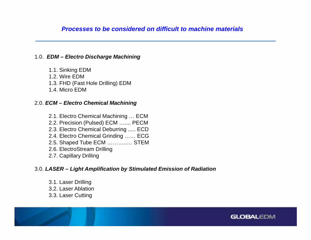
Processes to be considered on difficult to machine materials
1.0. EDM – Electro Discharge Machining
1.1. Sinking EDM1.2. Wire EDM1.3. FHD (Fast Hole Drilling) EDM1.4. Micro EDM
2.0. ECM – Electro Chemical Machining
2.1. Electro Chemical Machining … ECM2.2. Precision (Pulsed) ECM ….... PECM2.3. Electro Chemical Deburring ..... ECD2.4. Electro Chemical Grinding …… ECG2.5. Shaped Tube ECM ………..… STEM2.6. ElectroStream Drilling2.7. Capillary Drilling
3.0. LASER – Light Amplification by Stimulated Emission of Radiation
3.1. Laser Drilling3.2. Laser Ablation3.3. Laser Cutting

Processes to be discussed in this presentation
1.0. EDM – Electro Discharge Machining
1.1. Sinking EDM1.2. Wire EDM1.3. FHD (Fast Hole Drilling) EDM1.4. Micro EDM
2.0. ECM – Electro Chemical Machining
2.1. Electro Chemical Machining … ECM2.2. Precision (Pulsed) ECM …..... PECM2.3. Electro Chemical Deburring ..... ECD2.4. Electro Chemical Grinding …… ECG2.5. Shaped Tube ECM ………...… STEM2.6. ElectroStream Drilling2.7. Capillary Drilling
3.0. LASER – Light Amplification by Stimulated Emission of Radiation
3.1. Laser Drilling3.2. Laser Ablation3.3. Laser Cutting

Fast Hole Drilling EDM
FH40 FH50 FH60X, Y Axis 40”x20” (1000x500mm) 50”x25” (1250x635mm) 60”x30” (1500x750mm) Z Axis 26” (660mm) 24” (610mm) 24” (610mm)W Axis 26” (660mm) 26“ (660mm) 26” (660mm)
FHD-EDM Machines
• Multi-axis positioning and machining system
• Tilting head EDM Slide carries 600mm Electrodes
• Robot Tool Changer for untended production

Fast Hole Drilling EDM
X, Y Axis Travel 31.5” x 23.6” 800mm x 600mmZ Axis Travel 19.7” 500mmW Axis Travel 19.7” 500mm
FHD-EDM Machines

Fast Hole Drilling EDM

Fast Hole Drilling EDM
Tilting EDM Head has +/- 100* travel

Fast Hole Drilling EDM
Shown with large Turbine Bucket being drilled

Fast Hole Drilling EDM
Process principles
• EDM, using Deionized water as a dielectric
• Tubular Electrodes - both hollow and Multi-core –with dielectric flushed through – Copper or Brass
• High Depth to Diameter ratios possible because of theDielectric through-flushing
• A Thermal process, so Recast layer and Heat-affectedzone result
• Machines any conductive material, regardless of hardness or machinability

Fast Hole Drilling EDM
Applications
Aircraft Engine Combustion Liners
• Material ……….... Hastalloy X
• Ca 2,500 holes
• Holes …............ 0.025” - 0.046” (0.64 - 1.20mm)
• Wall thickness … 0.060” - 0.080” (1.50 - 2.0mm)
• Total time ………. 8.00 hours
• Time per hole ….. < 12 seconds
• Finish …………… < 250 u” (6.3um) Ra
• Tolerance, diameter … 0.004”(0.13mm)
• Tolerance, TP ……….. 0.020”(0.5mm)
• Number of Toolchanges ………… 68
Note curved Electrode Guide for access

Fast Hole Drilling EDM
Applications
Industrial Gas Turbine Dome Ring
• Material ……….... Hastalloy X
• Ca 4,250 holes @ angles so 0.33” (7.62mm)dp
• Holes …....... 0.050” - 0.070” (1.30 – 1.80mm)
• Wall ……...... 0.120” – 0.200” (3.00 -5.00mm)
• Total time ………. 40.00 hours
• Time per hole ….. < 34 seconds
• Finish …………… < 250 u” (6.3um) Ra
• Tolerance, diameter … 0.006”(0.15mm)
• Tolerance, TP ……….. 0.020”(0.5mm)
• Number of Toolchanges ………… 569

Creating a Shaped Hole by Interpolating the Brass Electrode during the EDM process. The Fanuc Control will Track Voltage to Simulate
Servo and Gap functions.
Creating a Shaped Hole by Interpolating the Brass Electrode during the EDM process. The Fanuc Control will Track Voltage to Simulate
Servo and Gap functions.
Fast Hole Drilling EDM
Shaped Hole Technology

Fast Hole Drilling EDM
Shaped Hole Technology

Shaped Hole Technology
Fast Hole Drilling EDM

Fast Hole Drilling EDM
For Videos on Fast Hole Drilling go to:
https://www.youtube.com/watch?v=Wz2lXpfBpd8
https://www.youtube.com/watch?v=EunVelGAKQE
https://www.youtube.com/watch?v=BB6mAlVexGg
https://www.youtube.com/watch?v=2iaTlCIZijo

ECM
Process principles
• Think of it as “Accelerated Reverse Electro Plating”
• Material is removed “Molecule-by-molecule”
• Stress-free surfaces produced
• Not a thermal process, so no Recastlayer or Heat-affected zone
• Significant forces as Electrolyte flows up to 300psi/300gpm (20bar @ 1,200l/m)
• Material Removal > 1.00 Cubic Inch per minute per 10,000 amps

ECM
ECM is used in machining applications, including:
• Automotive - nozzles, drilling, deburring, production of cavities and curved channels
• Aerospace – airfoils, BLISKS, casings and ong cooling channels in vanes
• Industrial Gas Turbines – buckets, fuel nozzles
• Domestic Appliances – electric razor foils
• BPE/Semiconductor Fittings
• Micro parts - microscopes and other measuring equipment, molds, fuel cell tooling
• Medical - implants and medical devices
• Textile Industry
• Optical Industry - lenses and micro drillings
• Printing Industry - micro and macro textures on large upper surfaces
ECM
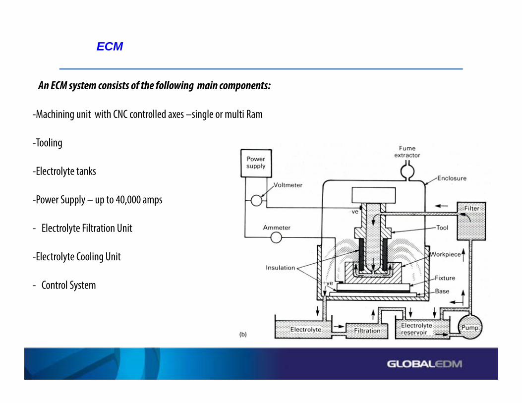
An ECM system consists of the following main components:
-Machining unit with CNC controlled axes –single or multi Ram
-Tooling
-Electrolyte tanks
-Power Supply – up to 40,000 amps
- Electrolyte Filtration Unit
-Electrolyte Cooling Unit
- Control System

Applications
ECM______________________________________________________________

ECM
Tooling
- Cathodes made of copper or stainless steel >>>>>
- Workpiece holding fixture
- Flow box to control the electrolyte flow

Applications
Medical Implants
ECM______________________________________________________________
<<<<< Cathode shown for Knee Implant
Hip Implant

Applications
• Diaphragm Valve Body
• Replaces long and tedious hand-finishing
• Repeatable fine surfaces producedin rapid time-cycles with multi-cavity Tooling
• eplaces CNC
ECM______________________________________________________________

ECM
Applications
• These 6.000” (150mm) diameter Titanium discs are ECM’ed to a stress-free condition with extremely thin wall thickness
• Result is a close-tolerance part with no distortion

ECM
Applications
• Tube Fittings has been ECM’ed after welding or bending to remove the excess weld material and to polish the internal surfaces.
• This can be done extremely rapidly with accuratetolerance and high repeatability on BPE and Semi Conductor Fittings
Applications
Applications

ECM
• Medium - conducting electrolyte, generally a Saline solution of Sodium Nitrate or Sodium Chloride
• Mechanics of material removal – electrolysis
• Tool material - Copper, brass, steel
• Tool life - infinite
• Machining gap 10 to 100 μm (0.0004” – 0.004”)
• Materials application - all conducting metals and alloys
• Critical parameters - voltage, current, feed rate, electrolyte conductivity
• Surface finishes down to 0.1 μm (4 MicroInch) Ra
• Shapes application - blind complex cavities, curved surfaces, through cutting, large through cavities
• Material Removal > 1.00 Cubic Inch per minute per 10,000 amps
Summary of ECM Characteristics

ECM
Various machine types

PECM
PECM :
• Pulsed (or “Precision” ECM)
• Oscillating Z Axis and Pulsed Power Supply
• Enables closer gaps
• Still uses Saline solution
• Gives much better Surface Finish than traditional ECM
• Enables much finer detail to be produced
• Capable of ECM’ing Tungsten Carbide

PECM
New Trends and Capabilities – using PECM

STEM Drilling
Introduction
• An ECM process that enables holes to be “drilled” to extreme L/D Ratios
• Specialized Applications such as Turbine“Buckets” and Extrusion Dies for Catalytic Converter material

STEM Drilling
Typical STEM Drilling Setup
Machine Features and Options:
• Daylight
• Stroke
• Number of Parts to be drilled
• Absolute encoders
• Positive air to Z axis
• Stainless Steel hardware
• Composite Granite base

STEM Drilling
Process principles
• ECM with Acid as an Electrolyte
• Nitric or sulphuric Acids used Ca 25% concentration
• Single axis process (Z) where Insulated Tubes descend into the part to be drilled
• Not a thermal process, so no Recast layer or Heat-affected zone
• Tubes advance at Ca 0.080” (2.00mm) per minute, regardless of quantity of holes
• Tubes are Titanium with special insulation (ParaXylene) on Outside Diameter
• Tubes have angled front-ends and need periodic Dressing
• All ECM action occurs on the exposed end of the Tube(s)
• STEM – “Shaped Tube Electrolytic Machining” – although mostly ROUND Holes!!

STEM Drilling
• Bi-Polar
• Forward Volts Machining - typically 15V for 5 seconds
• Reverse Volts to remove build-up of deposits on tip of tubes - typically 5V for 0.1s
• Sufficient Power to machine 3 blades simultaneously
• High Speed switch -off
• Water cooled
• Positive air pressure
Power Supplies

STEM Drilling
• Manufactured to ISO/CE Standards
• Timed Door interlocks – to allow fumes to be extracted
• Extraction of Hydrogen and acid fumes min 50m3/hour per 1000A
• Auto wash down of parts - valve directs water to separate tank
• Machine & Acid system connected to “Scrubber”
• PPE, including goggles, hats, aprons, gloves
• Stamp/handle drench shower
• Eye wash station
Safety features

STEM Drilling
• Acid must be a stable parameter
• Programmable emptying of dirty acid
• Programmable replenish of clean acid
• Remote control of wash down – with water
• Spreadsheet for Acid calculations
Acid management

STEM Drilling
Machine Radial Cooling Holes in Industrial Gas Turbine Buckets, including the following:
• Siemens 94.2
• GE Frame 6 - Row 1
• GE Frame 6 - Row 2
• GE Frame 7 - Row 1
• GE Frame 9 - Row 1

STEM Drilling
Cooling Holes produced up to 24” (600mm) deep
“Turbulated” holes for greater cooling efficiency

STEM Drilling
Typical Tooling includes
• STEM Tube Manifold
• STEM Tube Guide
• STEM Tube Target Plate
• Airfoil 6 point nest
• Clamping system

STEM Drilling
STEM Tube Manifold
• Provides through-flushing of Acid
• Variable flow
• Multiple tube sizes
STEM Drilling
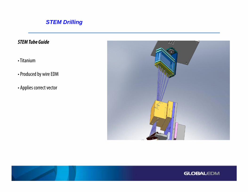
STEM Tube Guide
• Titanium
• Produced by wire EDM
• Applies correct vector

STEM Drilling
STEM Tube Target Plate
• Ensures alignment prior to machining
• Separate for root & tip machining
• Alignment is crucial to maintaining True Position
• True Position necessary to maintain“Minimum Wall” condition
• If “Minimum Wall” is not maintained then likelihood of Bucket burning-up in service!!

STEM Drilling
Airfoil Fixture
• Airfoil (6) point “nest” - to establish Stacking Axis of Bucket
• Clamping system
• Single or Multi Blade Fixtures

Processes discussed
1.0. EDM – Electro Discharge Machining
1.1. Sinking EDM1.2. Wire EDM1.3. FHD (Fast Hole Drilling) EDM1.4. Micro EDM
2.0. ECM – Electro Chemical Machining
2.1. Electro Chemical Machining … ECM2.2. Precision (Pulsed) ECM …..... PECM2.3. Electro Chemical Deburring ..... ECD2.4. Electro Chemical Grinding …… ECG2.5. Shaped Tube ECM ………...… STEM2.6. ElectroStream Drilling2.7. Capillary Drilling
3.0. LASER – Light Amplification by Stimulated Emission of Radiation
3.1. Laser Drilling3.2. Laser Ablation3.3. Laser Cutting
Thank you for your attention
Be sure to visit us in the show at Booth E-5033
John Stackhouse - Executive Vice PresidentGlobal Specialty Machines, Mason Ohio, USA
www.gedms.com
IMTS-2016