hot water temperature maintenance installation …€¦ · refer to the “hsx cable testing...
TRANSCRIPT

WarmTraceTM HSX™Hot Water Temperature Maintenance
INSTALLATION PROCEDURES

2
WarmTraceTM HSX
Familiarize yourself with the entire guide prior to installing any heating cable or components. Throughout this guide, the following symbols will appear to emphasize key points or an installation tip:
Safety Comes First. . .The safety and performance of a heat tracing system depends on how the system was designed, installed and eventually maintained. Improper handling, installation or maintenance of the system could result in underheating or overheating of the water or damage to the heating cable. This damage could result in electrical shock, fire or system failure. The information, in-structions, testing procedures and warnings addressed in this guide are important. To minimize these risks, read this guide prior to starting any heating cable or component installation and follow the instructions carefully.
Approvals/Code Compliances. . .Thermon's WarmTrace systems comprised of HSX heating cable and accessories are approved for hot water temperature maintenance by:
This symbol is intended to alert the user to the pres-ence of important installation, operation or mainte-nance instruction within the guide.
This symbol identifies an installation, operation or start-up tip that could save time, installation materi-als or make for an improved system.
CAUTION
Tools Required . . .
TIP
WarmTrace systems comply with the applicable requirements of the following code agencies:
• NEC, CEC• Uniform Plumbing Code• BOCA• Southern Building Code Congress• National Standard Plumbing Code
Be sure the electrical power connections comply with the National Electrical Code (NEC) Article 427 and any other ap-plicable national, state or local codes.
WarmTrace systems also meet or exceed the requirements of the IEEE Recommended Practice for Testing, Design, Installa-tion and Maintenance of Electrical Resistance Heat Tracing for Commercial Applications, ANSI/IEEE Standard 515.1
3
INSTALLATION PROCEDURES
Cable Type (Catalog No.) Outer Jacket Color Voltage (Vac)
HSX 2105-2 Blue 208
HSX 2120-2 Green 208
HSX 2140-2 Red 208
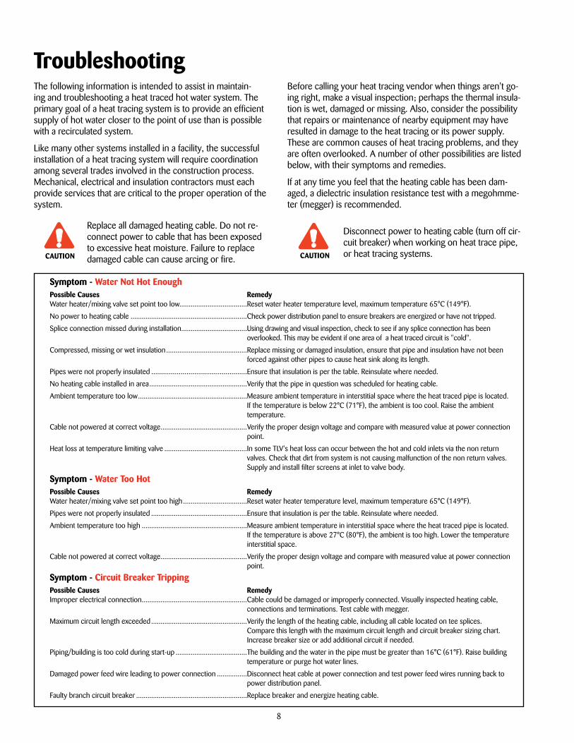
Typical Heat Tracing Installation. . .A complete electric heat tracing system will typically include the following components:
1. HSX self-regulating heating cable.
2. PowerSnap1 or PCA-COM power connection kit to terminate heating cable.
3. TeeSnap or PCS-COM allows three heating cables to be spliced together.
4. SpliceSnap or PCS-COM allows two heating cables to be spliced together.
5. ET-6 cable end termination. Each PowerSnap1 and TeeSnap includes two ET-6 terminations.
6. FT-1 Attachment tape secures cable to pipe; use on 300 mm (12") intervals.
7. CL "Electric Heat Tracing" label peel and stick to insulation vapor barrier on a 3m (10') interval or as require by code or specification.
8. Fiberglass thermal insulation and vapor barrier.
The National Electric Code and Canadian Electrical Code require ground fault protection be provided for all electric heat tracing.
CAUTION
1
2
8
7
3
6
5
4
Refer to the “HSX Cable Testing Report” for required recording of test data and circuit information.
Receiving, Storing, Handling . . .1. Upon receiving heating cable, check to make sure the
proper type and output have been received. All cables are printed on the outer jacket with part number, voltage rating and watt output.
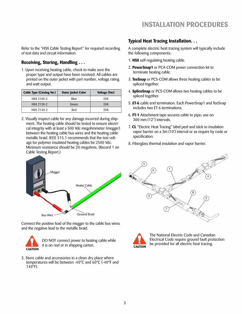
DO NOT connect power to heating cable while it is on reel or in shipping carton.
Bus Wire Ground Braid
Heater Cable
Megger
2. Visually inspect cable for any damage incurred during ship-ment. The heating cable should be tested to ensure electri-cal integrity with at least a 500 Vdc megohmmeter (megger) between the heating cable bus wires and the heating cable metallic braid. IEEE 515.1 recommends that the test volt-age for polymer insulated heating cables be 2500 Vdc. Minimum resistance should be 20 megohms. (Record 1 on Cable Testing Report.)
Connect the positive lead of the megger to the cable bus wires and the negative lead to the metallic braid.
3. Store cable and accessories in a clean dry place where temperatures will be between -40°C and 60°C (-40°F and 140°F).
CAUTION

4
WarmTraceTM HSXPrior to Installing Cable. . .1. Verify Electrical Resistance with a megger.
• Refer to Cable Testing Section in this Installation Guide for details.
2. Inspect the piping to be heat traced.
• Verify that the pipe has been pressure tested, and that all pipe supports are in place.
• Compare layout of the installed piping vs plumbing drawings.
3. Surface areas where heat tracing is to be installed must be reasonably clean. Remove dirt, rust and scale with a wire brush and oil or grease films with a suitable solvent.
4. Plan the installation.
• Some of the hot water supply may not require heating cable. Note the extent of heat tracing required by reviewing:
1. Project specification
2. Plumbing drawings
3. Drawings supplied by Thermon (If a drawing package was part of heat trace system).
• Allow sufficient cable to cover the longest runs first. This will insure that no additional cable or splice kits will be required.
• The extent of heat tracing, location of power connection points, splice and end terminations can be temporarily identified with marking ribbon or spray paint.
5. Identify the heat tracing materials.
• The cable should have been identified upon receipt. Be sure to make note that more than one water maintain temperature, and therefore more than one HSX cable, may be required for the project.
• Familiarize yourself with the connection kits and accessory components included with the bill of materials.
Power Connection Points: The power (electrical) connec-tion points must remain accessible, even after the building is completed. If the facility will be finished out with a suspended ceiling, power connection points can be located anywhere that is convenient and accessible to electrical power. If the finished ceiling is permanent, each power connection point should be located within reach from the access door.
Tee Splice Connections and End Terminations: Thermon rec-ommends that wherever possible, all connections and termi-nations be located in an area that allows future access should changes or additions to the plumbing system be needed.
Initial Installation. . .Begin temporary installation at the proposed end-of- circuit location and lay out heating circuit on pipe, allowing extra cable for the power connection and for any splice locations.
Locating Power, Tee and End Termination: Refer to the plumbing, electrical or Thermon supplied drawings to deter-mine the locations for connections and terminations. The sym-bols below are routinely used to show the various components of a heat trace hot water supply system. Note that the electrical drawings will typically only show the power connection point.
Circuit Continued on Another Sheet
Electrically Heat-Traced Hot Water Line
Heating Cable T-Splice Kit
End-of-Circuit Termination
Power Connection Point

5
INSTALLATION PROCEDURES
Attachment Tape (Value Represents Approximate Linear Pipe Length Allowance Per Roll)
Where space is a problem, Thermon approved plastic cable ties may be used on the same interval as tape. Do not over tighten cable ties.
NO NOT attach cable to pipe with metal hose clamps, metal strapping, tie wire or similar materials. Damaged to cable and system could result.
Avoid pinch points when installing cable. Over the course of time, the pipe will move due to vibration, thermal expansion, contraction and building settling. Do not allow the heating cable to bind between items such as pipe supports, wall or floor penetrations.
Pipe supports: Run the heating cable on the outside of any pipe hanger or support that comes in contact with the pipe. Thermon recommends the use of insulated pipe supports to prevent additional heat loss at the point of support.
TapeLength
Pipe Diameter in Inches
½"-1" 1¼" 1½" 2" 3" 4" 6"
33 m(36 yd)
39 m(130')
35 m(115')
23 m(110')
29 m(95')
23 m(75')
20 m(65')
15 m(50')
55 m(60 yd)
65 m(215')
59 m(195')
55 m(180')
49 m(160')
38 m(125')
32m(105')
24 m(80')
Installing Cable on Pipe. . .1. Placement Of Cable
The HSX cable will be installed on the pipe in a parallel pass. There is no need for spiral wrapping. Locate the cable in the 10 or 2 o'clock position where possible. If accessibility is a problem the cable may be installed in the 4 or 8 o'clock position.
Insulated Pipe Support: For cork or polyurethane insulation insert, cut small hole for cable to pass through.
10 O'clock 2 O'clock
4 O'clock8 O'clock
Hot Water Pipe
Heater Cable
FT-1L Tape
2. Attaching Cable to the Pipe
The HSX is held in place with temperature-rated attach-ment tape (FT-1L). Circumferential bands of tape should be installed at 300mm (12") intervals to ensure the cable main-tains proper contact with the pipe.
305mm
(12")
CAUTION
TIP
Do Not Install Cable Like This:Install Cable Like This:
Pipe Support
Cutout for CableInsulation Insert

6
WarmTraceTM HSX
Maximum Circuit Length vs. Circuit Breaker Size
Maximum Circuit Lengths. . .To prevent excessive electrical currents at the branch circuit breaker supplying power to the heating cable, the maximum circuit length as shown in the chart below must be observed.
Notes:
1. These maximum circuit lengths are defined as the total length of cable that can be fed from a single power connection point, inclusive of all splices.
2. Be sure to verify the available amperage of the branch circuit breaker sup-plying power to the heat tracing.
3. If the power supply voltage will be different than that listed in the chart above, contact Thermon or your local Thermon representative before install-ing any cable.
4. Any number of shorter heat tracing circuits can be energized from a single branch circuit breaker as long as the total length of heating cable does not exceed the length stated above for a given branch circuit breaker's amper-age rating.
Completing the Installation. . .1. Begin final cable attachment by securing the end-of-circuit
termination kit and working back toward the power supply.
• Circumferential bands of tape should be installed at 300 mm (12") intervals to keep the cable in proper con-tact with pipe.
• If applicable, refer to installation details provided with the project drawings or contract Thermon for additional infor-mation regarding installation.
2. Complete splice connections (if required) in accordance with the installation instructions provided with the splice kit.
3. Install power connection kit in accordance to detailed instal-lation instructions provided with the kit.
4. Before making power connections, repeat the megger test with at least a 500 Vdc megohmmeter (megger) between the heating cable bus wire and heating cable metallic braid. IEE 515.1 recommends that the test voltage for polymer in-sulated heating cable be at 2500 Vdc. The minimum accept-able level for the megger reading for any polymer insulated heat tracing cable is 20 megohms. (Record 2 on Cable Test-ing Report)
Wall or Floor Penetrations: The heating cable must be pro-tected when passing between floors or through a wall. This can be accomplished with pieces of conduit or channel. If penetra-tion requires fire protection, the conduit or channel may be caulked with approved caulking material.
Catalog No. Voltage Breaker Size 15 Amp 20 Amp 30 Amp
HSX 2105-2(Blue) 208331 m(1085')
366 m(1200')
366 m(1200')
HSX-2120-2 (Green) 208146 m(480')
195 m(640')
293 m(960')
HSX-2140-2 (Red) 20884 m(275')
113 m(370')
169 m(555')
Floor or Wall
Hot Water Pipe
Channel
Heater Cable

7
INSTALLATION PROCEDURES
Final Inspection and Documentation . . .1. It is recommended that the circuit be temporarily energized
so that the volts, amps, pipe temperature and ambient temperature may be recorded. This information may be of value for future reference and should be maintained for the historical operating data log (Record 4 on Cable Testing Report).
2. Once power is connected but before putting the system into operation, verify all heating cable testing and documen-tation have been completed for each heat tracing circuit. This will ensure that the system has been installed per the manufacturers recommendations.
Thermal Insulation with Weather Barrier
Heating Cable (Typical)
Weather BarrierThermal Insulation
Record the location of all terminations on plumbing drawings after each termination has been completed. This will ensure that no terminations are overlooked and will document the extent of the heat tracing on the drawing.
Thermal Insulation . . .1. The need for properly installed and well-maintained thermal
insulation cannot be overemphasized. Without insulation, heat losses are generally too high to be offset by a conven-tional heat tracing system.
2. Regardless of the type or thickness of insulation used, a protective barrier should be installed. This protects the in-sulation from moisture intrusion, physical damage and helps ensure the proper performance of the heat tracing system. Seal around all penetrations through the thermal insulation.
3. After the installation of the thermal insulation and weather barrier but BEFORE ENERGIZING THE HEATING CIRCUIT, the megohmmeter test should be repeated. This should call attention to any damage to the heating cable that may have occurred during the insulation installation. (Record 3 on Cable Testing Report)
4. Apply caution labels to insulation weather barrier at required intervals along pipe
Start-Up Procedure . . .When a WarmTrace system has been installed per this guide, start-up is easy. Simply follow the steps listed below. Please note that the operating current for the cable will be higher during start-up than during normal operating conditions. This is because the water in the heat trace piping is usually at the building ambient temperature. This condition has been ac-counted for in the breaker sizing and current length table pro-vided so long as the ambient temperature is at or above 15˚C (60˚F).
1. On closed loop systems a valve or faucet should be partially opened to prevent excessive pressure accumulation as tem-peratures rise.
2. Energize the heating cable and allow the system to reach its equilibrium temperature. The building water heater should be operating and the building's environment should be at ambi-ent temperature 22˚C-27˚C (72˚F-80˚F).
3. The water heater/mixing valve which controls the water supply temperature should be set at the same temperature as the heating cable's nominal value i.e. 45˚C (105˚F), 49˚C (120˚F) or 60˚C (140˚F) Variations greater than ±5°C (10˚F) could cause noticeable swings during operation.
4. Using a calibrated thermometer, check the water tempera-ture at the water heater to be certain that it is within the desired range.
5. Again, using a calibrated thermometer, check the water temperature at various tap locations that are heat traced. Al-low sufficient time for water to pass any unheated portion of water line.
6. Test for ground-fault protection by manually tripping the push-to-test button on the device (remember to reset after the test).
If start-up is not successful, refer to the Trouble Shooting sec-tion of this guide for assistance.
Disconnect power to heating cable (turn off circuit breakers) during water heater start-up and hot water system purging if water temperature will exceed 65˚C (150˚F).CAUTION
TIP
TroubleshootingThe following information is intended to assist in maintain-ing and troubleshooting a heat traced hot water system. The primary goal of a heat tracing system is to provide an efficient supply of hot water closer to the point of use than is possible with a recirculated system.
Like many other systems installed in a facility, the successful installation of a heat tracing system will require coordination among several trades involved in the construction process. Mechanical, electrical and insulation contractors must each provide services that are critical to the proper operation of the system.
Replace all damaged heating cable. Do not re-connect power to cable that has been exposed to excessive heat moisture. Failure to replace damaged cable can cause arcing or fire.
Disconnect power to heating cable (turn off cir-cuit breaker) when working on heat trace pipe, or heat tracing systems.CAUTION
Symptom - Water Not Hot EnoughPossible Causes RemedyWater heater/mixing valve set point too low. ...................................Reset water heater temperature level, maximum temperature 65°C (149°F).
No power to heating cable ..............................................................Check power distribution panel to ensure breakers are energized or have not tripped.
Splice connection missed during installation ...................................Using drawing and visual inspection, check to see if any splice connection has been overlooked. This may be evident if one area of a heat traced circuit is "cold".
Compressed, missing or wet insulation ...........................................Replace missing or damaged insulation, ensure that pipe and insulation have not been forced against other pipes to cause heat sink along its length.
Pipes were not properly insulated .................................................Ensure that insulation is per the table. Reinsulate where needed.
No heating cable installed in area ....................................................Verify that the pipe in question was scheduled for heating cable.
Ambient temperature too low ..........................................................Measure ambient temperature in interstitial space where the heat traced pipe is located. If the temperature is below 22°C (71°F), the ambient is too cool. Raise the ambient temperature.
Cable not powered at correct voltage ..............................................Verify the proper design voltage and compare with measured value at power connection point.
Heat loss at temperature limiting valve ............................................In some TLV's heat loss can occur between the hot and cold inlets via the non return valves. Check that dirt from system is not causing malfunction of the non return valves. Supply and install filter screens at inlet to valve body.
Symptom - Water Too HotPossible Causes RemedyWater heater/mixing valve set point too high ..................................Reset water heater temperature level, maximum temperature 65°C (149°F).
Pipes were not properly insulated ...................................................Ensure that insulation is per the table. Reinsulate where needed.
Ambient temperature too high ........................................................Measure ambient temperature in interstitial space where the heat traced pipe is located. If the temperature is above 27°C (80°F), the ambient is too high. Lower the temperature interstitial space.
Cable not powered at correct voltage ..............................................Verify the proper design voltage and compare with measured value at power connection point.
Symptom - Circuit Breaker TrippingPossible Causes RemedyImproper electrical connection ........................................................Cable could be damaged or improperly connected. Visually inspected heating cable,
connections and terminations. Test cable with megger.
Maximum circuit length exceeded ...................................................Verify the length of the heating cable, including all cable located on tee splices. Compare this length with the maximum circuit length and circuit breaker sizing chart. Increase breaker size or add additional circuit if needed.
Piping/building is too cold during start-up ......................................The building and the water in the pipe must be greater than 16°C (61°F). Raise building temperature or purge hot water lines.
Damaged power feed wire leading to power connection ................Disconnect heat cable at power connection and test power feed wires running back to power distribution panel.
Faulty branch circuit breaker ...........................................................Replace breaker and energize heating cable.
CAUTION
Before calling your heat tracing vendor when things aren't go-ing right, make a visual inspection; perhaps the thermal insula-tion is wet, damaged or missing. Also, consider the possibility that repairs or maintenance of nearby equipment may have resulted in damage to the heat tracing or its power supply. These are common causes of heat tracing problems, and they are often overlooked. A number of other possibilities are listed below, with their symptoms and remedies.
If at any time you feel that the heating cable has been dam-aged, a dielectric insulation resistance test with a megohmme-ter (megger) is recommended.
8

9
INSTALLATION PROCEDURES
Maintenance Check List. . .As part of an annual maintenance program or after any work (repair or alteration) has been performed on or near the heat traced piping, the following steps should be performed:
1. Visually inspect the pipe's thermal insulation looking for any areas where the insulation appears repaired or replaced. Any suspect areas should be examined for damage to the heating cable. Verify that any new/repaired insulation meets the specification.
2. While inspecting the insulation, verify that it is completely dry. Wet insulation will not only cause temperature mainte-nance problems, but could also signal a more serious prob-lem that could cause damage to the cable and the facility.
3. Test for ground-fault protection by manually tripping the push-to-test button on the device (remember to reset after the test).
4. Using a calibrated thermometer, check the water tempera-ture at the water heater to be certain that it is within the desired range.
5. Again, using a calibrated thermometer, check the water temperature at various tap locations that are heat traced. Al-low sufficient time for water to pass any unheated portion of water line.
6. Heating cable should tested with a megohmmeter (megger) at the power distribution panel by a qualified electrician.
7. Record any observations on the project's as-built drawings and any maintenance log kept for facility.
Do Not enter any power connection point, ca-ble splice or end termination while heating cable is energized. Disconnect power to heating cable and seek qualified assistance.CAUTION

1. Refer to Thermon Installation Procedures, FORM CPD 1014, for general installation procedures, requirements and guidelines.
2. Upon receiving heating cable, check the cable to make sure the proper type and output have been received. All flexible cables have the catalog number, voltage rating and watt output printed on the outer jacket.
3. Visually inspect cable for any damage incurred during shipment. The heating cable should be tested to ensure electrical integrity with at least a 500 Vdc megohmmeter (megger) between the heat-ing cable bus wires and the heating cable metallic braid. IEEE 515.1 recommends that the test voltage for polymer insu-lated heating cables be 2500 Vdc. Minimum resistance should be 20 megohms. (Record 1 on Cable Testing Report.)
A. Connect the positive lead of the megger to the cable bus wires.
B. Connect the negative lead of the megger to the metallic braid.
C. Energize the megger and record the reading. Readings between 20 megohms and infinity are acceptable. Readings below 20 megohms may mean the electrical insulation has been dam-aged. Recheck the heating cable for physical damage between the braid and the heating element; small cuts or scuffmarks on the outer jacket will not affect the megger reading unless there was actual penetration through the braid and dielectric insulation jacket.
4. Once the installation is complete, but prior to installation of thermal insulation, recheck the heating cable with at least a 500 Vdc megohmmeter (megger) between the heating cable bus wires and the heating cable metallic braid. IEEE 515.1 recommends that the test voltage for polymer insulated heating cables be 2500 Vdc. Minimum resistance should be 20 megohms. (Record 2 on Cable Testing Report.)
5. After the thermal insulation is installed, the megohmmeter test should be repeated. Minimum resistance should be 20 megohms. (Record 3 on Cable Testing Report.)
6. After the thermal insulation is installed and power supply is completed, record the panel and circuit breaker information. Ensure all junction boxes, temperature controllers, cable glands, etc. are properly secured. Apply rated voltage to the heat tracing circuit(s) for 10 minutes. Record the ambient temperature, measure and record the circuit(s) voltage and current. (Record 4 on Cable Testing Report.)
NOTE: To ensure the heating cable warranty is maintained through installation, the testing outlined on this sheet must be completed on the installed heating cables, and the test results recorded and mailed/faxed to:
Thermon Customer Service 100 Thermon Drive San Marcos, Texas 78666 Fax: 512-754-2420
9
WarmTraceTM HSX Cable Testing Report

Customer: Contractor:
Address: Address:
Phone No: Phone No.
Project Reference:
Record 1: Prior to Installation Cable Type:
Heater Length:
Heater Number:
Insulation Resistance M Ohms:
Tested By: Date:
Witnessed By: Date:
Record 2: After Installation Insulation Resistance M Ohms:
Tested By: Date:
Witnessed By: Date:
Record 3: After Thermal Insulation is Installed Insulation Resistance M Ohms:
Tested By: Date:
Witnessed By: Date:
Record 4: Final Commissioning Panel Number:
Breaker Number:
Volts:
Ambient Temperature (deg. F):
Recorded Amps:
Tested By: Date:
Witnessed By: Date:
10
WarmTraceTM HSX Cable Testing Report

Form
CPD
1014
-100
8
THERMON . . . The Heat Tracing Specialists®
100 Thermon Dr. • PO Box 609 • San Marcos, TX 78667-0609Phone: 512-396-5801 • Facsimile: 512-396-3627 • 1-800-820-HEATwww.thermon.com In Canada call 1-800-563-8461