hot stitch” control - nordsonemanuals.nordson.com/adhesives/english_manuals/104494.pdf ·...
TRANSCRIPT

Hot Stitch” Control Model CST-1
Part 104 494A
NORDSON CORPORATION. AMHERST, OHIO. USA

Nordson Corporation welcomes requests for information, comments and inquiries about its products.
Address all correspondence to
Nordson Corporation 11475 Lakefield Drive
Duluth, GA 30136
Notice
This is a Nordson Corporation publication which is protected by copyright. No part of this document may be photocopied, reproduced, or translated to another language without the prior written consent of Nordson
Corporation. The information contained in this publication is subject to change without notice.
Trademarks
AquaGuard, Blue Box, Control Coat, Equi=Bead, FloMelt, FoamMelt, FoamMix, Helix, Hot Shot, Hot Stitch, Meltex, MicroSet, MultiScan, Nordson, the Nordson logo, OmniScan, Porous Coat, Posi-Stop, RBX, Sure-Bond,
UniScan, UpTime, and Versa-Spray are registered trademarks of Nordson Corporation.
BetterBooksM, CF, Controlled Fiberization, Easy-Screen, Fibermelt, Flo-Tracker, PrintGuard, and Package of Values are trademarks of Nordson Corporation.
Manual 57-12 104 494A Issued 1 O/83
0 1983 Nordson Corporation All Rights Reserved

Section
0 Nordson Packaging and Assembly Division Atlanta, Georgia TECHNICAL PUBLICATION 57-12-01
TABLE OF CONTENTS
I
II
III
IV
V
VI
LIST OF ILLUSTRATIONS. . . o . . . . . . . 57-12-02
LIST OF TABLES . . . . . . 4, e . . o . . o 57012003/04
SAFETYSUMMARY. o . . . . (, . . . . . e.
EQUIPMENT FAMILIARIZATION. 4, . . . . . o . 57-12-l Functional Description.+ . . . . e . . 57-12-l Feature Variations and Options. . . . 57-12-2 Specifications. . . . m . o . a e . . 57-12-2
PREPARATION FOR USE. . . . m . . . . . Q . Introduction. . . . . .' . . . . . . . Unpacking . . . . . . ti . . . . . - . Inspection. . . . . . . . . . . . . Physical Installation : . . . . . . . Electrical Installatioh . . . . . . o Trigger Installation. . . o e . = . Gun Installation. . . 1 . . e . . o .
OPERATING INSTRUCTIONS . Setup and Initial Operatioi ...........
Adjusting Bead Placement on the Case. .........
Daily Operation ...........
MAINTENANCE.. Introduction:
. . . . . . . . . . . . . . . . . . .
Preventive Mai%mance: . . . . . - . Corrective Maintenance, . . .
Mechanical Troubleshooting . . . Electrical Troubleshooting . . .
Disassembly and Repair, . . . . . o d
DIAGRAMS AND TABLESo . . . . . . . . . . . 57012-21/22
ILLUSTRATED PARTS LIST . . . . . . . . o . 57-12-29 Recommended Spare Parts . . . t . . . 57-12-32
Page
40-1-l
57-12-S 57-12-5 57-12-5 57-12-5 57-12-5 57-12-6 57-12-7 57-12-8
57-12-11 57-12-11
57-12-12 57-12-13/14
57-12-15 57-12-15 57-12-15 57-12-15 57-12-15 57-12-15 57-12-20
lSSlJE0 lo/83 LITHO U.S.A.
SUPERSEDES 0 NORDSON CORPORATION 1983 All Rights Reserved

57-12-02 0 Nordson Packaging and Assembly Division
Atlanta, Georgia TECHNICAL PUB1 /CA T/ON
LIST OF ILLUSTRATIONS
Figure No. Title
/SSllED lo/83 LITHO U.S.A.
Model CST-1 Hot Stitch Control. . .
CST-1 Dimensions. .........
Terminal Block Wiring .......
Typical Installation on Case Sealer
Programming Switches and Controls .
CST-1 Wiring Diagram. .......
Hot Stitch Control. ........
SUPERSEDES
.
.
Page
57-12-l
5791203/4
57-12-6
57-12-8
57-12-11
57012021/22
57-12-30
o NORDSON CORPORATION 1983 All Rights Reserved

0 Nordson Packaging and Assembly Division
Atlanta, Georgia TECHNICAL PUBLICATION 57012-03/04
LIST OF TABLES
Table No. Title Paqe
1 CST-1 Hot Stitch Control Minimum Stitch/Gap Lengths vs Conveyor Speed (Standard Units). . . . . l o . 57-12-23
2 CST-1 Hot Stitch Control Minimum Stitch/Gap Lengths vs Conveyor Speed (Metric Units). . . . . e . . e 57-12-25
3 Calculating CST-1 Dial Settings from Milliseconds . . . . . . . . . . 57-12-27/28
~~JED lo/83 bITHO U.S.A.
SUPERSEDES o NORDSON CORPORATION 1983 All Rights Reserved


0 Nordson PackagIng and Assembly Dwlsion
Atlanta, Georgia TECHNICAL PUB1 ICA TION 57-12-l
SECTION I EQUIPMENT FAMILIARIZATION
CST-1 HOT STITCH CONTROL
Q P
I!3 (0
-J 0
Figure 1 - Model CST-1 Hot Stitch Control
The Nordson CST-1 Hot Stitch Control is a solid state timing device for use with Nordson hot melt and cold glue applicator systems. It can be used in case and carton sealing operations or in various specialized applications where a stitch pattern of adhesive deposi- tion is desirable. When the adhesive stitches are properly spaced, they form a continuous bead upon compression, thus providing the holding power of continuously applied material, but with far less adhesive.
FUNCTIONAL DESCRIPTION
The Nordson CST-1 Hot Stitch Control is a timing device designed to operate in conjunction with Nordson adhesive application systems. Most commonly, it is used with Nordson automatic hot melt guns.
When the signal from a triggering device (limit switch) located on the conveyor line apparatus is received by the control, it initiates a series of signals to the hot melt gun solenoid. results in a stitch pattern of adhesive being applied to the
This
substrate. The length and placement of the stitches are determined by the preset durations of the signals; from the CST-1 to the gun solenoid. The stitch pattern conslists of a STITCH GROUP of uniform beads and gaps followed by a larger MAIN GAP. The CST-1 will cause this stitch pattern to be applied for as long as the limit switch triggering device is activated by the substrate.
ISSUED lo/83 LITHO U.S.A.
SUPERSEDES ( NORDSON CORPORATION 1983 All Rights Reserved

57-12-2 0 Nordson Packaging and Assembly Division
Atlanta, Georgia TECHNICAL PUB1 ICATION
Four controls on the front panel of the CST-1 cabinet determine the lengths of the individual stitches, stitch gaps, stitch group I and main gap. cabinet.
There are also two switches inside the The first switch allows the operator to choose from two
main gap interval ranges. The second switch determines whether the stitch group will be applied as a stitch group or as a solid bead between main gaps. These features permit greater flexibil- ity in the selection of adhesive application patterns.
FEATURE VARIATIONS AND OPTIONS
The CST-1 is available in either a 115 VAC version or a 230 VAC version.
SPECIFICATIONS
MODEL CST-1 HOT STITCH CONTROL
Dimensions See Figure 2
I +T2+ I Stitch Off
Stitch Group Time Interval (Tl) 40 - 840 Milliseconds
Main Gap Time Interval (T2) Range 1 Range 2
90 - 1,000 Milliseconds 800 - 1,700 Milliseconds
Stitch Length Interval (T3) 5- 100 Milliseconds
Stitch Gap Interval (T4) 5- 100 Milliseconds
Input Trigger Limit Switch
Electrical Input* 115 VAC (or 230 VAC), 50/60 Hz, 50 W
Electrical Output 115 VAC, 50/60 Hz, 0.4A
Operating Temperature Range 32 - 132'F (0 - 55'C)
*The CST-1 should not be field converted from one voltage to another.
ISSUED lo/83 LiTHO U.S.A.
SUPERSEDES ‘J NORDSON CORPORATtON 1983 All Rights Reserved

0 Mordson Packaging and Assembly Dlvwon
Atlanta, Georgia
I+ A-----+
L .
A. 8.0 in. (203.2 mm) B. 6.0 in. (152.4 mm) C. 11.5 in. (292.1 mm)
lSSUED lo/83 LITHO U.S.A.
TECHNICAL PUB1 /CATION 57-1203/4
I’ DC
D. 10.75 in. (273. E. 4.0 in. (101.6
-E-
Figure 2 - CST-1 Dimensions
SUPERSEDES (LJ NORDSON CORPORATION 1983 All Rights Reserved


0 Nordson Packaging and Assembly Division
Atlanta, Georgia TECHNICAL PUB1 ICATION 57-12-5
SECTION II PREPARATION FOR USE
INTRODUCTION
The following paragraphs describe procedures for unpacking, inspecting, and installing the CST-1 Hot Stitch Control.
UNPACKING
The CST-1 Hot Stitch Control is a one-piece unit contained within a single cabinet. Simply remove the unit from its packing. Store or dispose of packing materials promptly so as to minimize possible fire or mechanical hazards associated with having such materials in an industrial environment.
0 Handle the unit with care. Do not drop the unit or place it where it will be exposed to intense vibration, extreme heat, strong magnetic fields, or moisture.
INSPECTION
After unpacking the CST-1, inspect thle exterior and interior of the cabinet for signs of damage. nents.
Also chleck for loose wires or compo- Inspect fasteners for proper fit.
0 Be extremely careful not to damage any interior compo- nents during inspection.
Be certain that the electrical specifications on the CST-1 information plate (located on the side of the cabinet near the cabinet latches) agree with the requirements of the particular location where the unit will be used.
PHYSICAL INSTALLATION
1. The CST-1 should be mounted in a location free of intense vibration or extremes of temperature.
2. The unit may be mounted on the parent machine or on a separate stand. If the unit is subject to excessive vibration from the parent machine, it is recommended that vibration insulators (not supplied with unit) be used on the mounting, or that the unit be mounted separately near the parent machine.
3. If the unit is mounted independently, the cabinet should be located as close to the conveyor line as possible.
4. The unit should be mounted so that the controls are readily accessible and the door to the cabinet can be opened com- pletely.
ISSUED 1 O/8 3 LITHO U.S.A.
SUPERSEDES ‘LJ NORDSON CORPORATION 1983 All Rights Reserved

5742-6 0 Nordson Packaging and Assembly Division
Atlanta, Georgia TECHNICAL PUB1 /CATION
0 Do not install the CST-1 inside another enclosure, directly over the hot melt applicator, or in any other location where high temperatures may affect the unit's performance.
Do not install the unit where it will be exposed to excessive moisture, strong magnetic fields, large amounts of dust, other foreign matter, or corrosive substances.
ELECTRICAL INSTALLATION
A ‘s
A 5
The CST-1 Hot Stitch Control contains electrical poten- tials that are dangerous and can be fatal. Exercise extreme caution when installing, operating, and servicing this equipment. Only qualified personnel should install and service the CST-1.
To prevent electrical shock during installation and servicing, Nordson recommends installation of a lockout type circuit breaker or fused disconnect switch in the service line ahead of the control unit. This is manda- tory where required by local electrical codes. The CST-1 must also be connected to a reliable earth ground.
1. Loosen the screws on both retaining clips at the right side of the cabinet door. Slide these clips away from the door flange and open the door for access to the terminal block, TBl.
2. Connect the electrical input line (115 or 230 VAC, 50/60 Hz) to terminals 1 and 2 on the terminal block and connect the ground wire to terminal 3 (see Figure 3).
NOTE: The CST-1 must be grounded properly for the solenoid to function, as the solenoid% electrical circuit includes the connection to ground.
TBI
Figure 3 - Terminal Block Wiring
ISSUED lo/83 SUPERSEDES LITHO U.S.A.
1 NORDSON CORPORATION 1983 All Rights Reserved

0 Nordson Packaging and Assembly Division
Atlanta, Georgia TECHNICAL PUB1 ICATION 57-12-7
Terminal 3 on the terminal lblock should be solidly connected to the building and/or the packaging machine ground. Failure to ground the unit could cause personal injury in the event of an accidental short.
NOTE: Do not field convert the CST-1 from one voltage to another.
NOTE: The 230 VAC CST-1 must be used with non-grounded Ll and L2 power input leads only.
3. Connect the solenoid leads from the hot melt gun to terminals 8 and 9 on the terminal block (see Figure 3). A 115 VAC, 50/60 Hz solenoid is used with both the 115 VAC and 230 VAC models.
0 Do not short or jumper terminals 8 and 9. The AC solid state switch will fail under short circuit conditions.
4. Connect the leads from the %ommorP and "normally open" terminals on the limit switch to terminals 11 and 12 on the terminal block (see Figure 3).
NOTE:
5. When
Use shielded cable when connecting the to the triggering device. Ground the control unit only, using terminal 10. ground loop by grounding both ends of --
Hot Stitch unit cable at the Do not create a the cable. -
all electrical connections have been made, close the cabinet door and fasten it securely.
TRIGGER INSTALLATION
In general, the trigger mechanism must be securely mounted on the conveyor line apparatus and located as tion as possible.
close to the gun installa- However, it should not be located so that it
will be exposed to splashed adhesive from the gun.
Mount the limit switch (not supplied with the control unit) so that as the case/substrate passes beneath the hot melt gun it will close the switch and activate the timer (see Figure 4). Allow for some adjustment of the switch mounting to facili- tate more accurate bead positioning later on. Position of the switch in relation to the gun will dic:tate whether or not the hot melt beads are properly deposited,
ISSUED 1 O/8 3 LITHO U.S.A.
SUPERSEDES \I NORDSON CORPORATION 1983 All Rights Reserved

57-12-8 0 Nordson Packaging and Assembly Diviston Atlanta. Georgia TECHNICAL PUB1 ICATION
Figure 4 - Typical Installation on Case Sealer
A. Limit Switch B. Nordson Hot Melt Gun and Solenoid c. CST-1 Timer
Limit switches used as triggers should be wired in the normally open (N.O.) position and connected to the cabinet with a shielded cable (see 57-O-7, Appendix). The shield must be grounded at the control cabinet only, not at the switch. Connections should be made as shown in Figure 3.
NOTE: NEVER run the input power signal wires, and the gun a common conduit.
leads, the triggering device solenoid electrical leads in
The electrical input leads should be isolated from the triggering device signal wires. The triggering device electrical leads should be isolated from the power input leads and solenoid leads.
GUN INSTALLATION
The hot melt applicator gun must be mounted securely on the con- veyor line apparatus near the triggering device but not near enough to splash adhesive on it.
In applications using pneumatically actuated guns, the solenoid valve should be located as close to the gun as possible to mini- mize the mechanical delay inherent in the activation and deacti- vation of the gun. Air pressure to the solenoid should be in the
ISSUED lo/83 LITHO U.S.A.
SUPERSEDES ’ 1 NORDSON CORPORATION 1983 Ail Rights Reserved

0 Nordson Packaging and Assembly Dwlsion
Atlanta, Georgia TECHNICAL PUB1 ICATION 57-12-g/10
50-70 psig range (340 - 480 kPa), and the air supply line and fit- tings must be free of leaks and/or restrictions that would affect the system's mechanical efficiency.
Route the gun solenoid cable from the solenoid to the CST-1 cabinet. When the cable has been routed and fastened in place, cut the cable to length, and attach the stripped ends to the solenoid leads and the Hot Stitch terminal board (see Figure 3).
0 All cables should be routed so that they are well away from vehicular and pedestrian traffic, moving mechanical parts, and areas with high temperature or excessive moisture. Once routed, they should be held in place with suitable fasteners.
ISSUED lo/83 LITHO U.S.A.
SUPERSEDES o NORDSON CORPORATION 1983 Ail Rights Reserved


0 Nordson Packaging and Assembly Dwslon
Atlanta, Georgia TECHNICAL PUB1 ICATION 57-12-11
SECTION III OPERATING INSTRUCTIONS
SETUP AND INITIAL OPERATION
The operation of the CST-1 Hot Stitch Control is programmed using, 1) the two switches located inside the cabinet on the unit's cir- cuit board, and 2) the four knob controls located on the cabinet's front panel.
The CST-1 has two modes of operation: "Stitch ON" and VStitch OFF". In the "Stitch OFF" mode, the stitching feature of the CST-1 is disabled and the adhesive is applied in a single bead rather than broken up into smaller %titchesl' and gaps. This function is controlled by the Stitch ON/OFF switch located on the control's circuit board directly beneath the wire harness connector (see Figure 5, Item E). The left switch position (toward the front of the cabinet) is "OFF"; the right switch position (toward the back of the cabinet) is ifONtt.
The second switch on the circuit board is the main gap range selector (see Figure 5, Item F). The UP position (toward the top of the cabinet) selects for the short duration range (90 - 1,000 milliseconds). The DOWN position (toward the transformer and the bottom of the cabinet) selects for the long duration range (800 - 1,700 milliseconds).
Figure 5 - Programming Switches and Controls
ISSUED lo/8 3 LITHO U.S.A,
SUPERSEDES ci NORDSON CORPORATION 1983 All Rights Reserved

57-12-12 0 Nordson Packaging and Assembly Division
Atlanta, Georgia TECHNICAl PUB1 /CATION
The triac (Figure 5, Item G) is hot electrically. Do not remove the protective insulator that covers it or the insulator over the unit's circuit board.
The lengths of the stitch group, main gap, stitch length, and stitch gap are determined using the control knobs located on the front panel (see Figure 5, Items A through D). The correct dial settings for obtaining the desired durations may be calculated using the expressions listed in Table 3; the durations are those required to apply beads of a designated length on a substrate moving beneath the applicator gun at a constant conveyor line speed. The ranges of the durations available with these controls are listed in the CST-1 specifications.
NOTE: With the CST-1 in Vtitch OFF" mode, the stitch length (C) and stitch gap (D) controls are not used. The solid bead is controlled by the stitch group knob (A) only, and the gap is controlled by the main gap knob (B). While the trigger switch is closed, the hot melt gun will remain on for the stitch group duration and will remain off for the main gap duration. This timed on/off cycle will continue as long as the trigger is activated. In the "Stitch ON" mode, the same bead will be broken up into smaller stitches and gaps of preset duration.
Adjusting Bead Placement on the Case
1. Bring the hot melt applicator and gun up to operating tempera- ture.
NOTE: The applicator should be ready to function with a minimum input air pressure of 25 psi (170 kPa). Air pressure to the gun solenoid should be set between 50 and 70 psi (340 and 480 kPa).
2. Turn the CST-1 ON.
3. Position the limit switch and gun as follows:
a. The limit switch and gun should be installed on the con- veyor line apparatus in close proximity such that when the limit switch is closed by the leading edge of the substrate, the bead will be deposited by the gun on the substrate at the proper distance from the leading edge.
b. The gun should be positioned slightly closer to the limit switch than the exact location of the beginning of the bead to account for the response time required for the gun to fire after the limit switch has closed.
ISSUED 1 O/8 3 LITHO U.S.A.
SUPERSEDES ‘J NORDSON CORPORATION 1983 All Rights Reserved

0 Nordson Packaging and Assembly Dlvlsion
Atlanta. Georgia TECHNICAL PUB1 ICATION 57-12-13/14
C. If the bead is deposited too near the leading edge of the case during operation, move the gun and switch slightly farther apart. If the bead is deposited too far from the leading edge, move the gun and switch closer together.
4. To obtain the approximate control settings for the desired bead/gap pattern, use the following equations:
.
a. For U.S. units, 5000 x In* of bead/qap length desired= MS . feet/minute of line speed
b. For metric units, 60 x mm of bead/gap length desired = MS . meters/minute of line speed
C. STITCH GROUP SETTING
MAIN GAP (RANGE 1) SETTING.= Ms9-1g0 . *
MAIN GAP (RANGE 2) SETTING = MS ; 8oo
STITCH LENGTH/GAP SETTINGS = Ms9-55 .
5. Adjust the various settings as necessary to obtain the precise bead pattern desired.
6. When the desired bead pattern is obtained, lock the control knobs in place. Be sure that the control cabinet is closed and secured.
DAILY OPERATION
Once the CST-1 has been installed and set up properly, no further adjustments are required unless changes in application pattern, line speed, or substrate size necessitate re-setting the unit's controls.
For normal daily operation, it is necessary only to turn the unit on at the beginning of a production run and off when it will not be in use for an extended period of time.
ISSUED lo/83 LITHO U.S.A.
SUPERSEDES 0 NORDSON CORPORATION 1983 All Rights Reserved


0 Nordson Packaging and Assembly Division
Atlanta, Georgia TECHNICAL PUB1 ICATION 57-12-15
SECTION IV MAINTENANCE
INTRODUCTION
The following section contains information on preventive and cor- rective maintenance associated with the CST-1. This information includes troubleshooting procedures to be utilized should problems arise.
PREVENTIVE MAINTENANCE
As with all solid state devices, the CST-1 Hot Stitch Control requires little periodic maintenance. The unit should be checked on a regular basis for loose or missing hardware, frayed or pinched cables, and physical damage to the components. In applications where the CST-1 is exposed to adverse environmental conditions -- i.e., large amounts of dust, moisture, and airborne material -- the cabinet, cables, and other components should be wiped down as a part of regular plant maintenance p.rocedures. Do not hose down the unit.
NOTE: Satisfactory performance of the Hot Stitch Control depends on proper maintenance of the applicator, hoses, and guns. Refer to the app.ropriate equipment manual(s) for recommended preventive maintenance procedures.
CORRECTIVE MAINTENANCE
Mechanical Troubleshooting
Mechanical maintenance and troubleshooting of the CST-1 system are essentially limited to components other than the timer unit. Mechani sures i nozzles
ca n
1 checks would include the guns and so lenoids and proper func tioning
i
0
nspection for proper air pr absence of clogging in the f the triggering device.
'es- gun
Electrical Troubleshooting
Due to the solid state nature of the &ST-l, troubleshooting is usually confined to electrical testing of the control's circuits. In general, testing can be limited to the terminal block (TBl) and the four potentiometers. In some cases, circuit board may require replacement.
the unit's printed
NOTE: If the adhesive output lamp flashes, the malfunction is probably outside the control unit.
ISSUED lo/83 LITHO U.S.A.
a~ NORDSON CORPORATION 1983 All Rights Reserved

57-12-16 0 Nordson Packaging and Assembly Division
Atlanta, Georgia TECHNICAL PUB1 /CATION
The procedures described below may be used in identifying correcting electrical problems with the CST-1 circuits:
and
poten- The CST-1 Hot Stitch Control contains electrical tials that could cause fatal injury. Only qualified personnel should perform maintenance on this unit.
Shut off and lock out all power to the CST-1 before opening the control cabinet. Conduct all continuity and resistance checks with the power OFF. When per- forming voltage checks with the power ON, use extreme caution and observe all normal electrical safety procedures.
TROUBLESHOOTING SUMMARY
FAULT CONDITION POSSIBLE CAUSE REFERENCE
GUNS NOT FIRING Defective solenoid connections
Defective solenoid coil
Defective ground connection
Defective main switch
Defective power input connections
Defective limit switch connections
Defective limit switch
Defective transformer
Defective potentiometer
Defective circuit board
GUNS FIRING ERRATICLY
1SSUED 1 O/8 3
A2
A3
A4
A5
A6
A7
A8
A9
A10
All
Defective limit switch
Defective cables
Defective potentiometer
Defective circuit board
Bl
B2
B3
B4
SUPERSEDES (‘1 NORDSON CORPORATION 1983 All Riahts Reserved

GUNS NOT FIRING
Packaging and Assembly Division
Atlanta, Georgia TECHNICAL PUB1 /CATION 57-12-17
Al. Check adhesive output light.
NORMAL INDICATION: Light ABNORMAL INDICATION: flashing.
Light Proceed to not flashing. Go to A5.
next step.
A2. Check gun solenoid connections (terminals 8 and 9 on TBl).
NORMAL INDICATION: Connections ABNORMAL INDICATION: Connec- tight with no broken or exposed wiring.
tions faulty. Tighten loose Proceed to connections and/or replace
next step. faulty wiring. Resume normal operations.
A3. Check gun solenoid coil for continuity (see Note 3 at end of procedures).
NORMAL INDICATION: Coil circuit ABNORMAL INDICATION: Solenoid shows continuity. Proceed to coil shows no continuity. next step. Replace solenoid. Resume
normal operations.
A4, Check ground connection of input ground wire to terminal 3 of TBl.
NORMAL INDICATION: Ground wire ABNORMAL INDICATION: Ground is is properly connected. Check not made. Connect input for mechanical failure such ground as clogged gun nozzle. Resume
A5. Check continuity of main switch.
NORMAL INDICATION: Switch shows ABNORMAL
wire to terminal 3. normal operation.
INDICATION: Switch continuity. Proceed to next shows no continuity. Replace step, main switch. Resume normal
operations.
A6. Check power input connections.
NORMAL INDICATION: Connections ABNORMAL INDICATION: tight with no broken or
Tighten loose connections and/or
exposed wiring. Proceed to replace faulty wiring. Resume next step. normal operations.
A7. Check limit switch connections to terminals 11 and 12 of TBl.
NORMAL INDICATION: Connections ABNORMAL INDICATION: tight with no broken or
Tighten
exposed wiring. loose connections and/or
Proceed to replace faulty wiring. Resume next step. normal operations.
ISSUED 1 O/8 3 LITHO U.S.A.
SUPERSEDES Q NORDSON CORPORATION 1983 All Rights Reserved

57-12-18 0 Nordson Packaging and Assembly Division
Atlanta, Georgia TECHNICAL PUBLICATION
A8. Check limit switch continuity. With switch closed, check across disconnected wires from terminals 11 and 12 of TBl.
NORMAL INDICATION: Switch shows ABNORMAL INDICATION: Switch continuity. Proceed to next step.
sihows no continuity. limit switch.
Replace Resume normal
operations.
A9. Check transformer for correct voltages (see Note 2 at end of procedures).
NORMAL INDICATION: Primary and ABNORMAL INDICATION: Correct secondary voltages correct. voltages are not obtained. Proceed to next step. Replace transformer and wiring
harness assembly. Resume normal operations.
AlO. Check function in all four potentiometers (see Note 1 at end of procedures).
NORMAL INDICATION: All potentio- ABNORMAL INDICATION: Resistance meters show proper change in resistance.
falls off during test or shows Proceed to next no change.
step. Replace defective
potentiometer. Resume normal operations.
All. Replace circuit board (see Note 4 at end of procedures). Resume normal operation.
GUNS FIRING ERRATICALLY
Bl. Check limit switch for continuity while repeatedly closing the switch manually.
NORMAL INDICATION: Limit switch ABNORMAL INDICATION: Switch closing circuit properly. Proceed to next step.
fails to close circuit prop- erly at times. Replace switch and resume normal operations.
B2. Check cables for damage, loose connections, and proximity to sources of electrical noise. Be certain cables are isolated from power leads and properly shielded.
NORMAL INDICATION: Cables properly installed and undamaged. Proceed to next step.
ABNORMAL INDICATION: Cables damaged or improperly in- stalled. Replace, reconnect, or reposition as necessary. Resume normal operations.
B3. Check functioning of all four potentiometers (see Note 1 at end of procedures).
ISSUED 1W3 3 LITHO U.S A.
SUPERSEDES (1 NORDSON CORPORATION 1983 All Rights Reserved

0 Nordson Packaging and Assembly Division
Atlanta, Georgia TECHNICAL PUBLICATION 57-12-19
NORMAL INDICATION: All potentio- ABNORMAL INDICATION: Resistance meters show proper change in falls off during test or fails resistance. Proceed to next to change with dial setting. step. Replace defective potentiom-
eter. Resume normal opera- tions,
B4, Replace circuit board (see Note 4 at end of procedures). Resume normal operations.
NOTE 1 - To check the potentiometers:
1. Turn OFF and lock out all power to the unit.
2. Unplug the connector to the printed circuit board.
3. Rotate the dial or adjusting screw counterclockwise to zero.
4. Attach an ohmmeter to the two outside terminals on the potentiometer.
5. Set the meter on the one (1) megohm scale.
6. Slowly rotate the dial or adjusting screw on the potentiometer clockwise. The reading should steadily increase from 0 to 1 megohm. If the needle tiometer sho uld be rep will cause e rratic pul change with the dial s must be rep1 aced.
drops off during this test, the poten- laced (a dead spot in the potentiometer sing). If the resistance does not etting, the potentiometer has failed and
7. Repeat this process with each of the other potentiometers.
8. Reconnect the circuit board. Restore power.
NOTE 2 - To check the transformer primary side:
With power ON, a voltage reading of between 102 and 138 VAC (or 210 and 250 VAC) should be obtained between terminal 8 on TBl and the ground stud.
To check the transformer secondary:
With power ON, check voltage across pins 11 and 13 in the circuit board plug (the green wire leads). VAC should be obtained.
A reading of between 29 and 40
A The CST-1 contains electrical potentials which may cause
5
fatal injury. When performing voltage checks with the power ON, use extreme caution and observe all normal electrical safety procedures.
Be certain to switch power OFF before resuming continuity checks,
ISSUED lo/83 LITHO U.S.A.
SUPERSEDES 0 NORDSON CORPORATION 1983 All Rlghts Reserved

57-12-20 0 Nordson
NOTE 3 - To check
Packaging and Assembly Division
Atlanta, Georgia TECHNICAL PUBLICATION
the gun solenoid for continuity:
With power OFF, and the circuit board plugged in, disconnect the solenoid leads from terminals 8 and 9 on TBl. across the two disconnected wires.
Check continuity
NOTE 4 - To check the circuit board:
Do not probe the printed circuit board. process of elimination -
Check this board by
then replace the board. if all other checks prove negative,
DISASSEMBLY AND REPAIR
Due to the solid state nature of the CST-1, disassembly and repair are basically limited to the replacement of simple components such as lamps, potentiometers, the transformer, or the printed circuit board. Replacement of these items requires no special tools or procedures. components
Proper care should be taken when replacing electrical to prevent either damage to the unit or personal injury
to the individual performing the needed repairs. be performed by qualified personnel only.
Repairs should
ISSUED lo/83 LITHO U.S.A.
SUPERSEDES o NORDSON CORPORATION 1983 All Rights Reserved
0 Nordson Packaging and Assembly D/vision
Atlanta, Georgia TECHNICAL PUBLICATION 57-12021/22
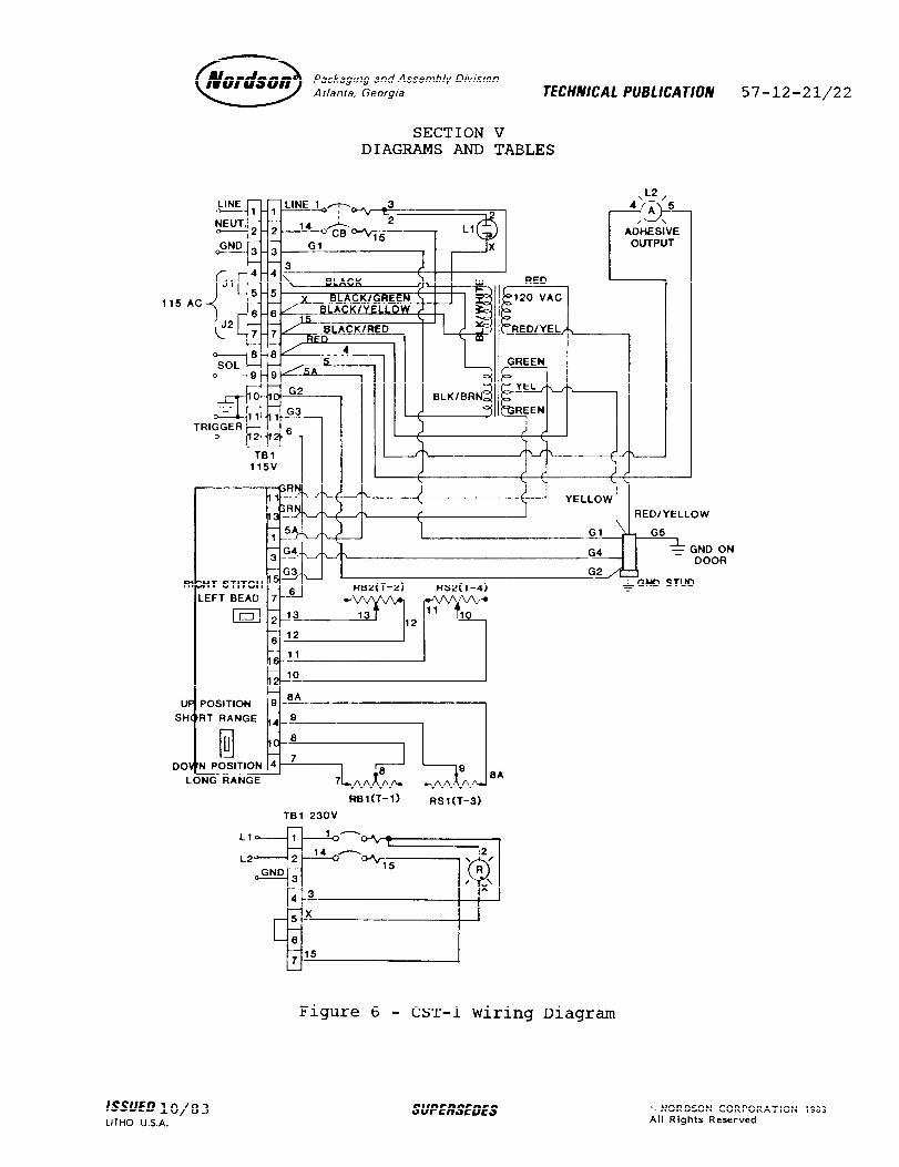
SECTION V DIAGRAMS AND TABLES
115 AC
‘, , I I
UP POSITION
LONG RANGE
Ll
L2
Rel(T-1) RSl(T-3)
TBl 23OV
Figure 6 - CST-1 Wiring Diagram
ON 3R
IssUEDlO/ LITHO lJ.S.A,
SUPERSEDES (Q NORDSON CORPORATION 1983 All Rights Reserved


0 Nordson Packagmg and Assembly Division
Atlanta, Georgia TECHNICAL PUB1 /CATION 57-12-23
TABLE 1 CST-1 HOT STITCH CONTROL
MINIMUM STITCH/GAP LENGTHS VS CONVEYOR SPEED (STANDARD UNITS)
4.5
4.0
2 3.5
3 3.0 z z 2.5
n 2.0
i 1.5
1.0
0.5
0
LINE SPEED (FPM) LINE SPEED (FPM)
38 .16
; .14
p .12
; .lO
2 .oa
g .06
.04
.02
0 0 20 40 60 80 100 12
Example: If the line speed is 40 FPM, the minimum stitch group length is .32 inches. The minimum main gap length is .72 inches. These figures are calculated as follows:
FPM - = Inches/Second 5 40 FPM/5 = 8 IPS
8 IPS x MINIMUM DURATION = MINIMUM LENGTH MINIMUM STITCH GROUP DURATION = 40 MS (.04 set) MINIMUM MAIN GAP DURATION = 90 MS (.09 set)
8 IPS x .04 set = .32 inches MINIMUM STITCH GROUP LENGTH 8 IPS x .09 set = .72 inches MINIMUM MAIN GAP LENGTH
.72= .32'
1.36" 71
/SUEDlO/ LITHO U.S.A.
SUPERSEDES i’ NORDSON CORPORATION 1983 All Rights Reserved

57-12-24 0 Nordson Packaging and Assembly D/vision
Atlanta, Georgia TECHNICAL PUBLICATION
With the IStitch ON/OFF" switch ON, the stitch group (main bead) can be broken up into a series ofbeads and gaps to reduce adhe- sive consumption. Dividing the stitch group bead length by 5
will reduce adhesive consumption 40% by providing a pattern (see below) of three beads separated by two gaps.
Dividing the minimum stitch group time interval (40 MS) by 5 yields five 8 MS intervals. At a line speed of 40 FPM, an 8 MS interval will provide a bead (or gap) .064 inches long.
t- .32” “rc--- .72” -b-r.32 +j
Reason: 8 IPS x 8 MS (or ,008 seconds) = .064 inches stitch length. 8 IPS x 8 MS (or .008 seconds) = .064 inches gap length.
NOTE: All adhesive bead lengths are proportional to the conveyor line speed.
ISSUED 1 O/ 8 3 LITHO U.S.A.
SUPERSEDES ’ NORDSON CORPORATION 1983 All Rights Reserved

0 Nordson Packaging and Assembly Dlvwon Atlanta. Georgia TECHNlCAl PUB1 ICATION 57-12-25
TABLE 2 CST-1 HOT STITCH CONTROL
MINIMUM STITCH/GAP LENGTHS VS CONVEYOR SPEED (METRIC UNITS)
80
t60!-ti-+- E70
z ;550
$40
*30
10
0 4 81216202428323640 LINE SPEED (MPM)
Example: If the line speed is length is 8 mm. The
E 3.5
E 3.0 z 0 2.5
2 2.0
m 1.5
0 4 812162024283236~ LINE SPEED (MPM)
12 MPM, the minimum stitch group minimum main gap length is
18 mm. These figures are calculated as follows:
MPM = Millimeters/Second 12
06 06 = 200 mm/set e .
200 mm/set x MINIMUM DURATION = MINIMUM LENGTH MINIMUM STITCH GROUP DURATION = 40 MS (.04 set) MINIMUM MAIN GAP DURATION = 90 MS (.09 set)
200 mm/set x .04 set = 8 mm MINIMUM STITCH GROUP LENGTH 200 mm/set ⌧ l 09 set = 18 mm MINIMUM MAIN GAP LENGTH
ISSUED 1 O/8 3 LITHO U.S.A
SUPERSEDES *) NORDSON CORPORATION 1983 All Rights Reserved

57-12-26 0 Nordson Packaging and Assembly Division
Atlanta. Georgia TECHNICAl PUB1 ICATION
With the "Stitch ON/OFF" switch OJ, the stitch group (main bead) can be broken up into a series of beads and gaps to reduce adhe- sive consumption. Dividing the stitc.h group bead length by 5 will reduce adhesive consumption 40% :by providing a pattern (see below) of three beads separated by twlo gaps.
Dividing the minimum stitch group time interval (40 MS) by 5 yields five 8 MS intervals. At a line speed of 12 MPM, an 8 MS interval will provide a bead (or gap) 1.6 mm long.
1.6mm -+I L -+I L6mm
Reason: 200 mm/set x 8 MS (or ,008 set) = 1.6 mm stitch 200 mm/set length x 8 MS (or ,008 set) = 1.6 mm gap length
NOTE: All adhesive bead lengths are proportional to the con- veyor line speed.
ISSUED lo/83 LITHO U.S.A.
SUPERSEDES NORDSON CORPORATION 1983 All Rights Reserved

0 Nordson Packaging and Assembly Division
Atlanta, Georgia TECHNICAL PUB1 ICATION 57-12-27/28
TABLE 3 CALCULATING CST-1 DIAL SETTINGS FROM MILLISECONDS
= SETTING
Example: Given MS = 400, setting = 400 -40 8 =
360 - 8 =45.
Reason: Zero corresponds to 40 MS; or 8 MS per dial increment.
scale = 840 - 40 100
T2 (RANGE 1): MSg-lgo = SETTING .
Example: Given MS = 500, setting = 500 -90 9.1 = 410 9.1 = 45.
Reason: Zero corresponds to 90 MS; scale = 1000 - 90
or 9.1 MS per dial increment. 100
T2 (RANGE 2): MS ; 8oo = SETTING
Example: Given MS = 1300, setting = 1300 - 800 = 500
9 9 = 56.
Reason: Zero corresponds to 800 MS; scale = 1700 - 800
or 9 MS per dial increment. 100
T3 and T4: MS - 5 9.5 = SETTING
Example: Given MS = 50, setting = 50 - 5 9.5 =
45 95 = 4.7.
Reason: Zero corresponds to 5 MS; scale = 100 - 5
or 9.5 MS per dial increment. 10
ISSUED 10/8 3 LITHO U.S.A.
SUPERSEDES 0 NORDSON CORPORATION 1983 All Rights Reserved


0 Nordson Packaging and Assembly Division Atlanta, Georgia TECHNICAL PUB1 ICATION 57-12-29
SECTION VI ILLUSTRATED PARTS LIST
COLUMN IDENTIFICATION
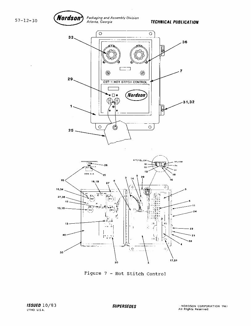
The Item No. column indicates the number assigned to the part in the associated figure. shown.
A dash is used for parts that are not
The Part No. column indicates the Nordson part number for the part. A dash signifies that the item is a nlonsaleable part or a nonsale- able subassembly of a saleable assembly.
The Description column gives the name of the part together with its dimensions and other physical properties, where appropriate.
The Req'd column indicates the quantity required per unit or assembly. When the item is listed for reference only or the quantity is not applicable, the term I'Ref" or a dash, respec- tively, appears in the column.
Parts not designated with either A or B in the Used On column are common to both versions of thg CST-1.
ISSUED 1 O/8 3 LITHO U.S.A.
SUPERSEDES (1 NORDSON CORPORATION 1983 All Rights Reserved
57-12-30 0 Nordson Packaging and Assembly Division
Atlanta, Georgia TECHNICAL PUB1 ICATION
36
0 Nordson*
:
31,32
Figure 7 - Hot Stitch Control
ISSUED lo/83 LITHO U.S.A.
SUPERSEDES ’ NORDSON CORPORATION 1983 All Rights Reserved

0 Nordson Packaging and Assembly Division
Atlanta. Georgia TECHNICAL PUB1 ICATION 57-12-31
CST-1 HOT STITCH CONTROL
Item Part Used No. No. Description Req'd On
244 507 Hot Stitch Control, CST-1, Ref A
295 042 Hot Stitch Control, CST-1, Ref B
295 286 295 280 271 586 244 498 244 495 295 044 933 100
931 096 931 180
6 933 144
933 164
933 071
939 110
931 083 933 305 981 064 983 110 981 024
983 102 933 203 933 203
7 8 9
10
981 016 295 283 244 501 244 496 939 222
11 12 13 14 15 16 17 18
939 524 939 525 981 020 983 062 984 129 983 121 983 021
115 VAC
230 VAC l Cabinet, Stitcher 1 l . Panel, Cabinet 1 l . Retainer, Circuit Board 2 l 0 Transformer w/Wire Harness 1 l * Tag, Wiring, 115 VAC 1 A l . Tag, Wiring, 230 VAC 1 B l . Strip, Marker 1 l 0 Wire Harness 1 l a* Wire, Vinyl, 22 GA, Black 24 ft l @@ Wire, Vinyl, 20 GA, Green 4.03 ft
w/Yellow l ** Terminal, Block, 12 Sta l ** Connector, 16 Sta, Female 0.0 Terminal, Pin, Female l ** Terminal, Spade l *@ Terminal, Ring-Tongue l ** Terminal, Push-on 0.. Strap, Cable l *@ Marker, Wire (PSNC) l ** Tubing, Heat Reactive l ** Terminal, Push-on, Ins
1 1
12 12 5 7
24
.07-ft 1 3 3 2 2 2 3 A 2 B 3 3 4 1 1 1 2
Screw, Pan Hd, 8-32 x 0.38 Lockwasher, #8 Screw, 6-32 x 0.19 Stand-off, 6-32 Lockwasher, Split, #6 Jumper, Terminal Jumper, Terminal Nut, Captive, 8-32 Nut, Captive, 6-32 Screw, Rnd Hd, 4-24 x 0.25
l Nameplate, CST-1 l Circuit Board, CST-1 l Insulator l Potentiometer (Stitch Length/
Stitch Gap) l Plug, Hole, 0.88 in. dia 1 l Lamp (Output) 1 l Lamp (Unit On) 1 l Screw, Pan Hd, 6-32 x 0.25 1 l Washer, Flat 4 l Nut, Hex, Brass, lo-32 2 l Lockwasher, #10 4 l Washer, Flat, Brass, #10 1
ISSUED lo/83 SUPERSEDES o NORDSON CORPORATION 1983
LITHO U.S.A. All Rights Reserved

57-12-32 0 Nordson Packaging and Assembly Division
Atlanta, Georgia TECHNICAL PUB1 ICATION
CST-1 HOT STITCH CONTR0.L (Continued)
Item Part Used No. No. Description Req'd On
19 20 21 22 23 24 25 26 27
983 120 939 616 985 101
981 729
600.168 982 010 981 008
28 29 30 31 32 33 34
35 295 061 36 981 005 37 983 103 38 984 100 39 600 006 40 295 285
981 024 242 654 242 687 981 247 295 064 939 243
Lockwasher, Split, #10 2 Breaker, Circuit, 24OV, 1A 1 Rivet, Pop, .093 x .125 4 Plate, Information, CST-1 1 Screw, lo-32 x 0.38, Pan Hd 4 Caplug 2 Tag, Inspection 1 Screw, Set, Cup, M4x6 4 Screw, Pan Hd, Self-Tap, 2 #4 x 0.38
Tag, Approval, Los Angeles 1 Screw, Pan Hd, 6-32, BL 4 Gasket, Cabinet 2.8 ft Latch, Cabinet 2 Screw w/Nylok, 0.25 - 28 x 0.63 2 Dial, Vernier 2 Potentiometer (Stitch Group/ 2
Main Gap) Support, Potentiometer 1 Screw, Rnd Hd, 5-40 4 Lockwasher, Ext Tooth, #5 4 Nut, 5-40 4 Tag, Ground 1 Tag, Switch Position 1
RECOMMENDED SPARE PARTS LIST
Part No. Description Q~Y
244 501 Circuit Board, CST-1 1 939 222 Potentiometer 1 939 243 Potentiometer 1 939 524 Lamp (Output) 1 939 525 Lamp (Unit On) 1
ISSUED 1 O/8 3 LITHO U.S.A.
SUPERSEDES (11 NORDSON CORPORATION 1983 All Rights Reserved