horizontal loading tests on model foundations retrofitted by micropiles masahiro nishitani jiro...
TRANSCRIPT

Horizontal Loading TestsHorizontal Loading Testson Model Foundationson Model Foundations
Retrofitted by MicropilesRetrofitted by Micropiles
Masahiro NISHITANIJiro FUKUITakeshi UMEBARA
IAI, PWRI Structures Research Group Foundation Engineering Team

Retrofitting of Existing Foundation by Micropiles
Limited Headroom
Widening of Footing
Existing Pile
Micropile
Bearing Layer

Presentation Outline
• Outline of horizontal loading tests on group piles
• Results of horizontal loading tests
• Results of simulation analyses for the loading tests
• Summaries
Presentation Outline
• Outline of horizontal loading tests on group piles
• Results of horizontal loading tests
• Results of simulation analyses for the loading tests
• Summaries

To Clarify the Effects of Group Piles….
→ Horizontal Loading Tests on Model Foundations
Plane of Existing Foundation with Micropiles
Micropile
Existing PileExisting Footing

Case Number of Piles
Spacing between ExistingPiles Center and
Micropiles Center
(mm)
Inclination Angle ofMicropiles (°)
1 Single Existing Pile - -
2 Single Micropile - -
3 4 Existing Piles - -
4 4 Existing Piles and 6 Micropiles 200 0
5 4 Existing Piles and 6 Micropiles 400 0
6 4 Existing Piles and 6 Micropiles 200 10
7 4 Existing Piles and 6 Micropiles 200 20
Cases of Horizontal Loading Tests

Case 1 Case 2

Case 3

Case Number of Piles
Spacing between ExistingPiles Center and
Micropiles Center
(mm)
Inclination Angle ofMicropiles (°)
1 Single Existing Pile - -
2 Single Micropile - -
3 4 Existing Piles - -
4 4 Existing Piles and 6 Micropiles 200 0
5 4 Existing Piles and 6 Micropiles 400 0
6 4 Existing Piles and 6 Micropiles 200 10
7 4 Existing Piles and 6 Micropiles 200 20
Cases of Horizontal Loading Tests

Models of Case 4 to Case 7
Existing Pile Micropile
Loading Direction
FrontRear

Case 4
Case 5

Case 6 Case 7

Diameter(mm)
Thickness(mm)
Sectional Area(cm2)
Moment of Inertia(cm4)
Existing Pile 114.3 3.5 12.18 187.0
Micropile 34.0 2.3 2.291 2.89
Specifications of Model Piles

Loading Test for Case 3
FootingSteel Bar
Jack

Presentation Outline
• Outline of horizontal loading tests on group piles
• Results of horizontal loading tests
• Results of simulation analyses for the loading tests
• Summaries

0
30
60
90
120
150
180
210
0 20 40 60 80 100Displacement of Footing mm( )
Load
kN(
)
Case1Case2Case3Case4Case5Case6Case7
Curve of Load and Displacement
-390
-330
-270
-210
-150
-90
-30
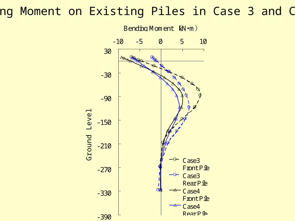
30-10 -5 0 5 10
Bending Moment kN m( ・ )
Gro
und
Leve
l cm
()
Case3Front PileCase3Rear PileCase4Front PileCase4Rear Pile
Bending Moment on Existing Piles in Case 3 and Case 4

-390
-330
-270
-210
-150
-90
-30
30-10 -5 0 5 10
Bending Moment kN m( ・ )
Gro
und
Leve
l cm
()
Case4Front PileCase4Rear PileCase6Front PileCase6Rear Pile
Bending Moment on Existing Piles in Case 4 and Case 6

-390
-330
-270
-210
-150
-90
-30
30-0.6 -0.4 -0.2 0.0 0.2
Bending Moment kN m( ・ )
Gro
und
Leve
l cm
()
Case4Front PileCase4Rear PileCase6Front PileCase6Rear Pile
Bending Moment on Micropiles in Case 4 and Case 6

- 390
- 330
- 270
- 210
- 150
- 90
- 30
30- 30 - 20 - 10 0 10
Shearing Force kN( )
Gro
un
d L
evel
cm
()
Case3Front PileCase3Rear PileCase4Front PileCase4Rear Pile
Shearing Force on Existing Piles in Case 3 and Case 4

- 390
- 330
- 270
- 210
- 150
- 90
- 30
30- 30 - 20 - 10 0 10
Shearing Force kN( )
Gro
un
d L
evel
cm(
)
Case4Front PileCase4Rear PileCase6Front PileCase6Rear Pile
Shearing Force on Existing Piles in Case 4 and Case 6

- 390
-330
-270
-210
-150
-90
-30
30-60 -30 0 30 60 90
Axial Force kN( )
Gro
und L
evel
cm(
)
Case3 Front PileCase3 Rear PileCase4 Front PileCase4 Rear PileCase6 Front PileCase6 Rear Pile
Axial Force on Existing Piles in Case 3, Case 4 and Case 6

-390
-330
-270
-210
-150
-90
-30
30-20 -10 0 10 20
Axial Force kN( )
Gro
und
Leve
l cm
()
Case4Front PileCase4Rear PileCase6Front PileCase6Rear Pile
Axial Force on Existing Piles in Case 4 and Case 6

1.5 2.01.00.50.0
1.0 1.50.50.0
Curve of Horizontal Ground Reaction and Displacement
400
300
200
100
00.0 0.5 1.0 1.5 2.0 2.5
Displacement of Pile (cm)
Hori
zonta
l G
round R
eact
ion (
KN
/m2 )
Case3 (G.L.-0.27m)Case3 (G.L.-0.57m)Case3 (G.L.-0.87m)Case4 (G.L.-0.27m)Case4 (G.L.-0.57m)Case4 (G.L.-0.87m)

Presentation Outline
• Outline of horizontal loading tests on group piles
• Results of horizontal loading tests
• Results of simulation analyses for the loading tests
• Summaries

To Study the Design Method of Group Piles with Different Diameter Piles….
→ Simulation Analyses for Loading Tests by Ductility Design Method
P
10
02
00
30
0
20
03
00
20
02
50
35
02
00
20
02
00
20
02
00
20
02
00
20
02
00
20
02
00
20
02
00
3,9
00
50
02
00
20
02
00
20
02
00
20
02
00
20
02
00
20
02
00
20
02
00
20
02
00
40
0
4,4
00Non-Linear Model
・ Ground Properties・ Flexural Rigidity of Piles

Model of Transverse Resistance of Pile
Upper Limit of Ground Reaction
Displacement
Gro
und
Rea
ctio
n
0
P HU
T an -1k HE
(m)
(N/m
2 )

kHE = a k b k kH
pHU = a p b p pU
a k , a p : Correction Factors of a Single Pile
b k , b p : Correction Factors of Group Piles
To consider the group effects…
a k b k = 1
a p (Cray Ground) = 1.0
a p b p (Sandy Ground) = S/D ( 3)≦
To consider the group effects of trailing piles…
Transverse Resistance Characteristics of Pile

Loading Direction
Trailing Piles
FrontRear
Front Pile
pHU ½ : 1

1) Study new correction factors for a single pile, fitting with Case 1 test results
2) Study new correction factors for group piles, fitting with Case 3 test results 3) Analyze Case 4 to Case 6, using new correction factors
Simulation Procedure

ak bk ap ap・bp ak bk ap ap・bp
1, 2 1.5 - 3.0 -3.0
(×2)-
6.0(×2)
-
3 1.5 2/3 - *13.0
(×2)4/3
(×2)- *2
4, 5, 6 1.5 2/3 - *13.0
(×2)4/3
(×2)- *2
*1: S/D in Transvers Direction of Loading (Less Than and Equal 3)
*2: S/D in Transvers Direction of Loading (without Upper Limit)
CaseDuctility Design Method New Correction Factors
New Correction Factors on Analyses

Model of Flexural Rigidity of Steel Pile
Curvature
Ben
ding
M
omen
t
0
Mp
MyY
Y: Yield State
(Nm
)
(1/m)φy
Fully Plastic Moment

120 1401008060200 40
1201008060200 40
1008060200 40
0
30
60
90
120
150
180
210
0 20 40 60 80 100 120 140 160
Displacement of Footing mm( )
Load
kN
()
Case3 TestCase3 AnalysisCase4 TestCase4 AnalysisCase5 TestCase5 AnalysisCase6 TestCase6 Analysis
Curve of Load and Displacement

-390
-330
-270
-210
-150
-90
-30
30-15 -10 -5 0 5 10
Bending Moment kN m( ・ )G
round
Leve
l (cm
)
Test Result on Front Pile
Test Result on Rear Pile
Analysis Resulton Front Pile
Analysis Resulton Rear Pile
-390
-330
-270
-210
-150
-90
-30
30-15 -10 -5 0 5 10
Bending Moment kN m( ・ )
Gro
und
Leve
l (cm
)Test Resulton Front PileTest Resulton Rear PileAnalysisResult
Bending Moment on Existing Piles in Case 3 and Case 4
Case 3 Case 4
-390
-330
-270
-210
-150
-90
-30
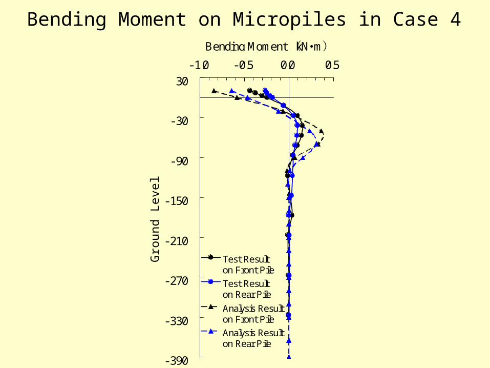
30-1.0 -0.5 0.0 0.5
Bending Moment kN m( ・ )
Gro
und
Leve
l (cm
)
Test Result on Front PileTest Result on Rear Pile
Analysis Resulton Front PileAnalysis Resulton Rear Pile
Bending Moment on Micropiles in Case 4

Depth G.L.-0.57m;
400
350
300
250
200
150
100
50
00.0 0.5 1.0 1.5 2.0 2.5
Displacement of Pile cm( )
Hori
zonta
l Gro
und
React
ion
kN/m
(2 )Test Result on Front PileTest Result on Rear PileModel on Front PileUsed in AnalysisModel on Rear PileUsed in Analysis
Curve of Horizontal Ground Reaction and Displacement
Case 3

Depth G.L.-0.57m;
300
250
200
150
100
50
00.0 0.5 1.0 1.5
Displacement of Pile cm( )
Hori
zonta
l Gro
und
React
ion
kN/m
(2 )Test Resulton Front Pile Test Resulton Rear PileModel Usedin Analysis
Curve of Horizontal Ground Reaction and Displacement
Case 4

Summaries
• Results of horizontal loading tests → Existing foundations with micropiles have a
large retrofitting effects.
→ Spacing has little effect on retrofitting.
→ Retrofitting effects are counted by installing
micropiles incliningly.
• Results of simulation analyses → It is possible to use the ductility design method
to perform retrofitting design.