horizontal directional drill analysis (splp …files.dep.state.pa.us/programintegration/pa pipeline...
TRANSCRIPT


HORIZONTAL DIRECTIONAL DRILL ANALYSIS HORSE VALLEY ROAD CROSSING
PADEP SECTION 105 PERMIT NO. E50-258 PA-PE-0002.0000-RD & PA-PE-0002.0000-RD-16
(SPLP HDD No. S2-0157)

HORSE VALLEY ROAD CROSSING PADEP SECTION 105 PERMIT NO. E50-258
PA-PE-0002.0000-RD & PA-PE-0002.0000-RD-16 (SPLP HDD No. S2-0157)
This reanalysis for the horizontal directional drill (HDD) of the Sunoco Pipeline, LP (SPLP) 16-inch and 20-inch diameter pipeline crossing of stream L7, Wetlands L1 and L2, and Horse Valley Road in Toboyne Township, Perry County, is in accordance with Stipulated Order issued under Environmental Hearing Board Docket No. 2017-009-L for HDDs listed on Exhibit 2 of the Stipulated Order. This HDD is number 12 on the list of HDDs included on Exhibit 2. This HDD was not initiated before the issuance of the Order. PIPE INFORMATION 20-Inch: 0.456 wall thickness; X-65 16-Inch: 0.438 wall thickness; X-70 Pipe stress allowances are an integral part of the design calculations performed for each HDD. ORIGINAL HORIZONTAL DIRECTIONAL DRILL DESIGN SUMMARY: 20-INCH
• Horizontal length: 1,557 foot (ft)
• Entry/Exit angle: 8-16 degrees
• Maximum Depth of cover: 50 ft
• Depth under Horse Valley Road: 14 ft
• Depth under stream: 23 ft
• Depth under wetlands: 10-50 ft
• Pipe design radius: 2,000 ft
ORIGINAL HORIZONTAL DIRECTIONAL DRILL DESIGN SUMMARY: 16-INCH
• Horizontal length: 1,597 ft
• Entry/Exit angle: 8-16 degrees
• Maximum Depth of cover: 52 ft
• Depth under Horse Valley Road: 17 ft
• Depth under stream: 24 ft
• Depth under wetlands: 10-50
• Pipe design radius: 1,600 ft GEOLOGIC AND HYDROGEOLOGIC ANALYSIS The geology at this HDD location is mapped as the Martinsburg Formation of Ordovician age. The Martinsburg Formation consists of a buff-weathered, dark gray shale with thin interbeds of siltstone, metabentonite, and fine-grained sandstone. A brown-weathered, medium-grained sandstone with interbeds of shale and siltstone is found in the middle of the formation. The basal part of the formation is generally described as a limy shale and silty limestone but no evidence of this was observed near the Horse Valley HDD. This formation is described as well bedded with thick to massive bedding in the sandstone, and thin to fissile bedding in the limestone and shale. Bedrock fracturing occurs as irregularly spaced, open and nearly vertical joints. Cleavage is dominant and highly developed in the formation. The cleavage and joints provide a secondary porosity of low magnitude and low permeability. The Martinsburg is moderately weathered to a moderate depth, resulting in small to large platy fragments. The overlying mantle is thin. From an engineering standpoint, excavation of this formation is moderately easy in the shale and difficult in the sandstone. Foundation stability is good, provided the excavation is completed to sound material.

HORSE VALLEY ROAD CROSSING PADEP SECTION 105 PERMIT NO. E50-258
PA-PE-0002.0000-RD & PA-PE-0002.0000-RD-16 (SPLP HDD No. S2-0157)
Drilling rates are described as fast. Cut slope stability is fair in the shale and good in the sandstone (Geyer and Wilshusen, 1982). Based on published mapping, Horse Valley lies within an anticline with the more resistant sandstones forming the ridges and less resistant shale forming the valley floor (Royer, 1984). Based on published geologic data, no karst features are anticipated within the subsurface profile for this HDD; therefore, the use of geophysics assessments was not considered for this HDD. Attachment 1 provides an extensive discussion on the geology and results of the geotechnical investigation performed at this location. HYDROGEOLOGY, GROUND WATER, AND WELL PRODUCTION ZONES The hydrogeologic setting of the Horse Valley Road HDD location is dominated by groundwater flow through secondary openings along geologic features including bedding planes, joints and fractures. This is supported by the observation of weathering, fractures, and joints in the geotechnical cores and identified outcrop. In addition, field measurements of local geologic structure support the published information and referenced vertical and near vertical joint sets. Joint openings are generally restricted to the first 100 to 200 feet below weathered bedrock and largely disappear at depths greater than 300 to 400 feet due to compression from the overlying material. The yield of wells drilled in the shale is typically adequate for domestic supplies ranging from 1 to 15 gallons per minute (gpm) (Lohman, 1938). In these rock types of Perry County, water-bearing zones generally occur in the secondary openings along bedding planes, joints, faults and fractures (Lohman, 1938). At this location, the HDD is relatively perpendicular to the axial plane of the anticline with strata dipping away from the axial plane (likely northwest and southeast). Accordingly, local groundwater flow within Horse Valley is anticipated to migrate downdip within the bedrock along bedding and fracture planes from areas of higher elevation to lower elevations along the valley floor. Limited well data is available relative to the Martinsburg Formation. The Reedsville Formation is considered to be a stratigraphic equivalent to the Martinsburg Formation. However, no data on the Reedsville Formation is available in Perry County (Royer, 1984). Accordingly, the following data is from the Reedsville Formation in Juniata County. The depths of 38 reported wells range from 31 to 435 feet below the ground surface (bgs) and yields ranging from 1 to 50 gallons per minute (gpm). The median depths for both domestic and nondomestic wells is 130 feet bgs. Median well yields are reported as 12 gpm for domestic wells and 20 gpm for non-domestic wells. Based on limited data, water-bearing zones are most abundant within 50 feet bgs to 150 feet bgs. Few water-bearing zones were reported below 200 feet bgs. The deepest water-bearing zone was reported at 350 feet bgs (Taylor, 1982). Groundwater was encountered in geotechnical borings at the Horse Valley HDD at depth ranging from 8.0 feet to 20 feet bgs. The production zone for waters wells in a bedrock formation is from the well bottom to highest point of water inflow from the water bearing seams, joints, and fractures in the rock formation. Attachment 1 provides an extensive discussion on the hydrogeology, and results of the geotechnical investigations performed at this location. INADVERTENT RETURN (IR) DISCUSSION An HDD has not been initiated at this location. No IRs were reported along the alignment of the HDD S2-0157 on the list of IRs for Mariner East I as documented in the IR Preparedness, Prevention and Contingency (PPC) Plan for Perry County. The Mariner 1 pipeline was installed by conventional construction methods at this location.

HORSE VALLEY ROAD CROSSING PADEP SECTION 105 PERMIT NO. E50-258
PA-PE-0002.0000-RD & PA-PE-0002.0000-RD-16 (SPLP HDD No. S2-0157)
Sunoco Pipeline, L.P. (SPLP) HDD consultants reviewed the HDD design and geotechnical data for this area and determined that the risk of IRs to the waters and wetlands overlying the HDD could be reduced by increasing the depth of the HDD. The results of the new geotechnical core borings at the entry and exit points show the revised HDD profile will encounter and transition through shale for the entire profile. Overall rock quality parameters improve as depth below ground increases. The west core data show mudstone at top of bedrock with a recovery value of 50, and RQD value of 22, improving as depth increases with recovery values consistently at 100 and RQD values ranging from 28-90. At maximum profile depth the recovery value is 100 and RQD value is 65. This is indicative of moderate to good overall rock integrity and strength at profile depth. The east core data, which should be representative of the majority of the HDD profile under natural resources shows the top of bedrock as shale with a recovery value of 100 and RQD value of 90. Proceeding to profile depth the HDD will enter and progress through shale with recovery values consistently at 100, and RQD values ranging from 90 to 100. At maximum profile depth the recovery value is 100 and RQD value is 100, indicative of good overall rock integrity and excellent strength at profile depth. As such, the revised profiles present a reduced risk of creating an IR. POTENTIAL FOR AND MANAGEMENT OF PRODUCED GROUNDWATER Due to the approximate 80 ft of elevation difference between the HDD exit (west) side, and HDD entry (east) side, the potential for producing groundwater during the HDD exists once the pilot hole has progressed west of Horse Valley Road approximately 1,920 ft into the profile and above 1,094 ft of elevation on the exit radius. This is approximately 250 ft before completion of the pilot hole at the HDD exit. The elevation difference is not extreme and water produced during the pilot and reaming phases will be utilized in the continuing HDD process and decrease the amount of water imported at the HDD rig. Operators will adjust the drilling fluid viscosity to account for produced water to ensure the returns are maintained as a flowable slurry. Excess produced groundwater, or groundwater produced during non-drilling periods will be captured, filtered, and discharged to the land surface at the edge of the temporary workspace. If the means of filtration is insufficient to prevent the discharge of potentially turbid water to waters of the Commonwealth, then the produced water will be pumped to storage tanks staged in the temporary workspace at the HDD entry or in the temporary workspace adjacent to Horse Valley Road, and then hauled away for treatment and disposal. Assuming an average daily rate of 275 ft of progress, it will take seven continuous drilling days to achieve 1,920 ft of progress on the pilot hole. Prior to reaching this extent and 1,094 ft of elevation on the pilot hole, the contractor will have pre-prepared filtration structures and filtration bags in place to capture, filter, and discharge produced water. Portable storage tanks will be stage on site if the filtration system fails to clean the produced water sufficiently for discharge. Attachment 2 contains the water control and filtration details and location on the applicable section of the project’s Erosion and Sediment Control Plans.
If groundwater discharges through the annulus of the HDD persist after the pipeline is pulled into place, then SPLP will grout the annulus surrounding the pipeline with bentonite plugs using tremie pipes pushed into the profile a minimum of 15 ft into the annulus, with the high viscosity grout then pumped into place until it’s pressurized back to the annulus opening. ADJACENT FEATURES ANALYSIS The crossing of Horse Valley Road is located in rural Perry County, approximately 2.2 miles east-northeast of the community of Waterloo, PA. This HDD location is within unmanaged deciduous woodlands, wetlands, and an agricultural field. The HDD would cross under two (2) exceptional value

HORSE VALLEY ROAD CROSSING PADEP SECTION 105 PERMIT NO. E50-258
PA-PE-0002.0000-RD & PA-PE-0002.0000-RD-16 (SPLP HDD No. S2-0157)
(EV) wetlands (L1 & L2) and one (1) stream (L7). Wetlands L1 and L2 are designated “EV” due to wild trout watershed contribution. Stream L7 is a designated high quality-cold water fishery (HQ-C). A 0.35 acre impoundment occurs approximately 40 ft north of the HDD location and a 0.43 acre impoundment occurs approximately 110 feet south of the HDD location. SPLP has identified all landowners with property located within 450 ft of the HDD alignment. There are four (4) individual landowners with properties located within 450 ft of the HDD alignment. SPLP sent each of these landowners a notice letter via both certified and first class mail on October 30, 2017, that included an offer to sample the landowner’s private water supply/well in accordance with the terms of the Order and the Water Supply Assessment, Preparedness, Prevention and Contingency Plan. The letter also requested that each landowner contact the Right-of-Way agent for the local area and provide SPLP with information regarding: (1) whether the landowner has a well; (2) where that well is located, and its depth and size if known; and (3) whether the landowner would like to have the well sampled. In accordance with paragraph 10 of the Order, copies of the certified mail receipts for the letters sent to landowners have been provided to Karyn Yordy, Executive Assistant, Office of Programs at the Department’s Central Office. SPLP’s outreach has confirmed that no private water wells occur within 450 ft of the HDD profile. Attachment 3 presents an illustration of water supply wells adjacent to the 450-ft buffer of the HDD profile. According to records at the Pennsylvania Department of Environmental Protection, two non-community public water supply wells exist in the vicinity to the HDD, one located approximately 1,600 ft south of the HDD location, and a second located approximately 800 ft north of the HDD location. The well located south of the HDD is owned and operated by Wildwood Family Campground. This well is located hydraulically upgradient of the HDD location and is outside the zone of potential effect of the HDD construction methods. Since the movement of groundwater is a subdued reflection of the overlying topography, the recharge for this well would likely derive from groundwater movement from the south, east, and west; therefore the HDD construction at 1,600 ft has no potential to affect water resources for this well. On January 2, 2018, agents for SPLP investigated the two occupied properties north of the HDD location. A non-public community water well was not observed at either location. Both locations, as shown on the water supply illustration, have private wells that serve single, residential home sites. Based upon the understanding of the groundwater levels and movement through the overburden and subsurface bedrock fissures and bedding plane partings as described in the hydrogeology report, SPLP believes that HDD activities could affect individual well use during active drilling for wells located within 150 linear ft. of the profile. Neither of these wells are within this zone of concern, and both are located upgradient and west of the valley floor; therefore, the source recharge for these wells would derive from groundwater movement from higher elevations to the west, not from the direction of the HDD profile where is crossed the valley floor. ALTERNATIVES ANALYSIS As required by the Order, the reanalysis of S2-0157 includes an evaluation of open cut alternatives and a re-route analysis. As part of the PADEP Chapter 105 permit process for the Mariner II East Project, SPLP developed and submitted for review a project-wide Alternatives Analysis. During the development and siting of the project, SPLP considered a number of different routings, locations, and designs to determine whether there was a practicable alternative to the proposed impact. SPLP performed this determination through a sequential review of routes and design techniques, which concluded with an alternative that has the least environmental impacts, taking into consideration cost, existing technology, and logistics. The baseline route provided for the pipeline construction was to cross every wetland and stream on the project by open cut construction procedures. The Alternatives Analysis submitted to PADEP conceptually analyzed the potential feasibility of any alternative to baseline route trenched
HORSE VALLEY ROAD CROSSING PADEP SECTION 105 PERMIT NO. E50-258
PA-PE-0002.0000-RD & PA-PE-0002.0000-RD-16 (SPLP HDD No. S2-0157)
resource crossings (e.g., reroute, conventional bore, HDD). The decision-making processes for selection of the HDD instead of an open cut crossing methodology is discussed thoroughly in the submitted alternatives analysis and was an important part of the overall PADEP approval of HDD plans as currently permitted. As described below, the open cut and re-route analyses have confirmed the conclusions reached in the previously submitted Alternatives Analysis. Open-cut Analysis Sunoco Pipeline, L.P. (SPLP) specifications require a minimum of 48-inches of cover over the installed pipelines. To meet these cover requirements, during construction through the stream and wetlands would require a minimum authorized open cut work space 75 ft in width to accommodate the 16 and 20-inch pipelines, allowing for each pipeline to be installed with sufficient separation for integrity management. The assessed area of impact by this open cut plan would directly affect approximately 0.02 acres of state water bottoms, 1.26 acres of emergent wetland, 0.49 acres of shrub-scrub wetland, and 0.42 acres of forested wetland. Due to the existing saturated ground conditions, a significant volume of produced groundwater will fill all the excavations during the open cut process. These water volumes can be pumped to a discharge filtration structure; however, the current feasible filtration ability does not exceed 50 microns, therefore, cloudy water (from suspended fine clay and silt particles) would be discharged to the watershed regardless of all control methods employed for the entire duration of this crossing until completion. The crossing distance of the emergent and forested wetlands, a distance of approximately 1,250 ft, is beyond the technical limits of a conventional auger bore. Re-Route Analysis The pipeline route as currently permitted follows parallel to one (1) existing Sunoco pipeline. In accordance with state and federal guidance, SPLP has routed the Project to be co-located with existing pipeline and other utility corridors to avoid new “greenfield” routing alignments, to the maximum extent practicable. This avoids and minimizes new and permanent impacts on previously undisturbed land, land use encumbrance, and site-specific and cumulative impacts on land, environmental, and community resources. There are no existing utility corridors to the north that would provide a practical alternative route. Any alternate route considered north of the existing utility corridor would require the clearing of a new “greenfield” corridor which would significantly increase impacts to natural resources in comparison to the exiting route and HDD location. An existing cleared utility corridor lies approximately 725 feet to the south of the SPLP easement and general parallels the SPLP easement at a near equivalent offset parallel for miles to the east and west of the HDD location. Utilizing this corridor would move the project away from the existing Sunoco pipeline while transecting the same resources. Immediate to Horse Valley Road, this easement bisects two (2) residential locations and is in near proximity to two others; therefore in comparison to the proposed HDD location, this alternate route is not preferred. RECONSIDERATION OF THE HORIZONTAL DIRECTIONAL DRILL As stated above, SPLP HDD consultants reviewed the HDD designs and geotechnical data for this location. Based upon this review, it was determined that the risk of IRs to waters of the Commonwealth overlying the HDD could be reduced by increasing the depth of the original permitted HDD profile. Additional geologic investigations have been completed and utilized in the redesign of the planned HDD.

HORSE VALLEY ROAD CROSSING PADEP SECTION 105 PERMIT NO. E50-258
PA-PE-0002.0000-RD & PA-PE-0002.0000-RD-16 (SPLP HDD No. S2-0157)
The redesign adjusts the HDD profile deeper to place the HDD pathway through bedrock having better structural integrity than a shallower profile and increases the overall length of the HDD due to pipe design requirements. A summary of the redesign factors is provided below. Revised Horizontal Directional Drill Design Summary: 20-inch
• Horizontal length: 2,170 foot (ft)
• Entry/Exit angle: 12-18 degrees
• Maximum Depth of cover: 110 ft
• Depth under Horse Valley Road: 76 ft
• Depth under stream: 84 ft
• Depth under wetlands: 60-80 ft
• Pipe design radius: 2,400 ft
Revised Horizontal Directional Drill Design Summary: 16-inch
• Horizontal length: 2,125 foot (ft)
• Entry/Exit angle: 12-18 degrees
• Maximum Depth of cover: 100 ft
• Depth under Horse Valley Road: 70 ft
• Depth under stream: 76 ft
• Depth under wetlands: 60-70 ft
• Pipe design radius: 2,000 ft As shown on Figure 2, the redesigned HDD profile for the 20-inch pipeline is 613 ft longer, with a depth of cover below the streams and wetlands increased by 30-59 ft from the permitted design. In addition, the entry/exit angles have been increased allowing for a sharper and quicker descent into more competent rock. As shown on Figure 4 the redesigned HDD profile for the 16-inch pipeline is 528 ft longer, with a depth of cover below the streams and wetlands increased by 20-53 ft and designed for a sharp and quick entry and exit from the horizontal depth. The redesign of the HDD will not prevent all IRs. IRs are common on entry and exit of the drilling tool and other measures are required to minimize IR potential. In particular, upon the start of these HDDs, Sunoco will employ the following HDD best management practices:
• SPLP will implement rotational drilling of the pilot hole until competent bedrock is reached, such that the initial drilling at entry is performed at fluid pressures less than those required to operate the mud motor drive;
• SPLP will require and enforce the use of annular pressure monitoring during the drilling of the pilot holes, which assists in immediate identification of pressure changes indicative of loss of return flows or over pressurization of the annulus to manage development of pressures that can induce an IR;
• SPLP inspectors will ensure that an appropriate diameter pilot tool, relative to the diameter of the drilling pipe, is used to ensure adequate “annulus spacing” around the drilling pipe exits to allow good return flows during the pilot drilling;
• SPLP will implement short-tripping of the reaming tools as return flow monitoring indicates to ensure an open annulus is maintained to manage the potential inducement of IRs;

HORSE VALLEY ROAD CROSSING PADEP SECTION 105 PERMIT NO. E50-258
PA-PE-0002.0000-RD & PA-PE-0002.0000-RD-16 (SPLP HDD No. S2-0157)
• SPLP will require monitoring of the drilling fluid viscosity, such that fissures and fractures in the subsurface are sealed during the drilling process;
• During the reaming phase, the use of Loss Control Materials (LCMs) can be implemented if indications of a potential IR are noted or an IR is observed;
• If LCMs prove ineffective to mitigate loss of returns or IRs, then grouting of the pilot hole may be implemented, and
• SPLP drilling and environmental managers will be onsite when the pilot phase for each HDD nears 1,920 ft of progress and passes 1,094 ft of elevation, and SPLP will provide the DEP Southcentral Regional Office at least three (3) days advance notice of the date SPLP anticipates reaching this stage of the HDD.
CONCLUSION It is SPLP’s intent to modify the original profile design and to pursue a deeper and longer HDD profile. Figure 1 and 3 in Attachment 4 presents the original HDD plan and profiles. Figure 2 and 4 in Attachment 4 present the revised HDD plan and profiles.

HORSE VALLEY ROAD CROSSING PADEP SECTION 105 PERMIT NO. E50-258
PA-PE-0002.0000-RD & PA-PE-0002.0000-RD-16 (SPLP HDD No. S2-0157)
ATTACHMENT 1
GEOLOGY AND HYDROGEOLOGICAL EVALUATION REPORT

We answer to you. 3020 Columbia Avenue, Lancaster, PA 17603 ● Phone: (800) 738-8395 E-mail: [email protected] ● Website: rettew.com
January 18, 2018 Mr. Matthew Gordon
Sunoco Pipeline, L.P. 535 Fritztown Road Sinking Spring, PA 19608 RE: Sunoco Pipeline, L.P. Pipeline Project - Mariner East II
Horse Valley Road Horizontal Directional Drill Location (S2-0157) Hydrogeological Re-evaluation Report
Toboyne Township, Perry County, Pennsylvania RETTEW Project No. 096302011
EXECUTIVE SUMMARY
1. The Corrected Stipulated Order dated August 10, 2017 requires a re-evaluation of the Horse Valley Road Horizontal Directional Drill (HDD) location, including a geologic report.
2. The Horse Valley Road HDD is underlain by clastic sedimentary rocks of the Martinsburg Formation (Om) of Ordovician age.
3. Geologic mapping, published reports, and field mapping indicate steeply dipping beds with jointing and fracturing.
4. Water-bearing zones generally occur in secondary openings along bedding planes, joints, and fractures. Water-bearing zones in the Reedsville Formation, a stratigraphic equivalent of the Martinsburg Formation in neighboring Juniata County, are frequent within 50 to 150 feet of the ground surface.
5. To date, no HDD operations have started for the proposed 16-inch or 20-inch pipelines.
6. Based on the hydro-structural characteristics of the underlying geology, and proposed HDD profile, the Horse Valley Road HDD is susceptible to the inadvertent return (IR) of drilling fluids during HDD operations for the planned 16-inch and 20-inch drills. The redesigned HDD profiles, engineering controls and HDD best management practices (BMPs) during drilling operations will be used to reduce the risk of an IR. Proposed engineering controls and BMPs include annular pressure monitoring (APM), use of loss control materials (LCMs) and/or grouting if indications of an IR or fluid loss are observed, appropriate tooling to allow for return of drilling fluids, short-tripping of reaming tools to maintain an open annulus, and monitoring of drilling fluid viscosity.
1.0 INTRODUCTION
The purpose of this report is to describe the geologic and hydrogeologic setting of the Horse Valley Road (S2-0157) HDD location (the site) on the Sunoco Pipeline, L.P. (SPLP) Pennsylvania Pipeline Project - Mariner East II (PPP-ME2) Project. The Horse Valley Road HDD is located in Toboyne Township, Perry County, Pennsylvania (refer to Figure 1). The HDD was designed to be drilled under Horse Valley Road, a
Engineers
Environmental Consultants
Surveyors
Landscape Architects
Safety Consultants

Page 2 of 9 Sunoco Pipeline, L.P. January 18, 2018 RETTEW Project No. 096302011
small stream (S-Q69) and a wetland complex. This re-evaluation report is part of the response to the Corrected Stipulated Order dated August 10, 2017.
The proposed HDD profiles were lengthened and deepened on January 3, 2018 to provide additional protective cover beneath the stream and wetland complex. The HDD exit on the western side of the profile is at an elevation of approximately 1,175 feet above mean sea level (AMSL) for the proposed 16-inch drill and 1,178 feet AMSL for the proposed 20-inch drill. The HDD entry on the eastern side of the profile is at an elevation of approximately of 1,093 feet AMSL for the proposed 16-inch drill and 1,094 feet AMSL for the proposed 20-inch drill. The HDD is located approximately between Stations 8614+00 and 8635+00 along the pipeline. The horizontal length of the proposed 16-inch drill is 2,125 feet and 2,170 feet for the proposed 20-inch drill. The inclination of the entry and exit angles has been increased to install the pipe through protective soils, residual soils, and bedrock, and in closer proximity to the entry and exit points than the original, shallower profiles. Due to the approximate 82-foot (16-inch) and 84-foot (20-inch) elevation difference between the HDD entry and exit, the potential for produced groundwater exists. However, the difference in elevation is not extreme, and water produced during the pilot and reaming phases will be recycled. This water reuse will allow for the continual HDD process to reduce the amount of water required at the HDD rig, while simultaneously allowing the drilling fluid viscosity to be adjusted to account for free water that ensures that the returns are maintained as a flowable slurry. Copies of the revised HDD profiles are included in Attachment 1.
2.0 GEOLOGY AND SOILS
Based upon publications by the Pennsylvania Bureau of Topographic and Geologic Survey (BTGS, 2001 and Sevon, 2000), the site is in the Appalachian Mountain Section of the Ridge and Valley Physiographic Province of Pennsylvania, which is regionally underlain by sedimentary rocks consisting of sandstone, siltstone, shale, conglomerate, limestone, and dolomite. Local topography is characterized by long narrow ridges and broad to narrow valleys (Royer, 1984 and Sevon, 2000).
According to the United States Department of Agriculture (USDA) Soil Surveys of Perry County, Pennsylvania, soils within the vicinity of the drill path for HDD S2-0157 consist of 11 distinct soil units. A USDA map that depicts the mapped area, along with the soil profile descriptions, is included as Attachment 2.
The site geology is mapped as the Martinsburg Formation (Om) of Ordovician age. The Martinsburg Formation consists of a buff-weathered, dark gray shale with thin interbeds of siltstone, metabentonite, and fine-grained sandstone. A brown-weathered, medium-grained sandstone with interbeds of shale and siltstone is found in the middle of the formation. The basal part of the formation is generally described as a limy shale and silty limestone but no evidence of this was observed near the Horse Valley HDD. This formation is described as well bedded with thick to massive bedding in the sandstone, and thin to fissile bedding in the limestone and shale. Bedrock fracturing occurs as irregularly spaced, open and nearly vertical joints. Cleavage is dominant and highly developed in the formation. The cleavage and joints provide a secondary porosity of low magnitude and low permeability. The Martinsburg is moderately weathered to a moderate depth, resulting in small to large platy fragments. The overlying mantle is thin. From an engineering standpoint, excavation of this formation is moderately easy in the shale and difficult in the sandstone. Foundation stability is good, provided the excavation is completed to sound material. Drilling rates are described as fast. Cut slope stability is fair in the shale and good in the sandstone (Geyer

Page 3 of 9 Sunoco Pipeline, L.P. January 18, 2018 RETTEW Project No. 096302011
and Wilshusen, 1982). Based on published mapping, Horse Valley lies within an anticline with the more resistant sandstones forming the ridges and less resistant shale forming the valley floor (Royer, 1984).
3.0 HYDROGEOLOGY
Groundwater at the site occurs in a fractured sedimentary bedrock aquifer system within the geology described in Section 2.0. Secondary porosity related to the joints, fractures and bedding planes is the primary path for ground water flow. Joint openings are generally restricted to the first 100 to 200 feet below weathered bedrock and largely disappear at depths greater than 300 to 400 feet due to compression from the overlying material. The yield of wells drilled in the shale is typically adequate for domestic supplies ranging from 1 to 15 gallons per minute (gpm) (Lohman, 1938). In these rock types of Perry County, water-bearing zones generally occur in the secondary openings along bedding planes, joints, faults and fractures (Lohman, 1938). At this location, the HDD is relatively perpendicular to the axial plane of the anticline with strata dipping away from the axial plane (likely northwest and southeast). Accordingly, local groundwater flow within Horse Valley is anticipated to migrate downdip within the bedrock along bedding and fracture planes from areas of higher elevation to lower elevations along the valley floor.
Limited well data is available relative to the Martinsburg Formation in Perry County. The Reedsville Formation is considered to be a stratigraphic equivalent to the Martinsburg Formation. However, no data on the Reedsville Formation is available in Perry County (Royer, 1984). As a result, data from the Reedsville Formation in adjacent Juniata County is summarized as follows. The depths of 38 reported wells range from 31 to 435 feet below the ground surface (bgs) and yields ranging from 1 to 50 gpm. The median depths for both domestic and nondomestic wells is 130 feet bgs. Median well yields are reported as 12 gpm for domestic wells and 20 gpm for non-domestic wells. Based on limited data, water-bearing zones are most abundant within 50 feet bgs to 150 feet bgs. Few water-bearing zones were reported below 200 feet bgs. The deepest water-bearing zone was reported at 350 feet bgs (Taylor, 1982). Groundwater was encountered in geotechnical borings at the Horse Valley HDD at depth ranging from 8.0 feet to 20 feet bgs as discussed in Section 5.0
Well records reviewed within a 0.5-mile radius of the HDD location were obtained from the Pennsylvania Groundwater Information System (PaGWIS). A single well record was available and is summarized below. The well location is shown on Figures 2 and 3.
Well No. Well Use Casing Depth (feet)
Total Depth (feet)
Water Level (feet)
Yield (gpm)
505314 DOMESTIC 59 175 150 30
As a condition of the corrected stipulated order, other Sunoco subcontractors have researched private water supplies located within 450 feet of the Horse Valley HDD. No private wells were identified within 450 feet of the Horse Valley HDD; however, one well was identified approximately 483 feet south of the HDD exit as shown on the figure in Attachment 3. Well construction details were not available.

Page 4 of 9 Sunoco Pipeline, L.P. January 18, 2018 RETTEW Project No. 096302011
4.0 FRACTURE TRACE ANALYSIS
Fracture traces underlying, or in close proximity to, the site were evaluated using historical aerial photographs from the years 1995 through 2015 (Google Earth, 2017) and the Blairs Mills, Pennsylvania Geologic Quadrangle Maps from Atlas 61 (Berg and Dodge, 1981 and Royer, 1984). The photographs, publications and maps were reviewed to approximate the locations of natural linear fracture trace features or lineaments expressed on the ground surface. The linear features may be the surficial representation of deeper high angle fractures, joints, faults or bedding planes within the subsurface which can transmit groundwater through the fractured bedrock aquifer at the site.
Figures 2 and 3 show the results of the fracture trace analysis overlain on the geologic map of the site and an aerial basemap. Eight fracture traces were identified within close proximity to the Horse Valley Road HDD that are likely related to the primary geologic structure. Four of the fracture traces trend approximately northeast-southwest (NE-SW), parallel to geologic strike. Four perpendicular fracture traces trend northwest-southeast (NW-SE) and may represent joint sets. Due to the nature of the ridges and folded geology near the site, the bedding-parallel fracture traces trend approximately NE-SW. Bedding-perpendicular fracture traces were identified in the approximately NW-SE fracture lineaments which are presumed to be stress-related joint sets. General surface drainage patterns near the site are characterized by linear stream reaches trending NE-SW or NW-SE that reflect the general geologic structure.
5.0 GEOTECHNICAL EVALUATION
Two geotechnical drilling investigations were performed at the site; the first was performed in October 2014 and the second in August 2017. The 2014 test borings were advanced by hollow-stem augers and NQ-sized wireline rock coring techniques. These borings are designated as SB-01 and SB-02. The 2017 test borings were advanced using the mud rotary method and are designated B3-5E and B3-5W. Soil, residual soil and weathered bedrock were sampled using split-spoon samplers. Geotechnical boring logs are included in Attachment 1.
Boring SB-01 was located approximately 125 feet southeast of the HDD entry on the west side of the profile. Boring SB-02 was located approximately 850 feet east-southeast of the HDD entry and near the midpoint of the profile. Boring B3-5W was located near the HDD exit and B3-5E was located near the HDD entry. The locations of the borings are depicted on Figure 2 and Figure 3.
In general, the subsurface profile at the site, as observed in the borings, is described as follows:
Soil and residual soil depths vary from boring to boring; 18.5 feet at SB-01, 15.0 feet at SB-02, 29.0 feet at B3-5W, and 13.0 feet in B3-5E. The residual soils are described as follows:
o Boring SB-01: LEAN CLAY (CL) with silty clay, little fine sand and a trace to little fine shale gravel from the ground surface to 13.5 feet bgs. CLAYEY SAND (SC) with some silty clay, and some fine to coarse gravel comprised of shale from 13.5 feet bgs to 18.5 feet bgs. Auger refusal was encountered at 20.0 feet bgs. Groundwater was observed at 17.5 feet bgs.
o Boring SB-02: Silty SAND (SM) and Clayey SAND (SC) with little to some unweathered shale to 15.9 feet. Auger refusal was encountered at 15.0 feet bgs. Groundwater was observed at 8.0 feet bgs.

Page 5 of 9 Sunoco Pipeline, L.P. January 18, 2018 RETTEW Project No. 096302011
o Boring B3-5E: Lean CLAY (CL) composed of weathered shale. Groundwater was encountered at 20.0 feet bgs.
o Boring B3-5W: Lean CLAY (CL). Groundwater was encountered in this boring.
At depths of auger or split-spoon refusal, and to the total depth of the NQ cores, weathered bedrock and bedrock were encountered and are described as follows:
o Boring B3-5E: B3-5E was completed to a total depth of 85.0 feet bgs. From 15.0 feet to 85.0 feet bgs, fresh to moderately weathered SHALE was observed. The SHALE is described as thinly bedded with moderately dipping to vertical joints. The joints are very close to close, smooth to rough, open to tight with some iron staining and some are infilled with calcite. Rock quality designations (RQDs) in the shale were very poor to excellent (0% to 100%) and generally increase with depth. Recoveries were good to excellent (54 inches to 60 inches) and consistent throughout the coring runs. Groundwater was encountered at 20.0 feet bgs and a loss of circulation was noted at 46.0 feet bgs.
o Boring B3-5W: B3-5W was completed to a depth of 135.0 feet bgs. From 29.0 feet to 45.0 feet bgs, severely weathered and fractured SHALE was encountered. From 45.0 feet to 115.0 feet bgs, slightly to severely weathered SHALE was observed. In this interval, joints are described as horizontal to vertical with close to moderately close spacing with some calcite infilling. From 115.0 feet to 135.0 feet bgs, fresh to slightly weathered SHALE with high angle to vertical bedding. Joints are described as low angle to vertical and close to moderately spaced with some calcite infilling. RQDs were very poor to excellent (0% to 90%). The highest RQDs were observed from 110.0 feet to 120.0 feet bgs. Recoveries were fair to excellent (32 inches to 60 inches) and generally increase with depth. Full recoveries (60 inches) were obtained from 85.0 feet to 135.0 feet bgs. Groundwater was not observed in this boring.
Unconfined compressive strength testing was performed on core samples, and the test results are summarized in the table below.
Boring Sample Depth (feet bgs) Compressive Strength (psi)
B3-5W 75 14,990
B3-5W 91 2,436
B3-5W 95 1,247
B3-5W 115 7,454
B3-5W 134 1,504
B3-5E 34 9,496
B3-5E 54 3,337
B3-5E 74 6,939
B3-5E 84 7,054

Page 6 of 9 Sunoco Pipeline, L.P. January 18, 2018 RETTEW Project No. 096302011
Please note that RETTEW did not oversee or direct the geotechnical drilling program associated with the Horse Valley Road HDD, including but not limited to, the selection of boring locations, determination of location, determination of surface elevation, target depths, observations of rock cores during drilling operations, or preparation of boring logs. The geotechnical reports, boring logs, and core photographs that resulted from these programs were generated by other Sunoco Pipeline, L.P. contractors. RETTEW relied on these reports and incorporated their data into the general geologic and hydrogeologic framework of the analysis of the Horse Valley Road HDD in this report.
6.0 FIELD OBSERVATIONS
A field investigation was performed by a RETTEW geologist on October 14, 2017 to identify rock outcrops for fracture fabric analysis, possible ground-truthing of fracture traces identified during the desktop evaluation, and to identify potential sensitive receptors to IRs. A small outcrop was identified near the HDD entry as shown on Figures 2 and 3. The outcrop consists of gray shale with evidence of extensive weathering (oxidation) along the bedding planes. The strike of bedding at this outcrop is 51° with a dip angle of 35°SE. The average strike of the primary joint set is 154° with a dip angle of 79°SW. The strike and dip of bedding is consistent with published geologic data, mapping, and fracture traces identified in Section 4.0. The near vertical joints are consistent with the published geologic and geotechnical core data presented in Section 5.0. No additional sensitive receptors to IRs beyond the previously mapped streams and wetlands were identified during the site reconnaissance.
7.0 CONCEPTUAL HYDROGEOLOGIC MODEL AND CONCLUSION
Based on published geologic and hydrogeologic information, and the evaluation of geotechnical borings from the site, the Horse Valley Road HDD location is underlain by clastic sedimentary rocks of the Martinsburg Formation. The hydrogeologic setting is dominated by groundwater flow through secondary openings along geologic features including bedding planes, joints and fractures. This is supported by the observation of weathering, fractures, and joints in the geotechnical cores and identified outcrop. In addition, field measurements of local geologic structure support the published information and referenced vertical and near vertical joint sets. Well records indicate that water-bearing zones in the equivalent Reedsville Formation are common from depths of 50 feet to 250 feet bgs.
The originally proposed 16-inch and 20-inch HDD profiles were relatively shallow at the entry and exit points, and passed through both the unconsolidated overburden and fractured bedrock. Based on the hydro-structural characteristics of the underlying geology described in this report and the proposed HDD profiles, the Horse Valley Road HDD site is susceptible to the inadvertent return of drilling fluids during HDD operations. As a result, the HDD profile has been redesigned to allow for deeper crossings beneath the wetland complex and stream. The inclination of the entry and exit angles has been increased to allow the pipe to be installed through the protective soils, residual soils, and bedrock in closer proximity to the entry and exit points than the original, shorter and shallower profile.
The redesigned HDD profiles will not prevent all IRs. From a geologic perspective, the longer and deeper profile, in conjunction with the proposed engineering controls and/or drilling best management practices BMPs, will be used to reduce the risk of an IR. In conjunction with the redesigned profile, several engineering controls and BMPs have been proposed for the Horse Valley Road HDD that are described below:

Page 7 of 9 Sunoco Pipeline, L.P. January 18, 2018 RETTEW Project No. 096302011
1. APM will implemented during pilot hole drilling and reaming operations. APM will be used to
identify pressure changes indicative of loss of fluid returns or over pressurization. Based on APM
monitoring, LCMs will be implemented if indications of an IR or loss of returns are observed. If
LCMs are ineffective, grouting of the pilot hole may be implemented;
2. Selection of appropriate diameter pilot tools to maintain adequate spacing around the drilling
pipe to allow for return flows during pilot drilling;
3. Short-tripping of the reaming tools based on monitoring of returns to maintain an open annulus
in the boring; and
4. Monitoring of drilling fluid viscosity to maintain drilling for sealing fractures.

Page 8 of 9 Sunoco Pipeline, L.P. January 18, 2018 RETTEW Project No. 096302011
8.0 REFERENCES
Berg, T. M., and Dodge, C. M., compilers and eds., 1981, Atlas of preliminary geologic quadrangle maps of Pennsylvania: Pennsylvania Geological Survey, 4th ser., Map 61, 636 p.
Geyer, A. R., and P. J. Wilshusen, 1982, Engineering Characteristics of the Rocks of Pennsylvania, Pennsylvania Topographic and Geologic Survey, Environmental Geology Report 1, Second Edition, 300 pages.
Google Earth Pro, 2017, Version 7.1.8.3036, November 27, 2017.
Lohman, S.W., 1938, Ground Water in South-Central Pennsylvania, Commonwealth of Pennsylvania, Topographic and Geologic Survey, Bulletin W 5, 315 pages.
Pennsylvania Bureau of Topographic and Geologic Survey, Department of Conservation and Natural Resources, 2001, Bedrock Geology of PA, Edition: 1.0, Digital Map. Retrieved from internet September 18, 2017; HTTP://www.dcnr.state.pa.us/topogeo/map1/bedmap.aspxDL Data: Page oexp.zip [HTTP://www.dcnr.state.pa.us/topogeo/map1/bedmap.aspx].
Pennsylvania Department of Conservation and Natural Resources, Pennsylvania Groundwater Information System (PaGWIS) database, website address: http://www.dcnr.pa.gov/Con-servation/Water/Groundwater/PAGroundwaterInformationSystem/Pages/default.aspx, accessed November 28, 2017.
Royer, D.W., 1984, Summary of Groundwater Resources of Perry County, Pennsylvania, Pennsylvania Geologic Survey, 4th Series, Water Resource Report 54, 70 pages.
Sevon, D., 2000, Map 13, Physiographic Provinces of Pennsylvania, Pennsylvania Bureau of Topographic and Geologic Survey, Harrisburg, Pennsylvania.
Taylor, L. E., 1982, Groundwater Resources of the Juniata River Basin, Pennsylvania, Pennsylvania Geologic Survey, 4th Series, Water Resource Report 54, 144 pages.
United States Department of Agriculture, 2017, Natural Resources Conservation Service, Published Soil Surveys for Pennsylvania, Blair County, Pennsylvania: website address:
https://websoilsurvey.sc.egov.usda.gov/App/WebSoilSurvey.aspx, accessed November 28, 2017.

Page 9 of 9 Sunoco Pipeline, L.P. January 18, 2018 RETTEW Project No. 096302011
9.0 CERTIFICATION
The studies and evaluations presented in this report (other than Section 5) were completed under the direction of a licensed professional geologist (P.G.), and are covered under the P.G. seals that follow.
By affixing my seal to this document, I am certifying that, to my knowledge and belief, the information herein is true and correct. I further certify, that I am licensed to practice in the Commonwealth of Pennsylvania and that it is within my professional expertise to verify the correctness of the information herein.
By affixing my seal to this document, I am certifying that, to my knowledge and belief, the information herein is true and correct. I further certify, that I am licensed to practice in the Commonwealth of Pennsylvania and that it is within my professional expertise to verify the correctness of the information herein.
Douglas J. Hess, PG License No. PG000186G Ethan E. Prout, PG License No. PG003884 Christopher T. Brixius, PG License No. PG004765
Z:\Shared\Projects\09630\096302011\GS\Hydrogeology Review\Horse Valley Road\Revisions\Horse Valley Road Resubmittal 1-18-18 FINAL.DOCX

FIGURES

!
!
!
!
16" HDD Exit40.293889, -77.654548
16" HDD Entry40.292761, -77.649015
20" HDD Exit40.293822, -77.654496
20" HDD Entry40.292723, -77.649103
Blairs Mills, PA USGS 7.5' Topographic Quadrangle1 inch = 2,000 feet
N:\Shared\Projects\09630\096302011\GIS\MapDocs\Horse Valley Road\096302011_HorseValleyRd_Fig1_TopoBasemap_8x11.mxd
0 2,000Feet.
11/29/2017
! 16" HDD Entry/Exit
! 20" HDD Entry/Exit
16" HDD Profile
20" HDD ProfileService Layer Credits: Copyright:© 2013
National Geographic Society, i-cubed
Sunoco Pipeline, L.P.Figure 1 - Topographic Basemap
Horse Valley Road HDD Location
Project No. 096302011Toboyne Township, Perry County, PA

!
!
!
!
!A
!?!?
!?
!?
Rock Outcrop40.293611, -77.654167
20" HDD Entry40.294043, -77.655581
20" HDD Exit40.292511, -77.648064
16" HDD Entry40.294065, -77.65541
16" HDD Exit40.292564, -77.648049
Sbm
Sc
Sc
Om
St
St
Ojb
Ojb
SB-01SB-02
B3-5W
B3-5E
PA Well ID: 50531440.29102, -77.6561
N:\Shared\Projects\09630\096302011\GIS\MapDocs\Horse Valley Road\096302011_HorseValleyRd_Fig2_GeologicMap_8x11.mxd11/29/2017
Figure 2 - Geologic Map
Service Layer Credits: Copyright:© 2013National Geographic Society, i-cubed
Sunoco Pipeline, L.P.Horse Valley Road HDD Location
Project No. 096302011Toboyne Township, Perry County, PA
!A Residential Well!? Soil Boring! 16" HDD Entry/Exit! 20" HDD Entry/Exit
16" HDD Profile20" HDD ProfileInferred Fracture Trace
Blairs Mills, PA USGS 7.5' Topographic Quadrangle
1 inch = 1,000 feet
0 1,000Feet.
Geologic FormationOjb - Juniata and Bald Eagle Formations, undividedOm - Martinsburg FormationSbm - Bloomsburg and Mifflintown Formations, undividedSc - Clinton GroupSt - Tuscarora Formation

!
!
!
!
!?!?
!?
!?
!A
Rock Outcrop40.293611, -77.654167
Hor se Val ley Run
LACK TOWNSHIP
TOBOYNETOWNSHIP
HOCKEN
BERRY
LN
CONCORD
RD
HORSE VALLEY RDJUNIATA COUNTY
PERRY CO
UNTY
SB-01SB-02
B3-5W
B3-5E
PA Well ID: 50531440.29102, -77.65610
20" HDD Entry40.294043, -77.655581
20" HDD Exit40.292511, -77.648064
16" HDD Entry40.294065, -77.655410
16" HDD Exit40.292564, -77.648049
N:\Shared\Projects\09630\096302011\GIS\MapDocs\Horse Valley Road\096302011_HorseValleyRd_Fig3_AerialBasemap_8x11.mxd11/29/2017
!A Residential Well!? Soil Boring! 16" HDD Entry/Exit! 20" HDD Entry/Exit
16" HDD Profile
20" HDD ProfileInferred Fracture TraceNHD StreamRoadCounty Boundary
Source: Esri, DigitalGlobe, GeoEye, EarthstarGeographics, CNES/Airbus DS, USDA, USGS,AeroGRID, IGN, and the GIS User Community
Sunoco Pipeline, L.P.Figure 3 - Aerial Basemap
Horse Valley Road HDD Location
Project No. 096302011Toboyne Township, Perry County, PA
1 inch = 1,000 feet
0 1,000Feet.

ATTACHMENT 1 GEOTECHNICAL BORING LOGS

HORSE VALLEY RD
N40.293755
W77.654167
GASGAS GAS
GASGAS GAS GAS
GAS GASGAS GAS GAS GAS
GAS
GAS GAS GAS GASGAS
GAS GAS GAS GASGAS GAS GAS
GAS GAS GASGAS GAS GAS GAS GAS GAS GAS GAS GAS GAS GAS GAS
GAS
0+
00
1+
00
2+
00
3+
00
4+
00
5+
00
6+
00
7+
00
8+
00
9+
00
10+
00
11+
00
12+
00
13+
00
14+
00
15+
00
16+
00
17+
00
18+
00
19+
00
20+
00
21+
00
21+
70
HDD EXIT
N40.294043
W77.655581
HDD ENTRY
N40.292511
W77.648064
GEOTECH SB-01
GEOTECH SB-02
GEOTECH B3-5W
GEOTECH B3-5E
900
1000
1100
1200
900
1000
1100
1200
-1+000+001+002+003+004+005+006+007+008+009+0010+0011+0012+0013+0014+0015+0016+0017+0018+0019+0020+0021+0022+0023+00
CL S
TR
EA
M S
-Q
69
6+
77
HD
D E
XIT
21+
70
EL.1178'
HD
D E
NT
RY
0+
00
EL.1094'
STA. 19+25
EL. 1098'
STA. 11+83
EL. 981'
STA. 7+83
EL. 981'
84'
400'
258'
18°
OV
ER
HE
AD
E
LE
CT
RIC
17+
17
OV
ER
HE
AD
E
LE
CT
RIC
16+
61
76'
12°
290'
GE
OT
EC
H S
B-02
10+
64, 38' LT
GE
OT
EC
H S
B-01
17+
49, 159' LT
APPROXIMATE BEDROCK
STA. 2+84
EL. 1033'
APPROXIMATE BEDROCK
HO
RS
E V
ALLE
Y R
D
17+
62
ED
GE
O
F W
ET
LA
ND
W
-L1
3+
99
60'
R=2400'
L=742'
S=754'
R=2400'
L=499'
S=503'
ED
GE
O
F W
ET
LA
ND
W
-L1
6+
11
ED
GE
O
F W
ET
LA
ND
W
-L2
7+
24
ED
GE
O
F W
ET
LA
ND
W
-L2
17+
06
LEGEND
PERMANENT ROW
TEMPORARY CONSTRUCTION ROW
TEMPORARY WORKSPACE
TEMPORARY ACCESS ROAD
PERMANENT ACCESS ROAD
SPOIL SPACE ONLY
PROPOSED HDD
PROPOSED 20" PIPELINE
PROPOSED 16" PIPELINE
HDD ENTRY-EXIT
PEM WETLANDS
PSS WETLANDS
PFO WETLANDS
PLAN VIEW
PROFILE VIEW
Sunoco LogisticsPartners L.P.
HORIZONTAL DIRECTIONAL DRILL
SUNOCO PIPELINE, L.P.
PENNSYLVANIA PIPELINE PROJECT
DESIGN AND CONSTRUCTION:
1. CONTRACTOR SHALL FIELD VERIFY DEPTH OF ALL EXISTING UTILITIES SHOWN OR NOT SHOWN ON
THIS DRAWING.
2. THE MINIMUM SEPARATION DISTANCE FROM EXISTING SUBSURFACE UTILITIES SHALL NOT BE LESS
THAN 10 FEET AS MEASURED FROM THE OUTSIDE EDGE OF THE UTILITY TO OUTSIDE OF PROPOSED
PIPELINE.
3. DESIGNED IN ACCORDANCE WITH CFR 49 195 & ASME B31.4
4. CROSSING PIPE SPECIFICATION:
HDD HORZ. LENGTH (L=):
HDD PIPE LENGTH (S=):
20" x 0.456" W.T., X-65, API5L, PSL2, ERW, BFW
COATING: 14-16 MILS FBE WITH 30-35 MIL ARO (POWERCRETE OR ENGINEER APPROVED EQUAL)
5. INTERNAL DESIGN PRESSURE 1480 PSIG (SEAM FACTOR 1.0, DESIGH FACTOR 0.50).
6. INSTALLATION METHOD: HORIZONTAL DIRECTIONAL DRILL (HDD).
7. PIPELINE WARNING MARKERS SHALL BE INSTALLED ON BOTH SIDES OF ALL ROAD, RAILWAY, AND
STREAM CROSSINGS.
8. CARRIER PIPE NOT ENCASED.
9. PIPE / AMBIENT TEMPERATURE MUST BE NO LESS THAN 30°F DURING PULLBACK WITHOUT PRIOR
WRITTEN APPROVAL FROM THE ENGINEER.
10. CONDUCT 4-HOUR PRE-INSTALLATION HYDROTEST OF HDD PIPE STRING TO MINIMUM 1850 PSIG.
11. SEE SUNOCO PENNSYLVANIA PIPELINE PROJECT ESRI WEBMAP FOR ACCESS ROAD ALIGNMENT.
12. SUNOCO PIPELINE, L.P.'S HORIZONTAL DIRECTIONAL DRILL INADVERTENT RETURN CONTINGENCY PLAN
WILL BE IMPLEMENTED AT ALL TIMES.
13. SUNOCO PIPELINE, L.P.'S EROSION AND SEDIMENTATION CONTROL PLAN WILL BE IMPLEMENTED AT ALL
TIMES.
0
FEET
100100 200
GRADE
PA-PE-0002.0000
PA-PE-0005.0000
PA-PE-0002.0000
PA-PE-0004.0000
PULLBACK ALONG ROW
H
O
R
S
E
V
A
L
L
E
Y
R
O
A
D
PROPOSED 20" PIPELINE
EXISTING 8" SUNOCO PIPELINE
PROPOSED 16" PIPELINE
-CL (0.1' - 13.5')
-NG EL. 1126'
GEOTECH SB-01
-TOPSOIL (0' - 0.1')
-COMPLETION
DEPTH EL. 1106'
-SHALE (18.5' - 20.3')
-SC (13.5' - 18.5')
-GROUNDWATER (17.5')
-SM (0.2' - 3.5')
-NG EL. 1079'
GEOTECH SB-02
-TOPSOIL (0' - 0.2')
-COMPLETION
DEPTH EL. 1063'
-SHALE (15.0' - 15.9')
-SC (3.5' - 15.0')
-GROUNDWATER (8.0')
NOTE: REFER TO TEST BORING LOG S2-0157
FOR COMPLETE SOIL MATERIAL DESCRIPTION
SUNOCO EASEMENT
LIMITS - NOT LOD
GEOTECH B3-5W
-NG EL. 1140'
NOTE: REFER TO TEST BORING LOG B3-5W TERRACON
PROJECT #J217P078 FOR COMPLETE SOIL MATERIAL
DESCRIPTION
-BORING TERMINATED EL. 1005'
-LEAN CLAY W/ GRAVEL CL
(0.0' - 29.0')
-WEATHERED ROCK/SHALE
(29.0' - 135.0')
GEOTECH B3-5E
-NG EL. 1175'
NOTE: REFER TO TEST BORING LOG B3-5E TERRACON
PROJECT #J217P078 FOR COMPLETE SOIL MATERIAL
DESCRIPTION
-BORING TERMINATED EL. 1090'
-LEAN CLAY CL
(0.0' - 13.0')
-WEATHERED ROCK/SHALE
(13.0' - 85.0')
-GROUNDWATER (20.0')
HORSE VALLEY ROAD
1"=200'
PA-PE-0002.0000-RD
PERRY COUNTY PENNSYLVANIA, TOBOYNE TOWNSHIP
S2-0157
2170'
2205'
REF. DRAWING
EROSION & SEDIMENT PLAN
AERIAL SITE PLAN
NO. DESCRIPTION DATEBY CHK DATE
REVISIONS
DATEAPP
NOTES
1. ALL COORDINATES SHOWN ARE IN LATITUDE AND LONGITUDE. ALL MSL ELEVATIONS ARE NAD83
2. STATIONING IS BASED ON HORIZONTAL DISTANCES.
3. ROONEY ENGINEERING, INC. AND SUNOCO PIPELINE, LP ARE NOT RESPONSIBLE FOR LOCATION
OF FOREIGN UTILITIES SHOWN IN PLOT PLAN OR PROFILE. THE INFORMATION SHOWN HEREON IS
FURNISHED WITHOUT LIABILITY ON THE PART OF ROONEY ENGINEERING, INC. AND SUNOCO PIPELINE,
LP, FOR ANY DAMAGES RESULTING FROM ERRORS OR OMISSIONS THEREIN.
4. CONTRACTOR IS RESPONSIBLE FOR LOCATING ALL UTILITIES. CONTACT ONE CALL AT 811 PRIOR TO
DIGGING.
5. SUNOCO EMERGENCY HOTLINE NUMBER IS #1-800-786-7440.
TO
TO
DWG NO DWG NO DESCRIPTION
09/30/16
02/26/16
05/20/16
EP2 REVISED PER PADEP COMMENTS RECEIVED 09-06-16DLM RMB AAW09/30/1609/30/16
EP1 REVISED PER PADEP COMMENTSJTW RMB AAW05/20/16
ES-3.03
05/20/16
EP MRS RMB AAW02/26/16
SHEET 2
02/26/16
ES-3.03
SHEET 2
MOVED DRILL ENTRY/EXIT LOCATION - DESIGN PER MICHELSMRS RMB CAG11/27/17 11/27/17 11/27/17EP3
REVERSED DRILL ENTRY/EXIT LOCATION - DESIGN PER MICHELSMRS RMB CAG01/03/18
EP401/03/18 01/03/18
UPDATED LOCATION OF ATWS BOXESMRS RMB CAG01/05/18
EP501/05/18 01/05/18

GASGAS GAS
GASGAS GAS GAS
GAS GASGAS GAS GAS GAS
GAS
GAS GAS GAS GASGAS
GAS GAS GAS GASGAS GAS GAS
GAS GAS GASGAS GAS GAS GAS GAS GAS GAS GAS GAS GAS GAS GAS
GAS
GEOTECH SB-01
0+
00
1+
00
2+
00
3+
00
4+
00
5+
00
6+
00
7+
00
8+
00
9+
00
10+
00
11+
00
12+
00
13+
00
14+
00
15+
00
16+
00
17+
00
18+
00
19+
00
20+
00
21+
00
21+
25
GEOTECH SB-02
GEOTECH B3-5W
GEOTECH B3-5E
HDD ENTRY
N40.292564
W77.648049
HDD EXIT
N40.294065
W77.655410
900
1000
1100
1200
900
1000
1100
1200
-1+000+001+002+003+004+005+006+007+008+009+0010+0011+0012+0013+0014+0015+0016+0017+0018+0019+0020+0021+0022+00
CL S
TR
EA
M S
-Q
69
6+
88
HD
D E
XIT
21+
25
EL.1175'
HD
D E
NT
RY
0+
00
EL.1093'
STA. 18+61
EL. 1089'
STA. 12+43
EL. 991'
STA. 6+90
EL. 991'
554'
277'
OV
ER
HE
AD
E
LE
CT
RIC
17+
09
OV
ER
HE
AD
E
LE
CT
RIC
16+
54
70'
280'
12°
76'
STA. 2+74
EL. 1035'
18°
GE
OT
EC
H S
B-02
10+
63, 56' LT
GE
OT
EC
H S
B-01
17+
48, 177' LT
APPROXIMATE BEDROCK
APPROXIMATE
BEDROCK
HO
RS
E V
ALLE
Y R
D
17+
53
60'
R=2000'
L=618'
S=628'
R=2000'
L=416'
S=419'
ED
GE
O
F W
ET
LA
ND
L2
16+
76
ED
GE
O
F W
ET
LA
ND
L2
16+
65
ED
GE
O
F W
ET
LA
ND
L2
15+
05
ED
GE
O
F W
ET
LA
ND
L2
14+
23
ED
GE
O
F W
ET
LA
ND
L2
17+
17
ED
GE
O
F W
ET
LA
ND
L1
6+
27
ED
GE
O
F W
ET
LA
ND
L2
7+
24
ED
GE
O
F W
ET
LA
ND
L1
4+
11
LEGEND
PERMANENT ROW
TEMPORARY CONSTRUCTION ROW
TEMPORARY WORKSPACE
TEMPORARY ACCESS ROAD
PERMANENT ACCESS ROAD
SPOIL SPACE ONLY
PROPOSED HDD
PROPOSED 20" PIPELINE
PROPOSED 16" PIPELINE
HDD ENTRY-EXIT
PEM WETLANDS
PSS WETLANDS
PFO WETLANDS
PLAN VIEW
PROFILE VIEW
Sunoco LogisticsPartners L.P.
HORIZONTAL DIRECTIONAL DRILL
SUNOCO PIPELINE, L.P.
PENNSYLVANIA PIPELINE PROJECT
DESIGN AND CONSTRUCTION:
1. CONTRACTOR SHALL FIELD VERIFY DEPTH OF ALL EXISTING UTILITIES SHOWN OR NOT SHOWN ON
THIS DRAWING.
2. THE MINIMUM SEPARATION DISTANCE FROM EXISTING SUBSURFACE UTILITIES SHALL NOT BE LESS
THAN 10 FEET AS MEASURED FROM THE OUTSIDE EDGE OF THE UTILITY TO OUTSIDE OF PROPOSED
PIPELINE.
3. DESIGNED IN ACCORDANCE WITH CFR 49 195 & ASME B31.4
4. CROSSING PIPE SPECIFICATION:
HDD HORZ. LENGTH (L=):
HDD PIPE LENGTH (S=):
16" x 0.438" W.T., X-70, API5L, PSL2, ERW, BFW
COATING: 14-16 MILS FBE WITH 30-35 MIL ARO (POWERCRETE OR ENGINEER APPROVED EQUAL)
5. INTERNAL DESIGN PRESSURE 1480 PSIG (SEAM FACTOR 1.0, DESIGH FACTOR 0.50).
6. INSTALLATION METHOD: HORIZONTAL DIRECTIONAL DRILL (HDD).
7. PIPELINE WARNING MARKERS SHALL BE INSTALLED ON BOTH SIDES OF ALL ROAD, RAILWAY, AND
STREAM CROSSINGS.
8. CARRIER PIPE NOT ENCASED.
9. PIPE / AMBIENT TEMPERATURE MUST BE NO LESS THAN 30°F DURING PULLBACK WITHOUT PRIOR
WRITTEN APPROVAL FROM THE ENGINEER.
10. CONDUCT 4-HOUR PRE-INSTALLATION HYDROTEST OF HDD PIPE STRING TO MINIMUM 1850 PSIG.
11. SEE SUNOCO PENNSYLVANIA PIPELINE PROJECT ESRI WEBMAP FOR ACCESS ROAD ALIGNMENT.
12. SUNOCO PIPELINE, L.P.'S HORIZONTAL DIRECTIONAL DRILL INADVERTENT RETURN CONTINGENCY PLAN
WILL BE IMPLEMENTED AT ALL TIMES.
13. SUNOCO PIPELINE, L.P.'S EROSION AND SEDIMENTATION CONTROL PLAN WILL BE IMPLEMENTED AT ALL
TIMES.
0
FEET
100100 200
GRADE
PA-PE-0002.0000
PA-PE-0005.0000
PA-PE-0002.0000
PA-PE-0004.0000
PULLBACK ALONG ROW
H
O
R
S
E
V
A
L
L
E
Y
R
O
A
D
PROPOSED 20" PIPELINE
EXISTING 8" SUNOCO PIPELINE
PROPOSED 16" PIPELINE
-CL (0.1' - 13.5')
-NG EL. 1126'
GEOTECH SB-01
-TOPSOIL (0' - 0.1')
-COMPLETION
DEPTH EL. 1106'
-SHALE (18.5' - 20.3')
-SC (13.5' - 18.5')
-GROUNDWATER (17.5')
-SM (0.2' - 3.5')
-NG EL. 1079'
GEOTECH SB-02
-TOPSOIL (0' - 0.2')
-COMPLETION
DEPTH EL. 1063'
-SHALE (15.0' - 15.9')
-SC (3.5' - 15.0')
-GROUNDWATER (8.0')
NOTE: REFER TO TEST BORING LOG S2-0157
FOR COMPLETE SOIL MATERIAL DESCRIPTION
SUNOCO EASEMENT
LIMITS - NOT LOD
GEOTECH B3-5W
-NG EL. 1140'
NOTE: REFER TO TEST BORING LOG B3-5W TERRACON
PROJECT #J217P078 FOR COMPLETE SOIL MATERIAL
DESCRIPTION
-BORING TERMINATED EL. 1005'
-LEAN CLAY W/ GRAVEL CL
(0.0' - 29.0')
-WEATHERED ROCK/SHALE
(29.0' - 135.0')
GEOTECH B3-5E
-NG EL. 1175'
NOTE: REFER TO TEST BORING LOG B3-5E TERRACON
PROJECT #J217P078 FOR COMPLETE SOIL MATERIAL
DESCRIPTION
-BORING TERMINATED EL. 1090'
-LEAN CLAY CL
(0.0' - 13.0')
-WEATHERED ROCK/SHALE
(13.0' - 85.0')
-GROUNDWATER (20.0')
HORSE VALLEY ROAD
1"=200'
PA-PE-0002.0000-RD-16
PERRY COUNTY PENNSYLVANIA, TOBOYNE TOWNSHIP
S2-0157-16
MOVED DRILL ENTRY/EXIT LOCATION - DESIGN PER MICHELSMRS RMB CAG11/27/17 11/27/17 11/27/17
2125'
2158'
REF. DRAWING
EROSION & SEDIMENT PLAN
AERIAL SITE PLAN
NO. DESCRIPTION DATEBY CHK DATE
REVISIONS
DATEAPP
NOTES
1. ALL COORDINATES SHOWN ARE IN LATITUDE AND LONGITUDE. ALL MSL ELEVATIONS ARE NAD83
2. STATIONING IS BASED ON HORIZONTAL DISTANCES.
3. ROONEY ENGINEERING, INC. AND SUNOCO PIPELINE, LP ARE NOT RESPONSIBLE FOR LOCATION
OF FOREIGN UTILITIES SHOWN IN PLOT PLAN OR PROFILE. THE INFORMATION SHOWN HEREON IS
FURNISHED WITHOUT LIABILITY ON THE PART OF ROONEY ENGINEERING, INC. AND SUNOCO PIPELINE,
LP, FOR ANY DAMAGES RESULTING FROM ERRORS OR OMISSIONS THEREIN.
4. CONTRACTOR IS RESPONSIBLE FOR LOCATING ALL UTILITIES. CONTACT ONE CALL AT 811 PRIOR TO
DIGGING.
5. SUNOCO EMERGENCY HOTLINE NUMBER IS #1-800-786-7440.
TO
TO
DWG NO DWG NO DESCRIPTION
05/20/16
10/07/16
02/26/16
EP2 REVISED PER PADEP COMMENTS RECEIVED 09-06-16DLM RMB AAW10/07/16
ES-3.03
10/07/16
EP1 REVISED PER PADEP COMMENTSJTW RMB AAW05/20/16
SHEET 2
05/20/16
EP MRS RMB AAW02/26/16
ES-3.03
02/26/16
SHEET 2
EP3
REVERSED DRILL ENTRY/EXIT LOCATION - DESIGN PER MICHELSMRS RMB CAG01/03/18
EP401/03/18 01/03/18
UPDATED LOCATION OF ATWS BOXESMRS RMB CAG01/05/18
EP501/05/18 01/05/18

LEGEND:Geotechnical Soil Boring (SB) Locations
GEOTECHNICAL BORING LOCATIONSHDD S2‐0157PERRY COUNTY, TOBOYNE TOWNSHIP, PASUNOCO PENNSYLVANIA PIPELINE PROJECT
TB‐02

240 Continental Drive, Suite 200 Newark, Delaware 19713302.738.7551fax: 302.454.5988
Project Name: SUNOCO PENNSYLVANIA PIPELINE PROJECT Project No.: 103IP3406
Project Location: HORSE VALLEY ROAD, NEW GERMANTOWN, PA Page 1 of 1
HDD No.: S2-0157 Dates(s) Drilled: 10-14-14 Inspector: E. WATT
Boring No.: SB-01 Drilling Method: SPT - ASTM D1586 Driller: S. HOFFER
Drilling Contractor: HAD DRILLING Groundwater Depth (ft): 17.5 Total Depth (ft): 20.3
Sample Sample Depth (ft) Strata
No. From To From To (USCS)
0.0 0.1
1 3.0 5.0 0.1 16 1 7 12 13 19
2 8.0 9.1 18 6 18 22 30 40
13.5
3 13.0 13.9 13.5 9 2 50/3" >50
4 18.0 18.9 1 50/5" >50
18.5
5 20.0 20.3 18.5 20.3 50/3" >50
WET ON SPOON AT 17.5'
WATER LEVEL THROUGH AUGERS AT 18.5'
CAVED AT 20'.
WATER LEVEL ON CAVE AT 18'.
Notes/Comments:
Pocket Pentrometer Testing DR: DECOMPOSED ROCK
Strata (USCS) Designations are approximated based on visual review, except where indicated in Description of Materials.
* Number of blows of 140 lb. Hammer dropped 30 in. required to drive 2 in. split-spoon sampler in 6 in. increments.
N: Number of blows to drive spoon from 6" to 18" interval.
AUGER REFUSAL AT 20'.
TOPSOIL (<1").
MOTTLED (LIGHT GRAY, ORANGE BROWN, YELLOW BROWN, LIGHT
BROWN) SANDY CLAY. (USCS: CL)
VARI-COLORED SILTY CLAY WITH A LITTLE FINE SAND, AND A TRACE
TO A LITTLE FINE SHALE GRAVEL.
DARK GRAY FINE SAND WITH SOME SILTY CLAY AND SOME
UNWEATHERED SHALE FINE TO COARSE GRAVEL.
DARK GRAY FINE SAND AND SILTY CLAY WITH A LITTLE
UNWEATHERED SHALE FINE TO COARSE GRAVEL.
GRAY TO DARK GRAY PARTIALLY WEATHERED SHALE.
CL
SC
TETRA TECH TEST BORING LOG
Strata Depth (ft)
Recov.
(in
)
Description of Materials 6" Increment Blows * N

240 Continental Drive, Suite 200 Newark, Delaware 19713302.738.7551fax: 302.454.5988
Project Name: SUNOCO PENNSYLVANIA PIPELINE PROJECT Project No.: 103IP3406
Project Location: HORSE VALLEY ROAD, NEW GERMANTOWN, PA Page 1 of 1
HDD No.: S2-0157 Dates(s) Drilled: 10-15-14 Inspector: E. WATT
Boring No.: SB-02 Drilling Method: SPT - ASTM D1586 Driller: S. HOFFER
Drilling Contractor: HAD DRILLING Groundwater Depth (ft): 8.0 Total Depth (ft): 15.9
Sample Sample Depth (ft) Strata
No. From To From To (USCS)
0.0 0.2
1 3.0 5.0 0.2 3.5 18 SM 2 17 24 27 41
3.5 8.5 LIGHT GRAY TO BROWN FINE SAND AND SILTY CLAY.
2 8.0 8.9 8.5 9 7 50/5" >50
3 13.0 13.8 10 3 50/4" >50
15.0
4 15.0 15.9 15.0 15.9 7 2 50/5" >50
CAVED AT 15'. WATER LEVEL IN OPEN BOREHOLE AT 8'.
Notes/Comments:
Pocket Pentrometer Testing DR: DECOMPOSED ROCK
S1: 4 TSF
Strata (USCS) Designations are approximated based on visual review, except where indicated in Description of Materials.
* Number of blows of 140 lb. Hammer dropped 30 in. required to drive 2 in. split-spoon sampler in 6 in. increments.
N: Number of blows to drive spoon from 6" to 18" interval.
AND CONTINUOSLY AUGERED TO REFUSAL AT 15.9'.
AUGER REFUSAL AT 15'. SUBSEQUENTLY OFF-SET BORING
TOPSOIL (2").
MOTTLED BROWN AND ORANGE BROWN SILTY FINE SAND.
DR WEATHERED TO A FINE SAND WITH SOME SILTY CLAY AND
A LITTLE UNWEATHERED FINE SHALE GRAVEL.
DARK GRAY FINE TO COARSE SAND WITH ALITTLE SILTY CLAY,
AND SOME FINE TO COARASE UNWEATHERED SHALE GRAVEL.
PARTIALLY WEATHERED DARK GRAY SHALE.
SC
TETRA TECH TEST BORING LOG
Strata Depth (ft)
Recov.
(in
)
Description of Materials 6" Increment Blows * N

Test Water Percent USCS
HDD Boring Sample Content, % Silts/Clays, % Liquid Plastic Plasticity Classif.
No. No. No. From To (ASTM D2216) (ASTM D1140) Limit, % Limit, % Index, % (ASTM D2487)
1 3.0 5.0 16.6 58.7 31 21 10 CL
2 8.0 9.1 15.1 83.0 - - - -
3 13.0 13.9 11.2 30.0 - - - -
4 18.0 18.9 19.3 47.8 - - - -
5 21.0 21.3 8.3 16.3 - - - -
1 3.0 5.0 14.1 40.7 - - - -
2 8.0 8.9 17.3 30.3 - - - -
3 13.0 13.8 14.6 13.5 - - - -
4 15.0 15.9 10.1 19.5 - - - -
Notes:
1) Sample depths based on feet below grade at time of exploration.
S2-0157
SB-02
SB-01
GEOTECHNICAL LABORATORY TESTING SUMMARYSUNOCO PENNSYLVANIA PIPELINE PROJECT
HDD S2-0157
Atterburg Limits (ASTM D4318)
Depth of Sample (ft.)
Tetra TechNewark, Delaware

HDD No. NAMEBORING NO.
REGIONAL GEOLOGY DESCRIPTIONGENERAL
TOPOGRAPHIC SETTING
BEDROCK FORMATION
GENERAL ROCK TYPE
APPROX MAX FM THICKNESS
(FT)
DEPTH TO ROCK (Ft bgs) based on nearby well drilling logs
NOTES / COMMENTS
SB‐01
SB‐02
Note : Source of well log data ‐ http://www.dcnr.state.pa.us/topogeo/groundwater/pagwis/records/index.htm. All other sources as referenced in comments section.
S2‐0157 Shearer
SUNOCO PENNSYLVANIA PIPELINE PROJECTREGIONAL GEOLOGY SUMMARY
HDD S2‐0157
20‐59
Martinsburg Fm ‐ buff‐weathering, dark‐gray to purple shale and slate with thin interbeds of siltstone, metabentonite, and fine‐grained sandstone.
Martinsburg Fm
Shale and slate with
interbedded siltstone
Rolling hills (ridge & valley)
Tetra Tech, Inc.Newark, Delaware

FIELD DESCRIPTION AND LOGGING SYSTEM FOR SOIL EXPLORATION
GRANULAR SOILS (Sand, Gravel & Combinations)
Density N (blows)* Very Loose 5 or less Loose 6 to 10 Medium Dense 11 to 30 Dense 31to 50 Very Dense 51 or more Relative Proportions Description Term Percent Trace 1 - 10 Little 11 - 20 Some 21 - 35 And 36 - 50
COHESIVE SOILS (Silt, Clay & Combinations)
ROCK (Rock Cores)
Rock
Quality Designation (RQD), %
Rock Quality Descripti
on 0-25 Very Poor
25-50 Poor 50-75 Fair 75-90 Good
90-100 Excellent *N - Standard Penetration Resistance. Driving a 2.0" O.D., 1-3/8" I.D. sampler a distance of 18 inches into undisturbed soil with a 140 pound hammer free falling a distance of 30.0 inches. The number of hammer blows to drive the sampler through each 6 inch interval is recorded; the number of blows required to drive the sampler through the final 12 inch interval is termed the Standard Penetration Resistance (SPR) N-value. For example, blow counts of 6/8/9 (through three 6-inch intervals) results in an SPR N-value of 17 (8+9). Groundwater observations were made at the times indicated. Groundwater elevations fluctuate throughout a given year, depending on actual field porosity and variations in seasonal and annual precipitation.
Particle Size Identification Boulders 8 in. diameter or more Cobbles 3 to 8 in. diameter Gravel Coarse (C) 3 in. to ¾ in. sieve Fine (F) ¾ in. to No. 4 sieve Sand Coarse (C) No. 4 to No. 10 sieve
(4.75mm-2.00mm) Medium
(M) No. 10 to No. 40 sieve (2.00mm – 0.425mm)
Fine (F) No. 40 to No. 200 sieve (0.425 – 0.074mm)
Silt/Clay Less Than a No. 200 sieve (<0.074mm)
Consistency N (blows)* Very Soft 3 or less Soft 4 to 5 Medium Stiff 6 to 10 Stiff 11 to 15 Very Stiff 16 to 30 Hard 31 or more
Plasticity Degree of Plasticity Plasticity Index None to Slight 0 - 4 Slight 5 - 7 Medium 8- 22 High to Very High > 22


Terracon Consul tants, Inc. 77 Sundia l Avenue Suite 401W Manchester , New Hampshire 03103P (603) 647 9700 F (603) 647 4432 terracon.com
REPORT COVER LET TER T O SIGN
October 7, 2017
Directional Project Support, Inc.
33311 Lois Lane, Suite A
Magnolia, TX 77354
Attn: Mr. Robert Sessions
P: (318) 542 6657
Re: Geotechnical Site Characterization
Mariner East 2 Pipeline Project
Spread 3 – Horse Valley Road
Commonwealth of Pennsylvania
Drawing #PA-PE-0002.0000-RD
PO #20170811-3
Terracon Project No. J217P078
Dear Mr. Sessions:
This letter provides a summary of the bedrock characterization for the Mariner East 2 Pipeline
Project crossing to be located at Horse Valley Road (Drawing #PA-PE-0002.0000-RD) in the
Commonwealth of Pennsylvania. Our services were performed in general accordance with our
proposal number PJ2175108 dated July 28, 2017. Our scope of services included advancing two
borings, designated as B3-5W and B3-5E, visual classification and photography of the rock core
samples, and laboratory testing of representative rock samples.
Test borings, B3-5W and B3-5E were drilled between August 22 and 26, 2017 to depths of 135
and 85 feet, respectively as shown on the attached Test Boring Location Plan. Test boring B3-
5W was terminated before the target depth of 146 feet due to a malfunctioning core barrel
retriever. Bedrock typically consisted of shale. Final test boring logs documenting overburden
soil and bedrock conditions as well as photographs of the rock core samples are attached.
Rock compressive strength testing was performed on samples from approximately 20-foot
intervals within the bedrock strata at each boring location. As an exception to the planned 20-
foot intervals, the rock sample from B3-5W at 52 feet was not tested because the specimen broke
during test preparation. Unconfined compressive strength test results are shown on the attached
reports.

Geotechnical Site CharacterizationMariner East 2 Pipeline – Spread 3 Horse Valley Road ■ PennsylvaniaDrawing #PA-PE-0002.0000-RD/ PO #20170811-3October 7, 2017 ■ Terracon Project No. J217P078
Responsive ■ Resourceful ■ Reliable
When laboratory soil testing results are available, we will submit a complete data report for the
subject crossing. In the meantime, if you have questions, or if we may be of further service, please
contact us.
Sincerely,
Terracon Consultants, Inc.
Marc A. Gullison, E.I.T. Lawrence J. Dwyer, P.E. (CT 15120)
Staff Geotechnical Engineer Principal
Attch:
TEST BORING LOCATION PLANEXPLORATION RESULTS (Boring Logs, Laboratory Data, Rock Core Photographs)
SUPPORTING INFORMATION (Unified Soil Classification System, Description of Rock
Properties)

SITE LOCA TION AND EXPLORATI ON PLANS
TEST BORING LOCATION PLAN

TEST BORING LOCATION PLAN
Horse Valley Road HDD Cores B3-5W and B3-5E
PA-PE-0002.0000-RDPerry County, Pennsylvania201 Hammer Mill Road Rocky Hill, Ct 06067
PH. (860) 721-1900 FAX. (860) 721-1939
J217P078
September. 2017
JGS
SBL
LJD
LJD
N.T.S.
Project Manager:
Drawn by:
Checked by:
Approved by:
Project No.
Scale:
File Name:
Date:
Exhibit
J217P078 BLPDIAGRAM IS FOR GENERAL LOCATION
ONLY, AND IS NOT INTENDED FOR
CONSTRUCTION PURPOSES
A-2
APPROXIMATE BORING LOCATION
B3-5W
B3-5E
EXPLORATION RESUL TS
EXPLORATION RESULTS

5-7-8N=15
6-8-11N=19
29-30-34N=64
28-50/6"
6-15-26N=41
14-41-50/4"
13.0
29.0
LEAN CLAY WITH GRAVEL (CL), light gray and brown, very stiff,(Residual shale)
LEAN CLAY WITH GRAVEL (CL), gray and brown, hard, (Degradedbedrock)
Weathered rock, very dense
4.5+
4.5+
4.5+
1127+/-
1111+/-
18
13
18
11
12
16
GR
AP
HIC
LO
G
Hammer Type: AutomaticStratification lines are approximate. In-situ, the transition may be gradual.
TH
IS B
OR
ING
LO
G IS
NO
T V
ALI
D IF
SE
PA
RA
TE
D F
RO
M O
RIG
INA
L R
EP
OR
T.
G
EO
SM
AR
T L
OG
-NO
WE
LL J
217
P07
8 -
SP
RE
AD
3.G
PJ
FIE
LD T
ES
TR
ES
ULT
S
DEPTH
LOCATION
Latitude: 40.294125° Longitude: -77.655224°
Cor
e ra
te(m
in/ft
)
Pen
etro
met
er T
est
(tsf
)
ELEVATION (Ft.)
Approximate Surface Elev: 1140 (Ft.) +/-
SA
MP
LE T
YP
E
WA
TE
R L
EV
EL
OB
SE
RV
AT
ION
S
DE
PT
H (
Ft.)
5
10
15
20
25
30
RE
CO
VE
RY
(In
.)
RQ
D(%
)
Spread 3SITE:
Page 1 of 5
Advancement Method:Mud rotary with wireline
Abandonment Method:Grouted to surface
Notes:
Project No.: J217P078
Drill Rig: CME-850X
Boring Started: 8/22/2017
BORING LOG NO. B3-5W Horse Valley Road WestDirectional Project Support IncorporatedCLIENT:Magnolia, TX 77354
Driller: Terracon/Dave B.
Boring Completed: 8/24/2017
See Exhibit A-3 for description of fieldprocedures.See Appendix B for description of laboratoryprocedures and additional data (if any).
See Appendix C for explanation of symbols andabbreviations.
PROJECT: Mariner East Pipeline Borings
201 Hammer Mill RdRocky Hill, CT
Not encounteredWATER LEVEL OBSERVATIONS

50/4"
35.0
40.0
45.0
50.0
55.0
60.0
Weathered rock, very dense (continued)
Run 1, Soft, severely weathered, gray to dark gray SHALE, highlyfractured, with clay seams, trace oxidation
Run 2, Soft to hard, severely weathered, dark gray SHALE, highlyfractured joints, trace oxidation
Run 3, Moderately hard to hard, moderately weathered, dark grayargillaceous SHALE, laminated bedding, highly fractured, very close toclose, trace pyrite and sandstone lenses
Trace fossil fragments from 49 - 51 feet
Run 4, Similar
Run 5, Similar, increasing silty and sandy lenses at 55 feet
2.52.532
2.5
2.52
4.54.55
2.52.52
2.52
22
2.52.54
1.522
2.55
1105+/-
1100+/-
1095+/-
1090+/-
1085+/-
1080+/-
4
32
46.5
60
52
60
0
0
12
22
8
GR
AP
HIC
LO
G
Hammer Type: AutomaticStratification lines are approximate. In-situ, the transition may be gradual.
TH
IS B
OR
ING
LO
G IS
NO
T V
ALI
D IF
SE
PA
RA
TE
D F
RO
M O
RIG
INA
L R
EP
OR
T.
G
EO
SM
AR
T L
OG
-NO
WE
LL J
217
P07
8 -
SP
RE
AD
3.G
PJ
FIE
LD T
ES
TR
ES
ULT
S
DEPTH
LOCATION
Latitude: 40.294125° Longitude: -77.655224°
Cor
e ra
te(m
in/ft
)
Pen
etro
met
er T
est
(tsf
)
ELEVATION (Ft.)
Approximate Surface Elev: 1140 (Ft.) +/-
SA
MP
LE T
YP
E
WA
TE
R L
EV
EL
OB
SE
RV
AT
ION
S
DE
PT
H (
Ft.)
35
40
45
50
55
60
RE
CO
VE
RY
(In
.)
RQ
D(%
)
Spread 3SITE:
Page 2 of 5
Advancement Method:Mud rotary with wireline
Abandonment Method:Grouted to surface
Notes:
Project No.: J217P078
Drill Rig: CME-850X
Boring Started: 8/22/2017
BORING LOG NO. B3-5W Horse Valley Road WestDirectional Project Support IncorporatedCLIENT:Magnolia, TX 77354
Driller: Terracon/Dave B.
Boring Completed: 8/24/2017
See Exhibit A-3 for description of fieldprocedures.See Appendix B for description of laboratoryprocedures and additional data (if any).
See Appendix C for explanation of symbols andabbreviations.
PROJECT: Mariner East Pipeline Borings
201 Hammer Mill RdRocky Hill, CT
Not encounteredWATER LEVEL OBSERVATIONS

65.0
70.0
75.0
80.0
85.0
90.0
Run 6, Similar
Run 7, Similar to 65.5 feet
At 65.5 feet: Hard, moderately weathered, dark gray, argillaceousSHALE, no visible bedding, highly fractured, shearing along calcitefilled fractures, very close to close, large fracture fill at 65.5 feet
Run 8, Similar
Run 9, Moderately hard to hard, slightly weathered, dark gray SHALE,low angle joints, occasional vertical fracture shearing along verticallaminations, close to moderately close, thin sand lenses, calcitefracture filling
Run 10, Similar, increased fractures at 80 feet, moderately dipping,highly weathered from 80.2 - 81 feet
Run 11, Similar
33.52.52.53
22
2.52.57
23
2.52.52.5
2.52
1.51.51.5
1.51.52
2.52
1.51.51
1.51.5
1075+/-
1070+/-
1065+/-
1060+/-
1055+/-
1050+/-
54
57
58
60
56
60
7
19
28
80
53
75
GR
AP
HIC
LO
G
Hammer Type: AutomaticStratification lines are approximate. In-situ, the transition may be gradual.
TH
IS B
OR
ING
LO
G IS
NO
T V
ALI
D IF
SE
PA
RA
TE
D F
RO
M O
RIG
INA
L R
EP
OR
T.
G
EO
SM
AR
T L
OG
-NO
WE
LL J
217
P07
8 -
SP
RE
AD
3.G
PJ
FIE
LD T
ES
TR
ES
ULT
S
DEPTH
LOCATION
Latitude: 40.294125° Longitude: -77.655224°
Cor
e ra
te(m
in/ft
)
Pen
etro
met
er T
est
(tsf
)
ELEVATION (Ft.)
Approximate Surface Elev: 1140 (Ft.) +/-
SA
MP
LE T
YP
E
WA
TE
R L
EV
EL
OB
SE
RV
AT
ION
S
DE
PT
H (
Ft.)
65
70
75
80
85
90
RE
CO
VE
RY
(In
.)
RQ
D(%
)
Spread 3SITE:
Page 3 of 5
Advancement Method:Mud rotary with wireline
Abandonment Method:Grouted to surface
Notes:
Project No.: J217P078
Drill Rig: CME-850X
Boring Started: 8/22/2017
BORING LOG NO. B3-5W Horse Valley Road WestDirectional Project Support IncorporatedCLIENT:Magnolia, TX 77354
Driller: Terracon/Dave B.
Boring Completed: 8/24/2017
See Exhibit A-3 for description of fieldprocedures.See Appendix B for description of laboratoryprocedures and additional data (if any).
See Appendix C for explanation of symbols andabbreviations.
PROJECT: Mariner East Pipeline Borings
201 Hammer Mill RdRocky Hill, CT
Not encounteredWATER LEVEL OBSERVATIONS

95.0
100.0
105.0
110.0
115.0
120.0
Run 12, Similar to 92 feet
92 feet:Hard, moderately weathered, dark gray, SHALE, shearing along verticallamination, highly fractured (vertical and horizontal), close spacing
Run 13, Similar, slightly to moderately weathered, low angle tomoderately dipping, close to moderately close, calcite fracture filling
Run 14, Similar
Run 15, Similar, vertical fracture 107 to 108.5 feet
Run 16, Similar
Run 17, Moderately hard, slight to fresh, dark gray SHALE, beddinghigh angle to vertical, no bedding joints encountered during this run;low angle joints moderate to wide spacing, partially filled withcalcite-healed fractures throughout
1.52223
22
1.52
1.5
1.51
1.52
1.5
22222
22.5222
22.522
2.5
1045+/-
1040+/-
1035+/-
1030+/-
1025+/-
1020+/-
60
60
59
60
60
60
37
58
83
57
90
90
GR
AP
HIC
LO
G
Hammer Type: AutomaticStratification lines are approximate. In-situ, the transition may be gradual.
TH
IS B
OR
ING
LO
G IS
NO
T V
ALI
D IF
SE
PA
RA
TE
D F
RO
M O
RIG
INA
L R
EP
OR
T.
G
EO
SM
AR
T L
OG
-NO
WE
LL J
217
P07
8 -
SP
RE
AD
3.G
PJ
FIE
LD T
ES
TR
ES
ULT
S
DEPTH
LOCATION
Latitude: 40.294125° Longitude: -77.655224°
Cor
e ra
te(m
in/ft
)
Pen
etro
met
er T
est
(tsf
)
ELEVATION (Ft.)
Approximate Surface Elev: 1140 (Ft.) +/-
SA
MP
LE T
YP
E
WA
TE
R L
EV
EL
OB
SE
RV
AT
ION
S
DE
PT
H (
Ft.)
95
100
105
110
115
120
RE
CO
VE
RY
(In
.)
RQ
D(%
)
Spread 3SITE:
Page 4 of 5
Advancement Method:Mud rotary with wireline
Abandonment Method:Grouted to surface
Notes:
Project No.: J217P078
Drill Rig: CME-850X
Boring Started: 8/22/2017
BORING LOG NO. B3-5W Horse Valley Road WestDirectional Project Support IncorporatedCLIENT:Magnolia, TX 77354
Driller: Terracon/Dave B.
Boring Completed: 8/24/2017
See Exhibit A-3 for description of fieldprocedures.See Appendix B for description of laboratoryprocedures and additional data (if any).
See Appendix C for explanation of symbols andabbreviations.
PROJECT: Mariner East Pipeline Borings
201 Hammer Mill RdRocky Hill, CT
Not encounteredWATER LEVEL OBSERVATIONS

125.0
130.0
135.0
Run 18, Similar, high angle to vertical fractures, very close spacing,undulating to planar
Run 19, Similar
Run 20, Similar, occasional moderately spaced vertical fractures
Core barrel retriever malfunction at 135 feet, terminate boring beforetarget depth of 146 feetBoring Terminated at 135 Feet
2.52.5233
2.52222
22
2.52.52
1015+/-
1010+/-
1005+/-
60
60
60
27
62
65
GR
AP
HIC
LO
G
Hammer Type: AutomaticStratification lines are approximate. In-situ, the transition may be gradual.
TH
IS B
OR
ING
LO
G IS
NO
T V
ALI
D IF
SE
PA
RA
TE
D F
RO
M O
RIG
INA
L R
EP
OR
T.
G
EO
SM
AR
T L
OG
-NO
WE
LL J
217
P07
8 -
SP
RE
AD
3.G
PJ
FIE
LD T
ES
TR
ES
ULT
S
DEPTH
LOCATION
Latitude: 40.294125° Longitude: -77.655224°
Cor
e ra
te(m
in/ft
)
Pen
etro
met
er T
est
(tsf
)
ELEVATION (Ft.)
Approximate Surface Elev: 1140 (Ft.) +/-
SA
MP
LE T
YP
E
WA
TE
R L
EV
EL
OB
SE
RV
AT
ION
S
DE
PT
H (
Ft.)
125
130
135
RE
CO
VE
RY
(In
.)
RQ
D(%
)
Spread 3SITE:
Page 5 of 5
Advancement Method:Mud rotary with wireline
Abandonment Method:Grouted to surface
Notes:
Project No.: J217P078
Drill Rig: CME-850X
Boring Started: 8/22/2017
BORING LOG NO. B3-5W Horse Valley Road WestDirectional Project Support IncorporatedCLIENT:Magnolia, TX 77354
Driller: Terracon/Dave B.
Boring Completed: 8/24/2017
See Exhibit A-3 for description of fieldprocedures.See Appendix B for description of laboratoryprocedures and additional data (if any).
See Appendix C for explanation of symbols andabbreviations.
PROJECT: Mariner East Pipeline Borings
201 Hammer Mill RdRocky Hill, CT
Not encounteredWATER LEVEL OBSERVATIONS

4-7-9N=16
8-21-31N=52
50/6"13.0
15.0
20.0
25.0
30.0
LEAN CLAY (CL), trace organic matter, rock fragments, light brownto gray, stiff to hard
Weathered rock, very dense
Run 1, Medium to moderately hard, fresh to moderately weathered,black, SHALE, very thin bedding, moderately dipping to vertical joints,very close to close, smooth to rough, open to tight, carbonaceous, ironstaining in joints, occasional calcite in-filled joints
Run 2, Similar
Run 3, Similar
22.52
1.52.5
2.52
2.52.52.5
22
2.534
4+
4+
1062+/-
1060+/-
1055+/-
1050+/-
1045+/-
16
18
11
54
60
60
0
30
38
GR
AP
HIC
LO
G
Hammer Type: AutomaticStratification lines are approximate. In-situ, the transition may be gradual.
TH
IS B
OR
ING
LO
G IS
NO
T V
ALI
D IF
SE
PA
RA
TE
D F
RO
M O
RIG
INA
L R
EP
OR
T.
G
EO
SM
AR
T L
OG
-NO
WE
LL J
217
P07
8 -
SP
RE
AD
3.G
PJ
FIE
LD T
ES
TR
ES
ULT
S
DEPTH
LOCATION
Latitude: 40.292575° Longitude: -77.648414°
Cor
e ra
te(m
in/ft
)
Pen
etro
met
er T
est
(tsf
)
ELEVATION (Ft.)
Approximate Surface Elev: 1075 (Ft.) +/-
SA
MP
LE T
YP
E
WA
TE
R L
EV
EL
OB
SE
RV
AT
ION
S
DE
PT
H (
Ft.)
5
10
15
20
25
30
RE
CO
VE
RY
(In
.)
RQ
D(%
)
Spread 3SITE:
Page 1 of 3
Advancement Method:Mud rotary with wireline
Abandonment Method:Grouted to surface
Notes:
Project No.: J217P078
Drill Rig: CME-850X
Boring Started: 8/25/2017
BORING LOG NO. B3-5E Horse Valley Road EastDirectional Project Support IncorporatedCLIENT:Magnolia, TX 77354
Driller: Terracon/Dave B.
Boring Completed: 8/26/2017
See Exhibit A-3 for description of fieldprocedures.See Appendix B for description of laboratoryprocedures and additional data (if any).
See Appendix C for explanation of symbols andabbreviations.
PROJECT: Mariner East Pipeline Borings
201 Hammer Mill RdRocky Hill, CT
20' 8/26/17
WATER LEVEL OBSERVATIONS

35.0
40.0
45.0
50.0
55.0
60.0
Run 4, Similar
Run 5, Similar
Run 6, Similar
Run 7, Similar, with pyrite seams from 45 to 85 feet
Loss of water circulation at 46 feet
Run 8, Similar
Run 9, Similar
1.51.51.53.53
22
1.532
1.522
1.51.5
2222
2.5
21.5222
222
1.52
1040+/-
1035+/-
1030+/-
1025+/-
1020+/-
1015+/-
60
60
60
60
60
58
90
67
90
67
100
93
GR
AP
HIC
LO
G
Hammer Type: AutomaticStratification lines are approximate. In-situ, the transition may be gradual.
TH
IS B
OR
ING
LO
G IS
NO
T V
ALI
D IF
SE
PA
RA
TE
D F
RO
M O
RIG
INA
L R
EP
OR
T.
G
EO
SM
AR
T L
OG
-NO
WE
LL J
217
P07
8 -
SP
RE
AD
3.G
PJ
FIE
LD T
ES
TR
ES
ULT
S
DEPTH
LOCATION
Latitude: 40.292575° Longitude: -77.648414°
Cor
e ra
te(m
in/ft
)
Pen
etro
met
er T
est
(tsf
)
ELEVATION (Ft.)
Approximate Surface Elev: 1075 (Ft.) +/-
SA
MP
LE T
YP
E
WA
TE
R L
EV
EL
OB
SE
RV
AT
ION
S
DE
PT
H (
Ft.)
35
40
45
50
55
60
RE
CO
VE
RY
(In
.)
RQ
D(%
)
Spread 3SITE:
Page 2 of 3
Advancement Method:Mud rotary with wireline
Abandonment Method:Grouted to surface
Notes:
Project No.: J217P078
Drill Rig: CME-850X
Boring Started: 8/25/2017
BORING LOG NO. B3-5E Horse Valley Road EastDirectional Project Support IncorporatedCLIENT:Magnolia, TX 77354
Driller: Terracon/Dave B.
Boring Completed: 8/26/2017
See Exhibit A-3 for description of fieldprocedures.See Appendix B for description of laboratoryprocedures and additional data (if any).
See Appendix C for explanation of symbols andabbreviations.
PROJECT: Mariner East Pipeline Borings
201 Hammer Mill RdRocky Hill, CT
20' 8/26/17
WATER LEVEL OBSERVATIONS

65.0
70.0
75.0
80.0
85.0
Run 10, Similar
Run 11, Similar
Run 12, Similar
Run 13, Similar
Run 14, Similar
Boring Terminated at 85 Feet
22
1.52.52
22222
2.51.5222
21.52
1.52
21.51.522
1010+/-
1005+/-
1000+/-
995+/-
990+/-
60
60
60
60
60
95
96
100
95
100
GR
AP
HIC
LO
G
Hammer Type: AutomaticStratification lines are approximate. In-situ, the transition may be gradual.
TH
IS B
OR
ING
LO
G IS
NO
T V
ALI
D IF
SE
PA
RA
TE
D F
RO
M O
RIG
INA
L R
EP
OR
T.
G
EO
SM
AR
T L
OG
-NO
WE
LL J
217
P07
8 -
SP
RE
AD
3.G
PJ
FIE
LD T
ES
TR
ES
ULT
S
DEPTH
LOCATION
Latitude: 40.292575° Longitude: -77.648414°
Cor
e ra
te(m
in/ft
)
Pen
etro
met
er T
est
(tsf
)
ELEVATION (Ft.)
Approximate Surface Elev: 1075 (Ft.) +/-
SA
MP
LE T
YP
E
WA
TE
R L
EV
EL
OB
SE
RV
AT
ION
S
DE
PT
H (
Ft.)
65
70
75
80
85
RE
CO
VE
RY
(In
.)
RQ
D(%
)
Spread 3SITE:
Page 3 of 3
Advancement Method:Mud rotary with wireline
Abandonment Method:Grouted to surface
Notes:
Project No.: J217P078
Drill Rig: CME-850X
Boring Started: 8/25/2017
BORING LOG NO. B3-5E Horse Valley Road EastDirectional Project Support IncorporatedCLIENT:Magnolia, TX 77354
Driller: Terracon/Dave B.
Boring Completed: 8/26/2017
See Exhibit A-3 for description of fieldprocedures.See Appendix B for description of laboratoryprocedures and additional data (if any).
See Appendix C for explanation of symbols andabbreviations.
PROJECT: Mariner East Pipeline Borings
201 Hammer Mill RdRocky Hill, CT
20' 8/26/17
WATER LEVEL OBSERVATIONS

Boring No.: B3-5W Lithology :Sample No.: 1 Moisture Content :
Sample Depth: 52 feet Lab Temperature : 70° FSampling Date: 8/22/17 Loading Rate: 55 psi/s
Time to Failure: 0 min
Diameter: N/A inLength: N/A in N/A lb
L/D: N/A Compressive Strength: N/A psiEnd Area: N/A in2 Compressive Strength: N/A Mpa
Unit Weight N/A pcf
Drawing # : PA-PE-0002.0000-RDPO # : 20170811-3
Crossing : Horse Valley RoadSpread : Spread 3
Project: Performed by:Project No.: Test Date:Location: Reviewed By :
Review Date :
The information contained in this report may not be reproduced except in its entirety without the express written consent of Terracon,Inc. Reports are relevant only to the items tested and may not be attributed to other work. Testing was performed in generalaccordance with the stated ASTM test method.
Spread 3 L.Dwyer77 Sundial Ave., Suite 401 W 10/7/2017Manchester, New Hampshire
Directional ProjectSupport Inc.
Client :
J217P078 10/3/2017
Maximum Axial Load atFailure:
Specimen broke during preparation
Before the Test After the Test
Mariner East Pipeline A.Suprunenko
As received
ASTM D7012 (Method C) Standard Test Method for Compressive Strength and ElasticModuli of Intact Rock Core Specimens
Shale
J1_D7012c_01-15-16,Rev.0

Boring No.: B3-5W Lithology :Sample No.: 2 Moisture Content :
Sample Depth: 75 feet Lab Temperature : 70° FSampling Date: 8/22/17 Loading Rate: 55 psi/s
Time to Failure: 14 min
Diameter: 1.97 inLength: 4.52 in 45,690 lb
L/D: 2.29 Compressive Strength: 14,990 psiEnd Area: 3.05 in2 Compressive Strength: 103.35 Mpa
Unit Weight 169 pcf
Drawing # : PA-PE-0002.0000-RDPO # : 20170811-3
Crossing : Horse Valley RoadSpread : Spread 3
Project: Performed by:Project No.: Test Date:Location: Reviewed By :
Review Date :
ASTM D7012 (Method C) Standard Test Method for Compressive Strength and ElasticModuli of Intact Rock Core Specimens
ShaleAs received
Before the Test After the Test
Maximum Axial Load atFailure:
Mariner East Pipeline A.SuprunenkoJ217P078 10/3/2017Spread 3 L.Dwyer
The information contained in this report may not be reproduced except in its entirety without the express written consent of Terracon,Inc. Reports are relevant only to the items tested and may not be attributed to other work. Testing was performed in generalaccordance with the stated ASTM test method.
Client : Directional ProjectSupport Inc.
77 Sundial Ave., Suite 401 W 10/7/2017Manchester, New Hampshire
J1_D7012c_01-15-16,Rev.0

Boring No.: B3-5W Lithology :Sample No.: 3 Moisture Content :
Sample Depth: 95 feet Lab Temperature : 70° FSampling Date: 8/22/17 Loading Rate: 55 psi/s
Time to Failure: 1 min
Diameter: 1.98 inLength: 4.26 in 3,840 lb
L/D: 2.15 Compressive Strength: 1,247 psiEnd Area: 3.08 in2 Compressive Strength: 8.60 Mpa
Unit Weight 170 pcf
Drawing # : PA-PE-0002.0000-RDPO # : 20170811-3
Crossing : Horse Valley RoadSpread : Spread 3
Project: Performed by:Project No.: Test Date:Location: Reviewed By :
Review Date :
ASTM D7012 (Method C) Standard Test Method for Compressive Strength and ElasticModuli of Intact Rock Core Specimens
ShaleAs received
Before the Test After the Test
Maximum Axial Load atFailure:
Mariner East Pipeline A.SuprunenkoJ217P078 10/3/2017Spread 3 L.Dwyer
The information contained in this report may not be reproduced except in its entirety without the express written consent of Terracon,Inc. Reports are relevant only to the items tested and may not be attributed to other work. Testing was performed in generalaccordance with the stated ASTM test method.
Client : Directional ProjectSupport Inc.
77 Sundial Ave., Suite 401 W 10/7/2017Manchester, New Hampshire
J1_D7012c_01-15-16,Rev.0

Boring No.: B3-5W Lithology :Sample No.: 3b Moisture Content :
Sample Depth: 91 feet Lab Temperature : 70° FSampling Date: 8/22/17 Loading Rate: 55 psi/s
Time to Failure: 2 min
Diameter: 1.98 inLength: 4.06 in 7,500 lb
L/D: 2.05 Compressive Strength: 2,436 psiEnd Area: 3.08 in2 Compressive Strength: 16.79 Mpa
Unit Weight 170 pcf
Drawing # : PA-PE-0002.0000-RDPO # : 20170811-3
Crossing : Horse Valley RoadSpread : Spread 3
Project: Performed by:Project No.: Test Date:Location: Reviewed By :
Review Date :
Maximum Axial Load atFailure:
ASTM D7012 (Method C) Standard Test Method for Compressive Strength and ElasticModuli of Intact Rock Core Specimens
ShaleAs received
Before the Test After the Test
Mariner East Pipeline W. SheddJ217P078 10/6/2017Spread 3 L.Dwyer
The information contained in this report may not be reproduced except in its entirety without the express written consent of Terracon,Inc. Reports are relevant only to the items tested and may not be attributed to other work. Testing was performed in generalaccordance with the stated ASTM test method.
Client : Directional ProjectSupport Inc.
77 Sundial Ave., Suite 401 W 10/7/2017Manchester, New Hampshire
J1_D7012c_01-15-16,Rev.0

Boring No.: B3-5W Lithology :Sample No.: 4 Moisture Content :
Sample Depth: 115 feet Lab Temperature : 70° FSampling Date: 8/22/17 Loading Rate: 55 psi/s
Time to Failure: 7 min
Diameter: 1.98 inLength: 4.50 in 22,950 lb
L/D: 2.27 Compressive Strength: 7,454 psiEnd Area: 3.08 in2 Compressive Strength: 51.39 Mpa
Unit Weight 168 pcf
Drawing # : PA-PE-0002.0000-RDPO # : 20170811-3
Crossing : Horse Valley RoadSpread : Spread 3
Project: Performed by:Project No.: Test Date:Location: Reviewed By :
Review Date :
ASTM D7012 (Method C) Standard Test Method for Compressive Strength and ElasticModuli of Intact Rock Core Specimens
ShaleAs received
Before the Test After the Test
Maximum Axial Load atFailure:
Mariner East Pipeline A.SuprunenkoJ217P078 10/3/2017Spread 3 L.Dwyer
The information contained in this report may not be reproduced except in its entirety without the express written consent of Terracon,Inc. Reports are relevant only to the items tested and may not be attributed to other work. Testing was performed in generalaccordance with the stated ASTM test method.
Client : Directional ProjectSupport Inc.
77 Sundial Ave., Suite 401 W 10/7/2017Manchester, New Hampshire
J1_D7012c_01-15-16,Rev.0

Boring No.: B3-5W Lithology :Sample No.: 5 Moisture Content :
Sample Depth: 134 feet Lab Temperature : 70° FSampling Date: 8/22/17 Loading Rate: 55 psi/s
Time to Failure: 1 min
Diameter: 1.98 inLength: 4.61 in 4,630 lb
L/D: 2.33 Compressive Strength: 1,504 psiEnd Area: 3.08 in2 Compressive Strength: 10.37 Mpa
Unit Weight 169 pcf
Drawing # : PA-PE-0002.0000-RDPO # : 20170811-3
Crossing : Horse Valley RoadSpread : Spread 3
Project: Performed by:Project No.: Test Date:Location: Reviewed By :
Review Date :
ASTM D7012 (Method C) Standard Test Method for Compressive Strength and ElasticModuli of Intact Rock Core Specimens
ShaleAs received
Before the Test After the Test
Maximum Axial Load atFailure:
Mariner East Pipeline A.SuprunenkoJ217P078 10/3/2017Spread 3 L.Dwyer
The information contained in this report may not be reproduced except in its entirety without the express written consent of Terracon,Inc. Reports are relevant only to the items tested and may not be attributed to other work. Testing was performed in generalaccordance with the stated ASTM test method.
Client : Directional ProjectSupport Inc.
77 Sundial Ave., Suite 401 W 10/7/2017Manchester, New Hampshire
J1_D7012c_01-15-16,Rev.0

Boring No.: B3-5E Lithology :Sample No.: 1 Moisture Content :
Sample Depth: 34 feet Lab Temperature : 70° FSampling Date: 8/25/17 Loading Rate: 55 psi/s
Time to Failure: 9 min
Diameter: 1.98 inLength: 4.44 in 29,240 lb
L/D: 2.24 Compressive Strength: 9,496 psiEnd Area: 3.08 in2 Compressive Strength: 65.47 Mpa
Unit Weight 168 pcf
Drawing # : PA-PE-0002.0000-RDPO # : 20170811-3
Crossing : Horse Valley RoadSpread : Spread 3
Project: Performed by:Project No.: Test Date:Location: Reviewed By :
Review Date :
The information contained in this report may not be reproduced except in its entirety without the express written consent of Terracon,Inc. Reports are relevant only to the items tested and may not be attributed to other work. Testing was performed in generalaccordance with the stated ASTM test method.
Spread 3 L.Dwyer77 Sundial Ave., Suite 401 W 10/7/2017Manchester, New Hampshire
Directional ProjectSupport Inc.
Client :
J217P078 10/3/2017
Maximum Axial Load atFailure:
Before the Test After the Test
Mariner East Pipeline A.Suprunenko
As received
ASTM D7012 (Method C) Standard Test Method for Compressive Strength and ElasticModuli of Intact Rock Core Specimens
Shale
J1_D7012c_01-15-16,Rev.0

Boring No.: B3-5E Lithology :Sample No.: 2 Moisture Content :
Sample Depth: 54 feet Lab Temperature : 70° FSampling Date: 8/25/17 Loading Rate: 55 psi/s
Time to Failure: 3 min
Diameter: 1.97 inLength: 4.20 in 10,170 lb
L/D: 2.13 Compressive Strength: 3,337 psiEnd Area: 3.05 in2 Compressive Strength: 23.00 Mpa
Unit Weight 169 pcf
Drawing # : PA-PE-0002.0000-RDPO # : 20170811-3
Crossing : Horse Valley RoadSpread : Spread 3
Project: Performed by:Project No.: Test Date:Location: Reviewed By :
Review Date :
ASTM D7012 (Method C) Standard Test Method for Compressive Strength and ElasticModuli of Intact Rock Core Specimens
ShaleAs received
Before the Test After the Test
Maximum Axial Load atFailure:
Mariner East Pipeline A.SuprunenkoJ217P078 10/3/2017Spread 3 L.Dwyer
The information contained in this report may not be reproduced except in its entirety without the express written consent of Terracon,Inc. Reports are relevant only to the items tested and may not be attributed to other work. Testing was performed in generalaccordance with the stated ASTM test method.
Client : Directional ProjectSupport Inc.
77 Sundial Ave., Suite 401 W 10/7/2017Manchester, New Hampshire
J1_D7012c_01-15-16,Rev.0

Boring No.: B3-5E Lithology :Sample No.: 3 Moisture Content :
Sample Depth: 74 feet Lab Temperature : 70° FSampling Date: 8/25/17 Loading Rate: 55 psi/s
Time to Failure: 6 min
Diameter: 1.97 inLength: 3.65 in 21,150 lb
L/D: 1.85 Compressive Strength: 6,939 psiEnd Area: 3.05 in2 Compressive Strength: 47.84 Mpa
Unit Weight 169 pcfComments :
Drawing # : PA-PE-0002.0000-RDPO # : 20170811-3
Crossing : Horse Valley RoadSpread : Spread 3
Project: Performed by:Project No.: Test Date:Location: Reviewed By :
Review Date :
ASTM D7012 (Method C) Standard Test Method for Compressive Strength and ElasticModuli of Intact Rock Core Specimens
ShaleAs received
Due to lack of available specimens, the length to diameter ratio of the tested specimenis not conformant with ASTM D7012. The results obtained during testing may differfrom those obtained from the test specimens that meet the requirements.
Before the Test After the Test
Maximum Axial Load atFailure:
Mariner East Pipeline A.SuprunenkoJ217P078 10/3/2017Spread 3 L.Dwyer
The information contained in this report may not be reproduced except in its entirety without the express written consent of Terracon,Inc. Reports are relevant only to the items tested and may not be attributed to other work. Testing was performed in generalaccordance with the stated ASTM test method.
Client : Directional ProjectSupport Inc.
77 Sundial Ave., Suite 401 W 10/7/2017Manchester, New Hampshire
J1_D7012c_01-15-16,Rev.0

Boring No.: B3-5E Lithology :Sample No.: 4 Moisture Content :
Sample Depth: 84 feet Lab Temperature : 70° FSampling Date: 8/25/17 Loading Rate: 55 psi/s
Time to Failure: 7 min
Diameter: 1.98 inLength: 4.52 in 21,720 lb
L/D: 2.28 Compressive Strength: 7,054 psiEnd Area: 3.08 in2 Compressive Strength: 48.64 Mpa
Unit Weight 168 pcf
Drawing # : PA-PE-0002.0000-RDPO # : 20170811-3
Crossing : Horse Valley RoadSpread : Spread 3
Project: Performed by:Project No.: Test Date:Location: Reviewed By :
Review Date :
ASTM D7012 (Method C) Standard Test Method for Compressive Strength and ElasticModuli of Intact Rock Core Specimens
ShaleAs received
Before the Test After the Test
Maximum Axial Load atFailure:
Mariner East Pipeline A.SuprunenkoJ217P078 10/3/2017Spread 3 L.Dwyer
The information contained in this report may not be reproduced except in its entirety without the express written consent of Terracon,Inc. Reports are relevant only to the items tested and may not be attributed to other work. Testing was performed in generalaccordance with the stated ASTM test method.
Client : Directional ProjectSupport Inc.
77 Sundial Ave., Suite 401 W 10/7/2017Manchester, New Hampshire
J1_D7012c_01-15-16,Rev.0

Mariner East 2 Pipeline Project ■ Spread 3 – Horse Valley Road B3-5W
Drawing #PA-PE-0002.0000-RD ■ PO #20170811-3
Photograph 1: B3-5W, Samples C-1 to C-4 (35 to 55 feet)
Photograph 2: B3-5W, Samples C-5 to C-8 (55 to 75 feet)
Photograph 3: B3-5W, Samples C-9 to C-12 (75 to 95 feet)

Mariner East 2 Pipeline Project ■ Spread 3 – Horse Valley Road B3-5W
Drawing #PA-PE-0002.0000-RD ■ PO #20170811-3
Photograph 4: B3-5W, Samples C-13 to C-16 (95 to 115 feet)
Photograph 5: B3-5W, Samples C-17 to C-20 (115 to 135 feet)

Mariner East 2 Pipeline Project ■ Spread 3 – Horse Valley Road B3-5E
Drawing #PA-PE-0002.0000-RD ■ PO #20170811-3
Photograph 1: B3-5E, Samples C-1 to C-4 (15 to 35 feet)
Photograph 2: B3-5E, Samples C-5 to C-8 (35 to 55 feet)
Photograph 3: B3-5E, Samples C-9 to C-12 (55 to 75 feet)

Mariner East 2 Pipeline Project ■ Spread 3 – Horse Valley Road B3-5E
Drawing #PA-PE-0002.0000-RD ■ PO #20170811-3
Photograph 4: B3-5E, Samples C-13 to C-14 (75 to 85 feet)

SUPPORTING INF ORMA TION
SUPPORTING INFORMATION

UNIFIED SOIL CLASSIFICATION SYSTEM
UNIFIED SOI L CLASSI FICATI ON SYSTEM
Criteria for Assigning Group Symbols and Group Names Using Laboratory Tests ASoil Classification
GroupSymbol
Group Name B
Coarse-Grained Soils:More than 50% retained
on No. 200 sieve
Gravels:More than 50% of
coarse fraction
retained on No. 4 sieve
Clean Gravels:
Less than 5% fines CCu ³ 4 and 1 £ Cc £ 3 E GW Well-graded gravel F
Cu < 4 and/or 1 > Cc > 3 E GP Poorly graded gravel F
Gravels with Fines:
More than 12% fines CFines classify as ML or MH GM Silty gravel F,G,H
Fines classify as CL or CH GC Clayey gravel F,G,H
Sands:50% or more of coarse
fraction passes No. 4
sieve
Clean Sands:
Less than 5% fines DCu ³ 6 and 1 £ Cc £ 3 E SW Well-graded sand I
Cu < 6 and/or 1 > Cc > 3 E SP Poorly graded sand I
Sands with Fines:
More than 12% fines DFines classify as ML or MH SM Silty sand G,H,I
Fines classify as CL or CH SC Clayey sand G,H,I
Fine-Grained Soils:50% or more passes the
No. 200 sieve
Silts and Clays:Liquid limit less than 50
Inorganic:PI > 7 and plots on or above “A”
line J
CL Lean clay K,L,M
PI < 4 or plots below “A” line J ML Silt K,L,M
Organic:Liquid limit - oven dried
< 0.75 OLOrganic clay K,L,M,N
Liquid limit - not dried Organic silt K,L,M,O
Silts and Clays:Liquid limit 50 or more
Inorganic:PI plots on or above “A” line CH Fat clay K,L,M
PI plots below “A” line MH Elastic Silt K,L,M
Organic:Liquid limit - oven dried
< 0.75 OHOrganic clay K,L,M,P
Liquid limit - not dried Organic silt K,L,M,Q
Highly organic soils: Primarily organic matter, dark in color, and organic odor PT Peat
A Based on the material passing the 3-inch (75-mm) sieve
B If field sample contained cobbles or boulders, or both, add “with cobbles
or boulders, or both” to group name.
C Gravels with 5 to 12% fines require dual symbols: GW-GM well-graded
gravel with silt, GW-GC well-graded gravel with clay, GP-GM poorly
graded gravel with silt, GP-GC poorly graded gravel with clay.
D Sands with 5 to 12% fines require dual symbols: SW-SM well-graded
sand with silt, SW-SC well-graded sand with clay, SP-SM poorly graded
sand with silt, SP-SC poorly graded sand with clay
E Cu = D60/D10 Cc =
6010
2
30
DxD
)(D
F If soil contains ³ 15% sand, add “with sand” to group name.
G If fines classify as CL-ML, use dual symbol GC-GM, or SC-SM.
H If fines are organic, add “with organic fines” to group name.
I If soil contains ³ 15% gravel, add “with gravel” to group name.
J If Atterberg limits plot in shaded area, soil is a CL-ML, silty clay.
K If soil contains 15 to 29% plus No. 200, add “with sand” or “with
gravel,” whichever is predominant.
L If soil contains ³ 30% plus No. 200 predominantly sand, add
“sandy” to group name.
MIf soil contains ³ 30% plus No. 200, predominantly gravel, add
“gravelly” to group name.
NPI ³ 4 and plots on or above “A” line.
OPI < 4 or plots below “A” line.
P PI plots on or above “A” line.
QPI plots below “A” line.

DESCRIPTION OF ROCK PROPERTIES
ROCK VERSION 2
WEATHERING
Fresh Rock fresh, crystals bright, few joints may show slight staining. Rock rings under hammer if crystalline.
Very SlightRock generally fresh, joints stained, some joints may show thin clay coatings, crystals in broken face showbright. Rock rings under hammer if crystalline.
SlightRock generally fresh, joints stained, and discoloration extends into rock up to 1 in. Joints may contain clay. Ingranitoid rocks some occasional feldspar crystals are dull and discolored. Crystalline rocks ring under hammer.
ModerateSignificant portions of rock show discoloration and weathering effects. In granitoid rocks, most feldspars aredull and discolored; some show clayey. Rock has dull sound under hammer and shows significant loss ofstrength as compared with fresh rock.
Moderately Severe All rock except quartz discolored or stained. In granitoid rocks, all feldspars dull and discolored and majorityshow kaolinization. Rock shows severe loss of strength and can be excavated with geologist’s pick.
Severe All rock except quartz discolored or stained. Rock “fabric” clear and evident, but reduced in strength to strongsoil. In granitoid rocks, all feldspars kaolinized to some extent. Some fragments of strong rock usually left.
Very SevereAll rock except quartz discolored or stained. Rock “fabric” discernible, but mass effectively reduced to “soil”with only fragments of strong rock remaining.
CompleteRock reduced to “soil”. Rock “fabric” no discernible or discernible only in small, scattered locations. Quartzmay be present as dikes or stringers.
HARDNESS (for engineering description of rock – not to be confused with Moh’s scale for minerals)
Very Hard Cannot be scratched with knife or sharp pick. Breaking of hand specimens requires several hard blows ofgeologist’s pick.
Hard Can be scratched with knife or pick only with difficulty. Hard blow of hammer required to detach hand specimen.
Moderately HardCan be scratched with knife or pick. Gouges or grooves to ¼ in. deep can be excavated by hard blow of pointof a geologist’s pick. Hand specimens can be detached by moderate blow.
MediumCan be grooved or gouged 1/16 in. deep by firm pressure on knife or pick point. Can be excavated in smallchips to pieces about 1-in. maximum size by hard blows of the point of a geologist’s pick.
SoftCan be gouged or grooved readily with knife or pick point. Can be excavated in chips to pieces several inchesin size by moderate blows of a pick point. Small thin pieces can be broken by finger pressure.
Very Soft Can be carved with knife. Can be excavated readily with point of pick. Pieces 1-in. or more in thickness canbe broken with finger pressure. Can be scratched readily by fingernail.
Joint, Bedding, and Foliation Spacing in Rock 1
Spacing Joints Bedding/Foliation
Less than 2 in. Very close Very thin
2 in. – 1 ft. Close Thin
1 ft. – 3 ft. Moderately close Medium
3 ft. – 10 ft. Wide Thick
More than 10 ft. Very wide Very thick
1. Spacing refers to the distance normal to the planes, of the described feature, which are parallel to each other or nearly so.
Rock Quality Designator (RQD) 1 Joint Openness Descriptors
RQD, as a percentage Diagnostic description Openness Descriptor
Exceeding 90 Excellent No Visible Separation Tight
90 – 75 Good Less than 1/32 in. Slightly Open
75 – 50 Fair 1/32 to 1/8 in. Moderately Open
50 – 25 Poor 1/8 to 3/8 in. Open
Less than 25 Very poor 3/8 in. to 0.1 ft. Moderately Wide
1. RQD (given as a percentage) = length of core in pieces 4
inches and longer / length of run
Greater than 0.1 ft. Wide
References: American Society of Civil Engineers. Manuals and Reports on Engineering Practice - No. 56. Subsurface Investigation for
Design and Construction of Foundations of Buildings. New York: American Society of Civil Engineers, 1976. U.S.Department of the Interior, Bureau of Reclamation, Engineering Geology Field Manual.

ATTACHMENT 2 SOIL RESOURCES MAP AND PROFILE DESCRIPTIONS

United StatesDepartment ofAgriculture
A product of the NationalCooperative Soil Survey,a joint effort of the UnitedStates Department ofAgriculture and otherFederal agencies, Stateagencies including theAgricultural ExperimentStations, and localparticipants
Custom Soil Resource Report for
Perry County, PennsylvaniaHorse Valley Road
NaturalResourcesConservationService
November 28, 2017

PrefaceSoil surveys contain information that affects land use planning in survey areas. They highlight soil limitations that affect various land uses and provide information about the properties of the soils in the survey areas. Soil surveys are designed for many different users, including farmers, ranchers, foresters, agronomists, urban planners, community officials, engineers, developers, builders, and home buyers. Also, conservationists, teachers, students, and specialists in recreation, waste disposal, and pollution control can use the surveys to help them understand, protect, or enhance the environment.
Various land use regulations of Federal, State, and local governments may impose special restrictions on land use or land treatment. Soil surveys identify soil properties that are used in making various land use or land treatment decisions. The information is intended to help the land users identify and reduce the effects of soil limitations on various land uses. The landowner or user is responsible for identifying and complying with existing laws and regulations.
Although soil survey information can be used for general farm, local, and wider area planning, onsite investigation is needed to supplement this information in some cases. Examples include soil quality assessments (http://www.nrcs.usda.gov/wps/portal/nrcs/main/soils/health/) and certain conservation and engineering applications. For more detailed information, contact your local USDA Service Center (https://offices.sc.egov.usda.gov/locator/app?agency=nrcs) or your NRCS State Soil Scientist (http://www.nrcs.usda.gov/wps/portal/nrcs/detail/soils/contactus/?cid=nrcs142p2_053951).
Great differences in soil properties can occur within short distances. Some soils are seasonally wet or subject to flooding. Some are too unstable to be used as a foundation for buildings or roads. Clayey or wet soils are poorly suited to use as septic tank absorption fields. A high water table makes a soil poorly suited to basements or underground installations.
The National Cooperative Soil Survey is a joint effort of the United States Department of Agriculture and other Federal agencies, State agencies including the Agricultural Experiment Stations, and local agencies. The Natural Resources Conservation Service (NRCS) has leadership for the Federal part of the National Cooperative Soil Survey.
Information about soils is updated periodically. Updated information is available through the NRCS Web Soil Survey, the site for official soil survey information.
The U.S. Department of Agriculture (USDA) prohibits discrimination in all its programs and activities on the basis of race, color, national origin, age, disability, and where applicable, sex, marital status, familial status, parental status, religion, sexual orientation, genetic information, political beliefs, reprisal, or because all or a part of an individual's income is derived from any public assistance program. (Not all prohibited bases apply to all programs.) Persons with disabilities who require
2

alternative means for communication of program information (Braille, large print, audiotape, etc.) should contact USDA's TARGET Center at (202) 720-2600 (voice and TDD). To file a complaint of discrimination, write to USDA, Director, Office of Civil Rights, 1400 Independence Avenue, S.W., Washington, D.C. 20250-9410 or call (800) 795-3272 (voice) or (202) 720-6382 (TDD). USDA is an equal opportunity provider and employer.
3

ContentsPreface.................................................................................................................... 2How Soil Surveys Are Made..................................................................................5Soil Map.................................................................................................................. 8
Soil Map................................................................................................................9Legend................................................................................................................10Map Unit Legend................................................................................................ 11Map Unit Descriptions.........................................................................................11
Perry County, Pennsylvania............................................................................14AbB—Albrights silt loam, 3 to 8 percent slopes.......................................... 14AoB—Andover very stony loam, 0 to 8 percent slopes............................... 15Aw—Atkins silt loam....................................................................................16BeC—Berks shaly silt loam, 8 to 15 percent slopes....................................18BhB—Berks stony silt loam, 3 to 8 percent slopes......................................19BhD—Berks stony silt loam, 8 to 25 percent slopes................................... 20BrA—Brinkerton silt loam, 0 to 3 percent slopes.........................................21BrB—Brinkerton silt loam, 3 to 8 percent slopes.........................................22HfF—Hazleton channery sandy loam, 25 to 60 percent slopes, rubbly...... 24MdD—Meckesville very stony silt loam, 8 to 25 percent slopes..................25SrD—Sideling gravelly loam, 8 to 25 percent slopes, extremely stony....... 27
References............................................................................................................29
4

How Soil Surveys Are MadeSoil surveys are made to provide information about the soils and miscellaneous areas in a specific area. They include a description of the soils and miscellaneous areas and their location on the landscape and tables that show soil properties and limitations affecting various uses. Soil scientists observed the steepness, length, and shape of the slopes; the general pattern of drainage; the kinds of crops and native plants; and the kinds of bedrock. They observed and described many soil profiles. A soil profile is the sequence of natural layers, or horizons, in a soil. The profile extends from the surface down into the unconsolidated material in which the soil formed or from the surface down to bedrock. The unconsolidated material is devoid of roots and other living organisms and has not been changed by other biological activity.
Currently, soils are mapped according to the boundaries of major land resource areas (MLRAs). MLRAs are geographically associated land resource units that share common characteristics related to physiography, geology, climate, water resources, soils, biological resources, and land uses (USDA, 2006). Soil survey areas typically consist of parts of one or more MLRA.
The soils and miscellaneous areas in a survey area occur in an orderly pattern that is related to the geology, landforms, relief, climate, and natural vegetation of the area. Each kind of soil and miscellaneous area is associated with a particular kind of landform or with a segment of the landform. By observing the soils and miscellaneous areas in the survey area and relating their position to specific segments of the landform, a soil scientist develops a concept, or model, of how they were formed. Thus, during mapping, this model enables the soil scientist to predict with a considerable degree of accuracy the kind of soil or miscellaneous area at a specific location on the landscape.
Commonly, individual soils on the landscape merge into one another as their characteristics gradually change. To construct an accurate soil map, however, soil scientists must determine the boundaries between the soils. They can observe only a limited number of soil profiles. Nevertheless, these observations, supplemented by an understanding of the soil-vegetation-landscape relationship, are sufficient to verify predictions of the kinds of soil in an area and to determine the boundaries.
Soil scientists recorded the characteristics of the soil profiles that they studied. They noted soil color, texture, size and shape of soil aggregates, kind and amount of rock fragments, distribution of plant roots, reaction, and other features that enable them to identify soils. After describing the soils in the survey area and determining their properties, the soil scientists assigned the soils to taxonomic classes (units). Taxonomic classes are concepts. Each taxonomic class has a set of soil characteristics with precisely defined limits. The classes are used as a basis for comparison to classify soils systematically. Soil taxonomy, the system of taxonomic classification used in the United States, is based mainly on the kind and character of soil properties and the arrangement of horizons within the profile. After the soil
5

scientists classified and named the soils in the survey area, they compared the individual soils with similar soils in the same taxonomic class in other areas so that they could confirm data and assemble additional data based on experience and research.
The objective of soil mapping is not to delineate pure map unit components; the objective is to separate the landscape into landforms or landform segments that have similar use and management requirements. Each map unit is defined by a unique combination of soil components and/or miscellaneous areas in predictable proportions. Some components may be highly contrasting to the other components of the map unit. The presence of minor components in a map unit in no way diminishes the usefulness or accuracy of the data. The delineation of such landforms and landform segments on the map provides sufficient information for the development of resource plans. If intensive use of small areas is planned, onsite investigation is needed to define and locate the soils and miscellaneous areas.
Soil scientists make many field observations in the process of producing a soil map. The frequency of observation is dependent upon several factors, including scale of mapping, intensity of mapping, design of map units, complexity of the landscape, and experience of the soil scientist. Observations are made to test and refine the soil-landscape model and predictions and to verify the classification of the soils at specific locations. Once the soil-landscape model is refined, a significantly smaller number of measurements of individual soil properties are made and recorded. These measurements may include field measurements, such as those for color, depth to bedrock, and texture, and laboratory measurements, such as those for content of sand, silt, clay, salt, and other components. Properties of each soil typically vary from one point to another across the landscape.
Observations for map unit components are aggregated to develop ranges of characteristics for the components. The aggregated values are presented. Direct measurements do not exist for every property presented for every map unit component. Values for some properties are estimated from combinations of other properties.
While a soil survey is in progress, samples of some of the soils in the area generally are collected for laboratory analyses and for engineering tests. Soil scientists interpret the data from these analyses and tests as well as the field-observed characteristics and the soil properties to determine the expected behavior of the soils under different uses. Interpretations for all of the soils are field tested through observation of the soils in different uses and under different levels of management. Some interpretations are modified to fit local conditions, and some new interpretations are developed to meet local needs. Data are assembled from other sources, such as research information, production records, and field experience of specialists. For example, data on crop yields under defined levels of management are assembled from farm records and from field or plot experiments on the same kinds of soil.
Predictions about soil behavior are based not only on soil properties but also on such variables as climate and biological activity. Soil conditions are predictable over long periods of time, but they are not predictable from year to year. For example, soil scientists can predict with a fairly high degree of accuracy that a given soil will have a high water table within certain depths in most years, but they cannot predict that a high water table will always be at a specific level in the soil on a specific date.
After soil scientists located and identified the significant natural bodies of soil in the survey area, they drew the boundaries of these bodies on aerial photographs and
Custom Soil Resource Report
6

identified each as a specific map unit. Aerial photographs show trees, buildings, fields, roads, and rivers, all of which help in locating boundaries accurately.
Custom Soil Resource Report
7

Soil MapThe soil map section includes the soil map for the defined area of interest, a list of soil map units on the map and extent of each map unit, and cartographic symbols displayed on the map. Also presented are various metadata about data used to produce the map, and a description of each soil map unit.
8

9
Custom Soil Resource ReportSoil Map
4463
300
4463
400
4463
500
4463
600
4463
700
4463
800
4463
900
4464
000
4464
100
4463
300
4463
400
4463
500
4463
600
4463
700
4463
800
4463
900
4464
000
274000 274100 274200 274300 274400 274500 274600 274700 274800 274900 275000 275100 275200
274000 274100 274200 274300 274400 274500 274600 274700 274800 274900 275000 275100 275200
40° 17' 48'' N77
° 3
9' 3
5'' W
40° 17' 48'' N
77° 3
8' 3
9'' W
40° 17' 20'' N
77° 3
9' 3
5'' W
40° 17' 20'' N
77° 3
8' 3
9'' W
N
Map projection: Web Mercator Corner coordinates: WGS84 Edge tics: UTM Zone 18N WGS840 250 500 1000 1500
Feet0 50 100 200 300
MetersMap Scale: 1:6,080 if printed on A landscape (11" x 8.5") sheet.
Soil Map may not be valid at this scale.

MAP LEGEND MAP INFORMATION
Area of Interest (AOI)Area of Interest (AOI)
SoilsSoil Map Unit Polygons
Soil Map Unit Lines
Soil Map Unit Points
Special Point FeaturesBlowout
Borrow Pit
Clay Spot
Closed Depression
Gravel Pit
Gravelly Spot
Landfill
Lava Flow
Marsh or swamp
Mine or Quarry
Miscellaneous Water
Perennial Water
Rock Outcrop
Saline Spot
Sandy Spot
Severely Eroded Spot
Sinkhole
Slide or Slip
Sodic Spot
Spoil Area
Stony Spot
Very Stony Spot
Wet Spot
Other
Special Line Features
Water FeaturesStreams and Canals
TransportationRails
Interstate Highways
US Routes
Major Roads
Local Roads
BackgroundAerial Photography
The soil surveys that comprise your AOI were mapped at 1:15,800.
Warning: Soil Map may not be valid at this scale.
Enlargement of maps beyond the scale of mapping can cause misunderstanding of the detail of mapping and accuracy of soil line placement. The maps do not show the small areas of contrasting soils that could have been shown at a more detailed scale.
Please rely on the bar scale on each map sheet for map measurements.
Source of Map: Natural Resources Conservation ServiceWeb Soil Survey URL: Coordinate System: Web Mercator (EPSG:3857)
Maps from the Web Soil Survey are based on the Web Mercator projection, which preserves direction and shape but distorts distance and area. A projection that preserves area, such as the Albers equal-area conic projection, should be used if more accurate calculations of distance or area are required.
This product is generated from the USDA-NRCS certified data as of the version date(s) listed below.
Soil Survey Area: Perry County, PennsylvaniaSurvey Area Data: Version 12, Nov 27, 2017
Soil map units are labeled (as space allows) for map scales 1:50,000 or larger.
Date(s) aerial images were photographed: Jun 18, 2010—Sep 25, 2010
The orthophoto or other base map on which the soil lines were compiled and digitized probably differs from the background imagery displayed on these maps. As a result, some minor shifting of map unit boundaries may be evident.
Custom Soil Resource Report
10

Map Unit Legend
Map Unit Symbol Map Unit Name Acres in AOI Percent of AOI
AbB Albrights silt loam, 3 to 8 percent slopes
14.3 7.9%
AoB Andover very stony loam, 0 to 8 percent slopes
8.6 4.7%
Aw Atkins silt loam 16.0 8.8%
BeC Berks shaly silt loam, 8 to 15 percent slopes
14.0 7.7%
BhB Berks stony silt loam, 3 to 8 percent slopes
46.9 25.8%
BhD Berks stony silt loam, 8 to 25 percent slopes
23.1 12.7%
BrA Brinkerton silt loam, 0 to 3 percent slopes
38.3 21.0%
BrB Brinkerton silt loam, 3 to 8 percent slopes
17.3 9.5%
HfF Hazleton channery sandy loam, 25 to 60 percent slopes, rubbly
0.0 0.0%
MdD Meckesville very stony silt loam, 8 to 25 percent slopes
3.2 1.8%
SrD Sideling gravelly loam, 8 to 25 percent slopes, extremely stony
0.1 0.1%
Totals for Area of Interest 181.8 100.0%
Map Unit DescriptionsThe map units delineated on the detailed soil maps in a soil survey represent the soils or miscellaneous areas in the survey area. The map unit descriptions, along with the maps, can be used to determine the composition and properties of a unit.
A map unit delineation on a soil map represents an area dominated by one or more major kinds of soil or miscellaneous areas. A map unit is identified and named according to the taxonomic classification of the dominant soils. Within a taxonomic class there are precisely defined limits for the properties of the soils. On the landscape, however, the soils are natural phenomena, and they have the characteristic variability of all natural phenomena. Thus, the range of some observed properties may extend beyond the limits defined for a taxonomic class. Areas of soils of a single taxonomic class rarely, if ever, can be mapped without including areas of other taxonomic classes. Consequently, every map unit is made up of the soils or miscellaneous areas for which it is named and some minor components that belong to taxonomic classes other than those of the major soils.
Custom Soil Resource Report
11

Most minor soils have properties similar to those of the dominant soil or soils in the map unit, and thus they do not affect use and management. These are called noncontrasting, or similar, components. They may or may not be mentioned in a particular map unit description. Other minor components, however, have properties and behavioral characteristics divergent enough to affect use or to require different management. These are called contrasting, or dissimilar, components. They generally are in small areas and could not be mapped separately because of the scale used. Some small areas of strongly contrasting soils or miscellaneous areas are identified by a special symbol on the maps. If included in the database for a given area, the contrasting minor components are identified in the map unit descriptions along with some characteristics of each. A few areas of minor components may not have been observed, and consequently they are not mentioned in the descriptions, especially where the pattern was so complex that it was impractical to make enough observations to identify all the soils and miscellaneous areas on the landscape.
The presence of minor components in a map unit in no way diminishes the usefulness or accuracy of the data. The objective of mapping is not to delineate pure taxonomic classes but rather to separate the landscape into landforms or landform segments that have similar use and management requirements. The delineation of such segments on the map provides sufficient information for the development of resource plans. If intensive use of small areas is planned, however, onsite investigation is needed to define and locate the soils and miscellaneous areas.
An identifying symbol precedes the map unit name in the map unit descriptions. Each description includes general facts about the unit and gives important soil properties and qualities.
Soils that have profiles that are almost alike make up a soil series. Except for differences in texture of the surface layer, all the soils of a series have major horizons that are similar in composition, thickness, and arrangement.
Soils of one series can differ in texture of the surface layer, slope, stoniness, salinity, degree of erosion, and other characteristics that affect their use. On the basis of such differences, a soil series is divided into soil phases. Most of the areas shown on the detailed soil maps are phases of soil series. The name of a soil phase commonly indicates a feature that affects use or management. For example, Alpha silt loam, 0 to 2 percent slopes, is a phase of the Alpha series.
Some map units are made up of two or more major soils or miscellaneous areas. These map units are complexes, associations, or undifferentiated groups.
A complex consists of two or more soils or miscellaneous areas in such an intricate pattern or in such small areas that they cannot be shown separately on the maps. The pattern and proportion of the soils or miscellaneous areas are somewhat similar in all areas. Alpha-Beta complex, 0 to 6 percent slopes, is an example.
An association is made up of two or more geographically associated soils or miscellaneous areas that are shown as one unit on the maps. Because of present or anticipated uses of the map units in the survey area, it was not considered practical or necessary to map the soils or miscellaneous areas separately. The pattern and relative proportion of the soils or miscellaneous areas are somewhat similar. Alpha-Beta association, 0 to 2 percent slopes, is an example.
An undifferentiated group is made up of two or more soils or miscellaneous areas that could be mapped individually but are mapped as one unit because similar interpretations can be made for use and management. The pattern and proportion
Custom Soil Resource Report
12

of the soils or miscellaneous areas in a mapped area are not uniform. An area can be made up of only one of the major soils or miscellaneous areas, or it can be made up of all of them. Alpha and Beta soils, 0 to 2 percent slopes, is an example.
Some surveys include miscellaneous areas. Such areas have little or no soil material and support little or no vegetation. Rock outcrop is an example.
Custom Soil Resource Report
13

Perry County, Pennsylvania
AbB—Albrights silt loam, 3 to 8 percent slopes
Map Unit SettingNational map unit symbol: r91pElevation: 500 to 2,800 feetMean annual precipitation: 34 to 48 inchesMean annual air temperature: 40 to 60 degrees FFrost-free period: 130 to 220 daysFarmland classification: All areas are prime farmland
Map Unit CompositionAlbrights and similar soils: 80 percentMinor components: 20 percentEstimates are based on observations, descriptions, and transects of the mapunit.
Description of Albrights
SettingLandform: RidgesLandform position (two-dimensional): Toeslope, footslopeLandform position (three-dimensional): Head slopeDown-slope shape: ConvexAcross-slope shape: ConcaveParent material: Fine-loamy colluvium derived from sedimentary rock
Typical profileH1 - 0 to 10 inches: silt loamH2 - 10 to 30 inches: clay loamH3 - 30 to 60 inches: silt loam
Properties and qualitiesSlope: 3 to 8 percentDepth to restrictive feature: 18 to 32 inches to fragipanNatural drainage class: Moderately well drainedRunoff class: MediumCapacity of the most limiting layer to transmit water (Ksat): Moderately high (0.20
to 0.60 in/hr)Depth to water table: About 12 to 28 inchesFrequency of flooding: NoneFrequency of ponding: NoneAvailable water storage in profile: Very low (about 2.9 inches)
Interpretive groupsLand capability classification (irrigated): None specifiedLand capability classification (nonirrigated): 2eHydrologic Soil Group: C/DHydric soil rating: No
Minor Components
ShelmadinePercent of map unit: 5 percentLandform: DrainagewaysLandform position (two-dimensional): Toeslope
Custom Soil Resource Report
14

Landform position (three-dimensional): Base slopeDown-slope shape: ConcaveAcross-slope shape: ConcaveHydric soil rating: Yes
AlviraPercent of map unit: 5 percentLandform: HillslopesLandform position (two-dimensional): FootslopeLandform position (three-dimensional): InterfluveDown-slope shape: ConcaveAcross-slope shape: ConcaveHydric soil rating: No
Leck killPercent of map unit: 5 percentHydric soil rating: No
MeckesvillePercent of map unit: 5 percentLandform: Mountain valleysLandform position (two-dimensional): FootslopeLandform position (three-dimensional): Lower third of mountainflankDown-slope shape: ConcaveAcross-slope shape: LinearHydric soil rating: No
AoB—Andover very stony loam, 0 to 8 percent slopes
Map Unit SettingNational map unit symbol: r91vElevation: 600 to 2,400 feetMean annual precipitation: 35 to 50 inchesMean annual air temperature: 46 to 57 degrees FFrost-free period: 120 to 180 daysFarmland classification: Not prime farmland
Map Unit CompositionAndover, very stony, and similar soils: 90 percentMinor components: 10 percentEstimates are based on observations, descriptions, and transects of the mapunit.
Description of Andover, Very Stony
SettingLandform: Mountain slopesLandform position (two-dimensional): Footslope, toeslopeLandform position (three-dimensional): Head slopeDown-slope shape: ConcaveAcross-slope shape: ConcaveParent material: Fine-loamy colluvium derived from sedimentary rock
Custom Soil Resource Report
15

Typical profileH1 - 0 to 9 inches: gravelly loamH2 - 9 to 18 inches: gravelly loamH3 - 18 to 42 inches: gravelly loamH4 - 42 to 60 inches: gravelly sandy clay loam
Properties and qualitiesSlope: 0 to 8 percentPercent of area covered with surface fragments: 1.6 percentDepth to restrictive feature: 18 to 25 inches to fragipan; 72 to 99 inches to lithic
bedrockNatural drainage class: Poorly drainedRunoff class: Very highCapacity of the most limiting layer to transmit water (Ksat): Moderately low to
moderately high (0.06 to 0.20 in/hr)Depth to water table: About 0 to 6 inchesFrequency of flooding: NoneFrequency of ponding: NoneAvailable water storage in profile: Very low (about 2.2 inches)
Interpretive groupsLand capability classification (irrigated): None specifiedLand capability classification (nonirrigated): 7sHydrologic Soil Group: DHydric soil rating: Yes
Minor Components
BuchananPercent of map unit: 10 percentHydric soil rating: No
Aw—Atkins silt loam
Map Unit SettingNational map unit symbol: r91zElevation: 200 to 3,000 feetMean annual precipitation: 32 to 55 inchesMean annual air temperature: 46 to 59 degrees FFrost-free period: 120 to 214 daysFarmland classification: Farmland of statewide importance
Map Unit CompositionAtkins and similar soils: 85 percentMinor components: 14 percentEstimates are based on observations, descriptions, and transects of the mapunit.
Custom Soil Resource Report
16
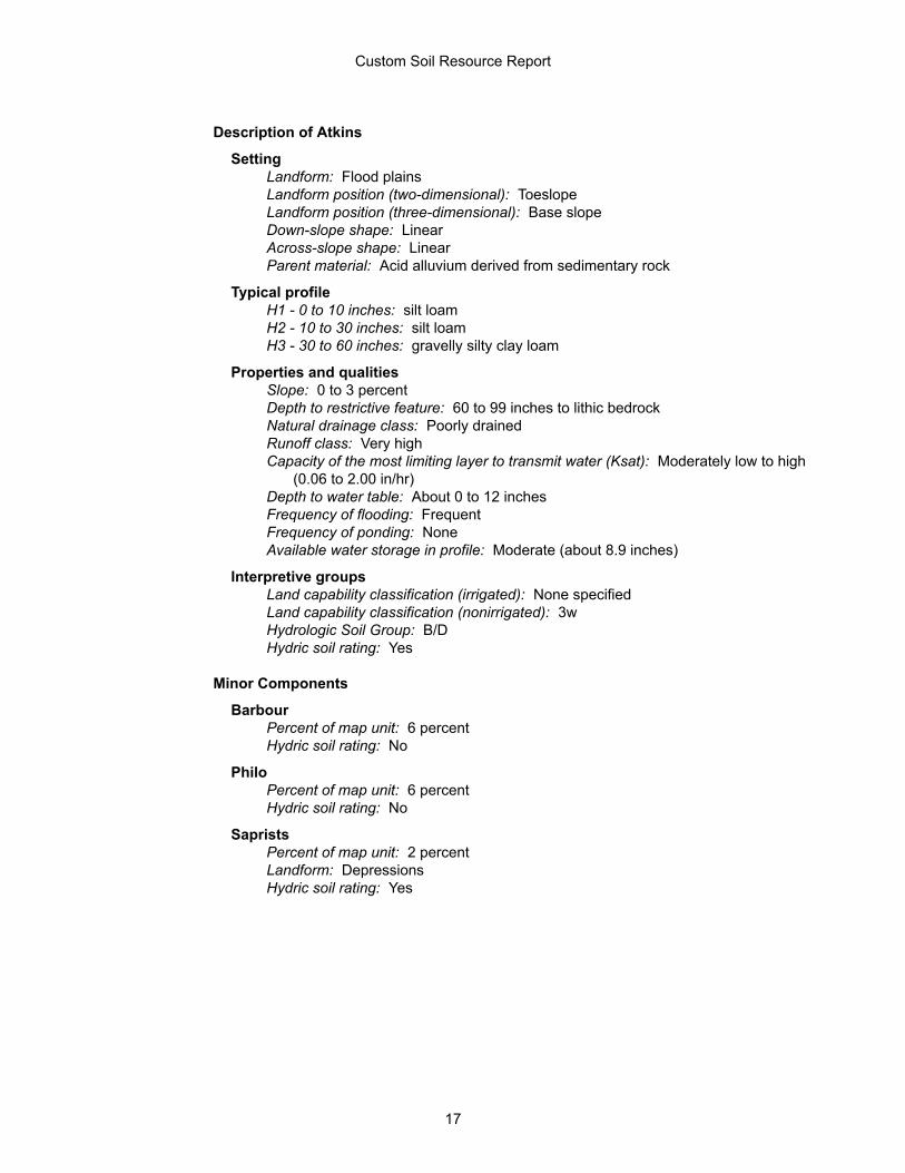
Description of Atkins
SettingLandform: Flood plainsLandform position (two-dimensional): ToeslopeLandform position (three-dimensional): Base slopeDown-slope shape: LinearAcross-slope shape: LinearParent material: Acid alluvium derived from sedimentary rock
Typical profileH1 - 0 to 10 inches: silt loamH2 - 10 to 30 inches: silt loamH3 - 30 to 60 inches: gravelly silty clay loam
Properties and qualitiesSlope: 0 to 3 percentDepth to restrictive feature: 60 to 99 inches to lithic bedrockNatural drainage class: Poorly drainedRunoff class: Very highCapacity of the most limiting layer to transmit water (Ksat): Moderately low to high
(0.06 to 2.00 in/hr)Depth to water table: About 0 to 12 inchesFrequency of flooding: FrequentFrequency of ponding: NoneAvailable water storage in profile: Moderate (about 8.9 inches)
Interpretive groupsLand capability classification (irrigated): None specifiedLand capability classification (nonirrigated): 3wHydrologic Soil Group: B/DHydric soil rating: Yes
Minor Components
BarbourPercent of map unit: 6 percentHydric soil rating: No
PhiloPercent of map unit: 6 percentHydric soil rating: No
SapristsPercent of map unit: 2 percentLandform: DepressionsHydric soil rating: Yes
Custom Soil Resource Report
17

BeC—Berks shaly silt loam, 8 to 15 percent slopes
Map Unit SettingNational map unit symbol: r926Elevation: 300 to 3,000 feetMean annual precipitation: 30 to 65 inchesMean annual air temperature: 46 to 59 degrees FFrost-free period: 120 to 214 daysFarmland classification: Farmland of statewide importance
Map Unit CompositionBerks and similar soils: 85 percentMinor components: 15 percentEstimates are based on observations, descriptions, and transects of the mapunit.
Description of Berks
SettingLandform: HillslopesLandform position (two-dimensional): ShoulderLandform position (three-dimensional): Side slopeDown-slope shape: Linear, convexAcross-slope shape: Convex, linearParent material: Acid silty residuum weathered from shale and siltstone
Typical profileH1 - 0 to 7 inches: channery silt loamH2 - 7 to 29 inches: very channery silt loamH3 - 29 to 34 inches: extremely channery silt loamH4 - 34 to 38 inches: bedrock
Properties and qualitiesSlope: 8 to 15 percentDepth to restrictive feature: 20 to 40 inches to lithic bedrockNatural drainage class: Well drainedRunoff class: LowCapacity of the most limiting layer to transmit water (Ksat): Moderately high to
high (0.60 to 6.00 in/hr)Depth to water table: More than 80 inchesFrequency of flooding: NoneFrequency of ponding: NoneAvailable water storage in profile: Very low (about 2.6 inches)
Interpretive groupsLand capability classification (irrigated): None specifiedLand capability classification (nonirrigated): 3eHydrologic Soil Group: BHydric soil rating: No
Custom Soil Resource Report
18

Minor Components
BedingtonPercent of map unit: 5 percentHydric soil rating: No
WeikertPercent of map unit: 4 percentHydric soil rating: No
BlairtonPercent of map unit: 3 percentHydric soil rating: No
ErnestPercent of map unit: 3 percentHydric soil rating: No
BhB—Berks stony silt loam, 3 to 8 percent slopes
Map Unit SettingNational map unit symbol: r928Elevation: 300 to 1,500 feetMean annual precipitation: 36 to 50 inchesMean annual air temperature: 52 to 55 degrees FFrost-free period: 170 to 214 daysFarmland classification: Not prime farmland
Map Unit CompositionBerks and similar soils: 100 percentEstimates are based on observations, descriptions, and transects of the mapunit.
Description of Berks
SettingLandform: HillslopesLandform position (two-dimensional): SummitLandform position (three-dimensional): InterfluveDown-slope shape: Linear, convexAcross-slope shape: Convex, linearParent material: Acid silty residuum weathered from shale and siltstone
Typical profileH1 - 0 to 7 inches: channery silt loamH2 - 7 to 29 inches: very channery silt loamH3 - 29 to 34 inches: extremely channery silt loamH4 - 34 to 38 inches: bedrock
Properties and qualitiesSlope: 3 to 8 percentDepth to restrictive feature: 20 to 40 inches to lithic bedrock
Custom Soil Resource Report
19

Natural drainage class: Well drainedRunoff class: LowCapacity of the most limiting layer to transmit water (Ksat): Moderately high to
high (0.60 to 6.00 in/hr)Depth to water table: More than 80 inchesFrequency of flooding: NoneFrequency of ponding: NoneAvailable water storage in profile: Very low (about 2.6 inches)
Interpretive groupsLand capability classification (irrigated): None specifiedLand capability classification (nonirrigated): 2eHydrologic Soil Group: BHydric soil rating: No
BhD—Berks stony silt loam, 8 to 25 percent slopes
Map Unit SettingNational map unit symbol: r929Elevation: 300 to 1,500 feetMean annual precipitation: 36 to 50 inchesMean annual air temperature: 52 to 55 degrees FFrost-free period: 170 to 214 daysFarmland classification: Not prime farmland
Map Unit CompositionBerks and similar soils: 100 percentEstimates are based on observations, descriptions, and transects of the mapunit.
Description of Berks
SettingLandform: HillslopesLandform position (two-dimensional): SummitLandform position (three-dimensional): InterfluveDown-slope shape: Linear, convexAcross-slope shape: Convex, linearParent material: Acid silty residuum weathered from shale and siltstone
Typical profileH1 - 0 to 7 inches: channery silt loamH2 - 7 to 29 inches: very channery silt loamH3 - 29 to 34 inches: extremely channery silt loamH4 - 34 to 38 inches: bedrock
Properties and qualitiesSlope: 8 to 25 percentDepth to restrictive feature: 20 to 40 inches to lithic bedrockNatural drainage class: Well drainedRunoff class: MediumCapacity of the most limiting layer to transmit water (Ksat): Moderately high to
high (0.60 to 6.00 in/hr)
Custom Soil Resource Report
20

Depth to water table: More than 80 inchesFrequency of flooding: NoneFrequency of ponding: NoneAvailable water storage in profile: Very low (about 2.6 inches)
Interpretive groupsLand capability classification (irrigated): None specifiedLand capability classification (nonirrigated): 6sHydrologic Soil Group: BHydric soil rating: No
BrA—Brinkerton silt loam, 0 to 3 percent slopes
Map Unit SettingNational map unit symbol: r92dElevation: 300 to 3,000 feetMean annual precipitation: 35 to 55 inchesMean annual air temperature: 46 to 59 degrees FFrost-free period: 120 to 217 daysFarmland classification: Not prime farmland
Map Unit CompositionBrinkerton and similar soils: 80 percentMinor components: 20 percentEstimates are based on observations, descriptions, and transects of the mapunit.
Description of Brinkerton
SettingLandform: DepressionsLandform position (two-dimensional): ToeslopeLandform position (three-dimensional): Base slopeDown-slope shape: ConcaveAcross-slope shape: ConcaveParent material: Local fine-silty colluvium derived from sedimentary rock
Typical profileH1 - 0 to 9 inches: silt loamH2 - 9 to 18 inches: silty clay loamH3 - 18 to 46 inches: silty clay loamH4 - 46 to 65 inches: channery silt loam
Properties and qualitiesSlope: 0 to 3 percentDepth to restrictive feature: 15 to 34 inches to fragipanNatural drainage class: Poorly drainedRunoff class: Very highCapacity of the most limiting layer to transmit water (Ksat): Moderately low to
moderately high (0.06 to 0.20 in/hr)Depth to water table: About 0 to 6 inchesFrequency of flooding: NoneFrequency of ponding: None
Custom Soil Resource Report
21

Available water storage in profile: Low (about 3.4 inches)
Interpretive groupsLand capability classification (irrigated): None specifiedLand capability classification (nonirrigated): 4wHydrologic Soil Group: DHydric soil rating: Yes
Minor Components
AtkinsPercent of map unit: 6 percentLandform: Flood plainsLandform position (three-dimensional): Base slopeDown-slope shape: ConcaveAcross-slope shape: ConcaveHydric soil rating: Yes
PhiloPercent of map unit: 5 percentHydric soil rating: No
LaidigPercent of map unit: 5 percentLandform: MountainsLandform position (two-dimensional): FootslopeLandform position (three-dimensional): Lower third of mountainflankDown-slope shape: ConcaveAcross-slope shape: ConcaveHydric soil rating: No
BerksPercent of map unit: 4 percentLandform: Ridges, valleysLandform position (two-dimensional): BackslopeLandform position (three-dimensional): Side slopeDown-slope shape: Convex, linearAcross-slope shape: Convex, linearHydric soil rating: No
BrB—Brinkerton silt loam, 3 to 8 percent slopes
Map Unit SettingNational map unit symbol: r92fElevation: 300 to 3,000 feetMean annual precipitation: 30 to 65 inchesMean annual air temperature: 46 to 59 degrees FFrost-free period: 120 to 217 daysFarmland classification: Not prime farmland
Custom Soil Resource Report
22

Map Unit CompositionBrinkerton and similar soils: 75 percentMinor components: 25 percentEstimates are based on observations, descriptions, and transects of the mapunit.
Description of Brinkerton
SettingLandform: DepressionsLandform position (two-dimensional): ToeslopeLandform position (three-dimensional): Base slopeDown-slope shape: ConcaveAcross-slope shape: ConcaveParent material: Local fine-silty colluvium derived from sedimentary rock
Typical profileH1 - 0 to 9 inches: silt loamH2 - 9 to 18 inches: silty clay loamH3 - 18 to 46 inches: silty clay loamH4 - 46 to 65 inches: channery silt loam
Properties and qualitiesSlope: 3 to 8 percentDepth to restrictive feature: 15 to 34 inches to fragipanNatural drainage class: Poorly drainedRunoff class: Very highCapacity of the most limiting layer to transmit water (Ksat): Moderately low to
moderately high (0.06 to 0.20 in/hr)Depth to water table: About 0 to 6 inchesFrequency of flooding: NoneFrequency of ponding: NoneAvailable water storage in profile: Low (about 3.4 inches)
Interpretive groupsLand capability classification (irrigated): None specifiedLand capability classification (nonirrigated): 4wHydrologic Soil Group: DHydric soil rating: Yes
Minor Components
ErnestPercent of map unit: 10 percentHydric soil rating: No
BerksPercent of map unit: 5 percentLandform: Ridges, valleysLandform position (two-dimensional): BackslopeLandform position (three-dimensional): Side slopeDown-slope shape: Convex, linearAcross-slope shape: Convex, linearHydric soil rating: No
LaidigPercent of map unit: 5 percentLandform: Mountains
Custom Soil Resource Report
23

Landform position (two-dimensional): FootslopeLandform position (three-dimensional): Lower third of mountainflankDown-slope shape: ConcaveAcross-slope shape: ConcaveHydric soil rating: No
AtkinsPercent of map unit: 3 percentLandform: Flood plainsDown-slope shape: ConcaveAcross-slope shape: ConcaveHydric soil rating: Yes
PhiloPercent of map unit: 2 percentHydric soil rating: No
HfF—Hazleton channery sandy loam, 25 to 60 percent slopes, rubbly
Map Unit SettingNational map unit symbol: 2wkd3Elevation: 330 to 2,230 feetMean annual precipitation: 37 to 50 inchesMean annual air temperature: 50 to 56 degrees FFrost-free period: 155 to 185 daysFarmland classification: Not prime farmland
Map Unit CompositionHazleton and similar soils: 85 percentMinor components: 15 percentEstimates are based on observations, descriptions, and transects of the mapunit.
Description of Hazleton
SettingLandform: RidgesLandform position (two-dimensional): BackslopeLandform position (three-dimensional): MountaintopDown-slope shape: ConvexAcross-slope shape: ConvexParent material: Residuum weathered from acid sandstone
Typical profileOi - 0 to 1 inches: slightly decomposed plant materialA - 1 to 6 inches: channery sandy loamE - 6 to 9 inches: channery sandy loamBs - 9 to 11 inches: channery sandy loamBw1 - 11 to 19 inches: channery sandy loamBw2 - 19 to 40 inches: very channery sandy loamC - 40 to 60 inches: very flaggy sandy loamR - 60 to 70 inches: bedrock
Custom Soil Resource Report
24

Properties and qualitiesSlope: 25 to 60 percentPercent of area covered with surface fragments: 18.0 percentDepth to restrictive feature: 40 to 69 inches to lithic bedrockNatural drainage class: Well drainedRunoff class: MediumCapacity of the most limiting layer to transmit water (Ksat): High (1.98 to 5.95
in/hr)Depth to water table: More than 80 inchesFrequency of flooding: NoneFrequency of ponding: NoneAvailable water storage in profile: Low (about 5.3 inches)
Interpretive groupsLand capability classification (irrigated): None specifiedLand capability classification (nonirrigated): 7sHydrologic Soil Group: AHydric soil rating: No
Minor Components
DekalbPercent of map unit: 10 percentLandform: Hillslopes, mountain slopesLandform position (two-dimensional): Summit, shoulder, backslopeLandform position (three-dimensional): Upper third of mountainflank, mountaintop,
side slope, interfluve, nose slopeDown-slope shape: ConvexAcross-slope shape: Convex, linearOther vegetative classification: Very Rocky, Acid Soils (RA3)Hydric soil rating: No
LehewPercent of map unit: 5 percentLandform: Hillslopes, mountain slopesLandform position (two-dimensional): Summit, shoulder, backslopeLandform position (three-dimensional): Upper third of mountainflank, mountaintop,
side slope, interfluve, nose slopeDown-slope shape: ConvexAcross-slope shape: Convex, linearHydric soil rating: No
MdD—Meckesville very stony silt loam, 8 to 25 percent slopes
Map Unit SettingNational map unit symbol: r950Elevation: 600 to 2,800 feetMean annual precipitation: 34 to 48 inchesMean annual air temperature: 46 to 55 degrees FFrost-free period: 130 to 210 days
Custom Soil Resource Report
25

Farmland classification: Not prime farmland
Map Unit CompositionMeckesville and similar soils: 90 percentMinor components: 5 percentEstimates are based on observations, descriptions, and transects of the mapunit.
Description of Meckesville
SettingLandform: Mountain slopesLandform position (two-dimensional): FootslopeLandform position (three-dimensional): Lower third of mountainflankDown-slope shape: ConcaveAcross-slope shape: LinearParent material: Sandstone, siltstone and shale colluvium derived from
sedimentary rock
Typical profileH1 - 0 to 7 inches: channery silt loamH2 - 7 to 31 inches: gravelly silty clay loamH3 - 31 to 60 inches: gravelly clay loamH4 - 60 to 64 inches: gravelly clay loam
Properties and qualitiesSlope: 15 to 25 percentPercent of area covered with surface fragments: 1.6 percentDepth to restrictive feature: 25 to 48 inches to fragipan; 72 to 99 inches to lithic
bedrockNatural drainage class: Well drainedRunoff class: HighCapacity of the most limiting layer to transmit water (Ksat): Moderately high (0.20
to 0.60 in/hr)Depth to water table: About 27 to 45 inchesFrequency of flooding: NoneFrequency of ponding: NoneAvailable water storage in profile: Low (about 3.9 inches)
Interpretive groupsLand capability classification (irrigated): None specifiedLand capability classification (nonirrigated): 6sHydrologic Soil Group: CHydric soil rating: No
Minor Components
AlbrightsPercent of map unit: 5 percentHydric soil rating: No
Custom Soil Resource Report
26

SrD—Sideling gravelly loam, 8 to 25 percent slopes, extremely stony
Map Unit SettingNational map unit symbol: rccgElevation: 500 to 2,400 feetMean annual precipitation: 34 to 50 inchesMean annual air temperature: 46 to 57 degrees FFrost-free period: 120 to 200 daysFarmland classification: Not prime farmland
Map Unit CompositionSideling and similar soils: 85 percentMinor components: 15 percentEstimates are based on observations, descriptions, and transects of the mapunit.
Description of Sideling
SettingLandform: Mountain slopesLandform position (two-dimensional): FootslopeLandform position (three-dimensional): Side slopeDown-slope shape: ConcaveAcross-slope shape: ConvexParent material: Fine-loamy colluvium derived from sedimentary rock
Typical profileH1 - 0 to 4 inches: gravelly loamH2 - 4 to 38 inches: gravelly clay loamH3 - 38 to 74 inches: channery silty clay loam
Properties and qualitiesSlope: 8 to 25 percentPercent of area covered with surface fragments: 9.0 percentDepth to restrictive feature: 60 to 80 inches to lithic bedrockNatural drainage class: Moderately well drainedRunoff class: HighCapacity of the most limiting layer to transmit water (Ksat): Moderately low to
moderately high (0.06 to 0.20 in/hr)Depth to water table: About 31 to 47 inchesFrequency of flooding: NoneFrequency of ponding: NoneAvailable water storage in profile: Moderate (about 7.4 inches)
Interpretive groupsLand capability classification (irrigated): None specifiedLand capability classification (nonirrigated): 7sHydrologic Soil Group: CHydric soil rating: No
Custom Soil Resource Report
27

Minor Components
WeikertPercent of map unit: 5 percentHydric soil rating: No
BuchananPercent of map unit: 5 percentHydric soil rating: No
Fluvaquentic dystrudeptsPercent of map unit: 5 percent
Custom Soil Resource Report
28

ReferencesAmerican Association of State Highway and Transportation Officials (AASHTO). 2004. Standard specifications for transportation materials and methods of sampling and testing. 24th edition.
American Society for Testing and Materials (ASTM). 2005. Standard classification of soils for engineering purposes. ASTM Standard D2487-00.
Cowardin, L.M., V. Carter, F.C. Golet, and E.T. LaRoe. 1979. Classification of wetlands and deep-water habitats of the United States. U.S. Fish and Wildlife Service FWS/OBS-79/31.
Federal Register. July 13, 1994. Changes in hydric soils of the United States.
Federal Register. September 18, 2002. Hydric soils of the United States.
Hurt, G.W., and L.M. Vasilas, editors. Version 6.0, 2006. Field indicators of hydric soils in the United States.
National Research Council. 1995. Wetlands: Characteristics and boundaries.
Soil Survey Division Staff. 1993. Soil survey manual. Soil Conservation Service. U.S. Department of Agriculture Handbook 18. http://www.nrcs.usda.gov/wps/portal/nrcs/detail/national/soils/?cid=nrcs142p2_054262
Soil Survey Staff. 1999. Soil taxonomy: A basic system of soil classification for making and interpreting soil surveys. 2nd edition. Natural Resources Conservation Service, U.S. Department of Agriculture Handbook 436. http://www.nrcs.usda.gov/wps/portal/nrcs/detail/national/soils/?cid=nrcs142p2_053577
Soil Survey Staff. 2010. Keys to soil taxonomy. 11th edition. U.S. Department of Agriculture, Natural Resources Conservation Service. http://www.nrcs.usda.gov/wps/portal/nrcs/detail/national/soils/?cid=nrcs142p2_053580
Tiner, R.W., Jr. 1985. Wetlands of Delaware. U.S. Fish and Wildlife Service and Delaware Department of Natural Resources and Environmental Control, Wetlands Section.
United States Army Corps of Engineers, Environmental Laboratory. 1987. Corps of Engineers wetlands delineation manual. Waterways Experiment Station Technical Report Y-87-1.
United States Department of Agriculture, Natural Resources Conservation Service. National forestry manual. http://www.nrcs.usda.gov/wps/portal/nrcs/detail/soils/home/?cid=nrcs142p2_053374
United States Department of Agriculture, Natural Resources Conservation Service. National range and pasture handbook. http://www.nrcs.usda.gov/wps/portal/nrcs/detail/national/landuse/rangepasture/?cid=stelprdb1043084
29

United States Department of Agriculture, Natural Resources Conservation Service. National soil survey handbook, title 430-VI. http://www.nrcs.usda.gov/wps/portal/nrcs/detail/soils/scientists/?cid=nrcs142p2_054242
United States Department of Agriculture, Natural Resources Conservation Service. 2006. Land resource regions and major land resource areas of the United States, the Caribbean, and the Pacific Basin. U.S. Department of Agriculture Handbook 296. http://www.nrcs.usda.gov/wps/portal/nrcs/detail/national/soils/?cid=nrcs142p2_053624
United States Department of Agriculture, Soil Conservation Service. 1961. Land capability classification. U.S. Department of Agriculture Handbook 210. http://www.nrcs.usda.gov/Internet/FSE_DOCUMENTS/nrcs142p2_052290.pdf
Custom Soil Resource Report
30

ATTACHMENT 3 450-FOOT WELL SURVEY

!H
#*
#*
PA-PE-0002.0000-RD
Well 2
WL-11062017-638-01
Well 1
York
Perry
Franklin
Centre
Blair
Huntingdon
AdamsFulto
n
Mifflin
Juniata
Bedf
ord
Snyder
Cumberland
Dauphin
P:\
GIS
\pro
jects
\11
2C
05
95
8-P
PP
\MX
D\W
ellL
oca
tio
ns\W
ellL
oca
tio
n_
PA
_P
E_
00
02
_0
00
0_
Kn
ow
nW
ells
.mxd
JL
E
Prepared By:
Coordinate System: NAD 83 Stateplane, PA South, Feet
Date:1/22/2018
Base Map;ESRI World Imagery, 09/24/2015
Well Location MapHDD# PA-PE-0002.0000-RD
Perry County, PA.
LegendLOD
Parcel
PPP Centerline
HDD
450 foot buffer of HDD
alignment
**Testing locations current asof 01/22/2018!H GES Testing Location
#* Known well >450' from HDDalignment
0 500250
Feet
Location
Age (years)
Depth(feet)
Flow (gallons/min
ute)Size
(inches)Well 1 737 812 60 150 20 6Well 2 1,000 1,074 30 150 20 8
Reported DTB (Feet)
Reported DTW (Feet)
WL-11062017-638-01 483 490 Unknown Unknown UnknownReported Pump Depth
Well InformationGES Testing Well
GES Well IDDistance to HDD
Perpindicular (Feet)
Distance to HDD Entry/Exit (Feet)
Well IDDistance to HDD
Perpindicular (feet)
Distance to HDD Entry/Exit (feet)
Well InformationKnown Wells >450' from HDD Alignment

HORSE VALLEY ROAD CROSSING PADEP SECTION 105 PERMIT NO. E50-258
PA-PE-0002.0000-RD & PA-PE-0002.0000-RD-16 (SPLP HDD No. S2-0157)
ATTACHMENT 2
PRODUCED WATER CONTAINMENT, CONTROL, AND FILTRATION


HORSE VALLEY ROAD CROSSING PADEP SECTION 105 PERMIT NO. E50-258
PA-PE-0002.0000-RD & PA-PE-0002.0000-RD-16 (SPLP HDD No. S2-0157)
ATTACHMENT 3
WATER SUPPLY ILLUSTRATION

!H
#*
#*
PA-PE-0002.0000-RD
Well 2
WL-11062017-638-01
Well 1
York
Perry
Franklin
Centre
Blair
Huntingdon
AdamsFulto
n
Mifflin
Juniata
Bedf
ord
Snyder
Cumberland
Dauphin
P:\
GIS
\pro
jects
\11
2C
05
95
8-P
PP
\MX
D\W
ellL
oca
tio
ns\W
ellL
oca
tio
n_
PA
_P
E_
00
02
_0
00
0_
Kn
ow
nW
ells
.mxd
JL
E
Prepared By:
Coordinate System: NAD 83 Stateplane, PA South, Feet
Date:1/22/2018
Base Map;ESRI World Imagery, 09/24/2015
Well Location MapHDD# PA-PE-0002.0000-RD
Perry County, PA.
LegendLOD
Parcel
PPP Centerline
HDD
450 foot buffer of HDD
alignment
**Testing locations current asof 01/22/2018!H GES Testing Location
#* Known well >450' from HDDalignment
0 500250
Feet
Location
Age (years)
Depth(feet)
Flow (gallons/min
ute)Size
(inches)Well 1 737 812 60 150 20 6Well 2 1,000 1,074 30 150 20 8
Reported DTB (Feet)
Reported DTW (Feet)
WL-11062017-638-01 483 490 Unknown Unknown UnknownReported Pump Depth
Well InformationGES Testing Well
GES Well IDDistance to HDD
Perpindicular (Feet)
Distance to HDD Entry/Exit (Feet)
Well IDDistance to HDD
Perpindicular (feet)
Distance to HDD Entry/Exit (feet)
Well InformationKnown Wells >450' from HDD Alignment
HORSE VALLEY ROAD CROSSING PADEP SECTION 105 PERMIT NO. E50-258
PA-PE-0002.0000-RD & PA-PE-0002.0000-RD-16 (SPLP HDD No. S2-0157)
ATTACHMENT 4
ORIGINAL AND REVISED HORIZONTAL DIRECTIONAL DRILL PLAN AND PROFILES

HORSE VALLEY RDN40.293755W77.654167
GAS GAS GAS GAS GAS GAS GAS GAS GAS GAS GAS GAS GAS GAS GAS GAS GAS GAS GAS GAS GAS GAS GAS GAS GAS GAS GAS GAS GAS GAS GAS GAS GAS GAS GAS GAS GAS GAS GAS GAS GAS
0+00
1+00
2+00
3+00
4+00
5+00
6+00
7+00
8+00
9+00
10+0
0
11+0
0
12+0
0
13+0
0
14+0
0
15+0
0
15+5
7
HDD EXIT/ENTRYN40.293822W77.654496
HDD ENTRY/EXITN40.292723W77.649103
GEOTECH SB-01
GEOTECH SB-02
900
1000
1100
1200
900
1000
1100
1200
-1+000+001+002+003+004+005+006+007+008+009+0010+0011+0012+0013+0014+0015+0016+0017+00
STR
EAM
S-Q
693+
77
HD
D E
XIT/
ENTR
Y15
+57
EL.1
140'
HD
D E
NTR
Y/EX
IT0+
00EL
.107
5'
STA. 14+88EL. 1121'
STA. 9+37EL. 1044'
STA. 3+66EL. 1044'
23'
571'
71'
16°
OVE
RH
EAD
ELE
CTR
IC14
+17
OVE
RH
EAD
ELE
CTR
IC13
+61
14'
8°
R=2000'L=551'S=559'
89'R=2000'L=278'S=279'
GEO
TEC
H S
B-02
7+64
, 38'
LT
GEO
TEC
H S
B-01
14+4
9, 1
59' L
T
HO
RSE
VAL
LEY
RD
14+6
2
APPROXIMATE BEDROCK
STA. 0+88EL. 1063'
APPROXIMATE BEDROCK
LEGENDPERMANENT ROWTEMPORARY CONSTRUCTION ROWTEMPORARY WORKSPACETEMPORARY ACCESS ROADPERMANENT ACCESS ROADSPOIL SPACE ONLYPROPOSED HDDPROPOSED 20" PIPELINEPROPOSED 16" PIPELINEHDD ENTRY-EXIT
PEM WETLANDSPSS WETLANDSPFO WETLANDSPLAN VIEW
PROFILE VIEW
NO. DESCRIPTION DATEBY CHK DATE
REVISIONS
DATEAPP
NOTES Sunoco LogisticsPartners L.P.
HORIZONTAL DIRECTIONAL DRILL
SUNOCO PIPELINE, L.P.1. ALL COORDINATES SHOWN ARE IN LATITUDE AND LONGITUDE. ALL MSL ELEVATIONS ARE NAD832. STATIONING IS BASED ON HORIZONTAL DISTANCES.3. ROONEY ENGINEERING, INC. AND SUNOCO PIPELINE, LP ARE NOT RESPONSIBLE FOR LOCATION OF FOREIGN UTILITIES SHOWN IN PLOT PLAN OR PROFILE. THE INFORMATION SHOWN HEREON IS FURNISHED WITHOUT LIABILITY ON THE PART OF ROONEY ENGINEERING, INC. AND SUNOCO PIPELINE, LP, FOR ANY DAMAGES RESULTING FROM ERRORS OR OMISSIONS THEREIN.4. CONTRACTOR IS RESPONSIBLE FOR LOCATING ALL UTILITIES. CONTACT ONE CALL AT 811 PRIOR TO DIGGING.5. SUNOCO EMERGENCY HOTLINE NUMBER IS #1-800-786-7440.
PENNSYLVANIA PIPELINE PROJECT
DESIGN AND CONSTRUCTION:1. CONTRACTOR SHALL FIELD VERIFY DEPTH OF ALL EXISTING UTILITIES SHOWN OR NOT SHOWN ON
THIS DRAWING.2. THE MINIMUM SEPARATION DISTANCE FROM EXISTING SUBSURFACE UTILITIES SHALL NOT BE LESS
THAN 10 FEET AS MEASURED FROM THE OUTSIDE EDGE OF THE UTILITY TO OUTSIDE OF PROPOSEDPIPELINE.
3. DESIGNED IN ACCORDANCE WITH CFR 49 195 & ASME B31.44. CROSSING PIPE SPECIFICATION: HDD HORZ. LENGTH (L=): HDD PIPE LENGTH (S=): 20" x 0.456" W.T., X-65, API5L, PSL2, ERW, BFW COATING: 14-16 MILS FBE WITH 30-35 MIL ARO (POWERCRETE OR ENGINEER APPROVED EQUAL)
5. INTERNAL DESIGN PRESSURE 1480 PSIG (SEAM FACTOR 1.0, DESIGH FACTOR 0.50).6. INSTALLATION METHOD: HORIZONTAL DIRECTIONAL DRILL (HDD).7. PIPELINE WARNING MARKERS SHALL BE INSTALLED ON BOTH SIDES OF ALL ROAD, RAILWAY, AND
STREAM CROSSINGS.8. CARRIER PIPE NOT ENCASED.9. PIPE / AMBIENT TEMPERATURE MUST BE NO LESS THAN 30°F DURING PULLBACK WITHOUT PRIOR
WRITTEN APPROVAL FROM THE ENGINEER.10. CONDUCT 4-HOUR PRE-INSTALLATION HYDROTEST OF HDD PIPE STRING TO MINIMUM 1850 PSIG.11. SEE SUNOCO PENNSYLVANIA PIPELINE PROJECT ESRI WEBMAP FOR ACCESS ROAD ALIGNMENT.
12. SUNOCO PIPELINE, L.P.'S HORIZONTAL DIRECTIONAL DRILL INADVERTENT RETURN CONTINGENCY PLANWILL BE IMPLEMENTED AT ALL TIMES.
13. SUNOCO PIPELINE, L.P.'S EROSION AND SEDIMENTATION CONTROL PLAN WILL BE IMPLEMENTED AT ALLTIMES.
HORSE VALLEY ROAD
1"=150' PA-PE-0002.0000-RD
PERRY COUNTY PENNSYLVANIA, TOBOYNE TOWNSHIPS2-0157
0 ISSUED FOR CONSTRUCTION MRS RMB AAW12/22/15 12/22/1512/22/15
2 REVISED PROFILE WITH 2017 LIDAR MRS RMB CAG03/22/17 03/22/17 03/22/17
1 REVISED PER ENGINEERING COMMENTS DLM RMB AAW08/26/16 08/26/16 08/26/16
1557'1569'
0
FEET
75 75 150
GRADE
PA-PE-0002.0000
PA-PE-0005.0000
PA-PE-0002.0000
PA-PE-0004.0000
PULLBACK ALONG ROW
HO
RSE
VAL
LEY
RO
AD
PROPOSED 20" PIPELINE
EXISTING 8" SUNOCO PIPELINE
PROPOSED 16" PIPELINE
-CL (0.1' - 13.5')
-NG EL. 1126'
GEOTECH SB-01
-TOPSOIL (0' - 0.1')
-COMPLETION DEPTH EL. 1106'
-SHALE (18.5' - 20.3')
-SC (13.5' - 18.5')-GROUNDWATER (17.5')
-SM (0.2' - 3.5')
-NG EL. 1079'
GEOTECH SB-02
-TOPSOIL (0' - 0.2')
-COMPLETION DEPTH EL. 1063'
-SHALE (15.0' - 15.9')-SC (3.5' - 15.0')-GROUNDWATER (8.0')
NOTE: REFER TO TEST BORING LOG S2-0157FOR COMPLETE SOIL MATERIAL DESCRIPTION
SUNOCO EASEMENTLIMITS - NOT LOD

GASGAS GAS
GASGAS GAS GAS
GAS GASGAS GAS GAS GAS
GAS
GAS GAS GAS GASGAS
GAS GAS GAS GASGAS GAS GAS
GAS GAS GASGAS GAS GAS GAS GAS GAS GAS GAS GAS GAS GAS GAS
GAS
GEOTECH SB-01
0+
00
1+
00
2+
00
3+
00
4+
00
5+
00
6+
00
7+
00
8+
00
9+
00
10+
00
11+
00
12+
00
13+
00
14+
00
15+
00
16+
00
17+
00
18+
00
19+
00
20+
00
21+
00
21+
25
GEOTECH SB-02
GEOTECH B3-5W
GEOTECH B3-5E
HDD ENTRY
N40.292564
W77.648049
HDD EXIT
N40.294065
W77.655410
900
1000
1100
1200
900
1000
1100
1200
-1+000+001+002+003+004+005+006+007+008+009+0010+0011+0012+0013+0014+0015+0016+0017+0018+0019+0020+0021+0022+00
CL S
TR
EA
M S
-Q
69
6+
88
HD
D E
XIT
21+
25
EL.1175'
HD
D E
NT
RY
0+
00
EL.1093'
STA. 18+61
EL. 1089'
STA. 12+43
EL. 991'
STA. 6+90
EL. 991'
554'
277'
OV
ER
HE
AD
E
LE
CT
RIC
17+
09
OV
ER
HE
AD
E
LE
CT
RIC
16+
54
70'
280'
12°
76'
STA. 2+74
EL. 1035'
18°
GE
OT
EC
H S
B-02
10+
63, 56' LT
GE
OT
EC
H S
B-01
17+
48, 177' LT
APPROXIMATE BEDROCK
APPROXIMATE
BEDROCK
HO
RS
E V
ALLE
Y R
D
17+
53
60'
R=2000'
L=618'
S=628'
R=2000'
L=416'
S=419'
ED
GE
O
F W
ET
LA
ND
L2
16+
76
ED
GE
O
F W
ET
LA
ND
L2
16+
65
ED
GE
O
F W
ET
LA
ND
L2
15+
05
ED
GE
O
F W
ET
LA
ND
L2
14+
23
ED
GE
O
F W
ET
LA
ND
L2
17+
17
ED
GE
O
F W
ET
LA
ND
L1
6+
27
ED
GE
O
F W
ET
LA
ND
L2
7+
24
ED
GE
O
F W
ET
LA
ND
L1
4+
11
LEGEND
PERMANENT ROW
TEMPORARY CONSTRUCTION ROW
TEMPORARY WORKSPACE
TEMPORARY ACCESS ROAD
PERMANENT ACCESS ROAD
SPOIL SPACE ONLY
PROPOSED HDD
PROPOSED 20" PIPELINE
PROPOSED 16" PIPELINE
HDD ENTRY-EXIT
PEM WETLANDS
PSS WETLANDS
PFO WETLANDS
PLAN VIEW
PROFILE VIEW
Sunoco LogisticsPartners L.P.
HORIZONTAL DIRECTIONAL DRILL
SUNOCO PIPELINE, L.P.
PENNSYLVANIA PIPELINE PROJECT
DESIGN AND CONSTRUCTION:
1. CONTRACTOR SHALL FIELD VERIFY DEPTH OF ALL EXISTING UTILITIES SHOWN OR NOT SHOWN ON
THIS DRAWING.
2. THE MINIMUM SEPARATION DISTANCE FROM EXISTING SUBSURFACE UTILITIES SHALL NOT BE LESS
THAN 10 FEET AS MEASURED FROM THE OUTSIDE EDGE OF THE UTILITY TO OUTSIDE OF PROPOSED
PIPELINE.
3. DESIGNED IN ACCORDANCE WITH CFR 49 195 & ASME B31.4
4. CROSSING PIPE SPECIFICATION:
HDD HORZ. LENGTH (L=):
HDD PIPE LENGTH (S=):
16" x 0.438" W.T., X-70, API5L, PSL2, ERW, BFW
COATING: 14-16 MILS FBE WITH 30-35 MIL ARO (POWERCRETE OR ENGINEER APPROVED EQUAL)
5. INTERNAL DESIGN PRESSURE 1480 PSIG (SEAM FACTOR 1.0, DESIGH FACTOR 0.50).
6. INSTALLATION METHOD: HORIZONTAL DIRECTIONAL DRILL (HDD).
7. PIPELINE WARNING MARKERS SHALL BE INSTALLED ON BOTH SIDES OF ALL ROAD, RAILWAY, AND
STREAM CROSSINGS.
8. CARRIER PIPE NOT ENCASED.
9. PIPE / AMBIENT TEMPERATURE MUST BE NO LESS THAN 30°F DURING PULLBACK WITHOUT PRIOR
WRITTEN APPROVAL FROM THE ENGINEER.
10. CONDUCT 4-HOUR PRE-INSTALLATION HYDROTEST OF HDD PIPE STRING TO MINIMUM 1850 PSIG.
11. SEE SUNOCO PENNSYLVANIA PIPELINE PROJECT ESRI WEBMAP FOR ACCESS ROAD ALIGNMENT.
12. SUNOCO PIPELINE, L.P.'S HORIZONTAL DIRECTIONAL DRILL INADVERTENT RETURN CONTINGENCY PLAN
WILL BE IMPLEMENTED AT ALL TIMES.
13. SUNOCO PIPELINE, L.P.'S EROSION AND SEDIMENTATION CONTROL PLAN WILL BE IMPLEMENTED AT ALL
TIMES.
0
FEET
100100 200
GRADE
PA-PE-0002.0000
PA-PE-0005.0000
PA-PE-0002.0000
PA-PE-0004.0000
PULLBACK ALONG ROW
H
O
R
S
E
V
A
L
L
E
Y
R
O
A
D
PROPOSED 20" PIPELINE
EXISTING 8" SUNOCO PIPELINE
PROPOSED 16" PIPELINE
-CL (0.1' - 13.5')
-NG EL. 1126'
GEOTECH SB-01
-TOPSOIL (0' - 0.1')
-COMPLETION
DEPTH EL. 1106'
-SHALE (18.5' - 20.3')
-SC (13.5' - 18.5')
-GROUNDWATER (17.5')
-SM (0.2' - 3.5')
-NG EL. 1079'
GEOTECH SB-02
-TOPSOIL (0' - 0.2')
-COMPLETION
DEPTH EL. 1063'
-SHALE (15.0' - 15.9')
-SC (3.5' - 15.0')
-GROUNDWATER (8.0')
NOTE: REFER TO TEST BORING LOG S2-0157
FOR COMPLETE SOIL MATERIAL DESCRIPTION
SUNOCO EASEMENT
LIMITS - NOT LOD
GEOTECH B3-5W
-NG EL. 1140'
NOTE: REFER TO TEST BORING LOG B3-5W TERRACON
PROJECT #J217P078 FOR COMPLETE SOIL MATERIAL
DESCRIPTION
-BORING TERMINATED EL. 1005'
-LEAN CLAY W/ GRAVEL CL
(0.0' - 29.0')
-WEATHERED ROCK/SHALE
(29.0' - 135.0')
GEOTECH B3-5E
-NG EL. 1175'
NOTE: REFER TO TEST BORING LOG B3-5E TERRACON
PROJECT #J217P078 FOR COMPLETE SOIL MATERIAL
DESCRIPTION
-BORING TERMINATED EL. 1090'
-LEAN CLAY CL
(0.0' - 13.0')
-WEATHERED ROCK/SHALE
(13.0' - 85.0')
-GROUNDWATER (20.0')
HORSE VALLEY ROAD
1"=200'
PA-PE-0002.0000-RD-16
PERRY COUNTY PENNSYLVANIA, TOBOYNE TOWNSHIP
S2-0157-16
MOVED DRILL ENTRY/EXIT LOCATION - DESIGN PER MICHELSMRS RMB CAG11/27/17 11/27/17 11/27/17
2125'
2158'
REF. DRAWING
EROSION & SEDIMENT PLAN
AERIAL SITE PLAN
NO. DESCRIPTION DATEBY CHK DATE
REVISIONS
DATEAPP
NOTES
1. ALL COORDINATES SHOWN ARE IN LATITUDE AND LONGITUDE. ALL MSL ELEVATIONS ARE NAD83
2. STATIONING IS BASED ON HORIZONTAL DISTANCES.
3. ROONEY ENGINEERING, INC. AND SUNOCO PIPELINE, LP ARE NOT RESPONSIBLE FOR LOCATION
OF FOREIGN UTILITIES SHOWN IN PLOT PLAN OR PROFILE. THE INFORMATION SHOWN HEREON IS
FURNISHED WITHOUT LIABILITY ON THE PART OF ROONEY ENGINEERING, INC. AND SUNOCO PIPELINE,
LP, FOR ANY DAMAGES RESULTING FROM ERRORS OR OMISSIONS THEREIN.
4. CONTRACTOR IS RESPONSIBLE FOR LOCATING ALL UTILITIES. CONTACT ONE CALL AT 811 PRIOR TO
DIGGING.
5. SUNOCO EMERGENCY HOTLINE NUMBER IS #1-800-786-7440.
TO
TO
DWG NO DWG NO DESCRIPTION
05/20/16
10/07/16
02/26/16
EP2 REVISED PER PADEP COMMENTS RECEIVED 09-06-16DLM RMB AAW10/07/16
ES-3.03
10/07/16
EP1 REVISED PER PADEP COMMENTSJTW RMB AAW05/20/16
SHEET 2
05/20/16
EP MRS RMB AAW02/26/16
ES-3.03
02/26/16
SHEET 2
EP3
REVERSED DRILL ENTRY/EXIT LOCATION - DESIGN PER MICHELSMRS RMB CAG01/03/18
EP401/03/18 01/03/18
UPDATED LOCATION OF ATWS BOXESMRS RMB CAG01/05/18
EP501/05/18 01/05/18

GAS GAS GAS GAS GAS GAS GAS GAS GAS GAS GAS GAS GAS GAS GAS GAS GAS GAS GAS GAS GAS GAS GAS GAS GAS GAS GAS GAS GAS GAS GAS GAS GAS GAS GAS GAS GAS GAS GAS GAS GAS GAS
GEOTECH SB-01
0+00
1+00
2+00
3+00
4+00
5+00
6+00
7+00
8+00
9+00
10+0
0
11+0
0
12+0
0
13+0
0
14+0
0
15+0
0
15+9
7
HDD ENTRY/EXITN40.292761W77.649015
HDD EXIT/ENTRYN40.293889W77.654548
GEOTECH SB-02
900
1000
1100
1200
900
1000
1100
1200
-1+000+001+002+003+004+005+006+007+008+009+0010+0011+0012+0013+0014+0015+0016+0017+00
STR
EAM
S-Q
694+
09
HD
D E
XIT/
ENTR
Y15
+97
EL.1
144'
HD
D E
NTR
Y/EX
IT0+
00EL
.107
5'
STA. 14+59EL. 1106'
STA. 10+18EL. 1044'
STA. 3+42EL. 1044'
676'
143'
OVE
RH
EAD
ELE
CTR
IC14
+30
OVE
RH
EAD
ELE
CTR
IC13
+75
17'
121'
8°24'
STA. 1+20EL. 1059'
R=1600'L=223'S=223'
16°
R=1600'L=441'S=447'
GEO
TEC
H S
B-02
7+84
, 56'
LT
HO
RSE
VAL
LEY
RD
14+7
4
APPROXIMATE BEDROCK
APPROXIMATEBEDROCK
LEGENDPERMANENT ROWTEMPORARY CONSTRUCTION ROWTEMPORARY WORKSPACETEMPORARY ACCESS ROADPERMANENT ACCESS ROADSPOIL SPACE ONLYPROPOSED HDDPROPOSED 20" PIPELINEPROPOSED 16" PIPELINEHDD ENTRY-EXIT
PEM WETLANDSPSS WETLANDSPFO WETLANDSPLAN VIEW
PROFILE VIEW
NO. DESCRIPTION DATEBY CHK DATE
REVISIONS
DATEAPP
NOTES Sunoco LogisticsPartners L.P.
HORIZONTAL DIRECTIONAL DRILL
SUNOCO PIPELINE, L.P.1. ALL COORDINATES SHOWN ARE IN LATITUDE AND LONGITUDE. ALL MSL ELEVATIONS ARE NAD832. STATIONING IS BASED ON HORIZONTAL DISTANCES.3. ROONEY ENGINEERING, INC. AND SUNOCO PIPELINE, LP ARE NOT RESPONSIBLE FOR LOCATION OF FOREIGN UTILITIES SHOWN IN PLOT PLAN OR PROFILE. THE INFORMATION SHOWN HEREON IS FURNISHED WITHOUT LIABILITY ON THE PART OF ROONEY ENGINEERING, INC. AND SUNOCO PIPELINE, LP, FOR ANY DAMAGES RESULTING FROM ERRORS OR OMISSIONS THEREIN.4. CONTRACTOR IS RESPONSIBLE FOR LOCATING ALL UTILITIES. CONTACT ONE CALL AT 811 PRIOR TO DIGGING.5. SUNOCO EMERGENCY HOTLINE NUMBER IS #1-800-786-7440.
PENNSYLVANIA PIPELINE PROJECT
DESIGN AND CONSTRUCTION:1. CONTRACTOR SHALL FIELD VERIFY DEPTH OF ALL EXISTING UTILITIES SHOWN OR NOT SHOWN ON
THIS DRAWING.2. THE MINIMUM SEPARATION DISTANCE FROM EXISTING SUBSURFACE UTILITIES SHALL NOT BE LESS
THAN 10 FEET AS MEASURED FROM THE OUTSIDE EDGE OF THE UTILITY TO OUTSIDE OF PROPOSEDPIPELINE.
3. DESIGNED IN ACCORDANCE WITH CFR 49 195 & ASME B31.44. CROSSING PIPE SPECIFICATION: HDD HORZ. LENGTH (L=): HDD PIPE LENGTH (S=): 16" x 0.438" W.T., X-70, API5L, PSL2, ERW, BFW COATING: 14-16 MILS FBE WITH 30-35 MIL ARO (POWERCRETE OR ENGINEER APPROVED EQUAL)
5. INTERNAL DESIGN PRESSURE 1480 PSIG (SEAM FACTOR 1.0, DESIGH FACTOR 0.50).6. INSTALLATION METHOD: HORIZONTAL DIRECTIONAL DRILL (HDD).7. PIPELINE WARNING MARKERS SHALL BE INSTALLED ON BOTH SIDES OF ALL ROAD, RAILWAY, AND
STREAM CROSSINGS.8. CARRIER PIPE NOT ENCASED.9. PIPE / AMBIENT TEMPERATURE MUST BE NO LESS THAN 30°F DURING PULLBACK WITHOUT PRIOR
WRITTEN APPROVAL FROM THE ENGINEER.10. CONDUCT 4-HOUR PRE-INSTALLATION HYDROTEST OF HDD PIPE STRING TO MINIMUM 1850 PSIG.11. SEE SUNOCO PENNSYLVANIA PIPELINE PROJECT ESRI WEBMAP FOR ACCESS ROAD ALIGNMENT.
12. SUNOCO PIPELINE, L.P.'S HORIZONTAL DIRECTIONAL DRILL INADVERTENT RETURN CONTINGENCY PLANWILL BE IMPLEMENTED AT ALL TIMES.
13. SUNOCO PIPELINE, L.P.'S EROSION AND SEDIMENTATION CONTROL PLAN WILL BE IMPLEMENTED AT ALLTIMES.
HORSE VALLEY ROAD
1"=150' PA-PE-0002.0000-RD-16
PERRY COUNTY PENNSYLVANIA, TOBOYNE TOWNSHIPS2-0157-16
0 ISSUED FOR CONSTRUCTION MRS RMB AAW12/22/15 12/22/1512/22/15
2 REVISED PROFILE WITH 2017 LIDAR MRS RMB CAG03/22/17 03/22/17 03/22/17
1 REVISED PER ENGINEERING COMMENTS DLM RMB AAW08/26/16 08/26/16 08/26/16
1597'1610'
0
FEET
75 75 150
GRADE
PA-PE-0004.0000
PA-PE-0002.0000
PA-PE-0005.0000
PA-PE-0002.0000
PULLBACK ALONG ROW
HO
RSE
VAL
LEY
RO
AD
PROPOSED 20" PIPELINE
EXISTING 8" SUNOCO PIPELINE
PROPOSED 16" PIPELINE
-CL (0.1' - 13.5')
-NG EL. 1126'
GEOTECH SB-01
-TOPSOIL (0' - 0.1')
-COMPLETION DEPTH EL. 1106'
-SHALE (18.5' - 20.3')
-SC (13.5' - 18.5')-GROUNDWATER (17.5')
-SM (0.2' - 3.5')
-NG EL. 1079'
GEOTECH SB-02
-TOPSOIL (0' - 0.2')
-COMPLETION DEPTH EL. 1063'
-SHALE (15.0' - 15.9')-SC (3.5' - 15.0')-GROUNDWATER (8.0')
NOTE: REFER TO TEST BORING LOG S2-0157FOR COMPLETE SOIL MATERIAL DESCRIPTION
SUNOCO EASEMENTLIMITS - NOT LOD

GASGAS GAS
GASGAS GAS GAS
GAS GASGAS GAS GAS GAS
GAS
GAS GAS GAS GASGAS
GAS GAS GAS GASGAS GAS GAS
GAS GAS GASGAS GAS GAS GAS GAS GAS GAS GAS GAS GAS GAS GAS
GAS
GEOTECH SB-01
0+
00
1+
00
2+
00
3+
00
4+
00
5+
00
6+
00
7+
00
8+
00
9+
00
10+
00
11+
00
12+
00
13+
00
14+
00
15+
00
16+
00
17+
00
18+
00
19+
00
20+
00
21+
00
21+
25
GEOTECH SB-02
GEOTECH B3-5W
GEOTECH B3-5E
HDD ENTRY
N40.292564
W77.648049
HDD EXIT
N40.294065
W77.655410
900
1000
1100
1200
900
1000
1100
1200
-1+000+001+002+003+004+005+006+007+008+009+0010+0011+0012+0013+0014+0015+0016+0017+0018+0019+0020+0021+0022+00
CL S
TR
EA
M S
-Q
69
6+
88
HD
D E
XIT
21+
25
EL.1175'
HD
D E
NT
RY
0+
00
EL.1093'
STA. 18+61
EL. 1089'
STA. 12+43
EL. 991'
STA. 6+90
EL. 991'
554'
277'
OV
ER
HE
AD
E
LE
CT
RIC
17+
09
OV
ER
HE
AD
E
LE
CT
RIC
16+
54
70'
280'
12°
76'
STA. 2+74
EL. 1035'
18°
GE
OT
EC
H S
B-02
10+
63, 56' LT
GE
OT
EC
H S
B-01
17+
48, 177' LT
APPROXIMATE BEDROCK
APPROXIMATE
BEDROCK
HO
RS
E V
ALLE
Y R
D
17+
53
60'
R=2000'
L=618'
S=628'
R=2000'
L=416'
S=419'
ED
GE
O
F W
ET
LA
ND
L2
16+
76
ED
GE
O
F W
ET
LA
ND
L2
16+
65
ED
GE
O
F W
ET
LA
ND
L2
15+
05
ED
GE
O
F W
ET
LA
ND
L2
14+
23
ED
GE
O
F W
ET
LA
ND
L2
17+
17
ED
GE
O
F W
ET
LA
ND
L1
6+
27
ED
GE
O
F W
ET
LA
ND
L2
7+
24
ED
GE
O
F W
ET
LA
ND
L1
4+
11
LEGEND
PERMANENT ROW
TEMPORARY CONSTRUCTION ROW
TEMPORARY WORKSPACE
TEMPORARY ACCESS ROAD
PERMANENT ACCESS ROAD
SPOIL SPACE ONLY
PROPOSED HDD
PROPOSED 20" PIPELINE
PROPOSED 16" PIPELINE
HDD ENTRY-EXIT
PEM WETLANDS
PSS WETLANDS
PFO WETLANDS
PLAN VIEW
PROFILE VIEW
Sunoco LogisticsPartners L.P.
HORIZONTAL DIRECTIONAL DRILL
SUNOCO PIPELINE, L.P.
PENNSYLVANIA PIPELINE PROJECT
DESIGN AND CONSTRUCTION:
1. CONTRACTOR SHALL FIELD VERIFY DEPTH OF ALL EXISTING UTILITIES SHOWN OR NOT SHOWN ON
THIS DRAWING.
2. THE MINIMUM SEPARATION DISTANCE FROM EXISTING SUBSURFACE UTILITIES SHALL NOT BE LESS
THAN 10 FEET AS MEASURED FROM THE OUTSIDE EDGE OF THE UTILITY TO OUTSIDE OF PROPOSED
PIPELINE.
3. DESIGNED IN ACCORDANCE WITH CFR 49 195 & ASME B31.4
4. CROSSING PIPE SPECIFICATION:
HDD HORZ. LENGTH (L=):
HDD PIPE LENGTH (S=):
16" x 0.438" W.T., X-70, API5L, PSL2, ERW, BFW
COATING: 14-16 MILS FBE WITH 30-35 MIL ARO (POWERCRETE OR ENGINEER APPROVED EQUAL)
5. INTERNAL DESIGN PRESSURE 1480 PSIG (SEAM FACTOR 1.0, DESIGH FACTOR 0.50).
6. INSTALLATION METHOD: HORIZONTAL DIRECTIONAL DRILL (HDD).
7. PIPELINE WARNING MARKERS SHALL BE INSTALLED ON BOTH SIDES OF ALL ROAD, RAILWAY, AND
STREAM CROSSINGS.
8. CARRIER PIPE NOT ENCASED.
9. PIPE / AMBIENT TEMPERATURE MUST BE NO LESS THAN 30°F DURING PULLBACK WITHOUT PRIOR
WRITTEN APPROVAL FROM THE ENGINEER.
10. CONDUCT 4-HOUR PRE-INSTALLATION HYDROTEST OF HDD PIPE STRING TO MINIMUM 1850 PSIG.
11. SEE SUNOCO PENNSYLVANIA PIPELINE PROJECT ESRI WEBMAP FOR ACCESS ROAD ALIGNMENT.
12. SUNOCO PIPELINE, L.P.'S HORIZONTAL DIRECTIONAL DRILL INADVERTENT RETURN CONTINGENCY PLAN
WILL BE IMPLEMENTED AT ALL TIMES.
13. SUNOCO PIPELINE, L.P.'S EROSION AND SEDIMENTATION CONTROL PLAN WILL BE IMPLEMENTED AT ALL
TIMES.
0
FEET
100100 200
GRADE
PA-PE-0002.0000
PA-PE-0005.0000
PA-PE-0002.0000
PA-PE-0004.0000
PULLBACK ALONG ROW
H
O
R
S
E
V
A
L
L
E
Y
R
O
A
D
PROPOSED 20" PIPELINE
EXISTING 8" SUNOCO PIPELINE
PROPOSED 16" PIPELINE
-CL (0.1' - 13.5')
-NG EL. 1126'
GEOTECH SB-01
-TOPSOIL (0' - 0.1')
-COMPLETION
DEPTH EL. 1106'
-SHALE (18.5' - 20.3')
-SC (13.5' - 18.5')
-GROUNDWATER (17.5')
-SM (0.2' - 3.5')
-NG EL. 1079'
GEOTECH SB-02
-TOPSOIL (0' - 0.2')
-COMPLETION
DEPTH EL. 1063'
-SHALE (15.0' - 15.9')
-SC (3.5' - 15.0')
-GROUNDWATER (8.0')
NOTE: REFER TO TEST BORING LOG S2-0157
FOR COMPLETE SOIL MATERIAL DESCRIPTION
SUNOCO EASEMENT
LIMITS - NOT LOD
GEOTECH B3-5W
-NG EL. 1140'
NOTE: REFER TO TEST BORING LOG B3-5W TERRACON
PROJECT #J217P078 FOR COMPLETE SOIL MATERIAL
DESCRIPTION
-BORING TERMINATED EL. 1005'
-LEAN CLAY W/ GRAVEL CL
(0.0' - 29.0')
-WEATHERED ROCK/SHALE
(29.0' - 135.0')
GEOTECH B3-5E
-NG EL. 1175'
NOTE: REFER TO TEST BORING LOG B3-5E TERRACON
PROJECT #J217P078 FOR COMPLETE SOIL MATERIAL
DESCRIPTION
-BORING TERMINATED EL. 1090'
-LEAN CLAY CL
(0.0' - 13.0')
-WEATHERED ROCK/SHALE
(13.0' - 85.0')
-GROUNDWATER (20.0')
HORSE VALLEY ROAD
1"=200'
PA-PE-0002.0000-RD-16
PERRY COUNTY PENNSYLVANIA, TOBOYNE TOWNSHIP
S2-0157-16
MOVED DRILL ENTRY/EXIT LOCATION - DESIGN PER MICHELSMRS RMB CAG11/27/17 11/27/17 11/27/17
2125'
2158'
REF. DRAWING
EROSION & SEDIMENT PLAN
AERIAL SITE PLAN
NO. DESCRIPTION DATEBY CHK DATE
REVISIONS
DATEAPP
NOTES
1. ALL COORDINATES SHOWN ARE IN LATITUDE AND LONGITUDE. ALL MSL ELEVATIONS ARE NAD83
2. STATIONING IS BASED ON HORIZONTAL DISTANCES.
3. ROONEY ENGINEERING, INC. AND SUNOCO PIPELINE, LP ARE NOT RESPONSIBLE FOR LOCATION
OF FOREIGN UTILITIES SHOWN IN PLOT PLAN OR PROFILE. THE INFORMATION SHOWN HEREON IS
FURNISHED WITHOUT LIABILITY ON THE PART OF ROONEY ENGINEERING, INC. AND SUNOCO PIPELINE,
LP, FOR ANY DAMAGES RESULTING FROM ERRORS OR OMISSIONS THEREIN.
4. CONTRACTOR IS RESPONSIBLE FOR LOCATING ALL UTILITIES. CONTACT ONE CALL AT 811 PRIOR TO
DIGGING.
5. SUNOCO EMERGENCY HOTLINE NUMBER IS #1-800-786-7440.
TO
TO
DWG NO DWG NO DESCRIPTION
05/20/16
10/07/16
02/26/16
EP2 REVISED PER PADEP COMMENTS RECEIVED 09-06-16DLM RMB AAW10/07/16
ES-3.03
10/07/16
EP1 REVISED PER PADEP COMMENTSJTW RMB AAW05/20/16
SHEET 2
05/20/16
EP MRS RMB AAW02/26/16
ES-3.03
02/26/16
SHEET 2
EP3
REVERSED DRILL ENTRY/EXIT LOCATION - DESIGN PER MICHELSMRS RMB CAG01/03/18
EP401/03/18 01/03/18
UPDATED LOCATION OF ATWS BOXESMRS RMB CAG01/05/18
EP501/05/18 01/05/18