homi bhabha centenary year oct. 30, 2008- recycle fuel ... · homi bhabha centenary year. dec.1-2,...
TRANSCRIPT

RECYCLE FUEL FABRICATION RECYCLE FUEL FABRICATION IN INDIAIN INDIA
H.S. KAMATH,Nuclear Fuels Group,
Bhabha Atomic Research Centre,Trombay, Mumbai 400 085
IAEA TM on “Country Nuclear Fuel Cycle Profiles” at Fukui, Japan on 1-2 Dec, 2008
Homi BhabhaCentenary Year
Oct. 30, 2008-Oct. 30, 2009

Dec.1-2, 2008 IAEA TM, Fukui 2
OutlineOutline1. Introduction.2. MOX fuel fabrication for BWR & PHWR.3. Mixed Carbide fuel fabrication for FBTR.4. PFBR MOX fuel development &
fabrication.5. AHWR MOX fuel development6. Concluding Remarks.
Homi BhabhaCentenary Year

29/5/06 - 01/06/06 TWGNFCO, Vienna 3
““There is no power as costly There is no power as costly as Noas No--PowerPower”” – Homi Bhabha
10 100 1000 1000030
40
50
60
70
80 Japan
U.S.A.
India (1951-60)
India (1961 -70)
India (1980-85)
India (1997)
Source of the Data:World Bank, 1999Li
fe E
xpec
tanc
y at
Bir
th (y
ears
)
Electricity Consumption per Capita (kWh/year)
Nuclear Energy wouldprovide Prosperity to developing Nations--FIRST UN Conf PUAE,Geneva,1955

Dec.1-2, 2008 IAEA TM, Fukui 4
Three Stage Indian Nuclear Three Stage Indian Nuclear Power Power ProgrammeProgramme1. To maximize the energy potential
of Uranium and empower Thorium.
2. Self-Reliance for Energy security andEnergyIndependence.
3. Minimize emissions to environment while meeting the huge demand for electricity.
Closed fuel cycle is the integral part of this strategy
H.J. Bhabha(1909-1966)

Dec.1-2, 2008 IAEA TM, Fukui 5
Growing Economy & Growing Energy NeedsGrowing Economy & Growing Energy Needs
India is one of the fastest growing economy.- Recorded 9% GDPgrowth IN 2007-2008.Population is over 1 billionbut India’s power consumption is about 600 kWh well below the global average of 2500 kWh.Demand for energy continues to rise because of the growth in economy & population.
India’s GDP growth for the last decade& Population growth rates
0
1
2
3
4
5
6
7
8
9
10
2003-04 2004-05 2005-06 2006-07 2007-08
GDP
GD
P gr
owth
rate
(%)
CSO, Govt of India
Population Growth Rate of India
Homi BhabhaCentenary Year

Dec.1-2, 2008 IAEA TM, Fukui 6
IndiaIndia’’s GDP to Grow Even During s GDP to Grow Even During Current Global Financial CrisisCurrent Global Financial Crisis
2/3 of India’s one billion people live in energy deficiency.Out of 600,000 villages, about 25% have no grid electricity .Domestic savings rate is 35% of GDP.Worlds Largest young demographic profile.
-0.5
0.5
1.5
2.5
3.5
4.5
5.5
6.5
7.5
8.5
9.5
India US Japan
20082009
Projected GDP growth ratesfor India, US & Japan
IMF Projections(Nov. 2008)
7.8%
6.3%
1.4%0.5% 0%
(-?)0%(-?)
Homi BhabhaCentenary Year

Indian Installed Electric CapacityIndian Installed Electric CapacityCoal 55% 68,300 MWGas 10% 12,300 MWOil 1% 1,200 MWHydro 26% 32,135 MWRenewable 4.5% 6,150 MWNuclear 3.5% 4,120 MWTotal ~130 GW
Projected Installed Power CapacityProjected per capita (kWh)
Homi BhabhaCentenary Year

Dec.1-2, 2008
IndiaIndia’’s Green House Gas s Green House Gas EmissionsEmissions
• India’s green house gas emission (GHG) is the lowest in per-capita terms.
• 4% of the World GHG emission in spite of having 17% of the World population.
• Rapid economic growth is leading to increased demand for electricity. Nuclear energy has to play an important role.
0%
5%
10%
15%
20%
25%
30%
35%
1980 1985 1990 1995 2000 2005
Sha
re o
f Glo
bal C
O2
Emis
sion
s (%
)
US
Western Europe
China
India
Share of global CO2 emission
Environmental burden
Homi BhabhaCentenary Year

Dec.1-2, 2008 IAEA TM, Fukui 9
Indian Nuclear Energy Indian Nuclear Energy Resource PositionResource Position
ResourceResource QuantityQuantity(Tonnes)
Energy PotentialEnergy Potential(GWe-Yr)
Uranium 61,000 328 in PHWR42,330 in FBR
Thorium 300,000 155,500 in Breeders
Uranium is 1% of the World resources.Thorium resource is one of the largest in the World.
Homi BhabhaCentenary Year

Dec.1-2, 2008 IAEA TM, Fukui 10
Closed Fuel CycleClosed Fuel Cycle
1. Resource extension & Sustainability.
2. Waste Classification & Isolation.3. Reduction in Repository space.4. Proliferation Resistance – No Pu
mines- Threat reduction for the Future generation.
Homi BhabhaCentenary Year

PRESENT STAGE OF NUCLEAR POWER PROGRAMPRESENT STAGE OF NUCLEAR POWER PROGRAM
Stage - IPHWRs
• 15 Operating• 3- Under construction• Several others planned• POWER POTENTIAL ≅
10,000 MWe
LWRs• 2 BWRs Operating• 2 VVERs under
construction
Stage - IIFast Breeder Reactors
• 40 MWth FBTR - OperatingTechnology Objectives realised
• 500 MWe PFBR- Under Construction
• POWER POTENTIAL ≅530,000 MWe
Stage - IIIThorium Based Reactors
• 30 kWth KAMINI- Operating
• 300 MWe AHWR- Under development
• POWER POTENTIAL ≅ Very Large. Availability of ADS can enable early introduction of Thorium on a large scale
9186848479
7569
72
90
50
55
60
65
70
75
80
85
90
95
1995-96 1996-97 1997-98 1998-99 1999-00 2000-01 2001-02 2002-03 2003-04
Ava
ilabi
lity
Fac
tor
(%)
Homi BhabhaCentenary Year

Dec.1-2, 2008 IAEA TM, Fukui 12
MOX Fuel for TAPSMOX Fuel for TAPS
Development for MOX fuel for TAPS:Phase I: [Early 80’s]
Fabrication of MOX fuel experimental clusters for irradiation in Cirus
Phase II: [Mid 90’s]Industrial scale MOX fabrication plant set-up at Tarapur.
Homi BhabhaCentenary Year

Dec.1-2, 2008 IAEA TM, Fukui 13
PuPu bearing Fuels for bearing Fuels for Thermal ReactorsThermal ReactorsMOX Fuel for BWRs
Several lead MOX Fuel Assemblies irradiated in TAPS-1 and TAPS-2 (BWRs) successfully to the design burn-up.
MOX fabrication plant at Tarapuruses ATTRITOR technology for highly homogeneous fuel.
Homi BhabhaCentenary Year

Dec.1-2, 2008 IAEA TM, Fukui 14
MOX Fuels for MOX Fuels for PHWRsPHWRsDevelopment of high burnDevelopment of high burn--up fuels for use in up fuels for use in PHWRsPHWRs
Fuel subassembly inside glove box
End plate welding of PHWRMOX bundle at AFFF
50 MOX fuel bundles fabricated at AFFF,BARC,Tarapur.All the MOX bundles are irradiated in KAPS-1 and peak
burn up achieved is 20,000Mwd/t.Demonstration of capability to manufacture & utilize
MOX fuels for PHWRS
Homi BhabhaCentenary Year

Dec.1-2, 2008 IAEA TM, Fukui 15
Fast Reactors Fast Reactors –– Powering Powering the Futurethe Future
Fast Breeder Test Reactor at Kalpakkam (40MW(th)) is the test bed for development of fuel, blanket and structural materials for FBR programme.
FBTR achieved criticality on October 18, 1985 with unique Pu rich mixed carbide fuel developed by BARC.
The peak burn-up achieved on MK I is 155 GWD/T.
Homi BhabhaCentenary Year

Dec.1-2, 2008 IAEA TM, Fukui 16
Fuelling FBTR, Fuelling FBTR, KalpakkamKalpakkam
FBTR at Kalpakkam is the cradle for development of LMFR in India.
An indigenous Pu rich (U-Pu)MOX fuel was first considered and flow-sheet developed.
Difficulties with respect to(a) Poor thermal conductivity(b) Higher oxygen potential
raising concern on fuel-coolant and fuel clad compatibility issues.
Pu rich carbide appeared attractive option.
Homi BhabhaCentenary Year

Dec.1-2, 2008 IAEA TM, Fukui 17
Fabrication of Mixed Carbide Fabrication of Mixed Carbide Fuel for FBTR at Fuel for FBTR at KalpakkamKalpakkam
a) (U0.3Pu0.7) Mixed Carbide (MK I) and (U0.45Pu0.55) Mixed Carbide fuel (MK II) was chosen as fuel for FBTR at Kalpakkam.
b) High thermal conductivity and metal densityin MC lead to compact core & high breedingratio.
c) Performance of this fuel has been proved to be excellent and is at present beyond 150,000 MWD/T.
d) Technology is highly complex but can be adopted for small cores.
Homi BhabhaCentenary Year

• Lower solidus temperature,Lower solidus temperature,
•• Lower thermal conductivity,Lower thermal conductivity,
•• ‘‘OO’’ and and ‘‘NN’’ pick up from cover gas pick up from cover gas
•• ‘‘PuPu’’ loss during fabrication.loss during fabrication.
Issues Carbide fuelIssues Carbide fuel
•• Clad CarburizationClad Carburization
•• SwellingSwelling
•• Susceptible to Oxidation and Hydrolysis by Susceptible to Oxidation and Hydrolysis by Moisture and Oxygen Moisture and Oxygen
•• PyrophorocityPyrophorocity
High ‘Pu’ carbide
Carbide fuels in generalCarbide fuels in general
Compare to Compare to low low ““PuPu”” fuelfuel
Homi BhabhaCentenary Year

Dec.1-2, 2008 IAEA TM, Fukui 19
•
Challenges ?Challenges ?
Unique composition; highly Unique composition; highly enriched enriched ‘‘PuPu’’ carbide carbide
Lack of OutLack of Out-- ofof-- pile and Inpile and In--pile Data in literaturepile Data in literature
Homi BhabhaCentenary Year

Dec.1-2, 2008 IAEA TM, Fukui 20
Evaluation of Fuel propertiesEvaluation of Fuel properties
Thermal Expansion
Thermal Conductivity
Hot Hardness
Solidus Temperature
Out-of-pile fuel-clad-coolant compatibility
Post Irradiation Examination (PIE)
Homi BhabhaCentenary Year

400 800 1200 1600 20000.0
0.5
1.0
1.5
2.0
2.5
3.0
Temperature (K)
Perc
enta
ge T
herm
al E
xpan
sion
(%)
Experimental data Polynomial fitted curve
Thermal expansion as a function of temperature for sintered hyperstoichiometric (Pu0.55U0.45)C
Thermal ExpansionThermal ExpansionHomi Bhabha
Centenary Year

Dec.1-2, 2008 IAEA TM, Fukui 2229/5/06 - 01/06/06 TWGNFCO, Vienna 22
400 800 1200 1600 20004
8
12
16
20
MK I MK II
Ther
mal
Con
duct
ivity
, W m
-1 K
-1
Temperature, K
Thermal Conductivity Hot hardness
ThermophysicalThermophysical PropertiesProperties
200 400 600 800 1000 1200 1400 1600
103
104
(U0.3Pu0.7)C - MKI (U0.31Pu0.69)C0.93 Ref (9) (U0.79Pu0.21)C Ref (9) (U0.45Pu0.55)C - MKII
Log
Har
dnes
s (M
Pa)
Temperature (K)
BARC
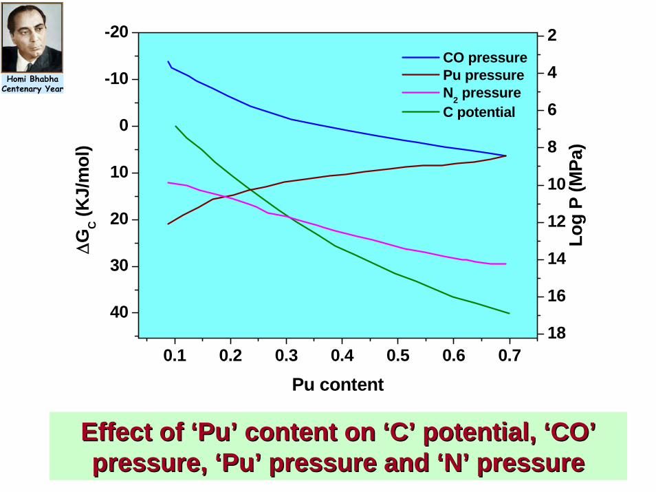
40
30
20
10
0
-10
-20
0.1 0.2 0.3 0.4 0.5 0.6 0.718
16
14
12
10
8
6
4
2
ΔGC (
KJ/
mol
) C potential
Log
P (M
Pa)
Pu content
CO pressure Pu pressure N2 pressure
Effect of Effect of ‘‘PuPu’’ content on content on ‘‘CC’’ potential, potential, ‘‘COCO’’pressure, pressure, ‘‘PuPu’’ pressure and pressure and ‘‘NN’’ pressurepressure
Homi BhabhaCentenary Year

Dec.1-2, 2008 IAEA TM, Fukui 24
SS316 tube with MKI at 973K, 1000hrs.
SS316 / MKI (Class A) at 973K,1000hrs.)
P/C interface
P/C interface
The average hardness of reference samples : 179 VHN (at 973K for 1000hrs) and 152 VHN(1123K for 1000hrs) The hardness data of as received material was 230VHN.
Fuel Clad chemical compatibilityFuel Clad chemical compatibility
INDIA
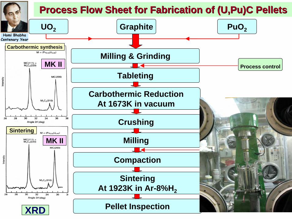
UO2 Graphite PuO2
Milling & Grinding
Tableting
Carbothermic ReductionAt 1673K in vacuum
Crushing
Milling
Compaction
SinteringAt 1923K in Ar-8%H2
Pellet Inspection
Process control
Process control
Process Flow Sheet for Fabrication of (U,Pu)C PelletsProcess Flow Sheet for Fabrication of (U,Pu)C Pellets
XRD
Carbothermic synthesis
Sintering
MK II
MK II
Homi BhabhaCentenary Year

Dec.1-2, 2008 IAEA TM, Fukui 26
Reject RecyclingReject Recycling
Dry Methoda) Mechanical
Pulverization and re-consolidation
b) Thermal Pulverization to oxide phase and re-carbothermicreduction
1200 1300 1400 1500 160010
20
30
40
50
60
70
1470oC
DTA
sig
nal (μV
)
Temperature (oC)
1200 1300 1400 1500 160025
30
35
40
45
50
1440oCD
TA s
igna
l (μV
)
Temperature (oC)
MO2+C
UO2+ PuO2 + C
BARC
Homi BhabhaCentenary Year

Dec.1-2, 2008 IAEA TM, Fukui 27
Sintered Pellets
Mixed Carbide Fabrication lineMixed Carbide Fabrication line
Homi BhabhaCentenary Year
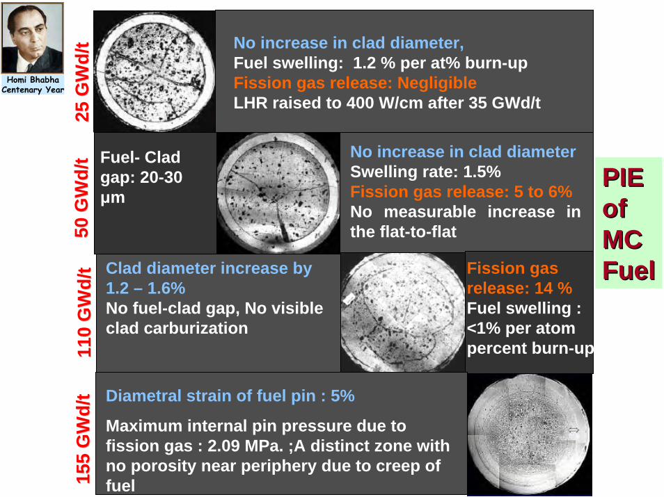
(a)
(c) (d)Fuel- Clad gap: 20-30 μm
No increase in clad diameterSwelling rate: 1.5% Fission gas release: 5 to 6%No measurable increase in the flat-to-flat
Clad diameter increase by 1.2 – 1.6%No fuel-clad gap, No visible clad carburization�
Fission gas release: 14 %Fuel swelling : <1% per atom percent burn-up
25
25 G
Wd/
tG
Wd/
t11
0 11
0 G
Wd/
tG
Wd/
t50
50
GW
d/t
GW
d/t
155
155
GW
d/t
GW
d/t
No increase in clad diameter,Fuel swelling: 1.2 % per at% burn-upFission gas release: NegligibleLHR raised to 400 W/cm after 35 GWd/t
Diametral strain of fuel pin : 5%
Maximum internal pin pressure due to fission gas : 2.09 MPa. ;A distinct zone with no porosity near periphery due to creep of fuel
PIEPIEof of MCMCFuelFuel
Homi BhabhaCentenary Year

Dec.1-2, 2008 IAEA TM, Fukui 29
(U(U--44% 44% PuPu) MOX fuel ) MOX fuel
For Hybrid core of FBTRFor Hybrid core of FBTR
Homi BhabhaCentenary Year

Dec.1-2, 2008 IAEA TM, Fukui 30
Phase StabilityPhase Stability
ThermoThermo--physical Propertiesphysical Properties
Thermal conductivity / diffusivity, thermal expansion, high temperature hardness
FuelFuel-- Coolant Chemical compatibilityCoolant Chemical compatibility
Issues of (UIssues of (U-- 44% PU)MOX fuel44% PU)MOX fuelHomi Bhabha
Centenary Year

1000 1200 1400 1600 18000.5
1.0
1.5
2.0
2.5
3.0
3.5
4.0
4.5
5.0
5.5
T.Jarvis
MOX-Proposed by IGCAR (calculated) UO2 J.K.Fink 1
The
rmal
Con
duct
ivity
(W/m
K)
Temperature (K)
MOX (U0.55 Pu0.45)O2 (RMD)
UO2 Control Sample (RMD)
Thermal conductivity ofThermal conductivity of(U(U0.550.55PuPu0.450.45)O)O2 2 pelletpellet
XX--ray radiograph of MOX (ray radiograph of MOX (UO2--45%PuO45%PuO22) fuel ) fuel ––Sodium compatibility capsulesSodium compatibility capsules
(U(U0.550.55PuPu0.450.45)O)O2 2 pellets pellets After compatibility testsAfter compatibility tests
XRD Pattern of (UOXRD Pattern of (UO22--45% PuO45% PuO22) fuel) fuel
Photomicrograph of MOX pellets after Photomicrograph of MOX pellets after compatibility tests at 700compatibility tests at 700ooC for 400 hC for 400 h

Dec.1-2, 2008 IAEA TM, Fukui 32
X-ray radiograph of fuel-coolant compatibility capsules loaded with MOX (PFBR type) pellets (700C after 400 hrs.)
XX--ray radiographyray radiographyHomi BhabhaCentenary Year

Dec.1-2, 2008 IAEA TM, Fukui 33
Na + MOX
Na
breach
MOX
clad
D9 clad
MOX800C, 260hrs. 700C,450hrs
x200
700C,350hrs
x200
Clad breach
MOX
Na
700C,350hrs
x200
MICROSTRUCTURESMICROSTRUCTURES
Homi BhabhaCentenary Year

FBTR OperationFBTR Operation
1. FBTR now operates with expanded hybrid core of mixed carbide and high PuMOX.
2. 20% of the core is High Pu (45%Pu) MOX.
3. Experimental PFBRMOX fuel assembly at the centre of FBTR.
FBTR Hybrid Core configuration
FBTRHomi Bhabha
Centenary Year

Dec.1-2, 2008 IAEA TM, Fukui 35
Prototype PFBR FA Prototype PFBR FA Irradiation in FBTRIrradiation in FBTR
37 pins of UO2-29%PuO2fabricated at A3F(T), BARC are under irradiation in FBTR.
U233 is added to simulate high linear rating of PFBR with same (U-Pu) chemical composition
FA loaded in the centre of FBTR core
Burn-up reached - 80 GWd/t at 450 W/cm & continuing
37 pin Experimental PFBR MOXFuel
PFBR type MOX pins for experimental irradiation
Homi BhabhaCentenary Year

Dec.1-2, 2008 IAEA TM, Fukui 36
MOX Fuel for PFBR: MOX Fuel for PFBR: Why MOX?Why MOX?1) Industrial scale operational
experience in fuel cycle facilities2) Safe fuel cycle operations and proven
safety response of the MOX fuel in the reactors
3) Economic competitiveness4) High burn-up potential5) Closed fuel cycle with minimum in
and out of core inventory of Pu
Homi BhabhaCentenary Year

Fuel : (Pu-U)O2
Pellet OD/ID : 5.55/1.8 mm
Pin OD/ID : 6.6/5.7 mm
Peak Linear Power : 450 W/cmActive core height : 1000 mmBreeding Ratio : 1.05Clad & Wrapper : 20 % CW D9No.of Pins : 217Width Across Flats : 131.3 mmPeak target Burnup : 100 GWd/tPeak neutron dose : 85 dpa
PFBR FUEL SUBASSEMBLYPFBR FUEL SUBASSEMBLYSalient Details
No of Fuel SA : 181
Total SA : 1758

ERECTION OF SAFETY VESSEL IN PFBR ERECTION OF SAFETY VESSEL IN PFBR
Safety vessel successfully erected on June 24th,2008 – A major mile stone

Dec.1-2, 2008 IAEA TM, Fukui 39
Artistic View of PFBRArtistic View of PFBRHomi Bhabha
Centenary Year

CRO Dep. UO2 Powder PuO2 Powder SS Tubes & Hardwares
Dep.UO2 Pellets
Weighing
Mixing & Milling
Pre-compaction&
Granulation
Final Compaction
Sintering
MOX Pellets Degassing
Stack Making and Loading
Top End PlugWelding (He)
Decontamination
Wire Wrapping &Spot Welding
Fuel Pin Inspection & Storage
Powder Charac. & Chem. Analysis
PuO2 Enrich.
Degassing
Bottom End PlugWelding (Ar)
Loading in Tubes
Degassing
Visual He Leak
Metrology X-Radiography
U,Pu - Analysis,Dissol.
Test,Visual,Dimensional, Linear Mass,Metallography, α - Autorad.
O/M, Total Gas, Metallic & Non-metallic Impurities
Stack Length Check
Visual, He Leak, XGAR, Metrology, X-Radiography, γ - Scan, Cover Gas in Pins
Contamination check
To CSP
Oversize pellets
C.Grinding
Degassed depleted UO2 pellets
PFBR Fuel PinPFBR Fuel PinFabrication Fabrication FlowsheetFlowsheet withwithQC StepsQC Steps
Homi BhabhaCentenary Year

Conveying of powder containers at AFFFConveying of powder containers at AFFF

COMPACTION PRESS AND COMPACTED PELLETSCOMPACTION PRESS AND COMPACTED PELLETS

Inspection of EndInspection of End--plug Welding plug Welding of Dof D--9 Fuel Clad Tubes9 Fuel Clad Tubes
Solidification cracking Defect free weld zone
Probe Water Tank
Clad
Plug
Beam Path
Slit
X-Ray Tube
Fluoroscopy
Pin carriage
REAL TIME MOTION RADIOGRAPHYREAL TIME MOTION RADIOGRAPHY ULTRASONIC END CAP WELD ULTRASONIC END CAP WELD INSPECTIONINSPECTION
Monitor
Metallographic Evaluation
TIG welding Machineinside a glove-box
Homi BhabhaCentenary Year

PFBR FUEL PINSPFBR FUEL PINS

Dec.1-2, 2008 IAEA TM, Fukui 45
Metallic fuels for future Metallic fuels for future FBRsFBRs
Faster Growth Rate (BR 1.3 – 1.4 )
Enhanced Reactor Safety
Integrated Fuel Cycle
BARC
Homi BhabhaCentenary Year

Dec.1-2, 2008 IAEA TM, Fukui 46
Development of Metallic FuelDevelopment of Metallic Fuel
1) Thermophysical, chemical, compatibility and thermodynamicsstudies of metallic fuels.
2) Development of technology for fabrication of fuel/blanket columns for sodium bonded and mechanical bonded fuel and demonstration with U/U-Zr alloy.
Homi BhabhaCentenary Year

Metallic Fuels for FBRSMetallic Fuels for FBRS
Ref metallic fuel for FBR - U-15Pu-10Zr ( Sodium Bonded)
• zirconium increases the liquidus/solidus temperature of (U,Pu) alloy
• retards interdiffusion of fuel and clad constituents
Design for high burn-up metallic fuels• reduction in smear density to 75 % to accommodate swelling
and to reduce FCMI
• provision of adequate gas plenum for fission gas release
• measures to reduce FCCI
Homi BhabhaCentenary Year

Dec.1-2, 2008 IAEA TM, Fukui 48
New Designs of Metallic fuelsNew Designs of Metallic fuels
1. Barrier clad to minimise fuel clad chemical interactions.
2. Mechanical bonding instead of sodium bonding.
3. New U-Pu alloys ( Ternary or Binary ).
Homi BhabhaCentenary Year

300 400 500 600 700 800
750800850900950
1000105011001150120012501300
Tmelt=1243 K Clad limit = 923 K Centreline clad,T91
Tem
pera
ture
(K)
Linear Heat Rate (W/cm)
Maximum LHR for Power to Melt and Eutectic Maximum LHR for Power to Melt and Eutectic formation with T91 Claddingformation with T91 Cladding
Homi BhabhaCentenary Year

Dec.1-2, 2008 IAEA TM, Fukui 50
ASAS--PILGERED CLAD TUBE WITH LINERPILGERED CLAD TUBE WITH LINER
OD = 6.645 – 6.650 mm
ID = 5.39 – 5.44 mm
LINER THICKNESS = 137 – 149 μ
NO GAP WAS FOUND BETWEEN SS TUBE & ZIRCALOY LINER
Homi BhabhaCentenary Year

Dec.1-2, 2008 IAEA TM, Fukui 51
Why Mechanical Bond?Why Mechanical Bond?1. In case of metallic fuels better heat transfer
is ensured by better contact of fuel meat with clad by Swaging operation.
2. Chemical reactivity of sodium during fabrication needs stringent safety measures.
3. Additional head end problems during reprocessing.
4. Non-bond problems – challenges for fabrication, quality control & performance.
5. F.G. column only at the top and also F.G. mobility in sodium.
Homi BhabhaCentenary Year

Dec.1-2, 2008 IAEA TM, Fukui 52
Preparation of U-Zr alloys by Arc Melting
Induction melting with addition of Pu & Injection Casting
Demoulding
Length cutting
ECT for defect detection
Length, diameter & weight measurement
Sodium/Mechanical bonding with clad
Metallic Fuel for Fast Reactors
Swaging Drawing
ECT for Bond Inspection Injection Castingof Uranium
R&D on Fuel Fabrication for R&D on Fuel Fabrication for FBRsFBRs
8mm diameter (Zr clad)6 mm diameter
Homi BhabhaCentenary Year

Dec.1-2, 2008 IAEA TM, Fukui 53
INJECTION CASTING INJECTION CASTING SETSET--UPUP
Mould Pallet up-down mechanism
Top Clamp
Top Chamber
View Port
Bottom Clamp
Bottom Chamber
Control Panel

Dec.1-2, 2008 IAEA TM, Fukui 54
INJECTIONINJECTION--CAST & SWAGED URANIUM RODSCAST & SWAGED URANIUM RODS
LENGTH = 160 mm, DIAMETER = 4.67±0.04
Homi BhabhaCentenary Year

Dec.1-2, 2008 IAEA TM, Fukui 55
COCO--SWAGED SSSWAGED SS--ROD WITH CLAD/LINERROD WITH CLAD/LINER
Zircaloy SS Clad
No Gap
Fuel
Homi BhabhaCentenary Year
Dec.1-2, 2008 IAEA TM, Fukui 56
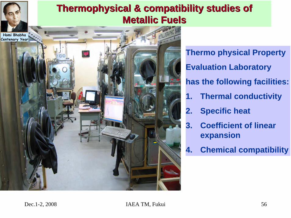
Thermophysical & compatibility studies of Thermophysical & compatibility studies of Metallic Fuels Metallic Fuels
Thermo physical Property
Evaluation Laboratory
has the following facilities:
1. Thermal conductivity
2. Specific heat
3. Coefficient of linear expansion
4. Chemical compatibility
Homi BhabhaCentenary Year

Hardness profile along mechanically Hardness profile along mechanically bonded U/bonded U/ZrZr 4/D4/D--9 composite9 composite
0 100 200 300 400 500 600 700 800 900 10000
50
100
150
200
250
300
350
400
450
U metal Zr-4 D-9 cladHAR
DN
ESS(
Kg/
mm
2 )
DISTANCE FROM D-9 OUTER EDGE(μm)
UZr-4D9
Homi BhabhaCentenary Year

Dec.1-2, 2008 IAEA TM, Fukui 58
SEM of U-Zr-D9 Metallic fuel pin after out-of-pile chemical compatibility test showing no reaction layer at the interfaces.
[thicknesses of ‘Zr’ barrier layer:150μm and D9 cladding material: 450μm ].
a b c(a) As received (b) 650C, 500 hrs; (c) 650C, 1500hrs
UZr
D9 U
U
ZrZr
D9D9
Chemical Compatibility StudiesChemical Compatibility StudiesHomi Bhabha
Centenary Year
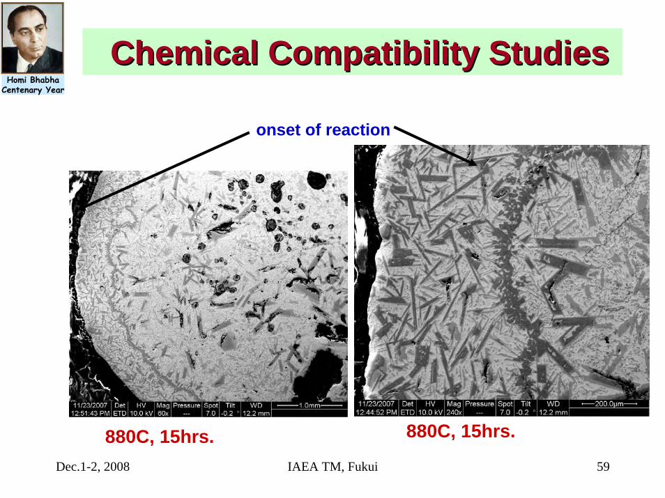
Dec.1-2, 2008 IAEA TM, Fukui 59
880C, 15hrs.
onset of reaction
880C, 15hrs.
Chemical Compatibility StudiesChemical Compatibility StudiesHomi Bhabha
Centenary Year

Dec.1-2, 2008 IAEA TM, Fukui 60
ZrZr
T91T91
U U
U U ZrZr U U
ZrZr
700oC
500hrs 1000hrs 1500hrs
T91T91
ZrZr
U U T91T91ZrZrU U T91T91 ZrZr
U U
650oC
UU
OutOut--ofof--pile Chemical compatibility studies [ U/Zr/T91]pile Chemical compatibility studies [ U/Zr/T91]
Homi BhabhaCentenary Year

Dec.1-2, 2008 IAEA TM, Fukui 61
0 200 400 600 800 1000
0.0
0.5
1.0
1.5
2.0
2.5
3.0
Uranium (Radial) D9 (Radial) Zr (Radial) T 91
Ther
mal
Exp
ansi
on (%
)
Temperature ( 0C )
Thermal expansion values of U, Thermal expansion values of U, ZrZr, D, D--9 and T9 and T--91 91
Homi BhabhaCentenary Year

Dec.1-2, 2008 IAEA TM, Fukui 62
Thorium based MOX Fuels Thorium based MOX Fuels in Nuclear Power in Nuclear Power
a) Prominent Role in Future Nuclear Power Programme.
b) Non-Proliferation Aspects.c) Spent Fuel – Almost a Stable Waste
Form.d) Lower Minor Actinide Generation. e) Lower Reactivity Change with Burn-up.f) Abundance of Resource.
Homi BhabhaCentenary Year

Dec.1-2, 2008 IAEA TM, Fukui 63
Three times more abundant than uranium
Better Performance Characteristics• Higher melting point
• Better thermal conductivity
• Lower fission gas release
• Good radiation resistance and dimensional stability
Better Chemical Stability• Reduced fuel deterioration in the event of failure• No oxidation during permanent disposal in repository• Poses problem in dissolution during reprocessing
Attributes of ThoriumAttributes of ThoriumHomi Bhabha
Centenary Year

Dec.1-2, 2008 IAEA TM, Fukui 64
0
100
200
300
400
500
0 5 10 15Burnup (GWd/t)
Bun
dle
Pow
er (k
W)
Low Flux
Medium Flux
High Flux
PHWR PHWR ThoriaThoria BundlesBundles
Reactor No. of bundles
Madras- I 4Kakrapar-I 35Kakrapar-II 35Rajasthan- II 18Rajasthan -III 35Kaiga-II 35Rajasthan-IV 35Kaiga-I 35
Homi BhabhaCentenary Year

Dec.1-2, 2008 IAEA TM, Fukui 65
Irradiation Experience Of (Irradiation Experience Of (ThTh--PuPu) MOX) MOXin PWL, CIRUSin PWL, CIRUS
Cluster Fuel Clad type GWd/t kW/m
AC-6 (Th-4%Pu)O2
Free standing(TAPS-BWR) 18.5 40
BC-8(Th-6.75%Pu)O2
ThO2
Collapsible(PHWR) 10.2 42
Homi BhabhaCentenary Year

Major Design Objectives• Power output – 300 MWe with 500
m3/d of desalinated water.• A large fraction (65%) of power
from thorium. • Extensive deployment of passive
safety features – 3 days grace period, and no need for planning off-site emergency measures.
• Design life of 100 years.• Easily replaceable coolant
channels.
AHWR is a vertical pressure tube type, boiling light water cooled and heavy water moderated reactor using 233U-Th MOX and Pu-Th MOX fuel.
Advanced Heavy Water ReactorAdvanced Heavy Water Reactor
Salient Features of Pressure tube
• 120mm ID x 6300 mm length• Replaceable through top end-fitting• Unique shape by Pilgering route.• - Thicker at one end, tapering at
the other • Controlled cold work to achieve
required tensile properties.
Gravity driven water pool
Steam drumInclined fueltransfer machine
Fuel storage bay
Fuelling machine
Core

Dec.1-2, 2008 IAEA TM, Fukui 67
Thorium UtilizationThorium Utilization--Initiated by Initiated by PuPu
Advanced Heavy Water Reactor: 300 MWe
Equilibrium Core:Fuel cluster containing 54 pins arranged in 3 rings of 12, 18 and 24 pinsThO2-3.25%PuO2 (outer 24 pins)ThO2-3.75%U233O2 (18 pins)ThO2-3.00%U233O2 (12 pins)Initial core will have fuel assemblies containing all (Th-Pu)MOX pins.
Displacer Rod
(Th-Pu)O2(24 pins)
(Th-U233)O2(30 pins)
Fuel Cluster Cross section
AHWRFuelCluster
Bottom tie plate
Top tie plate
Fuel pin Displacerrod
Water rod
Homi BhabhaCentenary Year
Dec.1-2, 2008 IAEA TM, Fukui 68
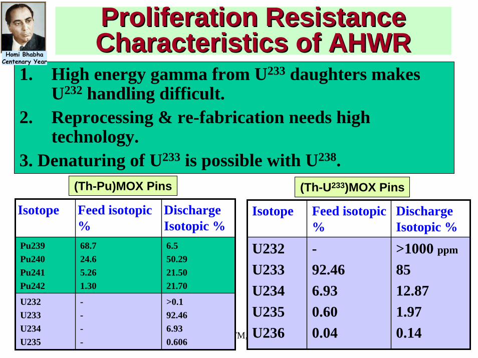
Proliferation Resistance Proliferation Resistance Characteristics of AHWRCharacteristics of AHWR
1. High energy gamma from U233 daughters makes U232 handling difficult.
2. Reprocessing & re-fabrication needs high technology.
3. Denaturing of U233 is possible with U238.
Isotope Feed isotopic %
Discharge Isotopic %
U232U233U234U235U236
-92.466.930.600.04
>1000 ppm
8512.871.970.14
Isotope Feed isotopic %
Discharge Isotopic %
Pu239Pu240Pu241Pu242
68.724.65.261.30
6.550.2921.5021.70
U232U233U234U235
----
>0.192.466.930.606
(Th-Pu)MOX Pins (Th-U233)MOX Pins
Homi BhabhaCentenary Year

Dec.1-2, 2008 IAEA TM, Fukui 69
AHWR Critical FacilityAHWR Critical Facility
Validate reactor physics design on various Fuel types.Reference core consists of 19 element U metallic fuel clusters - 65 Nos.Thoria, (Th-Pu) & (Th-U233)MOX fuel clusters to be introduced in phases for Physics study.Criticality achieved in April 2008.
Fuel for AHWR Critical Facility Built at Trombay to conduct lattice physics experiments for validation of AHWR
Homi BhabhaCentenary Year

Dec.1-2, 2008 IAEA TM, Fukui 70
232U (68 years)α - decay
α - decay
β- - decay
α - decay
α - decay
α - decay
228Th (1.9116 years )
212Pb (10.64 hours )
224Ra (3.66days)
220Rn (55.6 seconds )
216Po( 0.145 second)
208Pb(stable)
212Bi (60.55 minutes )
208Tl ( 3.053 minutes) 212 Po (0.299 μ seconds)
35..94 %α - decay
64.06 %β - decay
β- - decay α - decay
UU232232 Decay ChainDecay Chain
Fabrication of (Th,233U)O2 fuel is difficultbecause it usually contains daughters of232U (half-life 73.6 years) namely, 212Bi and 208Tl, which emit strong gamma radiations.
Therefore the fabrication of the thorium fuel requires operations in the shielded glove-boxes to protect the operators from radiation
Difficulties in making (ThDifficulties in making (Th--U)OU)O22 FuelFuel
212Bi 0.7-1.8 MeV208Tl 2.6 MeV
Gamma Energies of 232U daughters
Homi BhabhaCentenary Year

Dec.1-2, 2008 IAEA TM, Fukui 71
Fabrication Technology for Fabrication Technology for (Th(Th--UU233233) MOX) MOX
Sr.No Technique Flow sheet and
type of facility1 Powder-Pellet Route Fully Shielded Facility2 Sol-gel microsphere
pelletization Fully shielded facility
3 Impregnation (vacuum/microwave of gel/pellet)
Partially shielded facility
4 CAP process(Coated agglomerate
pelletization)Partially shielded facility
Homi BhabhaCentenary Year

Impregnation SetImpregnation Set--up Inside the Glove Boxup Inside the Glove Box
Microstructure of ThO2-4%UO2Fuel made by Impregnation
Homi BhabhaCentenary Year

Dec.1-2, 2008 IAEA TM, Fukui 73
ThO2 UO2
Co- Milling (Planetary ball mill)
Precompaction(140 MPa)
Granulation
Final Compaction(350 MPa)
Centreless grinding
Encapsulation(in zircaloy cladding tube)
SinteringAt 1923K in Ar-8%H2
ThO2 granules
Coating with UO2 powder
Final Compaction(350 MPa)
Centreless grinding
Encapsulation(in zircaloy cladding tube)
SinteringAt 1673K in Air
P/M route
CAP
FlowFlow--sheet for fabricationsheet for fabricationof (Th,U)Oof (Th,U)O22 pelletspellets

Dec.1-2, 2008 IAEA TM, Fukui 74
Fresh ThO2Granules
(precompaction)
Fresh ThO2Agglomerates
(Extrusion)
Fresh ThO2Microspheres
(So-gel Technique)
Coating/blendingwith U233 oxide/
Co-ppt/Master mix
Compaction in rotary press
Sintering in air
Encapsulation
Co-ppted ThO2-50% U3O8 or
pure U233 oxide
UnshieldedFacility
Shielded Facility
Flow sheet for (ThFlow sheet for (Th--UU233233)O)O22 pellet using CAP Processpellet using CAP Process

Duplex Duplex GrainstructureGrainstructure
The interface between two colonies of fine grains indicating that diffusion is complete between two agglomerates
Initial U3O8 coating area
Initial ThO2 particle
Initial ThO2 particle
Homi BhabhaCentenary Year

Dec.1-2, 2008 IAEA TM, Fukui 76
Uranium distributionUranium distributionElemental scan for U Mα, ThMα, and O Kα for ThO2-3.75% UO2 pellet
O Kα
Th Mα
U Mα
Fine grains
Coarse grains
Wt % Wt %Th 84.770 84.236
U 3.120 3.656
O 12.110 12.108
Element
Atom distribution in coarse grains and fine grains for ThO2-4%UO2 pellet determined by EPMA
Homi BhabhaCentenary Year

Dec.1-2, 2008 IAEA TM, Fukui 77
Rock in sand MicrostructureRock in sand Microstructure
The strength of the pellet at room temperature is related to grain size by the Hall- Petchrelation. Accordingly, the smaller grain sized pellets will have higher strength. But at high temperature, the grain boundaries become weaker than grain matrix. Since the pellets of smaller grain size have larger grain boundary areas, these pellets become softer than pellets with larger grain size. Also as the grain size decreases, the creep rate of the fuel increases. Therefore, pellets with smaller grain size have higher creep rate and better plasticity at high temperatures. These pellets will reduce the PCMI.
The basic requirementsfor the high perform-ance of a fuel are:
a) ”Soft pellets”– To reducePellet clad mechanicalinteraction (PCMI).
b) Large grain size –To reduce fission gas release(FGR)
Homi BhabhaCentenary Year

Dec.1-2, 2008 IAEA TM, Fukui 781000 1200 1400 1600 1800
0
2
4
6
8
T.Jarvis
The
rmal
Con
duct
ivity
(W/m
K)
Temperature (K)
95% T.D. ThO2 RMD ThO2+2% UO2 RMD ThO2+4% UO2 RMD UO2 RMD
Thermal Conductivity Data of (Th,U)OThermal Conductivity Data of (Th,U)O22Generated at RMDGenerated at RMD

Dec.1-2, 2008 IAEA TM, Fukui 79
Recycle Fuels in INDIARecycle Fuels in INDIA
PHWR
FBTR
AHWR
Pu Bearing MOX Fuel Fabrication for Thermal & Fast ReactorsScope of work
(U~4%Pu) MOX for BWRs (TAPS)(U~0.4%Pu) MOX for PHWRs (KAPS)
First stage
(U-45%Pu) MOX for FBTR(U-29%Pu) MOX for PFBR(U-70%Pu) MC for FBTR(U-Pu-Zr ) Metal for FBR
Second stage
(Th-3%Pu) MOX - AHWR(Th-3%U233)MOX -AHWRThird stage
Homi BhabhaCentenary Year

Dec.1-2, 2008 IAEA TM, Fukui 80
CLOSED FUEL CYCLE OPTIONCLOSED FUEL CYCLE OPTIONIS ESSENTIAL FOR INDIAIS ESSENTIAL FOR INDIA
“ Development of Nuclear Energy based on a closed fuel cycle enabling fuller use of Uranium & Thorium is the only way to meet the development aspirations of over a billion people while meeting the low emission norms.”
Homi BhabhaCentenary Year

Dec.1-2, 2008 IAEA TM, Fukui 81
Thank YouThank You