home septic system site evaluation and system design inc
TRANSCRIPT

Home Septic System
Site Evaluation
And
System Design
For
Brenda Woods
2634 Wilford Dr.
Toledo OH 43615
616-990-1649
Property Location:
Same As Above
Sylvania Township, Lucas County
Replacement Leach Trench System
By
Nathan Wright
Geophyta, Inc.
2685 C.R. 254
Vickery, OH 43464
419-547-8538
January 28 , 2017
Copyright 2017 Geophyta, Inc.
Geoph
yta, In
c. ©

To The Homeowner:
A septic system is designed based on all the information you provide and Geophyta Inc
collects at the site. It must be accurate. This information includes local soil limits and
topography, plus existing and future locations of your home, number of bedrooms, out
buildings, driveways, drinking water wells, ponds, septic systems, and property lines.
Geophyta Inc. relies on this information to construct detailed design drawings that must
meet local health department regulations before installation.
Any design changes required by the local health department to meet existing
regulations are the responsibility of Geophyta Inc.
Any information changes made by you after the initial site inspection are your
responsibility and will result in additional charges to you above the original quote for
services. These charges may include additional site inspection work, system redesign,
and resubmitted drawings.
To The Installer:
The registered installer of this septic system design is responsible for preparing an “as-
built” record, as stated in the Ohio Administrative Code Chapter 3701-29-09, Par. F
(p.32) of the “Sewage Treatment System Rules,” Ohio Department of Health, January 1,
2015. Additionally, the installer is responsible for measuring and recording distal
pressure head and float switch settings as baseline measures for future operation and
maintenance of any pressure distribution system (3701-29-15, Appendix B, Par. V(p.93)
of above referenced rules.
If the installer requests “as-built” record creation from Geophyta Inc., additional charges
will be billed to the installer by Geophyta Inc. and must be arranged prior to installation.
Geophyta Inc. must assume that any registered installer has the knowledge, equipment,
ability, and experience to properly layout, install, and create as-built drawings for any
septic system design approved by a local board of health. This includes the ability to
read detailed design prints with an associated bill of materials. For this reason, any
Geophyta Inc project supervision prior to or during installation will be billed to the
installer.
Any product substitution made by the installer that is not specifically permitted in the
design prints may result in Health Dept. disapproval and will result in additional re-
design costs billed to the installer.
Copyright 2017 Geophyta, Inc.
Geoph
yta, In
c. ©

Copyright 2017 Geophyta, Inc.
Geoph
yta, In
c. ©

2000 gal Septic
Gravelless Chamber Trenches.5 - 2' W x 72' L. Trenches.Approx. 26' W x 77'L.
Sewer Main
Effluent Main
Area Equal To Soil B; gold
Area Equal To Soil A; purple1000 gal Dose
Approx. Parcel Lines; lt. blue
Fenced Garden; brown
BM1 = 10.00'
Relative Elevation Contours; 3 inch
Approx. WaterLine; drk. blue
9.22 rdedge
9.33 estWater
10.08 tanktp7in
WILF
ORD
wtrline
SoilSiteA
SoilSiteB
8.13 gs7.75 gs
7.74 gs 7.53 gs
8.00 gs
8.67 gs8.56 gs
7.75 gs7.97 gs
8.80 gs
8.58 gs8.66 gs8.88 gs
8.81 gs
9.72 gs
7.69 Bext 7.19 Bext
8.70 pine
8.13 fence8.18 SoilB
10.12 tree
8.53 bigOak
8.28 sumpwell
8.07 fencecrnr
10.02 drvsdwlk
8.06 phoneburie
10.00 sdwlkcrnr
.Geophyta Inc.
Copyright 2017
HSTS Layout - 2634 Wilford Dr
0 30 6015 Feet
Copyright 2017 Geophyta, Inc.
Geoph
yta, In
c. ©
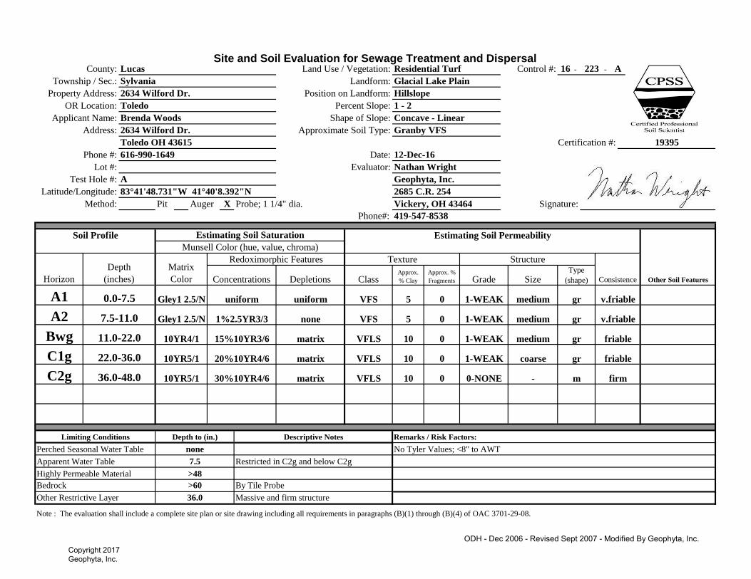
Site and Soil Evaluation for Sewage Treatment and DispersalControl #: - -
Pit Auger Probe; 1 1/4" dia.
Phone#:
Note : The evaluation shall include a complete site plan or site drawing including all requirements in paragraphs (B)(1) through (B)(4) of OAC 3701-29-08.
Vickery, OH 43464
Other Restrictive Layer 36.0 Massive and firm structure
Bedrock >60 By Tile Probe
Highly Permeable Material >48
Apparent Water Table 7.5 Restricted in C2g and below C2g
Perched Seasonal Water Table none No Tyler Values; <8" to AWT
Limiting Conditions Depth to (in.) Descriptive Notes Remarks / Risk Factors:
- m0 0-NONE firmC2g 36.0-48.0 10YR5/1 30%10YR4/6 matrix VFLS 10
gr friablematrix VFLS 10 0C1g 22.0-36.0 10YR5/1 20%10YR4/6
medium gr0 1-WEAK
1-WEAK coarse
friableBwg 11.0-22.0 10YR4/1 15%10YR3/6 matrix VFLS 10
gr v.friablenone VFS 5 0A2 7.5-11.0 Gley1 2.5/N 1%2.5YR3/3
medium gr0 1-WEAK
1-WEAK medium
v.friable
Type
(shape)
A1 0.0-7.5 Gley1 2.5/N uniform uniform VFS 5
Texture Structure
ConsistenceConcentrations Depletions Class Approx.
% Clay
Approx. %
Fragments Grade Size
Soil Profile Estimating Soil Saturation Estimating Soil Permeability
Other Soil Features
Munsell Color (hue, value, chroma)
Horizon
Depth
(inches)
Matrix
Color
Redoximorphic Features
Test Hole #: A Geophyta, Inc.
Method: X
Latitude/Longitude: 2685 C.R. 25483°41'48.731"W 41°40'8.392"N
Signature:
Phone #: 616-990-1649 Date: 12-Dec-16
Certification #:
Lot #: Evaluator: Nathan Wright
19395Toledo OH 43615
Address: 2634 Wilford Dr. Approximate Soil Type: Granby VFS
Applicant Name: Brenda Woods Shape of Slope: Concave - Linear
OR Location: Toledo Percent Slope: 1 - 2
Position on Landform: Hillslope
Township / Sec.: Sylvania Landform: Glacial Lake Plain
16 223 A
419-547-8538
County: Lucas Land Use / Vegetation: Residential Turf
Property Address: 2634 Wilford Dr.
ODH - Dec 2006 - Revised Sept 2007 - Modified By Geophyta, Inc.Copyright 2017 Geophyta, Inc.
Geoph
yta, In
c. ©

Site and Soil Evaluation for Sewage Treatment and DispersalControl #: - -
Pit Auger Probe; 1 1/4" dia.
Phone#:
Note : The evaluation shall include a complete site plan or site drawing including all requirements in paragraphs (B)(1) through (B)(4) of OAC 3701-29-08.
16 223 B
419-547-8538
County: Lucas Land Use / Vegetation: Residential Turf
Property Address: 2634 Wilford Dr. Position on Landform: Hillslope
Township / Sec.: Sylvania Landform: Glacial Lake Plain
Applicant Name: Brenda Woods Shape of Slope: Linear - Convex
OR Location: Toledo Percent Slope: 2 - 3
19395Toledo OH 43615
Address: 2634 Wilford Dr. Approximate Soil Type: Ottokee S
Signature:
Phone #: 616-990-1649 Date: 12-Dec-16
Certification #:
Lot #: Evaluator: Nathan Wright
Test Hole #: B Geophyta, Inc.
Method: X
Latitude/Longitude: 2685 C.R. 25483°41'50.474"W 41°40'8.017"N
Soil Profile Estimating Soil Saturation Estimating Soil Permeability
Other Soil Features
Munsell Color (hue, value, chroma)
Horizon
Depth
(inches)
Matrix
Color
Redoximorphic Features Texture Structure
ConsistenceConcentrations Depletions Class Approx.
% Clay
Approx. %
Fragments Grade Size
loose
Type
(shape)
A 0.0-12.0 10YR3/2 uniform uniform S <5
E 12.0-20.0 10YR6/4 uniform
- sg0 0-NONE
0-NONE - sg looseuniform S <5 0
looseC1 20.0-40.0 10YR5/6 none 1%10YR5/3 FS <5
C2g 40.0-48.0 10YR5/1 10%10YR4/4
- sg0 0-NONE
0-NONE - m firmmatrix VFS <5 0
Perched Seasonal Water Table none Tyler Table: A - C1 horizon (4.0 - 40.0) ILR: S, HLLR: FS
Limiting Conditions Depth to (in.) Descriptive Notes Remarks / Risk Factors:
>48 HLLR = 5.5 gal/day/ft
Apparent Water Table 40.0 Restricted in C2g and below C2g ILR(>30mg/L) = 0.8 gal/day/ft2, ILR(<30mg/L) = 1.6 gal/day/ft
2
Vickery, OH 43464
Other Restrictive Layer 40.0 Massive and firm structure 5xW Soil Absorption Box: 34'Wx87'L
Bedrock >60 By Tile Probe 4 bedroom min. required absorption area = 600 sq.ft.
Highly Permeable Material
ODH - Dec 2006 - Revised Sept 2007 - Modified By Geophyta, Inc.Copyright 2017 Geophyta, Inc.
Geoph
yta, In
c. ©

Subangular Blocky
Schoeneberger, P.J., Wysocki, D.A., Benham, E.C., and Broderson, W.D. (editors) 2002. Field book for describing and
sampling soils, version 2.0. Natural Resources Conservation Service, USDA, National Soil Survey Center, Lincoln, NE.
*Estimate approximate clay percentage within 5 percent Extremely Firm efi
For a more detailed explanation on describing and sampling soils, please refer to the "Field Book for Describing and Sampling Soils"
Very Firm vfi
Silty Clay sic
Clay c Extremely Flaggy XFL
Very Flaggy VFL
Very Friable vfr
Friable fr
Firm fi
Sandy Clay sc Flaggy FL
Silty Clay Loam sicl Extremely Channery XCN
Moist Consistence
Clay Loam cl Very Channery VCN Loose l
Sandy Clay Loam scl Channery
Very Fine Sandy Loam
CN
Silt si Extremely Bouldery XBY
Silt Loam sil Very Bouldery VBY
l Bouldery BY
vfsl Extremely Stony XST * The sizes Very Thin, Thin, Thick, and Very Thick, are used when
describing platy structure only. Substitute thin for fine, and thick for coarse
when describing platy structure.
vk
Fine Sandy Loam fsl Very Stony VST
Sandy Loam sl Stony
Loam
ST
Thick* tk Cloddy CDYCoarse Sandy Loam cosl Extremely Cobbly XCB
Very Thick*
Thin* tn Massive mLoamy Very Fine Sand lvfs Very Cobbly VCB
Single Grain sgLoamy Fine Sand lfs Cobbly CB
Loamy Sand ls Extremely Gravelly XGR
Very Thin* vn
Prismatic pr
Extr. Coarse ec Columnar cpr
Loamy Coarse Sand lcos Very Gravelly VGR Very Coarse vc
Very Fine Sand vfs Coarse Gravelly CGR Platy pl
Medium m sbk
Strong 3 Coarse co
Fine f Angular Blocky abk
Fine Sand fs Medium Gravelly MGR Moderate 2
Very Fine vf Granular gr
Sand s Fine Gravelly FGR Weak 1
Course Sand cos Gravelly GR Structureless 0
Texture Class Abbreviations Textural Class Modifiers Grade Size
R Hard bedrock
Soil Texture Soil Structure
Type (Shape)
C
Little or no pedogenic alteration,
unconsoilidated earthy material, soft bedrock
w Weak color or structure within B
x Fragipan characteristics
B Subsurface accumulation of clay, Fe, Al, Si,
humus; sesquioxides; loss of CaCo3;
subsurface soil structure
p Plow layer or artificial disturbance
r Weathered or soft bedrock
t Illuvial accumulation of silicate clay
E Mineral, loss of Si, Fe, Al, clay, organic
matter
g Strong gley
i Slightly decomposed organic matter
Numerical Prefixes: Used to denote
lithologic discontinuities.
b Buried genetic horizon
A Mineral, organic matter (humus)
accumulation, loss of Fe, Al, clay
d Densic layer (physically root restrictive)
e Moderately decomposed organic matter
Numerical Suffixes: Used to denote
subdivisions within a master
horizon.
O Predominantly organic matter (litter &
humus)
a Highly decomposed organic matter
*Includes glacial till
plain and end moraine
Footslope
Horizon Nomenclature
Master Horizons Horizon Suffixes Horizon Modifiers
Lake Pain Crest Complex
Beach Ridge Hillslope
Terrace Flat Concave
Flood Plain Knoll Linear
Landforms Position on Landform Shape of Slope
Upland* Depression Convex
Copyright 2017 Geophyta, Inc.
Geoph
yta, In
c. ©

Geophyta, Inc.
Owner: 2634 Wilford Dr., Site B Min. Required Actual
Home Size (bedrooms) 4
Water Use (120 gal/day/bedroom) 480 576
Limiting Condition AWT
Depth To Limiting Condition (inches) 40.0
Depth To Bottom of Leach Trench (in.) 36.0
Infiltration Depth (in.) 4.0
Most Limiting Soil Texture S
Tyler Table Values
Infiltration Loading Rate (gal/day/sq. ft) 0.8 0.8
Hydraulic Linear Loading Rate (gal/day/ft) 5.5 5.5
Active Trench Bottom Width (ft)(HLLR/ILR) 6.88
Absorption Line Lengths (ft)(DDF/HLLR) 88
Leachfield Design Requirements Minimum
Required Actual
Active Absorption Area (DDF/ILR)(sq. ft.) 600
Active Absorption Area Adjusted (0.75)(sq. ft.) 450 576
25% Resting Absorption Area (sq.ft.) 113 144
Total Adjusted Absorption Area (sq.ft.) 563 720
Individual Trench Bottom Width (ft) 2.0 2.0
Total Trench Bottom Width (ft) 6.39 10.0
Total Number of Leach Lines 4 5
Active Leach Lines 3 4 - To Adjust For Length
Resting Leach Lines 1 1
Total Lineal Feet of Trench (ft) 352 360
Trench Separation Distance (ft) 6 6
Total Leachfield Width (ft) 20 26
Total Leachfield Length (ft) 88 72 - 18% Length Reduction
In-Soil Leachfield Calculations - Gravelless Chambers
Copyright 2017 Geophyta, Inc.
Geoph
yta, In
c. ©

SCALE 1:175
Drawn By Nathan Wright, Geophyta Inc. 27-Jan-17North
y
2634 Wilfo
rd D
r. Approx. Parcel Line At Road R/W
Electric Pole
Approx. Water Line
House
Sidewalk
New Sewer LineW/Two Way Cleanout.4.0 in. Dia. Sch40 PVC.
Additional Sewer Main Cleanout
Tree
Pine Tree
Big Oak
2000 gal Septic Tank
1000 gal Dose Tank
Force Main.2.0 in. Dia. Sch40 PVC
Soil Stake B
D-Box W/Upflow Forcemain& Flow Equalizers
Distribution Manifold (not shown).4.0in Dia. SD35 PVC.
Gravelless Leach Trenches.5 - 2'W x 72'L.
Trench Soil Inspection Ports (5)
ZONE
REVISIONS
FSCM NO.
BSIZE
DATEDESCRIPTION APPROVED
DWG NO.
REV
SCALE SHEET
2634 Wilford Dr. HSTS - 3D
REV
1:1 1 OF 1
Copyright 2017 Geophyta, Inc.
Geoph
yta, In
c. ©

72' 0"
4' 0"
4' 0"
4' 0"
4' 0"
26' 0"
10' 1"5' 0"
28' 4"
48' 9"13' 2"33' 8"
10' 8"
10' 0"
8' 0"
2' 0"
12' 0"16' 6"
54' 3"
11' 6"
2' 0"
30' 0"4' 0"
2' 11"
10' 0"
SCALE 1:225
Drawn By Nathan Wright, Geophyta Inc. 27-Jan-17
No
rth
y
263
4 W
ilfo
rd D
rive
Tree
Approx.
Approx. Water Line
Pine Tree
Big Oak
D-Box
Water Line Protection Sleeve.10' L 6.0in Dia. Sch40 PVC.Foam Sealed At Both Ends.Centered Over Water Line.
Approx. Parcel Line At Road R/W
Approx.
Soil Stake B
Approx.
BSCALE
REV
FSCM NO. REV
REVISIONS
ZONE DESCRIPTION DATE
SHEET
2634 Wilford Dr. HSTS - Top
APPROVED
DWG NO.SIZE
1:1 1 OF 1
Copyright 2017 Geophyta, Inc.
Geoph
yta, In
c. ©
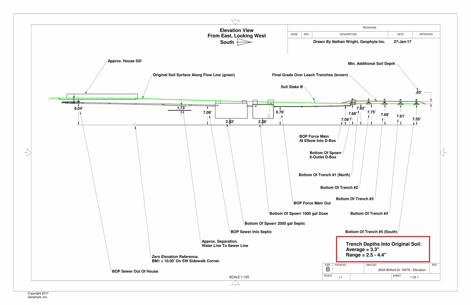
2.42' 2.38'
8.04'7.09'
1.73'6.76'
7.09'
7.68'
7.82'7.75'
7.68' 7.61'7.55'
.83'
SCALE 1:125
Original Soil Surface Along Flow Line (green) Final Grade Over Leach Trenches (brown)
Min. Additional Soil Depth
BOP Sewer Out Of House
Zero Elevation Reference.BM1 = 10.00' On SW Sidewalk Corner.
Approx. Separation.Water Line To Sewer Line
BOP Sewer Into Septic
Bottom Of Spoerr 1000 gal Dose
Bottom Of Spoerr 2000 gal Septic
BOP Force Main Out
BOP Force MainAt Elbow Into D-Box
Bottom Of Spoerr6-Outlet D-Box
Bottom Of Trench #2
Bottom Of Trench #3
Bottom Of Trench #4
Bottom Of Trench #5 (South)
Bottom Of Trench #1 (North)
Soil Stake B
Trench Depths Into Original Soil:Average = 3.3"Range = 2.5 - 4.4"
Approx. House Sill
APPROVEDZONE DESCRIPTION
SHEET
SIZE REVDWG NO.
BFSCM NO.
DATE
REVISIONS
SCALE
REV
2634 Wilford Dr. HSTS - Elevation
1 OF 11:1
Drawn By Nathan Wright, Geophyta Inc. 27-Jan-17
Elevation ViewFrom East, Looking West
South y
Copyright 2017 Geophyta, Inc.
Geoph
yta, In
c. ©

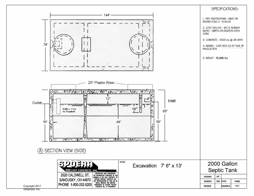
31 "
26 "
Sca
le 1
:30
PL
122
Filt
erA
ttac
hed
Her
e.N
ot
Sho
wn
Ris
ers
As
Gra
de R
equ
ires
: 6,
12,
18,
24"
See
Sep
tic
Tan
kD
etai
l Pri
nt
Fo
rIn
tern
al S
tru
ctu
re.
4" S
ch40
PV
C
Eff
luen
t P
ump
.N
o C
on
cret
e B
lock
Su
pp
ort
s N
eed
ed.
Sp
oer
r C
on
cret
e P
adw
/Con
tro
l Pan
el S
tant
ion
.
1/4"
Dra
inb
ack
Hol
e,R
EQ
UIR
ED
.
Sch
40
PV
C P
ipe
Dia
met
ers
Will
Var
yB
y D
esig
n.
Pu
mp
Co
ntr
olle
r.L
iqu
id L
evel
Co
ntr
ol
Will
Var
y B
y D
esig
n.
Un
ion
Qu
ick
Dis
conn
ect
Min
imu
m D
ista
nce
.A
ctu
al W
ill V
ary.
Sca
le 1
:90
2000
gal
Sep
tic
w/B
affl
es
1000
gal
Do
se w
/Eff
luen
t P
um
p A
ssem
bly
FS
CM
NO
.
A
ZO
NE
RE
VIS
ION
S
RE
V
Spo
err
2000
Sep
tic/1
000
Dos
e w
/Pum
p&F
ilter
SC
ALE
SH
EE
T
DW
G N
O.
DE
SC
RIP
TIO
N
SIZ
E
AP
PR
OV
ED
RE
VD
AT
E
Dra
wn
By
Nat
han
Wri
gh
t, G
eop
hyt
a In
c.
20-D
ec-1
2
vari
ou
s
See
Bill
Of
Mat
eria
ls F
or
All
Co
mp
on
ent
Det
ails
Copyright 2017 Geophyta, Inc.
Geoph
yta, In
c. ©
Copyright 2017 Geophyta, Inc.
Geoph
yta, In
c. ©

PL-122 FilterThe PL-122 was the original Polylok filter. It was the first filter on the market with an automatic shut-off ball installedwith every filter. When the filter is removed for regular servicing, the ball will float up and prevent any solids fromleaving the tank. Our patented design cannot be duplicated.
Features:� Offers 122 linear feet of 1/16” filter slots, which significantly extends time between cleaning.� Has a flow control ball that shuts off the flow of effluent when the filter is removed for cleaning.� Has its own gas deflector ball which deflects solids away.� Installs easily in new tanks, or retrofits in existing systems.� Comes complete with its own housing. No gluing of tees or pipe, no extra parts to buy.� Has a modular design, allowing for increased filtration.
PL-122 Installation:Ideal for residential waste flows up to 1,500 gallons per day(GPD). Easily installs in any new or existing 4" outlet tee.
1. Locate the outlet of the septic tank.2. Remove the tank cover and pump tank if necessary.3. Glue the filter housing to the outlet pipe, or use a Polylok Extend & Lok if not enough pipe exists. 4. Insert the PL-122 filter into tee.5. Replace and secure the septic tank cover.
PL-122 Maintenance:The PL-122 Effluent Filter will operate efficiently forseveral years under normal conditions before requiringcleaning. It is recommended that the filter be cleanedevery time the tank is pumped, or at least every three years.
1. Do not use plumbing when filter is removed.2. Pull PL-122 cartridge out of the tee.3. Hose off filter over the septic tank. Make sure all solids fall back into septic tank.4. Insert filter back into tee/housing.
www.polylok.com 1-877-765-9565Technical Specifications: Page 87
PL-122 Effluent Filter
7
Accepts 1/2” PVCExtension Handle
Alarm Switch(Optional)
122 Linear Ft. of1/16” FiltrationSlots
Filter Housing with3” & 4” Pipe Adapter
Gas Deflector
Automatic Shut-Off Ball
Filter Ready AdapterConnects to Septic Tank Wall
Outdoor SmartFilter® AlarmPolylok, Zabel & Best filters acceptthe SmartFilter® switch and alarm.
1,500 GPD
1/16” Filtration Slots
Polylok offers the only filter on the marketwhere you can get more GPD by simplysnapping our filters together!
1 Filter = 1500 GPD2 Filters = 3000 GPD3 Filters = 4500 GPD
Patent Numbers6,015,488 & 5,871,640
Copyright 2017 Geophyta, Inc.
Geoph
yta, In
c. ©

Copyright 2017 Geophyta, Inc.
Geoph
yta, In
c. ©

SEE BACKSIDE FOR ORDERING INFORMATION.SEE PRICE BOOK FOR LIST PRICE.
FEATURES SPECIFICATIONS
OPTIONS
SJE VERTICALMASTER® II LC CONTROL SwitchMechanically-activated control switch designed to activate low current control panels and alarms.
This control switch offers reliable control for AC and DC applications in non-potable water, and wastewater. The internal switching mechanism has sealed gold cross-point contacts for reliable low current operation. Common applications include PLC (programmable logic controller) panels, IS panels, with intrinsically safe barriers, low current solar barriers, low current solar applications, and other low current control panel and alarm applications.
The SJE VerticalMaster® II LC (Low Current) switch is not sensitive to turbulence.
It is available in normally open (high level) operation only.
n Adjustable activation range of .75 to 6.5 inches (2 to 17 cm).
n Low current, non-arcing applications down to 0.160 mA at 125 VAC
n Includes standard boxed packaging.
n UL Recognized for use in non-potable water.
n CSA Certified.
n Five-year limited warranty.
This switch is available:
n in standard cable lengths of 10 and 20 feet (3 and 6 meters)
CABLE: flexible 18 gauge, 2 conductor (UL, CSA) SJTOW, SJTW
MOUNTING BRACKET & HOSE CLAMP: stainless steel
LIFT ROD: injection molded acetal plastic
FLOAT STOP: neoprene
SWITCH AND FLOAT HOUSING: high impact, corrosion resistant, PVC housing for use in non-potable water up to 52oC (125oF)
Overall dimensions: 12 inch high x 5 inch x 3 inch wide (30.5 cm high x 12.7 cm x 7.6 cm wide)
Switch housing dimensions (excluding cable entrance): 2 inch high x 2.8 inch diameter (5 cm high x 7.1 cm diameter)
Float housing dimensions: 2.5 inch high x 2.7 inch diameter (6.4 cm high x 6.9 cm diameter)
ELECTRICAL: 125 VAC Maximum Electrical Load: 0.1 amps Minimum Electrical Load: 0.160 milliamps30 VDC Maximum Electrical Load: 0.1 amps Minimum Electrical Load: 0.160 milliamps5 VDC Minimum Electrical Load: 1 milliamps
TOP VIEW - CONTACTS CLOSEDTOP VIEW - CONTACTS OPEN
U.S. Patent No. 6,140,925CA Pats. 2,367,577 and 2,694,446Euro Pat. 1203360German Pat. DE69931196T2China Pat. 201110089665.0
PO Box 1708, Detroit Lakes, MN 565021-888-DIAL-SJE • 1-218-847-1317
1-218-847-4617 Faxemail: [email protected]
www.sjerhombus.com 139Copyright 2017 Geophyta, Inc.
Geoph
yta, In
c. ©

SJE VERTICALMASTER® II LC CONTROL Switch
ORDERING INFORMATION
OTHER INFORMATION
SPECIFICATIONS
Mechanically-activated, control switch designed to activate low current control panels and alarms.
NORMALLY OPEN (HIGH LEVEL) OPERATION The control switch closes (turns on) when the float rises signaling a high level, and opens (turns off) when the float drops.
ACTIVATION RANGE: .75 to 6.5 inches (2 cm to 17 cm)
CABLE: flexible 18 gauge, 2 conductor SJTOW, SJTW (UL, CSA)
MOUNTING BRACKET AND HOSE CLAMP: stainless steel
LIFT ROD: injection molded acetal plastic
FLOAT STOP: neoprene
SWITCH AND FLOAT HOUSING: high impact, corrosion resistant, PVC housing for use non-potable water up to 52oC (125oF)
Overall dimensions: 12 inch high x 5 inch x 3 inch wide (30.5 cm high x 12.7 cm x 7.6 cm wide)
Switch housing dimensions (excluding cable entrance): 2 inch high x 2.8 inch diameter (5 cm high x 7.1 cm diameter)
Float housing dimensions: 2.5 inch high x 2.7 inch diameter (6.4 cm high x 6.9 cm diameter)
ELECTRICAL:125 VAC Maximum Electrical Load: 0.1 amps Minimum Electrical Load: 0.160 milliamps30 VDC Maximum Electrical Load: 0.1 amps Minimum Electrical Load: 0.160 milliamps5 VDC Minimum Electrical Load: 1 milliamps
OPTIONS MOUNTING BRACKET AND HOSE CLAMP ARE STANDARD
BOXED PACKAGING IS STANDARD Bulk packaging is not available.
UL Recognized for Water & Sewage
Cat Page PN 1039864B©SJE-Rhomb us 09/14
Part Number DescriptionShippingWeight
1025024 10VMIILC BOX 1.65 lbs.1039781 20VMIILC BOX 2.36 lbs
Normally Open
SEE PRICE BOOK FOR LIST PRICE.
Call or fax your order!1-888-DIAL-SJE (1-888-342-5753) n Fax 218-847-4617
Product offering and pricing are subject to change without notice.Please visit www.sjerhombus.com for the most current information.140 Copyright 2017
Geophyta, Inc.
Geoph
yta, In
c. ©

CPE 4/10HP & 1/2HPEffluEnt
ww
w.cham
pionpump.com
CPE5A–12
CPE5V–12
Distributed by:
FEAturEs / BEnEFits■ High Efficient Motor With Upper & Lower Ball
Bearings / Runs Cooler & Last Longer■ Cast Iron Vortex Impeller / Helps Prevent Clogging■ Inboard Seal-Rotating Components Of Seal
Are In The Motor Housing, Lubricated By TheMotor Oil / Seal Will Last Longer If Pump RunsDry, Hair And Debris Cannot Wrap Around SealComponents
■ Secondary Exclusion Seal / Keeps Debris FromEntering Seal Cavity
■ Sealed Entry-Replaceable Power Cord / EasyTo Replace In The Field, Prevents Water FromEntering The Motor Housing Through A CutPower Cord (Up To 50’ Available)
■ Piggy-Back Switch Design / Defective SwitchesCan Be Diagnosed By Phone; Pump Can BeOperated Manually by Overriding The Switch
■ Every Pump Is Tested In Water / Ensures That ThePump Meets Head & Flow Requirements
APPLiCAtiOns■ Dewatering, Elevator Pits, Septic Systems
CHAmPiOn PumP – PumP PErFOrmAnCE CurVE
30
40
50
0
10
20
tota
l Hea
d in
Ft
60
30 50400 2010Gallons Per minute
60 70
CPE4
CPE5
CPEf5
8.1 - - - - - - - - - - - - - - - - - - - - - - - - - -- -| |
Copyright 2017 Geophyta, Inc.
Geoph
yta, In
c. ©

CPE 4/10HP & 1/2HPEffluEnt
ww
w.cham
pionpump.com
model HP Volts Phase Amps Cord Length switch
CPE4-12 • CPE5-12 • CPEF5-12 4/10 • 1/2 • 1/2 115 1 6.6 • 7.2 • 8.5 20 Manual
CPE4-22 • CPE5-22 • CPEF5-22 4/10 • 1/2 • 1/2 230 1 3.3 • 3.6 • 4.3 20 Manual
CPE4-13 • CPE5-13 • CPEF5-13 4/10 • 1/2 • 1/2 115 1 6.6 • 7.2 • 8.5 30 Manual
CPE4-15 • CPE5-15 • CPEF5-15 4/10 • 1/2 • 1/2 115 1 6.6 • 7.2 • 8.5 50 Manual
CPE4A-12 • CPE5A-12 • CPEF5A-12 4/10 • 1/2 • 1/2 115 1 6.6 • 7.2 • 8.5 20 Float
CPE4A-22 • CPE5A-22 • CPEF5A-22 4/10 • 1/2 • 1/2 230 1 3.3 • 3.6 • 4.3 20 Float
CPE4A-13 • CPE5A-13 • CPEF5A-13 4/10 • 1/2 • 1/2 115 1 6.6 • 7.2 • 8.5 30 Float
CPE4V-12 • CPE5V-12 • CPEF5V-12 4/10 • 1/2 • 1/2 115 1 6.6 • 7.2 • 8.5 20 Vertical Float
CPE4V-22 • CPE5V-22 • CPEF5V-22 4/10 • 1/2 • 1/2 230 1 3.3 • 3.6 • 4.3 20 Vertical Float
Champion Pump Company, inc • 400 Orange Street, Suite L-22 • Ashland, OH 44805phone 419-207-3960 • toll free 800-659-4491 • fax 419-207-3962
DisCHArGE 2” NPT. Vertical
sOLiDs HAnDLinG 3/4”
LiQuiD tEmPErAturE 140 Degrees F. (Intermittent)
mOtOr HOusinG Cast Iron
VOLutE Cast Iron
sEAL PLAtE Cast Iron
imPELLEr Cast Iron
sHAFt Stainless Steel
sHAFt sEAL Inboard Mechanical With Secondary Exclusion SealCarbon - Rotating FaceCeramic - Stationary FaceBuna-N - Elastomer300 Series Stainless Steel - Hardware
BEArinG (uPPEr & LOWEr) Single Row, Ball, Oil Lubricated
HArDWArE 300 Series Stainless Steel
sQuArE rinGs Buna-N
COrD (UL / CUL) Listed 16 AWG, Type SJTW 20’ Length Standard. Other Lengths Available.
COrD EntrY Compression Grommet – Outer Jacket SealQuick Disconnect Pin Terminals
mOtOr (sinGLE PHAsE) 4/10 & 1/2 HP, 3450 RPM. 60HzNEMA L Includes Overload Protection In The Motor.Oil Filled, Class BPermanent Split Capacitor
WEiGHt 35lbs (Manual)
Copyright 2017 Geophyta, Inc.
Geoph
yta, In
c. ©
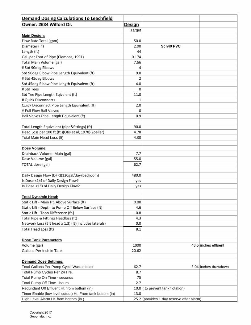
Demand Dosing Calculations To LeachfieldOwner: 2634 Wilford Dr. Design
Target
Main Design:
Flow Rate Total (gpm) 50.0
Diameter (in) 2.00 Sch40 PVC
Length (ft) 44
Gal. per Foot of Pipe (Clemons, 1991) 0.174
Total Main Volume (gal) 7.66
# Std 90deg Elbows 4
Std 90deg Elbow Pipe Length Equivalent (ft) 9.0
# Std 45deg Elbows 2
Std 45deg Elbow Pipe Length Equivalent (ft) 4.0
# Std Tees 0
Std Tee Pipe Length Eqivalent (ft) 11.0
# Quick Disconnects 1
Quick Disconnect Pipe Length Equivalent (ft) 2.0
# Full Flow Ball Valves 0
Ball Valves Pipe Length Equivalent (ft) 0.9
Total Length Equivalent (pipe&fittings) (ft) 90.0
Head Loss per 100 ft.(ft.)(Otis et al, 1978)(Zoeller) 4.78
Total Main Head Loss (ft) 4.30
Dose Volume:
Drainback Volume: Main (gal) 7.7
Dose Volume (gal) 55.0
TOTAL dose (gal) 62.7
Daily Design Flow (DFR)(120gal/day/bedroom) 480.0
Is Dose <1/4 of Daily Design Flow? yes
Is Dose <1/8 of Daily Design Flow? yes
Total Dynamic Head:
Static Lift - Main Ht. Above Surface (ft) 0.00
Static Lift - Depth to Pump Off Below Surface (ft) 4.6
Static Lift - Topo Difference (ft.) -0.8
Total Pipe & Fittings Headloss (ft) 4.3
Network Loss (5ft head x 1.3) (ft)(includes laterals) 0.0
Total Head Loss (ft) 8.1
Dose Tank Parameters
Volume (gal) 1000 48.5 inches effluent
Gallons Per Inch in Tank 20.62
Demand Dose Settings:
Total Gallons Per Pump Cycle W/drainback 62.7 3.04 inches drawdown
Total Pump Cycles Per 24 Hrs. 8.7
Total Pump On Time - seconds 75
Total Pump Off Time - hours 2.7
Redundant Off Effluent Ht. from bottom (in) 10.0 ( to prevent tank flotation)
Timer Enable (low level cutout) Ht. From tank bottom (in) 13.0
High Level Alarm Ht. from bottom (in.) 25.2 (provides 1 day reserve after alarm)
Copyright 2017 Geophyta, Inc.
Geoph
yta, In
c. ©

Add Risers As Needed To Bring Lid Above Final Grade
Force Main Diameter Will Vary By Design
Force Main Must HaveDrainback For Freeze Protection
Upflow Section Of Force Main
Roto-Flow or Equalizer Pipe InsertsFor Each Outlet For Balanced Flow
Individual Designs May Not RequireDouble 90 Ell.
DWG NO.FSCM NO.
ZONE
SHEET
DATE APPROVED
SCALE
REV
REVISIONS
DESCRIPTION
6 Outlet D-Box W/Upflow Forcemain
SIZE REV
A
1:1 1 OF 1
Drawn By Nathan Wright, Geophyta Inc. 24-May-16
Copyright 2017 Geophyta, Inc.
Geoph
yta, In
c. ©

Equalizer
The Equalizer’s patented weir opening maintainsequal flow, even in unlevel D-Boxes thatcontinue to move their entire lives.Equalizer Features:� Maintains equal flow from distribution box.� Automatically compensates for box movement.� Engineered plastic is non-corrosive. ��Extends septic system life.� Inserts without tools.� Resets equal flow when D-Box has moved.
1-877-765-956542
Roto-Flow
Roto-Flow enables equal distribution to yourleaching fields. Available in 3” and 4” sizes.
The Roto-Flow is the low cost solution to yourD-Box flow regulating problems. The simpleRoto-Flow for D-Box outlet pipes gives youthe easiest “set & forget” flow regulatoravailable.
The Roto-Flow fits Schedule 40, SDR 35 andthin wall pipe sizes. Both 3 inch and 4 inch sizesare available. Simply place the Roto-Flow intothe D-Box outlet pipe then adjust to equalizeflow.
The Roto-Flow is made from HDPE; it isdesigned to stand up in the septic environmentwithout failing. Our Roto-Flow design ensuresa good fit in all pipe sizes.
The Roto-Flow is made to fit pipes withoutcollapsing or creating a loose fit. This willguarantee equal flow performance.
www.polylok.comTechnical Specifications: Page 119 - 120
Roto-Flow & Equalizer
4” 3”
izer
Simple to install, just pushinto any 4”pipe, SCHD 40,SDR 35, or thin wall.
Adjustment knob movesopening up or down in 1/16”increments; total is 7/8”.
Water tight fit.
Tough engineered plasticwill not corrode and installswithout tools.
�
�
���
�
��
Custom Distribution Boxes with Equalizers installed
PATENTS: U.S.A. - 5,680,989 - 5,154,353 - 5,107,892
Copyright 2017 Geophyta, Inc.
Geoph
yta, In
c. ©

8.0"
6.0"
24.0"3.3"
nnnn4.5"
nnnn4.0"
16.3"
O.D. DistributionManifold Pipe Entry
Trench Width,May Be 36" In Some Designs
Dome Height
Minimum Soil Cover.Silt Loam Or Better TextureWith Moderate Or StrongStructure When Soil Is AddedMore Than 2" Above Original Grade
Height Of Distribution Pipe Entry
Length Will Vary By Design
Trench Bottom Inpection Port
Infiltrator All-In-One Endcap
Infiltrator Standard Endcap
Soil Surface
DATE
REVISIONS
DWG NO.
SHEET
Standard Gravelless Leach Trench
ZONE
ASCALE
REV
REV
FSCM NO.SIZE
DESCRIPTION APPROVED
Drawn By Nathan Wright, Geophyta Inc. 4-Apr-15
DO NOT DIG TRENCHES IF SOIL WILL SMEAR
If Trench Sidewall & Bottom Smearing OccursDuring Excavation, Then Rake Sidewalls &Bottoms To Break This Smear Layer
1:15
Copyright 2017 Geophyta, Inc.
Geoph
yta, In
c. ©
1ACAD No.Checked
DateDrawn By:
Scale NOT TO SCALE
12/18/2009RWD
INFILTRATOR SYSTEMS, INC. 6 BUISNESS PARK ROAD
P.O. BOX 768OLD SAYBROOK, CT 06475
PH. (800) 221-4436FX. (860) 577-7001
WWW.INFILTRATORSYSTEMS.COM
Sheet Of
DFH
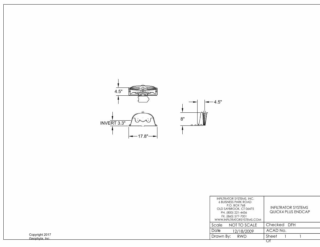
INFILTRATOR SYSTEMS QUICK4 PLUS ENDCAP
1
17.8"
4.5"
INVERT 3.3"
4.5"
8"
Copyright 2017 Geophyta, Inc.
Geoph
yta, In
c. ©

1ACAD No.Checked
DateDrawn By:
Scale NOT TO SCALE
12/18/2009RWD
INFILTRATOR SYSTEMS, INC. 6 BUISNESS PARK ROAD
P.O. BOX 768OLD SAYBROOK, CT 06475
PH. (800) 221-4436FX. (860) 577-7001
WWW.INFILTRATORSYSTEMS.COM
Sheet Of
DFH
INFILTRATOR SYSTEMS QUICK4 PLUS EQUALIZER
36 LOW PROFILE
1
QUICK4 PLUS EQUALIZER 36 LOW PROFILE (LP) CHAMBERSTOP VIEW
SIDE VIEWFRONT VIEW
22"
8"
48"(EFFECTIVE LENGTH)
52"
Copyright 2017 Geophyta, Inc.
Geoph
yta, In
c. ©
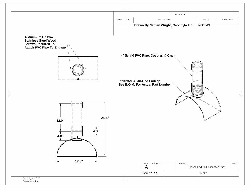
4.0"
12.0"
4.3"
24.4"
17.8"
A Minimum Of TwoStainless Steel WoodScrews Required ToAttach PVC Pipe To Endcap
4" Sch40 PVC Pipe, Coupler, & Cap
Infiltrator All-In-One Endcap.See B.O.M. For Actual Part Number
A
REVISIONS
ZONE DESCRIPTION
SCALE
DATE APPROVED
DWG NO.
SHEET
FSCM NO.SIZE
REV
REV
Trench End Soil Inspection Port
1:10
Drawn By Nathan Wright, Geophyta Inc. 9-Oct-13
Copyright 2017 Geophyta, Inc.
Geoph
yta, In
c. ©
1ACAD No.Checked
DateDrawn By:
Scale NOT TO SCALE
12/18/2009RWD
INFILTRATOR SYSTEMS, INC. 6 BUISNESS PARK ROAD
P.O. BOX 768OLD SAYBROOK, CT 06475
PH. (800) 221-4436FX. (860) 577-7001
WWW.INFILTRATORSYSTEMS.COM
Sheet Of
DFH
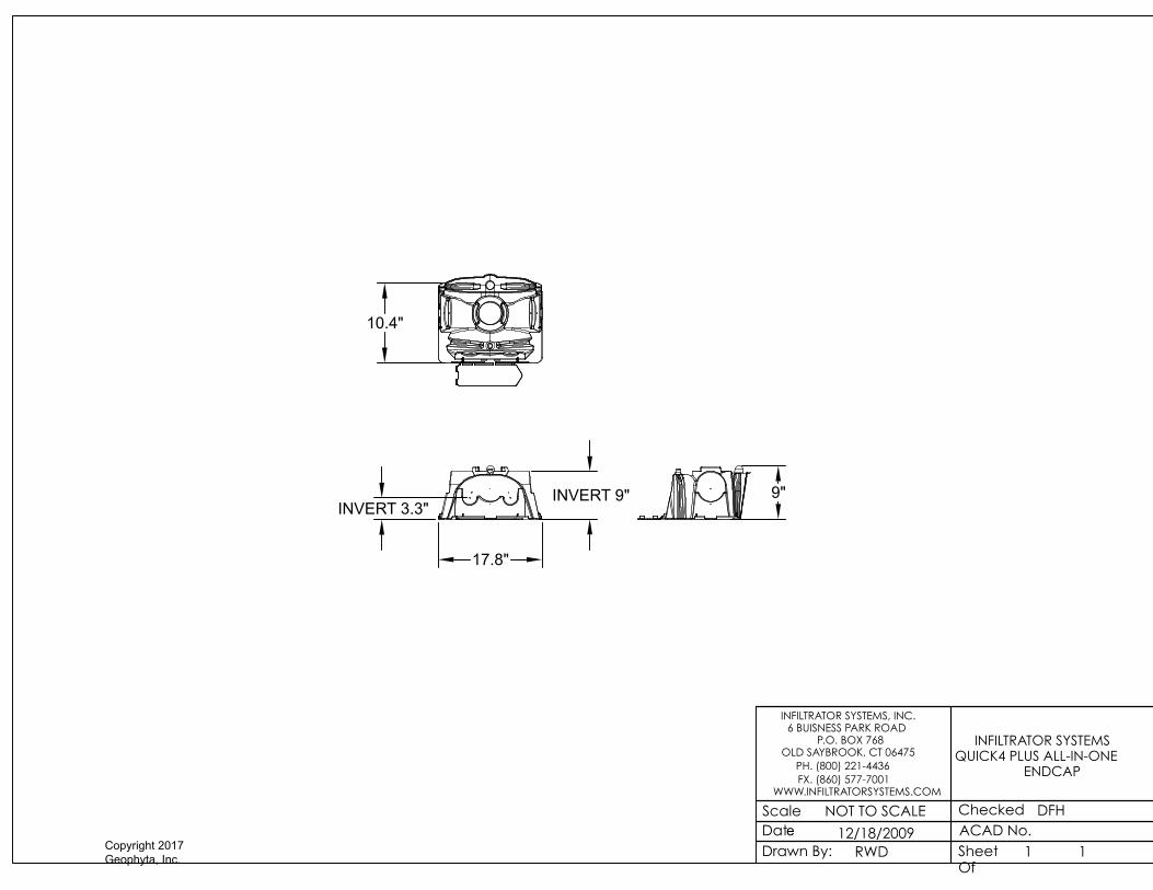
INFILTRATOR SYSTEMS QUICK4 PLUS ALL-IN-ONE
ENDCAP
1
17.8"
INVERT 3.3"
10.4"
9"INVERT 9"
Copyright 2017 Geophyta, Inc.
Geoph
yta, In
c. ©

Quantity Part Name Section Comment
8 SCH40PVC4inchpipe10ft Sewer Main
1 SCH40PVC4inchpipe36in Sewer Main
2 SCH40PVC4inchpipe4ft Sewer Main
7 Sch40PVC4.0inchCoupler Sewer Main
2 Sch40PVC4.0inchTwoWayCleanoutTeeSxSxS Sewer Main
4 Sch40PVC4.0inch45Ell Sewer Main
3 SCH40PVC4inchpipe2ft Sewer Main
2 Sch40PVC4inchCap Sewer Main
1 SCH40PVC6inchpipe10ft Water Line Protection Sleeve
1 ClosedCellSprayFoam Water Line Protection Sleeve
1 Spoerr2000galSeptic12inchRisers Septic Tank Spoerr 2000 gal Septic
1 PolyLokPL122Filter Septic Tank PolyLok or equiv.
1 SCH40PVC4inchpipe3ft Septic To Dose
1 Spoerr1000DoseTankW18inRiser Dose Tank Spoerr 1000 gal Dose
1 Effluent Pump 2inchNPT0.4hp Dose Pump Assembly
1 SJERhombus Control SwitchForDemandDose Dose Pump Assembly
1 HighLevelAlarmFloat Dose Pump Assembly
~100 ft. 2 conductor w/ground, 14 gauge UG wire Dose Pump Assembly Pump Circuit; Standalone Breaker
~100 ft. 2 conductor w/ground, 14 gauge UG wire Dose Pump Assembly Alarm Circuit, Added To House Lighting Breaker
~100 ft. Plastic conduit, to contain 6-14ga Dose Pump Assembly Pump & Alarm Circuit
3 Sch40PVC2.0inch90Ell Dose Pump Assembly
1 SCH40PVC2.0inchpipe12inW0.25weephole Dose Pump Assembly Must Have Drainback
1 SCH40PVC2.0inchpipe12in Dose Pump Assembly
1 SCH40PVC2.0inchAdapterMNPTtoSoc Dose Pump Assembly
1 SCH40PVC2.0inchpipe12.586in Dose Pump Assembly
2 SCH40PVC2.0inchpipe3in Dose Pump Assembly
1 SCH40PVC2.0inchpipe60.8in Dose Pump Assembly
2 SCH40PVC2.0inchpipe6in Dose Pump Assembly
1 Sch40PVC2.0inchUnionSxS Dose Pump Assembly
1 SCH40PVC2.0inchpipe3.5ft Dose Pump Assembly
3 Sch40PVC2.0inch90Ell Force Main
4 SCH40PVC2.0inchpipe10ft Force Main
4 Sch40PVC2.0inchCoupler Force Main
1 Sch40PVC2.0inch45Ell Force Main
1 DistributionBox6outlet Distribution Manifold Spoerr 6-Outlet
~ Misc. 4.0in Dia. SD35 PVC Pipe Distribution Manifold
~ Misc. 4.0in Dia. SD35 PVC Pipe Fittings Distribution Manifold
5 PolyLokRotoFlowInsert4.0inch Distribution Manifold PolyLok or equiv.
5 InfiltratorQ4PlusEQ36LPEndCap Leach Trenches
5 DomeStraightTrench2ftWx4ftLx8inH18SectQ4PlusEQ36LP72ftTotal Leach Trenches 90 - Chambers
- Topsoil Leach Trenches 69.3 cu.yd. ~= 121 tons Fine Sandy Loam
5 Sch40PVC4inchCap Trench Soil Inspection Port
5 Sch40PVC4.0inchCoupler Trench Soil Inspection Port
5 SCH40PVC4inchpipe1ft Trench Soil Inspection Port
5 SCH40PVC4inchpipe4.0in Trench Soil Inspection Port
10 StainlessSteelWoodScrew Trench Soil Inspection Port
5 InfiltratorQ4PlusAllInOneEndCap Trench Soil Inspection Port
1 Grass Seed 2lbs./1,000 sq.ft.K.Bluegrass ~2000 sq. ft.; 4.0 lbs.
1 Straw Mulch For Grass Establishment Homeowner's Choice ~2000 sq. ft.
1 Grass Establishment Fertilizer 10 lbs. 20-10-10/1,000 sq. ft. ~2000 sq. ft.; 20 lbs.
1 Call OUPS before you dig.
Bill Of Materials - 2634 Wilford Dr. HSTS Shallow Leach Trenches
Installer substitution of materials not specfied in this Bill Of Materials may void
Health Dept. approval of this design and will result in a re-design fee and is the
sole responsibility of the installer.
Design Prints Take Precedence Over This Bill of Materials. This is a best
estimate of materials required and is provided as a convenience to
installers. This BOM is not required for design approval.
Copyright 2017 Geophyta, Inc.
Geoph
yta, In
c. ©

Copyright, 2011 Geophyta, Inc. Page 1 of 4
Operation and Maintenance Procedures
Home Septic Treatment Systems With
Effluent Distribution Through In-Soil Leach Trenches
Home septic treatment systems are biologically based systems. They rely on both anaerobic and aerobic
microorganisms to process human waste. These systems may utilize processing, storage, and pumping
tanks. A soil absorption component, the leachfield, also processes, treats, and disperses septic effluent.
Any abuse of this biological treatment system will result in less efficient sewage treatment and early
failure of your new system.
Improper operation and/or maintenance of your home septic treatment system
will result in its failure.
Geophyta, Inc. strongly recommends that a homeowner hire a professional
service provider to inspect and maintain your system. Your county health
department has a list of registered service providers. Make sure that your
service provider has septic tank and leachfield maintenance experience.
1) Homeowner Responsibility:
a) The system owner is responsible for the continuous operation and maintenance of this home
septic treatment system
b) Your county health department may require third-party inspection and maintenance of your
home septic treatment system.
c) Home Interior Design & Appliance Selection:
i) Install water conserving fixtures such as low flow shower heads, low flow toilets, and front
loading washers.
ii) Space out water use throughout the day and week. Avoid doing all laundry in one day.
iii) Repair all water leaking fixtures.
iv) Eliminate garbage disposals, or limit their use. Collect food scraps with sink strainers for
disposal as trash or for composting; this includes coffee grounds.
v) DO NOT pipe sump pump output into your sewer line.
d) Home Landscaping Limitations:
i) Do not pipe roof downspouts or any other rainwater drainage into the septic or dose tanks.
ii) Divert all downspouts or other rainwater drainage away from your entire septic system.
iii) Divert all downspouts or other rainwater drainage away from the leachfield area.
iv) Do not drive or park cars, boats, heavy equipment, or other vehicles on or near septic
system tanks and leachfield areas.
Copyright 2017 Geophyta, Inc.
Geoph
yta, In
c. ©

Copyright, 2011 Geophyta, Inc. Page 2 of 4
v) Do not add additional soil fill on or near the leachfield. This will limit air movement into the
soil needed for effluent treatment and may cause system failure.
vi) Limit lawnmower traffic on the leachfield when soil is excessively wet.
vii) Do not plant any deep rooted plants on top of or near your leachfield soil absorption area.
e) Home Resident Responsibilities:
i) Only flush or drain bio-degradable human waste, toilet paper, laundry and dish and personal
care soaps, and water into your home septic treatment system.
ii) Severely limit disposal of food fats, oils, and greases. These will clog your system.
iii) Do not flush or drain undiluted bleach, cleansers, or drain cleaners.
iv) Do not flush any non-biodegradable items. For example, plastic items.
v) Do not flush or drain motor oils, greases, anti-freezes, cleaners, etc.
vi) Do not flush cat litter.
vii) Do not flush paper towels, facial tissue, cigarette butts, disposable diapers, sanitary napkins,
tampons, or condoms.
viii) Do not flush prescription or over-the-counter drugs. Antibiotics and cancer treatment drugs
are very harmful to your home septic treatment system.
ix) Do not dump solvents like dry cleaning fluid, pesticides, photographic chemicals, paint
thinner down the drain.
x) Don't use septic tank additives, unless health department approved.
xi) Don't drain a hot tub or large amounts of water into your septic system.
f) Home Improvement/Expansion:
i) Contact your county sanitarian before adding new driveways, decks, patios, pools, and
outbuildings not identified on your original layout plan to make sure all setback distances
from your septic system tanks and mound are met.
ii) Contact your county sanitarian before adding bedrooms and/or increasing your home
occupancy. This may overload your septic system. Septic system expansion may be
required to prevent failure.
g) Homeowner Cautions:
i) DO NOT ENTER TANKS WITHOUT PROPER SAFETY EQUIPMENT. Septic and dose tanks
contain noxious and deadly gases.
ii) Pump or dose tanks and control boxes contain electrical components. ELECTRICAL SHOCK
HAZARD CAN EXIST WITH IMPROPERLY WIRED OR FAILING COMPONENTS.
iii) Always keep tank fall guards in place, except for the time needed to replace components
when safety equipment is present.
iv) Always replace and secure septic and dose tank lids after completing any inspection.
v) Any disconnection or removal of filters, screens, floats, alarms, and/or control panels will
result in system failure.
vi) Contact your county sanitarian for allowed homeowner maintenance and repair of your
septic system.
Copyright 2017 Geophyta, Inc.
Geoph
yta, In
c. ©

Copyright, 2011 Geophyta, Inc. Page 3 of 4
2) Inspection & Maintenance Requirements:
a) Perform inspection & maintenance every six months.
b) Review Baseline Operation and Maintenance Data:
i) The installer of your system set and recorded all float/liquid level heights, pump down
times, cycles per day, and distal head pressures required in the design specifications.
ii) Review all previous six month inspection data.
c) Identify any house additions, patios, pools, ponds, driveways, outbuildings, etc. added since the
last inspection that may impact the home septic treatment system. Draw a sketch of these
differences.
d) Inspect the house sewer main two-way cleanout tee bottom:
i) Check for clogging.
ii) Check for continuous clear water flows from the home.
e) Evaluate Septic Tank & Pump Tank:
i) Measure sludge and scum depths; pump tank when cumulative thickness is 1/3 of the tank
depth.
ii) Look for signs of clogging and tank damage.
iii) Look for signs of tank and riser leakage.
iv) Clean & inspect septic tank outlet filter.
v) Make sure lids are securely attached to risers.
f) Evaluate Pump/Dose Tank & Pumping Equipment:
i) Measure sludge and scum depths; pump tank when septic tank is pumped.
ii) Look for signs of clogging and tank damage.
iii) Look for signs of tank and riser leakage.
iv) Inspect and assure proper functioning of floats or other liquid level controls.
v) Clean and inspect dose pump outlet filter. May not be present in some designs.
vi) Inspect and assure proper condition and functioning of the effluent pump.
vii) Make sure lids are securely attached to risers.
g) Evaluate Drain Fields:
i) Inspect all leachfield soil inspection tubes for surface condition, surface color, and depth of
ponded effluent, if present.
ii) Look for surfacing effluent.
iii) Look for excessively moist soil around leachfield area.
iv) Identify appropriate vegetative cover.
v) Look for surface disturbances, compaction, abnormal settling, and erosion.
vi) Identify any deep rooted vegetation recently planted near the leachfield area.
h) Switch leachfield resting trench in D-box:
i) Determine a rotation sequence for closing off flow to the resting trench/trenches.
ii) Open the previously rested leach trench.
iii) Close the next trench in sequence for resting.
i) Measure Pump Run Time and/or Drawdown:
i) For demand dosed systems, verify original design effluent drawdown depth.
Copyright 2017 Geophyta, Inc.
Geoph
yta, In
c. ©

Copyright, 2011 Geophyta, Inc. Page 4 of 4
ii) For time dosed systems, verify original design pump run time.
iii) For systems with a cycle counter or run time meter, record the current values.
j) Test Alarms:
i) Evaluate proper function of low liquid level alarm.
ii) Evaluate proper function of high liquid level alarm and warning light.
3) Findings & Repairs:
a) All findings during inspection and maintenance must be recorded.
b) Any system adjustments must be recorded.
c) Any system deficiencies, worn out components, and/or damage must be repaired to return your
septic system to a properly functioning state.
d) All repairs must be recorded.
Copyright 2017 Geophyta, Inc.
Geoph
yta, In
c. ©