home heat tank systems technical standards … home heat tank systems technical standards handbook...
TRANSCRIPT
Home Heat Tank Systems
Technical Standards Handbook
November 30, 2012 (Amended June 1 2015)
Preface
This Home Heat Tank Systems Technical Standards Handbook has been prepared to assist licensed installers, home inspectors, and other individuals who may be involved with home heat tank systems in the inspection, alteration and installation of home heat tanks. The principle intention of this handbook is to support a new administrative approach to the installation of home heat tank systems, whereby the construction standards previously in the regulations have been removed and developed into this handbook. This document is intended to serve both as an educational tool, and as a reference outlining the basic procedures and standards to be followed when inspecting, altering and installing home heat tank systems. It should be noted that the Home Heat Tank Systems Technical Standards Handbook is enforceable under Section 7 of the Prince Edward Island Environmental Protection Act Home Heat Tanks Regulation. This handbook is organized into 3 separate construction standards, depending on the date of installation:
1. Standard A for home heat tanks installed after April 2012. 2. Standard B for home heat tanks installed after March 2004 and before April 2012. 3. Standard C for home heat tank installations prior to March 2004.
Table of Contents
1.0 Purpose of the Standards Handbook ........................................................................ 4
2.0 Content of the Standards Handbook ........................................................................ 4
3.0 Intended Users of the Standards Handbook ............................................................. 4
3.1 Home Heat Tank Installer ....................................................................................... 4
3.2 Department of Environment, Labour and Justice ..................................................... 4
3.3 Home Heat Tank Owner ......................................................................................... 4
4.0 Installation and Maintenance of a Home Heat Tank Systems................................... 4
4.1 Tank Types ............................................................................................................. 2
4.2 Installation Location ............................................................................................... 2
4.3 Re-use of Tanks ...................................................................................................... 2
4.4 Maintenance ........................................................................................................... 2
4.5 Filters ..................................................................................................................... 2
4.6 Transfer of Product from an Existing Tank to a New Tank ...................................... 2
4.7 Tank Outlet Type .................................................................................................... 3
4.8 Winter Protection .................................................................................................... 3
4.9 Insurance Coverage ................................................................................................. 3
5.0 Tagging Requirements for Installers ........................................................................ 3
5.1 Existing Systems ..................................................................................................... 3
5.2 Invalid Tags ............................................................................................................ 3
5.3 Double-bottom or Non-metallic Tank Systems ........................................................ 4
5.4 Removal of Old Tags .............................................................................................. 4
6.0 Petroleum Deliveries ............................................................................................... 4
STANDARD A ............................................................................................................................ 6
STANDARD B .......................................................................................................................... 18
STANDARD C .......................................................................................................................... 28
APPENDIX A ............................................................................................................................ 32
APPENDIX B ............................................................................................................................ 34
APPENDIX C ............................................................................................................................ 36
APPENDIX D ............................................................................................................................ 38
1.0 Purpose of the Standards Handbook These standards have been developed and adopted by the Prince Edward Island Department of Environment, Labour and Justice to support the current regulations. These standards were previously included in the regulations but have been removed and developed into a separate handbook. 2.0 Content of the Standards Handbook The main users of this handbook are licensed home heat tank installers. Home heat tanks must be inspected and installed according to the codes and regulations in effect at the time of installation. Therefore this handbook is organized into 3 separate construction standards, depending on the date of installation:
4. Standard A for home heat tanks installed after April 2012. 5. Standard B for home heat tanks installed after March 2004 and before April 2012. 6. Standard C for home heat tank installations prior to March 2004.
3.0 Intended Users of the Standards Handbook 3.1 Home Heat Tank Installer As per Section 3. (1) of the regulations no person shall install, alter, inspect or remove a home heat tank systems without first obtaining a home heat tank licence. Applicants must meet the requirements of the regulations and successfully complete a course of instruction approved by the Department. A home heat tank installer must hold a valid certificate in respect of the trade of Oil Heat System Technician, Sheet Metal Worker, Refridgeration and Air Conditioning Mechanic or Plummber. The licensing of Home Heat Tank installers is the responsibility of the Department of Environment, Labour and Justice. A home heat tank installer who installs, alters or inspects a home heat tank system, must provide the inspection report to the Department and the homeowner. 3.2 Department of Environment, Labour and Justice Is responsible for Environmental Protection Act Home Heat Tanks Regulations, the creation and revision of those regulations, development of policies and guidelines and are also responsible for the issuing of installers licenses and the enforcement of the regulations. 3.3 Home Heat Tank Owner The owner must hire a licensed contractor to install, alter, inspect or remove a home heat tank system as per the regulations and must operate and maintain the system properly. 4.0 Installation and Maintenance of a Home Heat Tank Systems
4.1 Tank Types There are several types of tanks currently being manufactured. Tanks installed indoors must be either double-bottom or non-metallic. Tanks installed outdoors must be non-metallic unless otherwise approved by the Department. Home heat tank installations must conform to the codes and standards found in the home heat tanks regulations, must be ULC approved and bear the manufacturer’s label. 4.2 Installation Location Choosing the location of your home heat tank is important. Spill statistics show that more spills occur when tanks are located outside. This is mainly due to exposure to the weather, fluctuating temperatures, and frost. Tanks should be located inside whenever possible. Note: - CSA B149.2 states that a tank containing a combustible or flammable fluid containing 1150 L or less may be installed adjacent to a propane cylinder. When the tank capacity exceeds 1150L there shall be a minimum clearance distance of 6 meters (20 ft.) - The Prince Edward Island Well Water regulations state that a petroleum storage tank shall be located 5 meters (16.4 ft.) from a well 4.3 Re-use of Tanks Tanks are prohibited from being re-used except with permission of the Department. Installing a previously used tank is not recommended, since it is may have sludge and water in the bottom. Although the tank may look new on the outside it may be corroding from the inside. 4.4 Maintenance Proper routine maintenance is a key to long term satisfactory operation of a home heat tank system and is the responsibility of the home heat tank owner. Unfortunately, too few people realize the importance of regular maintenance and it is often only carried out when a problem occurs and causes irreversible damage to the system. When purchasing a home consider the type of tank and the age of the tank. 4.5 Filters Oil filters on the market range from metallic to plastic and are different thicknesses and shapes. Your oil filter should be changed regularly and some filters must be replaced annually. If your filter canister is metallic, ensure that it is corrosion resistant. It is also recommended that the filter be bioready which means it is suitable for biofuels. 4.6 Transfer of Product from an Existing Tank to a New Tank Transferring product from your existing tank to a new tank should be avoided. Sludge, acids, micro-organisms and water can be transferred to the new tank and cause premature failure of steel tanks. If you are replacing your tank use all the fuel in your existing tank before the replacement and talk to your oil supplier or installer to discuss your options. Prevent the transfer of contaminants by using only new fuel in your replacement tank.
2
4.7 Tank Outlet Type There are three outlet types: bottom, top and end. Bottom outlets are commonly used because they allow sludge and water from the tank to be collected in the filter. The filter should be routinely changed or cleaned depending on the type of filter. Top feed and end outlet tanks can be prone to sludge and water build-up. Ask your home heat tank installer about removing water from the tank. This should be done on a yearly basis or whenever there is water present. The outlet type may depend on the location of the tank and insurance requirements. 4.8 Winter Protection A build up of snow and ice can snap lines and filters causing an oil spill that can threaten the environment and be costly for homeowners. Here are some suggestions to ensure the safety of your home heat tank system during the winter season:
• Very carefully shovel snow around your tank, being careful not to damage the tank, lines, fittings and piping.
• Ensure fill and vent pipes, lines and filters are clear of snow and ice. • Visually inspect your tank on a routine basis. Look for signs of any leaks, rust, dents or
staining. • Make sure the tank is safely accessible to your oil delivery person. Slips and falls can also
result in oil spills.
4.9 Insurance Coverage Insurance coverage varies between insurance companies. In some cases coverage may only be available for neighbouring properties and not the property where the spill occurred. Property owners need to contact their insurance company to clarify what coverage they may have. 5.0 Tagging Requirements for Installers 5.1 Existing Systems Where a licensed installer carries out an inspection on a system and is satisfied the system meets the requirements of the Home Heat Tanks Regulations the licensee shall: (a) leave the existing metal identification tag on the system; (b) complete an inspection form approved by the Minister in respect of the home heat tank system, (use existing tag identification number); (c) submit a copy of the inspection report referred to in clause (b), as soon as possible, to (i) the owner of the home heat tank system; (ii) the employer of the licensee, if any; and
(iii) the self-employed licence, or an employer of a licence, shall submit copies of the inspection reports to the Minister not later than 5 business days after the end of the month in which the inspection was made.
5.2 Invalid Tags Where a licensed installer carries out an inspection on system that has an invalid tag and is satisfied that the requirements of the Home Heat Tanks Regulations are met the licensee shall: (a) complete a metal identification tag, as shown in Appendix A in a form approved by the Minister (b) calculate the expiry year
3
(i) for a single tank by referring to Appendix B, and (ii) for more than one tank in a multiple tank system by referring to Appendix B in
respect to the oldest tank in the system; (c) ensure that the expiry year for which the identification tag is completed is single stamped and legible on the identification tag using a numerical stamping tool; (d) complete an inspection report for each tank on which an identification tag was permanently affixed; (e) permanently affix the identification tag to the vent pipe of the home heat tank system, by riveting or another manner approved by the Minister
(i) as close as may be practicable to the intake fill pipe of the home heat tank system; and (ii) submit a copy of the inspection report referred to in clause (d) as soon as possible, to
(a) the owner of the home heat tank system, and (b) the employer of the licensee, if any. (c) the self-employed licence, or an employer of a licence, shall submit copies of the inspection reports to the Minister not later than 5 business days after the end of the month in which the inspection was complete.
5.3 Double-bottom or Non-metallic Tank Systems Where a licencee carries out a home heat tank system inspection on a double-bottom metallic tank or a non-metallic tank and is satisfied that the regulations and the standards are met, the licensee shall: (a) complete an inspection report of the home heat tank system on a form approved by the Minister; (b) permanently affix the metal registration tag, as shown in Appendix A to the vent pipe of a home heat tank, by riveting or another manner approved by the Minister.
(i) as close as may be practicable to the intake fill pipe of the home heat tank system; and
(c) submit a copy of the inspection report referred to in clause (d), as soon as possible to (i) the owner of the home heat tank system, and (ii) the employer of the licensee, if any.
(iii) the self-employed licence, or an employer of a licencee, shall submit copies of the inspection reports to the Minister not later than 5 business days after the end of the month in which the inspection was made.
5.4 Removal of Old Tags When a tank is replaced or decommissioned the licensee must remove the old tag and submit it to the Department.
6.0 Petroleum Deliveries Petroleum cannot be delivered to a tank after June 30th of the expiry year. The expiry year is stamped on the PEI Aboveground Identification tag which is affixed to the vent pipe outside. The homeowner must make arrangements with a licensed contractor to have the tank replaced or properly decommissioned within the expiry year. Please note that the new registration tags for non-metallic and double bottom tanks do not expire and are not stamped with a year. These types of tanks were previously tagged with a 20XX date which means no mandatory replacement date.
4
A person who delivers petroleum to an outside double bottom tank shall check the interstitial monitoring system of the tank. The tank owner and the Department must be notified if the alarm has been triggered. There are similar requirements for any person who conducts an annual oil burning equipment maintenance inspection. Please refer to section 14 of the regulations for more detail.
5
STANDARD A
CONSTRUCTION STANDARDS FOR THE INSTALLATION OF
ABOVEGROUND HOME HEAT TANK SYSTEMS INSTALLED ON OR AFTER APRIL 2012
Section 1.0 General Section 1.1 This standard is intended to highlight the mandatory installation requirements for all home heat tank systems installed in the Province of Prince Edward Island on or after April, 2012. It is intended to be used in conjunction with the CSA B139-09 Installation Code For Oil-Burning Equipment, CAN/ULC S643-00 Aboveground Shop Fabricated Steel, Utility Tanks and CAN/ULC S602-03 Aboveground Steel Tanks for the Storage of Combustible Liquids Intended to be used as Heating and/or Generator Fuels and ULC/ORD-C80.1-2000 Non-Metallic Tanks for Fuel Oil. For the purposes of installing home heat tanks on Prince Edward Island, if there are differences between the B139-09, CAN/ULC S602-03, and S643-00 codes, as amended, and these standards, these standards shall prevail. Section 1.2 Home heat tanks shall not be reused except with the permission of the Minister. (Installers are to check with the provincial Home Heat Tank coordinator about the current policy) Section 2.0 Installation of Outside Tanks Section 2.1 It is the responsibility of a home heat tank installer to ensure that outside home heat tanks systems are installed in accordance with all applicable codes and regulations in force at the time of installation and in accordance with Figures 1, 2 and 3. The installer shall ensure that: (a) the tank is a non-metallic tank; (b) the connection to the tank is (i)a single line top feed connection, in the case of a tank that is not a gravity supply tank, or
(ii)an end outlet connection (fibreglass) or a bottom outlet connection, in the case of a gravity supply tank
Gravity supply tank: being an oil supply tank system where no mechanical means assists the oil in being delivered to the burner assembly.
(c) a prepared support base is constructed by removing a minimum of 150 mm (6 in) of top soil and replacing it with an equal amount of tamped sand, clean gravel, or poured concrete; (d) the support base is situated at least 1.5 meters (5 ft) from a property line, wherever feasible; (e) two re-enforced 610mm x 750mm (24in x 30in) patio stones are placed level on the tamped sand or
gravel (pressure-treated wood material can be used under the tank legs provided that it is below grade and in contact with the ground. The top surface may be exposed);
(f) four tank support legs (or non-metallic saddle type legs) are centred on the reinforced patio stones or concrete pad ensuring the bottom of the tank is between 100 mm (4 in) and 300 mm (12 in) off the support base;
(g) product line and fuel gauge protectors are installed except where no portion of the valve or filter protrudes from underneath the tank;
(h) a vibration loop is placed as close as possible to the shut-off valve; (i) wherever feasible, the product line maintains a continuous downward slope from the tank to the
building; (this applies only to a gravity supply tank system) (j) wherever feasible, the fuel filter is located inside the building; (k) tanks are equipped with a working vent whistle and fuel gauge;
6
(l) piping and tubing run as directly as practicable and provisions made for expansion, contraction, jarring, vibration, and settling;
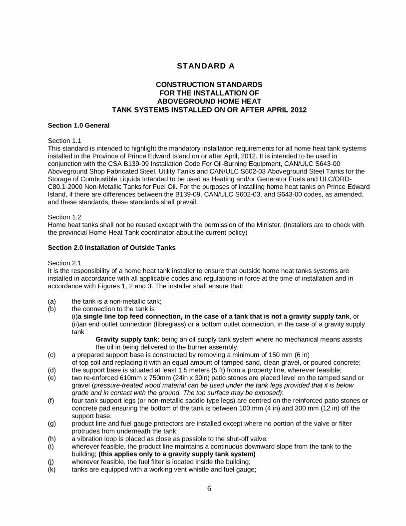
(m) piping and tubing is substantially supported and protected against physical damage; (n) two or more cross connected tanks are installed on a common poured cement pad; and (o) cross connected tanks are installed in accordance with section 14 of this standard. Figure 1. Installation Diagram for Outside Tanks A1 Concrete pad or reinforced patio stone A2 150 mm (6 in) tamped sand or clean gravel replacing 150mm (6 in) of topsoil A3 Horizontal vibration loop A4 Product line protector A5 Fuel gauge and gauge protector A6 Fill pipe, vent pipe, vent whistle
Gravity supply (bottom feed) Steel tanks only (Fiberglass tanks can be end feed)
This connection should be a bottom feed for steel tanks
7
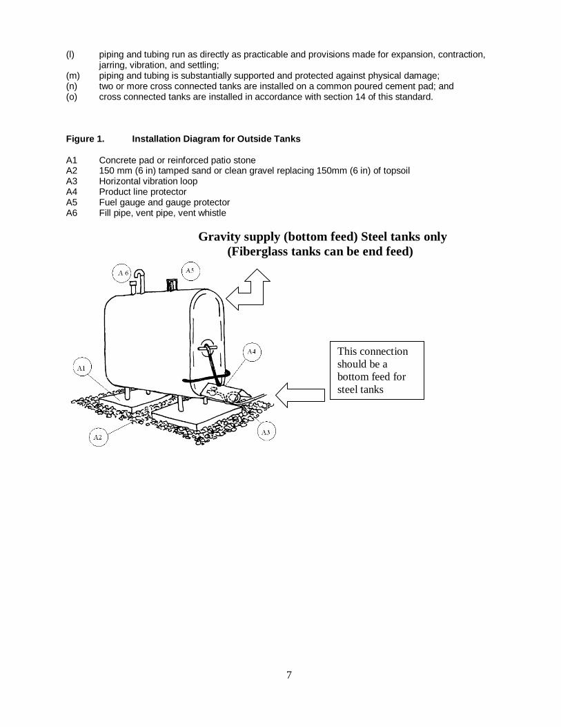
Typical top feed supply tank
8
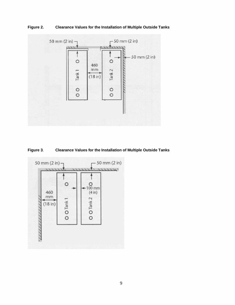
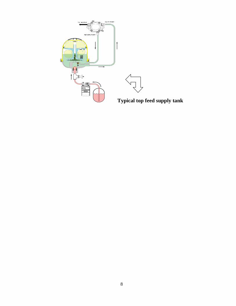
Figure 2. Clearance Values for the Installation of Multiple Outside Tanks
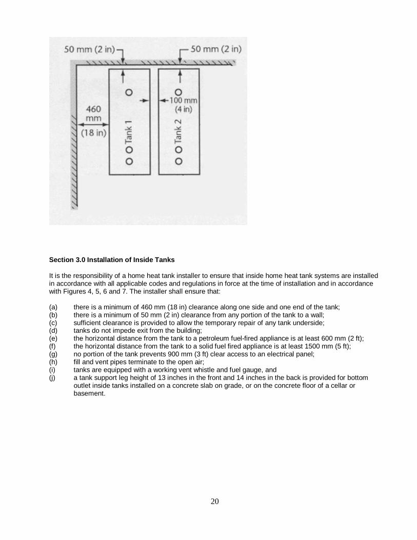
Figure 3. Clearance Values for the Installation of Multiple Outside Tanks
9
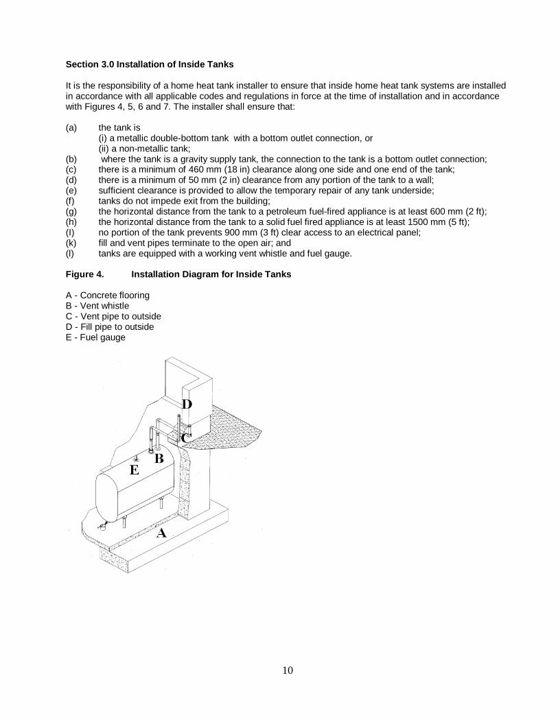
Section 3.0 Installation of Inside Tanks It is the responsibility of a home heat tank installer to ensure that inside home heat tank systems are installed in accordance with all applicable codes and regulations in force at the time of installation and in accordance with Figures 4, 5, 6 and 7. The installer shall ensure that: (a) the tank is
(i) a metallic double-bottom tank with a bottom outlet connection, or (ii) a non-metallic tank;
(b) where the tank is a gravity supply tank, the connection to the tank is a bottom outlet connection; (c) there is a minimum of 460 mm (18 in) clearance along one side and one end of the tank; (d) there is a minimum of 50 mm (2 in) clearance from any portion of the tank to a wall; (e) sufficient clearance is provided to allow the temporary repair of any tank underside; (f) tanks do not impede exit from the building; (g) the horizontal distance from the tank to a petroleum fuel-fired appliance is at least 600 mm (2 ft); (h) the horizontal distance from the tank to a solid fuel fired appliance is at least 1500 mm (5 ft); (I) no portion of the tank prevents 900 mm (3 ft) clear access to an electrical panel; (k) fill and vent pipes terminate to the open air; and (l) tanks are equipped with a working vent whistle and fuel gauge. Figure 4. Installation Diagram for Inside Tanks A - Concrete flooring B - Vent whistle C - Vent pipe to outside D - Fill pipe to outside E - Fuel gauge
10

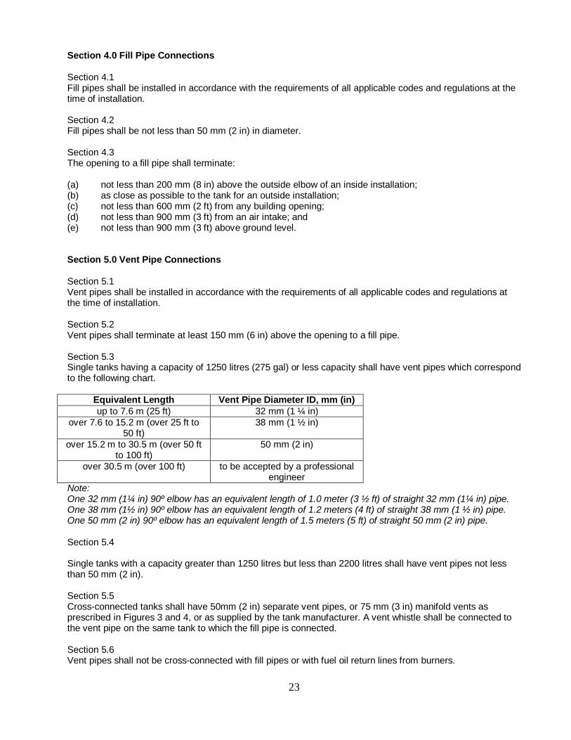
Figure 5. Clearance Values for the Installation of Multiple Inside Tanks
Figure 6. Clearance Values for the Installation of Multiple Inside Tanks
11
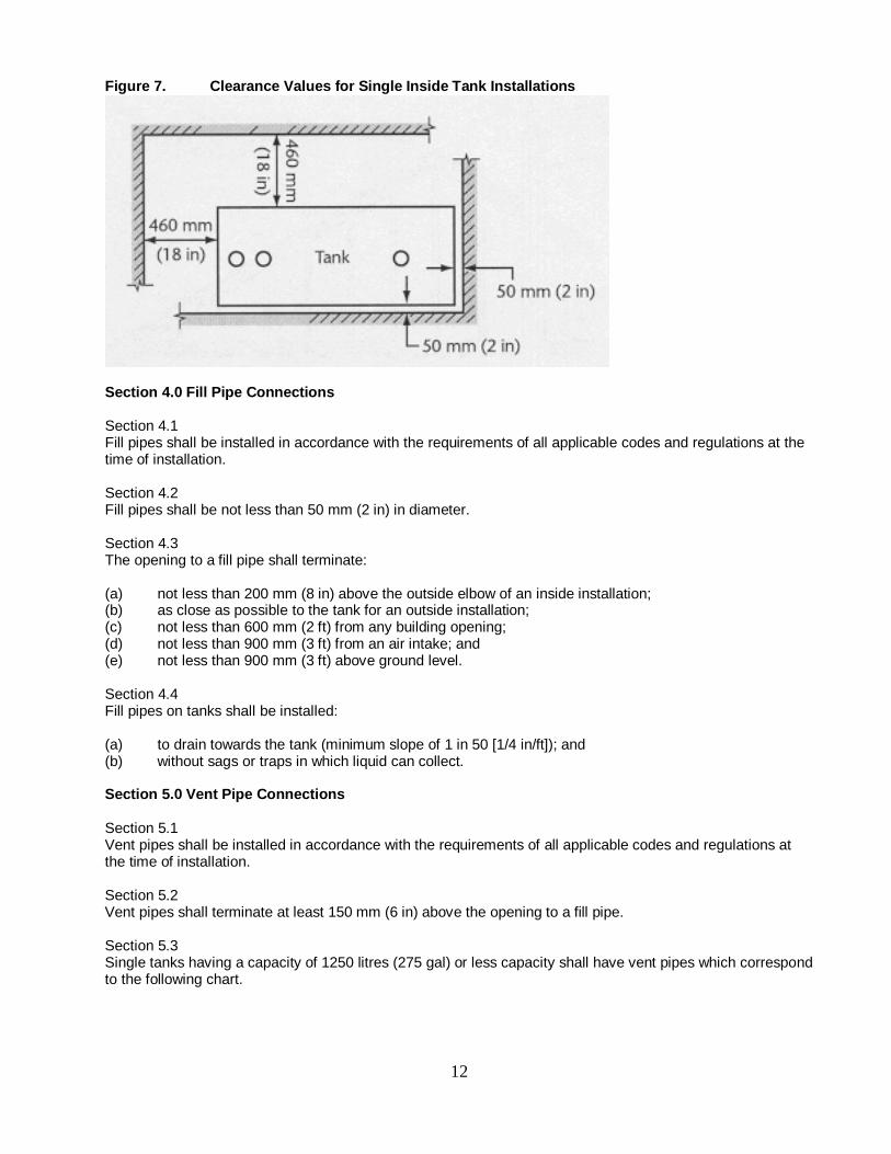
Figure 7. Clearance Values for Single Inside Tank Installations
Section 4.0 Fill Pipe Connections Section 4.1 Fill pipes shall be installed in accordance with the requirements of all applicable codes and regulations at the time of installation. Section 4.2 Fill pipes shall be not less than 50 mm (2 in) in diameter. Section 4.3 The opening to a fill pipe shall terminate: (a) not less than 200 mm (8 in) above the outside elbow of an inside installation; (b) as close as possible to the tank for an outside installation; (c) not less than 600 mm (2 ft) from any building opening; (d) not less than 900 mm (3 ft) from an air intake; and (e) not less than 900 mm (3 ft) above ground level. Section 4.4 Fill pipes on tanks shall be installed: (a) to drain towards the tank (minimum slope of 1 in 50 [1/4 in/ft]); and (b) without sags or traps in which liquid can collect. Section 5.0 Vent Pipe Connections Section 5.1 Vent pipes shall be installed in accordance with the requirements of all applicable codes and regulations at the time of installation. Section 5.2 Vent pipes shall terminate at least 150 mm (6 in) above the opening to a fill pipe. Section 5.3 Single tanks having a capacity of 1250 litres (275 gal) or less capacity shall have vent pipes which correspond to the following chart.
12
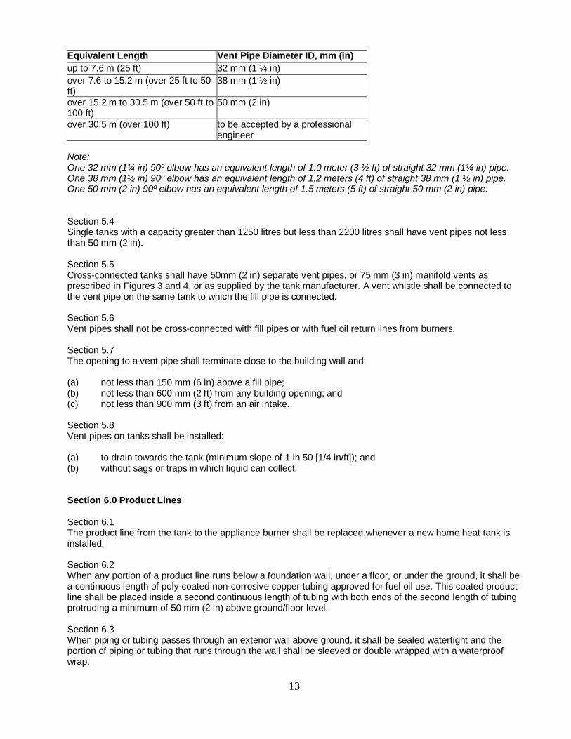
Equivalent Length Vent Pipe Diameter ID, mm (in) up to 7.6 m (25 ft) 32 mm (1 ¼ in) over 7.6 to 15.2 m (over 25 ft to 50 ft)
38 mm (1 ½ in)
over 15.2 m to 30.5 m (over 50 ft to 100 ft)
50 mm (2 in)
over 30.5 m (over 100 ft) to be accepted by a professional engineer
Note: One 32 mm (1¼ in) 90º elbow has an equivalent length of 1.0 meter (3 ½ ft) of straight 32 mm (1¼ in) pipe. One 38 mm (1½ in) 90º elbow has an equivalent length of 1.2 meters (4 ft) of straight 38 mm (1 ½ in) pipe. One 50 mm (2 in) 90º elbow has an equivalent length of 1.5 meters (5 ft) of straight 50 mm (2 in) pipe. Section 5.4 Single tanks with a capacity greater than 1250 litres but less than 2200 litres shall have vent pipes not less than 50 mm (2 in). Section 5.5 Cross-connected tanks shall have 50mm (2 in) separate vent pipes, or 75 mm (3 in) manifold vents as prescribed in Figures 3 and 4, or as supplied by the tank manufacturer. A vent whistle shall be connected to the vent pipe on the same tank to which the fill pipe is connected. Section 5.6 Vent pipes shall not be cross-connected with fill pipes or with fuel oil return lines from burners. Section 5.7 The opening to a vent pipe shall terminate close to the building wall and: (a) not less than 150 mm (6 in) above a fill pipe; (b) not less than 600 mm (2 ft) from any building opening; and (c) not less than 900 mm (3 ft) from an air intake. Section 5.8 Vent pipes on tanks shall be installed: (a) to drain towards the tank (minimum slope of 1 in 50 [1/4 in/ft]); and (b) without sags or traps in which liquid can collect. Section 6.0 Product Lines Section 6.1 The product line from the tank to the appliance burner shall be replaced whenever a new home heat tank is installed. Section 6.2 When any portion of a product line runs below a foundation wall, under a floor, or under the ground, it shall be a continuous length of poly-coated non-corrosive copper tubing approved for fuel oil use. This coated product line shall be placed inside a second continuous length of tubing with both ends of the second length of tubing protruding a minimum of 50 mm (2 in) above ground/floor level. Section 6.3 When piping or tubing passes through an exterior wall above ground, it shall be sealed watertight and the portion of piping or tubing that runs through the wall shall be sleeved or double wrapped with a waterproof wrap.
13
Section 6.4 When piping or tubing passes through an interior wall of masonry or concrete, the portion of piping or tubing that runs through the wall shall be sleeved or double wrapped with a waterproof wrap. Section 6.5 An unthreaded portion of a piping outlet shall extend at least 25 mm (1 in) through either a finished ceiling or a finished wall at least 50 mm (2 in) through a floor. Section 7.0 Testing of New or Replacement Tanks When installing a home heat tank system, the installer shall test the tank connections for leaks by means of a pneumatic test, or a hydrostatic test during first filling. Note: when a pneumatic test is successfully performed that the home heat tank installer must hang on the fill pipe a signed document by the licensed Home Heat Tank installer that indicates 1) who did the test, 2) the test pressure and length of test, 3) date of pressure test. 4) all joints were soaped tested.
The oil delivery person is not to deliver oil unless presented with successful pressure test documentations. Section 8.0 Piping and Tubing Section 8.1 All piping and tubing shall be new and shall be standard-weight wrought iron, steel, or brass pipe; or brass, copper, or steel tubing, or the equivalent with respect to strength, durability, and resistance to corrosion and temperature. Section 8.2 Fill or vent pipes shall be steel or galvanized construction. Galvanized pipes, except as fill or vent pipes on storage or supply tanks, shall not be used when exposed to heat or for conveying preheated fuel oil. Section 8.3 Flexible metal hose may be used when rigid connections are impracticable, or when required to reduce the effect of jarring or vibration. Such hose shall be of a type certified for the application and shall be installed strictly in accordance with the approval for the appliance. Section 8.4 Joints and connections shall be made with standard pipe fitting or by welding. Section 8.5 Cast iron fittings shall not be used. Section 8.6 A joint in seamless copper, brass, or steel tubing shall be made by means of a flare joint or approved fitting, or shall be brazed with a material having a melting point exceeding 540ºC (1000ºF). Section 8.7 Compression fittings shall not be used. Section 8.8 Threaded joints in the vent and fill piping shall be made fuel-oil tight using joint compound or polytetrafluorethylene tape approved for use with fuel oil. Section 9.0 Shut-off Valves A shut-off valve shall be installed in the fuel line as near as practicable to the supply tank, and at such other locations as may be required to avoid spillage during servicing. Shut-off valves shall:
14
(a) be of the manual type; (b) be readily accessible; (c) be installed to close against the supply of fuel oil; (d) be substantially protected against physical damage; (e) be certified for its intended use (f) meet the requirements of the following publications, as amended from time to time:
(i) ULC/ORD-C180 Liquid Level Gauges and Indicators for Fuel Oil and Lubricating Oil Tanks; (ii) CSA B140 Oil-Burning Equipment: General Requirements.
Section 10.0 Fuel Oil Filters A suitable fuel oil filter or strainer assembly shall be provided in the fuel supply line to the appliance or equipment, and shall be located inside the building where the appliance or equipment is located, wherever feasible. An installer who installs an oil filter canister shall ensure that the oil filter canister (a) is corrosion resistant; (b) bears a manufacturer’s label confirming that the oil filter canister is corrosion resistant, if the oil filter
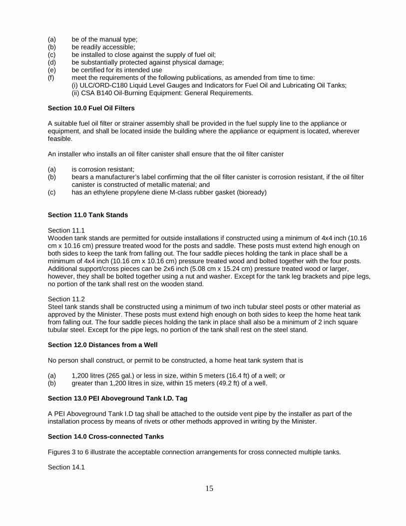
canister is constructed of metallic material; and (c) has an ethylene propylene diene M-class rubber gasket (bioready) Section 11.0 Tank Stands Section 11.1 Wooden tank stands are permitted for outside installations if constructed using a minimum of 4x4 inch (10.16 cm x 10.16 cm) pressure treated wood for the posts and saddle. These posts must extend high enough on both sides to keep the tank from falling out. The four saddle pieces holding the tank in place shall be a minimum of 4x4 inch (10.16 cm x 10.16 cm) pressure treated wood and bolted together with the four posts. Additional support/cross pieces can be 2x6 inch (5.08 cm x 15.24 cm) pressure treated wood or larger, however, they shall be bolted together using a nut and washer. Except for the tank leg brackets and pipe legs, no portion of the tank shall rest on the wooden stand. Section 11.2 Steel tank stands shall be constructed using a minimum of two inch tubular steel posts or other material as approved by the Minister. These posts must extend high enough on both sides to keep the home heat tank from falling out. The four saddle pieces holding the tank in place shall also be a minimum of 2 inch square tubular steel. Except for the pipe legs, no portion of the tank shall rest on the steel stand. Section 12.0 Distances from a Well No person shall construct, or permit to be constructed, a home heat tank system that is (a) 1,200 litres (265 gal.) or less in size, within 5 meters (16.4 ft) of a well; or (b) greater than 1,200 litres in size, within 15 meters (49.2 ft) of a well. Section 13.0 PEI Aboveground Tank I.D. Tag A PEI Aboveground Tank I.D tag shall be attached to the outside vent pipe by the installer as part of the installation process by means of rivets or other methods approved in writing by the Minister. Section 14.0 Cross-connected Tanks Figures 3 to 6 illustrate the acceptable connection arrangements for cross connected multiple tanks. Section 14.1
15
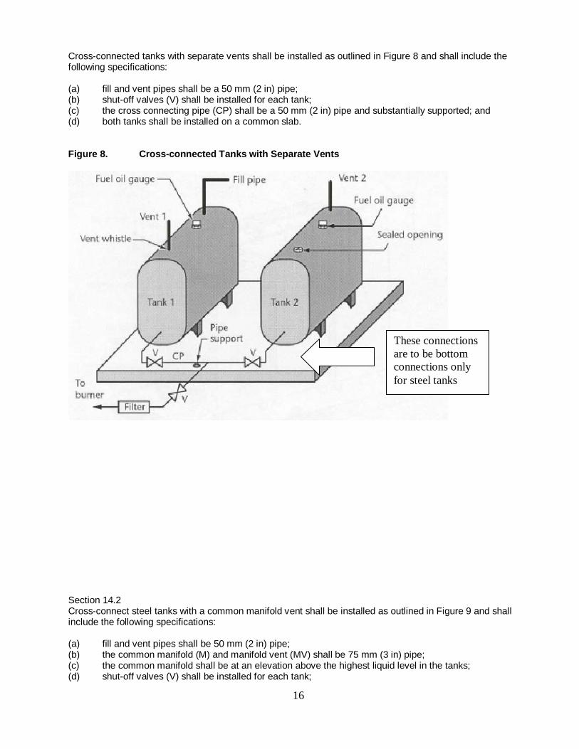
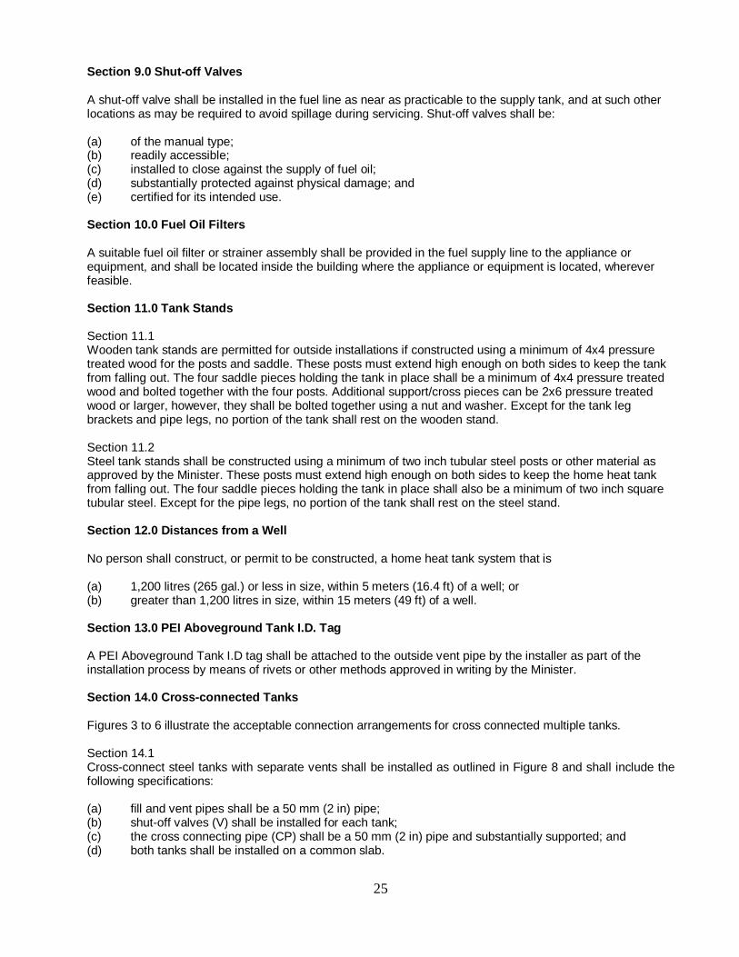
Cross-connected tanks with separate vents shall be installed as outlined in Figure 8 and shall include the following specifications: (a) fill and vent pipes shall be a 50 mm (2 in) pipe; (b) shut-off valves (V) shall be installed for each tank; (c) the cross connecting pipe (CP) shall be a 50 mm (2 in) pipe and substantially supported; and (d) both tanks shall be installed on a common slab. Figure 8. Cross-connected Tanks with Separate Vents
Section 14.2 Cross-connect steel tanks with a common manifold vent shall be installed as outlined in Figure 9 and shall include the following specifications: (a) fill and vent pipes shall be 50 mm (2 in) pipe; (b) the common manifold (M) and manifold vent (MV) shall be 75 mm (3 in) pipe; (c) the common manifold shall be at an elevation above the highest liquid level in the tanks; (d) shut-off valves (V) shall be installed for each tank;
These connections are to be bottom connections only for steel tanks
16
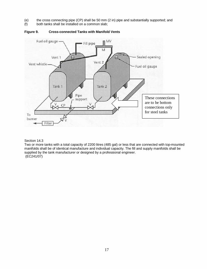
(e) the cross connecting pipe (CP) shall be 50 mm (2 in) pipe and substantially supported; and (f) both tanks shall be installed on a common slab; Figure 9. Cross-connected Tanks with Manifold Vents
Section 14.3 Two or more tanks with a total capacity of 2200 litres (485 gal) or less that are connected with top-mounted manifolds shall be of identical manufacture and individual capacity. The fill and supply manifolds shall be supplied by the tank manufacturer or designed by a professional engineer. (EC241/07)
These connections are to be bottom connections only for steel tanks
17

17
STANDARD B
CONSTRUCTION STANDARDS FOR THE INSTALLATION OF
ABOVEGROUND HOME HEAT TANK SYSTEMS INSTALLED AFTER MARCH 2004
AND PRIOR TO APRIL 2012 Section 1.0 General Section 1.1 This standard is intended to highlight the mandatory installation requirements for all home heat tank systems installed in the Province of Prince Edward Island after March 2004 and prior to April 2012. It is intended to be used in conjunction with the CSA B139-04 Installation Code For Oil-Burning Equipment, CAN/ULC S643-00 Aboveground Shop Fabricated Steel, Utility Tanks and CAN/ULC S602-03 Aboveground Steel Tanks for the Storage of Combustible Liquids Intended to be Used as Heating and/or Generator Fuels. For the purposes of installing home heat tanks on Prince Edward Island, any differences between the B139-04, CAN/ULC S602-03, and S643-00 codes and these standards, these standards shall prevail. Section 1.2 Home heat tanks shall not be reused except with the oral permission of the Minister. Section 2.0 Installation of Outside Tanks Section 2.1 It is the responsibility of a home heat tank installer to ensure that outside home heat tanks or systems are installed in accordance with all applicable codes and regulations in force at the time of installation and in accordance with Figures 1, 2 and 3. The installer shall ensure that: (a) a prepared support base is constructed by removing a minimum of 150 mm (6 in) of top soil and
replacing it with an equal amount of tamped sand, clean gravel, or poured concrete; (b) the support base is situated at least 1.5 meters (5 ft) from a property line, wherever feasible; (c) two re-enforced 610 mm x 750 mm (24 in x 30 in) patio stones are placed level on the tamped sand
or gravel (pressure-treated wood material can be used under the tank legs provided that it is below grade and in contact with the ground. The top surface may be exposed);
(d) four tank support legs are centred on the reinforced patio stones or concrete pad ensuring the bottom of the tank is between 100 mm (4 in) and 300 mm (12 in) off the support base;
(e) product line and fuel gauge protectors are installed except where no portion of the valve or filter protrudes from underneath the tank;
(f) a horizontal vibration loop is placed as close as possible to the shut-off valve; (g) wherever feasible, the product line maintains a continuous downward slope from the tank to the
building; (h) wherever feasible, the fuel filter is located inside the building; (i) tanks are equipped with a working vent whistle and fuel gauge; (j) piping and tubing run as directly as practicable and provisions made for expansion, contraction,
jarring, vibration, and settling; (k) piping and tubing is substantially supported and protected against physical damage; (l) two or more cross connected tanks are installed on a common poured cement pad; and (m) cross connected tanks are installed in accordance with section 14 of this standard.
18
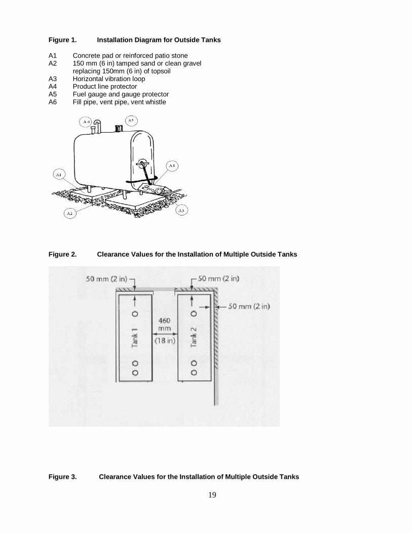
Figure 1. Installation Diagram for Outside Tanks A1 Concrete pad or reinforced patio stone A2 150 mm (6 in) tamped sand or clean gravel replacing 150mm (6 in) of topsoil A3 Horizontal vibration loop A4 Product line protector A5 Fuel gauge and gauge protector A6 Fill pipe, vent pipe, vent whistle
Figure 2. Clearance Values for the Installation of Multiple Outside Tanks
Figure 3. Clearance Values for the Installation of Multiple Outside Tanks
19
Section 3.0 Installation of Inside Tanks It is the responsibility of a home heat tank installer to ensure that inside home heat tank systems are installed in accordance with all applicable codes and regulations in force at the time of installation and in accordance with Figures 4, 5, 6 and 7. The installer shall ensure that: (a) there is a minimum of 460 mm (18 in) clearance along one side and one end of the tank; (b) there is a minimum of 50 mm (2 in) clearance from any portion of the tank to a wall; (c) sufficient clearance is provided to allow the temporary repair of any tank underside; (d) tanks do not impede exit from the building; (e) the horizontal distance from the tank to a petroleum fuel-fired appliance is at least 600 mm (2 ft); (f) the horizontal distance from the tank to a solid fuel fired appliance is at least 1500 mm (5 ft); (g) no portion of the tank prevents 900 mm (3 ft) clear access to an electrical panel; (h) fill and vent pipes terminate to the open air; (i) tanks are equipped with a working vent whistle and fuel gauge, and (j) a tank support leg height of 13 inches in the front and 14 inches in the back is provided for bottom
outlet inside tanks installed on a concrete slab on grade, or on the concrete floor of a cellar or basement.
20
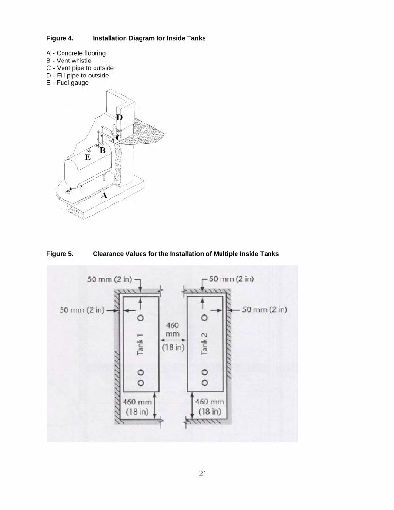
Figure 4. Installation Diagram for Inside Tanks A - Concrete flooring B - Vent whistle C - Vent pipe to outside D - Fill pipe to outside E - Fuel gauge
Figure 5. Clearance Values for the Installation of Multiple Inside Tanks
21

Figure 6. Clearance Values for the Installation of Multiple Inside Tanks
Figure 7. Clearance Values for Single Inside Tank Installations
22
Section 4.0 Fill Pipe Connections Section 4.1 Fill pipes shall be installed in accordance with the requirements of all applicable codes and regulations at the time of installation. Section 4.2 Fill pipes shall be not less than 50 mm (2 in) in diameter. Section 4.3 The opening to a fill pipe shall terminate: (a) not less than 200 mm (8 in) above the outside elbow of an inside installation; (b) as close as possible to the tank for an outside installation; (c) not less than 600 mm (2 ft) from any building opening; (d) not less than 900 mm (3 ft) from an air intake; and (e) not less than 900 mm (3 ft) above ground level. Section 5.0 Vent Pipe Connections Section 5.1 Vent pipes shall be installed in accordance with the requirements of all applicable codes and regulations at the time of installation. Section 5.2 Vent pipes shall terminate at least 150 mm (6 in) above the opening to a fill pipe. Section 5.3 Single tanks having a capacity of 1250 litres (275 gal) or less capacity shall have vent pipes which correspond to the following chart.
Equivalent Length Vent Pipe Diameter ID, mm (in) up to 7.6 m (25 ft) 32 mm (1 ¼ in)
over 7.6 to 15.2 m (over 25 ft to 50 ft)
38 mm (1 ½ in)
over 15.2 m to 30.5 m (over 50 ft to 100 ft)
50 mm (2 in)
over 30.5 m (over 100 ft) to be accepted by a professional engineer
Note: One 32 mm (1¼ in) 90º elbow has an equivalent length of 1.0 meter (3 ½ ft) of straight 32 mm (1¼ in) pipe. One 38 mm (1½ in) 90º elbow has an equivalent length of 1.2 meters (4 ft) of straight 38 mm (1 ½ in) pipe. One 50 mm (2 in) 90º elbow has an equivalent length of 1.5 meters (5 ft) of straight 50 mm (2 in) pipe. Section 5.4 Single tanks with a capacity greater than 1250 litres but less than 2200 litres shall have vent pipes not less than 50 mm (2 in). Section 5.5 Cross-connected tanks shall have 50mm (2 in) separate vent pipes, or 75 mm (3 in) manifold vents as prescribed in Figures 3 and 4, or as supplied by the tank manufacturer. A vent whistle shall be connected to the vent pipe on the same tank to which the fill pipe is connected. Section 5.6 Vent pipes shall not be cross-connected with fill pipes or with fuel oil return lines from burners.
23
Section 5.7 The opening to a vent pipe shall terminate close to the building wall and: (a) not less than 150 mm (6 in) above a fill pipe; (b) not less than 600 mm (2 ft) from any building opening; and (c) not less than 900 mm (3 ft) from an air intake. Section 6.0 Product Lines Section 6.1 The product line from the tank to the appliance burner shall be replaced whenever a new home heat tank is installed. Section 6.2 When any portion of a product line runs below a foundation wall, under a floor, or under the ground, it shall be a continuous length of poly-coated non-corrosive copper tubing approved for fuel oil use. This coated product line shall be placed inside a second continuous length of tubing with both ends of the second length of tubing protruding a minimum of 50 mm (2 in) above ground/floor level. Section 7.0 Testing of New or Replacement Tanks When installing a single-wall home heat tank system, the installer shall test the tank connections for leaks by means of a pneumatic test, or a hydrostatic test during first filling. Section 8.0 Piping and Tubing Section 8.1 All piping and tubing shall be new and shall be standard-weight wrought iron, steel, or brass pipe; or brass, copper, or steel tubing. Section 8.2 Fill or vent pipes shall be steel or galvanized construction. Galvanized pipes, except as fill or vent pipes on storage or supply tanks, shall not be used when exposed to heat or for conveying preheated fuel oil. Section 8.3 Flexible metal hose may be used when rigid connections are impracticable, or when required to reduce the effect of jarring or vibration. Such hose shall be of a type certified for the application and shall be installed strictly in accordance with the approval for the appliance. Section 8.4 Joints and connections shall be made with standard pipe fitting or by welding. Section 8.5 Cast iron fittings shall not be used. Section 8.6 A joint in seamless copper, brass, or steel tubing shall be made by means of a flare joint or approved fitting, or shall be brazed with a material having a melting point exceeding 540ºC (1000ºF). Section 8.7 Compression fittings shall not be used. Section 8.8 Threaded joints in the vent and fill piping shall be made fuel-oil tight using joint compound or polytetrafluorethylene tape approved for use with fuel oil.
24
Section 9.0 Shut-off Valves A shut-off valve shall be installed in the fuel line as near as practicable to the supply tank, and at such other locations as may be required to avoid spillage during servicing. Shut-off valves shall be: (a) of the manual type; (b) readily accessible; (c) installed to close against the supply of fuel oil; (d) substantially protected against physical damage; and (e) certified for its intended use. Section 10.0 Fuel Oil Filters A suitable fuel oil filter or strainer assembly shall be provided in the fuel supply line to the appliance or equipment, and shall be located inside the building where the appliance or equipment is located, wherever feasible. Section 11.0 Tank Stands Section 11.1 Wooden tank stands are permitted for outside installations if constructed using a minimum of 4x4 pressure treated wood for the posts and saddle. These posts must extend high enough on both sides to keep the tank from falling out. The four saddle pieces holding the tank in place shall be a minimum of 4x4 pressure treated wood and bolted together with the four posts. Additional support/cross pieces can be 2x6 pressure treated wood or larger, however, they shall be bolted together using a nut and washer. Except for the tank leg brackets and pipe legs, no portion of the tank shall rest on the wooden stand. Section 11.2 Steel tank stands shall be constructed using a minimum of two inch tubular steel posts or other material as approved by the Minister. These posts must extend high enough on both sides to keep the home heat tank from falling out. The four saddle pieces holding the tank in place shall also be a minimum of two inch square tubular steel. Except for the pipe legs, no portion of the tank shall rest on the steel stand. Section 12.0 Distances from a Well No person shall construct, or permit to be constructed, a home heat tank system that is (a) 1,200 litres (265 gal.) or less in size, within 5 meters (16.4 ft) of a well; or (b) greater than 1,200 litres in size, within 15 meters (49 ft) of a well. Section 13.0 PEI Aboveground Tank I.D. Tag A PEI Aboveground Tank I.D tag shall be attached to the outside vent pipe by the installer as part of the installation process by means of rivets or other methods approved in writing by the Minister. Section 14.0 Cross-connected Tanks Figures 3 to 6 illustrate the acceptable connection arrangements for cross connected multiple tanks. Section 14.1 Cross-connect steel tanks with separate vents shall be installed as outlined in Figure 8 and shall include the following specifications: (a) fill and vent pipes shall be a 50 mm (2 in) pipe; (b) shut-off valves (V) shall be installed for each tank; (c) the cross connecting pipe (CP) shall be a 50 mm (2 in) pipe and substantially supported; and (d) both tanks shall be installed on a common slab.
25
Figure 8. Cross-connected Tanks with Separate Vents
Section 14.2 Cross-connect steel tanks with a common manifold vent shall be installed as outlined in Figure 9 and shall include the following specifications: (a) fill and vent pipes shall be 50 mm (2 in) pipe; (b) the common manifold (M) and manifold vent (MV) shall be 75 mm (3 in) pipe; (c) the common manifold shall be at an elevation above the highest liquid level in the tanks; (d) shut-off valves (V) shall be installed for each tank; (e) the cross connecting pipe (CP) shall be 50 mm (2 in) pipe and substantially supported; and (f) both tanks shall be installed on a common slab;
26

Figure 9. Cross-connected Tanks with Manifold Vents
Section 14.3 Two or more tanks with a total capacity of 2200 litres (1100 gal) or less that are connected with top-mounted manifolds shall be of identical manufacture and individual capacity. The fill and supply manifolds shall be supplied by the tank manufacturer or designed by a professional engineer.
27
STANDARD C
STANDARD FOR THE INSPECTION AND TAGGING OF HOME HEAT TANK SYSTEMS WITH A TOTAL
CAPACITY OF 2,200 LITRES OR LESS FOR HOME HEAT TANKS INSTALLED PRIOR TO MARCH 2004
Section 1.0 General This standard provides a general overview of the inspection and tagging requirements for home heat tank systems installed prior to March 1, 2004 in the Province of Prince Edward Island. It is not intended to be all inclusive and should be used as a general guide in conjunction with applicable codes and training manuals. Home heat tank systems installed after March 2004 must be inspected and tagged in accordance with the requirements of Schedule B. This standard is intended to highlight the mandatory inspection requirements for all home heat tanks installed in the Province of Prince Edward Island prior to March 1, 2004. It is intended to be used in conjunction with the applicable versions of CSA B139 Installation Code For Oil-Burning Equipment, CAN/ULC S643 Aboveground Shop Fabricated Steel, Utility Tanks and CAN/ULC S602 Aboveground Steel Tanks for the Storage of Combustible Liquids Intended to be Used as Heating and/or Generator Fuels. The specific version of the codes will depend upon when the tank was originally installed. For example, if the tank was installed in accordance with the CSA B139-00 code, it should also be inspected in accordance with that code. For the purposes of inspecting home heat tanks on Prince Edward Island, any differences between the B139, CAN/ULC S602, and CAN/ULC S643 codes and these standards, these standards shall be considered paramount. Section 2.0 Installation of Outside Tanks Section 2.1 Outside home heat tank systems shall include: (a) a prepared support base constructed by removing a minimum of 150 mm (6 in) of top soil and
replacing it with an equal amount of tamped sand, crushed gravel, or poured concrete; (b) two reinforced patio stones placed level on top of the gravel or tamped sand; (Note: Reinforced patio
stones without the gravel, or 4x4 and larger pressure-treated or creosote timbers are permitted to be used if they are level and in good condition. Individual wooden or cement blocks shall not be used as part of an outside installation);
(c) four tank support legs centred on the two re-enforced patio stones or concrete pad ensuring the bottom of the tank is at least 100 mm (4 in) off the support base. Tank legs longer than 300 mm (12 in) must be substantially braced;
(d) a horizontal vibration loop placed in the product line as close as possible to the shut-off valve; (e) a fuel filter connected to the product line and located inside the building, wherever feasible; (f) a product line protector; (g) a working vent whistle attached to a 37 mm (1 ¼ in) vent pipe; (h) a 50 mm (2 in) fill pipe complete with a tight metal cover designed to discourage tampering; (i) piping and tubing which is substantially supported and protected against physical damage; and (j) a common poured cement pad for two or more cross-connected tanks.
28
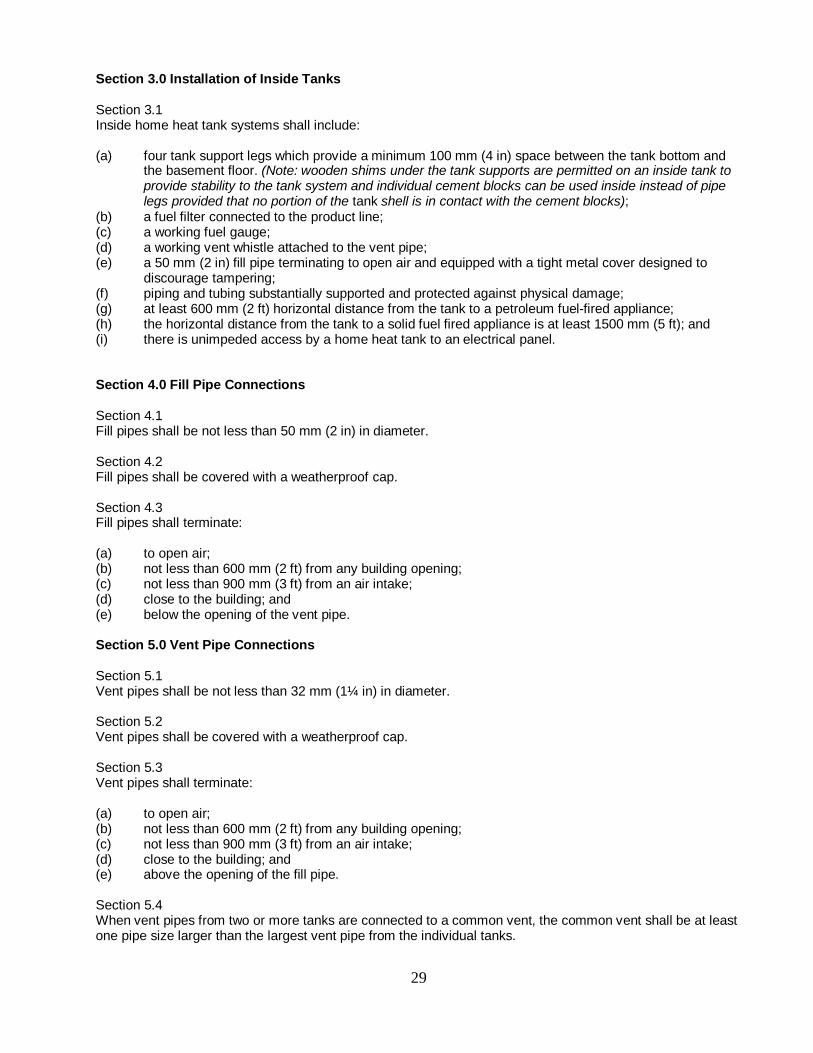
Section 3.0 Installation of Inside Tanks Section 3.1 Inside home heat tank systems shall include: (a) four tank support legs which provide a minimum 100 mm (4 in) space between the tank bottom and
the basement floor. (Note: wooden shims under the tank supports are permitted on an inside tank to provide stability to the tank system and individual cement blocks can be used inside instead of pipe legs provided that no portion of the tank shell is in contact with the cement blocks);
(b) a fuel filter connected to the product line; (c) a working fuel gauge; (d) a working vent whistle attached to the vent pipe; (e) a 50 mm (2 in) fill pipe terminating to open air and equipped with a tight metal cover designed to
discourage tampering; (f) piping and tubing substantially supported and protected against physical damage; (g) at least 600 mm (2 ft) horizontal distance from the tank to a petroleum fuel-fired appliance; (h) the horizontal distance from the tank to a solid fuel fired appliance is at least 1500 mm (5 ft); and (i) there is unimpeded access by a home heat tank to an electrical panel. Section 4.0 Fill Pipe Connections Section 4.1 Fill pipes shall be not less than 50 mm (2 in) in diameter. Section 4.2 Fill pipes shall be covered with a weatherproof cap. Section 4.3 Fill pipes shall terminate: (a) to open air; (b) not less than 600 mm (2 ft) from any building opening; (c) not less than 900 mm (3 ft) from an air intake; (d) close to the building; and (e) below the opening of the vent pipe. Section 5.0 Vent Pipe Connections Section 5.1 Vent pipes shall be not less than 32 mm (1¼ in) in diameter. Section 5.2 Vent pipes shall be covered with a weatherproof cap. Section 5.3 Vent pipes shall terminate: (a) to open air; (b) not less than 600 mm (2 ft) from any building opening; (c) not less than 900 mm (3 ft) from an air intake; (d) close to the building; and (e) above the opening of the fill pipe. Section 5.4 When vent pipes from two or more tanks are connected to a common vent, the common vent shall be at least one pipe size larger than the largest vent pipe from the individual tanks.
29
Section 5.5 Vent pipes shall not be cross-connected with fill pipes or with fuel oil return lines from burners. Section 6.0 Product Lines Section 6.1 When any portion of a product line runs below a foundation wall, under a floor, or under the ground, it shall: (a) if installed prior to April 1, 2000, be a continuous length of plain or poly coated copper product line
inside a continuous run of tubing which protrudes a minimum of 50 mm (2 in) above the ground or basement floor; or
(b) if installed after April 1, 2000, be a continuous length of poly coated copper product line inside a continuous run of tubing which protrudes a minimum of 50 mm (2 in) above the ground or basement floor.
Section 7.0 Piping and Tubing Section 7.1 Fill or vent pipes shall be steel or galvanized construction. Galvanized pipes, except as fill or vent pipes on or supply tanks, shall not be used when exposed to heat or for conveying preheated fuel oil. Section 7.2 Flexible metal hose may be used when rigid connections are impracticable, or when required to reduce the effect of jarring or vibration. Such hose shall be of a type certified for the application and shall be installed strictly in accordance with the approval for the appliance. Section 7.3 Cast iron or compression fittings shall not be used. Section 7.4 A joint in seamless copper, brass, or steel tubing shall be made by means of a flare joint or approved fitting, or shall be brazed with a material having a melting point exceeding 540ºC (1000ºF). Section 7.5 Threaded joints shall be made fuel-oil tight. Section 8.0 Shut-off Valves A shut-off valve shall be installed in the fuel line as near as practicable to the exit from the supply tank, and at such other locations as may be required to avoid spillage during servicing. Section 9.0 Fuel Oil Filters A suitable fuel oil filter or strainer assembly shall be provided in the fuel supply line to the oil burner, and shall be located inside the building wherever feasible. Section 10.0 Tank Stands Section 10.1 Wooden oil tank stands are permitted for outside installations if constructed using a minimum of 4x4 pressure treated wood for the posts and saddle. These posts must extend high enough on both sides to keep the tank from falling out. The four saddle pieces holding the tank in place shall be a minimum of 4x4 pressure treated wood and bolted together with the four posts. Additional support/cross pieces can be 2x6 pressure treated wood or larger, however, they shall be bolted together using a nut and washer. Except for the leg brackets and pipe legs, no portion of the tank shall rest on the wooden stand.
30
Section 10.2 Steel tank stands shall be constructed using a minimum of two inch tubular steel posts or other material as approved by the Department. These posts must extend high enough on both sides to keep the home heat tank from falling out. The four saddle pieces holding the tank in place shall also be a minimum of two inch square tubular steel. Except for the pipe legs, no portion of the tank shall rest on the steel stand. Section 11.0 PEI Aboveground Tank I.D. Tag PEI Aboveground Tank I.D tags attached to the outside vent pipe as part of the inspection process shall be attached by means of rivets or other method approved in writing by the Minister.
31

APPENDIX A
Identification Tag
Registration Tag For double bottom tanks or non-metallic tanks
PEI ABOVEGROUND
OIL TANK I.D. TAG
XXXXXX
20__
PEI ABOVEGROUND
OIL TANK I.D. TAG
XXXXXX
20__
PEI ABOVEGROUND
OIL TANK I.D. TAG
XXXXXX
PEI ABOVEGROUND
OIL TANK I.D. TAG
XXXXXX
20__
32

33

APPENDIX B
Mandatory Replacement Years for Home Heat Tanks (calculated from the year of manufacture)
Steel Thickness Outlet/Connecti
on Type Mandatory Replacement
Year Non-metallic tanks Not applicable No mandatory
replacement year Double-bottom metallic tank
Not applicable No mandatory replacement year
Metallic tank with nominal steel
thickness of 2.0 mm*
Tank end or top burner
connection
15 years from year of tank manufacture
Metallic tank with nominal steel
thickness of 2.0 mm*
Bottom outlet burner
connection
20 years from year of tank manufacture
Metallic tank with nominal steel
thickness of 2.3 mm**
Tank end or top burner
connection
20 years from year of tank manufacture
Metallic tank with nominal steel
thickness of 2.3 mm**
Bottom outlet burner
connection
25 years from year of tank manufacture
*The permissible minimum steel thickness of a 2.0 mm (14 gauge) tank is between 1.80 mm and 2.09 mm.
**The permissible minimum steel thickness of a 2.3 mm (12 gauge) tank is 2.10 mm and above.
34

35
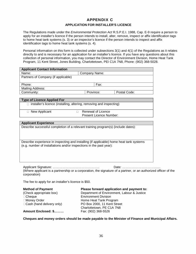
APPENDIX C APPLICATION FOR INSTALLER’S LICENCE
The Regulations made under the Environmental Protection Act R.S.P.E.I. 1988, Cap. E-9 require a person to apply for an installer’s licence if the person intends to install, alter, remove, inspect or affix identification tags to home heat tank systems (s. 3) or an inspector’s licence if the person intends to inspect and affix identification tags to home heat tank systems (s. 4). Personal information on this form is collected under subsections 3(1) and 4(1) of the Regulations as it relates directly to and is necessary for an application for an installer’s licence. If you have any questions about this collection of personal information, you may contact the Director of Environment Division, Home Heat Tank Program, 11 Kent Street, Jones Building, Charlottetown, PEI C1A 7N8, Phone: (902) 368-5028.
Applicant Contact Information Name: Company Name: Partners of Company (if applicable) Phone: Fax: Mailing Address: Community: Province: Postal Code:
Type of Licence Applied For installer’s licence (installing, altering, removing and inspecting) New Applicant Renewal of Licence Present Licence Number:
Applicant Experience Describe successful completion of a relevant training program(s) (include dates): Describe experience in inspecting and installing (if applicable) home heat tank systems (e.g. number of installations and/or inspections in the past year):
Applicant Signature: …………………………………….. Date: …………………………....... (Where applicant is a partnership or a corporation, the signature of a partner, or an authorized officer of the corporation) The fee to apply for an installer’s licence is $50. Method of Payment Please forward application and payment to: (Check appropriate box) Department of Environment, Labour & Justice �Cheque Environment Division �Money Order Home Heat Tank Program �Cash (hand delivery only) PO Box 2000, 11 Kent Street Charlottetown, PE C1A 7N8 Amount Enclosed: $……… Fax: (902) 368-5526 Cheques and money orders should be made payable to the Minister of Finance and Municipal Affairs.
36

37
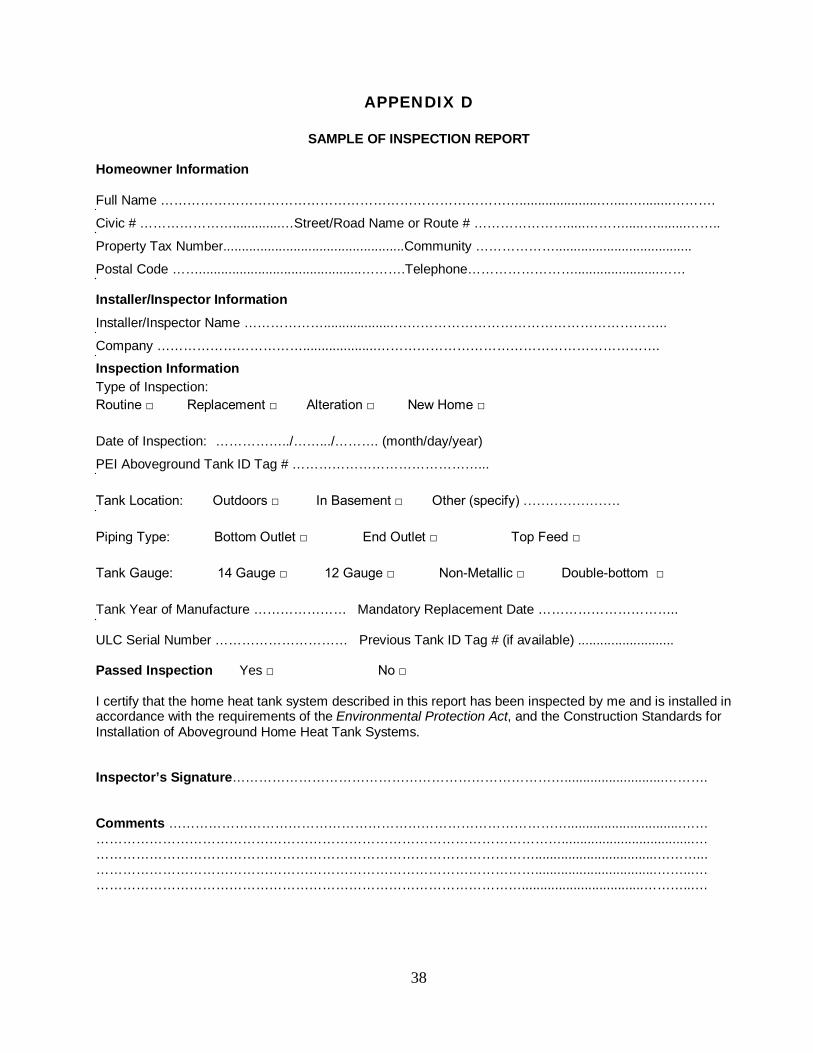
APPENDIX D
SAMPLE OF INSPECTION REPORT Homeowner Information Full Name ………………………………………………………………………......................…....…........……….
Civic # ………………….............…Street/Road Name or Route # ………………….....……….....…........……..
Property Tax Number.................................................Community ……………….....................................
Postal Code ……............................................……….Telephone…………………….......................…… Installer/Inspector Information
Installer/Inspector Name ………………...................……………………………………………………..
Company ……………………………....................………………………………………………………. Inspection Information Type of Inspection: Routine □ Replacement □ Alteration □ New Home □ Date of Inspection: ……………../…….../………. (month/day/year)
PEI Aboveground Tank ID Tag # ……………………………………... Tank Location: Outdoors □ In Basement □ Other (specify) …………………. Piping Type: Bottom Outlet □ End Outlet □ Top Feed □ Tank Gauge: 14 Gauge □ 12 Gauge □ Non-Metallic □ Double-bottom □ Tank Year of Manufacture ………………… Mandatory Replacement Date ………………………….. ULC Serial Number ………………………… Previous Tank ID Tag # (if available) .......................... Passed Inspection Yes □ No □ I certify that the home heat tank system described in this report has been inspected by me and is installed in accordance with the requirements of the Environmental Protection Act, and the Construction Standards for Installation of Aboveground Home Heat Tank Systems. Inspector’s Signature…………………………………………………………………...........................………. Comments ………………………………………………………………………………...............................…… ……………………………………………………………………………………………....................................… ……………………………………………………………………………………….................................………... ……………………………………………………………………………………….................................……...… …………………………………………………………………………………….................................………...…
38