home automation using esp8266 - home | · home automation using esp8266 madhurai das department of...
TRANSCRIPT

Transactions on Machine Design Volume 6 Number 2 August 2018 47
Home Automation Using ESP8266
Madhurai DasDepartment of Computer Science and EngineeringSRM University, RamapuramTamil Nadu, [email protected]
ABSTRACT: World’s demand for electricity had grown 85% between 2010 and 2017 this increase is more than today’s totaluse of electricity in India, USA, Japan, Australia combined. We can’t decrease the electricity growth rate but we can lessen theamount of electricity wasted each year by turning off our home appliances when not in use. This project presents a design andprototype of Home Automation system that will use ESP8266 Wi-Fi module as a network provider in connecting with otherappliances. The proposed system has two main components. The first main part is Arduino, which controls and manages inputof Wi-Fi module. The other main component is Wi-Fi module through Wi-Fi module a web server can be added to the modulewhich will help in controlling of devices over Internet. One server can manage many hardware interface modules as long asit exists on Wi-Fi network coverage. It supports a wide range of home automation devices like power management components,and security components. We want to make this automation system centralized and artificially intelligent. Further we willconnect the specific home to our database and it can be accessed from anywhere through a specific IP address or website.
Keywords: Automation, Arduino, ESP, Relay
Received: 1 May 2018, Revised 219 May 2018, Accepted 8 June 2018
© 2018 DLINE. All Rights Reserved
DOI: 10.6025/tmd/2018/6/2/47-56
1. Introduction
Home automation is also named as domestics or Smart home .It involves the control and automation of lighting, heating,ventilation, air conditioning and security, as well as home appliances. Wi-Fi is often used for remote monitoring and control.Home devices, when remotely monitored and controlled via Internet is a part of Internet of things. Modern systems generallyconsists of switches and sensors connected to a central hub called a gateway from which the system is controlled with a userinterface that isinteracted either with a mobile phone software ,tablet, computers or a web interface ,often but not always viainternet cloud services. World’s demand for electricity had grown 85% between 2010 and 2017 this increase is more than today’s
Transactions on Machine Design Volume 6 Number 2 August 2018 48
year by turning off our home appliances when not in use. World’s demand for electricity had grown 85% between 2010 and 2017this increase is more than today’s total use of electricity in India, USA, Japan, Australia combined. We can’t decrease theelectricity growth rate but we can lessen the amount of electricity wasted each year by turning off our home appliances when notin use. Unlike most of available home automation system in the market the proposed system is scalable that one server canmanage many hardware interface modules as long as it exists on Wi-Fi network coverage. System supports a wide range of homeautomation devices like power management components, and security components.
2. System Architeture
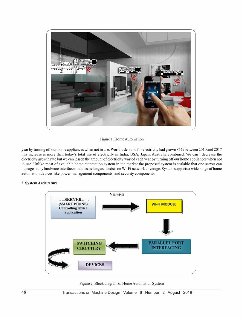
Figure 1. Home Automation
Figure 2. Block diagram of Home Automation System
Via wi-fi

Transactions on Machine Design Volume 6 Number 2 August 2018 49
The flowchart explains the home automation system. The controlling device will be connected with the Wi-Fi module throughhotspot created by the module (figure 2). The module will be connected with the microcontroller .The controller will give therequired command to the relay board and the relay board acts as switch between the circuit. The appliances will be connectedwith the relay board. Now, the appliances can be controlled using internet of things.
3. Literature Survey
3.1 Review of Related LiteratureWhen people think about home automation, most of them may imagine living in a smart home: One remote controller for everyhousehold appliance, cooking the rice automatically, starting air conditioner automatically, heating water for bath automaticallyand shading the window automatically during night. To some extent home automation equals to smart home. They both bringout smart living condition and make our life more convenient and fast. Early home automation began with labor-saving machines.Self-contained electric or gas powered home appliance became viable in the 1900s with the introduction of electric powerdistribution led to the introduction of washing machine (1904), water heater (1889),refrigerator, sewing machines, dishwashersand clothes dryers. As per our survey currently there exists system neither at cheaper rates nor easy to handle. Various systemsare hard to install, difficult to use and maintain. Current systems are generally proprietary, closed and not very user friendlyBased on Arduino or GSM or low cost home security system and home automation system.
3.2 Review of Foreign StudyIn their paper, Tan, Lee and Soh (2002) proposed the development of an Internet-based system to allow monitoring of importantprocess variables from a distributed control system (DCS). This paper proposes hardware and software design considerationswhich enable the user to access the process variables on the DCS, remotely and effectively rent designations.
Potamitis, Georgila, Fakotakis, and Kokkinos’s, G. (2003) suggested the use of speech to interact remotely with the homeappliances to perform a particular action on behalf of the user. The approach is inclined for people with disability to perform real-life operations at home by directing appliances through speech. Voice separation strategy is selected to take appropriatedecision by speech recognition.
In the year 2006, S. M. AnamulHaque,S. M. Kamruzzaman and Md. Ashraful Islam proposed a system entitled “A System forSmart-Home Control of Appliances Based on Time and Speech Interaction” that controls the home appliances using thepersonal computer. This system is developed by using the Visual Basic 6.0 as programming language and Microsoft voiceengine tools for speech recognition purpose. Appliances can be either controlled by timer or by voice command.
Jawarkar, Ahmed, Ladhake, and Thakare (2008) propose remote monitoring through mobile phone involving the use of spokencommands. The spoken commands are generated and sent in the form of text SMS to the control system and then themicrocontroller on the basis of SMS takes a decision of a particular task.
Prof. Era Johri Dept. Of Information and Technology K.J.Somaiya College of Engineering VIDYAVIHAR, MUMBAI in (2001)have successfully completed the project on “Remote Controlled Home Automation”.
4. Hardware
4.1 ArduinoArduino is an open source computer hardware and software company, project and user community that designs and manufacturessingle board microcontroller’s kits for building digital devices and interactive objects that can sense control object in world.Arduino board design use a variety of microprocessor and controller .The board are equipped with sets of digital and analoginput/output (I/O) pins that may be interfaced to various expansion boards and other circuits. The board features serialcommunication interface, including universal serial bus (USB) on some models, which are also used for loading program frompersonal computers. The microcontroller are typically programmed using a dialect feature from the programming language C&C++.
The Arduino Mega is a microcontroller board based on the ATmega1280 (datasheet). It has 54 digital input/output pins (of which14 can be used as PWM outputs), 16 analog inputs, 4 UARTs (hardware serial ports), a 16 MHz crystal oscillator, a USBconnection, a power jack, an ICSP header, and a reset button Table 1. It contains everything needed to support the microcontroller;

Transactions on Machine Design Volume 6 Number 2 August 2018 50
Figure 3. Arduino Board
simply connect it to a computer with a USB cable or power it with a AC-to-DC adapter or battery to get started. The Mega iscompatible with most shields designed for the Arduino Duemilanove or Diecimila.
S. No Operation Description
1 Operating Voltage 5V
2 Input Voltage (recommended) 7-12V
3 Input Voltage (limit) 6-20V
4 Digital I/O Pins 14 (of which 6 provide PWM output)
5 PWM Digital I/O Pins 6
6 Analog Input pins 6
7 DC Current per I/O Pin 20 Ma
8 DC Current for 3.3V Pin 50 Ma
9 Flash Memory 32 KB (A Tmega 328P) of which 0.5KB used by boot loader
10 SRAM 2 KB (A Tmega 328P)
11 EEPROM 1 KB (A Tmega 328P)
12 Clock Speed 16 MHz
13 LED BUILTIN 13
14 Length 68.6 mm
15 Weight 53.4 mm
Table 1. Pin explanation of Arduino

Transactions on Machine Design Volume 6 Number 2 August 2018 51
Arduino UNO is a microcontroller board based on the ATmega328P (datasheet). It has 14 digital input/output pins (of which 6can be used as PWM outputs), 6 analog inputs, a 16 MHz quartz crystal, a USB connection, a power jack, an ICSP header anda reset button. It contains everything needed to support the microcontroller; simply connect it to a computer with a USB cableor power it with a AC-to-DC adapter or battery to get started... You can tinker with your UNO without worrying too much aboutdoing something wrong, worst case scenario you can replace the chip for a few dollars and start over again.
“Uno” means one in Italian and was chosen to mark the release of Arduino Software (IDE) 1.0. The Uno board and version 1.0of Arduino Software ( IDE) were the reference versions of Arduino, now evolved to newer releases. The Uno board is the firstin a series of USB Arduino boards, and the reference model for the Arduino platform; for an extensive list of current, past oroutdated boards see the Arduino index of boards.
4.2 ESP8266 Wifi ModuleThe ESP8266 is a low cost Wi-Fi chip with full TCP/IP stack and microcontroller unit. This small module allows microcontrollerto connect to a Wi-Fi network and make simple TCP/IP connection using Hayes style commands, The ESP8266 with 1MiB ofbuilt in flash, allowing for single chip device capable of connecting to Wi-Fi. Figure 4 shows theESP8266 module structure.
Figure 4. ESP8266 Wifi Module
The various Features of ESP8266 WIFI MODULE are as follows: -
• Processor: L106 32-bit Reduced instruction set computer processor core bsed on Tensilica Xtensa Diamond Standard 106micro running at 80 MHZ*.
• 64 KiB of instrution RAM, 96 KiB of data RAM.
• External QSPI flash: 512 KiB to 4MiB.
• WPA/WPA2 authentication, or open networks.
• 16 General purpose input/output pins.

Transactions on Machine Design Volume 6 Number 2 August 2018 52
Figure 5. PIN Diagram explanation of ESP8266
• Serial Peripheral Interface Bus.
• Inter- Integrated circuit.
• Inter-IC sound interface with sharing pins with general purpose input output pins.
• 10 bits Analog to digital converter.
Name Type Function
VCC Power Power 3.0-3.6V
GND Power Ground
RESET Input External reset signal
ADC(TOUT) 0-1v Input ADC pin analog input
CH_PD chip Input Chip Enable High: on, Works properly
GIPO0(FLASH) Output Input/Output General purpose input If low while Takes chip into serialprogrammimg mode
GIPO1(TX) Serial Input/Output General purpose IO and RXd
GIPO3(RX) Serial Input/Output General purpose IO and RXd
GIPO4 Input/Output General purpose IO
GIPO5 Input/Output General purpose IO
GIPO12 Input/Output General purpose IO
Table 2. PIN Diagram explanation of ESP8266
Transactions on Machine Design Volume 6 Number 2 August 2018 53
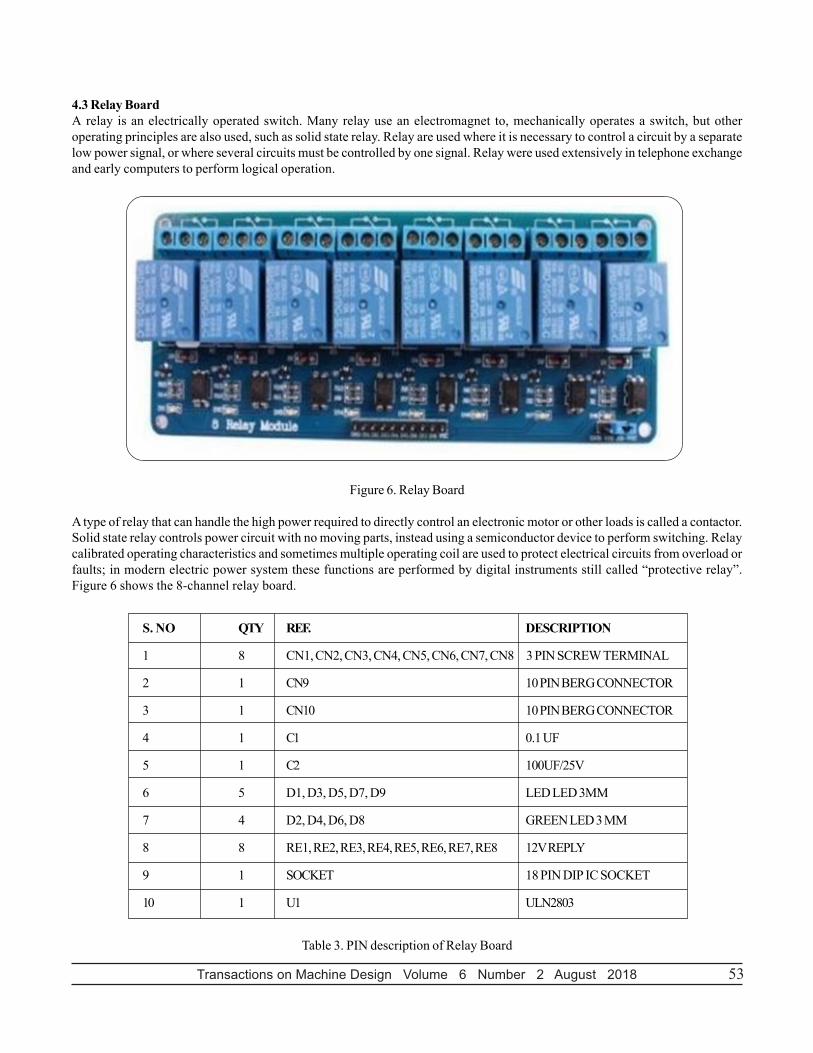
4.3 Relay BoardA relay is an electrically operated switch. Many relay use an electromagnet to, mechanically operates a switch, but otheroperating principles are also used, such as solid state relay. Relay are used where it is necessary to control a circuit by a separatelow power signal, or where several circuits must be controlled by one signal. Relay were used extensively in telephone exchangeand early computers to perform logical operation.
Figure 6. Relay Board
A type of relay that can handle the high power required to directly control an electronic motor or other loads is called a contactor.Solid state relay controls power circuit with no moving parts, instead using a semiconductor device to perform switching. Relaycalibrated operating characteristics and sometimes multiple operating coil are used to protect electrical circuits from overload orfaults; in modern electric power system these functions are performed by digital instruments still called “protective relay”.Figure 6 shows the 8-channel relay board.
S. NO QTY REF. DESCRIPTION
1 8 CN1, CN2, CN3, CN4, CN5, CN6, CN7, CN8 3 PIN SCREW TERMINAL
2 1 CN9 10 PIN BERG CONNECTOR
3 1 CN10 10 PIN BERG CONNECTOR
4 1 C1 0.1 UF
5 1 C2 100UF/25V
6 5 D1, D3, D5, D7, D9 LED LED 3MM
7 4 D2, D4, D6, D8 GREEN LED 3 MM
8 8 RE1, RE2, RE3, RE4, RE5, RE6, RE7, RE8 12V REPLY
9 1 SOCKET 18 PIN DIP IC SOCKET
10 1 U1 ULN2803
Table 3. PIN description of Relay Board

Transactions on Machine Design Volume 6 Number 2 August 2018 54
4.4 Channel Relay BoardDescription8 Channel Relay Board is a simple and convenient way to interface 8 relays for switching application in your project. Inputvoltage level support TTL as well as CMOS. Easy interface with Microcontrollers based projects and analog circuits.
Specifications
1. Input supply 12 VDC @ 336 mA
2. Output eight SPDT relay
3. Relay specification 5 A @ 230 VAC
4. Trigger level 2 ~ 15 VDC
5. Header connector for connecting power and trigger voltage
6. LED on each channel indicates relay status
7. Screw terminal connector for easy relay output and aux power connection
8. Four mounting holes of 3.2 mm each
9. PCB dimensions 152 mm x 60 mm
5. Software
5.1 Arduino IDEA minimal Arduino C/C++ sketch, as seen by the Arduino IDE programmer, consist of only two functions.
• Setup (): This function is called once when a sketch starts after power-up or reset. It is used to initialize variables, input andoutput pin modes, and other libraries needed in the sketch.
• Loop (): After setup () has been called, function loop () is executed repeatedly in the main program. It controls the board untilthe board is powered off or is reset.
Most Arduino boards contain a light-emitting diode (LED) and a load resistor connected between pin 13 and ground, which isa convenient feature for many tests and program functions. A typical program for a beginning Arduino programmer blinks a LEDrepeatedly.
This program uses the functions pin Mode (), digital Write (), and delay (), which are provided by the internal libraries includedin the IDE environment. The program is usually loaded in the Arduino by the manufacturer. Arduino IDE and C language allowthe programming of the low level registers in the atmega328P. Instructions like DDRB=0b00000001 for changing PORTB input/output pins are allowed. Figure 7 shows the basic program of Arduino IDE.
5.2 Web ServerA web server (sometimes called an HTTP server or application server) is a program that serves content using the HTTPprotocol. This content is frequently in the form of HTML documents, images, and other web resources, but can include any typeof file. The content served by the web server can be pre-existing (static content) or generated on the fly (dynamic content).
In order to be considered a web server, an application must implement the HTTP protocol. Applications built on top of webservers (such as blogging software, forums, or wikis) belong in the separate web software category. A user agent, commonly aweb browser or web crawler, initiates communication by making a request for a specific resource using HTTP and the serverresponds with the content of that resource or an error message if unable to do so. The resource is typically a real file on theserver’s secondary storage, but this is not necessarily the case and depends on how the web server is implemented.While theprimary function is to serve content, a full implementation of HTTP also includes ways of receiving content from clients. Thisfeature is used for submitting web forms, including uploading of files.Web servers are not only used for serving the World WideWeb. They can also be found embedded in devices such as printers, routers, webcams and serving only a local network. Theweb server may then be used as a part of a system for monitoring or administering the device in question. This usually means

Transactions on Machine Design Volume 6 Number 2 August 2018 55
Figure 7. Arduino IDE
that no additional software has to be installed on the client computer, since only a web browser is required (which now isincluded with most operating systems).
5.3 Esp8266 FrameworkESP modules are available from a variety of sources, and the firmware contained in the ESP8266 chips on the modules is almostalways outdated and often of questionable origin. The firmware “updates” and tools that are available from these same sourcesare also sometimes suspect. Consequently, it is the aim of this article to document a procedure for downloading the latestavailable firmware directly from Espresso if and installing it on an ESP8266 using the flash tool provided by Espresso. In orderto update the firmware on any ESP8266, it is necessary to have it properly powered and connected to a PC. In addition, a meansof resetting the IC and putting it in the download mode must be provided. The schematic diagram and photograph below showthe recommended setup; note that the wire colors in the schematic correspond to the wire colors.
6. Future Enhancement
Android app will also develop for easily use. In Android app there will be direct buttons for ON or OFF the system or to receivethe OTP. For more security purpose camera module can also be implemented on the system. If any person attempt to enter inhome with more than three time wrong password then at that time camera module will be activate. And camera module willcapture the image of person who trying to attack on system. It can use antivirus so that hacking of the system can be difficult.
7. Problems Faced
In this system Wi-Fi module is a very important part for communication between mobile phone and microcontroller. Wi-Fi module

Transactions on Machine Design Volume 6 Number 2 August 2018 56
requires only 3.3v power whereas the Relay board needs more power. Thus separate power will be given to both the relay andmicrocontroller. Connection between the microcontroller and Wi-Fi module and relay should not be loose if it is loose the systemwill not work properly.
8. Conclusions
In this paper, a novel architecture for low cost and flexible home Automation system using Arduino microcontroller is proposedand implemented. Overall Arduino is easy to understand & its coding is easy. By implementing this type of system we canensure that the energy conservation can be done. By help of this system we can increase the efficiency of the appliances .we canhave the complete control over the home appliances from a long distance. This will Increase the comfortability of human beingand it will reduce the Human efforts.
References
[1] Sharma, Raj., Chirag, Pranjalkatara, Shankar, Vishnu. Proceedings of IEEE TechSym 2014 Satellite Conference VIT University,Paper on Advanced Low-Cost Security system using sensors, Arduino and GSM communication module.
[2] DeepaliJavale, Mohd., Mohsen, Nandewar, Shreerang., MayurShingate. (2013). Home Automation and Security using AndroidADK, (March).
[3] Yavuz, E., Hasan, B., Serkan, I., Duygu, K. (2007). Safe and Secure PIC Based Remote Control Application for IntelligentHome, 7 (5) (May).
[4] Sriskanthan, N., Karand, Tan. (2002). Bluetooth Based Home Automation System. Journal of Microprocessors andMicrosystems, Vol. a. 26. p.281-289.
[5] Kusuma, S. M. (1999). Assistant Professor, Department of telecommunication, MSRIT, Bangalore, India. Home AutomationUsing Internet of Things. (July).
[6] NiharikaShrotriya, Kulkarni, Anjali., PritiGadhave. (1996). SMART HOME USING WI-FI, International Journal of Science,Engineering and Technology Research (IJSETR).
[7] Anu shri, Aware., Vaidya, Sonali., Ashture, Priyanka., Gaiwal, Varsha. (1991). PES’s Modern College of Engineering, Pune-04,International Journal of Engineering Research and General Science, Volume 3, Home Automation using Cloud Network.(February).