home automation application based on arduino … ii. report.pdf · home automation application...
TRANSCRIPT

BACHELOR’S THESIS
Degree in Industrial Electronics and Automatic Engineering
HOME AUTOMATION APPLICATION BASED ON ARDUINO
CONTROLLABLE FROM MOBILE
VOLUME II
Report
Author: Anna Merino Herreros Director: Sebastián Tornil Sin Date: May, 2017

Home automation application based on Arduino controllable from mobile
ii

Anna Merino Herreros
iii
Resum
Aquest projecte es basa en la construcció d’una maqueta que simula una casa domòtica amb
diferents modes de funcionament i que, a més, es pot controlar des de una aplicació mòbil.
Per assolir-ho, s’ha desenvolupat una casa a escala que capta diferents senyals, tant analògiques
com digitals. Per acostar l’aplicació a una casa domòtica real, les variables sotmeses a estudi i
control són la temperatura i la il·luminació interiors, el moviment al voltant de la casa i el nivell
d’aigua de la piscina.
La casa té tres modes de funcionament principals. En mode automàtic realitza la mesura i executa
el control de les variables, és a dir, s’autoregula segons les condicions a les que estigui sotmesa. En
canvi, el mode remot s’assoleix mitjançant la utilització d’una aplicació mòbil que permet a
l’usuari modificar les variables a lliure elecció. Per últim, en mode alarma controla els paràmetres
que vetllen per la seguretat de la casa quan el propietari està absent.
Per captar els senyals el prototip té instal·lats sensors de temperatura, llum, moviment i nivell
d’aigua i per la regulació i control té un ventilador, alguns LED, un avisador acústic i una bomba
d’aigua. El nucli és una placa Arduino Mega que permet el funcionament de l’aplicació i que rep, a
través d’una aplicació mòbil Android, ordres de mode de funcionament i, en cas de estar en mode
remot, per a controlar de forma individual els diferents actuadors. Per la transmissió de dades de
l’aplicació a la placa s’utilitza la comunicació via Bluetooth.

Home automation application based on Arduino controllable from mobile
iv
Resumen
El presente proyecto se basa en la construcción de una maqueta que simula una casa domótica
con diferentes modos de funcionamiento y que, además, se puede controlar mediante una
aplicación móvil.
Para conseguirlo se ha desarrollado una casa a escala que capta diferentes señales, tanto
analógicas como digitales. Para acercar la aplicación a una casa domótica real las variables
sometidas a estudio y control son la temperatura e iluminación interiores, el movimiento
alrededor de la casa y el nivel de agua de la piscina.
La casa tiene tres modos principales de funcionamiento. En modo automático realiza la medida y
ejecuta el control de las variables, es decir, se autorregula según las condiciones a las que esté
sometida. En cambio, el modo remoto se consigue con la utilización de una aplicación móvil que
permite al usuario modificar las variables a libre elección. Por último, en modo alarma controla los
parámetros que velan por la seguridad de la casa cuando el propietario está ausente.
Para captar las señales el prototipo tiene instalados sensores de temperatura, iluminación,
movimiento y nivel de agua y para la regulación y control tiene un ventilador, varios LED, un
avisador acústico y una bomba de agua. El núcleo es una placa Arduino Mega que permite el
funcionamiento de la aplicación y que recibe, mediante una aplicación móvil Android, órdenes de
modo de funcionamiento y, en caso de estar en modo remoto, para controlar de forma individual
los diferentes actuadores. Para la transmisión de datos de la aplicación a la placa se utiliza la
comunicación mediante Bluetooth.

Anna Merino Herreros
v
Abstract
This project is based on the construction of a model simulating a home automation with different
operation modes which can be controlled also by a mobile application.
To achieve this objective, a scale house that captures different signals, both digital and analog, has
been developed. To approach the house to a real home automation application the variables
under study and control are interior temperature and lighting, movement around the house and
water level of the pool.
The house has three main operating modes. In automatic mode, it performs the measurement
and executes the control of the variables, regulating itself according to the conditions to which it
is exposed. In contrast, the remote mode is achieved using the mobile application that allows user
to modify the variables. Finally, in alarm mode it controls the parameters that assure the security
of the house when proprietor is away from home.
To capture the signals, the prototype has temperature, lighting, movement and water level
sensors installed, and for the regulation and control it has a fan, some LED, an acoustic warning
device and a water pump. The core is an Arduino Mega board that allows the application
operation and receives, from an Android mobile application, operating modes commands and, if it
is operating remotely, orders to individually control the different actuators. For the data
transmission from the mobile to the board, is used communication via Bluetooth.
Home automation application based on Arduino controllable from mobile
vi

Anna Merino Herreros
vii
Acknowledgements
At first I would like to thank my tutor for sharing his knowledge and for the support received
during the project development.
Thanks to my family, without you none of this would have been possible. I owe you my degree
and my strength to face every challenge.
I want also to thank my couple, for the patience and interest, for every support word.

Home automation application based on Arduino controllable from mobile
viii
Anna Merino Herreros
ix
Index
RESUM ____________________________________________________________ III
RESUMEN __________________________________________________________ IV
ABSTRACT __________________________________________________________ V
ACKNOWLEDGEMENTS _______________________________________________ VII
1. INTRODUCTION ____________________________________________________ 2
1.1. Origin ........................................................................................................................ 2
1.1.1. History of automation ............................................................................................ 2
1.1.2. Home automation applications .............................................................................. 4
1.1.3. Arduino boards ....................................................................................................... 5
1.1.4. Mobile applications ................................................................................................ 6
1.2. Objectives ................................................................................................................. 7
2. PROTOTYPE REQUIREMENTS _______________________________________ 8
3. ARCHITECTURE AND COMPONENTS _________________________________ 9
3.1. Arduino Mega ........................................................................................................... 9
3.1.1. Choice of board ...................................................................................................... 9
3.1.2. Parts of Arduino Mega board ............................................................................... 11
3.2. Components ...........................................................................................................15
3.2.1. Sensors .................................................................................................................. 15
3.2.2. Actuators .............................................................................................................. 19
3.2.3. Others ................................................................................................................... 22
3.3. Communication ......................................................................................................24
3.3.1. Overview of standard communications ............................................................... 24
3.3.2. Bluetooth communication ................................................................................... 27
3.4. Mobile Application .................................................................................................28
3.4.1. Choice of software ................................................................................................ 28
3.4.2. Functionality of the application ........................................................................... 28
4. ELECTRONIC DESIGN _____________________________________________ 31
4.1. Block diagram .........................................................................................................31
4.2. Component calculation ..........................................................................................32
4.2.1. Temperature circuit .............................................................................................. 32
Home automation application based on Arduino controllable from mobile
x
4.2.2. Light circuit ........................................................................................................... 35
4.2.3. Water level circuit................................................................................................. 37
4.3. Electronic schematic...............................................................................................38
5. PROGRAMMING ________________________________________________ 39
5.1. General overview of the application ......................................................................39
5.2. Arduino programming ............................................................................................42
5.3. Mobile application programming ..........................................................................49
6. BUDGET _______________________________________________________ 56
6.1. Prototype cost ........................................................................................................56
6.2. Mass production cost .............................................................................................58
7. CONCLUSION ___________________________________________________ 60
8. BIBLIOGRAPHY _________________________________________________ 61


Home automation application based on Arduino controllable from mobile
2
1. Introduction
In broad strokes, the main points of this project are automation and control, electronic boards
and mobile applications and particularly home automation, Arduino boards and Android
applications.
This is the result of the connection of two modern technologies, including hardware and software.
Despite the actuality of these components, they all appeared long ago and have been evolving
throughout history.
1.1. Origin
1.1.1. History of automation
This project is based in automation technology and more specifically in home automation
systems.
Automation is the transfer of tasks normally performed by humans to a set of technological
elements.
An automated system consists of two parts:
Operation: Part formed by elements that act directly on the machine and make it perform
desired operations. These elements are called actuators and some examples are engines,
cylinders or photodiodes.
Control: Brain of system, normally constituted by a programmable automaton, able to
communicate with all constituents of the operation part.
The inclusion of control in the automation system, allows to decide on the development of a
process, manipulating certain variables to get these or other variables to act in the desired way.
Although it seems a recent technology and currently is in full development, automation dates
back to ancient times.
Nowadays nobody thinks of divine forces seeing an automatic door, it is something of the day to
day that we have very internalized. It was not the same with people of Alexandria when Herón,
the great genius of mechanical engineering of classical Greece, invented an automatic door
opening system for a temple in Alexandria.

Anna Merino Herreros
3
Figure 1.1.1. Automatic door designed by Herón of Alexandria.
In spite of being antecedents of automation much earlier, like Osiris statue of ancient Egypt,
crankshaft and mechanic watches of the engineer Al-Jazari (1260) or automats designed by
Leonardo Da Vinci (1452-1519), the industrial revolution is considered as the greatest
technological, socioeconomic and cultural change in history.
It is not completely clear what year the industrial revolution began, but it is speculated that it was
in 1775, when James Watt invented the steam engine. Even so, around 50’s, semiconductors
began to be used, fact that turned out to be a breakthrough because before this, only mechanical
and electromagnetic elements were used.
In 1968 Ford and General Motors raised the specifications that had to have a programmable
electronic controller to be useful in the industry, fact that arises from the need of programming to
optimize processes. In addition, the company Bedford Associates developed a prototype of
industrial controller obtaining what is considered as the first PLC (Programmable Logic Controller)
in history, which was named Modular Digital Controller or MODICON, used by a car manufacturer
in the United States.
Figure 1.1.2. MODICON. First PLC of the history.

Home automation application based on Arduino controllable from mobile
4
Later, in the early 70’s, the Intel company developed the first microprocessor, a 4-bit CPU named
i4004, for the Japanese company Busicom to incorporate it into calculators and by the middle of
that decade it was already incorporated into automatons. It contributed to give more flexibility
because of the ease of programming, as the wired memories disappeared.
Figure 1.1.3. i4004. First microprocessor of the history.
Over years the improvements were continuous, automaton was gaining memory, ability to govern
control loops, communications and programming languages became more powerful, obtaining
faster processing speed, more complex control techniques… Until nowadays, having the great
number of existing automatons, increasingly powerful and useful in different fields, even
disengaging from the industry to open new roads, such as home automation applications.
1.1.2. Home automation applications
Houses have evolved throughout history, from caves with fire to warm and illuminate even
torches and candles and finally the arrival of electricity, which has allowed to increase home
comfort. Later, electronics arrived allowing the use of the appliances, being able to perform
programming routines and regulation processes such as hot and cold washing or video recording.
It was from the 1970’s that integrated systems were used commercially and developed into the
domestic aspect of urban houses, this is when home automation manages to integrate the two
necessary systems, electrical and electronic, in pursuit of the integral communication of house
devices.
It was in the United States where the first devices of building automation appeared, based on the
X-10 protocol. This is a communication protocol for the remote control of electrical devices, using
the pre-existing electrical line to transmit control signals within home automation equipment by
radio frequency pulses which represent digital information. History of automation applications
comprises different stages, beginning with the first protocols oriented to remote control and
following with the great protocols of self-regulation, considered the real home automation
revolution.

Anna Merino Herreros
5
In this way, it was obtained that a house was able to perceive different stimuli (temperature, light
level, presence…) and react to them (regulate climate and lighting, activate an alarm…) while
interacting with humans through different options, like mobile or PC.
At this point, is called home automation to a system capable of automate a house or building
including energy management, security, comfort and communication. It can be integrated
through wired or wireless communication networks, although nowadays the predominant trend is
wireless. It could be defined as the integration of technology into the intelligent design of an
enclosure. The main points of this technology are energy saving, comfort, security,
communication and data accessibility.
Figure 1.1.4. Home automation schematic.
Nowadays thanks to the permanent technological evolution the offer is better and have grater
quality, its use is now more intuitive and perfectly manageable by any user. Today’s home
automation contributes to increase the quality of life, makes the distribution of the house more
versatile, changes environmental conditions by creating different predefined scenes and makes
the home more functional by allowing the development of domestic, professional and leisure
under one single roof.
1.1.3. Arduino boards
The core of this project will be an Arduino board.
Arduino boards were originally created in 2005 by Massimo Benzi of IVRAE Institute for the need
to learn of the computer and electronic students. By then the acquisition of microcontroller board
was expensive and did not offer adequate support, instead he obtains as a result an open-
hardware board with a lot of potential and, what is more, at a very economical cost. Years later it
becomes a DIY (Do It Yourself) technology, a great support for students.

Home automation application based on Arduino controllable from mobile
6
Figure 1.1.5. First prototype of Arduino developed at IVRAE institute.
Later other students joined the project, firstly Hernando Barragán, a student of Colombia
University who contributes with David Mellis, other IVRAE Institute schoolmate, to the
development of an environment for the programming of the processor of this board.
Over time were integrated at “Arduino Team” David Curtielles, who helped to weaken the
hardware interface adding the necessary microcontrollers to integrate support and memory to
the programming language in order to manipulate easily the platform, and Tom Igoe who made
the board most powerful adding USB ports to connect to computers.
They began the distribution free of charge within the faculties of electronics, computing and
design of the same institute. Later the publicist Gianluca Martino helped them to get promoted
until Natan Sadle offered to introduce the boards in mass production.
Arduino boards has finally placed in the number one of learning tools for the development of
automaton systems.
1.1.4. Mobile applications
The prototype on which this project is based can be controlled from a customized mobile
application.
A mobile application is a computer application designed to be executed on smartphones, tablets
and other mobile devices which allows the user to perform specific tasks of any kind, like
professional, educational or social. Apps are usually available through distribution platforms
operated by companies that own mobile operating systems such as Android, iOs, Blackberry or
Windows Phone.
Frist mobile applications dates back to the 90’s, it can place in the first videogames, ring-tones,
calendars and agendas implemented in second generation mobile phones. The popular Tetris

Anna Merino Herreros
7
game was the first game installed in 1994 and three years later Nokia launched the most widely
accepted game named Snake. By the year 2000 the technological breakthrough of the WAP
(Wireless Application Protocol) allowed a greater capacity for the downloading of games
distributed by the telephony operators. But the App real boom came in 2008 with the launch of
the Apple Store of Apple corporation, the release of the first Android SDK and the later Android
Market, renamed as Google Play as a new strategic approach of Google.
Currently, due to the applications, all functions are centralized in a small mobile device: calls, mail,
social network, alarm clock, bank account, photography, GPS and a multitude of other utilities.
The trend is on the raise as more and more users want to carry their life in the pocket:
information, communication and personal and professional resources, all accessible at any time.
1.2. Objectives
The main objective of this project is to design and develop a prototype of a home automation controllable from an Android mobile application. Application must be able to perceive and act and to have various types of operation in order to obtain the purpose for which this technology was invented: maximizing user’s comfort offering an easy way to personalize home.
The steps that should be taken to achieve the expected result are the following:
1) Determine the scope of the application and delimit the points that each mode of operation must deal with.
2) Select the components and software.
3) Electronic design.
4) Program the board.
5) Program the mobile application.
6) Build the house model.
7) Place and weld the components in the model.
8) Test and debug the application.

Home automation application based on Arduino controllable from mobile
8
2. Prototype requirements
As mentioned in the previous section, in order to achieve the objectives set, first of all it is
necessary to establish the needs of the project.
In hardware terms the most important part is the local controller, an Arduino board, which will be
the core of the application, the one that will be communicated with the mobile application and
where the sensors and actuators will be connected. The sensors needed to capture desired
environmental variables are temperature, lighting, movement and water level sensors and to
control these variables a fan, some LED, an acoustic warning and a water pump are required.
Finally, to make effective the necessary communication between the board and the mobile will be
needed a Bluetooth device.
As for software, one of the advantages of using an Arduino board as a local controller is that it has
its own development environment or IDE (Integrated Development Environment) that provides
facilities for software development. For the other programming part, will be necessary another
software to program the mobile application.

Anna Merino Herreros
9
3. Architecture and components
3.1. Arduino Mega
Arduino is a development board that integrates a microcontroller and its support circuitry with
digital and analog inputs and outputs. It has an open source computing development platform
based on an environment for programs creation.
3.1.1. Choice of board
Shown below there is a comparison chart with the commonly used boards for this type of
application including their most important characteristics.
Table 3.1. Arduino boards comparison chart.
ARDUINO BOARD
Mic
roco
ntr
olle
r
Inp
ut
volt
age
Op
era
tin
g vo
ltag
e
Ou
tpu
t cu
rre
nt
Clo
ck f
req
ue
ncy
Flas
h m
em
ory
SRA
M
EEP
RO
M
Dig
ital
I/O
PW
M o
utp
uts
An
alo
g in
pu
ts
DUE AT91SAM3X8E 7-12 V 3,3 V 130 mA 84 MHz 512 KB 96 KB
54 12 12
LEONARDO
ATmega32u4 7-12 V 5 V 40 mA 16 MHz 32 KB 2,5 KB 1 KB 20 7 12
MEGA ATmega2560 7-12 V 5 V 20 mA 16 MHz 256 KB 8 KB 4 KB 54 12 16
PRO ATmega328 5-12 V 5 V 40 mA 8 MHz 32 KB 2 KB 1 KB 14 6 6
UNO ATmega328P 7-12 V 5 V 20 mA 16 MHz 32 KB 2 KB 1 KB 14 6 6

Home automation application based on Arduino controllable from mobile
10
Election parameters:
1) Pins:
One of the most important characteristics to keep in mind when choosing an Arduino board is the
number of inputs and outputs. It can be digital or analog, depending on the application it is more
important to pay attention in one type or another, but usually one parameter depends on the
other, if the board has an important number of digital inputs, the analog input number will be
considerable too because it normally has relation with the size of the board.
In this case, both digital and analog pins matter because the project involves digital and analog
components and all of them will be connected to the board, the core of the application and the
responsible of the information collection. Taking into account that the two types of pins are
needed, that the project has 14 components and that the number could increase with the
progress of the project, the best option is to choose a board which contains more pins than are
needed at the beginning of the project so that at the end there is no risk of missing. Then the
orange shaded types are discarded for having a pin number very fair for the scope of the project.
2) Memory:
Flash memory is the program space, where the program is stored. At the beginning of the project,
without knowing what programming will behave in terms of size, and knowing that the
application will have several operation modes and can grow as project progress, the safest way to
avoid having to go back in an advanced stage is to ensure that the memory will be sufficient. For
this reason, the yellow shaded types are discarded for having less KB of flash memory.
SRAM (Static Random Access Memory) is a type of volatile memory where program is stored and
it manipulates variables when executing. The information stored will be delated when the power
is lost since this memory is only for the program execution. If SRAM run out of space, the program
will fail unexpectedly, even if it is compiled and uploaded to board correctly the application will
not run or be run in an unwanted way. This is a very important point to have a fully functional
application, so the blue shaded types are marked for having few KB of this memory.
EEPROM (Electrically Erasable Programmable Read-Only Memory) memory is a RAM memory
programmable and electrically erasable, unlike the EPROM that must be erasable by ultraviolet
rays. Is a non-volatile memory, it means that is capable to retrieve data after power down.
Arduino Due has no EEPROM and although it is not planned to use, is a parameter that should
also be evaluated in case that to keep the values stored after a possible loss of power becomes
necessary.

Anna Merino Herreros
11
3) Clock frequency:
Clock frequency refers at which speed CPU (Central Processing Unit) is running and is an indicator
of the processor’s speed. In this case the slowest is Arduino Pro.
4) Operating voltage:
The only board which has an operating voltage different than 5 V is Arduino Due, this is a major
disadvantage in terms of hardware, as all components planned to be used operate at 5 V.
As a summary and final decision, it is considered that the most suitable Arduino board for this
project is Arduino Mega. On the one hand, it is quite similar to Arduino UNO in terms of
electronic characteristics but contains many more pins, and on the other hand, Arduino Due is the
most powerful board in this range but it presents a problem due to hardware incompatibility with
project components.
3.1.2. Parts of Arduino Mega board
Figure 3.1.1. Arduino Mega board.

Home automation application based on Arduino controllable from mobile
12
1. µC:
This board is based on the ATmega2560 microcontroller.
Table 3.2. ATmega256 configuration summary.
Device Flash memory EEPROM RAM General purpose
I/O pins 16-bit resolution PWM channels
Serial UART ADC
channels
ATmega2560 256 KB 4 KB 8 KB 70 12 4 16
Figure 3.1.2. ATmega2560 pinout.
This microcontroller uses AVR technology, created by Atmel manufacturer, which belongs to RISC
(Reduced Instruction Set Computer) microcontrollers family. In computational architecture, RISC is
a type of CPU design with fixed size instructions presented in a reduced number of formats, in
which only the loading and storage instructions access the data memory and with many general
purpose registers.
The goal of this architecture is to enable segmentation and parallelism in the instruction execution
and reduce access to memory.
Anna Merino Herreros
13
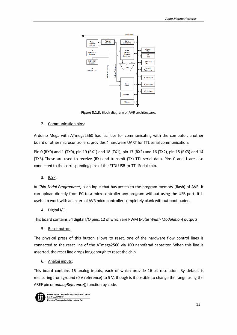
Figure 3.1.3. Block diagram of AVR architecture.
2. Communication pins:
Arduino Mega with ATmega2560 has facilities for communicating with the computer, another
board or other microcontrollers, provides 4 hardware UART for TTL serial communication:
Pin 0 (RX0) and 1 (TX0), pin 19 (RX1) and 18 (TX1), pin 17 (RX2) and 16 (TX2), pin 15 (RX3) and 14
(TX3). These are used to receive (RX) and transmit (TX) TTL serial data. Pins 0 and 1 are also
connected to the corresponding pins of the FTDI USB-to-TTL Serial chip.
3. ICSP:
In Chip Serial Programmer, is an input that has access to the program memory (flash) of AVR. It
can upload directly from PC to a microcontroller any program without using the USB port. It is
useful to work with an external AVR microcontroller completely blank without bootloader.
4. Digital I/O:
This board contains 54 digital I/O pins, 12 of which are PWM (Pulse Width Modulation) outputs.
5. Reset button:
The physical press of this button allows to reset, one of the hardware flow control lines is
connected to the reset line of the ATmega2560 via 100 nanofarad capacitor. When this line is
asserted, the reset line drops long enough to reset the chip.
6. Analog inputs:
This board contains 16 analog inputs, each of which provide 16-bit resolution. By default is
measuring from ground (0 V reference) to 5 V, though is it possible to change the range using the
AREF pin or analogReference() function by code.

Home automation application based on Arduino controllable from mobile
14
7. Power pins:
Vin when an external power source is used, voltage can be supplied using this pin.
GND ground pin, 0 V reference.
5 V the regulated power supply used to power the microcontroller and other components on
the board. This can come either from Vin via an on-board regulator or be supplied by USB or
another regulated 5V supply.
3 V a 3 V supply generated by on-board chip, with a maximum current of 50 mA.
IOREF the value connected to his pin will work as a voltage reference.
8. Regulator 3,3 V:
This electronic component delivers 3,3 V and if it receives more voltage is absorbed and dissipated
to avoid component damaging.
9. External power supply:
It can be powered by USB or with an external supply of 6 to 20 V.
10. Regulator 5 V:
It has de same function as 3,3 V one but operating with 5 V, in case of being supplied by this
voltage.
11. Crystal oscillator:
Arduino Mega’s clock oscillator has a 16 MHz clock speed.
12. Fuse USB:
The Arduino Mega has a resettable polyfuse to protect computer's USB port. If more than 500 mA
is applied, the fuse will automatically break the connection until the short or overload is removed.
13. USB port:
USB port can be used to power the board and to load the code.
14. µC:
ATMEGA16U2 microcontroller allows the ability to upload binary code generated after compiling
the program developed by the user.
15. PWM:
Type of digital outputs used to modify the cycle of a periodical signal.

Anna Merino Herreros
15
3.2. Components
3.2.1. Sensors
LM35 temperature sensor
Integrated circuit temperature sensor with linear analog output proportional to the Centigrade
temperature. It has low input impedance and an accurate calibration. The most common
encapsulation is TO-92, used in low-power transistors.
Figure 3.2.1. LM35 temperature sensor.
Main characteristics:
Supply voltage: 4 – 30 V
Current drain: less than 60 μA
Linear scale factor: 10 mV/ºC
Range: -55 – 150 ºC
Accuracy: ±1/4
Figure 3.2.2. LM35 sensor pinout.
Home automation application based on Arduino controllable from mobile
16
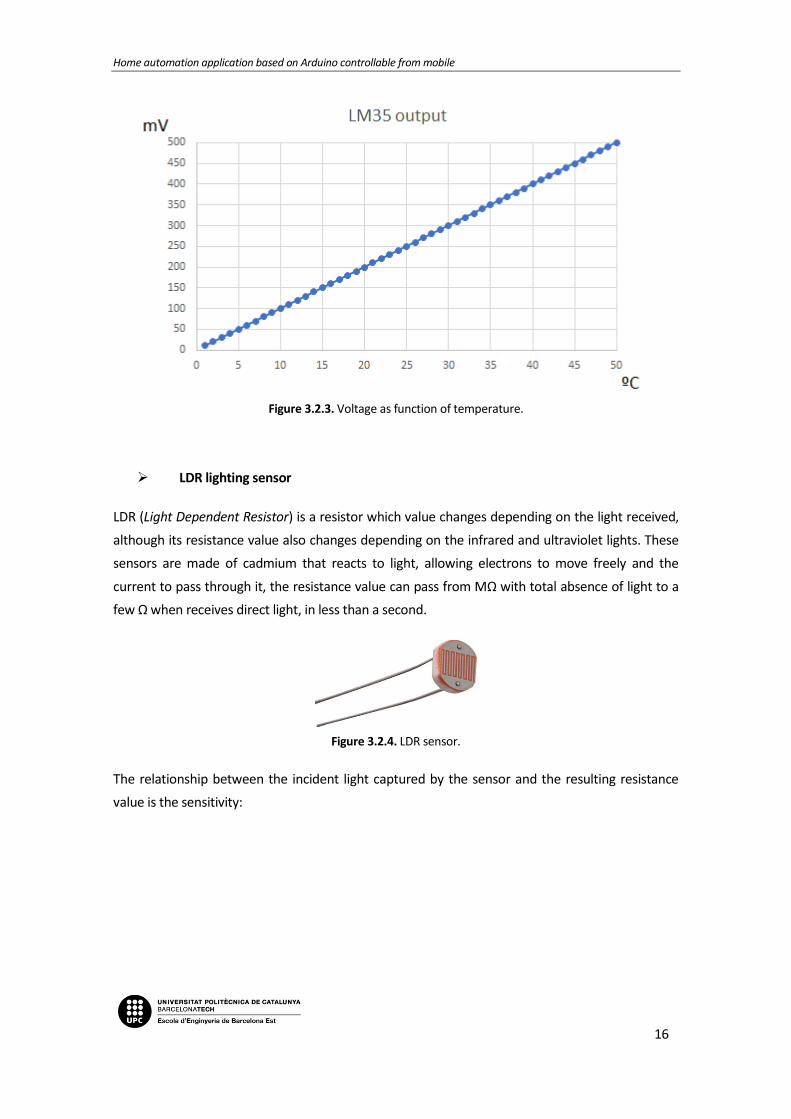
Figure 3.2.3. Voltage as function of temperature.
LDR lighting sensor
LDR (Light Dependent Resistor) is a resistor which value changes depending on the light received,
although its resistance value also changes depending on the infrared and ultraviolet lights. These
sensors are made of cadmium that reacts to light, allowing electrons to move freely and the
current to pass through it, the resistance value can pass from MΩ with total absence of light to a
few Ω when receives direct light, in less than a second.
Figure 3.2.4. LDR sensor.
The relationship between the incident light captured by the sensor and the resulting resistance
value is the sensitivity:

Anna Merino Herreros
17
Figure 3.2.5. Resistance as function of illumination.
PIR motion sensor
Motion PIR (Passive InfraRed) sensor reacts only to certain energy sources like head released by
the human or animal bodies. Its operation is based on perceiving the difference of infrared
radiation in the surrounding area.
Figure 3.2.6. PIR movement sensor.
It is constituted by a crystalline material which generates a surface electric charge when it is
exposed to head in form of infrared radiation, when the quantity of radiation perceived changes,
it contains a Fresnel filter which changes output in order to indicate movement in surroundings.
It also contains an amplifier, which behaves as an active filter rejecting the high frequency noise,
followed by a comparator which responds to a positive and negative transitions from output
sensor signal.

Home automation application based on Arduino controllable from mobile
18
Figure 3.2.7. PIR sensor configuration.
This sensor includes detection elements configured to cancel signals caused by vibration,
temperature changes or sunlight. It has two variable calibration resistors: one is for establish the
time that its output is kept, the other is to vary detection distance between 3 and 7 meters.
Main characteristics:
Supply voltage: 4,5 – 20 V
Controller: PIR BISS0001
Detection range: 3-7 m
Fresnel lens: 19 zones, angle < 100º
Configurable output timer by trimmer (Tx)
Configurable retrigger by jumper
DIY T1592 water level sensor
The principle of this sensor is to measure the size of the water droplets through the line with a
serie of conductor wires exposed in parallel. This sensor give as an output 2,3 V when perceive the
maximum quantity of water and 0 V with totally absence of water.
Figure 3.2.8. DIY T1592 water level sensor.

Anna Merino Herreros
19
Main characteristics:
Supply voltage: 3,3 - 5 V
Output voltage: 0 - 2,3 V
Working current: < 20 mA
Detection area: 40 mm x 16 mm
3.2.2. Actuators
Fan
Cooling fan which transmits energy to generate the necessary pressure with which a continuous
flow of air is maintained. It is axial type, which means that the air inlet and outlet follow a path
according to coaxial cylindrical surfaces. In this case, its brushless DC motor will be energized
when the NPN transistor to which is connected saturates.
Figure 3.2.9. 5 V fan.
Main characteristics:
Supply voltage: 3,5 - 6 V
Current rating: 0,215 A
Operating temperature: -10 – 10 ºC
Fan type: axial
Propulsion: brushless DC motor
LED
Light Emitting Diode. Unlike diodes, LED does not use silicon crystals as a semiconductor element. It uses a combination of other semiconductor materials that emit photons of different colours when a current pass through it. It is formed by two polarities, one positive or anode and the other negative or cathode. At the junction between both a potential barrier is formed to prevent the exchange of electrons between the two regions.

Home automation application based on Arduino controllable from mobile
20
When voltage is applied and LED is directly polarized, the electrons from source flows through it
and whenever an excess electron negatively charged overcomes the potential barrier resistance,
crosses it and it combined with a positive gap in excess. The energy acquired by the electron to
cross the barrier, becomes electromagnetic energy that releases as a light photon.
Figure 3.2.10. LED.
Buzzer
Is a piezoelectric transducer, a device that converts electrical signals into sound. Piezoelectric
materials have the possibility of varying its volume when being crossed by electrical currents.
Figure 3.2.11. LED.
A buzzer takes advantage of this phenomenon to vibrate a membrane by traversing the
piezoelectric material with an electric signal.

Anna Merino Herreros
21
Figure 3.2.12. Buzzer structure.
Water pump
The general features of magnetic water pumps include a rotatory impeller located in a closed case
driven by a rotating magnetic field produced by individual magnets. Rotation of the impeller
produces a force that drives the liquid through and out of the pump case.
Figure 3.2.13. Water pump.
Main characteristics:
Supply voltage: 2,5 - 6 V
Flow: 80 – 120 l/h
Outside diameter of water outlet: 7,5 mm
Conduction mode: brushless continuous current, magnetic conduction

Home automation application based on Arduino controllable from mobile
22
3.2.3. Others
PCB
Printed Circuit Board. Is a non-conductive base with a bus of conductive material. It is used on the
one hand to connect electrically components using the conductive tracks, and on the other hand
to hold the components using the base.
Figure 3.2.14. PCB.
Wires
Element that allows closing an electrical circuit. It has to be combined with soldering.
Figure 3.2.15. Wires.

Anna Merino Herreros
23
Resistors
Resistors restrict the current flow in a circuit.
Figure 3.2.16. Resistances.
2N2222 transistor
Low power bipolar transistor NPN. It is used for applications both switching and amplification. It can amplify small currents to a small or medium voltage, therefore it can only work at low power and medium frequencies.
But in this case, it is used for the switching function, in which it needs to have a certain current
base so that the transistor saturates and turn the fan on to cool the sensors that have reached the
threshold value. To turn the fan off, current must be null.
Figure 3.2.17. 2N2222 transistor.
Home automation application based on Arduino controllable from mobile
24
3.3. Communication
To establish the communication needed between Arduino and mobile application are studied the
most commonly used communication technologies.
3.3.1. Overview of standard communications
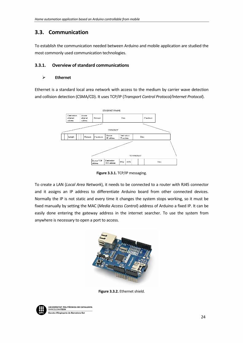
Ethernet
Ethernet is a standard local area network with access to the medium by carrier wave detection
and collision detection (CSMA/CD). It uses TCP/IP (Transport Control Protocol/Internet Protocol).
Figure 3.3.1. TCP/IP messaging.
To create a LAN (Local Area Network), it needs to be connected to a router with RJ45 connector
and it assigns an IP address to differentiate Arduino board from other connected devices.
Normally the IP is not static and every time it changes the system stops working, so it must be
fixed manually by setting the MAC (Media Access Control) address of Arduino a fixed IP. It can be
easily done entering the gateway address in the internet searcher. To use the system from
anywhere is necessary to open a port to access.
Figure 3.3.2. Ethernet shield.

Anna Merino Herreros
25
Wi-Fi
Wi-Fi is a WLAN (Wireless Local Area Network), the alternative to the wired local network that
uses too TCP/IP protocol. The name is a registered brand, acronym of Wireless Fidelity, and there
are a multitude of devices enabled to use this type of communication.
Figure 3.3.3. Wi-Fi shield.
ZigBee
ZigBee is the specification of a set of high-level wireless communication protocols for use with
low-power digital broadcasting based on the standard of WPAN (Wireless Personal Area
Network). Its goal is applications that require secure communications with low data rate and
maximize the life of batteries.
Xbee is the brand name of RF (Radio Frequency) communication module from Digi International
that transmits and receives data over the air using radio signals. There are many types, some are
based on the ZigBee standard and others are proprietary or standard modifications.
Figure 3.3.4. Xbee module.

Home automation application based on Arduino controllable from mobile
26
Bluetooth
Bluetooth is an industrial specification for WPAN (Wireless Personal Area Network), that enables
the transmission of data and voice between different devices through a radiofrequency link in the
2.4 GHz ISM band. The main objectives to be achieved with this standard are facilitate
communication between mobile devices, remove cables and connectors between them and offer
the possibility to create small wireless networks facilitating the synchronization of data between
personal equipment. All Bluetooth devices have a unique address of 48 bits and a device name
that allows the identification of each other.
Devices that incorporate this protocol can communicate with one another when within its reach.
The communications are by radiofrequency so that the devices do not have to be aligned and can
even be in separate rooms if the transmission power is sufficient. These devices are classified as
Class 1, Class 2 and Class 3 depending on the transmission power.
Table 3.2. Bluetooth classification by class.
Class Maximum Power
(mW) Maximum Power
(dBm) Range
Class 1 100 mW 20 dBm 100 m
Class 2 2.5 mW 4 dBm 10 m
Class 3 1 mW 0 dBm 1 m
There are two main Bluetooth modules compatibles with Arduino and other microcontrollers: HC-
05 and HC-06. These are both of Class 2 and ease to use thanks to its SPP (Serial Port Protocol).
Bluetooth module HC-06 is only capable to work as Slave, it means that it can be connected only
to a Master and it has a reduced set of instructions which it can attend. On the other hand,
Bluetooth module HC-05 is capable both to work as Slave and as Master, it can be connected to a
more than one Slave and receive and request information from all of them, arbitrating the
transfer of information (maximum 7 slaves) and can attend to a greater number of configuration
commands.

Anna Merino Herreros
27
3.3.2. Bluetooth communication
After a global communication overview, it is decided to use Bluetooth for the communication
between Arduino and mobile application, more specifically HC-05 module.
This module is finally chosen to meet all application requirements. It is a wireless technology, the
sender and the receiver are not physically connected, but trough electromagnetic waves. It has a
range of 10 meters, enough to be able to control the variables using mobile phone, since this type
of control make sense when the user is inside the house. Finally, the only additional requirement
to make the communication between both devices is that the mobile phone has Bluetooth
connectivity, which nowadays is a standard characteristic of mobiles.
Main characteristics:
Configurable as Slave and as Master.
Radio chip: CSR BC417143.
Frequency: 2.4 GHz ISM band.
Modulation: GFSK (Gaussian Frequency Shift Keying).
Built-in PCB antenna.
Emission Power: ≤ 4 dBm (Class 2).
Range: 10 m.
Speed: Asynchronous: 2.1 Mbps/160 kbps; Synchronous: 1 Mbps/1 Mbps.
Security: Authentication and encryption.
Profiles: Serial port Bluetooth.
Current consumption: 50 mA.
Supply voltage: 3.6 V – 6 V.
Operation temperature: -20 ºC – 75 ºC.
Figure 3.3.5. Bluetooth HC-05.
Home automation application based on Arduino controllable from mobile
28
3.4. Mobile Application
3.4.1. Choice of software
Nowadays thanks to the boom of mobile applications there are infinite possibilities to build one.
One of them is to use a software in which is not needed to know anything of code, fact that
facilites access to non-experienced users, but the problem of this option is that it greatly restricts
the field of action in terms of functionality and default templates are often used, which also limits
user’s challenge of design own and unique mobile application. For these reasons, these types of
software are discarded to be used during this project.
After this first selection, there are many software valid for the purpose of this project. The
application was started to develop using Android Studio, but the lack of experience programming
with Java turned the activity more difficult as the development of the application progressed.
Then it was decided that the best way to continue with the design and development was to use
Google App Inventor software, an integrated development environment to create mobile
applications for Android operating system. The application’s block editor uses the open blocks
Java library to create a more intuitive language. The compiler that translates visual block language
to Android uses Kawa as a programming language.
Its resulting applications allows to cover a great number of basic needs in a mobile device,
including all the requirements for the project application, but may be limited for other
applications with more complexity.
3.4.2. Functionality of the application
Mobile application is programmed to connect to a Bluetooth device to be able to send orders to
Arduino board.
Once it is connected, user has to select between three main modes: Automatic, Remote and
Alarm.
Automatic mode
Each time the user selects this mode, the prototype has to be able to get temperature, lighting and water level values from different sensors and act according to the information collected, determined by Arduino code uploaded in its microprocessor.
The following control loops must be in operation when automatic mode is chosen in order to automate home functions:
A fan has to be activated when the temperature value is greater than a pre-established threshold. When sensor senses that temperature is higher than the marked value, fan will be activated until temperature stabilizes below that value.

Anna Merino Herreros
29
Figure 3.4.1. Graphic of temperature automatic control.
A group of LED has to be turned on gradually when the light sensor receive less light, with
the purpose of compensate the lack of natural light with artificial light. In conditions of maximum value of natural light all LED will be off, as the natural light decreases it will be compensated with artificial light to maintain the same condition. In this situation, the darker it will be, the more LED will be lighted up: with less than 20 % of natural light all LED will be on, between 20 % and 40 % three LED will be on, between 40 % and 60 % two LED will be on, between 60 % and 80 % one LED will be on and with more than 80 % all LED will be off.
Figure 3.4.2. Graphic of lighting automatic control.
A water pump has to be activated when the water level is greater than a pre-established threshold.

Home automation application based on Arduino controllable from mobile
30
Remote mode
In addition, all actuators must be controlled by a mobile application programmed specifically for this purpose and the user has to be able to let the house self-regulate its own variables or control it manually from the App, regardless of the values perceived by the sensors. Mobile application has a section in which user can control manually the number of LED that are going to be turned on, then user can turn on or off each LED separately or turn on or off all LED on at once.
It has another section in which user can control manually the fan, regardless of the ambient temperature.
Finally, the user will also be able to control pool level activating or deactivating water pump to
empty the pool to desired level.
Alarm mode
When alarm mode is selected, application works with active alarm and level pool loops, to avoid water overflow in case of rain and entry of thieves into the property. In this way, if water level sensor is activated, water pump is activated until sensor stops sensing and if movement sensor detects movement around the house, an alarm is activated together with a flashing red LED. In this case, it can be seen by the user in the application only if alarm mode is activated.

Anna Merino Herreros
31
4. Electronic design
4.1. Block diagram
Below is shown the diagram block of the entire application:
Figure 4.1.1. Block diagram of the application.
The core of the application, where all the information is centralized, is the microcontroller
ATmega2560 included in the Arduino Mega board. The code is continuously executed in it and it
collects all function modes, receiving orders of the mobile application, information of the
environment through sensors and governing all the actuators connected after processing all the
data acquired.

Home automation application based on Arduino controllable from mobile
32
4.2. Component calculation
4.2.1. Temperature circuit
Temperature sensor:
As is specified in ATmega2560 microcontroller datasheet of Atmel manufacturer, it incorporates a
10-bit ADC.
If is taken a temperature range of 0 to 100 ºC and LM35 temperature sensor is calibrated so that
each degree Celsius is equal to 10 mV as output:
(Eq. 4.1)
At the maximum temperature the output will be 1 V and the maximum value of ADC is 5 V, so it
means that a percentage of range is lost:
(Eq. 4.2)
It is possible to switch internal voltage reference of microcontroller to 1,1 V by code and in this
case the resolution will be more accurate:
(Eq. 4.3)
It can be reach too by adding a voltage divider or an amplifier:
Figure 4.2.1. Amplifier.

Anna Merino Herreros
33
(Eq. 4.4)
(Eq. 4.5)
(Eq. 4.6)
(Eq. 4.7)
(Eq. 4.8)
(Eq. 4.9)
In this way, in conditions of 100 ºC (maximum range value) LM35 sensor will give 5 V as output
signal.
The first solution to increase resolution is dangerous for the reliability of the other analog sensors
results, which must be referenced to 5 V. The code is not so fast as to be able to change for sure
voltage reference on each signal reading and false values can be obtained for both sensors
referenced to 5 V and 1,1 V.
The second solution is more safety for the good function of the system and it will be chosen in
case of necessary, but also has disadvantages. It increases the difficulty of the circuit because it
has to be powered with symmetrical voltage different than 5 V increasing the price too.

Home automation application based on Arduino controllable from mobile
34
The purpose of the temperature control of this project is not to have a great temperature
resolution, it is sufficient to visualize the change of whole degrees (without need of decimals) so
that when the threshold is reached (typically at 25 ºC) being in automatic mode, turn on the fan.
In the case of remote mode is also not necessary, as the user decide by its own thermal sensation
if the fan in turned on or not. So, finally the temperature changes that can capture this project will
be approximately 0,5 ºC, having an output of 0 V at 0 ºC and 1 V at 100 ºC.
Fan:
According to fan datasheet of Sunon manufacturer, its power is 0.44 W. With this information and knowing that it is powered by 5 V:
(Eq. 4.10)
(Eq. 4.11)
(Eq. 4.12)
When the pin where fan is connected receives de signal from code, it will be activated.
The fan speed is not controlled, is an all-or-nothing control, so that when fan is activated it works
always at same speed.

Anna Merino Herreros
35
4.2.2. Light circuit
Light sensor:
By a pair of serial resistors, it is possible to distribute the voltage supplied by the source between
its terminals. Using a LDR sensor it obtains a variable voltage according to the amount of light
sensed, as it is shown below:
Figure 4.2.2. Voltage divider of LDR sensor.
The more light the LDR sensor receives, the less opposite resistance will have and, as a result,
more current will reach the analog pin of the board. Vout changes according to the following
equation:
(Eq. 4.13)
As LDR sensor resistance decreases, Vout is greater, having the maximum value when LDR resistance is null (it is fully lighted) and the minimum value when LDR resistance has it maximum value (it is fully dark). If R is fixed to a 1 kΩ:
Situation 1: LDR fully lighted LDR resistance value close to 0 Ω:
(Eq. 4.14)

Home automation application based on Arduino controllable from mobile
36
Situation 2: LDR fully dark LDR resistance value very high MΩ:
Figure 4.2.3. Voltage as function of resistance.
The microcontroller has a 10-bit ADC, so as the values of the pin where the LDR sensor is
connected will be between 0 and 1024. So, with an output of 5 V ADC value will be 1024 and with
an output of 0 V ADC value will be 0.
If 4 LED are used to compensate the lack of natural light with artificial one, the strategy will be the
following.
Table 4.1. Lighting loop functionality according to ADC value.
ADC value Number of LED lighted
0 – 205 4 LED ON
206 – 411 3 LED ON
412 – 616 2 LED ON
617 – 821 1 LED ON
822 – 1023 0 LED ON

Anna Merino Herreros
37
LED:
A normal LED requires a current of 15 mA approximately. Bearing in mind that the voltage loss
across its terminals is 2 V and that it is powered by a voltage of 5 V, 3 V must fall in the resistor:
(Eq. 4.15)
4.2.3. Water level circuit
Water level sensor:
The water level sensor does not need an additional electronic circuit, it is directly connected to an
analog input of the board.
When it senses the maximum quantity of water that it can perceive, its output is 2,3 V and when it
does not senses a drop of water its output is 0 V. So, having a 10-bit ADC, with the maximum
percentage of water sensed the value will be 1024 and 0 with the lowest.
Water pump:
This component does not need an additional electronic circuit neither, it is connected directly to a
digital pin of the board. When the water sensing conditions defined by code are reached, the
water pump is activated until the water level sensed decrease its value below the activation
threshold.

Home automation application based on Arduino controllable from mobile
38
4.3. Electronic schematic
Anna Merino Herreros
39
5. Programming
5.1. General overview of the application
To get the expected functionality of the project, the application has been programmed by dividing
it into two platforms. Arduino board code is the one that collects all the information and controls
actuators. The other is the code of the mobile application, that defines the operation mode all
time and, in case of being in remote mode, which orders the operation of the actuators, but
always acting through the microcontroller of the board.
Below is shown the block diagram of the entire application.
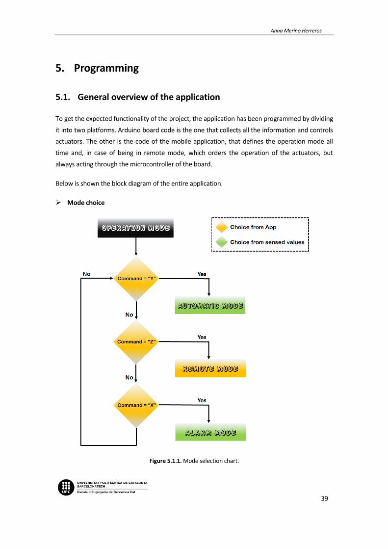
Mode choice
Figure 5.1.1. Mode selection chart.

Home automation application based on Arduino controllable from mobile
40
Automatic mode
Figure 5.1.2. Automatic mode chart.

Anna Merino Herreros
41
Remote mode
Figure 5.1.3. Remote mode chart.

Home automation application based on Arduino controllable from mobile
42
Alarm mode
Figure 5.1.4. Alarm mode chart.
5.2. Arduino programming
As a global overview of Arduino programming, it is divided, as established in the IDE code
development, in two main parts: setup and loop functions. The first is the function that is
executed only the first time that application runs, instead the second one is executed as a loop,
continuously.
For this application additional functions are included to segment and make the program more
efficient. There is a function for each mode of function that includes the necessary control loops.
At the beginning of the Arduino code all the components are delimited: type, the pin to which is
associated and the operation mode. In addition, it is also declared the global variables and the
libraries which will be used in the whole code.

Anna Merino Herreros
43

Home automation application based on Arduino controllable from mobile
44

Anna Merino Herreros
45
Then, application will wait until the order arrives from the mobile application indicating which
mode is going to be executed. This is included in the loop function, the part of the code that is
continuously executed to change the mode in real time at the user’s choice.
Letters are used to send the command that user select to Arduino board.

Home automation application based on Arduino controllable from mobile
46
If Arduino receives a “Y”, it will be use an internal variable called “mode”, the value of which will
be “A” and then the code will execute the automatic mode function. If this mode is in execution
the house will self-regulate following the parameters fixed by Arduino code. Depending on the
natural light perceived a determined quantity of LED will be turned on, depending on the ambient
temperature the fan will be on or off and depending on the water level of the pool the water
pump will be on or off.
Anna Merino Herreros
47
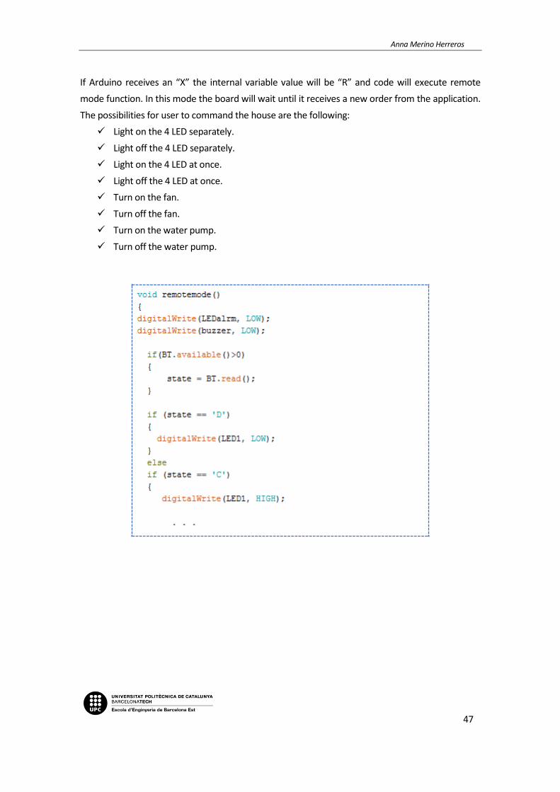
If Arduino receives an “X” the internal variable value will be “R” and code will execute remote
mode function. In this mode the board will wait until it receives a new order from the application.
The possibilities for user to command the house are the following:
Light on the 4 LED separately.
Light off the 4 LED separately.
Light on the 4 LED at once.
Light off the 4 LED at once.
Turn on the fan.
Turn off the fan.
Turn on the water pump.
Turn off the water pump.

Home automation application based on Arduino controllable from mobile
48
Finally, if it receives an “Z” the internal value will be “D” and code will execute alarm mode
function. In this mode the buzzer will be activated together with a blinking red LED when
movement sensor perceives movement around the house and the water pump will be activated
when there is a risk of water overflow in the pool. This is a mode designed expressly for when the
user is absent and want to keep the house under control: without thefts or water overflows that
may bring undesired consequences.

Anna Merino Herreros
49
5.3. Mobile application programming
As already explained in previous sections, the mobile application has the power to choose
between the three modes of operation and data is sent to the board using Bluetooth.
Figure 5.3.1. Mode selection screenshot.
In case of choosing remote mode, user can control all variables from mobile:
Pressing “ON” or “OFF” buttons of each section can light LED 1,2,3 and 4 separately. Pressing “All
ON” or “All OFF” buttons can light all LED at once.
User can see if any LED is on or off in the interface of the application using two visual methods:
will be shown an image of a light bulb on or off and the state written where the image and the
label corresponding to each of them is located. The same will happen in the section of all LED
together.

Home automation application based on Arduino controllable from mobile
50
Figure 5.3.2. Remote mode screenshot - lighting.
For temperature control, user can press “Activate” button to turn on the fan and “Deactivate” to
turn it off.
The fan image will be green in case the fan is activated and brown otherwise. The label placed
near the image will show written the state.
Figure 5.3.3. Remote mode screenshot – temperature.
Anna Merino Herreros
51
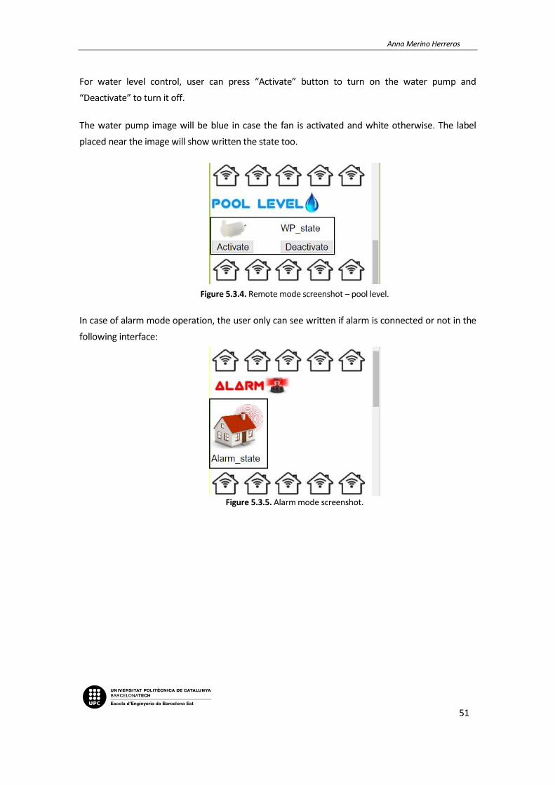
For water level control, user can press “Activate” button to turn on the water pump and
“Deactivate” to turn it off.
The water pump image will be blue in case the fan is activated and white otherwise. The label
placed near the image will show written the state too.
Figure 5.3.4. Remote mode screenshot – pool level.
In case of alarm mode operation, the user only can see written if alarm is connected or not in the
following interface:
Figure 5.3.5. Alarm mode screenshot.
Home automation application based on Arduino controllable from mobile
52
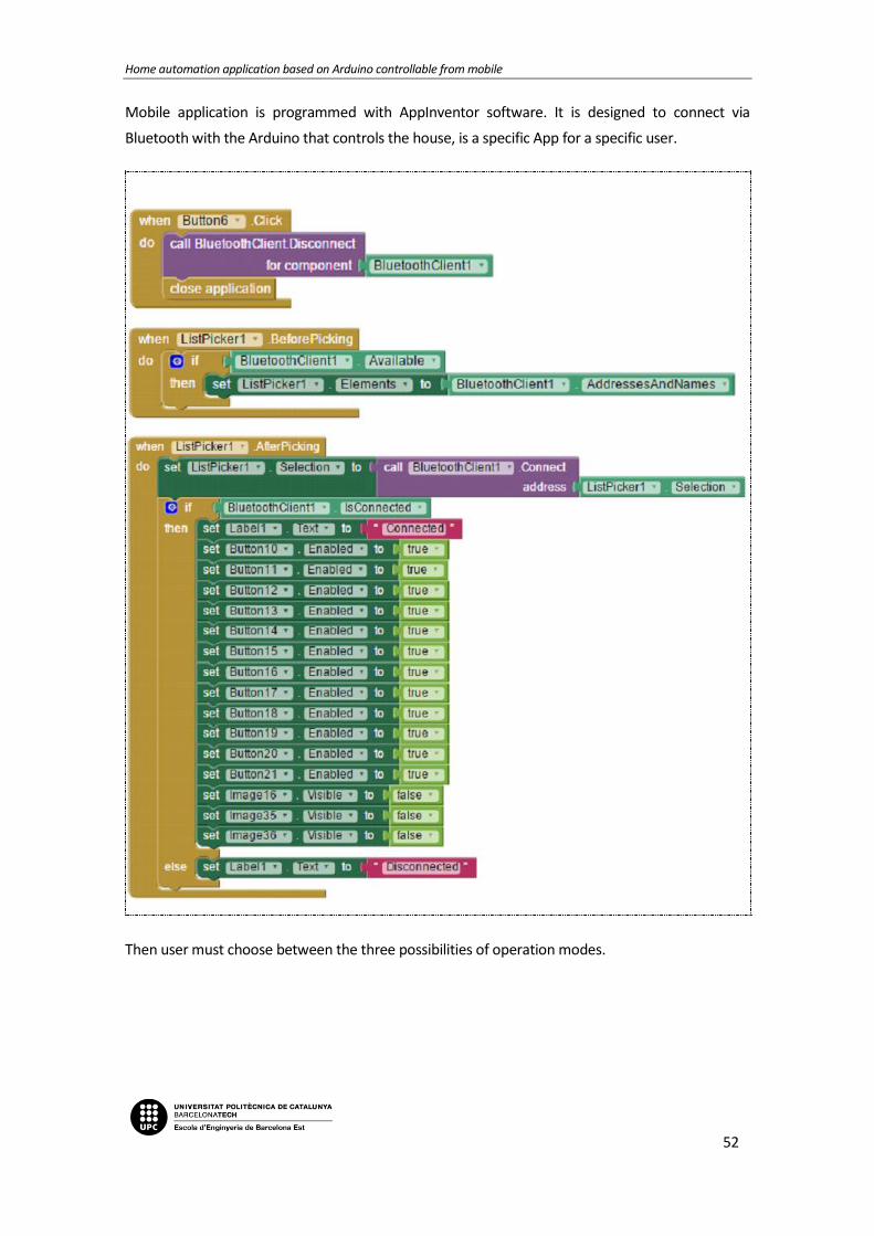
Mobile application is programmed with AppInventor software. It is designed to connect via
Bluetooth with the Arduino that controls the house, is a specific App for a specific user.
Then user must choose between the three possibilities of operation modes.

Anna Merino Herreros
53

Home automation application based on Arduino controllable from mobile
54
Once operation mode is selected, if the one chosen is remote, user will be able to control devices
as desired using the application buttons.
The can change operation mode whenever wanted.

Anna Merino Herreros
55
The application programmed for this purpose uploaded to the mobile can be seen in the following
image:
Figure 5.3.6. Mobile application visualization.

Home automation application based on Arduino controllable from mobile
56
6. Budget
This chapter presents the first cost of the project, which is the cost of the prototype, and the cost
of the application in mass production for sale to the public.
6.1. Prototype cost
The following table shows the cost of the components, both electronic and mechanical, necessary
to successfully develop this application.
Table 6.1. Electronic and mechanical costs.

Anna Merino Herreros
57
The cost in working hours to obtain a functional application is shown in the following table.
Table 6.2. Labour costs.
Adding the costs of the previous tables, it can be obtained the cost of the entire application.
Table 6.3. Total costs.

Home automation application based on Arduino controllable from mobile
58
6.2. Mass production cost
This project could be commercialized as a learning tool to automatic and electronics students.
In this section the cost per model in mass production is calculated.
To obtain the resultant cost, the following parameters must be taken in account:
Buying the components in big batches, can be obtained a considerable discount. In this case,
for the components used, on average it can be discounted 20%.
In order to test the success that can have this model, a considerable number of products
should be produced. So, it is decided to produce 500 units.
To amortize the expenses and obtain benefit, each product will have a charge. In this case the
profit will be 15%.
With above data, and removing the cost of mobile phone, because it is not going to be included in
the pack, protoboard, because it is to perform tests and welding, the cost for components is as
follows.
Table 6.4. Component costs in mass production.

Anna Merino Herreros
59
In mass production the labour cost will be lower for sure and the tasks that only have to be done
once to get the resulting model can be skipped in these calculations.
The tasks that must be executed in this case with its associated cost are the following.
Table 6.5. Labour costs in mass production.
To finish, adding the VAT and profit costs, the final cost per product, the RRP (Recommended
Retail Price) is shown below.
Table 6.6. Recommended Retail Price of home automation model.

Home automation application based on Arduino controllable from mobile
60
7. Conclusion
As it can be seen in the report´s development, all the objectives exposed in point 1.3 have been
accomplished. It has not been an easy project and it required many hours of research to match
expectations.
This thesis is based on what has been learned during the degree, expanding the knowledge in
different areas to obtain a final project where three main electronic parts meet; electronic design
(hardware), programming (software) and communication between devices.
The fact of having chosen home automation as a subject to work on has been fulfilling because it
is an issue which is currently in full expansion and has a promising future. This technology is in
constant expansion and its scope is growing to cover more important areas like security,
accessibility and user´s comfort.
In addition, there is another technology that has been developed, which is currently highly used
and that is mobile applications. Even though there are many platforms that allow users to create
an application, the handicap has been creating an application capable to communicate with other
devices and also making it exclusive to remotely control them. Personally, it has been the very
first time that I created a mobile application and the hardest thing to complete the project was to
make it work as desired. It has also been the most satisfying part.
As a summary, I have dealt with important parts of the degree I studied, using the knowledge
acquired and increasing it, obtaining the know-how to get myself out in the professional market.

Anna Merino Herreros
61
8. Bibliography
[1] Antiquitas (June, 2010). Grecia III: Herón de Alejandría [Message from a Blog]. Available in:
http://historiautomatas.blogspot.com.es/2010/06/grecia-iii-heron-de-alejandria.html
[2] Aplicación móvil. Wikipedia. https://es.wikipedia.org/wiki/Aplicaci%C3%B3n_m%C3%B3vil
[3] Arduino Arduino MEGA 2560 & Genuino MEGA 2560, [in line]. Available in:
https://www.arduino.cc/en/Main/arduinoBoardMega2560Leonardo
[4] Arduino Due, [in line]. Available in: https://www.arduino.cc/en/Main/arduinoBoardDue
[5] Arduino Leonardo [in line]. Available in:
https://www.arduino.cc/en/main/arduinoBoardLeonardo
[6] Arduino MEGA 2560 & Genuino MEGA 2560 [in line]. Available in:
https://www.arduino.cc/en/Main/arduinoBoardMega2560
[7] Arduino PRO [in line]. Available in: https://www.arduino.cc/en/Main/arduinoBoardPro
[8] Arduino: Tipos de memoria en el microcontrolador de Arduino, Flash, SRAM y EEPROM [in
line]. Available in: http://www.ajpdsoft.com/modules.php?name=News&file=article&sid=571
[9] Atmel ATmega640/V-1280/V-1281/V-2560/V-2561/V (2014, February), [in line]. California:
Atmel Corporation. http://www.atmel.com/Images/Atmel-2549-8-bit-AVR-Microcontroller-
ATmega640-1280-1281-2560-2561_datasheet.pdf
[10] Benitez, R. (2012). Historia de Arduino y su nacimiento [Message from a Blog]. BotScience.
https://botscience.wordpress.com/2012/06/05/historia-de-arduino-y-su-nacimiento/
[11] Bluetooth. Wikipedia. https://es.wikipedia.org/wiki/Bluetooth
[12] Cómo funciona el módulo Arduino Ethernet Shield [in line]. http://www.web-
robotica.com/arduino/como-funciona-el-modulo-arduino-ethernet-shield
[13] Crespo, E. (2014). De Arduino al Procesado de Datos Masivo [Message from a Blog].
Aprendiendo Arduino. https://aprendiendoarduino.wordpress.com/tag/comunicacion-
inalambrica/

Home automation application based on Arduino controllable from mobile
62
[14] Crespo, E. (2014). Tema 6 – Comunicaciones con Arduino [Message from a Blog].
Aprendiendo Arduino. https://aprendiendoarduino.wordpress.com/2014/11/18/tema-6-
comunicaciones-con-arduino-4/
[15] Crespo, E. (2016). UART y USB en Arduino [Message from a blog]. Aprendiendo Arduino.
https://aprendiendoarduino.wordpress.com/2016/11/09/uart-y-usb-en-arduino/
[16] Crespo, E. (2016). ZigBee/XBee [Message from a Blog]. Aprendiendo Arduino.
https://aprendiendoarduino.wordpress.com/2016/11/16/zigbeexbee/
[17] Datasheet HC--SR501 Body Sensor Modul (2013), [in line]. Available in:
https://electronilab.co/wp-content/uploads/2013/12/HC-SR501.pdf
[18] Datasheet PIR Motion Sensor (2014), [in line]. New York: Ladyada. Available in:
https://electronilab.co/wp-content/uploads/2013/12/HC-SR501.pdf
[19] Datasheet Sensor Nivel de Agua Funduino (sin fecha), [in line]. Available in:
http://techamc.es/ARDUINO/SENSORES/SENSOR%20NIVEL%20AGUA/SENSOR_NIVEL_AGUA_AR
DUINO.html
[20] Domótica. Wikipedia. https://es.wikipedia.org/wiki/Dom%C3%B3tica
[21] Durán, A. (2015). Bluetooth HC-06 y HC-05 Android Arduino [Message from a blog]. Hetpro.
http://hetpro-store.com/TUTORIALES/bluetooth_hc-06_app_arduino/
[22] Enrique. (2014). Arduino Ethernet Shield – Controla Tu Casa Por Internet [Message from a
Blog]. EducaChip. http://www.educachip.com/arduino-ethernet-shield/
[23] Evolución de la automatización industrial [in line]. Available in:
http://isa.umh.es/asignaturas/ai/transparencias/01.pdf
[24] Fontseca, S. L., & Álvarez, J. (2011). Reseña històrica del control automático. Instituto
Tecnológico Metropolitano. Medallín.
[25] HC 05/HC 06 Bluetooth Module Interfacing [in line].
https://extrasmartworld.wordpress.com/701-2/
[26] Historia de Arduino [in line]. Available in: http://arduinodhtics.weebly.com/historia.html
[27] Historia del PLC, Modicon, Modbus [in line]. Unicrom. Available in:
http://unicrom.com/historia-del-plc-modicon-modbus/

Anna Merino Herreros
63
[28] How to read/write variables persistenly on Arduino Due (no EEPROM/shield) (2015), [in line].
Available in: https://social.msdn.microsoft.com/Forums/en-US/33483038-cd7a-4f05-8329-
6b339d0197a2/how-to-readwrite-variables-persistenly-on-arduino-due-no-
eepromshield?forum=WindowsIoT
[29] Isaac PE (2014). Análisis comparativo de las placas Arduino (oficiales y compatibles) [Message
from a blog]. Available in: http://comohacer.eu/analisis-comparativo-placas-arduino-oficiales-
compatibles/
[30] Juan Carlos (2015). Adquisición de datos con Arduino I: Tiempo de muestreo y Resolución
[Message from a blog]. Booleanbite. Available in: http://booleanbite.com/web/adquisicion-de-
datos-con-arduino-i-tiempo-de-muestreo-y-resolucion/
[31] Las primeras puertas automáticas de la historia (2015), [in line]. Available in:
http://www.grbautomatics.es/las-primeras-puertas-automaticas-de-la-historia/
[32] Light Dependent Resistor - LDR (2008, July), [in line]. India: Sunrom Technologies.
http://kennarar.vma.is/thor/v2011/vgr402/ldr.pdf
[33] Llamas, L. (2015). Salidas analógicas PWM en Arduino [Message from a blog]. Luis Llamas.
https://www.luisllamas.es/salidas-analogicas-pwm-en-arduino/
[34] Llamas, L. (2016). Reproducir sonidos con Arduino y un buzzer pasivo o altavoz [Message
from a blog]. Luis Llamas. https://www.luisllamas.es/reproducir-sonidos-arduino-buzzer-pasivo-
altavoz/
[35] LM35 Precision Centigrade Temperature Sensors (1999, August), [in line]. Texas: Texas
Instruments Incorporated (TI). http://www.ti.com/lit/ds/symlink/lm35.pdf
[36] Mini Bomba de Agua Sumergible 80-120 L/H para Arduino], [in line]. Available in:
http://www.electronicapty.com/tienda/modulos-y-sensores-para-arduino/mini-bomba-de-agua-
para-arduinos-detail
[37] Módulo Bluetooth HC-06 [in line]. http://www.prometec.net/bt-hc06/
[38] Redes Ethernet y protocolo TCPIP [in line]. Available in: http://www.prometec.net/tcpip/
[39] Reduced instruction set computing. Wikipedia.
https://es.wikipedia.org/wiki/Reduced_instruction_set_computing

Home automation application based on Arduino controllable from mobile
64
[40] Señales analógicas de salida en Arduino (PWM), [in line]. Available in:
https://www.arduino.cc/en/Main/arduinoBoardDue
[41] Sensor de movimiento PIR con Arduino [in line]. Available in:
http://www.omniblug.com/sensor-movimiento-pir-arduino.html
[42] Sensor de movimiento PIR HC-SR501 [in line]. Available in:
https://electronilab.co/tienda/sensor-de-movimiento-pir-hc-sr501/
[43] Sotelo, S., Olivo, M. A. y Rodríguez, J. G. (2015). Desarrollo de Aplicación Domótica con
Comunicación Inalámbrica Bluetooth. La Mecatrónica en México. 4 (1), 29-38.
[44] Vacas, P. El Intel 4004, el primer microprocesador de la historia. Hermano Tembón. [in line].
Available in: http://www.hermanotemblon.com/el-intel-4004-el-primer-microprocesador-de-la-
historia/
[45] Vila, A. (2015). Historia y evolución de las aplicacions móviles más conocias [Message from a
Blog]. Alejandraplicacionsmoviles.
http://alejandraplicacionesmoviles.blogspot.com.es/2015_08_01_archive.html
[46] Water Sensor Module User's Manual [in line]. Available in:
http://m5.img.dxcdn.com/CDDriver/CD/sku.276572.pdf
[47] X10. Wikipedia. https://es.wikipedia.org/wiki/X10
[48] ZigBee. Wikipedia. https://es.wikipedia.org/wiki/ZigBee
Anna Merino Herreros
65