home appliance control system tan wei sye this...
TRANSCRIPT
HOME APPLIANCE CONTROL SYSTEM
TAN WEI SYE
This report is submitted in partial fulfillment of the requirements for award of
Bachelor of Electronic Engineering (Computer Engineering) with honors
Faculty of Electronic and Computer Engineering
Universiti Teknikal Malaysia Melaka
JUNE 2012
UNIVERSTI TEKNIKAL MALAYSIA MELAKA
FAKULTI KEJURUTERAAN ELEKTRONIK DAN KEJURUTERAAN KOMPUTER
BORANG PENGESAHAN STATUS LAPORAN
PROJEK SARJANA MUDA II
Tajuk Projek : HOME APPLIANCE CONTROL SYSTEM
Sesi Pengajian : 1 1 / 12
Saya …………TAN WEI SYE ………………………………………………………. (HURUF BESAR) mengaku membenarkan Laporan Projek Sarjana Muda ini disimpan di Perpustakaan dengan syarat-syarat kegunaan seperti berikut:
1. Laporan adalah hakmilik Universiti Teknikal Malaysia Melaka.
2. Perpustakaan dibenarkan membuat salinan untuk tujuan pengajian sahaja.
3. Perpustakaan dibenarkan membuat salinan laporan ini sebagai bahan pertukaran antara institusi
pengajian tinggi.
4. Sila tandakan ( √ ) :
SULIT*
*(Mengandungi maklumat yang berdarjah keselamatan atau
kepentingan Malaysia seperti yang termaktub di dalam AKTA
RAHSIA RASMI 1972)
TERHAD** **(Mengandungi maklumat terhad yang telah ditentukan oleh
organisasi/badan di mana penyelidikan dijalankan)
TIDAK TERHAD
Disahkan oleh:
__________________________ ___________________________________
(TANDATANGAN PENULIS) (COP DAN TANDATANGAN PENYELIA)
Tarikh: ……………………….. Tarikh: ………………………..
iii
“I hereby declare that this report is the result of my own expect for quotes as cited in
the references.”
Signature:
Author: TAN WEI SYE
Date: 18 JUNE 2012
iv
“I hereby declare that I have read this report and in my opinion this report is
sufficient in terms of the scope and quality for the award of Bachelor Electronic
Engineering (Computer Engineering) with Honors.”
Signature :
Supervisor’s Name : MDM. PN YUSMANITA BINTI YUSOP
Date : 18 JUNE 2012
v
Special Dedication to my family especially my father and my mother
vi
ACKNOWLEDGEMENT
I wish to express sincere appreciation to Universiti Teknikal Malaysia
Melaka (UTeM) for giving me a chance to further my study on Bachelor of
Electronic Engineering in Faculty of Electronic and Computer Engineering
(FKEKK).
I would like to take this opportunity to express my deepest gratitude and
regards to all who gave me the possibility to completing this PSM. I wish to express
my deepest thanks for my supervisor, Pn. Yusmarnita binti Yusop for her guidance
and constant encouragement throughout the development of the project.
Besides that, I want to express my deepest thanks to my all friends that help
me and giving opinion along the implementation of the project.
Finally, I would like to thanks my parent of their moral support when i having
pressure. I will always remember their kindness and helping me so much in this
project.
vii
ABSTRACT
In this project, propose a home appliance control system using PLC which
used to stores program of the control system. CX Programmer is the software that
used to design Ladder Diagram which is the programming language that used for
PLC. Communication between HMI and PLC is important in the home appliance
control system. HMI is allows users to view and control the state of the lamps and
fans at different location in home. CX Designer is the software that used to design
the GUI that used for LCD touch screen panel of HMI. Users can touch button on the
one LCD touch screen only without using much hardware of switches or buttons to
control home appliances. The lamp can be controlled by using Timer which is
designed in the ladder diagram without using hardware. These two technologies are
less wiring, saving cost and energy.
viii
ABSTRAK
Dalam projek ini, mencadangkan sistem kawalan peralatan rumah dengan
menggunakan penggawal PLC yang digunakan untuk program simpanan sistem
kawalan. CX Programmer yang digunakan untuk merekabentuk Ladder Diagram
yang merupakan bahasa pengaturcaraan yang digunakan untuk PLC. Komunikasi
antara HMI dan PLC adalah penting dalam sistem kawalan peralatan rumah. HMI
membolehkan pengguna untuk memerhati dan mengawal keadaan lampu dan kipas
di lokasi yang berbeza di rumah. CX Designer adalah perisian yang digunakan untuk
merekabentuk GUI yang digunakan oleh LCD sentuh panel skrin pada HMI.
Pengguna boleh menyentuh button pada satu LCD sentuh panel skrin sahaja tanpa
menggunakan banyak suis atau butang sebagai perkakasan untuk mengawal peralatan
rumah. Lampu boleh dikawal dengan menggunakan TIMER yang direkabentuk
dalam Ladder Diagram tanpa menggunakan perkakasan. Kedua-dua teknologi ini
adalah kurang pendawaian, menjimatkan kos dan tenaga.

ix
TABLE OF CONTENT
CHAPTER CONTENT PAGE
PROJECT TITLE i
DECLARATION ii
DEDICATION v
ACKNOWLEDGEMENT vi
ABSTRACT vii
ABSTRAK viii
TABLE OF CONTENT ix
LIST OF TABLES xii
LIST OF FIGURES xiii
LIST OF ABBREVIATIONS xv
I INTRODUCTION
1.1 Background 1
1.2 Objectives 3
1.3 Problem Statements 3
1.4 Scopes of Work 3
1.5 Importance of Project 4
1.6 Project Methodology 4
1.7 Report Structure 5
II LITERATURE REVIEW
2.1 Introduction 6
2.2 Comparison 7

x
2.3 Programmable Logic Controller (PLC) 8
2.3.1 Definition 8
2.3.2 Basic Operation 9
2.3.3 Input and Output Devices 10
2.3.4 Advantages of PLC 11
2.3.5 Ladder Diagram 12
2.4 RS232 14
2.5 Graphical User Interface (GUI) 15
2.6 Photocell Sensor 16
2.7 SPDT Relay 17
III PROJECT METHODOLOGY
3.1 Introduction 19
3.2 Flow Chart Diagram 19
3.3 System Block Diagram 22
3.3.1 Hardware Part Development 23
3.3.2 Software Part development 23
IV RESULTS AND DISCUSSIONS
4.1 Ladder Diagram 27
4.2 Graphical User Interface 38
4.3 Hardware Connection and Wiring 48
V CONCLUSION AND RECOMMENDATION
5.1 Conclusion 52
5.2 Recommendation 53

xi
REFERENCES 54

xii
LIST OF TABLES
NO TITLE PAGE
2.1 Comparison concept of ideas applied in home appliance control 7
System
2.2 Comparison between the PLC and PIC 7
2.3 Feature and Benefit of Programming Logic Controller (PLC) 11
4.1 Addresses Value of Inputs and Outputs in Symbol Table 30

xiii
LIST OF FIGURES
NO TITLE PAGE
1.0 Block Diagram of Home Appliance Control System 2
2.1 Architecture of PLC system 9
2.2 Simple Ladder Diagram 13
2.3 RS 232 14
2.4 Omron ns5-sq005-v2 16
2.5 Photocell sensor 16
2.6 SPDT relay 18
3.1 Flow chart of project methodology 21
3.2 Block diagram of home appliance control system 23
3.3 Prototype of graphical user interface 24
3.4 Flow chart of controlling lamp using timer 25
3.5 Flow chart of controlling lamp using switch 25
3.6 Flow chart of controlling speed of fan 26
4.1 Create new file 27
4.2 Menu Change PLC 28
4.3 Menu Device Type Settings [CJ1G-H] 28
4.4 ‘Symbols’ icon 29
4.5 Toolbars icons 31
4.6 Ladder diagram of controlling Lamp4 using timer 31
4.7 TIM001 is switched off 32
4.8 TIM001 is switched on 32
4.9 Lamp4 is switched on after 10 seconds 33
4.10 Lamp4 is switched off 34
4.11 Ladder diagram of controlling the lamps 34
xiv
4.12 Lamp1 is switched on 35
4.13 Lamp2 is switched on 35
4.14 Lamp2 is switched off 35
4.15 Ladder diagram of controlling speed of fan 36
4.16 Fan of Speed1 is switched on 36
4.17 Transfer program to PLC 37
4.18 Create new project 37
4.19 Menu New Project 38
4.20 Menu New Screen 38
4.21 Edit Screen/Sheet Property 39
4.22 Menu Title of Screen/Sheet Properties 39
4.23 Menu Size/Pop-up of Screen/Sheet Properties 40
4.24 Menu Background/Others of Screen/Sheet Properties 40
4.25 Icons of toolbar 41
4.26 Interface of User Account 41
4.27 Menu General of Command Button 42
4.28 Menu Password of Command Button 42
4.29 Keyboard used for enter password 43
4.30 Interface of Home Area 43
4.31 Menu Property of ‘Front Door’ command button 44
4.32 Menu Address Setting 45
4.33 Interface of Front Door 45
4.34 Interface of Living Room 46
4.35 Interface of Bedroom 46
4.36 Interface of Staircase 46
4.37 Menu Communication Method 47
4.38 Wiring of 230AC lamps with output of PLC 49
4.39 Wiring of 230AC fan with output of PLC 50
4.40 Dark ON Relay Circuit 51
xv
LIST OF ABBEREVIATION
AC – Alternating Current
C – Capacitor
CPU – Central Processing Unit
DC – Direct Current
DCE – Data Circuit terminating Equipment
DTE – Data Terminal Equipment
GSM – Global System for Mobile Communication
GUI – Graphical User Interface
HMI – Human Machine Interface
I/O – Input/output
IC – Integrated Circuit
LCD – Liquid Crystal Display
LDR – Light Dependent Resistor
LED – Light Emitter Diode
NC – Normally Close
NO – Normally Open
PIC – Peripheral Interface Communication
PC – Personal Computer
PLC – Programming Logic Controller
PT – Programmable Terminal
R – Resistor
SMS – Short Message Service
SPDT – Single Port Double Throw
USB – Universal Serial Bus
V – Voltage
CHAPTER I
INTRODUCTION
This chapter will give reader a basic introduction of how the idea of the
project generated. In this chapter will show the introduction, objectives, problems
statements, scopes of work, methodology and simple brief for the report structure.
1.1 Background
A home appliances control system can be developed efficiently to achieve
more comfortable and easier daily life environment. The communication between a
human and a programming logic controller (PLC) at the Human Machine Interface
(HMI) is important in the control system. The user can views, changes and saves the
states of home appliances at different locations of home.
In computing, a graphical user interface (GUI) is a type of user interface that
allow user to interact with home appliances with image rather than switches. GUI
can be used in Human Machine Interface. A GUI represents the information and
action available to a user through graphical icons and visual indicators such as
command, label, on-off button and lamp button. Its goal is to enhance efficiency and
ease of user for controlling the home appliances and making operational decisions
feedback from the states of home appliances.
2
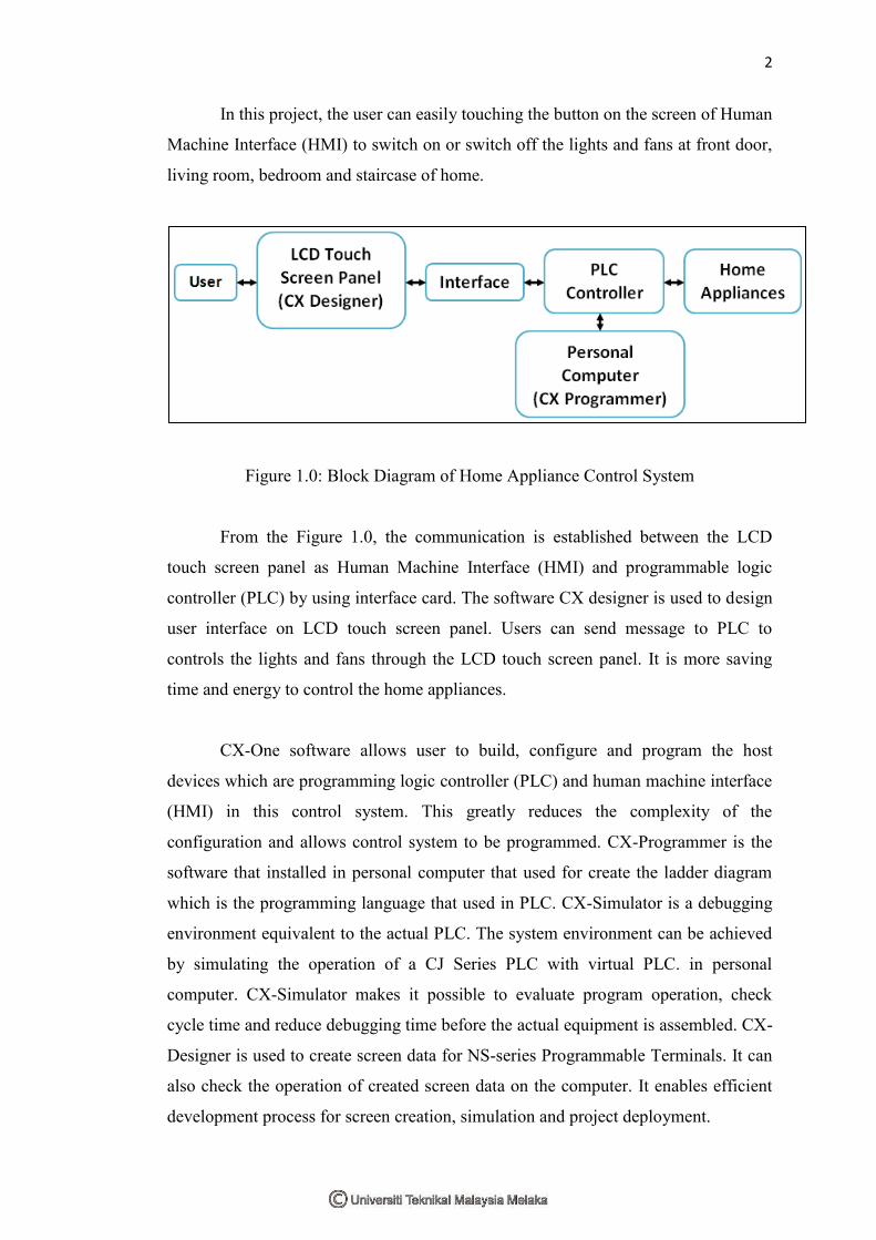
In this project, the user can easily touching the button on the screen of Human
Machine Interface (HMI) to switch on or switch off the lights and fans at front door,
living room, bedroom and staircase of home.
Figure 1.0: Block Diagram of Home Appliance Control System
From the Figure 1.0, the communication is established between the LCD
touch screen panel as Human Machine Interface (HMI) and programmable logic
controller (PLC) by using interface card. The software CX designer is used to design
user interface on LCD touch screen panel. Users can send message to PLC to
controls the lights and fans through the LCD touch screen panel. It is more saving
time and energy to control the home appliances.
CX-One software allows user to build, configure and program the host
devices which are programming logic controller (PLC) and human machine interface
(HMI) in this control system. This greatly reduces the complexity of the
configuration and allows control system to be programmed. CX-Programmer is the
software that installed in personal computer that used for create the ladder diagram
which is the programming language that used in PLC. CX-Simulator is a debugging
environment equivalent to the actual PLC. The system environment can be achieved
by simulating the operation of a CJ Series PLC with virtual PLC. in personal
computer. CX-Simulator makes it possible to evaluate program operation, check
cycle time and reduce debugging time before the actual equipment is assembled. CX-
Designer is used to create screen data for NS-series Programmable Terminals. It can
also check the operation of created screen data on the computer. It enables efficient
development process for screen creation, simulation and project deployment.
3
1.2 Objectives
The main objectives of this project:
i. To design a home appliance control system by using programming
logic controller (PLC).
ii. To provide a system to enable advanced home control capabilities
such as view and change states of the lamps and fans at home.
iii. To saving time and effort by having home automatically do routine
functions.
iv. To simplify human life because can control all home appliances by
one device only.
1.3 Problem Statements
. There are many home appliances in our living space, need to make them
intelligent so as to make living life more safety, convenient and comfortable for users
especially for older and disabled people who more reliance on home care. If the area
of home is bigger, is not easily to control home appliances at different location in the
home. It will be wasting time and energy to controls all home appliances. Many
electrical switches and devices need to control all the home appliances causes higher
cost in hardware wiring. Sometimes, many home appliances also cause waste
electricity if users forget to switch off the electrical devices.
1.4 Scopes of Work
The project is covered few parts, which are:
i. Programming Logic Controller (PLC) used for control the light and
fan.
ii. Connect the PLC with Personal Computer by using RS232 serial port.
iii. Study on Ladder Diagram which is the programming language of PLC.
iv. Design the ladder diagram in CX Programmer for specific instruction
or function for controlling system.
4
v. CX Designer from CX-One Software is used to create the Human
Machine Interface (HMI).
vi. Design the user interface which can view, change, reset and save
states of lamp and fan.
vii. Build the communication between LCD Touch Screen with PLC by
using Interface Card.
1.5 Importance of the Project
In this project, the home appliances control system is designed to allow users
to view and control home appliances of varying kinds by using one device only. It is
more saving cost because can reduce the cost of hardware wiring. Memory of
programming logic controller (PLC) can be getting bigger and used to store the
program of control system. It is more efficiency to control many kinds of home
appliances especially in the bigger area of home. Users can controls the home
appliances by touching the buttons on the LCD panel of human machine interface
(HMI). User interface of LCD panel display the states of home appliances at
different location of home. It is more saving time and energy to view and change the
state of home appliances.
1.6 Project Methodology
The objectives must be achieved to obtain a successful outcome in this
project. From the beginning of this project is having discussion with supervisor, need
to study the project have been designed by other company or person. For the
following stage, all the information related to hardware and software components
information is seeking and the most suitable would be selected for used in the project.
If the outputs of this system did not fulfill the desired output, so the troubleshooting
would be carry out until it reaches the project requirements. Further details
explanation of the project methodology will be explained in Chapter III.
5
1.7 Report Structure
This report is documentary delivering the ideas generated, concepts applied,
activities done and the outcome of the project. It consists of five chapters. The
description of this report as following:
Chapter I: Introduction
The first chapter is introduces the general overview of the project. In this chapter, it
states the background, objectives, scope of work, importance, problem statement and
methodology of this project.
Chapter II: Literature Review
This chapter discusses the research of study related to the project. The information of
research is obtained from journal, book reference, lecturer notes and etc. This chapter
is performed and document about the theoretical concept applied in completing this
project.
Chapter III: Project Methodology
This chapter is identifies the materials, equipments or apparatus are used in this
project. It also determines the method or procedures are implemented in this project.
Flow chart and Gantt chart are used to design the flow of completing the project.
Chapter IV: Results and Discussions
It shows the current results or progress of the project. The results are explained with
the aid of figures and tables.
Chapter V: Conclusion and Recommendation
It is the final part of the thesis which concludes the Final Year Project. It is includes
the application of the project and the recommendation that can be implemented for
future references.
References
The list of references is determined.

CHAPTER II
LITEATURE REVIEW
This chapter will discuss about literature discourse and the review of smart
home appliances control system. This chapter is regarding the background study of
the project to perform and documented about the theoretical concept applied in
completing the project. The reason of choosing the specific software and hardware
also included in this chapter.
2.1 Introduction
Literature review are based in information obtained from valid sources such
as books, articles of relevance, publisher paper or any other source deemed
appropriate.
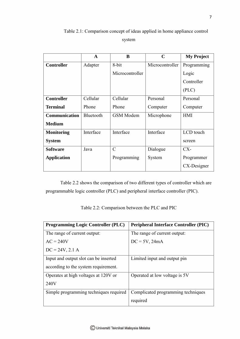
2.2 Comparison
The Table 2.1 shows the comparison of different project with the concept of
ideas that applied in home appliances control system. The information is obtained
from the IEEE journals.
7
Table 2.1: Comparison concept of ideas applied in home appliance control
system
A B C My Project
Controller Adapter 8-bit
Microcontroller
Microcontroller Programming
Logic
Controller
(PLC)
Controller
Terminal
Cellular
Phone
Cellular
Phone
Personal
Computer
Personal
Computer
Communication
Medium
Bluetooth GSM Modem Microphone HMI
Monitoring
System
Interface Interface Interface LCD touch
screen
Software
Application
Java C
Programming
Dialogue
System
CX-
Programmer
CX-Designer
Table 2.2 shows the comparison of two different types of controller which are
programmable logic controller (PLC) and peripheral interface controller (PIC).
Table 2.2: Comparison between the PLC and PIC
Programming Logic Controller (PLC) Peripheral Interface Controller (PIC)
The range of current output:
AC = 240V
DC = 24V, 2.1 A
The range of current output:
DC = 5V, 24mA
Input and output slot can be inserted
according to the system requirement.
Limited input and output pin
Operates at high voltages at 120V or
240V
Operated at low voltage is 5V
Simple programming techniques required Complicated programming techniques
required
8
Less wiring More wiring
High cost Low cost
2.3 Programming Logic Controller (PLC)
A programmable logic controller (PLC) is a solid state user programmable
control system with function to control logic, sequencing, timing, arithmetic data
manipulation and counting capabilities.
2.3.1 Definition
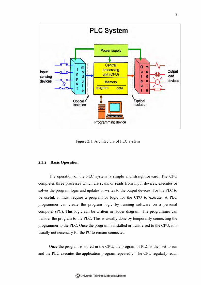
From the Figure 2.1, PLC can be viewed as industrial computer that has a
central processing unit (CPU), memory, input output interface and a programming
device. The CPU provides the intelligence of the controller. It accepts data, status
information from various sensing devices, executes the user control program stored
in the memory and gives appropriate output commands to devices.
Input/output interface is the communication link between field devices and
the controllers. The processor can sense and measure the physical quantities
regarding a machine or process through these interface. The CPU issues command to
output devices. The programmer unit used to enter the application program which
often uses simple user friendly logic.
9
Figure 2.1: Architecture of PLC system
2.3.2 Basic Operation
The operation of the PLC system is simple and straightforward. The CPU
completes three processes which are scans or reads from input devices, executes or
solves the program logic and updates or writes to the output devices. For the PLC to
be useful, it must require a program or logic for the CPU to execute. A PLC
programmer can create the program logic by running software on a personal
computer (PC). This logic can be written in ladder diagram. The programmer can
transfer the program to the PLC. This is usually done by temporarily connecting the
programmer to the PLC. Once the program is installed or transferred to the CPU, it is
usually not necessary for the PC to remain connected.
Once the program is stored in the CPU, the program of PLC is then set to run
and the PLC executes the application program repeatedly. The CPU regularly reads