holset hx25/25w/27w - speed trapp consulting · hx25/25w/27w service repair manual introduction...
TRANSCRIPT

Holset HX25/25W/27WService Repair Manual
Copyright 2007, Cummins Turbo Technologies Ltd. All rights reserved.VGT, Command Valve and Super MWE are trade marks of Cummins Turbo Technologies Ltd.Holset and the Holset Logo are registered trade marks of Cummins Turbo Technologies Ltd.Cummins and the Cummins logo are registered trade marks of Cummins Inc.

HX25/25W/27W Service Repair Manual Foreword
ForewordThis publication was written to assist with turbocharger installation, maintenance and overhaul. It is not awarranty of any kind expressed or implied.
The specifications and procedures in this manual are based on information in effect at the time of publication.Holset Service reserves the right to make any changes at any time without obligation. If differences are foundbetween your turbocharger and the information in this manual, contact your local Holset approved agent.
The latest technology and the highest quality standards are used in the manufacture of Holset Turbochargers.When replacement parts are needed, we recommend using only genuine Holset parts.

HX25/25W/27W Service Repair Manual Table of Contents
Table of Contents1: Introduction
About the Manual . . . . . . . . . . . . . . . . . . . . . . . . . . . . . . . . . . . . . . . . . . . . . . . . . . 1:1
How to Use the Manual . . . . . . . . . . . . . . . . . . . . . . . . . . . . . . . . . . . . . . . . . . . . . 1:1
How to Order Holset Original Parts. . . . . . . . . . . . . . . . . . . . . . . . . . . . . . . . . . . . . 1:1
Description and Operation of Turbocharger . . . . . . . . . . . . . . . . . . . . . . . . . . . . 1:2
General Information . . . . . . . . . . . . . . . . . . . . . . . . . . . . . . . . . . . . . . . . . . . 1:2
Introduction to Turbocharger Matching . . . . . . . . . . . . . . . . . . . . . . . . . . . . . 1:2
Notes, Cautions and Warnings . . . . . . . . . . . . . . . . . . . . . . . . . . . . . . . . . . . 1:3
Installation Data . . . . . . . . . . . . . . . . . . . . . . . . . . . . . . . . . . . . . . . . . . . . . . . . . . 1:4
Installation Checklist . . . . . . . . . . . . . . . . . . . . . . . . . . . . . . . . . . . . . . . . . . . . . . 1:5
Symbols . . . . . . . . . . . . . . . . . . . . . . . . . . . . . . . . . . . . . . . . . . . . . . . . . . . . . . . . 1:6
2: Component Identification
Turbocharger Identification . . . . . . . . . . . . . . . . . . . . . . . . . . . . . . . . . . . . . . . . . 2:1
Dataplate and CHRA (Core) of Turbocharger . . . . . . . . . . . . . . . . . . . . . . . . 2:1
Installation Options . . . . . . . . . . . . . . . . . . . . . . . . . . . . . . . . . . . . . . . . . . . . 2:2
Exploded Views . . . . . . . . . . . . . . . . . . . . . . . . . . . . . . . . . . . . . . . . . . . . . . . . . . 2:4
Component List . . . . . . . . . . . . . . . . . . . . . . . . . . . . . . . . . . . . . . . . . . . . . . . . . . 2:6
Purchasable Service Tools . . . . . . . . . . . . . . . . . . . . . . . . . . . . . . . . . . . . . . . . . 2:8
3: Troubleshooting and DiagnosisFault Finding Chart . . . . . . . . . . . . . . . . . . . . . . . . . . . . . . . . . . . . . . . . . . . . . . . 3:1
4: Component Testing and ReplacementService Tools . . . . . . . . . . . . . . . . . . . . . . . . . . . . . . . . . . . . . . . . . . . . . . . . . . . . 4:1
On Engine Checks . . . . . . . . . . . . . . . . . . . . . . . . . . . . . . . . . . . . . . . . . . . . . . . . 4:2
Bearing Clearance . . . . . . . . . . . . . . . . . . . . . . . . . . . . . . . . . . . . . . . . . . . . . . . . 4:5
Turbine and Compressor Housings. . . . . . . . . . . . . . . . . . . . . . . . . . . . . . . . . . . 4:6
Cleaning of Housings. . . . . . . . . . . . . . . . . . . . . . . . . . . . . . . . . . . . . . . . . . . . . . 4:9
Re-assembly of Housings . . . . . . . . . . . . . . . . . . . . . . . . . . . . . . . . . . . . . . . . . . 4:11
Wastegate Actuator Checks . . . . . . . . . . . . . . . . . . . . . . . . . . . . . . . . . . . . . . . . 4:14
Wastegate Actuator Removal . . . . . . . . . . . . . . . . . . . . . . . . . . . . . . . . . . . . . . . 4:15
Wastegate Mechanism Check . . . . . . . . . . . . . . . . . . . . . . . . . . . . . . . . . . . . . . . 4:16
Wastegate Actuator Replacement. . . . . . . . . . . . . . . . . . . . . . . . . . . . . . . . . . . . 4:18
5: Turbocharger Service and OverhaulService Tools . . . . . . . . . . . . . . . . . . . . . . . . . . . . . . . . . . . . . . . . . . . . . . . . . . . . 5:1
Disassembly . . . . . . . . . . . . . . . . . . . . . . . . . . . . . . . . . . . . . . . . . . . . . . . . . . . . . 5:2
Component Cleaning . . . . . . . . . . . . . . . . . . . . . . . . . . . . . . . . . . . . . . . . . . . . . . 5:6
Inspection and Testing. . . . . . . . . . . . . . . . . . . . . . . . . . . . . . . . . . . . . . . . . . . . . 5:8
Reassembly . . . . . . . . . . . . . . . . . . . . . . . . . . . . . . . . . . . . . . . . . . . . . . . . . . . . . 5:13
6: Service Data SheetsHX Range Service Data Sheets . . . . . . . . . . . . . . . . . . . . . . . . . . . . . . . . . . . . . . . 6:1

HX25/25W/27W Service Repair Manual Introduction
1:1
About the ManualThe procedures in this manual were developed to instruct in the correct overhaul of the designated Holsetturbocharger range for optimum performance and minimum maintenance operation.
How to Use the ManualThe manual is split into sections designed to provide service information in a logical sequence. The manualcontains links to help the user navigate between relevant sections. Users who are unfamilier with navigating inPDF documents are refered to Navigating in PDF documents in the Adobe® Acrobat® Reader™ help file.
Contents is an interactive page with links to all the sections. It can be accessed from any pagein the manual by clicking this icon.
Section 1 defines the layout of the manual, introduces the reader to the operation of the turbochargerand presents important installation guidelines.
Sections 2, 3 and 4 concentrate on Turbocharger Component Identification, Troubleshooting andDiagnosis, Component Testing and Replacement.
Section 5 identifies the Service and Overhaul procedures to be followed in the unlikley event of a major turbocharger malfunction.
Section 6 quantifies build data to ensure the turbocharger will continue to operate to Holset Servicestandard on completion of overhaul.
Manual sections 1 to 5 where applicable, appear as a self extracting compressed file which is organisedaccording to the steps needed to most easily and correctly maintain the operation of the turbocharger. Usersare required to download this file to hard disk. Section 6 has its own file identity and resides atwww.holset.co.uk. so that Holset can update the Service Data as changes occur. The links between manualand service data are active only when the user is connected to the Internet.
Chapter 6 has an expiry date to encourage users to discard outdated saved or printed versions and alwaysaccess the latest information available at www.holset.co.uk.
When using the manual on-line this icon will link to Holset’s website to help find your nearest agentfor advice and how to order Holset original parts.
How to Order Holset Original PartsTo make sure of optimum performance, certain items must be discarded during disassembly and replaced withnew for re-assembly. These items are indicated in the Service and Overhaul section with the use of a *symbol.All items showing a * are available in a basic overhaul kit.
To get the correct parts for your turbocharger, refer to the ‘component identification’ section of this manual tohelp you find the following information:
1) Refer to the exploded view and component list to define the major components to be replaced.2) Refer to the turbocharger’s dataplate which will be found on the compressor cover or wastegate
actuator to define the identifying information about your turbocharger build standard.3) Contact your local Holset agent with componant identification nos. and dataplate assembly no., serial
no. and turbocharger type.4) With this information, your local agent can provide you with the optimum kit of parts for re-assembling
your turbocharger for continued long life operation.

HX25/25W/27W Service Repair Manual Introduction
Description and Operation of Turbocharger
1:2
General InformationA turbocharger is a mechanical device which uses the engine’s exhaust gases to force more air into the enginecylinders. Hot exhaust gas energy is used to turn a turbine wheel and shaft. At the other end of the shaft is thecompressor impeller (or compressor wheel), which draws in air and forces it into the engine cylinders.
Supplying increased air mass flow to the engine provides improved engine performance, lower exhaust smokedensity, improved operating economy and altitude compensation. The turbocharger has proven to be one of themost beneficial devices for improving engine performance. It performs its job very well, as long as it is properlycared for.
Introduction to Turbocharger MatchingThe need for optimised matching over the engine speed rangeA standard turbocharger can be perfectly matched to only one particular engine condition, eg maximum torquespeed or maximum load speed. At this engine speed, the turbocharger supplies the optimum mass of air togive the required air/fuel ratio. At other speeds the air/fuel ratio cannot be held at the optimum hence fuelconsumption and emission levels worsen.
Engine emission legislations have forced manufacturers to improve their engine efficiencies, particularly at lowspeeds where low air/fuel ratios cause high smoke levels.
The Holset turbocharger is carefully matched to meet the required engine characteristics during applicationengineering. It is important that this match is maintained by using only Holset original turbine and compressorparts.
The importance of correctly servicing the turbochargerA turbocharger requires accurate assembly at point of manufacture. It is very important to adhere to settinglimits when servicing the turbocharger, as failure to do so could result in turbocharger or engine failure.
Effects of wrong matchPossible consequences if turbocharger boost pressure is too low:-
• Engine runs fuel rich • Fuel consumption increase
• Exhaust temperature increase • Smoke levels increase
• Hydrocarbon levels increase • Risks of failing emissions tests
• High cylinder temperature risksdamage to engine pistons
Possible consequences if turbocharger boost pressure is too high:-
• Engine runs fuel weak (lean) • Nitrous oxide levels increase
• Excessive boost overspeeds • Turbocharger bearing failure andturbocharger wheel fatigue problems
• Increased cylinder pressure risks damage • Intercooler load increases causing engineto engine head gasket, pistons and valves to overheat, risking piston damage

NoteHolset Service receives many turbocharger returns that are no fault found. Before assuming the turbocharger is not performing to specification always refer to the engine diagnostic system and the troubleshootingdiagnostic procedures of this manual.
HX25/25W/27W Service Repair Manual Introduction
1:3
Notes, Cautions and Warnings
Notes, Cautions and Warnings are used in this manual to emphasise important or critical instructions.
NoteInformation which is essential to highlight.
CautionMaintanence or Service procedures which if not strictly followed, will result in damage or destruction of the turbocharger.
WarningMaintanence or Service procedures which if not correctly followed will result in personal injury or loss of life.
WarningTurbocharger surface temperature during operation can achieve 700°C (1300°F). The designated turbocharger range weighs up to 4.8 kg (10.6 lb) and is fitted with external parts that are sensitive to manual handling.
CautionThis turbocharger requires a new standard of balancing process on rebuild using a proprietary vibrationsorting rig (VSR).The turbocharger will not have any co-relation marks. If you intend to overhaul/repair the turbocharger, and do not have access to a VSR machine, we recommend that you send the reassembled core in appropriate packaging to protect the turbine and compressor blades to an approved Holset agent with VSR facilities.As the results of vibration based tests are rig specific, the balance limits shown in Holset’s Service Data Sheets are advisory only. Refer to repair agent to warrant durability, noise and vibration level of the specific VSR balancing process used. If you are in any doubt regarding the balancing process, please contact the local Holset agent for assistance.
WarningSome parts are manufactured in Viton that requires special treatment in the case of repair and service after fire.
NoteHolset turbochargers can be remanufactured using recovered parts. Where it is necessary to dispose of components or whole turbochargers, an environmentally responsible process such as recycling should be used, with due regard to local laws.
HX25/25W/27W Service Repair Manual Introduction
Installation Data
1:4
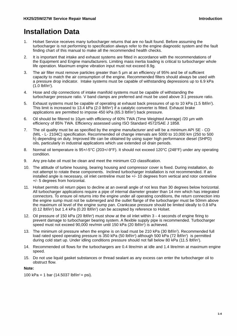
1. Holset Service receives many turbocharger returns that are no fault found. Before assuming the turbocharger is not performing to specification always refer to the engine diagnostic system and the fault finding chart of this manual to make all the recommended health checks.
2. It is important that intake and exhaust systems are fitted in accordance with the recommendations of the Equipment and Engine manufacturers. Limiting mass inertia loading is critical to turbocharger whole life operation. Maximum engine vibration input must not exceed 8.9g.
3. The air filter must remove particles greater than 5 µm at an efficiency of 95% and be of sufficient capacity to match the air consumption of the engine. Recommended filters should always be used with a pressure drop indicator. Intake systems must be capable of withstanding depressions up to 6.9 kPa (1.0 lbf/in2).
4. Hose and clip connections of intake manifold systems must be capable of withstanding the turbocharger pressure ratio. V band clamps are preferred and must be used above 3:1 pressure ratio.
5. Exhaust systems must be capable of operating at exhaust back pressures of up to 10 kPa (1.5 lbf/in2). This limit is increased to 13.4 kPa (2.0 lbf/in2) if a catalytic converter is fitted. Exhaust brake applications are permitted to impose 450 kPa (65.3 lbf/in2) back pressure.
6. Oil should be filtered to 10µm with efficiency of 60% TWA (Time Weighted Average) /20 µm withefficiency of 85% TWA. Efficiency assessed using ISO Standard 4572/SAE J 1858.
7. The oil quality must be as specified by the engine manufacturer and will be a minimum API SE - CD (MIL - L- 2104C) specification. Recommended oil change intervals are 5000 to 10,000 km (250 to 500 h) depending on duty. Improved life can be obtained by using super high performance diesel (SHPD) oils, particularly in industrial applications which use extended oil drain periods.
8. Normal oil temperature is 95+/-5°C (203+/-9°F). It should not exceed 120°C (248°F) under any operating condition.
9. Any pre-lube oil must be clean and meet the minimum CD classification.
10. The attitude of turbine housing, bearing housing and compressor cover is fixed. During installation, do not attempt to rotate these components. Inclined turbocharger installation is not recommended. If an installed angle is necessary, oil inlet centreline must be +/- 10 degrees from vertical and rotor centreline +/- 5 degrees from horizontal.
11. Holset permits oil return pipes to decline at an overall angle of not less than 30 degrees below horizontal.All turbocharger applications require a pipe of internal diameter greater than 14 mm which has integrated connectors. To ensure oil returns into the engine under all operating conditions, the return connection into the engine sump must not be submerged and the outlet flange of the turbocharger must be 50mm above the maximum oil level of the engine sump pan. Crankcase pressure should be limited ideally to 0.8 kPa (0.12 lbf/in2) but 1.4 kPa (0.20 lbf/in2) can be accepted by reference to Holset.
12. Oil pressure of 150 kPa (20 lbf/in2) must show at the oil inlet within 3 - 4 seconds of engine firing to prevent damage to turbocharger bearing system. A flexible supply pipe is recommended. Turbocharger speed must not exceed 90,000 rev/min until 150 kPa (20 lbf/in2) is achieved.
13. The minimum oil pressure when the engine is on load must be 210 kPa (30 lbf/in2). Recommended full load rated speed operating pressure is 350 kPa (50 lbf/in2) although 500 kPa (72 lbf/in2) is permitted during cold start up. Under idling conditions pressure should not fall below 80 kPa (11.5 lbf/in2).
14. Recommended oil flows for the turbochargers are 0.4 litre/min at idle and 1.4 litre/min at maximum enginespeed.
15. Do not use liquid gasket substances or thread sealant as any excess can enter the turbocharger oil to obstruct flow.
Note:
100 kPa = 1 bar (14.5037 lbf/in2 = psi).

HX25/25W/27W Service Repair Manual Introduction
Installation Checklist
1:5
1. Always understand why the original turbocharger needs replacing before fitting another unit.
2. Check the turbocharger dataplate to ensure the Part No. is correct for the engine/application.
3. Check the engine exhaust, intake and aftercooler systems are clean and without obstruction i.e. free from oil, gasket pieces, dust/dirt/carbon or foreign objects.
4. Replace the oil and air filters using replacement parts specified by the equipment manufacturer.
5. Change the engine oil using the type specified by the engine manufacturer.
6. Check that the turbocharger oil inlet and drain pipes and connectors are clean, free from obstruction and will not leak under pressure.
7. Check that the coolant pipes of water cooled bearing housing applications and connectors are clean, free from obstruction and will not leak under pressure.
8. To pre-lube the turbocharger bearings, pour some clean engine oil into the oil inlet and rotate the turbocharger rotor assembly by hand.
9. Check that the exhaust manifold flange is flat and undamaged. Mount the turbocharger on the flange and check that the turbine inlet gasket fits properly without obstructing the gas passages.
10. Assemble the air intake and boost outlet connections. Check that the connections are well made and will not leak in use.
11. Check the exhaust system is fitted using the original mounting arrangement provided by the equipment manufacturer. Always re-fit any supports/brackets back in position to ensure the system is correctly supported.
12. Assemble the exhaust system to the turbine housing outlet. Check that the gasket/connection is well made and will not leak in use.
13. Assemble any coolant pipes and check that the connections are well made, without obstruction and will not leak in use.
14. Assemble the turbocharger oil inlet pipe and check that the connection is clean, well made and will not leak in use.
15. Check all clamps and fasteners are correctly tightened to the torque recommended by the equipment manufacturer.
16. Make any ECU checks recommended by the engine manufacturer.
17. Crank the engine WITHOUT firing until engine oil flows out of the turbocharger drain flange.
18. Assemble the oil drain pipe and check that the connection is well made, without obstruction and will not leak in use.
19. Start the engine and run at idle speed for approximately 1 minute so that the oil supply system is fully operational.
20. Accelerate the engine and check that there are no leaks/obstructions of air/oil/coolant/gas under pressure.
21. Check that no hose or connection deforms under normal operation.
22. Before switching off the engine, leave it running at idle speed for at least 1 minute to cool the turbine.

Symbole - DeutschIn diesem Handbuch werden die folgenden Symbole verwendet, die wesentliche Funktionen hervorheben. DieSymbole haben folgende Bedeutung:
WARNUNG - Unterhaltungs und Wartungsverfahren müssen genau befolgt werden, da einNichtbeachten zu Personenschäden oder tödlichen Verletzungen führt.
ACHTUNG - Falls Unterhaltungs und Wartungsverfahren nicht genau beachtet werden, kann derTurbolader dadurch beschädigt oder zerstört werden.
AUSBAU bzw. ZERLEGEN.
EINBAU bzw. ZUSAMMENBAU.
INSRPEKTION erforderlich.
Teil oder Baugruppe REINIGEN.
DIMENSION - oder ZEITMESSUNG.
Teil oder Baugruppe ÖLEN.
WERKZEUGGRÖSSE wird angegeben.
ANZUG auf vorgeschriebenes Drehmoment erforderlich.
Sicherstellen, daß die AUSWUCHTMARKEN an der Rotor-Baugruppe richtig ausgerichtet sind.
Elektrische MESSUNG DURCHFÜRHREN.
Weitere Informationen an anderer Stelle bzw. in anderen Handbüchern.
Schutzkleidung muß immer getragen werden.
Deutet an, daß Teile schwer sein können.
Website-Verzeichnis mit Ihrem nächsten Holset-Händler.
Gehe zu Inhalt
HX25/25W/27W Service Repair Manual Introduction
Symbols
1:6
KG

Symbols - EnglishThe following group of symbols have been used in this manual to help communicate the intent of theinstructions. When one of the symbols appears, it conveys the meaning defined below.
WARNING - Serious personal injury or extensive property damage can result if the warninginstructions are not followed.
CAUTION - Minor personal injury can result or a part, an assembly or the engine can be damaged ifthe caution instructions are not followed.
Indicates a REMOVAL or DISASSEMBLY step.
Indicates an INSTALLATION or ASSEMBLY step.
INSPECTION is required.
CLEAN the part or assembly.
PERFORM a mechanical or time MEASUREMENT.
LUBRICATE the part or assembly.
Indicates that a WRENCH or TOOL SIZE will be given.
TIGHTEN to a specific torque.
Ensure that the BALANCE MARKS on the rotor assembly are in alignment
PERFORM an electrical MEASUREMENT.
Refer to another location in this manual or another publication for additional information.
Please wear protective clothing at all times.
Indicates components may be heavy.
Website access to find your nearest Holset Agent.
Go to contents
HX25/25W/27W Service Repair Manual Introduction
1:7
KG

Simbolos - EspañolLos simbolos siguientes son usados en estes manual para clarificar el proceso de las instrucciones. Cuadoaparece uno de estos simbolos, su significado se espcifica en la parte inferior.
ADVERTENCIA – Procedimientos de Mantenimiento o Servicio que al no seguirse resultarán endaños personales o pérdida de vida.
ATENCION – Procedimientos de Mantenimiento o Servicio que al no seguirse al pie de la letra,resultarán en el daño o la destrucción del turbosobrealimentador.
Indica un paso de REMOCION o DESMONTAJE.
Indica un paso de INSTALACION o MONTAJE.
Se requiere INSPECCION.
LIMPIESE la pieza o el montaje.
Ejecutese una MEDICION mec·nica o del tiempo.
LUBRIQUESE la pieza o el montaje.
Indica que se dar· una LLAVE DE TUERCAS o el TAMA—O DE HERRAMIENTA.
APRIETESE hasta un par torsor especifico.
Ceriórese de que est·n alineadas las marcas de balance en el rotor.
EJECUTESE una MEDICION eléctrica.
Para información adicional refiérase a otro emplazamiento de este manual o a otra publicaciónanterior.
Favor de siempre llevar ropa protectora.
Indica que los componentes pueden ser pesados.
Acceso a Sitio Web para localizar su agente Holset más cercano.
Ir a la tabla de materias
HX25/25W/27W Service Repair Manual Introduction
1:8
KG

Symboles - FrançaisLes symboles suivants sont utilisés dans ce manuel pour aider à communiquer le but des instructions. Quandl’un de ces symboles apparait, il évoque le sens défini ci-dessous:
ATTENTION DANGER - Procédures de maintenance ou d’entretien qui, si elles ne pas observéescorrectement, auront pour résultat des lésions corporelles ou un décès.
MISE EN GARDE - Procédures de maintenance ou d’entretien qui, si elles ne sont pas observéesstrictement, auront pour résultat de causer des dégâts au turbocompresseur ou de conduire à sadestruction.
Indique une opération de DEPOSE.
Indique une opération de MONTAGE.
L’INSPECTION est nécessaire.
NETTOYER la pièce ou l’ensemble.
EFFECTUER une MESURE mécanique ou de temps.
GRAISSER la pièce ou l’ensemble.
Indique qu’une DIMENSION DE CLE ou D’OUTIL sera donnée.
SERRER à un couple spécifique.
S’assurer que les repères d’équilibrage sur l’ensemble de rotor sont alignés.
EFFECTUER une MEASURE électrique.
Se reporter à un autre endroit dans ce manuel ou à une autre publication pour obtenir desinformation plus complètes.
Il faut toujours mettre vêtements de protection.
Indique que les composants peuvent être lourds.
Accès au site Web pour trouver l’agent Holset le plus proche.
Aller au sommaire
HX25/25W/27W Service Repair Manual Introduction
1:9
KG

HX25/25W/27W Service Repair Manual Introduction
1:10
Símbolos - PortuguêsOs símbolos a seguir serão utilizados neste manual para facilitar a comunicação das instruções e seuesignificados estão déscritos abaixo.
ATENÇÃO - Os procedimentos de Manutenção ou Serviços que não forem seguidos correctamenteresultarão em ferimentos pessoais ou riscos de vida.
AVISO - Os procedimentos de Manutenção ou Serviço que não forem rigorosamente seguidosresultarão em danos ou destruição do carregador turbo.
Indica um passe de DESMONTAGEM.
Indica um passo de MONTAGEM.
Requer inspeção.
LIMPE a peça ou conjunto.
Requer Medição mecãnica ou de tempo.
LUBRIFIQUE a peça ou o conjunto.
Indica necessidade de APERTO.
TORQUEAR de acordo com o especificado.
Assegure-se de que as MARCAS DE BALANCEAMENTO do conjunto eixorotor estejam alinhadas.
Requer medição ELÉTRICA.
Procure em outra seção deste manual ou em publicação par obter informações adicionais
Por favor, sempre utilize EPI (Equipamento de Protecao Individual)
Indica que os componentes podem estar pesados.
Visite o Website para encontrar o seu Agente Holset mais perto.
Vá para Conteúdo
KG

Turbocharger Identification
HX25/25W/27W Service Repair Manual Component Identification
2:1
Dataplate
Center Housing Rotating Assembly (CHRA) (2)
35XXXXXXYYMMXXXXX
HX27WNoteDataplates will be fitted to the compressor housing (8). The information from the dataplate must be quoted for service and parts support.

HX25/25W/27W Service Repair Manual Component Identification
2:2
Installation Options
Type A HX27W
Type B HX25
Type C HX25W

HX25/25W/27W Service Repair Manual Component Identification
2:3
Installation Options
Type D - HX25W
Type E - HX25
Type F - HX25W

HX25/25W/27W Service Repair Manual Component Identification
Exploded View - HX27W Type A
2:4
74
106 60
73
76
75
75
77
96
81
28
43
113114
4
761
66
33
38
60
12
1164
11
91
53
41
36
613
31
1632
62
5
8
NoteExploded views represent a generic build standard. Parts may be added or subtracted in specific applications.
HX25/25W/27W Service Repair Manual Component Identification
2:5
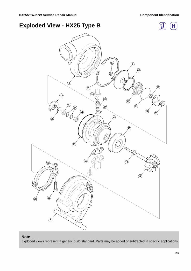
Exploded View - HX25 Type B
113
114
4
761
66
16
38
60
12
1164
11
91
41
36
53
6
13
5
8
3133
32
43
28
62
96
NoteExploded views represent a generic build standard. Parts may be added or subtracted in specific applications.

HX25/25W/27W Service Repair Manual Component Identification
Component List - HX25/25W/27W
2:6
Item No. Description Quantity
All Applications
1 Repair Kit CHRA (Core)* 1
2 CHRA (Core) 1
4 Bearing Housing 1
5 Turbine Housing 1
6 Assembly, Turbine Wheel 1
7 Compressor Wheel 1
8 Compressor Housing 1
11 Journal Bearing* 2
12 Thrust Bearing* 1
13 Split Ring Seal, Turbine* 1
16 Split Ring Seal, Compressor* 1
28 V-Band Clamp, Turbine 1
31 Oil Slinger 1
32 O-Ring Seal, Bearing Housing* 1
33 Oil Baffle 1
36 Thrust Collar 1
38 Heat Sheild 1
41 O-Ring Seal, Compressor Housing* 1
43 Oil Seal Plate 1
53 Gasket, Oil Outlet 1
60 Plain Washer 1
61 Locknut, Compressor Wheel 1
62 Locknut, V-Band 1
64 Retaining Ring, Bearing* 2
66 Retaining Ring, Insert 1
91 Retaining Ring, Compressor Housing 1
96 Screw, V-band 1
113 Adaptor, Oil Inlet 1
114 O-Ring Seal, Oil Inlet 1

HX25/25W/27W Service Repair Manual Component Identification
Component List - HX25/25W/27W
2:7
Item No. Description Quantity
Wastegate Applications
74 Wastegate Kit comprising: 1
73 Actuator 1
75 Hose Clip 2
76 End Link, Assembly 1
77 Retaining Ring, End Link 1
106 Screw, Actuator 2
60 Plain Washer 2
128 Jam Nut 0/1
143 Breakoff Nut 0/1
81 Hose 1

HX25/25W/27W Service Repair Manual Component Identification
Purchasable Service Tools
2:8
The following special tools can be purchased from your local Authorised Repair Location. The use of thesetools is recommended and where necessary they are shown in the appropriate service procedure.
Service Tools
Part No. Tool Description Tool Illustration
CautionAll Service and Maintenance settings are shown in Holset’s Service Data Sheet. It is essential that thesesettings are used. Common tools found in mechanic’s tool box not included.
4027202 Wastegate Air Feed Adapter
4027203 Wastegate Air Feed Adapter
4027204 E-Clip Tool
3575186 Circlip Pliers

HX25/25W/27W Service Repair Manual Troubleshooting and Diagnosis
Fault Finding chart - All Applications
En
gin
e L
acks
Po
wer
Bla
ck E
xhau
st S
mo
ke
Blu
e E
xhau
st S
mo
ke
Hig
h O
il C
on
sum
pti
on
Turb
och
arg
er N
ois
y
En
gin
e R
un
nin
g H
ot
Po
or
Tran
sien
t R
esp
on
se
Sm
oke
Cyc
lic S
ou
nd
fro
m t
he
Turb
och
arg
er
Oil
Lea
k fr
om
Co
mp
ress
or
Sea
l
Oil
Lea
k fr
om
Tu
rbin
e S
eal
Dirty air cleanerClean or replace element according to manufacturer’s recommendations
Restricted compressor intake ductRemove restriction or replace damaged parts as required
Restricted air duct from compressor to intake manifoldRemove restriction or replace damaged parts as required
Restricted intake manifoldRefer to engine manufacturer’s manual and remove restriction
Air leak in feed from air cleaner to compressorReplace seals, gaskets or tighten fasteners as required
Air leak in feed from compressor to intake manifoldReplace seals, gaskets or tighten fasteners as required
Air leak between intake manifold and engineRefer to engine manufacturer’s manual and replace gaskets or tighten fasteners as required
Foreign object in exhaust manifold (from engine)Refer to engine manufacturer’s manual and remove obstruction
Restricted exhaust systemRemove restriction or replace damaged parts as required
Exhaust manifold cracked, gaskets blown or missingRefer to engine manufacturer’s manual and replace gaskets or damaged parts as required
Gas leak at turbine inlet/exhaust manifold jointReplace gasket or tighten fasteners as required
Gas leak in ducting after turbine outletRefer to engine manufacturer’s manual and repair leak
Restricted turbocharger oil drain lineRemove restriction or replace damaged parts as required
Restricted engine crankcase breatherRefer to engine manufacturer’s manual, clear restriction
Turbocharger bearing housing sludged or cokedChange engine oil and oil filter, overhaul or replace turbocharger as required
Fuel injection pump or fuel injectors incorrectly setRefer to engine manufacturer’s manual and replace or adjust faulty components as required
Engine valve timing incorrectRefer to engine manufacturer’s manual for correct settings and adjust as required
Worn engine piston rings or linersRefer to engine manufacturer’s manual and repair as required
Burnt valves and/or pistonsRefer to engine manufacturer’s manual and repair as required
Excessive dirt build up on compressor wheel and/or diffuser vanesContact your local approved dealer
Turbocharger damagedFind and correct cause of failure, or replace turbocharger as necessary
3:1

HX25/25W/27W Service Repair Manual Troubleshooting and Diagnosis
Fault Finding chart - Wastegate Applications
3:2
En
gin
e L
acks
Po
wer
Bla
ck E
xhau
st S
mo
ke
Blu
e E
xhau
st S
mo
ke
Hig
h O
il C
on
sum
pti
on
Turb
och
arg
er N
ois
y
En
gin
e R
un
nin
g H
ot
Po
or
Tran
sien
t R
esp
on
se
Sm
oke
Cyc
lic S
ou
nd
fro
m t
he
Turb
och
arg
er
Oil
Lea
k fr
om
Co
mp
ress
or
Sea
l
Oil
Lea
k fr
om
Tu
rbin
e S
eal
Failed actuator diaphragmReplace using correct Actuator Service Kit
Seized wastegate valve (in turbine housing)Free valve in accordance with details in the appropriate Holset publication replace complete turbine housing sub-assembly
Leaking actuator hoseReplace hose and clips
Wastegate mechanism set incorrectlyContact your approved Holset agent for correct setting procedure

Dial Gauge and Dial Gauge Adaptor-0+
1010
2020
3030
404050
MERCER
TYPE 20
Pressure Gauge Regulated Air SupplyMax 300 kPa (45 lbf/in2)
HX25/25W/27W Service Repair Manual Component Testing and Replacement
Service Tools
4:1
The following special tools are recommended to perform procedures in this manual. The use of these tools isshown in the appropriate procedure.
Part No. Tool Description Tool Illustration
Torque Wrench
CautionAll Service and Maintenance settings are shown in Holset’s Service Data Sheet. It is essential that thesesettings are used. Common tools found in mechanic’s tool box not included.

Oil LeakageBearing Housing M10 x 1.25
Pipe Fitting 11/16-16 UN (19 mm)
Replacement seals and adapters should be fittedwithout sealant as this can contaminate the oil. Torquetighten adaptor to value shown in Service Data Sheet.
It is important to avoid kinked pipes during servicingand subsequent operation.
HX25/25W/27W Service Repair Manual Component Testing and Replacement
On Engine Checks
4:2
M6 x 1.0
Replacement gaskets and flange fasteners should befitted without sealant as this can contaminate the oil.Torque tighten fasteners to value specified by enginemanufacturer.
All outlet pipes should be free flowing without kinks andsharp bends and decline at an overall angle not lessthan 30 degrees below the horizontal.
Closed crankcase ventilation systems may deposit oil inthe compressor housing. Where practical remove intakesystem pipework every 50,000 km (30,000 miles) tocheck housing, compressor wheel and inlet bafflecondition.
Always refer to Cleaning of Housings to cleanhousing. Rotor components can be cleaned using a nonmetallic bristle brush.
WarningThe oil inlet is pressurized and no service action should be taken with the engine running.
WarningOutlet oil is hot and no service action should be takenwith the engine running.
WarningAlways wear safety glasses during cleaning.

Exhaust Gas LeakageTurbine housing flange leakage will cause sootformation on the flange. Check exhaust manifold toflange seal ensuring fastener torque meets enginemanufacturer’s recommendation.
Check flange for cracks and ensure flatness is within0.1 mm (0.004 in).
Check turbine housing gasket for signs of damagewhich would cause leakage. Always replace damagedgaskets.
HX25/25W/27W Service Repair Manual Component Testing and Replacement
4:3
Visual ChecksCheck for cracked, bent or damaged compressor wheelblades.
Where practical, check for cracked, bent or damagedturbine wheel blades.
With intake system disconnected from compressorhousing, it may be possible to check visually for excessbearing axial and radial clearances.
If light finger pressure causes contact betweencompressor or turbine wheel with respective housing,replace turbocharger.
If in doubt, the turbocharger must be removed fromengine to check bearing clearance againstrecommended values shown in Service Data Sheet.
CautionNever attempt to straighten blades.
CautionNever attempt to straighten blades.

To check for wastegate actuator rod movement and airleakage on engine, follow the checking proceduredescribed in Wastegate Actuator Checks.
HX25/25W/27W Service Repair Manual Component Testing and Replacement
4:4
WarningNever attempt to check actuator using air supplied from a running engine.

Secure the turbine housing and check the thrustclearance using a dial gauge.
Ensure clearance is within MIN/MAX values shown onService Data Sheet.
If axial clearance does not meet specification refer toturbocharger Service and Overhaul to strip and rebuildthe CHRA (core).
HX25/25W/27W Service Repair Manual Component Testing and Replacement
Bearing Clearance
4:5
Check the radial movement at compressor impellernose using a dial gauge.
Ensure movement is within MIN/MAX TIR (TotalIndicator Reading) values shown onService Data Sheet.
If radial movement does not meet specification refer toturbocharger Service and Overhaul to strip and rebuildthe CHRA (core).

HX25/25W/27W Service Repair Manual Component Testing and Replacement
Turbine and Compressor Housings
4:6
Compressor HousingMark compressor housing, bearing housing andretaining ring to record correct orientation. This actionassists in re-assembling the pinned components anddefines orientation of the retaining ring.
Remove retaining ring, compressor housing usingsuitable circlip pliers.
Using a soft hammer, gently tap the compressorhousing off the bearing housing.
WarningAlways wear safety glasses when removing retaining ring.
CautionCompressor blades can be damaged easily when the compressor housing is removed. Do not bend the locating pin that aligns bearing housing and compressor housing.
NoteWhere fitted, it is necessary to remove the wastegateactuator before removing turbine or compressorhousings. Always ensure the end link is locked inthe correct pre-set position before removal. Refer toWastegate Actuator Removal for removal process.
WarningThe actuator rod may retract very quickly when freed from the lever arm. Keep fingers away from mechanism.
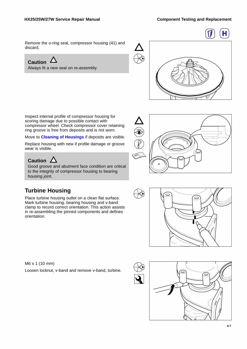
Remove the o-ring seal, compressor housing (41) anddiscard.
HX25/25W/27W Service Repair Manual Component Testing and Replacement
4:7
Inspect internal profile of compressor housing forscoring damage due to possible contact withcompressor wheel. Check compressor cover retainingring groove is free from deposits and is not worn.
Move to Cleaning of Housings if deposits are visible.
Replace housing with new if profile damage or groovewear is visible.
Turbine HousingPlace turbine housing outlet on a clean flat surface.Mark turbine housing, bearing housing and v-bandclamp to record correct orientation. This action assistsin re-assembling the pinned components and definesorientation.
M6 x 1 (10 mm)
Loosen locknut, v-band and remove v-band, turbine.
CautionAlways fit a new seal on re-assembly.
CautionGood groove and abutment face condition are criticalto the integrity of compressor housing to bearing housing joint.

Gently remove the CHRA (core) assembly from theturbine housing. If necessary use a soft hammer to freethe joint.
HX25/25W/27W Service Repair Manual Component Testing and Replacement
4:8
Cracking of the turbine housing inlet flange and inletduct generally requires turbine housing replacement.Acceptance and rejection guidelines are shown in thisillustration. If an exhaust gasket is available, alwaysensure that any cracks lie within its sealing area
Check turbine housing inlet flange flatness is within0.1 mm (0.004 in) before retaining component for re-use.
Check fastener hole diameter is not more than 1.5 mmlarger than the max. thread diameter of the fastener.
Cracking of the internal wall at the entry to the turbinewheel (tongue) is an acceptable service condition andthe turbine housing may be re-used.
CautionTurbine blades can be damaged easily when the turbine housing is removed. Do not bend the locating pin that aligns bearing housing and turbine housing.
CautionTurbine housings can exhibit cracking when subject toexcessive thermal and mechanical loads.
CautionWhere a crack will cause leakage to atmosphere the turbine housing must be replaced.

Visually inspect the parts to detect signs of burning andother conditions in order to obtain as much informationas possible before washing.
HX25/25W/27W Service Repair Manual Component Testing and Replacement
Cleaning of Housings
4:9
Soak the housings in a non-corrosive low flash pointmetal cleaner to loosen deposits.
Dry the components using compressed air.
Scale like deposits, if any, must be removed by using anon metallic bristle brush. After removing the deposits,re-wash and dry the components.
CautionSurfaces adjacent to turbine and compressor wheels on the stationary housings must be clean, smooth andfree from deposits.
WarningAlways wear safety glasses during cleaning.

HX25/25W/27W Service Repair Manual Component Testing and Replacement
4:10
It is permissible to bead blast the turbine housing ifchemical and brush cleaning is not effective.
WarningDo not bead blast Aluminium and Cast Iron components together.
CautionPrevent the bead spray impinging directly on turbine flange threads by masking or plugging.
WarningAlways wear safety glasses during cleaning.
CautionPrevent the bead spray impinging directly on the wastegate valve spindle (where fitted) as beads can penetrate the spindle bore, leading to spindle seizure.
After removing the deposits, re-wash and dry thecomponents.

Turbine HousingAlign marks applied to turbine housing, bearing housingand v-band clamp to establish component orientation.This action assists in re-assembling the pinnedcomponents.
HX25/25W/27W Service Repair Manual Component Testing and Replacement
Reassembly of Housings
4:11
Install CHRA (core) assembly to turbine housingmaking sure that it is correctly located on the alignmentpin fitted to turbine housing.
M6 x 1.0 (10 mm)
Locate v-band to orientation marks and apply molycoteanti-seize compound to the v-band screw threads.Insert screw and apply locknut. Torque tighten to valuespecified in Service Data Sheet.
Using a soft faced hammer, tap the v-band clamp threeor four times at equally spaced distances around itscircumference.
Re-tighten to specified torque.
Check for free rotation of the rotor assembly.
CautionTo protect compressor wheel blades, always assemble the compressor housing to CHRA (core) before refitting turbine housing.
CautionThe turbine wheel blades can easily be damaged when the CHRA (core) is installed.
CautionBe careful not to bend the location pin during assembly
WarningAlways wear safety glasses when refitting housings.

Compressor HousingLubricate new o-ring seal with clean engine oil andinsert into bearing housing groove.
HX25/25W/27W Service Repair Manual Component Testing and Replacement
4:12
Position retaining ring, compressor housing over thebearing housing with the chamfered face towards theturbine housing. Correctly align compressor housingusing disassembly orientation marks to ensure locationpin aligns with mating hole in bearing housing. Presscompressor housing into position taking care not to trapo-ring.
Turn turbocharger on to compressor inlet face. Refitretaining ring, compressor housing using suitable circlippliers.
Tap ends of retaining ring lightly with hammer and driftto ensure that the retaining ring is properly located intoits groove in the bearing housing.
CautionAways fit a new seal on re-assembly.
CautionCompressor blades can be damaged easily when compressor housing if being refitted.
NoteWhere the turbine housing is not already fitted to CHRA (core), the compressor housing should be placed on its inlet face. The CHRA can then be inserted using the technique already described.
WarningAlways use safety glasses when inserting retaining ring.
CautionThe retaining ring must be fitted with the chamfered face upwards away from the compressor housing.
CautionEnsure that drift does not damage bearing housing during this operation.

Check for free rotation of the rotor assembly.
HX25/25W/27W Service Repair Manual Component Testing and Replacement
4:13

Place the turbocharger on a suitable workbench. Usinga small flat screwdriver, carefully remove the hose clip(75) and discard. Pull the flexible hose from theactuator spigot.
HX25/25W/27W Service Repair Manual Component Testing and Replacement
Wastegate Actuator Checks
4:14
Connect and secure the hose from a regulatedcompressed air supply to the actuator spigot.
Carefully apply pressure to the actuator from theregulated compressed air supply Max 300 kPa(45 lbf/in2) and check for actuator movement.
If movement is confirmed when using remote air supplycheck that turbocharger hose assembly is notdamaged. If damage is found, replace with new hoseand clips.
Seized Actuator CheckIf rod does not move check wastegate actuator for airleaks. If no air leak is found and rod does not move,check valve mechanism for seizure according toprocedure defined in Wastegate Mechanism Check.
WarningWear safety glasses at all times during the disassembly process.
CautionDo not remove turbocharger from engine unless an actuator check is impractical due to space or access limitations or where an on-engine check has shown a problem exists.
WarningAvoid touching the wastegate rod end area as finger injury may result from sudden movement of the assembly when air pressure is applied.

Carefully remove the actuator clip using point nosepliers.
HX25/25W/27W Service Repair Manual Component Testing and Replacement
Actuator Removal
4:15
Gently apply a small amount of air to the actuator andwhen/if the rod end moves, carefully slide the end linkoff the valve lever arm. If the actuator rod does notmove, a screw driver may be required to prise the endlink off the lever arm.
M8 (12 mm)
Remove actuator fasteners and remove wastegateactuator.
HX25W air feed options
WarningWear safety glasses at all times during the disassembly process.
CautionDo not adjust the wastegate rod end link. This settingis critical to actuator performance.
WarningThe rod may retract very quickly when freed from lever arm. Keep fingers away from mechanism.
NoteAll wastegate procedures are based on HX27W turbocharger. The procedures for HX25W turbocharger are identical although the detail design of the actuator feed pipe spigot and the pipe run are different.
CautionDo not rotate actuator rod relative to actuator as this can damage actuator internal components.

Carefully move the lever arm up and down. If the armmoves freely by hand, then re-check for movement ofactuator rod.
Apply an air pressure of 300 kPa (45 lbf/in2) to theactuator spigot inlet. If the rod does not move, replacethe actuator with a pre-set replacement kit (74).
If the lever arm is seized, the turbine housing willrequire replacement. However, it may be possible tofree the lever arm.
HX25/25W/27W Service Repair Manual Component Testing and Replacement
Wastegate Mechanism Check
4:16
Soak wastegate valve and lever mechanism inpenetrating oil.
Some turbine housing options do not have open accessto the wastegate valve but, with care, soaking withpenetrating oil may still be possible.
Clamp a pair of mole (vice) grips to the lever and gentlyapply pressure to rotate the lever arm in an arc.
If this process does not free the lever, pin and valvemechanism, a new turbine housing must be fitted.
CautionExtra care must be taken when attempting to free the valve mechanism. Any damage will result in the replacement of the turbine housing.
WarningAlways wear safety glasses.

Radial cracks can occur around the valve seat whenthe turbocharger has been abused or overheated.
HX25/25W/27W Service Repair Manual Component Testing and Replacement
4:17
Lever arm pin can be worn by partial seizure of thevalve mechanism. Scoring may be caused by arduouslocal environmental conditions.
The same failure conditions can also lead to elongationof the actuator rod bore which locates on the lever armpin. This must not exceed 0.5 mm (0.020 in).
CautionIf the wastegate valve mechanism shows any fault, it must be replaced. Using damaged turbine housings will lead to inferior performance of the turbocharger, and risk of irreparable damage to both turbocharger and engine.
CautionIf the actuator shows any fault, it must be replaced.

HX25/25W/27W Service Repair Manual Component Testing and Replacement
Wastegate Actuator Replacement
4:18
Thread new end link several turns on to the shaft of thenew pre-set actuator assembly.
Hold the actuator assembly with the spine of the spacerpiece upright. Rotate the valve mechanism lever arm toclose the wastegate valve (pushed towards thecompressor end). Fit end link over the lever arm pin.
Attempt to slide the actuator bracket over its retaininglugs. If the actuator bracket fouls on the lugs or there issignificant clearance between bracket and lugs,actuator rod length requires adjustment.
To adjust the length of the actuator assembly, removefrom the turbocharger. Rotate the end link to shorten orlengthen the rod as appropriate. Re-fit, until theunderside of the actuator bracket will just fit over themounting lugs with less than 0.5 mm (0.020 in) gap.
The rod length setting is correct if, by rotating end linkclockwise by a half turn, the actuator bracket fouls onthe lugs.
CautionContact your local approved agent for the correct replacement actuator kit (74). It is important to quote the correct turbocharger assembly number to ensure supply of the correct pre-set actuator.
CautionDo not apply force to push the actuator on to its mounting lugs.
NoteWhen refitting existing actuator the end link will be locked in the correct setting.

M8 (12 mm)
Fit actuator mounting fasteners with washers andtorque tighten to the value shown in theService Data Sheet.
HX25/25W/27W Service Repair Manual Component Testing and Replacement
4:19
Fit new spring clip to retain end link on pin.
(10 mm)
Loosen spacer piece by turning jam-nut anti-clockwise(counter-clockwise). Remove and discard tie wrap andspacer piece.
Continue turning jam-nut in the same direction, andtorque tighten against end link to value shown inService Data Sheet.
New pre-set actuator kits (74) may be supplied with atamper resistant break off nut (143) instead of a jam nut(128). To install a tamper resistant actuator:
1. Slacken the shear nut from the spacer spine
2. Continue to turn the nut until it contacts the pre-set end link
3. Continue tightening until the hex flats break off leaving only the cone section in tight contact with the end link.
WarningAlways wear safety glasses when fitting wastegateactuator.

Refit the air supply hose with new clips (75). Clipsshould be crimped closed using pinsers. Crimp gap willvary due to spring back and hose type but will not beless than 0.6 mm (0.025 in).
Suitable alternative hose clamps can be used.
HX25/25W/27W Service Repair Manual Component Testing and Replacement
4:20
CautionBefore mounting turbocharger on engine, check for full and free wastegate movement.
CautionEnsure that air feed pipe is free from kinks and has nochafe marks.

HX25/25W/27W Service Repair Manual Turbocharger Service and Overhaul
Service Tools
5:1
The following special tools are recommended to perform procedures in this manual. The use of these tools isshown in the appropriate procedure. These tools can be purchased from your local Authorised Repair Location.
Part No. Tool Description Tool Illustration
Torque Wrench
Dial Gauge and Dial Gauge Adaptor-0+
1010
2020
3030
404050
MERCER
TYPE 20
Pressure Gauge Regulated Air SupplyMax 300 kPa (45 lbf/in2)
CautionAll Service and Maintenance settings are shown in Holset’s Service Data Sheet. It is essential that thesesettings are used. Common tools found in mechanic’s tool box not included.

HX25/25W/27W Service Repair Manual Turbocharger Service and Overhaul
Disassembly
5:2
Locate the CHRA (2) on to a 12 mm 12 point socketlocated in a suitable fixture.
M5 x 0.8 L.H. (8mm)
Remove the locknut, compressor wheel (62).
Remove compressor wheel (7).
NoteLeft hand thread.
CautionThis turbocharger requires a new standard ofbalancing process on rebuild using a proprietaryvibration sorting rig (VSR). Do not scribe alignmentmarks for rotor balancing.
NoteBefore disassembly, check for turbine and compressorblade damage. Measure bearing radial movement andaxial clearance to ensure the CHRA (core) is within the MIN/MAX values shown on Service Data Sheet.
WarningAlways wear safety glasses during disassembly.

Remove remaining CHRA from fixture taking care tohold assembly, turbine wheel in place. Gently slidebearing housing (4) off the assembly, turbine wheel (6).
It is permissible to tap the protruding turbine shaftgently with a soft hammer if the split ring seal is stuck inits bore.
The turbine end journal bearing and heat shielddisassemble from the core at this stage.
HX25/25W/27W Service Repair Manual Turbocharger Service and Overhaul
5:3
Remove journal bearing (11) and heat shield (38).
Carefully remove the split ring seal, turbine (13) * anddiscard.
With bearing housing (4) on a flat clean surface, usesuitable circlip pliers to remove insert, retaining ring(66).
It is practical to use free hand to contain disassembledring whilst releasing pliers.
CautionCare should be taken not to score the assembly, turbine wheel.
WarningAlways wear safety glasses when removing sealing rings.
WarningAlways wear safety glasses when removing retaining rings.

Remove oil seal plate (43) using two screw driversunder the exposed lip to prise out seal plate.
HX25/25W/27W Service Repair Manual Turbocharger Service and Overhaul
5:4
Remove oil slinger (31) and baffle sub-assembly fromoil seal plate.
Using a precision screwdriver, remove split ring seal,compressor (16) * to disassemble oil slinger (31) fromoil baffle (33) *.
Remove and discard the o-ring seal, bearing housing(32) * and o-ring seal, compressor housing (41) *.
WarningAlways wear safety glasses when removing sealing rings.

Turn bearing housing over so that thrust bearing (12) *,thrust collar (36) and the compressor end journalbearing (11) * drop out of assembly under own weight.
HX25/25W/27W Service Repair Manual Turbocharger Service and Overhaul
5:5
Inboard bearing retaining rings are intended to remainin the housing. Where removal is essential bearing boredamage can be avoided by locating a precisionscrewdriver under the angled end of the ring to lift it outof the groove. Then use a rotary motion until the 11/2coils of the ring come clear of the groove.
When removal is essential, it is acceptable to replaceproprietary rings with equivalent circlips.
Replacement of the original type of spring ring can beaccomplished by pre-compressing the rings into a thinwalled tube with an external diameter equal tominumum bearing bore size. Place the tube through thebearing bore with the end face adjacent to a ringgroove. Push the spring ring out of the end of the tubeto allow it to expand into its location.
NoteIf these stick in position use a screwdriver inserted at turbine end to dislodge.
WarningAlways wear safety glasses when removing orinserting retaining rings.

Visually inspect all parts to detect signs of burning andother fault conditions in order to obtain as muchinformation as possible before washing.
HX25/25W/27W Service Repair Manual Turbocharger Service and Overhaul
Component Cleaning
5:6
Soak the components in a non-corrosive low flash pointmetal cleaner to loosen deposits.
Dry the components using compressed air.
Protect the sliding surfaces of the cleaned parts againstcorrosion by applying clean engine oil.
Scale like deposits, if any, must be removed by using anon metallic bristle brush. After loosening the depositswith the brush, wash and dry components as above.
WarningAlways wear safety glasses during cleaning.
WarningAlways wear safety glasses during cleaning.
WarningAlways wear safety glasses during cleaning.

It is permissible to bead blast the turbine housing ifchemical and brush cleaning is not effective.
HX25/25W/27W Service Repair Manual Turbocharger Service and Overhaul
5:7
It is important that the oil chamber of the bearinghousing is free of carbon before re-building. If heavydeposits persist after repeat washing replace bearinghousing (4).
It is permissible to bead blast steel rotating parts.
WarningDo not bead blast aluminium and cast iron components together.
CautionThe surface adjacent to the turbine and compressor wheels on the stationary housings must be clean, smooth and free from deposits.Always protect threads during bead blasting andclean with the specified thread tap after blasting.Prevent the bead spray impinging directly on the wastegate valve spindle (where fitted) as beads can penetrate the spindle bore, leading to spindle seizure.
CautionDo not bead blast the bearing housing as this may damage critical bearing surfaces.
CautionBlasting specific areas for long periods of time may affect component balance. Protect thread of turbine wheel assembly.
CautionDo not bead blast the aluminium compressor housing as this may damage critical surfaces.
CautionAlways clean components with compressed air after blasting.
WarningAlways wear safety glasses during cleaning.

Major ComponentsAssembly Turbine WheelPlace assembly, turbine wheel (6) on a vee block.Position a dial gauge on the turned surface of the shaftat the threaded end. Check dial gauge reading. Whereshaft bend is greater than the recommended maximumof 0.015 mm (0.0006 in) replace the assembly.
-0+
1010
2020
3030
4040
50
MERCER
TYPE 20
HX25/25W/27W Service Repair Manual Turbocharger Service and Overhaul
Inspection and Testing
5:8
Inspect split ring seal, turbine (13)* groove walls forwear. If there is any evidence of wear or damagereplace assembly.
If the wear step on the ring face exceeds 0.102 mm(0.004 in) replace split ring seal, turbine.
If the free gap of the ring is less than 2.0 mm (0.08 in)replace split ring seal, turbine.
Inspect the bearing journals for excessive scratchesand wear. Where scratching is excessive or whereeither journal diameter is less than the recommendedminimum of 7.53 mm (0.296 in) replace the assembly.
Inspect for cracked, bent or damaged blades.
Replace with new if any damage found.
CautionDo not attempt to straighten the turbine shaft.
CautionNever attempt to straighten blades.

Compressor WheelInspect compressor wheel (7), for cracked, bent ordamaged blades.
Replace with new if any damage found.
HX25/25W/27W Service Repair Manual Turbocharger Service and Overhaul
5:9
Compressor HousingInspect internal profile of compressor housing (8), forscoring damage due to possible contact withcompressor wheel. Check retaining ring, compressorhousing (91) groove is free from deposits.
Return to Component Cleaning if deposits remain.
Replace with new if profile damage is visible.
Ensure position of compressor housing retaining ringgroove has not been compromised by wear.
Check bearing housing location pin is not bent orloose. Replace if damaged.
Turbine HousingM8 x 1.25 (13 mm)
Check bearing housing location pin is not bent orloose. Replace if damaged.
Inspect the turbine housing (5) profile for damagecaused by possible contact with the rotor. Inspect theouter and internal walls for cracks or flaking caused byoverheating.
Check turbine housing inlet flange flatness is within0.1 mm (0.004 in). Check flange threaded holes with anM8 x 1.25 thread gauge.
Replace with new if any of the above features are noncompliant.
CautionDo not attempt to straighten blades.
CautionGood groove and abutment face condition are critical to the integrity of compressor housing to bearing housing joint.

After washing and bead blasting the wastegate valvemechanism may remain seized or stiff to operate. If so,soak the mechanism in penetrating oil for approximately20 minutes or a period of time recommended by the oilmanufacturer.
Access to the valve mechanism via the turbine housingoutlet can be restricted but, with care, soaking withpenetrating oil is possible.
HX25/25W/27W Service Repair Manual Turbocharger Service and Overhaul
5:10
Check the wastegate lever arm for evidence of rubbingor cracking. Check the lever arm pivot for evidence offretting damage, wear or cracking. Check the lever armfor cracking and or misalignment due to mechanicaldamage.
Replace with a new turbine housing if damage isvisible.
Radial cracks can occur around the valve seat whenthe turbocharger has been abused overheated. Use atorch to inspect for cracks when visibility is restricted.
CautionExtra care must be taken when attempting to free the valve mechanism. Any damage will result in the replacement of the turbine housing.
Clamp a pair of mole (vice) grips to the lever and gentlyapply pressure to rotate the lever arm in an arc.
If this process does not free the valve mechanism, anew turbine housing must be fitted.
CautionIf the wastegate valve mechanism shows any fault, it must be replaced. Using damaged turbine housings will lead to inferior performance of the turbocharger, and risk of irreparable damage to both turbocharger and engine.
WarningAlways wear safety glasses.

Wastegate ActuatorInspect the actuator rod end bore which locates on thelever arm pin for elongation. Ovalisation must notexceed 0.50 mm (0.020 in).
HX25/25W/27W Service Repair Manual Turbocharger Service and Overhaul
5:11
Bearing HousingInspect journal bearing bores for wear and score marks.Replace bearing housing (4) if a bore diameter exceedsa maximum of 13.006 mm (0.512 in) or when borescratching is severe.
Check that the oil cavity is free from carbon and anyentrained debris that may be the result of a failure.
Check oil seal plate, retaining ring groove is clean andhas no debris.
Small ComponentsOil SlingerInspect and replace oil slinger (31) if the piston ringgroove walls are scored, damaged or worn.
Check for signs of rubbing and scoring on the thrustsurface and replace where damage is severe.
If the ring faces show any signs of wear replace thesplit ring seal, compressor (16).
If the free gap of the ring is less than 2.0 mm (0.08 in)replace the split ring seal, compressor (16) *.
CautionIf the actuator shows any fault, it must be replaced.

Heat ShieldCheck and replace if the heat shield (38) is distorted orif signs of rubbing or cracking are visible.
HX25/25W/27W Service Repair Manual Turbocharger Service and Overhaul
5:12
Thrust CollarCheck and replace if thrust collar (36) is scored onthrust face or if any cracks are visible.

Core Balance
HX25/25W/27W Service Repair Manual Turbocharger Service and Overhaul
Reassembly
5:13
Small high speed turbochargers require a new standardof balancing process using a proprietary vibrationsorting rig (VSR). As the results of vibration based testsare rig specific, the balance limits shown in Holset’sService Data Sheets are advisory only. Refer to repairagent to warrant durability, noise and vibration level ofthe specific balancing process used.
Accelerometer
AIR
IN
CHRA
LeafspringSuspension
Turbocharger Reassembly
Install new split ring seal, turbine (13) * to assembly,turbine wheel.
Lightly oil journal bearing, turbine (11) * and insert intoposition against inboard retaining ring, bearing (64).
CautionThis turbocharger was manufactured using a highspeed core balance process. It must be re-balancedon reassembly using a vibration sorting rig (VSR).
WarningAlways wear safety glasses when refitting sealing andretaining rings.
NoteProprietary retaining rings, bearing may still be fitted following cleaning and inspection. Refer toDisassembly for removal/fitting.They can be replaced by an equivalent circlip.
CautionWhen fitting circlips always ensure the bevelled edge is facing the journal bearing. Premature failure will result from incorrect orientation.
CautionAny attempt to balance the rotor using scribe markscould lead to turbocharger and engine failure. Do notscribe mark any rotor component.

Place bearing housing compressor face on a cleansurface.
Place heat shield (38) on shaft and insert assembly,turbine wheel (6) into assembled turbine end journalbearing. Ensure wheel spins freely by hand rotation.
HX25/25W/27W Service Repair Manual Turbocharger Service and Overhaul
5:14
Turn over the bearing housing and position in turbinehousing. Ensure that the assembly, turbine wheel isloosely retained by hand until it is properly held by theturbine housing. Lightly oil journal bearing, compressor(11) * and locate into position on assembly, turbinewheel against its inboard retaining ring (64).
Insert thrust collar (36)
Install thrust bearing (12) on to its location pins. Lightlyoil the thrust face.
WarningAlways wear safety glasses when refitting retaining rings.
CautionThe turbine wheel blades can be easily damaged during insertion into the turbine housing.
CautionWhen fitting circlips always ensure the bevelled edge is facing the journal bearing. Premature failure will result from incorrect orientation.

Loosely assemble oil baffle (33) to oil slinger (31).
Complete sub-assembly by fitting new split ring seal,turbine (13) * to oil slinger/ oil baffle loose assembly.
HX25/25W/27W Service Repair Manual Turbocharger Service and Overhaul
5:15
Insert oil slinger assembly into oil seal plate (43).
Lightly oil the o-ring seal, bearing housing (32) andinsert.
The oil seal plate assembly will require finger pressureto overcome o-ring pre-compression and achieve itsaxial location.
WarningAlways wear safety glasses when refitting sealing rings.

Use suitable circlip pliers to install the retaining ring,insert (66).
HX25/25W/27W Service Repair Manual Turbocharger Service and Overhaul
5:16
Tap ends of retaining ring (66) lightly with hammer anddrift to ensure that the retaining ring is properly locatedinto its groove in the bearing housing.
Remove partly built core from turbine housing andclamp turbine wheel in 12mm 12 point socket located insuitable jig.
Ensure that back face of compressor wheel (7) is cleanand free from damage. Install on to the shaft.
Brush the locknut face with a molycote anti-seizecompound to avoid loss of clamp load during torquetightening.
WarningAlways wear safety glasses when refitting retaining rings.
CautionThe retaining ring must be fitted with the chamfered face upwards away from the oil seal plate.
CautionAlways fit a new locknut, compressor wheel tofacilitate re-balancing on vibration sorting rig (VSR).

M7 LH (10 mm)
Install the new locknut, compressor wheel (61) andtighten in two stages to the values shown in theService Data Sheet.
HX25/25W/27W Service Repair Manual Turbocharger Service and Overhaul
5:17
Place turbine housing (5) on a clean surface. Place v-band (28) loosely into position on the turbine housing.Carefully slide CHRA (2) assembly into the turbinehousing. Use alignment marks to locate CHRAassembly onto the dowel pin located in the turbinehousing.
M6 (10 mm)
Apply molycote anti-seize compound to threads oflocknut, v-band (62) and tighten to the value specifiedin the Service Data Sheet.
Ensure rotor assembly freely rotates.
Check thrust clearance using a dial gauge. Ensureclearance is within MIN/MAX values shown onService Data Sheet.
NoteLeft hand thread.
CautionThe compressor wheel blades can be easily damagedwhen the CHRA is installed.
CautionBe careful not to bend the location pin during assembly.
CautionBe careful not to bend the location pin during assembly.

Check compressor end radial movement using a dialgauge. Ensure clearance lies within MIN/MAX TIR (Total Indicator Reading) values shown onService Data Sheet.
HX25/25W/27W Service Repair Manual Turbocharger Service and Overhaul
5:18
Remove locknut, v-band clamp and carefully extractcore for balancing on vibration sorting rig (VSR) to theadvisory limits shown in the Service Data Sheet.
M6 (10 mm)
Relocate balanced CHRA (2) into turbine housing (8)using alignment marks to locate assembly on to roll pinfixed in turbine housing. Apply molycote anti-seizecompound to the locknut, v-band (62). Tighten locknutto the torque shown in the Service Data Sheet.
Using a soft faced hammer, tap the v-band clamp threeor four times at equally spaced distances around itscircumference. Re-tighten locknut, v-band (62) to thetorque shown in the Service Data Sheet.
Lightly oil o-ring seal, compressor housing (41) andinsert.
Grease o-ring seal lightly to ensure it stays in positionduring reassembly.
CautionThe turbine wheel blades can be easily damaged when the CHRA is installed.
CautionBe careful not to bend the location pin during disasssembly and reassembly.
CautionAlways fit a new seal on reassembly.
NoteRefer to Core Balance for a description of the VSR balancing process.

Place retaining ring, compressor housing (91) aroundbearing housing. Carefully locate the compressorhousing over the compressor wheel and locate on thebearing housing spigot.
HX25/25W/27W Service Repair Manual Turbocharger Service and Overhaul
5:19
CautionThe compressor wheel blades can be easily damagedwhen the compressor housing is installed.
CautionDo not bend location pin fitted in compressor housing during assembly.
Carefully turn the loose assembly on to the compressorhousing inlet face.
Locate retaining ring over CHRA. Using suitable circlippliers, fit the retaining ring.
Tap ends of retaining ring lightly with hammer and driftto ensure that the retaining ring is properly located intoits groove in the bearing housing.
WarningAlways wear safety glasses when refitting retaining rings.
Pre-set Wastegate Actuator Reassembly
CautionContact your local approved dealer for the correct replacement actuator kit (74). It is important to quote the correct turbocharger assembly number, serial number and type to ensure the supply of the correct pre-set actuator.
NoteWhen refitting existing actuator the end link (76) will be locked in the correct setting.

Thread new end link (76) several turns on to the shaftof the new pre-set actuator assembly (73).
Hold the actuator assembly with the spine of the spacerpiece upright. Rotate the valve mechanism lever arm toclose the wastegate valve (pushed towards thecompressor end). Fit end link (76) over the lever armpin.
Attempt to slide the actuator bracket over its retaininglugs. If the actuator bracket fouls on the lugs or there issignificant clearance between bracket and lugs,actuator rod length requires adjustment.
HX25/25W/27W Service Repair Manual Turbocharger Service and Overhaul
5:20
NoteDo not fit actuator screws at this stage.
The rod length setting is correct if, by rotating end linkclockwise by a half turn, the actuator bracket fouls onthe lugs.
CautionDo not apply force to push actuator on to its mountinglugs.
M8 (12 mm)
Fit actuator mounting fasteners with washers andtorque tighten to the value shown in theService Data Sheet.
Fit new spring clip to retain rod end on pin.
WarningAlways wear safety glasses when fitting wastegateactuator.

HX25/25W/27W Service Repair Manual Turbocharger Service and Overhaul
5:21
(10 mm)
Loosen spacer piece by turning jam-nut anti-clockwise(counter-clockwise). Remove and discard tie wrap andspacer piece.
Continue turning jam-nut in the same direction, andtorque tighten against end link to value shown inService Data Sheet.
New pre-set actuator kits (74) may be supplied with atamper resistant breakoff nut (143) instead of a jam nut(128).
To install a tamper resistant actuator:
1. Slacken the shear nut from the spacer spine
2. Continue to turn the nut until it contacts the pre-set end link
3. Continue tightening until the hex flats break off leaving only the cone section in tight contact with the end link.
Ensure rotor assembly rotates freely.

Holset Holset HX25/25W/27WService Repair Manual
Copyright 2007, Cummins Turbo Technologies Ltd. All rights reserved.VGT, Command Valve and Super MWE are trade marks of Cummins Turbo Technologies Ltd.Holset and the Holset Logo are registered trade marks of Cummins Turbo Technologies Ltd.Cummins and the Cummins logo are registered trade marks of Cummins Inc.Part No. 4029510 Rev. 00 Ref. JV/KD Effect date 10.02
Cummins Turbo Technologies Ltd.Aftermarket DivisionCroset AvenueHuddersfieldWest YorkshireHD1 6SEwww.holsetaftermarket.com