holovision 221 manual(1)
TRANSCRIPT
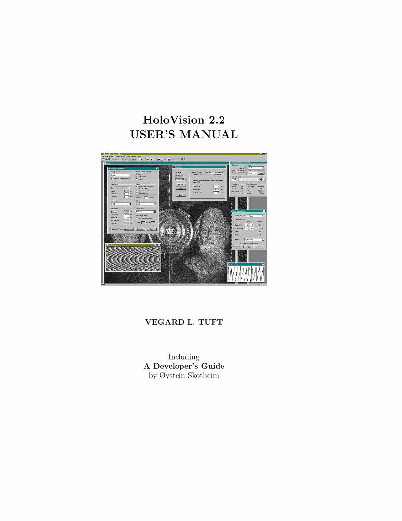
HoloVision 2.2
USER’S MANUAL
VEGARD L. TUFT
IncludingA Developer’s Guide
by Øystein Skotheim

HoloVision 2.2 User’sManual
1st Edition
June 25, 2001
Covers version 2.2.1
Vegard L. Tuft
Group of Technical Optics,Norwegian University of Science and Technology
Author’s email address: [email protected] web site: www.edge.no/projects/holovision/

HoloVision - WhereHolography Goes Digital
What HoloVision Does
HoloVision is an advanced, scientific application for digital holography. Holo-Vision can capture holograms with the aid of a digital camera or importholograms in the form of JPG, BMP, GIF and TIF files. Two reconstruc-tion methods - the Fresnel and convolution method - form the basis of theapplication and simulate wavefield propagation. Different filters and imageprocessing capabilities make the software a useful tool in any kind of opticalmeasuring technique that utilizes digital holography.HoloVision can also export files to WYKO Vision32 datasets and commu-nicate with Matlab via Active X.
HoloVision 2.2 is an open source program available for free under a GNUGeneral Public License as stated in App. D. It is released without warrantyof any kind. Source code is available upon request.
The Making of HoloVision
In 1999 Øystein Skotheim and the author needed software for acquisition ofholograms and numerical reconstruction of wavefronts. The obvious choicewas to write our own software, and the result was a Windows based appli-cation, HoloVision 1.0, released1 in June the following year.
As this version had limited capabilities, Øystein dedicated plenty of timeand a large part of his diploma thesis to the development of the 2.1 version.The major upgrades included
1This first version of HoloVision never had an official release, but is described in Ref.[1]
i
ii
• changing the FFT library for faster Fourier transform computations
• implementation of different reconstruction methods with several imageenhancing capabilities
• JPG, BMP, GIF and TIF support in order to collect holograms fromother sources than our Hamamatsu digital CCD camera
A description of HoloVision 2.1 can be found in his report on digital holog-raphy (Ref. [2]).
As of today HoloVision has reached its 2.2 version. It contains features thathave been useful to us, but of course, there is always room for improvement.Major updates in HoloVision 2.2 are
• WYKO Vision32 dataset export option
• Modified numerical lens, convolution algorithm and Fresnel algorithm
• Two zero mask filters (low- and highpass)
• Calculator for setup and reconstruction parameters
These updates are briefly described in Ref. [3].
Bug Report
We are happy to get reports on bugs in our software. Please explain what youdid prior to the occurrence and include the error messages that appeared, ifany.
Contact Information
If you want to aid us in the development of HoloVision, if you want to letus know about bugs, or if you just want to send us any comments: do nothesitate to contact us. As of June 25, 2001, our email addresses are:
• Vegard L. Tuft:
• Øystein Skotheim:

iii
You can find up-to-date information about HoloVision, including the latestversion of the software, here:
www.edge.no/projects/holovision/

Contents
1 Getting Started 1
1.1 Computer System Requirements . . . . . . . . . . . . . . . . 1
1.2 Obtaining and Installing HoloVision . . . . . . . . . . . . . . 1
1.2.1 Installing HoloVision From the CD-ROM . . . . . . . 2
1.2.2 Installing HoloVision From a Zip File . . . . . . . . . 2
1.3 Installing ITEX and Connecting the Camera (optional) . . . 2
1.4 Installing Matlab (optional) . . . . . . . . . . . . . . . . . . . 3
1.5 The HoloVision Environment . . . . . . . . . . . . . . . . . . 4
1.5.1 The Menu . . . . . . . . . . . . . . . . . . . . . . . . . 4
1.5.2 The Toolbar . . . . . . . . . . . . . . . . . . . . . . . 5
1.5.3 The HoloVision Matrix and the Matrix Window . . . 7
1.5.4 The HoloVision Workspace . . . . . . . . . . . . . . . 7
2 Handling Files and Images 8
2.1 Opening and Saving Files . . . . . . . . . . . . . . . . . . . . 8
2.1.1 Opening HVM Files . . . . . . . . . . . . . . . . . . . 8
2.1.2 Saving HVM Files . . . . . . . . . . . . . . . . . . . . 8
2.1.3 Working with Workspaces . . . . . . . . . . . . . . . . 9
2.1.4 Importing JPG, BMP, GIF and TIF Images . . . . . . 10
2.1.5 Exporting to JPG, BMP, GIF or TIF Format . . . . . 11
2.1.6 Saving as WYKO Vision32 Dataset . . . . . . . . . . 11
2.2 Matrix and File Information . . . . . . . . . . . . . . . . . . . 12
v
vi CONTENTS
2.2.1 Image Information . . . . . . . . . . . . . . . . . . . . 12
2.2.2 The Cross Section Window and Line Tool . . . . . . . 14
2.2.3 File Comments . . . . . . . . . . . . . . . . . . . . . . 14
2.3 Image Manipulation and Processing . . . . . . . . . . . . . . 15
2.3.1 The Edit Menu . . . . . . . . . . . . . . . . . . . . . . 15
2.3.2 The Select and Crop Tools . . . . . . . . . . . . . . . 15
2.3.3 Functions From the Image Menu . . . . . . . . . . . . 15
2.4 Printing HVM Files . . . . . . . . . . . . . . . . . . . . . . . 16
3 Camera Communication (optional) 18
3.1 Grabbing Images . . . . . . . . . . . . . . . . . . . . . . . . . 18
3.2 Camera Setup . . . . . . . . . . . . . . . . . . . . . . . . . . . 19
3.3 Camera Terminal Communication . . . . . . . . . . . . . . . 20
4 The Calculator 21
4.1 How to Use the Calculator . . . . . . . . . . . . . . . . . . . . 21
4.2 Parameters to Calculate . . . . . . . . . . . . . . . . . . . . . 22
5 Reconstructions and Calculations 23
5.1 The Reconstruct Wavefield Dialog Box . . . . . . . . . . . . . 23
5.1.1 How to Use the Numerical Lens With the ConvolutionMethod . . . . . . . . . . . . . . . . . . . . . . . . . . 27
5.2 The Calculations Dialog Box . . . . . . . . . . . . . . . . . . 28
5.3 Zero Mask Filters . . . . . . . . . . . . . . . . . . . . . . . . . 29
5.3.1 Quick Filtering . . . . . . . . . . . . . . . . . . . . . . 29
5.3.2 How to Use the Zero Mask Dialog Box . . . . . . . . . 29
5.4 Phase Unwrapping Algorithms . . . . . . . . . . . . . . . . . 31
5.5 Other Calculations . . . . . . . . . . . . . . . . . . . . . . . . 32
6 Communicating with Matlab (optional) 33
6.1 The Matlab Engine . . . . . . . . . . . . . . . . . . . . . . . . 33
CONTENTS vii
6.2 Starting the Engine and Sending Arrays to Matlab . . . . . . 33
6.3 Stopping the Engine . . . . . . . . . . . . . . . . . . . . . . . 34
7 Example 35
7.1 The Setup . . . . . . . . . . . . . . . . . . . . . . . . . . . . . 37
7.2 The Recordings . . . . . . . . . . . . . . . . . . . . . . . . . . 39
7.3 The Reconstructions . . . . . . . . . . . . . . . . . . . . . . . 40
8 A Developer’s Guide - by Øystein Skotheim 44
8.1 Obtaining and Installing HoloVision . . . . . . . . . . . . . . 44
8.1.1 Requirements . . . . . . . . . . . . . . . . . . . . . . . 45
8.1.2 Installation . . . . . . . . . . . . . . . . . . . . . . . . 46
A Troubleshooting 50
A.1 General . . . . . . . . . . . . . . . . . . . . . . . . . . . . . . 50
A.2 Camera Communication . . . . . . . . . . . . . . . . . . . . . 51
A.3 Matlab . . . . . . . . . . . . . . . . . . . . . . . . . . . . . . . 52
B Mathematical Reference 53
B.1 List of Symbols . . . . . . . . . . . . . . . . . . . . . . . . . . 53
B.2 The HoloVison Matrix . . . . . . . . . . . . . . . . . . . . . . 54
B.3 Show Values . . . . . . . . . . . . . . . . . . . . . . . . . . . . 54
B.4 The Calculator . . . . . . . . . . . . . . . . . . . . . . . . . . 54
B.5 Fourier Transforms . . . . . . . . . . . . . . . . . . . . . . . . 55
B.6 Reconstruction Methods . . . . . . . . . . . . . . . . . . . . . 56
B.7 Reference Wave Types . . . . . . . . . . . . . . . . . . . . . . 56
B.8 Tilt . . . . . . . . . . . . . . . . . . . . . . . . . . . . . . . . 56
B.9 Filters . . . . . . . . . . . . . . . . . . . . . . . . . . . . . . . 57
B.10 Numerical Lens . . . . . . . . . . . . . . . . . . . . . . . . . . 57
B.11 Calculations . . . . . . . . . . . . . . . . . . . . . . . . . . . . 57
viii CONTENTS
C Shortcut Keys 59
D The GNU General Public Licence 60
E CD-ROM Contents 67
E.1 Holovision 2.2.1 Win32 Install Binary . . . . . . . . . . . . . 67
E.2 Documentation . . . . . . . . . . . . . . . . . . . . . . . . . . 67
E.3 Holograms . . . . . . . . . . . . . . . . . . . . . . . . . . . . . 68
E.4 Setup Images . . . . . . . . . . . . . . . . . . . . . . . . . . . 68
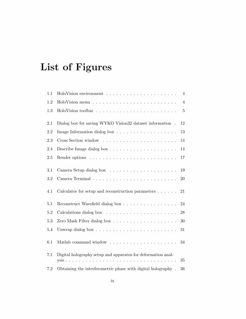
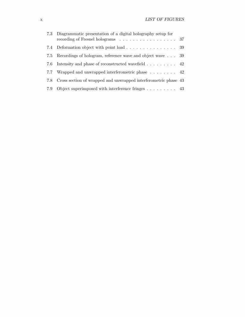
List of Figures
1.1 HoloVision environment . . . . . . . . . . . . . . . . . . . . . 4
1.2 HoloVision menu . . . . . . . . . . . . . . . . . . . . . . . . . 4
1.3 HoloVision toolbar . . . . . . . . . . . . . . . . . . . . . . . . 5
2.1 Dialog box for saving WYKO Vision32 dataset information . 12
2.2 Image Information dialog box . . . . . . . . . . . . . . . . . . 13
2.3 Cross Section window . . . . . . . . . . . . . . . . . . . . . . 14
2.4 Describe Image dialog box . . . . . . . . . . . . . . . . . . . . 14
2.5 Render options . . . . . . . . . . . . . . . . . . . . . . . . . . 17
3.1 Camera Setup dialog box . . . . . . . . . . . . . . . . . . . . 19
3.2 Camera Terminal . . . . . . . . . . . . . . . . . . . . . . . . . 20
4.1 Calculator for setup and reconstruction parameters . . . . . . 21
5.1 Reconstruct Wavefield dialog box . . . . . . . . . . . . . . . . 24
5.2 Calculations dialog box . . . . . . . . . . . . . . . . . . . . . 28
5.3 Zero Mask Filter dialog box . . . . . . . . . . . . . . . . . . . 30
5.4 Unwrap dialog box . . . . . . . . . . . . . . . . . . . . . . . . 31
6.1 Matlab command window . . . . . . . . . . . . . . . . . . . . 34
7.1 Digital holography setup and apparatus for deformation anal-ysis . . . . . . . . . . . . . . . . . . . . . . . . . . . . . . . . . 35
7.2 Obtaining the interferometric phase with digital holography . 36
ix
x LIST OF FIGURES
7.3 Diagrammatic presentation of a digital holography setup forrecording of Fresnel holograms . . . . . . . . . . . . . . . . . 37
7.4 Deformation object with point load . . . . . . . . . . . . . . . 39
7.5 Recordings of hologram, reference wave and object wave . . . 39
7.6 Intensity and phase of reconstructed wavefield . . . . . . . . . 42
7.7 Wrapped and unwrapped interferometric phase . . . . . . . . 42
7.8 Cross section of wrapped and unwrapped interferometric phase 43
7.9 Object superimposed with interference fringes . . . . . . . . . 43
Chapter 1
Getting Started
1.1 Computer System Requirements
• MS Windows 95 OS or higher (tested with 95, 98, NT 4.0 and 2000)
• 133 MHz Pentium CPU or equivalent (500 MHz Pentium III CPU orhigher recommended)
• 32 MB RAM (256 MB or more recommended)
• Less than 10 MB of hard disk space (excluding Matlab and ITEXsoftware)
In addition, the following soft- and hardware is required if you want to usethe camera and grabbing facilities:
• ITEX (ITEX SDK 3.3.1 was used in the development of HoloVision)
• IC-PCI framegrabber
• Hamamatsu C4745-95 digital CCD camera with camera controller
1.2 Obtaining and Installing HoloVision
You can install HoloVision 2.2.1 from the accompanying CD-ROM or down-load the latest zip file from the HoloVision web site at
www.edge.no/projects/holovision/
1
2 CHAPTER 1. GETTING STARTED
1.2.1 Installing HoloVision From the CD-ROM
1. Insert the CD into the CD drive of your computer.
2. The setup program should start automatically. If not, run the setup.exefile in the main directory of the CD-ROM.
3. Follow the instructions on the screen. You can choose between threeversions:
Light version All functionality included except Active X communi-cation with Matlab and ITEX support for camera communica-tion.
Matlab release All functionality included except ITEX support forcamera communication.
Full version Contains all functionality, including Active X commu-nication with Matlab and ITEX support for camera communi-cation. This version is only of interest if you have a HamamtsuC4742-95 digital CCD camera and an IC-PCI framegrabber.
• Note!During the installation process the setup program may say it is in-stalling the full version although the Light or Matlab release was cho-sen. The chosen version will be installed.
1.2.2 Installing HoloVision From a Zip File
1. Download the zip file to your hard disk.
2. Unzip it into a temporary folder. If the Use folder names check boxin WinZip is checked, WinZip will create a folder for you.
3. Run the setup.exe file.
4. Follow step 3 in Sec. 1.2.1.
5. Delete the temporary folder and its contents if desired.
1.3 Installing ITEX and Connecting the Camera(optional)
ITEX is necessary if you want to use the camera and grabbing facilitiesof HoloVision. However, since ITEX is copyright of Coreco Imaging and
1.4. INSTALLING MATLAB (OPTIONAL) 3
requires a license, this software is not included on the accompanying CD-ROM. Visit the Coreco Imaging website at
www.imaging.com
for more information. The Group of Technical Optics has its own licenseof ITEX SDK1 3.3.1 intended for in-house development of software, likeHoloVision. The rest of this section is aimed at people at this group.
1. Insert the ITEX CD into the CD drive of your computer.
2. Run the setup.exe file and follow the instructions.
3. See the Hamamatsu C4742-95 instruction manual (Ref. [6]) on how toconnect the camera.
1.4 Installing Matlab (optional)
You may omit this section if you only need the Light version.
You can install Matlab before or after the installation of HoloVision. Matlabis copyright of The MathWorks, Inc and requires a license.
• Follow the instructions in your Matlab documentation on how to installMatlab the usual way; no extra steps are necessary.
• Make shure you have the Matlab release of HoloVision installed onyour computer. If not, remove the version you do have and/or installthe Matlab release.
• Note!Matlab versions older than 5.3 may not support Active X.
1System Development Kit
4 CHAPTER 1. GETTING STARTED
1.5 The HoloVision Environment
Dialog box
Infowindow
CrossSectionwindow
Menu bar
Toolbar
Dialog box
Matrix window
Dialog box
Matrix window
Image
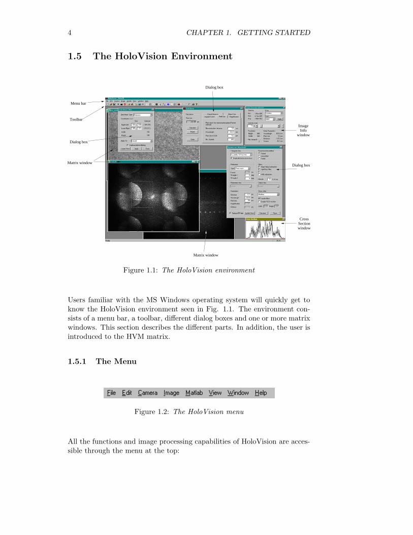
Figure 1.1: The HoloVision environment
Users familiar with the MS Windows operating system will quickly get toknow the HoloVision environment seen in Fig. 1.1. The environment con-sists of a menu bar, a toolbar, different dialog boxes and one or more matrixwindows. This section describes the different parts. In addition, the user isintroduced to the HVM matrix.
1.5.1 The Menu
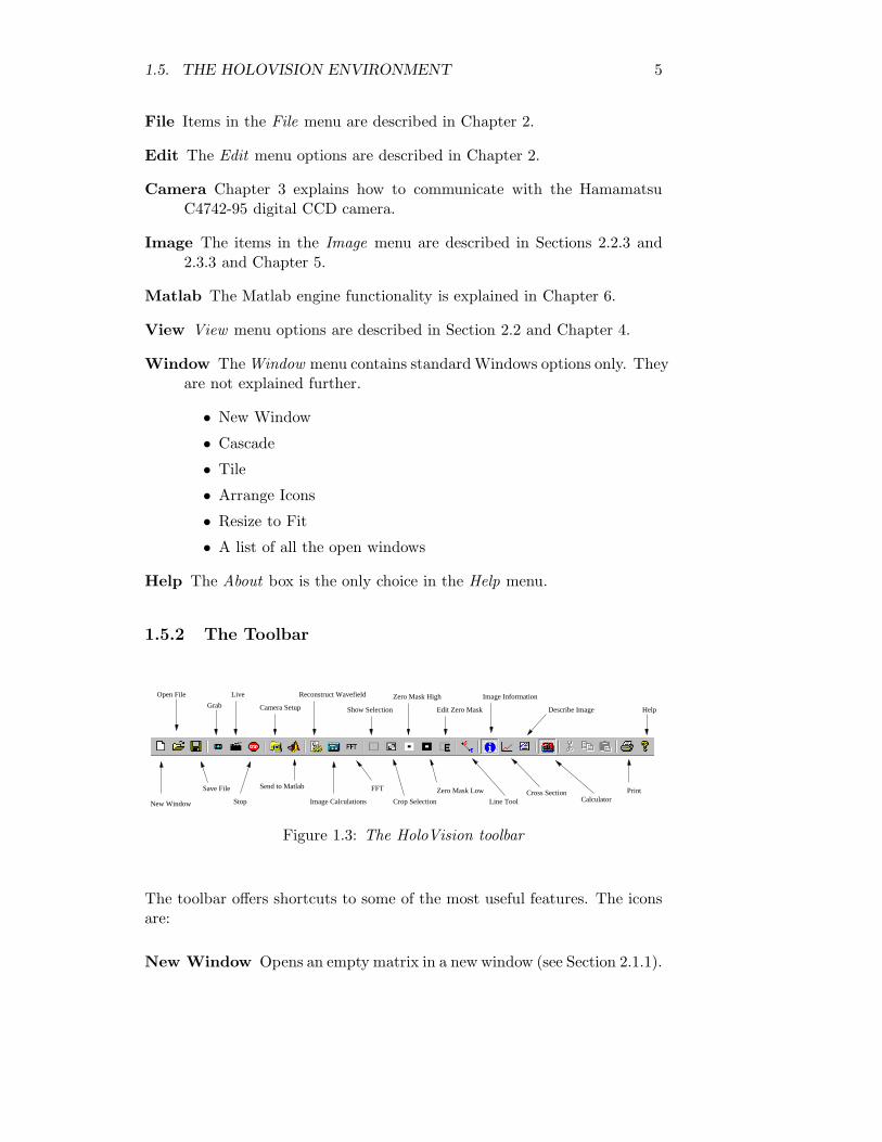
Figure 1.2: The HoloVision menu
All the functions and image processing capabilities of HoloVision are acces-sible through the menu at the top:
1.5. THE HOLOVISION ENVIRONMENT 5
File Items in the File menu are described in Chapter 2.
Edit The Edit menu options are described in Chapter 2.
Camera Chapter 3 explains how to communicate with the HamamatsuC4742-95 digital CCD camera.
Image The items in the Image menu are described in Sections 2.2.3 and2.3.3 and Chapter 5.
Matlab The Matlab engine functionality is explained in Chapter 6.
View View menu options are described in Section 2.2 and Chapter 4.
Window The Window menu contains standard Windows options only. Theyare not explained further.
• New Window
• Cascade
• Tile
• Arrange Icons
• Resize to Fit
• A list of all the open windows
Help The About box is the only choice in the Help menu.
1.5.2 The Toolbar
New Window Image Calculations
Send to Matlab
Help
PrintCalculator
Cross SectionLine Tool
Zero Mask Low
Crop Selection
FFT
Stop
Describe Image
Image Information
Edit Zero Mask
Zero Mask High
Show Selection
Reconstruct Wavefield
Camera Setup
Live
Grab
Open File
Save File
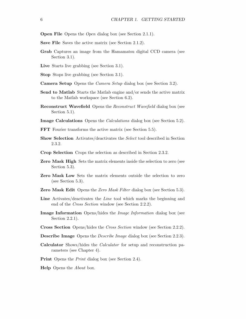
Figure 1.3: The HoloVision toolbar
The toolbar offers shortcuts to some of the most useful features. The iconsare:
New Window Opens an empty matrix in a new window (see Section 2.1.1).
6 CHAPTER 1. GETTING STARTED
Open File Opens the Open dialog box (see Section 2.1.1).
Save File Saves the active matrix (see Section 2.1.2).
Grab Captures an image from the Hamamatsu digital CCD camera (seeSection 3.1).
Live Starts live grabbing (see Section 3.1).
Stop Stops live grabbing (see Section 3.1).
Camera Setup Opens the Camera Setup dialog box (see Section 3.2).
Send to Matlab Starts the Matlab engine and/or sends the active matrixto the Matlab workspace (see Section 6.2).
Reconstruct Wavefield Opens the Reconstruct Wavefield dialog box (seeSection 5.1).
Image Calculations Opens the Calculations dialog box (see Section 5.2).
FFT Fourier transforms the active matrix (see Section 5.5).
Show Selection Activates/deactivates the Select tool described in Section2.3.2.
Crop Selection Crops the selection as described in Section 2.3.2.
Zero Mask High Sets the matrix elements inside the selection to zero (seeSection 5.3).
Zero Mask Low Sets the matrix elements outside the selection to zero(see Section 5.3).
Zero Mask Edit Opens the Zero Mask Filter dialog box (see Section 5.3).
Line Activates/deactivates the Line tool which marks the beginning andend of the Cross Section window (see Section 2.2.2).
Image Information Opens/hides the Image Information dialog box (seeSection 2.2.1).
Cross Section Opens/hides the Cross Section window (see Section 2.2.2).
Describe Image Opens the Describe Image dialog box (see Section 2.2.3).
Calculator Shows/hides the Calculator for setup and reconstruction pa-rameters (see Chapter 4).
Print Opens the Print dialog box (see Section 2.4).
Help Opens the About box.
1.5. THE HOLOVISION ENVIRONMENT 7
1.5.3 The HoloVision Matrix and the Matrix Window
HoloVision works on rectangular, two-dimensional arrays called HVM 2 ma-trices. Each element contains a complex value which can be written asz = a + bi, where the real part, a, and the imaginary part, b, are realnumbers.
HoloVision supports JPG, BMP, GIF and TIF images. The applicationconverts them to the HVM format when they are loaded - or exports HVMmatrices to any of the mentioned image types. How to do this is explainedin Sections 2.1.4 and 2.1.5.
The matrix window is a representation of an HVM matrix and displays itas an image on the screen. The user decides what part of the matrix he orshe wants to see (see Section 2.2.1).One or more matrix windows can be open at the same time.
1.5.4 The HoloVision Workspace
The HoloVision workspace is a collection of all the open HoloVision filesand the current setup parameters in the Reconstruct Wavefield dialog box.Only the windows that have been saved as HVM files are included in theworkspace.Section 2.1.3 explaines how to save and load workspaces.
2HVM means HoloVision Matrix, so the right term should be HV matrix
Chapter 2
Handling Files and Images
2.1 Opening and Saving Files
Opening and saving files is done as in most Windows-based software: fromthe File menu.
2.1.1 Opening HVM Files
• Choose File—New... from the menu or New Window from the toolbarif you want to create a new, empty HVM matrix. This is only necessaryif you want to grab images with the Hamamatsu camera (see Chapter3).
• Choose File—Open... or the Open File icon if you want to open anexisting HVM file. A dialog box in which you can specify one or morefiles will appear. Make sure the Files of type drop down list says“HoloVision Matrix (*.HVM)”.
2.1.2 Saving HVM Files
• Choose File—Save as... if you want to save the active HVM matrixunder a new name.
• Choose File—Save or the Save File icon if you want to save yourchanges to the active file.
• Note!The user is not asked to save the file when closing it. Any changesdone after it was changed the last time, will be lost.
8
2.1. OPENING AND SAVING FILES 9
Setup Parameters
In addition to the matrix data, each HVM file contains the values of foursetup parameters:
Source Distance Wavelength Pixel size
These are essential to the reconstruction process and are explained in Section5.1.
Change and save the setup parameters by following these steps:
1. Open the Reconstruct Wavefield dialog box by choosing Image—Reconstruct...from the menu or clicking the Reconstruct Wavefield icon on the tool-bar.
2. Edit the four parameter values. Source is only available if ReferenceType is “Spherical wave”.
3. Save the file.
File Comment
You can also comment each HVM file by following this procedure:
1. Open the Describe Image dialog box by choosing Image—Describe...from the menu or clicking the Describe Image icon on the toolbar.This dialog shows the comment associated with the active matrix.
2. Enter some text. The comment can be as long as your computersystem allows.
3. Click Save & Close to save the text and exit the dialog.
4. Save the file if you want the comment to stay with the file even afterit has been closed.
• Note!If you close the file without saving it, the comment will be erased.
2.1.3 Working with Workspaces
A workspace is a collection of the open HVM files and the current values ofthe four setup parameters
Source Distance Wavelength Pixel size
10 CHAPTER 2. HANDLING FILES AND IMAGES
Matrix windows that have not been saved yet, for instance recently importedJPG, BMP, GIF and TIF images, are not included.A workspace can be saved as an HWS file. It contains a list of all the HVMfiles in the workspace; the files themselves are not included. This meansthat any alterations done to one file in a workspace will affect all the otherworkspaces where this file is listed. In addition, if a HVM file is renamed ormoved, the file can not be opened when the workspace is loaded.The HWS file contains its own set of setup parameter values independent ofthe values associated with each HVM file.
Saving a Workspace
1. Open and/or save the HVM files you want to include in the workspace.
2. Open the Reconstruct Wavefield dialog box by choosing Image—Reconstruct...from the menu or clicking the Reconstruct Wavefield icon on the tool-bar.
3. Edit the setup parameter values. These are the values the dialog boxwill display when the workspace is loaded. They come in addition tothe values associated with each HVM file.
4. Save the workspace by choosing File—Save Workspace....
Loading a Workspace
1. Choose File—Load Workspace... from the menu and choose a file inthe dialog box that opens.
2. All the HVM files listed in the HWS file will open, and the setupparameter values are displayed in the Reconstruct Wavefield dialogbox.
2.1.4 Importing JPG, BMP, GIF and TIF Images
1. Choose File—Open... from the menu and a dialog box opens.
2. Specify the type of file you want to import in the Files of type dropdown list.
3. Choose one or more files to open. JPG, BMP, GIF and TIF images areautomatically converted to HVM matrices. The real part contains theoriginal image, while the imaginary part is set to zero. Color imagesbecome black-and-white by taking the average of the three colors red,green and blue.
2.1. OPENING AND SAVING FILES 11
2.1.5 Exporting to JPG, BMP, GIF or TIF Format
When exporting a HVM file to one of the JGP, BMP, GIF and TIF formats,the resulting file will contain the image as seen on the screen.
1. Specify what part of the HVM matrix to display and the intensityscale in the Image Information window.
2. Choose File—Export as... from the menu and a dialog box opens.
3. Specify the file format in the Files of type drop down list.
2.1.6 Saving as WYKO Vision32 Dataset
Unwrapped phase maps from HoloVision can serve as raw data for furtherprocessing and surface plots in the WYKO Vision32 software from VeecoInstruments. HoloVision exports HVM matrices to an ASCII file formatthat WYKO Vision32 can read.
1. Choose File—Export as... from the menu and a dialog box opens.
2. Choose “WYKO Vision Dataset (*.ASC)” from the Files of type dropdown list.
3. Enter a file name without any extension or with the extension “asc”or “ASC”.
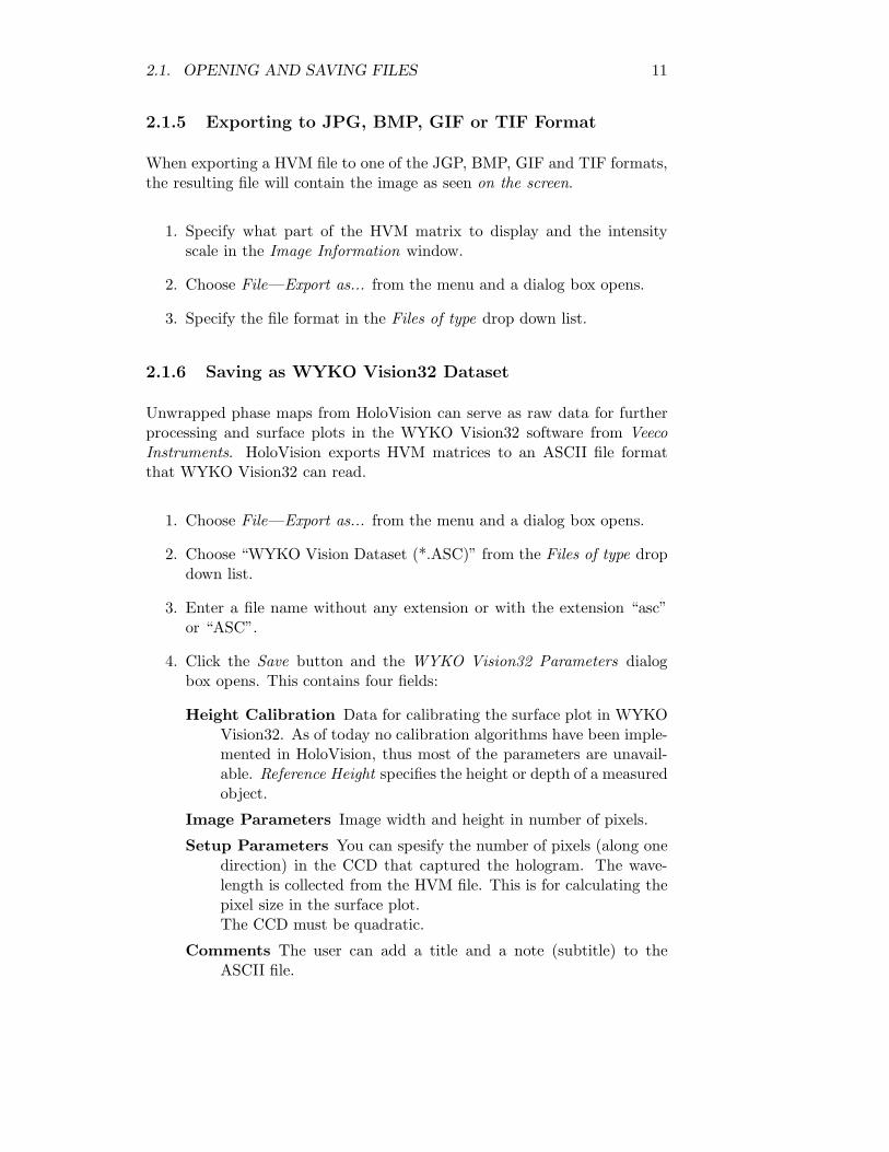
4. Click the Save button and the WYKO Vision32 Parameters dialogbox opens. This contains four fields:
Height Calibration Data for calibrating the surface plot in WYKOVision32. As of today no calibration algorithms have been imple-mented in HoloVision, thus most of the parameters are unavail-able. Reference Height specifies the height or depth of a measuredobject.
Image Parameters Image width and height in number of pixels.
Setup Parameters You can spesify the number of pixels (along onedirection) in the CCD that captured the hologram. The wave-length is collected from the HVM file. This is for calculating thepixel size in the surface plot.The CCD must be quadratic.
Comments The user can add a title and a note (subtitle) to theASCII file.
12 CHAPTER 2. HANDLING FILES AND IMAGES
Figure 2.1: Dialog box for saving WYKO Vision32 dataset information.
5. Click the Save File button.
• Note!Only the real part of the HVM matrix is copied to the WYKO Vision32dataset. This is the part occupied by the unwrapped phase.
2.2 Matrix and File Information
The Image Information and Cross Section windows provide useful informa-tion about the active matrix. Both are accessible through the View menuor the toolbar. You can also comment the HVM files, keeping importantnotes and image files together.
2.2.1 Image Information
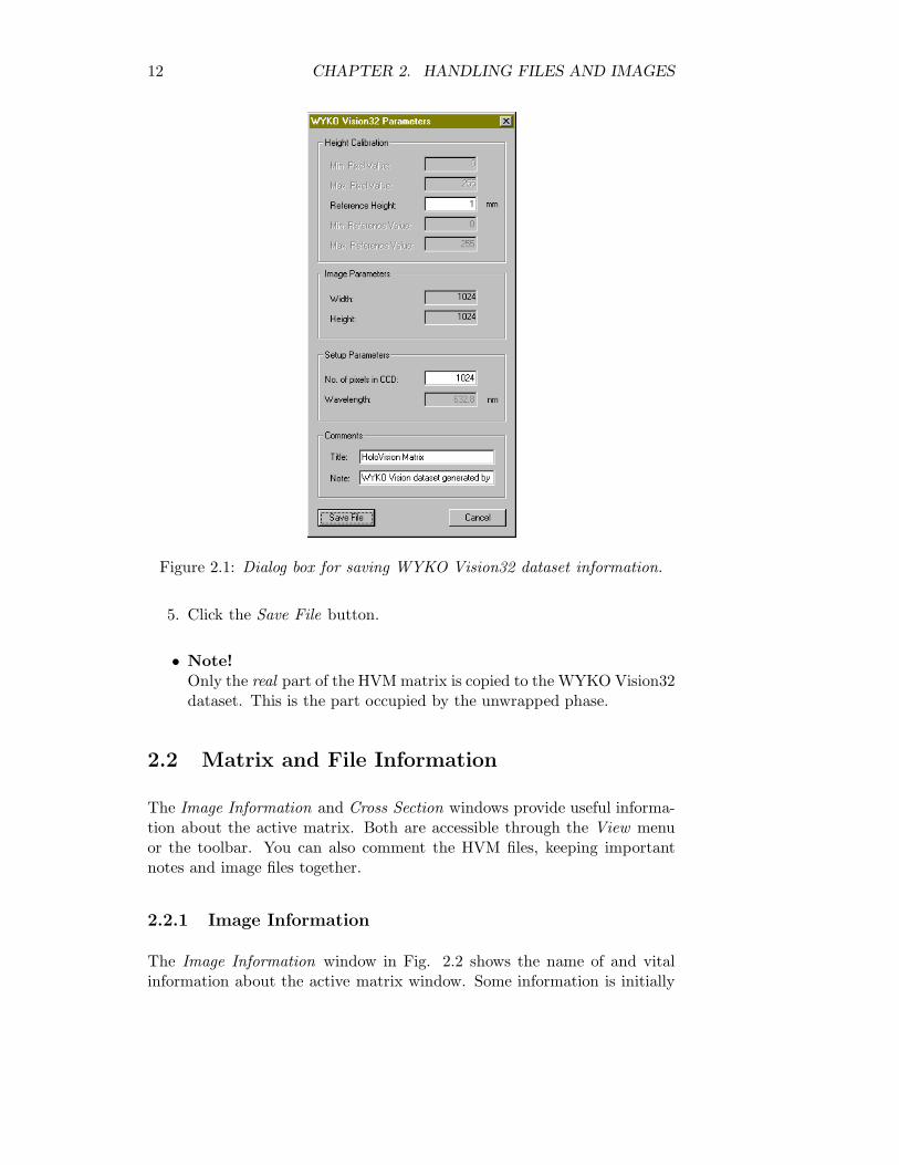
The Image Information window in Fig. 2.2 shows the name of and vitalinformation about the active matrix window. Some information is initially
2.2. MATRIX AND FILE INFORMATION 13
Figure 2.2: The Image Information dialog box in unexpanded (left) and ex-panded (right) state.
hidden, but by clikcing the button with an arrow, the unexpanded state ofthe dialog box alternates with the expanded state.
Show Decides which part of the matrix that is displayed on the screen.
• Real: a
• Imaginary: b
• Modulus:√
a2 + b2
• Phase: arctan(
ba
)modulo 2π
• Intensity: a2 + b2
• Log(Intensity): log10(a2 + b2)
Statistics The minimum, maximum and average pixel values.
Zoom Not implemented.
Intensity Scale Adjust the intensity in the image by using the slider orentering a value. This specifies the saturation point as a percentageof the maximum intensity. The matrix itself is not altered, only whatyou see on the screen.
Resolution Image width and height in number of pixels.
File Version Number Specifies what version of the HVM format the fileis, 1 or 2, where version 2 is the newer. If the value is 0, the file formatis unknown, like when you open a JPG, BMP, GIF or TIF file.
Setup Parameters The four setup parameters associated with the file.
14 CHAPTER 2. HANDLING FILES AND IMAGES
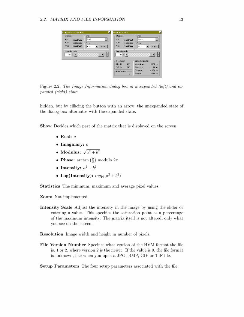
Figure 2.3: The Cross Section window.
2.2.2 The Cross Section Window and Line Tool
The Cross Section window shows the value of each pixel along a line in thematrix window. Default is the horizontal centerline. By clicking the Lineicon on the toolbar, a green marker becomes visible. You can now click anddrag anywhere in the matrix window and update the cross section. A redtick marks the beginning of the marker; a blue tick marks the end.Click the Line icon one more time to hide the green marker.
A red line indicates the average value in the Cross Section window.
2.2.3 File Comments
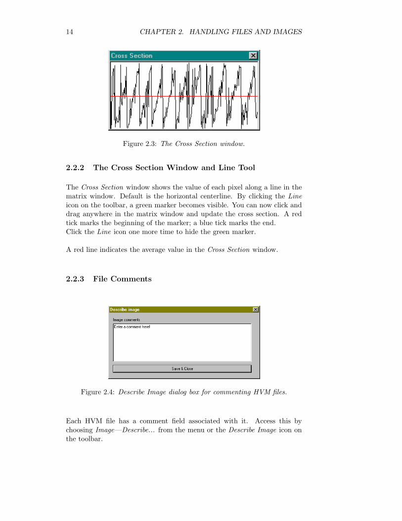
Figure 2.4: Describe Image dialog box for commenting HVM files.
Each HVM file has a comment field associated with it. Access this bychoosing Image—Describe... from the menu or the Describe Image icon onthe toolbar.
2.3. IMAGE MANIPULATION AND PROCESSING 15
2.3 Image Manipulation and Processing
Several image processing functions have been included in HoloVision. SeeChapter 5 for functions directly related to digital holography.
2.3.1 The Edit Menu
The standard Windows functions Undo, Cut, Copy and Paste are not im-plemented in version 2.2 of this software.
2.3.2 The Select and Crop Tools
1. A rectangular section of the matrix can be marked by choosing Edit—ShowSelection from the menu or the Show Selection icon on the toolbar.Click and drag to mark a section.
2. Click Edit—Crop Selection or the Crop Selection icon to paste theselection into a new window.
Regardless of what is shown in the window (the real part, modulus or anyother option mentioned in Section 2.2.1), HoloVision copies the real partof the active matrix into the real part of the new matrix and copies theimaginary part of the active matrix into the imaginary part of the new.
2.3.3 Functions From the Image Menu
Duplicate Copies the active matrix into a new window.
Square Root Performs a square root operation on each pixel in the matrix,but keeps the sign intact. If a+bi, where a is the real part and b is theimaginary part, is the original pixel value, sign(a)�
√|a|+sign(b)�√|b|i
is the new value.
Invert Inverts the real part of the matrix.
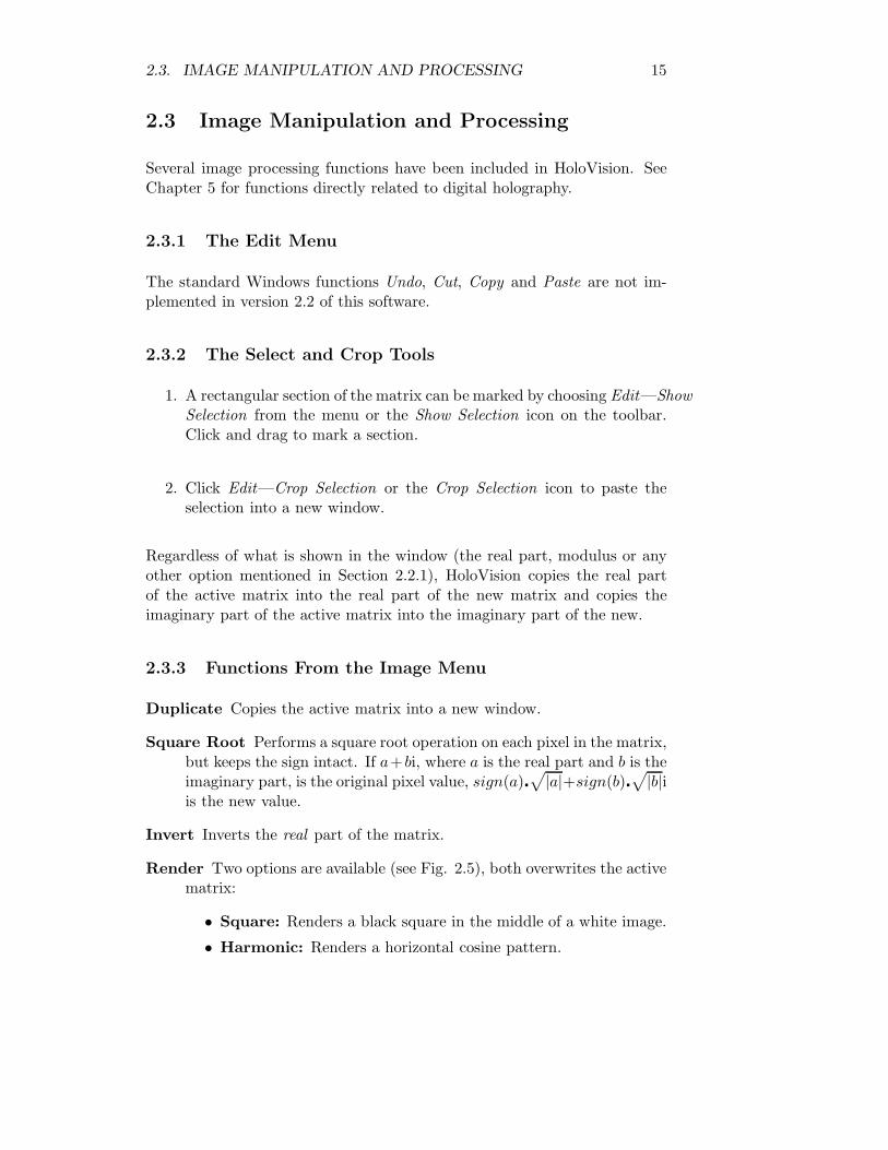
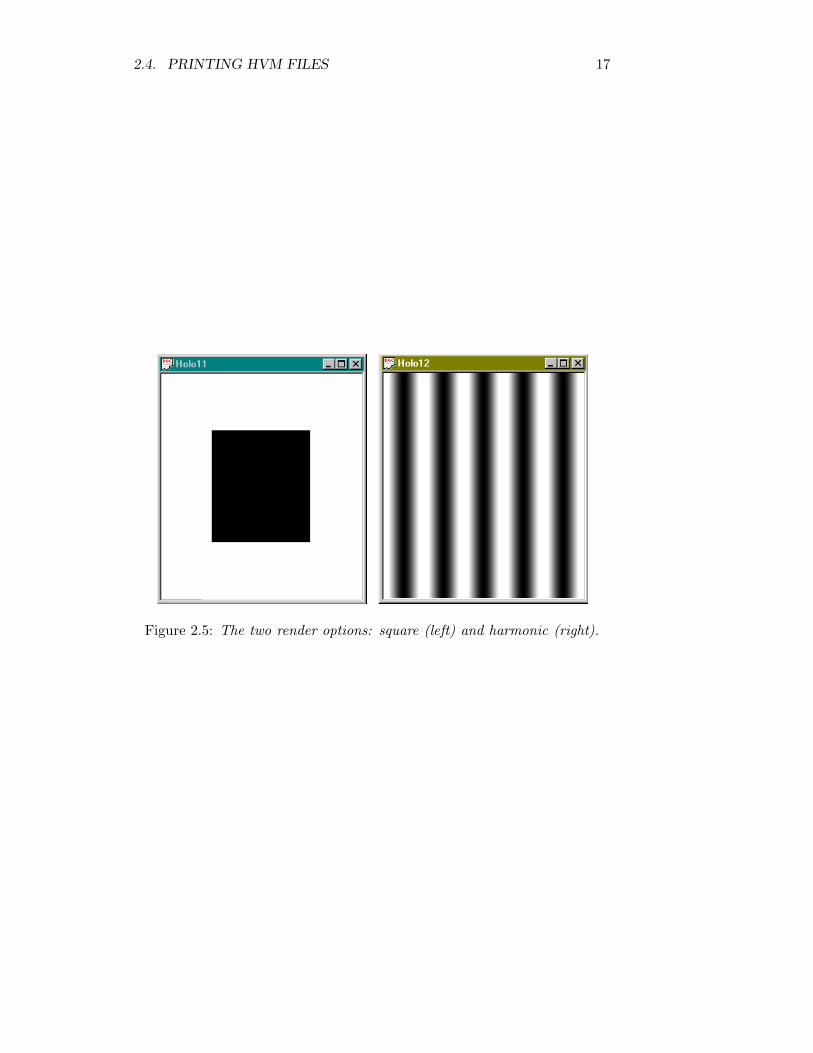
Render Two options are available (see Fig. 2.5), both overwrites the activematrix:
• Square: Renders a black square in the middle of a white image.
• Harmonic: Renders a horizontal cosine pattern.
16 CHAPTER 2. HANDLING FILES AND IMAGES
2.4 Printing HVM Files
Other printing facilities than the default have not been implemented. TheFile menu contain three choices:
Print... Opens the standard Print dialog box.
Print Preview Opens the standard Print Preview window. This does notshow the correct relation between image and page size.
Print Setup... Opens the standard Print Setup dialog box.
2.4. PRINTING HVM FILES 17
Figure 2.5: The two render options: square (left) and harmonic (right).
Chapter 3
Camera Communication(optional)
HoloVision was especially developed for communicating with a HamamatsuC4742-95 digital CCD camera through an IC-PCI framegrabber. If you wantto communicate with the camera and grab images, certain requirements haveto be fulfilled:
• ITEX has to be installed (see Section 1.3)
• IC-PCI framegrabber board must be installed
• Make sure the Hamamatsu C4742-95 digital camera is connected andswitched on
• The full version of HoloVision has to be installed (see Section 1.2)
3.1 Grabbing Images
• Acquire still images by choosing Grab from the Camera menu. Youcan also click the Grab icon on the toolbar (see Fig. 1.3) or push theF5 key. At least one matrix window has to be open, and the image istransferred to the real part of the active matrix. The imaginary partis set to zero.
• Start live grabbing by choosing Live or clicking the Live icon.
• Stop live grabbing by clicking the Stop icon.
18
3.2. CAMERA SETUP 19
• Note!Combining the live grabbing function with full resolution mode (seeSection 3.2) results in very slow update of the matrix.
3.2 Camera Setup
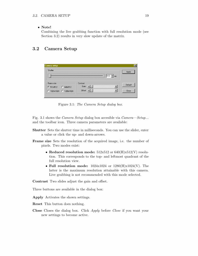
Figure 3.1: The Camera Setup dialog box.
Fig. 3.1 shows the Camera Setup dialog box accesible via Camera—Setup...and the toolbar icon. Three camera parameters are available:
Shutter Sets the shutter time in milliseconds. You can use the slider, entera value or click the up- and down-arrows.
Frame size Sets the resolution of the acquired image, i.e. the number ofpixels. Two modes exist:
• Reduced resolution mode: 512x512 or 640(H)x512(V) resolu-tion. This corresponds to the top- and leftmost quadrant of thefull resolution view.
• Full resolution mode: 1024x1024 or 1280(H)x1024(V). Thelatter is the maximum resolution attainable with this camera.Live grabbing is not recommended with this mode selected.
Contrast Two slides adjust the gain and offset.
Three buttons are available in the dialog box:
Apply Activates the shown settings.
Reset This button does nothing.
Close Closes the dialog box. Click Apply before Close if you want yournew settings to become active.
20 CHAPTER 3. CAMERA COMMUNICATION (OPTIONAL)
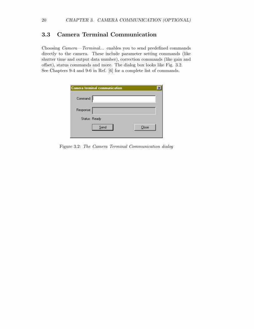
3.3 Camera Terminal Communication
Choosing Camera—Terminal... enables you to send predefined commandsdirectly to the camera. These include parameter setting commands (likeshutter time and output data number), correction commands (like gain andoffset), status commands and more. The dialog box looks like Fig. 3.2.See Chapters 9-4 and 9-6 in Ref. [6] for a complete list of commands.
Figure 3.2: The Camera Terminal Communication dialog
Chapter 4
The Calculator
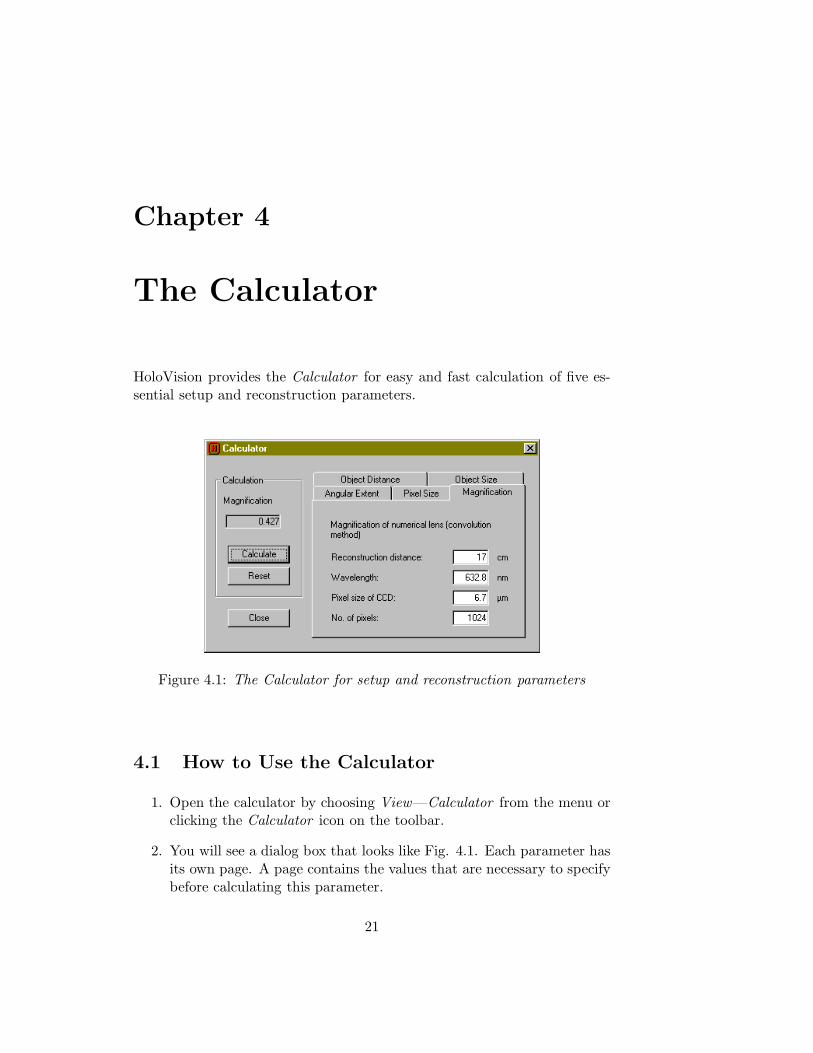
HoloVision provides the Calculator for easy and fast calculation of five es-sential setup and reconstruction parameters.
Figure 4.1: The Calculator for setup and reconstruction parameters
4.1 How to Use the Calculator
1. Open the calculator by choosing View—Calculator from the menu orclicking the Calculator icon on the toolbar.
2. You will see a dialog box that looks like Fig. 4.1. Each parameter hasits own page. A page contains the values that are necessary to specifybefore calculating this parameter.
21
22 CHAPTER 4. THE CALCULATOR
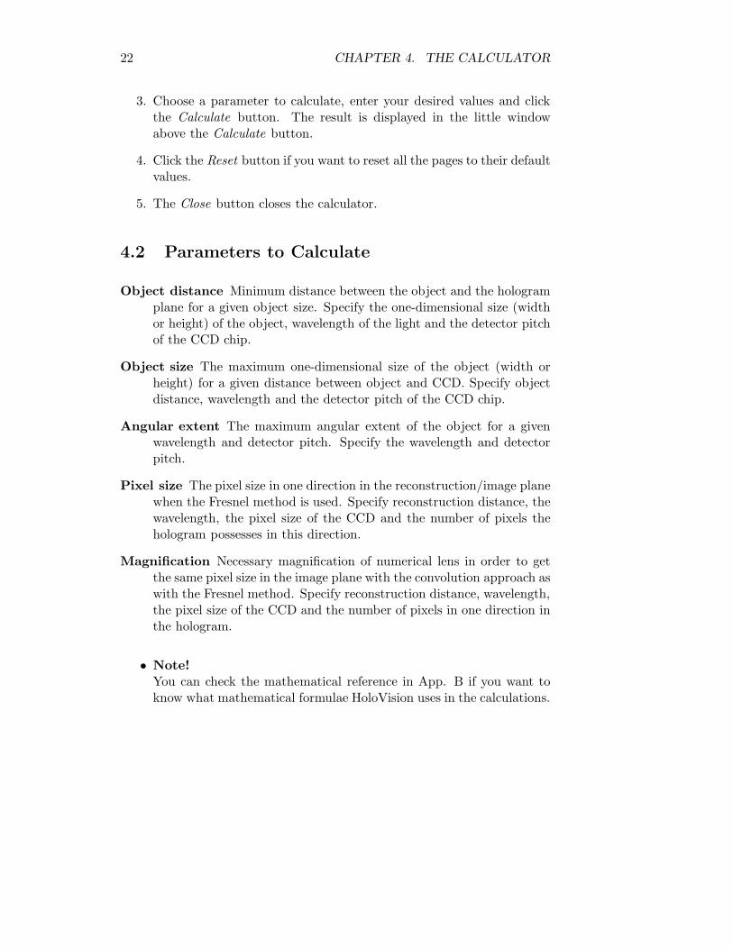
3. Choose a parameter to calculate, enter your desired values and clickthe Calculate button. The result is displayed in the little windowabove the Calculate button.
4. Click the Reset button if you want to reset all the pages to their defaultvalues.
5. The Close button closes the calculator.
4.2 Parameters to Calculate
Object distance Minimum distance between the object and the hologramplane for a given object size. Specify the one-dimensional size (widthor height) of the object, wavelength of the light and the detector pitchof the CCD chip.
Object size The maximum one-dimensional size of the object (width orheight) for a given distance between object and CCD. Specify objectdistance, wavelength and the detector pitch of the CCD chip.
Angular extent The maximum angular extent of the object for a givenwavelength and detector pitch. Specify the wavelength and detectorpitch.
Pixel size The pixel size in one direction in the reconstruction/image planewhen the Fresnel method is used. Specify reconstruction distance, thewavelength, the pixel size of the CCD and the number of pixels thehologram possesses in this direction.
Magnification Necessary magnification of numerical lens in order to getthe same pixel size in the image plane with the convolution approach aswith the Fresnel method. Specify reconstruction distance, wavelength,the pixel size of the CCD and the number of pixels in one direction inthe hologram.
• Note!You can check the mathematical reference in App. B if you want toknow what mathematical formulae HoloVision uses in the calculations.
Chapter 5
Reconstructions andCalculations
The main purpose of HoloVision is to calculate, i.e. reconstruct, the opticalwavefront, both amplitude and phase, in a given reconstruction or imageplane. The basis for this computation is a digital hologram, either captureddirectly with the Hamamatsu digital CCD camera (Chapter 3) or importedfrom a JPG, BMP, GIF or TIF file (Section 2.1.4). Sample holograms areincluded on the CD-ROM.
The theory that form the basis of the reconstruction dialog in Fig. 5.1 isexplained by Øystein Skotheim and the author in Refs. [2] and [3], respec-tively.
This chapter describes the functions related to digital holography, whileChapter 2 speaks of more general image processing functions.
5.1 The Reconstruct Wavefield Dialog Box
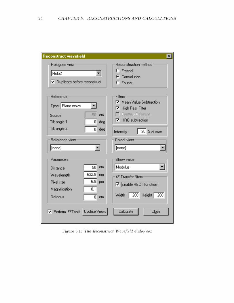
One dialog box presents all the available reconstruction methods, their op-tions and the parameters that need to be set before calculating the wave-front. The dialog opens by clicking Image—Reconstruct... from the menuor the Reconstuct Wavefield icon on the toolbar.
Hologram view Here you specify which of the open matrices you want toform the basis of your calculation. If Duplicate before reconstruct ischecked, HoloVision will open an empty matrix and place the resulthere.
Reconstruction Method Choose between these three reconstruction meth-
23
24 CHAPTER 5. RECONSTRUCTIONS AND CALCULATIONS
Figure 5.1: The Reconstruct Wavefield dialog box

5.1. THE RECONSTRUCT WAVEFIELD DIALOG BOX 25
ods:
• The Fresnel method
• The convolution method
• The Fourier method
Reference Specify the type of reference wave used in the making of thehologram:
• Plane wave
• Spherical wave: If this option is chosen, you can specify thedistance between the light source and the hologram plane in theSource text box. The sign of the distance follows the same con-ventions as used in Refs. [1], [2] and [3], i.e. a negative sign meansthe source was at the same side of the hologram as the object.
• Custom: If you have a recording of the reference wave (and thisis in an open window), you can use this in stead of the numericallycalculated reference. Choose this option and specify the correctmatrix in the Reference view section.
• Antiparallel wave: A plane wave with a negative sign.
In the reconstruction process the reference wave can be numericallytilted by an angle given by the Tilt angle 1 and Tilt angle 2 in thehorisontal and vertical direction, respectively. Use this function toplace the object in the middle of the reconstructed image, but notethat only small angles of 1-2◦ are necessary.
• Note!With the Fourier method the reference has to be a spherical wavewith its source positioned in the object plane. As a consequenceneither Type, Source nor Distance can be specified.
Filters HoloVision can improve the image quality and its signal to noiseratio in three ways.
• Mean Value Subtraction: The MVS function calculates themean value, which is subtracted from the hologram before recon-struction, thus creating a downshift in its intensity. The purposeis to suppress the so-called dc term which can be seen as a brightcentral square in the middle of the reconstructed wave field. Seefor example Ref. [2]. The best result is obtained with a planereference wave.
26 CHAPTER 5. RECONSTRUCTIONS AND CALCULATIONS
While negative intensity values are optically impossible, they areindeed numerically feasible and may result from this subtraction.
• High Pass Filter: A spatial highpass filter removes slowly vary-ing periodic noise while keeping important image information ofhigher spatial frequencies intact. This is a way to (partly) removethe disturbing “cloud” also seen in the middle of a reconstruction.
• Contrast Enhance: Not implemented.
• HRO Subtraction: This function requires three recordings: arecording of the object field alone, one of the reference field alone(to be specified in the Object View and Reference View, respec-tively), and one of the hologram. The reference and object wavesare then subtracted from the hologram, leaving the desired in-terference terms behind. The result is a reconstruction with thebright center and the surrounding noise at least partly removed.
Intensity Specifies the intensity scaling in the reconstructed image. Thevalue is the saturation point as a percentage of the maximum intensity.
Reference View Choose (among the open windows) which matrix youwant to use as a reference recording in the reconstruction. Availablewith the Custom option in the Reference section or when the HROSubtraction box is checked.
Object View Choose (among the open windows) which matrix you wantto use as an object recording in the reconstruction. Available whenthe HRO Subtraction box is checked.
Parameters Some of these parameters need to be set, depending on thereconstruction method and type of reference wave:
• Distance: This parameter has different meaning for the differentreconstruction methods.
– Fresnel: Distance from the hologram plane to the reconstruc-tion (image) plane. When the distance is a negative value,the reconstruction plane is on the same side of the hologramas the object.
– Convolution: Distance from object to hologram plane. SeeSection 5.1.1.
– Fourier: Not available with the Fourier method.
• Wavelength: The wavelength used when recording the holo-gram.
• Pixel size: The pixel size of the CCD chip. HoloVision assumesquadratic pixels.
5.1. THE RECONSTRUCT WAVEFIELD DIALOG BOX 27
• Magnification: Magnification of numerical lens (see Section5.1.1). Must be larger than 0 and less than 1. Enter 0 if youwant to omit the lens altogether. Available when “Convolution”is checked in the Reconstruction method section.
• Defocus: Shifts the image plane when using the convolutionmethod and the numerical lens (see Section 5.1.1).
Show Value Specifies what part of the reconstruction result that is dis-played on the screen. The alternatives are the same as in Section2.2.1.
4F Transfer Filter This is a numerical implementation of an optical 4fsystem with a spatial lowpass filter. Matrix elements outside a cen-tral rectangle of specified width and height are set to zero. Use thisfunction to, for instance, mask off the virtual image, see Ref. [2].
Perform IFFT shift When this option is checked the upper left quadrantof the reconstructed image is swapped with the lower right, and theupper right is swapped with the lower left.
The Update View button refreshes the list of open windows in the HologramView, Reference View and Object View sections, while the Calculate andClose buttons starts the reconstruction and closes the dialog box, respec-tively.
5.1.1 How to Use the Numerical Lens With the ConvolutionMethod
A numerical lens in the hologram plane is available when using the con-volution method. Based on the entered Distance and Magnification values,HoloVision will find a new image plane by using the well-known lens formula.
1. Choose “Convolution” in the Reconstruction method section.
2. In the Distance box specify the distance between the object and holo-gram. Entering a negative value will invoke a negative lens. A positivesign invokes a positive lens.
3. In the Magnification box enter a value for the desired magnification ofthe numerical lens.
• Use the calculator (Chapter 4) to find the correct magnification.
• The magnification must be larger than 0 and less than 1.
• Enter 0 if you want to omit the lens.
28 CHAPTER 5. RECONSTRUCTIONS AND CALCULATIONS
4. Enter a value in the Defocus box if you want to reconstruct the wave-front in a different plane than the automatically calculated one.
5.2 The Calculations Dialog Box
Figure 5.2: The Calculations dialog box
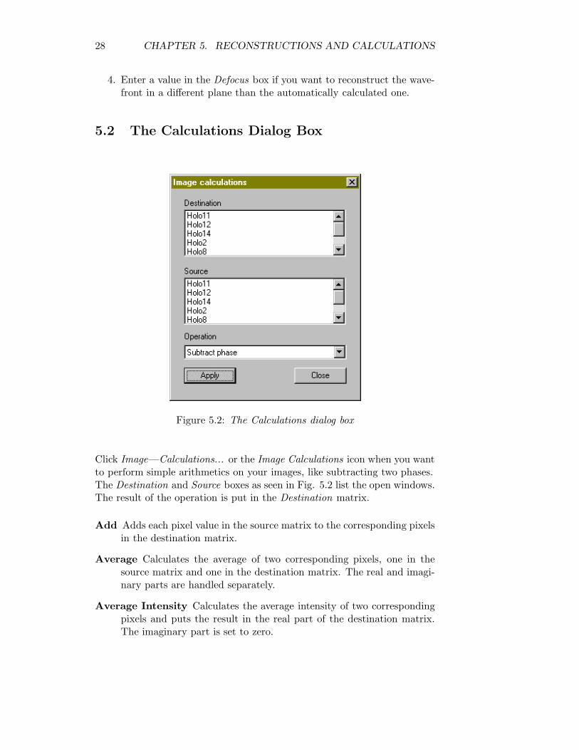
Click Image—Calculations... or the Image Calculations icon when you wantto perform simple arithmetics on your images, like subtracting two phases.The Destination and Source boxes as seen in Fig. 5.2 list the open windows.The result of the operation is put in the Destination matrix.
Add Adds each pixel value in the source matrix to the corresponding pixelsin the destination matrix.
Average Calculates the average of two corresponding pixels, one in thesource matrix and one in the destination matrix. The real and imagi-nary parts are handled separately.
Average Intensity Calculates the average intensity of two correspondingpixels and puts the result in the real part of the destination matrix.The imaginary part is set to zero.
5.3. ZERO MASK FILTERS 29
Subtract Subtracts each pixel value in the source matrix from the corre-sponding pixels in the destination matrix.
Subtract Phase Subtracts the phase of each pixel in the source matrixfrom the corresponding phase values in the destination matrix andputs the result in the real part of the destination. The imaginary partis set to zero.
Clicking the Apply button starts the calculation, while clicking the Closebutton closes the dialog box.
5.3 Zero Mask Filters
The zero mask filters in HoloVison multiplies your image with a RECTfunction, meaning the area inside or outside your rectangular selection is setto zero.
Highpass The real and imaginary parts inside the selection are set to zero.
Lowpass The real and imaginary parts outside the selection are set to zero.
5.3.1 Quick Filtering
1. Use the Select tool described in Section 2.3.2 to mark an area in theimage.
2. Click the Zero Mask High or Zero Mask Low button on the toolbar(the filters are also available from the menu: Image—Filter—ZeroMask).
5.3.2 How to Use the Zero Mask Dialog Box
Sometimes it is necessary to know the exact coordinates of the selection, forinstance when you want to make sure that the same area in two or moreimages are masked off.
1. Open the Zero Mask Filter dialog box by clicking the Edit Zero MaskSelection icon or choosing Image—Filter—Zero Mask—Edit... fromthe menu when a file is open.
30 CHAPTER 5. RECONSTRUCTIONS AND CALCULATIONS
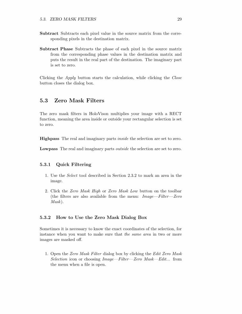
Figure 5.3: The Zero Mask Filter dialog box
2. The dialog box shows the coordinates of the selected area, if any, andthe name of the active matrix. These data will update automaticallywhen another matrix becomes the active window.The first coordinate is the horizontal, while the second is the vertical.(0,0) is the upper left corner of the window.
3. Choose one of the open files and select a new area with the Select tool.Click the Update Views button to see the coordinates of this selection.
4. If desired, modify the coordinates in the New coloumn.
5. Choose what type of filter you want to use in the Zero Mask Type dropdown list.
6. Choose the matrix you want to filter in the Apply to drop down list.The active matrix window is automatically suggested. This functionenables an easy way to mask off the exact same area in two or moreimages.
7. Check Duplicate before filtering if you want to keep the original image.
8. Click Apply to filter the matrix.
9. Click the Close button, click the Edit Zero Mask Selection or chooseImage—Filter—Zero Mask—Edit... to close the dialog box.
5.4. PHASE UNWRAPPING ALGORITHMS 31
• Note! The filter function uses the coordinates in the New coloumn.These may differ from the selected area.
5.4 Phase Unwrapping Algorithms
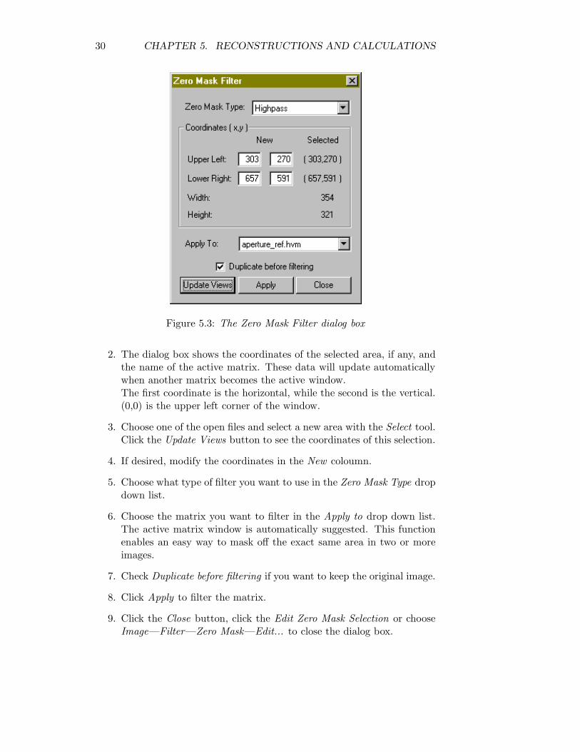
Figure 5.4: The Unwrap dialog box
HoloVision provides the user with six choices in the Unwrap Image dialogbox available from the Image—Unwrap... menu (see Fig. 5.4):
• Horizontal Unwrap
• Vertical Unwrap
• Goldstein’s Cut Line
• Least Squares Unwrap
• Quality Guided
• Mask Cut
32 CHAPTER 5. RECONSTRUCTIONS AND CALCULATIONS
Ref. [4] contains more information on the different unwrapping techniquesand a performance comparison.
In addition, the Unwrap Image dialog box gives access to lowpass and me-dian filters. These algorithms can consider as many as 15 by 15 pixels in asquare surrounding the evaluated pixel.
When an unwrapping is done, four options are available:
Undo last operation Returns the last image.
Back to original image Returns the matrix as it was before any unwrap-ping or filtering.
Exit and use this image Closes the dialog box.
Cancel and forget image Closes the dialog box and returns the matrixas it was originally.
5.5 Other Calculations
The Image menu also provides some simple image processing tools:
FFT Fourier transforms the matrix by using a two-dimensional Fast FourierTransform. This function is also available through the FFT icon onthe toolbar.
Inverse FFT Fourier transforms the matrix by using an inverse two-dimensionalFast Fourier Transform.
Shift The upper left quadrant of the image is swapped with the lower right,and the upper right is swapped with the lower left.
Filter Provides the same MVS and highpass filters found in Section 5.1 inaddition to four median filters from 3x3 to 9x9.
Chapter 6
Communicating with Matlab(optional)
6.1 The Matlab Engine
HoloVision uses AxtiveX to communicate with Matlab. This means thatHoloVision can start a separate Matlab process, send data to Matlab andend the same process. The process is called an engine.
HoloVision sends your active matrix as a complex array of double precisionto Matlab. You can then process your arrays further using the functionalitythat Matlab offers. If you are new to Matlab and want to learn more aboutthis language of technical computing, Ref. [7] is a good place to start.Click Matlab in the menu bar to access the Matlab menu in HoloVision. Ashortcut is available on the toolbar.
6.2 Starting the Engine and Sending Arrays toMatlab
1. Choose the matrix you want to send to Matlab.
2. The engine starts by clicking Send to Matlab. A new Matlab windowopens, and the matrix is transferred. This process will not affect otherMatlab processes opened manually by the user, either before or afterthe engine startup.
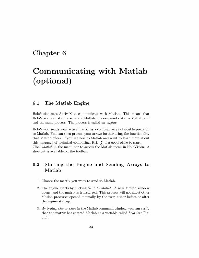
3. By typing who or whos in the Matlab command window, you can verifythat the matrix has entered Matlab as a variable called holo (see Fig.6.1).
33
34 CHAPTER 6. COMMUNICATING WITH MATLAB (OPTIONAL)
4. While the engine is open, you can send more matrices into the con-nected Matlab workspace by clicking Send to Matlab repeatedly. Notethat the old holo variable is overwritten when you transfer a new ma-trix and thus needs to be renamed if you want to keep it.
Figure 6.1: The Matlab command window after engine startup and typingwhos on the command line.
• Note!See the troubleshooting list in App. A if the engine won’t start
6.3 Stopping the Engine
• Clicking Stop Engine ends the process and closes the Matlab window.
• Exitting HoloVision also stops the engine. However, if Matlab doesn’tclose itself after a while you may have to close the Matlab windowmanually.
• Note!Note that closing the Matlab window manually (either by clicking theupper right corner or choosing File—Exit in Matlab) does not stopthe engine. An error messsage will then appear if you try to restartthe engine.
Chapter 7
Example
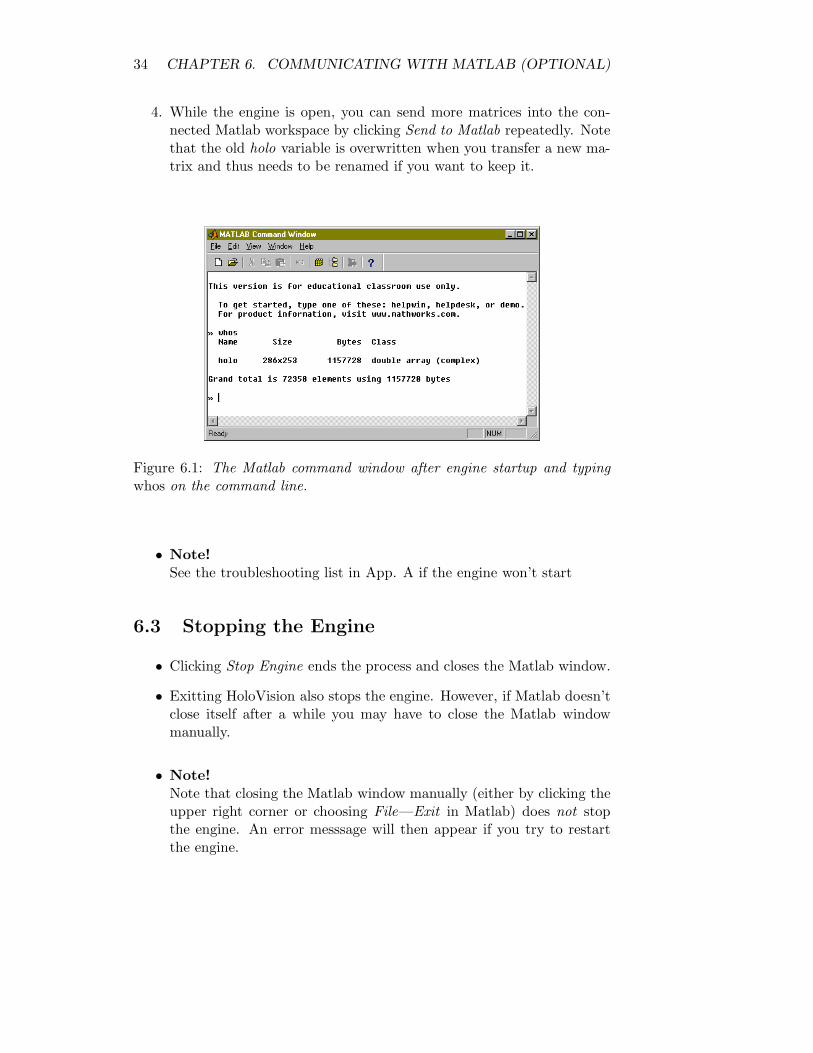
Figure 7.1: Digital holography setup and apparatus for deformation analysis.
This chapter is a short demonstration of a setup used during the develop-ment of HoloVision. The demonstration shows how the software and digitalholography can be used in optical interferometry. Two off-axis Fresnel holo-grams [5] of an object in two different states was recorded.The accompanying CD-ROM contains the recordings in this example.
The interested reader may consult Ref. [2] for a more detailed description
35
36 CHAPTER 7. EXAMPLE
of a similar setup, while Ref. [1] demonstrates the Fourier method. Contourgeneration with the two-angle method and digital holography is explainedin Ref. [3].
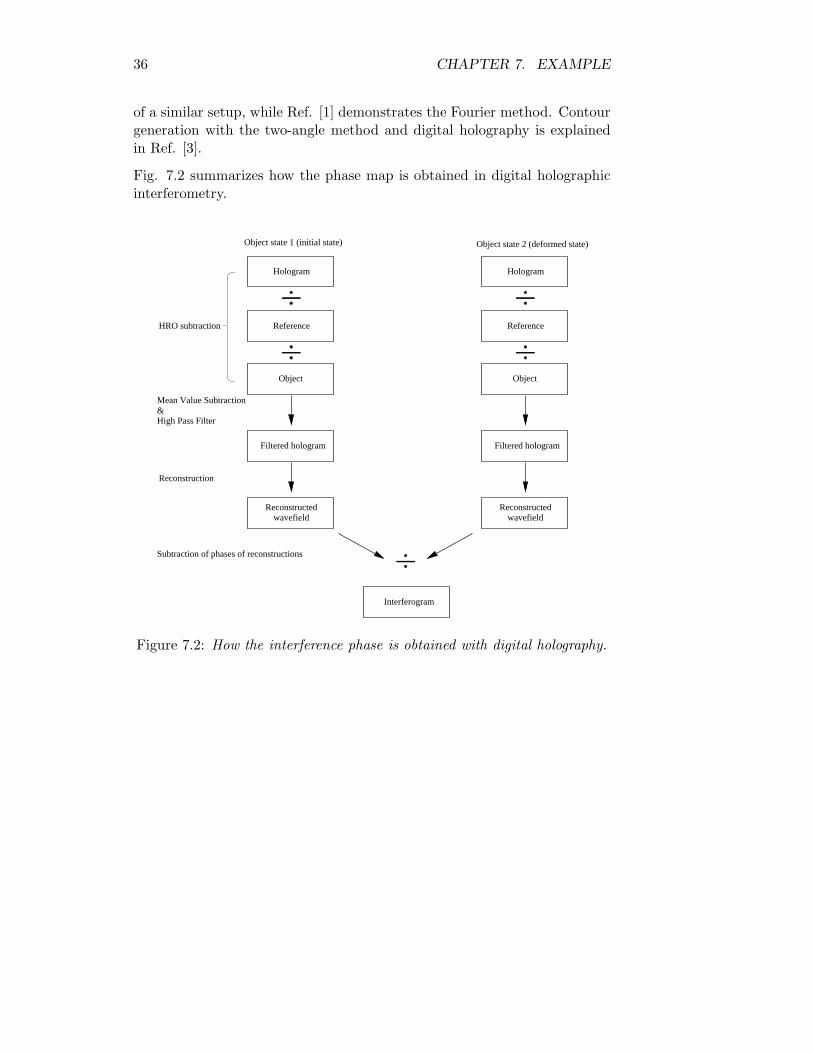
Fig. 7.2 summarizes how the phase map is obtained in digital holographicinterferometry.
Subtraction of phases of reconstructions
&High Pass Filter
Reconstructedwavefield
Reconstructedwavefield
Interferogram
HRO subtraction
Reconstruction
Object
Reference
Hologram
Filtered hologram
Object
Reference
Hologram
Filtered hologram
Object state 1 (initial state) Object state 2 (deformed state)
Mean Value Subtraction
Figure 7.2: How the interference phase is obtained with digital holography.
7.1. THE SETUP 37
7.1 The Setup
ML
LASER
CCD
S
S
AF
ML
SF
BS
CBS
OBJECT
d
D
CL
NL
M
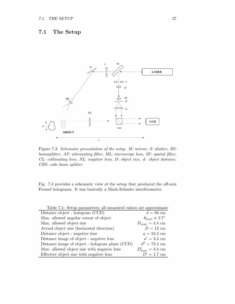
Figure 7.3: Schematic presentation of the setup. M: mirror, S: shutter, BS:beamsplitter, AF: attenuating filter, ML: microscope lens, SF: spatial filter,CL: collimating lens, NL: negative lens, D: object size, d: object distance,CBS: cube beam splitter.
Fig. 7.3 provides a schematic view of the setup that produced the off-axisFresnel holograms. It was basically a Mach-Zehnder interferometer.
Table 7.1: Setup parameters; all measured values are approximateDistance object - hologram (CCD) d = 94 cmMax. allowed angular extent of object θmax ≈ 2.7◦
Max. allowed object size Dmax = 4.4 cmActual object size (horizontal direction) D = 12 cmDistance object - negative lens a = 24.3 cmDistance image of object - negative lens a′ = 3.4 cmDistance image of object - hologram plane (CCD) d′′ = 72.4 cmMax. allowed object size with negative lens D′
max = 3.4 cmEffective object size with negative lens D′ = 1.7 cm
38 CHAPTER 7. EXAMPLE
The following is a list of equipment used for capturing and processing ofholograms:
Optical table: TMC with vibration absorbers.
Laser: Spectra Physics Model 124B, Helium-Neon, multimode, 15 mW.
Beamsplitters: 2 VBA-200, adjustable with circular gradient. One splitthe laser beam into an object and reference wave. The other reducedthe intensity of the reference.
Lenses: One 40/0.65 microscope lens and one negative lens with focallength -4.0 cm.
Mirrors: Three mirrors with high-sensitive adjustable tilting.
Object: Metal plate with adjustable point load.
Filter: Spectra Physics Spatial Filter 332 with collimator.
Shutters: One shutter in each path of the interferometer.
Recording device: Hamamatsu C4742-95 digital CCD camera (black andwhite) with serial interface for external camera control and with thelens removed.
Computer: PC with 500 MHz Pentium III processor, 512 MB RAM, Win-dows NT 4.0 OS, IC-PCI framegrabber device.
Software: HoloVision 2.2, ITEX SDK 3.3.1.
Miscellaneous: Magnetic supporters, optical mounts, posts, black card-board (for screening of parasitic reflections) etc.
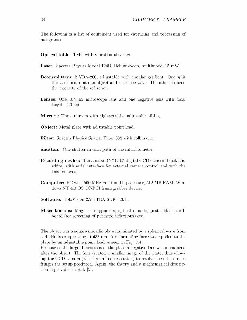
The object was a square metallic plate illuminated by a spherical wave froma He-Ne laser operating at 633 nm. A deformating force was applied to theplate by an adjustable point load as seen in Fig. 7.4.Because of the large dimensions of the plate a negative lens was introducedafter the object. The lens created a smaller image of the plate, thus allow-ing the CCD camera (with its limited resolution) to resolve the interferencefringes the setup produced. Again, the theory and a mathematical descrip-tion is provided in Ref. [2].
7.2. THE RECORDINGS 39
Figure 7.4: Deformation object with point load.
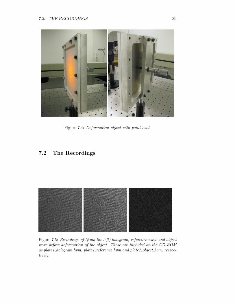
7.2 The Recordings
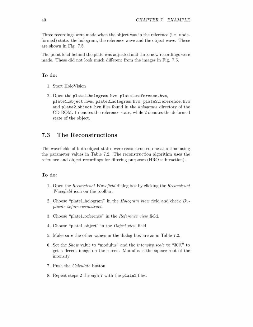
Figure 7.5: Recordings of (from the left) hologram, reference wave and objectwave before deformation of the object. These are included on the CD-ROMas plate1 hologram.hvm, plate1 reference.hvm and plate1 object.hvm, respec-tively.
40 CHAPTER 7. EXAMPLE
Three recordings were made when the object was in the reference (i.e. unde-formed) state: the hologram, the reference wave and the object wave. Theseare shown in Fig. 7.5.
The point load behind the plate was adjusted and three new recordings weremade. These did not look much different from the images in Fig. 7.5.
To do:
1. Start HoloVision
2. Open the plate1 hologram.hvm, plate1 reference.hvm,plate1 object.hvm, plate2 hologram.hvm, plate2 reference.hvmand plate2 object.hvm files found in the holograms directory of theCD-ROM. 1 denotes the reference state, while 2 denotes the deformedstate of the object.
7.3 The Reconstructions
The wavefields of both object states were reconstructed one at a time usingthe parameter values in Table 7.2. The reconstruction algorithm uses thereference and object recordings for filtering purposes (HRO subtraction).
To do:
1. Open the Reconstruct Wavefield dialog box by clicking the ReconstructWavefield icon on the toolbar.
2. Choose “plate1 hologram” in the Hologram view field and check Du-plicate before reconstruct.
3. Choose “plate1 reference” in the Reference view field.
4. Choose “plate1 object” in the Object view field.
5. Make sure the other values in the dialog box are as in Table 7.2.
6. Set the Show value to “modulus” and the intensity scale to “30%” toget a decent image on the screen. Modulus is the square root of theintensity.
7. Push the Calculate button.
8. Repeat steps 2 through 7 with the plate2 files.
7.3. THE RECONSTRUCTIONS 41
Table 7.2: Reconstruction parameters as used in the Reconstruct Wavefielddialog box
Reconstruction method FresnelReference wave type Plane waveReference source N/ATilt angle 1 0◦
Tilt angle 2 0◦
Mean Value Subtraction YesHigh Pass Filter YesContrast Enhance N/AHRO Subtraction YesDistance -72.4 cmWavelength 632.8 nmPixel size 6.7 µmMagnification N/ADefocus N/A4f Transfer Filter NoPerform IFFT Shift Yes
9. Close the dialog box.
10. Save the reconstructions as plate1 rec.hvm and plate2 rec.hvm.
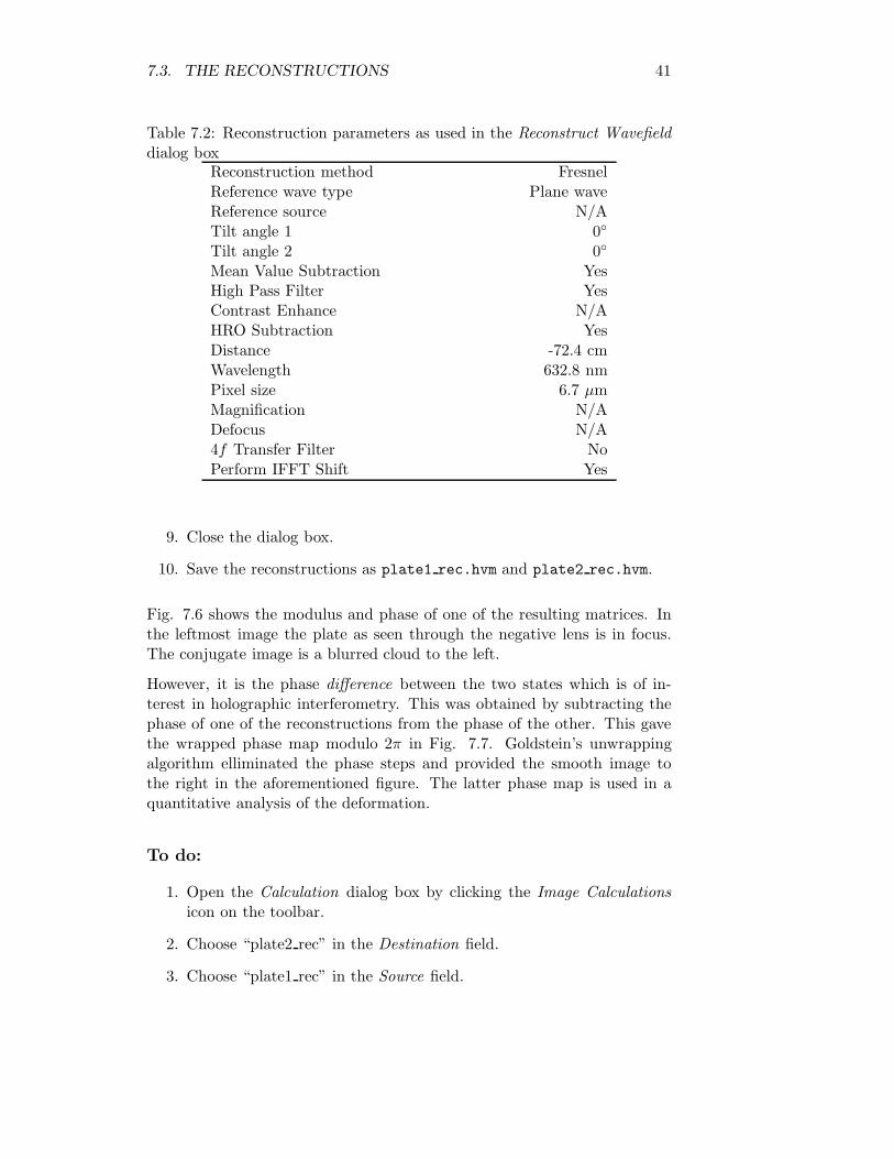
Fig. 7.6 shows the modulus and phase of one of the resulting matrices. Inthe leftmost image the plate as seen through the negative lens is in focus.The conjugate image is a blurred cloud to the left.
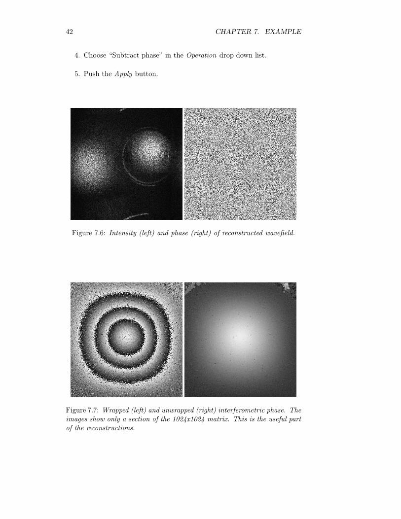
However, it is the phase difference between the two states which is of in-terest in holographic interferometry. This was obtained by subtracting thephase of one of the reconstructions from the phase of the other. This gavethe wrapped phase map modulo 2π in Fig. 7.7. Goldstein’s unwrappingalgorithm elliminated the phase steps and provided the smooth image tothe right in the aforementioned figure. The latter phase map is used in aquantitative analysis of the deformation.
To do:
1. Open the Calculation dialog box by clicking the Image Calculationsicon on the toolbar.
2. Choose “plate2 rec” in the Destination field.
3. Choose “plate1 rec” in the Source field.
42 CHAPTER 7. EXAMPLE
4. Choose “Subtract phase” in the Operation drop down list.
5. Push the Apply button.
Figure 7.6: Intensity (left) and phase (right) of reconstructed wavefield.
Figure 7.7: Wrapped (left) and unwrapped (right) interferometric phase. Theimages show only a section of the 1024x1024 matrix. This is the useful partof the reconstructions.
7.3. THE RECONSTRUCTIONS 43
To do:
1. Repeat the entire process with the plate2 and plate3 files.
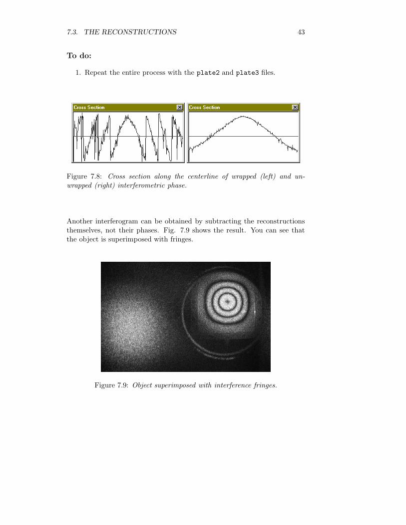
Figure 7.8: Cross section along the centerline of wrapped (left) and un-wrapped (right) interferometric phase.
Another interferogram can be obtained by subtracting the reconstructionsthemselves, not their phases. Fig. 7.9 shows the result. You can see thatthe object is superimposed with fringes.
Figure 7.9: Object superimposed with interference fringes.
Chapter 8
A Developer’s Guide - byØystein Skotheim
This text is taken from Ref. [2] and included in the user’s manual forcompleteness. Additional footnotes have been included by Vegard Tuft. Thechapter explaines how to install the HoloVision source code components forfurther development. Readers merely interested in using HoloVision, notdeveloping it, may skip this chapter.
8.1 Obtaining and Installing HoloVision
Binaries and source code for the application HoloVision as of 28th of Febru-ary 2001 is included on the attached CD-ROM1. Please visit the project’swebpage:
http://www.edge.no/projects/holovision/
or contact the author2 for a more up-to-date version before further develop-ment is done. The author can be reached via e-mail on [email protected]
To aid in the further development of this application, I have made a recipefor obtaining and configuring dependent tools and libraries. Below is a listof requirements needed to build the full version of HoloVision. Some of thelibraries may be left out as stated in the footnotes if a reduced functionalityversion is to be built.
Most of the libraries used in the development of HoloVision are publicly
1This refers to the CD-ROM that accompanied Ref. [2]2Throughout this chapther the term “the author” means the author of the developer’s
guide, i.e. Øystein Skotheim
44
8.1. OBTAINING AND INSTALLING HOLOVISION 45
available under the GNU General Public License. They are included on theCD-ROM for convenience. As a consequence, HoloVision is also releasedunder the terms of the GPL. A GNU Copyleft is enclosed in appendix Dwhich states these terms. In general, the license allows anyone to use, modifyand distribute this software, provided that the modified work is releasedunder the same license terms as the original work. A proper copyright noticeand disclaimer of warranty should be attached to each of the published copiesalong with a copy of the license terms.
8.1.1 Requirements
The following tools were used in the development of HoloVision.
• Microsoft Visual C++ version 6.0
– Compiler and integrated development environment (IDE)
• Microsoft Visual SourceSafe3
– Software for revision control
• ITEX-SDK 3.3.14
– Drivers and software for the IC-PCI framegrabber and cameradevice
• Matlab 5.35
– Advanced mathematics software and API from MathWorks
• FFTW 2.1.3
– Fast Fourier Transformation library from the Massachusetts In-stitute of Technology
• ImageMagick 5.2.6 and Magick++ API
– Software library for loading, storing and manipulating images invarious formats
3Not really required, but strongly recommended. GPL software like CVS is a free,decent alternative
4May be left out if camera control and aquirement functions for the IC-PCI framegrab-ber device and Hamamatsu digital CCD camera are not needed
5May be left out if ActiveX data transfer between Holovision and Matlab is undesired
46CHAPTER 8. A DEVELOPER’S GUIDE - BY ØYSTEIN SKOTHEIM
8.1.2 Installation
The installation process consists of several steps, and should be performed inthe order given below. The developer should be aware that failure to do somay result in dependency failures between the components of the software.
• Install Microsoft Visual C++ 6.0
– Dynamically linkable debug and release versions of the MicrosoftFoundation Classes version 4.2 libraries are required. MicrosoftDevelopers Network (MSDN) is recommended. Microsoft Install-shield was used for packaging of the binaries on the enclosed CD-ROM.
• Install Microsoft Visual SourceSafe
• Install the ITEX SDK driver and software utilities.
– This exists on a separate CD, but is included on the HoloVisionCD-ROM for conveniece in the Itex directory.
– The following dynamic libraries should be accessible to HoloVi-sion, and should reside either in the application directory or thewindows system directory:
itxavi10.dllitxdrv10.dllitxdsp10.dllitxco10.dll
• Install Matlab and export library definitions for the ActiveX API toVisual C++
– Library definitions for ActiveX calls to Matlab reside in the subdi-rectory extern/include. These definition files must be exportedto a format accessible by the MSVC++ linker. The library toollib.exe accessible from the Visual C++ directory does the trick:
lib /def:libeng.deflib /def:libmat.deflib /def:libmx.def
– The directory where the libraries and header files reside has to beadded to the library and include file search path in the projectsettings for HoloVision.
– Include the libraries libeng.lib, libmat.lib and libmx.lib inthe list of object modules for the linker
8.1. OBTAINING AND INSTALLING HOLOVISION 47
– The following runtime libraries from Matlab are needed for theapplication to run with Matlab ActiveX support:
libeng.dlllibmat.dlllibmatlbmx.dlllibmccmx.dlllibmi.dlllibmx.dlllibut.dll
• Install and configure FFTW for use as a dynamically linkable librarywith proper operational data types
– The files fftw-2.1.3.zip and FFTW2.1.3.Win32.zip are includedon the CD-ROM. Uncompress FFTW and install the Win32 Vi-sual C++ project definitions (latter file) in the subdirectory win32at the desired location.
– As HoloVision makes use of the float datatype, and FFTW usesdouble by default, a small change has to be done in the filefftw.h. Make sure to change the following line
/* #undef FFTW_ENABLE_FLOAT */
into
#define FFTW_ENABLE_FLOAT
before compiling.
– Open the workspace fftw-win32.dsw from the Integrated Devel-opment Environment and build release versions of the projectsFFTW2dll and RFFTW2dll.
– Add the directory location of FFTW to the library and headerfile search path in Visual C++ and include the library defini-tions FFTW2dll.lib and RFFTW2dll.lib in the project settingsof HoloVision.
– The symbol USE FFTW DLL should be added to the global prepro-cessor definitions.
– The two DLLs FFTW2dll.dll and RFFTW2dll.dll must be ac-cessible to the HoloVision application.
• Configure and install ImageMagick
– Uncompress the archive ImageMagick-5.2.6.zip included onthe CD to a suitable location.
48CHAPTER 8. A DEVELOPER’S GUIDE - BY ØYSTEIN SKOTHEIM
– Open and build the configure script from the workspace file configure.dswin the VisualMagick subdirectory
– Run the configure script and choose to build ImageMagick asdynamic multi-threaded DLL runtimes. X11 stubs should be usedto mask out the X windows library calls. The demo, test andcontrib programs should be included in the build for examples onhow to use ImageMagick and the Magick++ API.
– The configure scripts generates a workspace file in the VisualMagickdirectory. Load this file into the Visual Studio environment, andchoose to compile all projects.
– Binaries, library files etc. will be placed in the bin-subdirectory.The following libraries and configuration files are required byHoloVision and should be placed in the same location as theexecutable:
CORE_DB_lcms_.dllCORE_DB_magick_.dllCORE_DB_ttf_.dllCORE_DB_xlib_.dllIM_MOD_DB_bmp_.dllIM_MOD_DB_gif_.dllIM_MOD_DB_jpeg_.dllIM_MOD_DB_tiff_.dllIM_MOD_DB_xc_.dllLIBR_DB_JPEG_.dllLIBR_DB_TIFF_.dllLIBR_DB_ZLIB_.dlldelegates.mgkmagic.mgkmodules.mgkrgb.txt
– The following library definitions should be supplied to the linker:
CORE_DB_magick_.libCORE_DB_xlib_.libCORE_DB_Magick++_.lib
Also be sure to include wsock32.lib as some of the librariesare dependent on this file. The directories ImageMagick andMagick++ should be added to the include files search path.
• References to all of the dependent libraries should reside in the projectfile supplied with the source code (holovision.dsp), but you shoulddouble check the search paths in case your utilities are installed intodifferent locations!
8.1. OBTAINING AND INSTALLING HOLOVISION 49
You should now be able to compile the HoloVision project. Note that thereare two conditional defines to the preprocessor that are particularly impor-tant, namely:
#define NO_MATLAB#define NO_ITEX
If any of these symbols are defined, all references to Matlab and/ or ITEXlibraries will be left out. If ITEX is left out, all functionality related tocamera control and acquirement of live or still images will be lost. WithoutMatlab ActiveX functionality, the software will of course not be able tocommunicate directly with Matlab.
Further Documentation
Documentation6 for the different APIs used in the development of HoloVi-sion can be found in the following references: Matlab API[8][9], ImageMag-ick and Magick++[11], FFTW library[12].
6In addition, Refs. [6] and [10] provide necessary details on the Hamamtsu digitalcamera and the ITEX SDK
Appendix A
Troubleshooting
This is a guide to some known problems.
A.1 General
• During installation the Install Wizard says it is installing thefull version
– Ignore this message if you chose the Light or Matlab release.
• Error message “Invalid handle while opening port” appearswhen starting HoloVision
– Ignore it and push the OK button if you have the Light or Matlabrelease installed.
– If you have the full version of HoloVision, this message appearswhen you are starting the software and already have a HoloVi-sion window open. Camera communication may not functionproperly. In that case, close all HoloVision windows and restartthe software. You may even have to reboot your computer.
– The message can also appear if you have the full version, but notITEX installed.
• HoloVision is not responding
– Live grabbing was not stopped before doing any calculations.
• Cross Section window does not show any values
– Click somewhere in the Cross Section window and then click anyopen HVM matrix.
50
A.2. CAMERA COMMUNICATION 51
• Print Preview shows a bigger image than the actual print
– Printing functions have not been implemented in HoloVision.
• The WYKO Vision32 Parameters dialog box does not openwhen exporting to WYKO Vision32 dataset
– Make sure you entered no file extension or one of the extensions“asc” and “ASC” (not “aSc” or something else) when you savedthe file.
A.2 Camera Communication
See also the Hamamatsu instruction manual (Ref. [6]).
• All items in the Camera menu are unavailable
– Install the full version of HoloVision.
• No response from camera
– Make sure the camera is connected and switched on.
– Exit HoloVision and restart the software. A computer rebootmay be necessary.
• Grabbed image does not have the selected resolution
– Remember to click the Apply button before closing the CameraSetup dialog box.
• Update of live grabbing is very slow
– Live grabbing in full resolution mode is not recommended.
– You may have too many programs open at the same time.
• HoloVision is not responding
– You may have started live grabbing two consecutive times.
– You may have started a calculation before stopping live grabbing.
52 APPENDIX A. TROUBLESHOOTING
A.3 Matlab
• All items in the Matlab menu are unavailable
– Install the Matlab release or full version of HoloVision.
• Error message “Failed to open engine” appears when openingMatlab engine
– Make sure Matlab is installed on your computer.
– If Matlab is installed, check which version. Versions older than5.3 may not support engine operations. The engine does not seemto work with the new 6.0 version.
– If it is the first time you are using the engine, you may have toopen Matlab manually before starting the engine.
• Error message “Unable to put array into Matlab” appearswhen sending arrays to Matlab
– This message appears if Matlab was closed manually while anengine was still running. Stop and restart the engine.
• Matlab does not close when the engine was stopped
– It may take some time before Matlab exits.
– Close Matlab manually if it still does not exit.
Appendix B
Mathematical Reference
This appendix summarizes the mathematical formulae used in HoloVision.
B.1 List of Symbols
amn The real part of element (m,n) of the HoloVision matrixα Tilt angle 1, horizontal directionbmn The imaginary part of element (m,n) of the HoloVision
matrixβ Tilt angle 2, vertical direction∆ξ Pixel size (detector pitch) of the CCD chip∆x′ Pixel size in reconstructed image, i.e. in the image planeλ Wavelength of the lightwavesθ Angular extent of objectθmax Max. allowed angular extent θ of objectb′(n,m) The reconstructed wavefield in the image planed Distance between object and hologram plane (CCD)d′ Distance between hologram plane (CCD) and
reconstruction (image) planeD Object size (i.e. width or height)ddf Defocus distanceDmax Max. allowed object size Ddref Distance between hologram plane (CCD) and
reference wave sourceDFT{m} The discrete two-dimensional Fourier transform of the
function or matrix mf Focal length of the numerical lensh(k, l) Hologramh′(k, l) Filtered hologram
53
54 APPENDIX B. MATHEMATICAL REFERENCE
IDFT{m} The discrete two-dimensional inverse Fourier transformof the function m
M Number of pixels in one dimensionMF The value of MNL required to get the same image with the
convolution method as with the Fresnel methodMNL Magnification of numerical lens used in the convolution
methodN Number of pixels in one dimensiono(k, l) Object waver(k, l) Reference wavez Cartesian coordinate along the optical axis
B.2 The HoloVison Matrix
The HoloVision matrix consists of elements with complex values. Element(m,n), where m denotes the row number and n the coloumn number, can bewritten as the expression amn + bmni. a is the real part, b is the imaginarypart, and i is the imaginary unit defined by i =
√−1.
B.3 Show Values
Specifies what part of the matrix to display on the screen.
Real: amn
Imaginary: bmn
Modulus:√
a2mn + b2
mn
Phase: arctan(
bmnamn
)modulo 2π
Intensity: a2mn + b2
mn
Log(Intensity): log10(a2mn + b2
mn)
B.4 The Calculator
Min. distance between object and hologram plane:
d =2∆ξD
λ(B.1)
B.5. FOURIER TRANSFORMS 55
Max. allowed object size:
Dmax =λd
2∆ξ(B.2)
Max. allowed angular extent of object:
θmax = arcsin(λ
2∆ξ) (B.3)
Pixel size in the reconstruction plane (Fresnel method):
∆x′ =λd′
N∆ξ(B.4)
Magnification (convolution method):
MF =N(∆ξ)2
λd′(B.5)
B.5 Fourier Transforms
The discrete two-dimensional Fourier transform DFT{m} of a function ormatrix m is defined as
DFT{m} =N−1∑k=0
M−1∑l=0
me−2πi(nkN
+ mlM
) (B.6)
in HoloVision.
IDFT{m} =N−1∑k=0
M−1∑l=0
me2πi(nkN
+ mlM
) (B.7)
is the inverse transform.
A transform followed by an inverse transform will multiply the matrix byN · M .
56 APPENDIX B. MATHEMATICAL REFERENCE
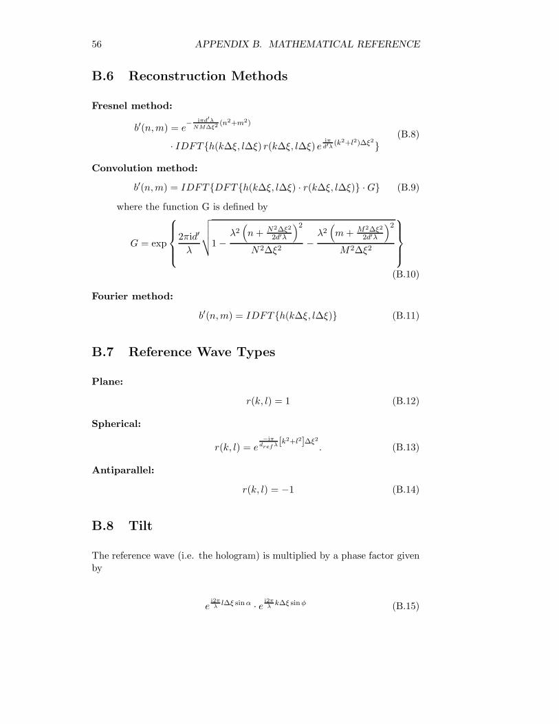
B.6 Reconstruction Methods
Fresnel method:
b′(n,m) = e− iπd′λ
NM∆ξ2(n2+m2)
· IDFT{h(k∆ξ, l∆ξ) r(k∆ξ, l∆ξ) eiπ
d′λ (k2+l2)∆ξ2}(B.8)
Convolution method:
b′(n,m) = IDFT{DFT{h(k∆ξ, l∆ξ) · r(k∆ξ, l∆ξ)} · G} (B.9)
where the function G is defined by
G = exp
2πid′
λ
√√√√1 −
λ2(n + N2∆ξ2
2d′λ
)2
N2∆ξ2−
λ2(m + M2∆ξ2
2d′λ
)2
M2∆ξ2
(B.10)
Fourier method:
b′(n,m) = IDFT{h(k∆ξ, l∆ξ)} (B.11)
B.7 Reference Wave Types
Plane:
r(k, l) = 1 (B.12)
Spherical:
r(k, l) = e−iπ
dref λ [k2+l2]∆ξ2
. (B.13)
Antiparallel:
r(k, l) = −1 (B.14)
B.8 Tilt
The reference wave (i.e. the hologram) is multiplied by a phase factor givenby
ei2πλ
l∆ξ sin α · e i2πλ
k∆ξ sinφ (B.15)
B.9. FILTERS 57
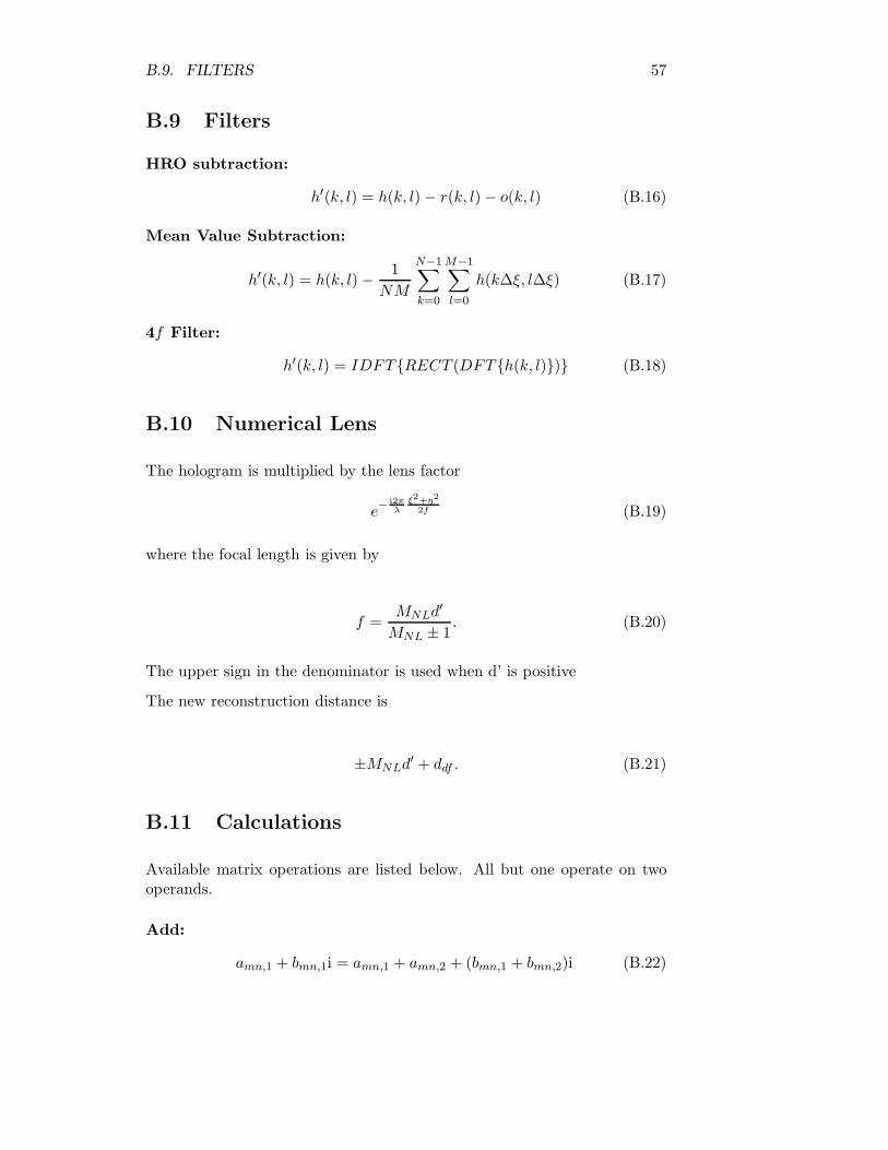
B.9 Filters
HRO subtraction:
h′(k, l) = h(k, l) − r(k, l) − o(k, l) (B.16)
Mean Value Subtraction:
h′(k, l) = h(k, l) − 1NM
N−1∑k=0
M−1∑l=0
h(k∆ξ, l∆ξ) (B.17)
4f Filter:
h′(k, l) = IDFT{RECT (DFT{h(k, l)})} (B.18)
B.10 Numerical Lens
The hologram is multiplied by the lens factor
e− i2π
λξ2+η2
2f (B.19)
where the focal length is given by
f =MNLd′
MNL ± 1. (B.20)
The upper sign in the denominator is used when d’ is positive
The new reconstruction distance is
±MNLd′ + ddf . (B.21)
B.11 Calculations
Available matrix operations are listed below. All but one operate on twooperands.
Add:
amn,1 + bmn,1i = amn,1 + amn,2 + (bmn,1 + bmn,2)i (B.22)
58 APPENDIX B. MATHEMATICAL REFERENCE
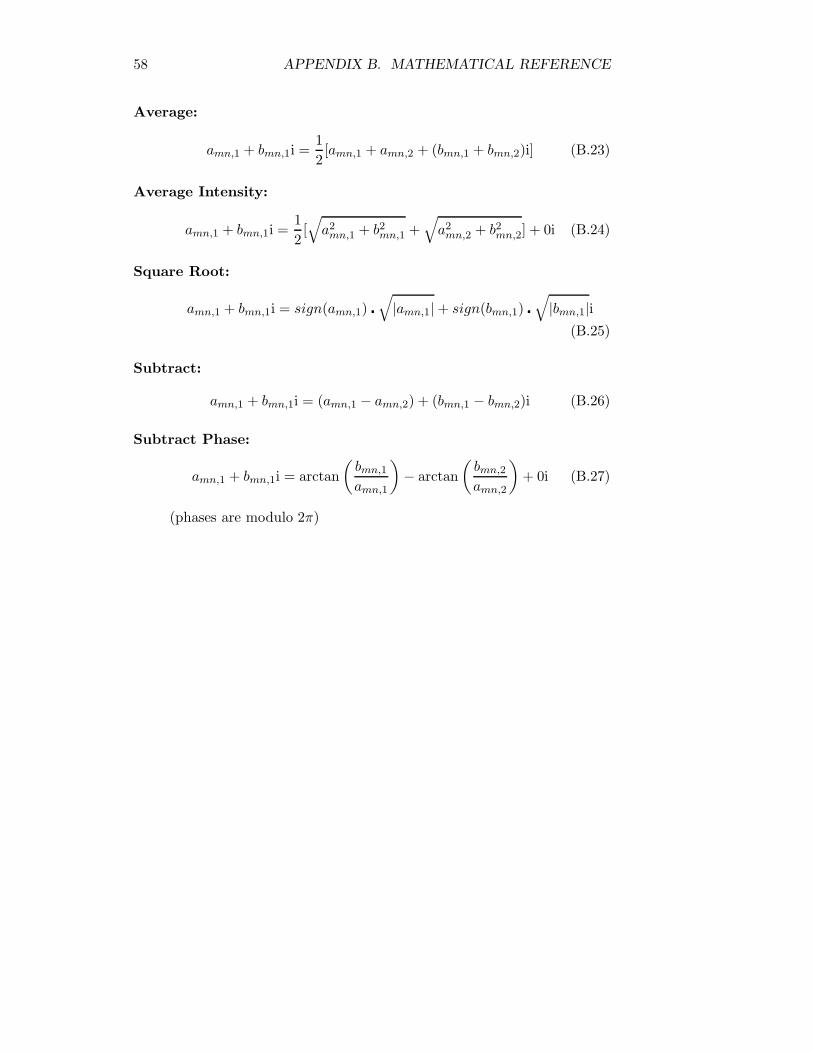
Average:
amn,1 + bmn,1i =12[amn,1 + amn,2 + (bmn,1 + bmn,2)i] (B.23)
Average Intensity:
amn,1 + bmn,1i =12[√
a2mn,1 + b2
mn,1 +√
a2mn,2 + b2
mn,2] + 0i (B.24)
Square Root:
amn,1 + bmn,1i = sign(amn,1) �√
|amn,1| + sign(bmn,1) �√
|bmn,1|i(B.25)
Subtract:
amn,1 + bmn,1i = (amn,1 − amn,2) + (bmn,1 − bmn,2)i (B.26)
Subtract Phase:
amn,1 + bmn,1i = arctan(
bmn,1
amn,1
)− arctan
(bmn,2
amn,2
)+ 0i (B.27)
(phases are modulo 2π)
Appendix C
Shortcut Keys
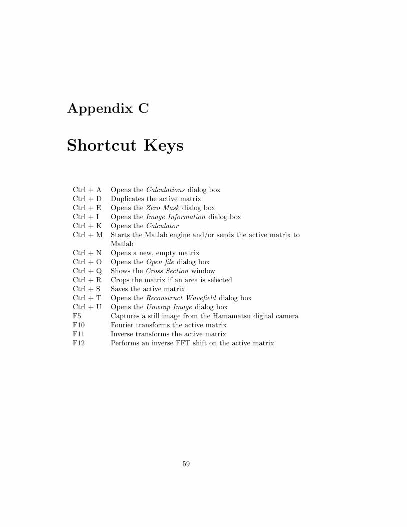
Ctrl + A Opens the Calculations dialog boxCtrl + D Duplicates the active matrixCtrl + E Opens the Zero Mask dialog boxCtrl + I Opens the Image Information dialog boxCtrl + K Opens the CalculatorCtrl + M Starts the Matlab engine and/or sends the active matrix to
MatlabCtrl + N Opens a new, empty matrixCtrl + O Opens the Open file dialog boxCtrl + Q Shows the Cross Section windowCtrl + R Crops the matrix if an area is selectedCtrl + S Saves the active matrixCtrl + T Opens the Reconstruct Wavefield dialog boxCtrl + U Opens the Unwrap Image dialog boxF5 Captures a still image from the Hamamatsu digital cameraF10 Fourier transforms the active matrixF11 Inverse transforms the active matrixF12 Performs an inverse FFT shift on the active matrix
59
Appendix D
The GNU General PublicLicence
The following is the text of the GNU General Public Licence, under theterms of which the accompanying software is distributed.
GNU GENERAL PUBLIC LICENSEVersion 2, June 1991
Copyright (C) 1989, 1991 Free Software Foundation, Inc.675 Mass Ave, Cambridge, MA 02139, USA
Everyone is permitted to copy and distribute verbatim copiesof this license document, but changing it is not allowed.
Preamble
The licenses for most software are designed to take away your freedom toshare and change it. By contrast, the GNU General Public License is in-tended to guarantee your freedom to share and change free software—tomake sure the software is free for all its users. This General Public Li-cense applies to most of the Free Software Foundation’s software and to anyother program whose authors commit to using it. (Some other Free SoftwareFoundation software is covered by the GNU Library General Public Licenseinstead.) You can apply it to your programs, too.
When we speak of free software, we are referring to freedom, not price.Our General Public Licenses are designed to make sure that you have the
60
61
freedom to distribute copies of free software (and charge for this service ifyou wish), that you receive source code or can get it if you want it, that youcan change the software or use pieces of it in new free programs; and thatyou know you can do these things.
To protect your rights, we need to make restrictions that forbid anyone todeny you these rights or to ask you to surrender the rights. These restrictionstranslate to certain responsibilities for you if you distribute copies of thesoftware, or if you modify it.
For example, if you distribute copies of such a program, whether gratis orfor a fee, you must give the recipients all the rights that you have. You mustmake sure that they, too, receive or can get the source code. And you mustshow them these terms so they know their rights.
We protect your rights with two steps: (1) copyright the software, and (2)offer you this license which gives you legal permission to copy, distributeand/or modify the software.
Also, for each author’s protection and ours, we want to make certain thateveryone understands that there is no warranty for this free software. If thesoftware is modified by someone else and passed on, we want its recipientsto know that what they have is not the original, so that any problemsintroduced by others will not reflect on the original authors’ reputations.
Finally, any free program is threatened constantly by software patents. Wewish to avoid the danger that redistributors of a free program will individ-ually obtain patent licenses, in effect making the program proprietary. Toprevent this, we have made it clear that any patent must be licensed foreveryone’s free use or not licensed at all.
The precise terms and conditions for copying, distribution and modificationfollow.
Terms and conditions for copying, distribution andmodification
0. This License applies to any program or other work which contains anotice placed by the copyright holder saying it may be distributedunder the terms of this General Public License. The “Program”, be-low, refers to any such program or work, and a “work based on theProgram” means either the Program or any derivative work undercopyright law: that is to say, a work containing the Program or aportion of it, either verbatim or with modifications and/or translatedinto another language. (Hereinafter, translation is included without
62 APPENDIX D. THE GNU GENERAL PUBLIC LICENCE
limitation in the term “modification”.) Each licensee is addressed as“you”.
Activities other than copying, distribution and modification are notcovered by this License; they are outside its scope. The act of runningthe Program is not restricted, and the output from the Program iscovered only if its contents constitute a work based on the Program(independent of having been made by running the Program). Whetherthat is true depends on what the Program does.
1. You may copy and distribute verbatim copies of the Program’s sourcecode as you receive it, in any medium, provided that you conspicuouslyand appropriately publish on each copy an appropriate copyright no-tice and disclaimer of warranty; keep intact all the notices that referto this License and to the absence of any warranty; and give any otherrecipients of the Program a copy of this License along with the Pro-gram.
You may charge a fee for the physical act of transferring a copy, andyou may at your option offer warranty protection in exchange for afee.
2. You may modify your copy or copies of the Program or any portionof it, thus forming a work based on the Program, and copy and dis-tribute such modifications or work under the terms of Section 1 above,provided that you also meet all of these conditions:
(a) You must cause the modified files to carry prominent notices stat-ing that you changed the files and the date of any change.
(b) You must cause any work that you distribute or publish, that inwhole or in part contains or is derived from the Program or anypart thereof, to be licensed as a whole at no charge to all thirdparties under the terms of this License.
(c) If the modified program normally reads commands interactivelywhen run, you must cause it, when started running for such in-teractive use in the most ordinary way, to print or display anannouncement including an appropriate copyright notice and anotice that there is no warranty (or else, saying that you providea warranty) and that users may redistribute the program underthese conditions, and telling the user how to view a copy of thisLicense. (Exception: if the Program itself is interactive but doesnot normally print such an announcement, your work based onthe Program is not required to print an announcement.)
These requirements apply to the modified work as a whole. If identifi-able sections of that work are not derived from the Program, and can
63
be reasonably considered independent and separate works in them-selves, then this License, and its terms, do not apply to those sectionswhen you distribute them as separate works. But when you distributethe same sections as part of a whole which is a work based on theProgram, the distribution of the whole must be on the terms of thisLicense, whose permissions for other licensees extend to the entirewhole, and thus to each and every part regardless of who wrote it.
Thus, it is not the intent of this section to claim rights or contest yourrights to work written entirely by you; rather, the intent is to exercisethe right to control the distribution of derivative or collective worksbased on the Program.
In addition, mere aggregation of another work not based on the Pro-gram with the Program (or with a work based on the Program) on avolume of a storage or distribution medium does not bring the otherwork under the scope of this License.
3. You may copy and distribute the Program (or a work based on it,under Section 2) in object code or executable form under the terms ofSections 1 and 2 above provided that you also do one of the following:
(a) Accompany it with the complete corresponding machine-readablesource code, which must be distributed under the terms of Sec-tions 1 and 2 above on a medium customarily used for softwareinterchange; or,
(b) Accompany it with a written offer, valid for at least three years,to give any third party, for a charge no more than your cost ofphysically performing source distribution, a complete machine-readable copy of the corresponding source code, to be distributedunder the terms of Sections 1 and 2 above on a medium custom-arily used for software interchange; or,
(c) Accompany it with the information you received as to the offer todistribute corresponding source code. (This alternative is allowedonly for noncommercial distribution and only if you received theprogram in object code or executable form with such an offer, inaccord with Subsection b above.)
The source code for a work means the preferred form of the work formaking modifications to it. For an executable work, complete sourcecode means all the source code for all modules it contains, plus anyassociated interface definition files, plus the scripts used to controlcompilation and installation of the executable. However, as a specialexception, the source code distributed need not include anything thatis normally distributed (in either source or binary form) with the major
64 APPENDIX D. THE GNU GENERAL PUBLIC LICENCE
components (compiler, kernel, and so on) of the operating system onwhich the executable runs, unless that component itself accompaniesthe executable.
If distribution of executable or object code is made by offering accessto copy from a designated place, then offering equivalent access tocopy the source code from the same place counts as distribution of thesource code, even though third parties are not compelled to copy thesource along with the object code.
4. You may not copy, modify, sublicense, or distribute the Program ex-cept as expressly provided under this License. Any attempt otherwiseto copy, modify, sublicense or distribute the Program is void, and willautomatically terminate your rights under this License. However, par-ties who have received copies, or rights, from you under this Licensewill not have their licenses terminated so long as such parties remainin full compliance.
5. You are not required to accept this License, since you have not signedit. However, nothing else grants you permission to modify or distributethe Program or its derivative works. These actions are prohibited bylaw if you do not accept this License. Therefore, by modifying ordistributing the Program (or any work based on the Program), youindicate your acceptance of this License to do so, and all its termsand conditions for copying, distributing or modifying the Program orworks based on it.
6. Each time you redistribute the Program (or any work based on theProgram), the recipient automatically receives a license from the orig-inal licensor to copy, distribute or modify the Program subject to theseterms and conditions. You may not impose any further restrictions onthe recipients’ exercise of the rights granted herein. You are not re-sponsible for enforcing compliance by third parties to this License.
7. If, as a consequence of a court judgment or allegation of patent in-fringement or for any other reason (not limited to patent issues), con-ditions are imposed on you (whether by court order, agreement orotherwise) that contradict the conditions of this License, they do notexcuse you from the conditions of this License. If you cannot distributeso as to satisfy simultaneously your obligations under this License andany other pertinent obligations, then as a consequence you may notdistribute the Program at all. For example, if a patent license wouldnot permit royalty-free redistribution of the Program by all those whoreceive copies directly or indirectly through you, then the only wayyou could satisfy both it and this License would be to refrain entirelyfrom distribution of the Program.
65
If any portion of this section is held invalid or unenforceable under anyparticular circumstance, the balance of the section is intended to applyand the section as a whole is intended to apply in other circumstances.
It is not the purpose of this section to induce you to infringe anypatents or other property right claims or to contest validity of any suchclaims; this section has the sole purpose of protecting the integrity ofthe free software distribution system, which is implemented by publiclicense practices. Many people have made generous contributions tothe wide range of software distributed through that system in relianceon consistent application of that system; it is up to the author/donorto decide if he or she is willing to distribute software through any othersystem and a licensee cannot impose that choice.
This section is intended to make thoroughly clear what is believed tobe a consequence of the rest of this License.
8. If the distribution and/or use of the Program is restricted in certaincountries either by patents or by copyrighted interfaces, the originalcopyright holder who places the Program under this License may addan explicit geographical distribution limitation excluding those coun-tries, so that distribution is permitted only in or among countries notthus excluded. In such case, this License incorporates the limitationas if written in the body of this License.
9. The Free Software Foundation may publish revised and/or new ver-sions of the General Public License from time to time. Such newversions will be similar in spirit to the present version, but may differin detail to address new problems or concerns.
Each version is given a distinguishing version number. If the Programspecifies a version number of this License which applies to it and “anylater version”, you have the option of following the terms and condi-tions either of that version or of any later version published by theFree Software Foundation. If the Program does not specify a versionnumber of this License, you may choose any version ever published bythe Free Software Foundation.
10. If you wish to incorporate parts of the Program into other free pro-grams whose distribution conditions are different, write to the authorto ask for permission. For software which is copyrighted by the FreeSoftware Foundation, write to the Free Software Foundation; we some-times make exceptions for this. Our decision will be guided by the twogoals of preserving the free status of all derivatives of our free softwareand of promoting the sharing and reuse of software generally.
NO WARRANTY
66 APPENDIX D. THE GNU GENERAL PUBLIC LICENCE
11. Because the Program is licensed free of charge, there is nowarranty for the Program, to the extent permitted by ap-plicable law. except when otherwise stated in writing thecopyright holders and/or other parties provide the program“as is” without warranty of any kind, either expressed or im-plied, including, but not limited to, the implied warrantiesof merchantability and fitness for a particular purpose. Theentire risk as to the quality and performance of the Programis with you. Should the Program prove defective, you assumethe cost of all necessary servicing, repair or correction.
12. In no event unless required by applicable law or agreed toin writing will any copyright holder, or any other party whomay modify and/or redistribute the program as permittedabove, be liable to you for damages, including any general,special, incidental or consequential damages arising out ofthe use or inability to use the program (including but notlimited to loss of data or data being rendered inaccurate orlosses sustained by you or third parties or a failure of theProgram to operate with any other programs), even if suchholder or other party has been advised of the possibility ofsuch damages.
END OF TERMS AND CONDITIONS
Appendix E
CD-ROM Contents
This appendix lists the contents of the accompanying CD-ROM and itsdirectories.
E.1 Holovision 2.2.1 Win32 Install Binary
The installation files for HoloVision 2.2.1 are placed in the main directoryof the CD. Run setup.exe to install the software if the setup program doesnot start automatically.
HoloVision 2.2 is distributed under the GNU General Public License foundin the license.txt file or in App. D.
E.2 Documentation
Documentation can be found in the doc directory.
• project.pdf : Numerisk rekonstruksjon av hologrammer i digital holo-grafi ; Øystein Skotheim’s and Vegard L. Tuft’s joint project 1999/2000(Ref. [1]).
• thesis os: HoloVision - a software package for reconstruction andanalysis of digitally sampled holograms; Øystein Skotheim’s diplomathesis 2001 (Ref. [2]); ps and pdf formats.
• thesis vlt: Fringe resolution in digital holographic interferometry ; Ve-gard L. Tuft’s diploma thesis 2001 (Ref. [3]); ps and pdf formats.
67
68 APPENDIX E. CD-ROM CONTENTS
• hv manual: HoloVision 2.2 User’s Manual in pdf and ps formats;covers HoloVision 2.2.1.
E.3 Holograms
The recordings mentioned in Chapter 7 are included in the holograms direc-tory.
• plate1 hologram.hvm: Hologram of initial state of object
• plate1 object.hvm: Object wave
• plate1 reference.hvm: Reference wave
• plate2 hologram.hvm: Hologram of loaded state of object
• plate2 object.hvm: Object wave
• plate2 reference.hvm: Reference wave
• plate3 hologram.hvm: Hologram of loaded state of object
• plate3 object.hvm: Object wave
• plate3 reference.hvm: Reference wave
Compare plate1 and plate2 OR plate2 and plate3 interferometrically to pro-duce fringes.
E.4 Setup Images
Pictures of the object and experimental arrangement described in Chapter7 are included in the setup images directory.
Bibliography
[1] Øystein Skotheim, Vegard L. TuftNumerisk rekonstruksjon av hologrammer i digital holografiGroup of Technical Optics, Department of Physics, NorwegianUniversity of Science and Technology, 2000
[2] Øystein SkotheimHoloVision - a Software Package for Reconstruction and Analysisof Digitally Sampled HologramsGroup of Technical Optics, Department of Physics, NorwegianUniversity of Science and Technology, 2001
[3] Vegard L. TuftFringe resolution in digital holographic interferometryGroup of Technical Optics, Department of Physics, NorwegianUniversity of Science and Technology, 2001
[4] Hans Rossavik GundersenImplementation and Comparison of Phase Unwrapping Techniquesfor a Shape Measuring InstrumentGroup of Technical Optics, Department of Physics, NorwegianUniversity of Science and Technology, 1999
[5] Thomas M. Kreis, Mike Adams, Werner P.O. JuptnerMethods of Digital Holography: A ComparisonProc. SPIE vol. 3098, 224-233, 1997
[6] HamamtsuDigital CCD Camera C4742-95 Instruction ManualHamamatsu Photonics, 1996
[7] MathWorksGetting started with Matlab (version 5)The MathWorks, Inc., 1998
69

70 BIBLIOGRAPHY
[8] MathWorksMatlab Application Program Interface Guide (version 5)The MathWorks, Inc., 1998
[9] MathworksMatlab Application Program Interface Reference (version 5)The MathWorks, Inc., 1998
[10] Imaging TechnologyITEX-IC System Level Software ManualImaging Technology Inc., 1998
[11] ImageMagick StudioImageMagick User’s Guidehttp://www.simplesystems.org/Magick++/
[12] Matteo Frigo and Steven G. JohnsonFFTW User’s manualhttp://www.fftw.org/