hollow-shaft motors for main spindle drives 1pm6/1pm4
TRANSCRIPT

Foreword
1
Electrical Data 2
Mechanical Data 3
Order Designation 4
5
Dimension Drawings 6
Appendix A
Technical Data and Characteristics
Description of the Hollow-Shaft Motor
SIMODRIVE
Hollow-Shaft Motors for Main Spindle Drives 1PM6/1PM4
Configuration Manual
(PPM), 08/2005 Edition 6SN1197-0AD03-0BP1

Safety Guidelines
This manual contains notices you have to observe in order to ensure your personal safety, as well as to prevent damage to property. The notices referring to your personal safety are highlighted in the manual by a safety alert symbol, notices referring only to property damage have no safety alert symbol. These notices shown below are graded according to the degree of danger.
Danger
indicates that death or severe personal injury will result if proper precautions are not taken.
Warning
indicates that death or severe personal injury may result if proper precautions are not taken.
Caution
with a safety alert symbol, indicates that minor personal injury can result if proper precautions are not taken.
Caution
without a safety alert symbol, indicates that property damage can result if proper precautions are not taken.
Notice
indicates that an unintended result or situation can occur if the corresponding information is not taken into account.
If more than one degree of danger is present, the warning notice representing the highest degree of danger will be used. A notice warning of injury to persons with a safety alert symbol may also include a warning relating to property damage.
Qualified Personnel The device/system may only be set up and used in conjunction with this documentation. Commissioning and operation of a device/system may only be performed by qualified personnel. Within the context of the safety notes in this documentation qualified persons are defined as persons who are authorized to commission, ground and label devices, systems and circuits in accordance with established safety practices and standards.
Prescribed Usage Note the following:
Warning
This device may only be used for the applications described in the catalog or the technical description and only in connection with devices or components from other manufacturers which have been approved or recommended by Siemens. Correct, reliable operation of the product requires proper transport, storage, positioning and assembly as well as careful operation and maintenance.
Trademarks All names identified by ® are registered trademarks of the Siemens AG. The remaining trademarks in this publication may be trademarks whose use by third parties for their own purposes could violate the rights of the owner.
Disclaimer of Liability We have reviewed the contents of this publication to ensure consistency with the hardware and software described. Since variance cannot be precluded entirely, we cannot guarantee full consistency. However, the information in this publication is reviewed regularly and any necessary corrections are included in subsequent editions.
Siemens AG rives
Postfach 48 48 90437 NÜRNBERG
Order No.: 6SN1197-0AD03-0BP1 08/2005 Edition
Copyright © Siemens AG 2001-2005.
ect to change Technical data subj
GERMANY
Automation and D

Foreword Information on SIMODRIVE documentation
This document is part of the Technical Customer Documentation which has been developed for the SIMODRIVE system. All of the documents are available individually. The documentation list, which includes all Advertising Brochures, Catalogs, Overviews, Short Descriptions, Operating Instructions and Technical Descriptions with Order No., ordering address and price can be obtained from your local Siemens office.
This document does not purport to cover all details or variations in equipment, nor to provide for every possible contingency to be met in connection with installation, operation or maintenance.
We would also like to point-out that the contents of this document are neither part of nor modify any prior or existing agreement, commitment or contractual relationship. The sales contract contains the entire obligations of Siemens. The warranty contained in the contract between the parties is the sole warranty of Siemens. Any statements contained herein neither create new warranties nor modify the existing warranty.
Technical Support If you have any questions, please contact the following Hotline:
Phone: +49 (0) 180 5050–222 Fax: +49 (0) 180 5050–223 Internet: http://www.siemens.com/automation/support-request
Please send any questions about the documentation (e.g. suggestions for improvement, corrections) to the following fax number or email address:
Fax: +49 (0) 9131 98–2176 Fax form: Refer to the correction sheet at the end of the document E-mail: [email protected]
Information on the products Up-to-date information about our products can be found on the Internet at the following address:
http://www.siemens.com/motioncontrol
Hollow-Shaft Motors for Main Spindle Drives 1PM6/1PM4 Configuration Manual, (PPM), 08/2005 Edition, 6SN1197-0AD03-0BP1 iii

Foreword
Danger and warning information
Danger Start-up/commissioning is absolutely prohibited until it has been completely ensured that the machine, in which the components described here are to be installed, is in full compliance with the specifications of Directive 98/37/EC.
Only appropriately qualified personnel may commission/start-up the SIMODRIVE units and the motors.
This personnel must carefully observe the technical customer documentation associated with this product and be knowledgeable about and carefully observe the danger and warning information.
Operational electrical equipment and motors have parts and components which are at hazardous voltage levels.
When the machine or system is operated, hazardous axis movements can occur.
All of the work carried-out on the electrical machine or system must be carried-out with it in a no-voltage condition.
SIMODRIVE drive units are designed for operation on low-ohmic, grounded line supplies (TN line supplies).
SIMODRIVE drive units with motors may only be connected to the line supply through residual-current operated circuit-breakers, if corresponding to EN 50178, Chapter 5.2.11.2, it has been clearly proven that the SIMODRIVE unit is compatible with the residual-current operated circuit-breaker.
Warning The successful and safe operation of this equipment and motors is dependent on professional transport, storage, installation and mounting as well as careful operator control, service and maintenance.
For special versions of the drive units and motors, information and data in the catalogs and quotations additionally apply.
In addition to the danger and warning information/instructions in the technical customer documentation supplied, the applicable domestic, local and plant-specific regulations and requirements must be carefully taken into account.
Caution The motors can have surface temperatures of over +100° C.
This is the reason that temperature-sensitive components, e.g. cables or electronic components may neither be in contact nor be attached to the motor.
When connecting-up cables, please observe that they – are not damaged – are not subject to tensile stress – cannot be touched by rotating components.
Hollow-Shaft Motors for Main Spindle Drives 1PM6/1PM4 iv Configuration Manual, (PPM), 08/2005 Edition, 6SN1197-0AD03-0BP1
Foreword
Caution SIMODRIVE drive units with motors are subject to a voltage test, in compliance with EN 50178 as part of a routine test. While the electrical equipment of industrial machines is being subject to a voltage test in accordance with EN60204-1, Section 19.4, all SIMODRIVE drive unit connections must be disconnected/withdrawn in order to avoid damaging the SIMODRIVE drive units.
Motors should be connected-up according to the circuit diagram provided. They must not be connected directly to the three-phase supply because this will damage them.
Note SIMODRIVE units with motors fulfill, when operational and in dry operating rooms, the Low-Voltage Directive 73/23/EEC.
SIMODRIVE units with motors fulfill, in the configuration specified in the associated EC Declaration of Conformity, the EMC Directive 89/336/EEC.
Hollow-Shaft Motors for Main Spindle Drives 1PM6/1PM4 Configuration Manual, (PPM), 08/2005 Edition, 6SN1197-0AD03-0BP1 v

Foreword
ESDS instructions
Caution ElectroStatic-Sensitive Devices (ESDS) are individual components, integrated circuits, or modules that can be damaged by electrostatic fields or discharges.
ESDS regulations for handling boards and equipment:
When handling components that can be destroyed by electrostatic discharge, it must be ensured that personnel, the workstation and packaging are well grounded!
Personnel in ESD zones with conductive floors may only touch electronic components if they are – grounded through an ESDS bracelet and – wearing ESDS shoes or ESDS shoe grounding strips.
Electronic boards may only be touched when absolutely necessary.
Electronic boards may not be brought into contact with plastics and articles of clothing manufactured from man-made fibers.
Electronic boards may only be placed on conductive surfaces (table with ESDS surface, conductive ESDS foam rubber, ESDS packing bag, ESDS transport containers).
Electronic boards may not be brought close to data terminals, monitors or television sets. Minimum clearance to screens > 10 cm).
Measurements may only be carried-out on electronic boards and modules if – the measuring instrument is grounded (e.g. via a protective conductor) or – before making measurements with a potential-free measuring device, the measuring head is briefly discharged (e.g. by touching an unpainted blank piece of metal on the control cabinet).
Hollow-Shaft Motors for Main Spindle Drives 1PM6/1PM4 vi Configuration Manual, (PPM), 08/2005 Edition, 6SN1197-0AD03-0BP1

Table of contents Foreword ...................................................................................................................................................... iii
1 Description of the Hollow-Shaft Motor....................................................................................................... 1-1
1.1 Features of the 1PM6 ................................................................................................................ 1-1
1.2 Features of the 1PM4 ................................................................................................................ 1-3
1.3 Technical design, 1PM6 and 1PM4 ........................................................................................... 1-5
1.4 Technical data............................................................................................................................ 1-6 1.4.1 Technical data 1PM6 ................................................................................................................. 1-6 1.4.2 Technical data 1PM4 ................................................................................................................. 1-8
2 Electrical Data ........................................................................................................................................... 2-1
2.1 Definitions .................................................................................................................................. 2-1
2.2 Mode of operation and power characteristics ............................................................................ 2-3
2.3 Operation on SIMODRIVE 611.................................................................................................. 2-6
2.4 Motor drive converter assignment (power unit) ......................................................................... 2-7
2.5 Motor limits................................................................................................................................. 2-7
2.6 Connection system .................................................................................................................... 2-8 2.6.1 Star/delta circuit configuration.................................................................................................... 2-9 2.6.2 Power cable ............................................................................................................................. 2-10 2.6.3 Connecting-up information....................................................................................................... 2-13 2.6.4 Motor rating plate ..................................................................................................................... 2-14
2.7 Thermal motor protection......................................................................................................... 2-15
2.8 Encoders .................................................................................................................................. 2-17
3 Mechanical Data........................................................................................................................................ 3-1
3.1 Types of construction................................................................................................................. 3-1
3.2 Vibration severity limit values..................................................................................................... 3-1
3.3 Bearing design ........................................................................................................................... 3-4 3.3.1 Drive output types and bearing versions ................................................................................... 3-4 3.3.2 Bearing change intervals ........................................................................................................... 3-5 3.3.3 Cantilever and axial forces......................................................................................................... 3-6
3.4 Cooling ....................................................................................................................................... 3-8 3.4.1 Cooling-lubricating medium gland.............................................................................................. 3-9 3.4.2 Liquid cooling (oil) .................................................................................................................... 3-15 3.4.3 Liquid cooling (water)............................................................................................................... 3-16 3.4.4 Forced ventilation..................................................................................................................... 3-19
Hollow-Shaft Motors for Main Spindle Drives 1PM6/1PM4 Configuration Manual, (PPM), 08/2005 Edition, 6SN1197-0AD03-0BP1 vii

Table of contents
4 Order Designation ..................................................................................................................................... 4-1
4.1 Order No. 1PM6 ......................................................................................................................... 4-1
4.2 Order No. for 1PM4.................................................................................................................... 4-2
4.3 Ordering examples for the 1PM4 series .................................................................................... 4-3
5 Technical Data and Characteristics........................................................................................................... 5-1
5.1 Power-speed and torque-speed diagrams................................................................................. 5-1 5.1.1 1PM6 force-ventilated, 1PM4 oil-cooled .................................................................................... 5-2 5.1.2 1PM4 water-cooled .................................................................................................................. 5-12
6 Dimension Drawings.................................................................................................................................. 6-1
A Appendix....................................................................................................................................................A-1
A.1 References.................................................................................................................................A-1
Index ................................................................................................................................................... Index-1
Hollow-Shaft Motors for Main Spindle Drives 1PM6/1PM4 viii Configuration Manual, (PPM), 08/2005 Edition, 6SN1197-0AD03-0BP1
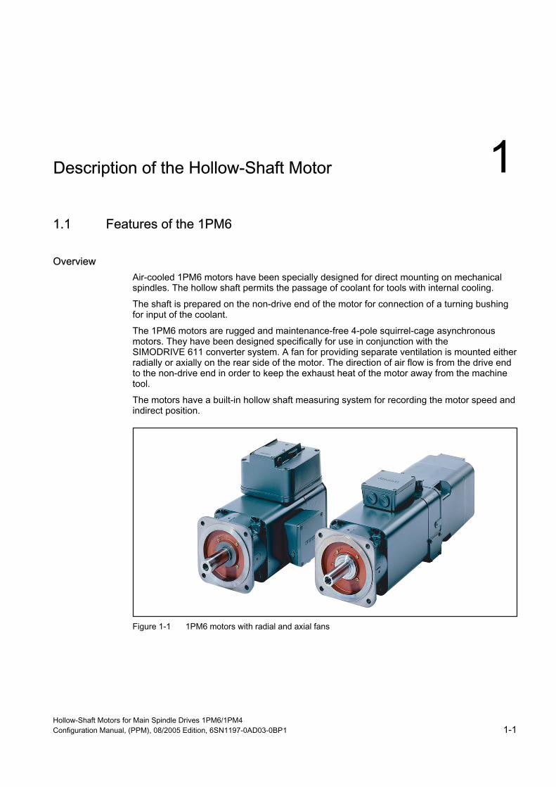
Description of the Hollow-Shaft Motor 1 1.1 Features of the 1PM6
Overview Air-cooled 1PM6 motors have been specially designed for direct mounting on mechanical spindles. The hollow shaft permits the passage of coolant for tools with internal cooling.
The shaft is prepared on the non-drive end of the motor for connection of a turning bushing for input of the coolant.
The 1PM6 motors are rugged and maintenance-free 4-pole squirrel-cage asynchronous motors. They have been designed specifically for use in conjunction with the SIMODRIVE 611 converter system. A fan for providing separate ventilation is mounted either radially or axially on the rear side of the motor. The direction of air flow is from the drive end to the non-drive end in order to keep the exhaust heat of the motor away from the machine tool.
The motors have a built-in hollow shaft measuring system for recording the motor speed and indirect position.
Figure 1-1 1PM6 motors with radial and axial fans
Hollow-Shaft Motors for Main Spindle Drives 1PM6/1PM4 Configuration Manual, (PPM), 08/2005 Edition, 6SN1197-0AD03-0BP1 1-1
Description of the Hollow-Shaft Motor 1.1 Features of the 1PM6
Benefits • Hollow shaft for passage of coolant with direct spindle mounting
• Maximum speed up to 12000 RPM (18000 RPM for the version for increased maximum speed, option L37)
• Full rated torque is continually available - even at standstill
• Mounted axial or radial fans
• High rotational accuracy
• Short ramp-up and braking times
Applications • Compact machining centers
• Directly driven tools with internal cooling
• Special machines
Hollow-Shaft Motors for Main Spindle Drives 1PM6/1PM4 1-2 Configuration Manual, (PPM), 08/2005 Edition, 6SN1197-0AD03-0BP1
Description of the Hollow-Shaft Motor 1.2 Features of the 1PM4
1.2 Features of the 1PM4
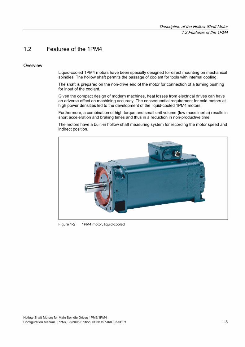
Overview Liquid-cooled 1PM4 motors have been specially designed for direct mounting on mechanical spindles. The hollow shaft permits the passage of coolant for tools with internal cooling.
The shaft is prepared on the non-drive end of the motor for connection of a turning bushing for input of the coolant.
Given the compact design of modern machines, heat losses from electrical drives can have an adverse effect on machining accuracy. The consequential requirement for cold motors at high power densities led to the development of the liquid-cooled 1PM4 motors.
Furthermore, a combination of high torque and small unit volume (low mass inertia) results in short acceleration and braking times and thus in a reduction in non-productive time.
The motors have a built-in hollow shaft measuring system for recording the motor speed and indirect position.
Figure 1-2 1PM4 motor, liquid-cooled
Hollow-Shaft Motors for Main Spindle Drives 1PM6/1PM4 Configuration Manual, (PPM), 08/2005 Edition, 6SN1197-0AD03-0BP1 1-3
Description of the Hollow-Shaft Motor 1.2 Features of the 1PM4
Benefits • Hollow shaft for passage of coolant with direct spindle mounting
• Maximum speed up to 12000 RPM (18000 RPM for the version for increased maximum speed, option L37)
• Full rated torque is continually available - even at standstill
• Cooled flange to prevent thermal stressing of the mechanical power train
• Low noise level
• High rotational accuracy
• Short ramp-up and braking times
Applications • Compact machining centers
• Directly driven tools with internal cooling
• Special machines
Hollow-Shaft Motors for Main Spindle Drives 1PM6/1PM4 1-4 Configuration Manual, (PPM), 08/2005 Edition, 6SN1197-0AD03-0BP1
Description of the Hollow-Shaft Motor 1.3 Technical design, 1PM6 and 1PM4
1.3 Technical design, 1PM6 and 1PM4
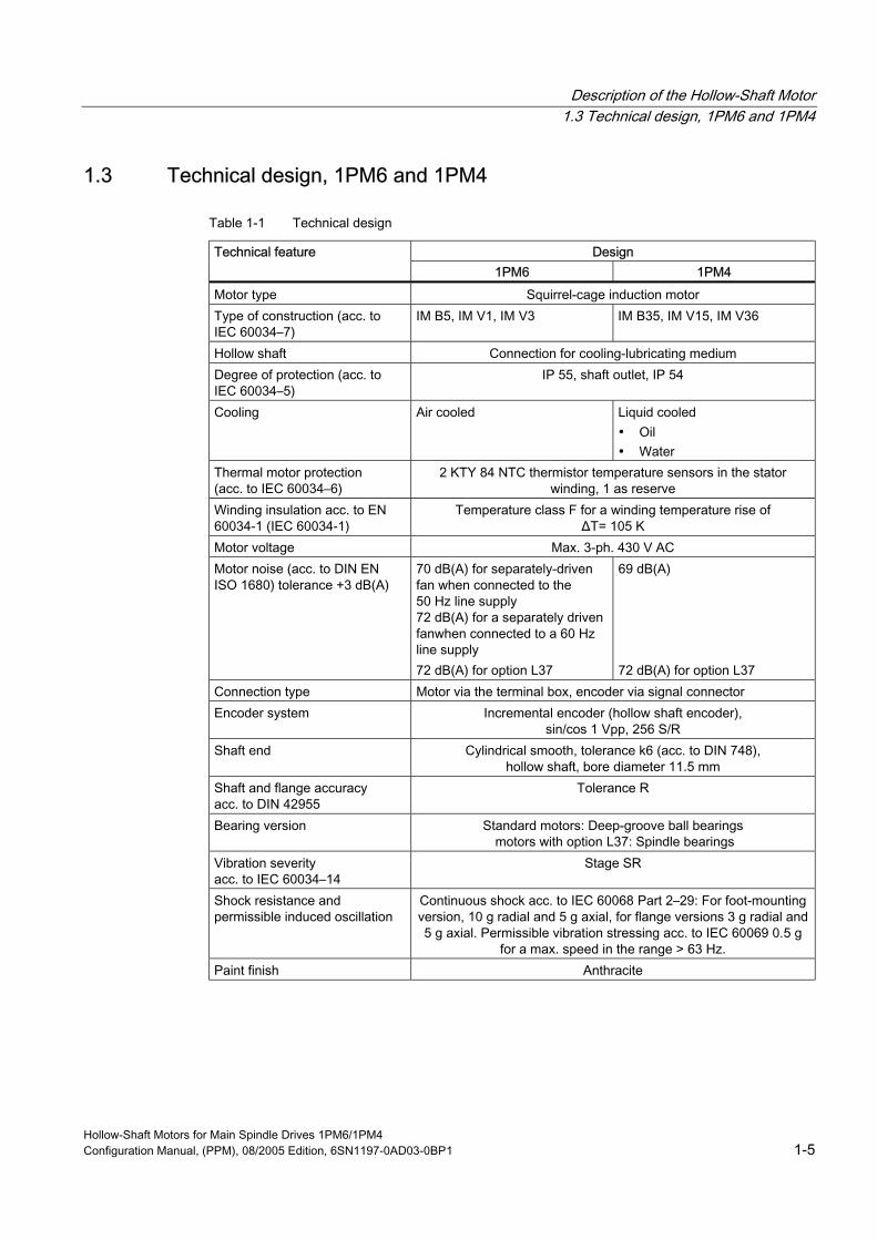
Table 1-1 Technical design
Design Technical feature 1PM6 1PM4
Motor type Squirrel-cage induction motor Type of construction (acc. to IEC 60034–7)
IM B5, IM V1, IM V3 IM B35, IM V15, IM V36
Hollow shaft Connection for cooling-lubricating medium Degree of protection (acc. to IEC 60034–5)
IP 55, shaft outlet, IP 54
Cooling Air cooled Liquid cooled • Oil • Water
Thermal motor protection (acc. to IEC 60034–6)
2 KTY 84 NTC thermistor temperature sensors in the stator winding, 1 as reserve
Winding insulation acc. to EN 60034-1 (IEC 60034-1)
Temperature class F for a winding temperature rise of ΔT= 105 K
Motor voltage Max. 3-ph. 430 V AC Motor noise (acc. to DIN EN 70 dB(A) for separately-driven
fan when connected to the 50 Hz line supply
fanwhen connected to a 60 Hz line supply 72 dB(A) for option L37
69 dB(A) 72 dB(A) for option L37
Connection type Motor via the terminal box, encoder via signal connector Encoder system Incremental encoder (hollow shaft encoder),
sin/cos 1 Vpp, 256 S/R Shaft end Cylindrical smooth, tolerance k6 (acc. to DIN 748),
Shaft and flange accuracy acc. to DIN 42955
Tolerance R
Bearing version Standard motors: Deep-groove ball bearings
Vibration severity acc. to IEC 60034–14
Stage SR
Shock resistance and permissible induced oscillation
Continuous shock acc. to IEC 60068 Part 2–29: For foot-mounting version, 10 g radial and 5 g axial, for flange versions 3 g radial and 5 g axial. Permissible vibration stressing acc. to IEC 60069 0.5 g
for a max. speed in the range > 63 Hz. Paint finish Anthracite
ISO 1680) tolerance +3 dB(A)
72 dB(A) for a separately driven
hollow shaft, bore diameter 11.5 mm
motors with option L37: Spindle bearings
Hollow-Shaft Motors for Main Spindle Drives 1PM6/1PM4 Configuration Manual, (PPM), 08/2005 Edition, 6SN1197-0AD03-0BP1 1-5
Description of the Hollow-Shaft Motor 1.4 Technical data
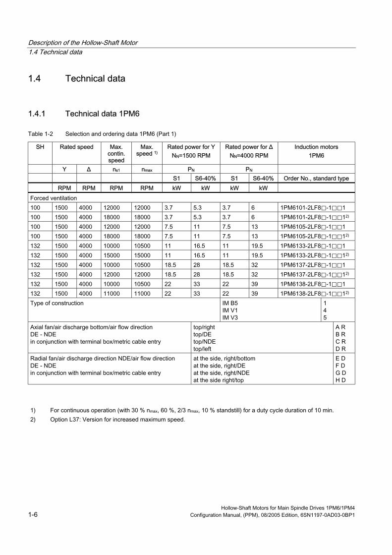
1.4 Technical data
1.4.1 Technical data 1PM6
Table 1-2 Selection and ordering data 1PM6 (Part 1)
SH Rated speed Max. contin. speed
Max.
Rated power for Y NN=1500 RPM
Rated power for Δ NN=4000 RPM
Induction motors 1PM6
Y Δ ns1 n PN PN S1 S6-40% S1 S6-40% Order No., standard type RPM RPM RPM RPM kW kW kW kW Forced ventilation 100 1500 4000 12000 12000 3.7 5.3 3.7 6 1PM6101-2LF8⃞-1⃞⃞1 100 1500 4000 18000 18000 3.7 5.3 3.7 6 1PM6101-2LF8⃞-1⃞⃞12) 100 1500 4000 12000 12000 7.5 11 7.5 13 1PM6105-2LF8⃞-1⃞⃞1 100 1500 4000 18000 18000 7.5 11 7.5 13 1PM6105-2LF8⃞-1⃞⃞12) 132 1500 4000 10000 10500 11 16.5 11 19.5 1PM6133-2LF8⃞-1⃞⃞1 132 1500 4000 15000 15000 11 16.5 11 19.5 1PM6133-2LF8⃞-1⃞⃞12) 132 1500 4000 10000 10500 18.5 28 18.5 32 1PM6137-2LF8⃞-1⃞⃞1 132 1500 4000 12000 12000 18.5 28 18.5 32 1PM6137-2LF8⃞-1⃞⃞12) 132 1500 4000 10000 10500 22 33 22 39 1PM6138-2LF8⃞-1⃞⃞1 132 1500 4000 11000 11000 22 33 22 39 1PM6138-2LF8⃞-1⃞⃞12) Type of construction IM B5
IM V1 IM V3
1 4 5
Axial fan/air discharge bottom/air flow direction DE - NDE in conjunction with terminal box/metric cable entry
top/right top/DE top/NDE top/left
A R B R C R D R
Radial fan/air discharge direction NDE/air flow direction DE - NDE in conjunction with terminal box/metric cable entry
at the side, right/bottom at the side, right/DE at the side, right/NDE at the side right/top
E D F D G D
speed 1)
max
H D
1) For continuous operation (with 30 % nmax, 60 %, 2/3 nmax, 10 % standstill) for a duty cycle duration of 10 min. 2) Option L37: Version for increased maximum speed.
Hollow-Shaft Motors for Main Spindle Drives 1PM6/1PM4 1-6 Configuration Manual, (PPM), 08/2005 Edition, 6SN1197-0AD03-0BP1
Description of the Hollow-Shaft Motor 1.4 Technical data
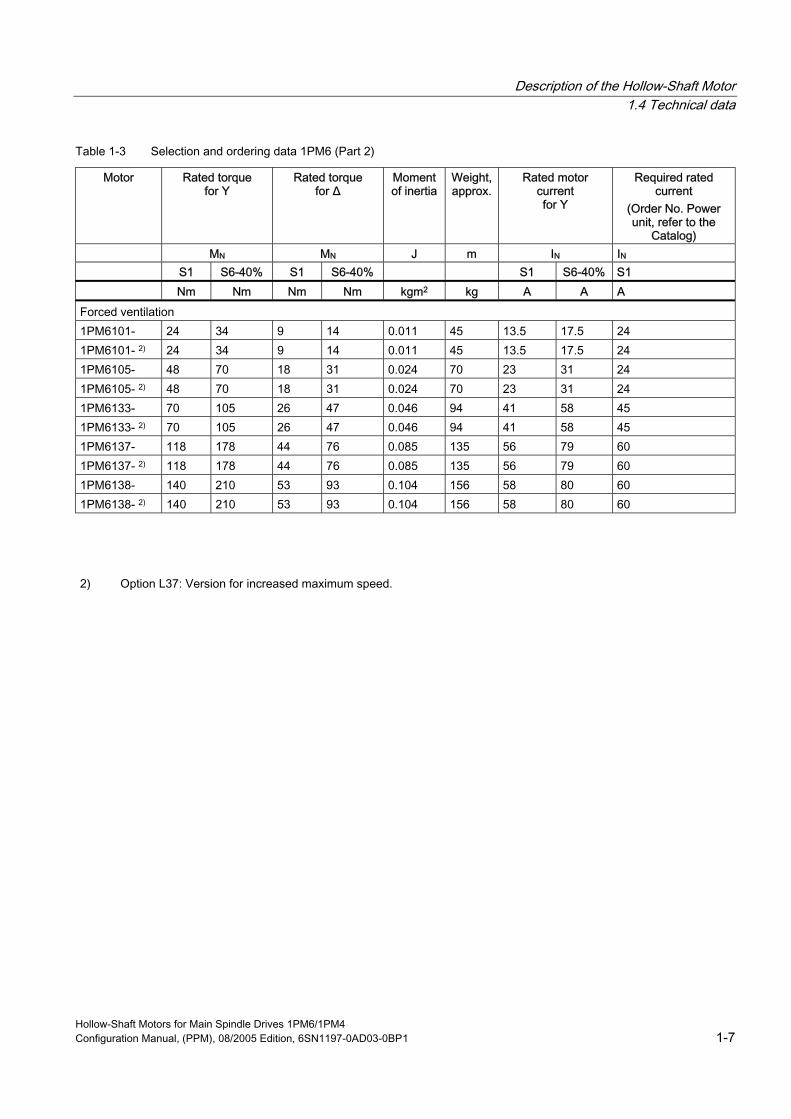
Table 1-3 Selection and ordering data 1PM6 (Part 2)
Motor Rated torque for Y
Rated torque for Δ
Moment of inertia
Weight, approx.
Rated motor current for Y
Required rated current
(Order No. Power unit, refer to the
Catalog) MN MN J m IN IN S1 S6-40% S1 S6-40% S1 S6-40% S1 Nm Nm Nm Nm kgm2 kg A A A Forced ventilation 1PM6101- 24 34 9 14 0.011 45 13.5 17.5 24 1PM6101- 2) 24 34 9 14 0.011 45 13.5 17.5 24 1PM6105- 48 70 18 31 0.024 70 23 31 24 1PM6105- 2) 48 70 18 31 0.024 70 23 31 24 1PM6133- 70 105 26 47 0.046 94 41 58 45 1PM6133- 2) 70 105 26 47 0.046 94 41 58 45 1PM6137- 118 178 44 76 0.085 135 56 79 60 1PM6137- 2) 118 178 44 76 0.085 135 56 79 60 1PM6138- 140 210 53 93 0.104 156 58 80 60 1PM6138- 2) 140 210 53 93 0.104 156 58 80 60
2) Option L37: Version for increased maximum speed.
Hollow-Shaft Motors for Main Spindle Drives 1PM6/1PM4 Configuration Manual, (PPM), 08/2005 Edition, 6SN1197-0AD03-0BP1 1-7
Description of the Hollow-Shaft Motor 1.4 Technical data
1.4.2 Technical data 1PM4
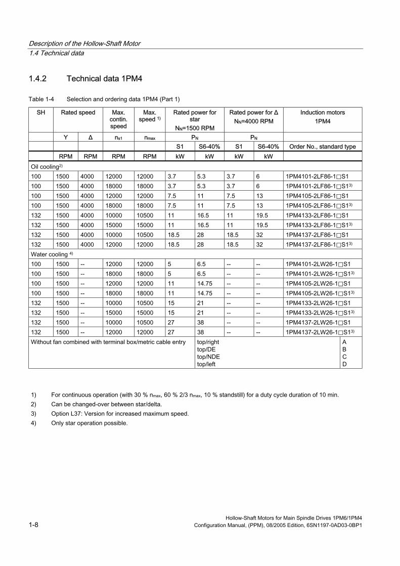
Table 1-4 Selection and ordering data 1PM4 (Part 1)
SH Rated speed Max. contin. speed
Max.
Rated power for star
NN=1500 RPM
Rated power for Δ NN=4000 RPM
Induction motors 1PM4
Y Δ ns1 n PN PN S1 S6-40% S1 S6-40% Order No., standard type RPM RPM RPM RPM kW kW kW kW Oil cooling2) 100 1500 4000 12000 12000 3.7 5.3 3.7 6 1PM4101-2LF86-1⃞S1 100 1500 4000 18000 18000 3.7 5.3 3.7 6 1PM4101-2LF86-1⃞S13) 100 1500 4000 12000 12000 7.5 11 7.5 13 1PM4105-2LF86-1⃞S1 100 1500 4000 18000 18000 7.5 11 7.5 13 1PM4105-2LF86-1⃞S13) 132 1500 4000 10000 10500 11 16.5 11 19.5 1PM4133-2LF86-1⃞S1 132 1500 4000 15000 15000 11 16.5 11 19.5 1PM4133-2LF86-1⃞S13) 132 1500 4000 10000 10500 18.5 28 18.5 32 1PM4137-2LF86-1⃞S1 132 1500 4000 12000 12000 18.5 28 18.5 32 1PM4137-2LF86-1⃞S13) Water cooling 4) 100 1500 -- 12000 12000 5 6.5 -- -- 1PM4101-2LW26-1⃞S1 100 1500 -- 18000 18000 5 6.5 -- -- 1PM4101-2LW26-1⃞S13) 100 1500 -- 12000 12000 11 14.75 -- -- 1PM4105-2LW26-1⃞S1 100 1500 -- 18000 18000 11 14.75 -- -- 1PM4105-2LW26-1⃞S13) 132 1500 -- 10000 10500 15 21 -- -- 1PM4133-2LW26-1⃞S1 132 1500 -- 15000 15000 15 21 -- -- 1PM4133-2LW26-1⃞S13) 132 1500 -- 10000 10500 27 38 -- -- 1PM4137-2LW26-1⃞S1 132 1500 -- 12000 12000 27 38 -- -- 1PM4137-2LW26-1⃞S13) Without fan combined with terminal box/metric cable entry top/right
top/DE top/NDE top/left
A B C D
speed 1)
max
1) For continuous operation (with 30 % nmax, 60 % 2/3 nmax, 10 % standstill) for a duty cycle duration of 10 min. 2) Can be changed-over between star/delta. 3) Option L37: Version for increased maximum speed. 4) Only star operation possible.
Hollow-Shaft Motors for Main Spindle Drives 1PM6/1PM4 1-8 Configuration Manual, (PPM), 08/2005 Edition, 6SN1197-0AD03-0BP1

Description of the Hollow-Shaft Motor 1.4 Technical data
Table 1-5 Selection and ordering data 1PM4 (Part 2)
Motor Rated torque for Y
Rated torque for Δ
Moment of inertia
Weight, approx.
Rated motor current for Y
Required rated current
(Order No. Power unit, refer to the
Catalog) MN MN J m IN IN S1 S6-40% S1 S6-40% S1 S6-40% S1 Nm Nm Nm Nm kgm2 kg A A A Oil cooling2) 1PM4101- 24 34 9 14 0.011 42 13.5 17 24 1PM4101- 3) 24 34 9 14 0.011 42 13.5 17 24 1PM4105- 48 70 18 31 0.024 67 23 31 24 1PM4105- 3) 48 70 18 31 0.024 67 23 31 24 1PM4133- 70 105 26 47 0.046 90 41 58 45 1PM4133- 3) 70 105 26 47 0.046 90 41 58 45 1PM4137- 118 178 44 76 0.085 130 56 79 60 1PM4137- 3) 118 178 44 76 0.085 130 56 79 60 Water cooling 4) 1PM4101- 32 41 -- -- 0.011 42 18 22.5 24 1PM4101- 3) 32 41 -- -- 0.011 42 18 22.5 24 1PM4105- 70 94 -- -- 0.024 67 38 47 45 1PM4105- 3) 70 94 -- -- 0.024 67 38 47 45 1PM4133- 95 134 -- -- 0.046 90 55 74 60 1PM4133- 3) 95 134 -- -- 0.046 90 55 74 60 1PM4137- 172 242 -- -- 0.085 130 85 114 85 1PM4137- 3) 172 242 -- -- 0.085 130 85 114 85
2) Can be changed-over between star/delta. 3) Option L37: Version for increased maximum speed. 4) Only star operation possible.
Hollow-Shaft Motors for Main Spindle Drives 1PM6/1PM4 Configuration Manual, (PPM), 08/2005 Edition, 6SN1197-0AD03-0BP1 1-9

Description of the Hollow-Shaft Motor 1.4 Technical data
Hollow-Shaft Motors for Main Spindle Drives 1PM6/1PM4 1-10 Configuration Manual, (PPM), 08/2005 Edition, 6SN1197-0AD03-0BP1

Electrical Data 2 2.1 Definitions
Maximum speed nmax The max. permissible speed nmax is determined from the mechanical design (bearings, short-circuit ring of the squirrel cage etc.).
Notice The maximum speed nmax may not be exceeded.
The speed must be reduced according to the following load duty cycle:
If the maximum continuous speed nS1 is less than the maximum speed nmax, then the motor may not be continuously operated at the maximum speed nmax. In this particular case, the speed must be reduced according to the following load duty cycle if no other load duty cycle is specified:
30 % nmax 60 % 2/3 nmax 10 % Standstill
for a cycle duration of 10 min.
Maximum continuous speed nS1 The maximum permissible speed that is continuously permitted without speed duty cycles.
Speed n2 Maximum speed that can be achieved at the rated power corresponding to the specified operating mode (duty type) according to IEC 60034-1. The specified values apply for regulated infeed units with a regulated (closed-loop controlled) DC link voltage of 600 V DC.
Maximum torque Mmax Torque that is briefly available for dynamic operations (e.g. accelerating). Mmax = 2 ∙ MN
Hollow-Shaft Motors for Main Spindle Drives 1PM6/1PM4 Configuration Manual, (PPM), 08/2005 Edition, 6SN1197-0AD03-0BP1 2-1

Electrical Data 2.1 Definitions
Max. current Imax It involves the current (rms phase value) that can briefly flow for dynamic operations (e.g. when accelerating) without damaging the motor.
Rated torque MN The rated torque is the torque that is mechanically available at the shaft that can be thermally provided corresponding to the specified operating mode (duty type) according to IEC 60034-1.
Rated speed nN It involves the speed for which the rated power and the rated torque are defined corresponding to the specified operating mode (duty type) according to IEC 60034-1.
Rated current IN It involves the current (rms phase value) that flows at the rated speed and rated torque and can be thermally provided according to the specified operating mode (duty type) according to IEC 60034-1.
Rated voltage VN It involves the voltage between two motor phases for which the rated data (rated power, rated speed, ...) are defined. The rated voltage is defined, taking into account magnetic (iron saturation) and thermal perspectives.
Rated frequency fN It involves the frequency that is necessary to achieve the rated data (rated power, rated speed, rated voltage, .. ).
Rated power PN The rated power is the power that is mechanically available at the shaft that can be thermally provided corresponding to the specified operating mode (duty type) according to IEC 60034-1.
No-load current Iμ This involves the current (rms phase current), that is required in order to operate the motor under no-load conditions at rated speed without load torque. The no-load current defines the motor magnetization in the base speed range (low speed at the start of field weakening).
S1 duty (continuous operation) Operation with a constant load the duration of which is sufficient so that the machine goes into a thermal steady-state condition.
Hollow-Shaft Motors for Main Spindle Drives 1PM6/1PM4 2-2 Configuration Manual, (PPM), 08/2005 Edition, 6SN1197-0AD03-0BP1
Electrical Data 2.2 Mode of operation and power characteristics
S6 duty (intermittent load) S6 duty is operation with comprises a sequence of similar load duty cycles; each of these load duty cycles comprises a time with constant motor load and a no-load time. If not otherwise specified, then the power-on time refers to a load duty cycle of 10 min.
e.g. S6 - 40 %: 4 min load 6 min no-load time
Thermal time constant Tth The thermal time constant defines the temperature rise of the motor winding when the motor load is suddenly increased (step increase) up to the permissible S1 torque. After Tth, the motor has reached 63 % of its S1 final temperature.
2.2 Mode of operation and power characteristics
Mode of operation A constant torque MN is available from standstill up to the rated operating point.
The constant power range starts at the rated operating point (refer to the P/n diagrams in the Planning Guides of the motor sections).
At higher speeds, i.e. in the constant power range, the maximum available torque Mmax at a specific speed n is approximated according to the following formula:
Induction motors have a high overload capacity in the constant power range. For some induction motors, the overload capacity is reduced in the highest speed range. The precise data can be taken from the motor characteristics in the appropriate Planning Guides of the motor sections.
The motor field remains constant over the base speed range up to the rated operating point of the motor. This is then followed by a wide constant power range.
Hollow-Shaft Motors for Main Spindle Drives 1PM6/1PM4 Configuration Manual, (PPM), 08/2005 Edition, 6SN1197-0AD03-0BP1 2-3
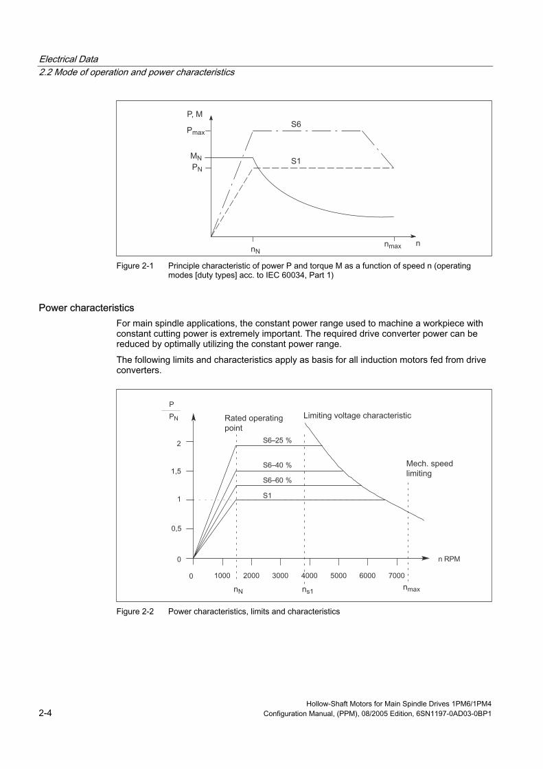
Electrical Data 2.2 Mode of operation and power characteristics
Figure 2-1 Principle characteristic of power P and torque M as a function of speed n (operating
modes [duty types] acc. to IEC 60034, Part 1)
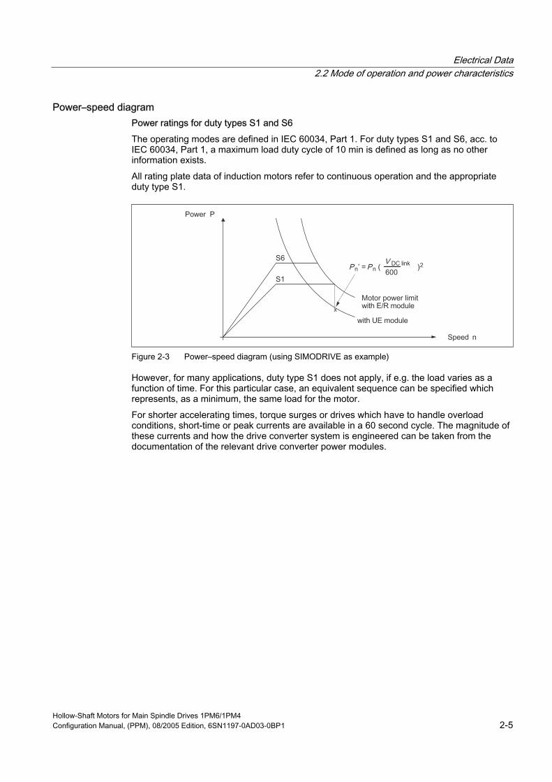
Power characteristics For main spindle applications, the constant power range used to machine a workpiece with constant cutting power is extremely important. The required drive converter power can be reduced by optimally utilizing the constant power range.
The following limits and characteristics apply as basis for all induction motors fed from drive converters.
Figure 2-2 Power characteristics, limits and characteristics
Hollow-Shaft Motors for Main Spindle Drives 1PM6/1PM4 2-4 Configuration Manual, (PPM), 08/2005 Edition, 6SN1197-0AD03-0BP1
Electrical Data 2.2 Mode of operation and power characteristics
Power–speed diagram Power ratings for duty types S1 and S6
The operating modes are defined in IEC 60034, Part 1. For duty types S1 and S6, acc. to IEC 60034, Part 1, a maximum load duty cycle of 10 min is defined as long as no other information exists.
All rating plate data of induction motors refer to continuous operation and the appropriate duty type S1.
Figure 2-3 Power–speed diagram (using SIMODRIVE as example)
However, for many applications, duty type S1 does not apply, if e.g. the load varies as a function of time. For this particular case, an equivalent sequence can be specified which represents, as a minimum, the same load for the motor.
For shorter accelerating times, torque surges or drives which have to handle overload conditions, short-time or peak currents are available in a 60 second cycle. The magnitude of these currents and how the drive converter system is engineered can be taken from the documentation of the relevant drive converter power modules.
Hollow-Shaft Motors for Main Spindle Drives 1PM6/1PM4 Configuration Manual, (PPM), 08/2005 Edition, 6SN1197-0AD03-0BP1 2-5

Electrical Data 2.3 Operation on SIMODRIVE 611
2.3 Operation on SIMODRIVE 611
The drive modules can be operated from both unregulated and regulated supply modules belonging to the SIMODRIVE 611 drive converter system. The engineering and power data of the Catalog refer to operation with the controlled infeed/regenerative feedback modules. This data should be corrected, if required, when operated from unregulated infeed modules.
When operating main spindle and induction drive modules with an uncontrolled (non-regulated) infeed (UI module), then a lower maximum motor output is available in the upper speed range than when using the regulated infeed/regenerative feedback module (refer to the diagram).
As a result of the lower DC link voltage of 490 V, for the UI module, the available continuous output is given by:
If VDC link < 1.5 VN motor then only the following continuous power
is possible at rated speed.
VDC link 490 V for UI module VDC link 600 V for I/R module
These values apply for a 400 V line supply.
For the UI module, it must also be observed that the braking energy, which is fed-in, does not exceed the power rating of the pulsed resistor:
• Infeed module 5 kW 200 W continuous power (regenerative feedback power)
ycle without pre-load condition 10 kW short-time power for 120 ms - once every 10 s load duty c
• Infeed module 10 kW 300 W continuous power (regenerative feedback power)
ycle without pre-load condition 25 kW short-time power for 120 ms - once every 10 s load duty c
• Infeed module 28 kW max. 2 x 300 W continuous power
d duty cycle without pre-load condition or or max. 2 x 1.5 kW continuous power
ad duty cycle without pre-load condition For higher regenerative feedback powers, a separate pulsed resistor module must be provided or the regenerative feedback power reduced by configuring longer braking times.
max. 2 x 25 kW short-time power for 120 ms, once every 10 s loa
max. 2 x 25 kW short-time power for 12 ms once for each 10 s lo
Hollow-Shaft Motors for Main Spindle Drives 1PM6/1PM4 2-6 Configuration Manual, (PPM), 08/2005 Edition, 6SN1197-0AD03-0BP1

Electrical Data 2.4 Motor drive converter assignment (power unit)
2.4 Motor drive converter assignment (power unit) If the rated drive converter current exceeds the rated motor current, then the thermal characteristic (S1) of the motor determines the continuous power of the combination.
Result: The drive converter is therefore not fully utilized.
In the inverse case, the rated drive converter current defines the available continuous power.
Result: The motor isn't thermally fully utilized.
If the drive system is operated using load duty cycles, then the motor must be selected so that the RMS current values do not exceed the permissible S1 value of the motor.
The following generally applies:
If a range is defined by two limit values or characteristics, then the lower limit defines the usable range.
2.5 Motor limits
The speed and power of induction motors are limited for thermal and mechanical reasons1). 1) Stress on the shaft end, bearing stress
Thermal limiting The characteristics for continuous duty S1 and intermittent operation S6-60 %, S6-40 % and S6-25 % describe the permissible power values for an ambient temperature of up to 40 °C. A winding temperature rise of approx. 105 K can occur.
Mechanical limiting It is not permissible that the mechanical limit speed is exceeded. If this speed is exceeded, then this can result in damage to the bearings, short-circuit end rings, press fits etc. It should be ensured that higher speeds are not possible by appropriately designing the control or by activating the speed monitoring in the drive converter.
Hollow-Shaft Motors for Main Spindle Drives 1PM6/1PM4 Configuration Manual, (PPM), 08/2005 Edition, 6SN1197-0AD03-0BP1 2-7
Electrical Data 2.6 Connection system
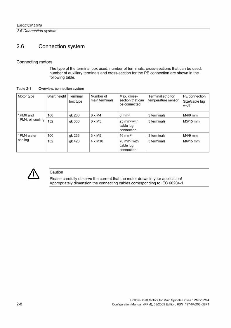
2.6 Connection system
Connecting motors The type of the terminal box used, number of terminals, cross-sections that can be used, number of auxiliary terminals and cross-section for the PE connection are shown in the following table.
Table 2-1 Overview, connection system
Motor type Shaft height Terminal box type
Number of main terminals
Max. cross-section that can be connected
Terminal strip for temperature sensor
PE connection Size/cable lug width
100 gk 230 6 x M4 6 mm2 3 terminals M4/9 mm 1PM6 and 1PM4, oil cooling 132 gk 330 6 x M5 25 mm2 with
cable lug connection
3 terminals M5/15 mm
100 gk 233 3 x M5 16 mm2 3 terminals M4/9 mm 1PM4 water cooling 132 gk 423 4 x M10 70 mm2 with
cable lug connection
3 terminals M6/15 mm
Caution Please carefully observe the current that the motor draws in your application! Appropriately dimension the connecting cables corresponding to IEC 60204-1.
Hollow-Shaft Motors for Main Spindle Drives 1PM6/1PM4 2-8 Configuration Manual, (PPM), 08/2005 Edition, 6SN1197-0AD03-0BP1

Electrical Data 2.6 Connection system
2.6.1 Star/delta circuit configuration The star/delta circuit configuration is implemented using an external contactor circuit or as permanent setting (configuration) in the terminal box.
Figure 2-4 Permanent star and delta circuit configuration in the terminal box using the appropriate
jumpers (these are provided in the terminal box)
Note Water-cooled 1PM4 motors are only operated in the star circuit configuration. These motors cannot be changed-over to a delta circuit configuration.
Hollow-Shaft Motors for Main Spindle Drives 1PM6/1PM4 Configuration Manual, (PPM), 08/2005 Edition, 6SN1197-0AD03-0BP1 2-9

Electrical Data 2.6 Connection system
2.6.2 Power cable The power cables for the 1PM4 and 1PM6 motors are selected according to the rated motor current IN at +40°C according to the table.
Figure 2-5 Power cable
Cross-sections When connecting at the terminal board
• the connecting cables must be dimensioned according to the rated current and
• the size of the cable lugs must be selected corresponding to the dimensions of the terminal studs
Table 2-2 Current load capability acc. to IEC 60204-1 for PVC insulated cables with copper conductors for an ambient temperature of +40°C and routing type C (cables and conductors routed along walls/panels and in cable ducts).
Irms at +40°C [A] Required cross-section [mm2]
Irms at +40°C [A] Required cross-section [mm2]
15.2 1.5 84 25 21 2.5 104 35 28 4 123 50 36 6 155 70 50 10 192 95 66 16 221 120
Note: Correction factors with reference to the ambient temperature and routing type are specified in IEC 60204-1.
Hollow-Shaft Motors for Main Spindle Drives 1PM6/1PM4 2-10 Configuration Manual, (PPM), 08/2005 Edition, 6SN1197-0AD03-0BP1
Electrical Data 2.6 Connection system
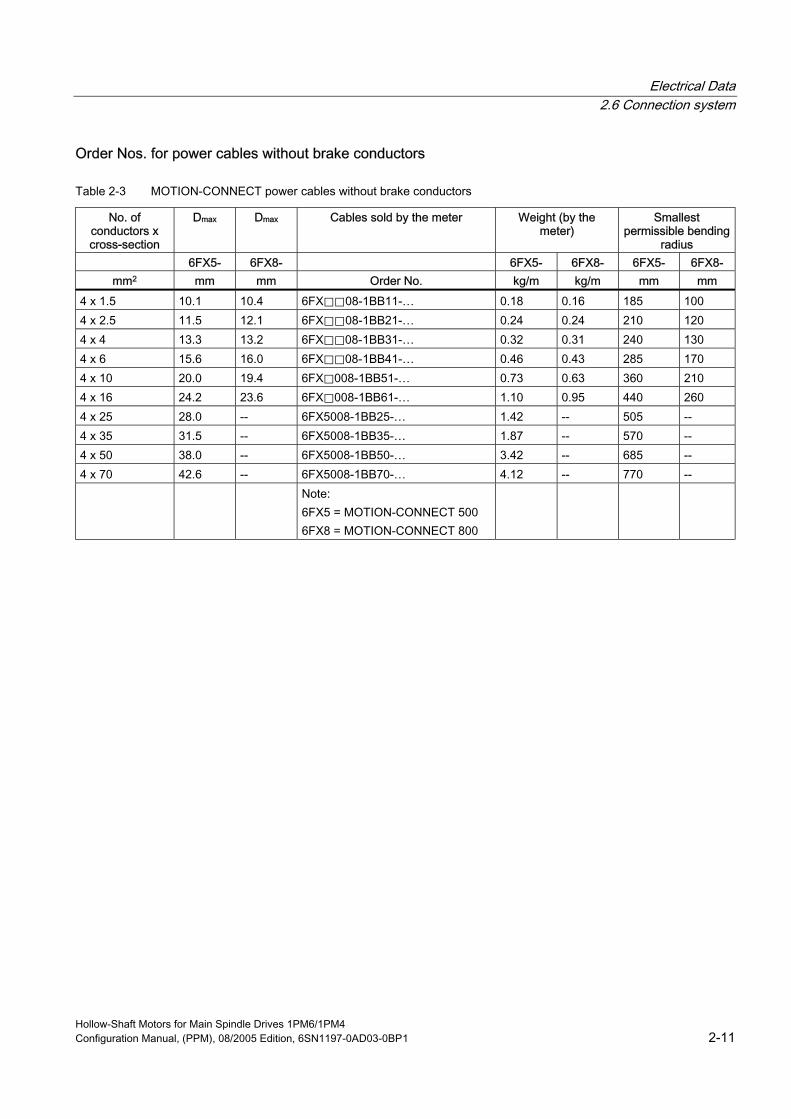
Order Nos. for power cables without brake conductors
Table 2-3 MOTION-CONNECT power cables without brake conductors
No. of conductors x cross-section
Dmax D Cables sold by the meter Weight (by the meter)
Smallest permissible bending
radius 6FX5- 6FX8- 6FX5- 6FX8- 6FX5- 6FX8-
mm2 mm mm Order No. kg/m kg/m mm mm 4 x 1.5 10.1 10.4 6FX⃞⃞08-1BB11-… 0.18 0.16 185 100 4 x 2.5 11.5 12.1 6FX⃞⃞08-1BB21-… 0.24 0.24 210 120 4 x 4 13.3 13.2 6FX⃞⃞08-1BB31-… 0.32 0.31 240 130 4 x 6 15.6 16.0 6FX⃞⃞08-1BB41-… 0.46 0.43 285 170 4 x 10 20.0 19.4 6FX⃞008-1BB51-… 0.73 0.63 360 210 4 x 16 24.2 23.6 6FX⃞008-1BB61-… 1.10 0.95 440 260 4 x 25 28.0 -- 6FX5008-1BB25-… 1.42 -- 505 -- 4 x 35 31.5 -- 6FX5008-1BB35-… 1.87 -- 570 -- 4 x 50 38.0 -- 6FX5008-1BB50-… 3.42 -- 685 -- 4 x 70 42.6 -- 6FX5008-1BB70-… 4.12 -- 770 -- Note:
6FX5 = MOTION-CONNECT 500 6FX8 = MOTION-CONNECT 800
max
Hollow-Shaft Motors for Main Spindle Drives 1PM6/1PM4 Configuration Manual, (PPM), 08/2005 Edition, 6SN1197-0AD03-0BP1 2-11
Electrical Data 2.6 Connection system
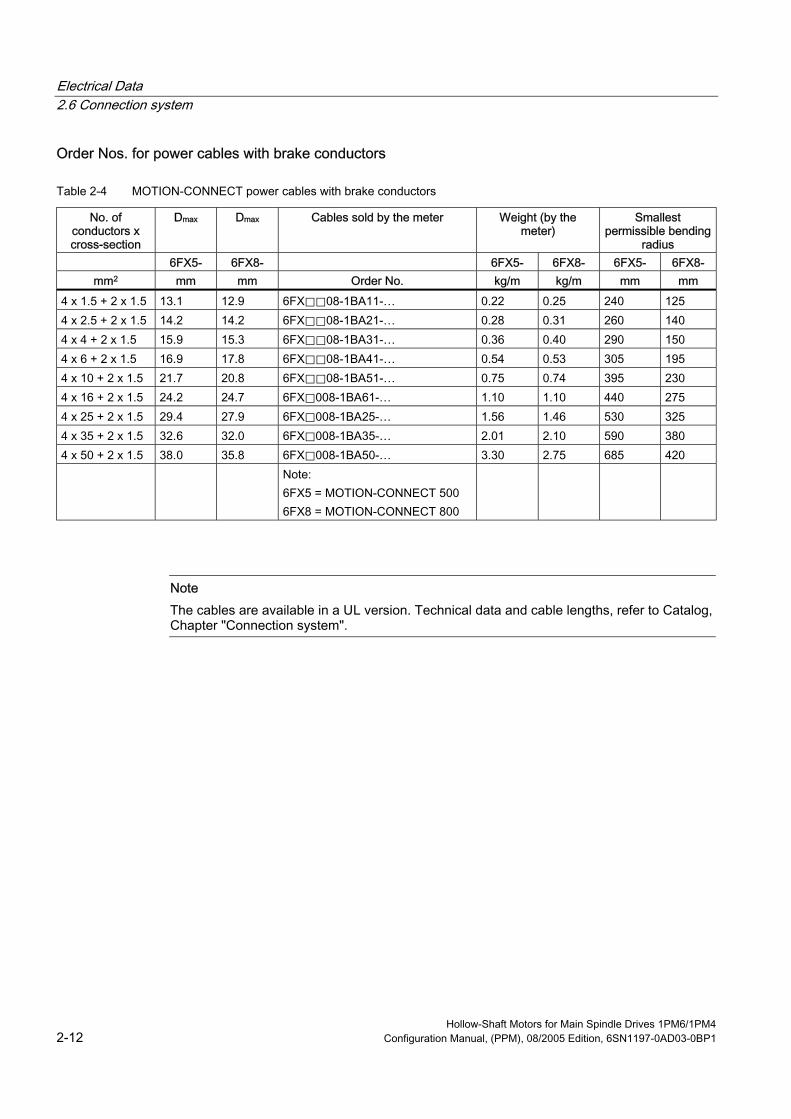
Order Nos. for power cables with brake conductors
Table 2-4 MOTION-CONNECT power cables with brake conductors
No. of conductors x cross-section
Dmax D Cables sold by the meter Weight (by the meter)
Smallest permissible bending
radius 6FX5- 6FX8- 6FX5- 6FX8- 6FX5- 6FX8-
mm2 mm mm Order No. kg/m kg/m mm mm 4 x 1.5 + 2 x 1.5 13.1 12.9 6FX⃞⃞08-1BA11-… 0.22 0.25 240 125 4 x 2.5 + 2 x 1.5 14.2 14.2 6FX⃞⃞08-1BA21-… 0.28 0.31 260 140 4 x 4 + 2 x 1.5 15.9 15.3 6FX⃞⃞08-1BA31-… 0.36 0.40 290 150 4 x 6 + 2 x 1.5 16.9 17.8 6FX⃞⃞08-1BA41-… 0.54 0.53 305 195 4 x 10 + 2 x 1.5 21.7 20.8 6FX⃞⃞08-1BA51-… 0.75 0.74 395 230 4 x 16 + 2 x 1.5 24.2 24.7 6FX⃞008-1BA61-… 1.10 1.10 440 275 4 x 25 + 2 x 1.5 29.4 27.9 6FX⃞008-1BA25-… 1.56 1.46 530 325 4 x 35 + 2 x 1.5 32.6 32.0 6FX⃞008-1BA35-… 2.01 2.10 590 380 4 x 50 + 2 x 1.5 38.0 35.8 6FX⃞008-1BA50-… 3.30 2.75 685 420 Note:
6FX5 = MOTION-CONNECT 500 6FX8 = MOTION-CONNECT 800
max
Note The cables are available in a UL version. Technical data and cable lengths, refer to Catalog, Chapter "Connection system".
Hollow-Shaft Motors for Main Spindle Drives 1PM6/1PM4 2-12 Configuration Manual, (PPM), 08/2005 Edition, 6SN1197-0AD03-0BP1
Electrical Data 2.6 Connection system
2.6.3 Connecting-up information
Note The overall system compatibility is only guaranteed when using shielded power cables.
Shields must be incorporated in the protective grounding concept. Open-circuit or unused, conductors which can be touched, must be connected to protective ground.
Warning Before carrying out any work on the motor, please ensure that it is powered-down and the system is locked-out so that the motor cannot re-start!
Please carefully observe the data on the rating plate and the circuit diagram in the terminal box. Appropriately and adequately dimension the connecting cables.
• Twisted or three-core cables with additional ground conductor should be used as motor feeder cables. The insulation should be removed from the ends of the conductors so that the remaining insulation extends up to the cable lug or terminal.
• The connecting cables should be freely arranged in the terminal box so that the protective conductor has an overlength and the cable conductor insulation cannot be damaged. Connecting cables should be appropriately strain relieved.
• Please ensure that the following minimum air distances are maintained: Supply voltages up to 500 V: Minimum air distance 4.5 mm
• After connecting-up, the following should be checked
– The inside of the terminal box must be clean and free of any cable pieces
– All of the terminal bolts must be tight (tightening torques, refer to the operating instructions)
– The minimum air distances must be maintained
– The cable glands must be reliably sealed
– Unused cable glands must be closed and the plugs must be tightly screwed in place
– All of the sealing surfaces must be in a perfect condition
• The cooling conditions must be carefully observed (refer to Chapter "Cooling")
Hollow-Shaft Motors for Main Spindle Drives 1PM6/1PM4 Configuration Manual, (PPM), 08/2005 Edition, 6SN1197-0AD03-0BP1 2-13

Electrical Data 2.6 Connection system
2.6.4 Motor rating plate 2 motor rating plates are supplied with each motor:
• A rating plate is attached to the motor
• A rating plate is provided in the terminal box
IM B5 IP 55 Th.Cl.F
Made in Germany
SIEMENS3~ Mot. 1PM6133 - 2LF81 - 1ED1 - Z Nr.YF. T531 98765 08 008
V CodeRPMHzcos kWA
222 Y
295
41
41
11
11
0.82
0.68
51.4
133.9
1500
4000
S1
S1
Z: L37 max. 15000 RPMTemp.Sensor KTY 84 - 130 ENCODER Q01 256 S/RCOOLING: AIR
EN 60034
Figure 2-6 Motor rating plate for the 1PM6 series
IM B5 IP 55 Th.Cl.F
Made in Germany
SIEMENS3~ Mot. 1PM4105 - 2LF86 - 1AS1 - Z Nr.YF. T531 98765 09 009
V CodeRPMHzcos kWA
300 Y
375
23
24
7.5
7.5
0.76
0.59
52.2
134.4
1500
4000
S1
S1
Z: L37 max. 18000 RPMTemp.Sensor KTY 84 - 130 ENCODER Q01 256 S/RCOOLING: OIL 6 l/min
EN 60034
Figure 2-7 Motor rating plate for the 1PM4 series
Hollow-Shaft Motors for Main Spindle Drives 1PM6/1PM4 2-14 Configuration Manual, (PPM), 08/2005 Edition, 6SN1197-0AD03-0BP1
Electrical Data 2.7 Thermal motor protection
2.7 Thermal motor protection A KTY84 PTC thermistor is integrated in the stator winding to sense the motor temperature.
Type: KTY 84 Resistance when cold (20 °C): approx. 580 Ω Resistance when hot (100 °C) approx. 1000 Ω Connection: via signal cable Response temperature: Pre-alarm at 120 °C
Shutdown (trip) at 155 °C ± 5 °C
The temperature signal is sensed and evaluated in the drive converter whose closed-loop control takes into account the temperature characteristic of the motor resistances.
The PTC thermistor function is monitored. When a fault occurs, an appropriate signal is output to the control/drive converter. When the motor temperature increases, a signal "Alarm motor overtemperature" is output; this must be externally evaluated. If this signal is not observed, the drive converter shuts down with the appropriate fault signal when the shutdown temperature is exceeded.
The resistance change is proportional to the winding temperature change. For 1PM motors, the temperature characteristic is taken into account in the closed-loop control.
Warning If the user carries-out an additional high-voltage winding test, then the ends of the temperature sensor cables must be short-circuited before the test is carried-out!
If the test voltage is connected to a temperature sensor terminal, then it will be destroyed.
When connecting-up the temperature sensor, carefully ensure that the polarity is correct.
The temperature sensor is designed so that the DIN/EN requirement for protective separation is fulfilled.
Hollow-Shaft Motors for Main Spindle Drives 1PM6/1PM4 Configuration Manual, (PPM), 08/2005 Edition, 6SN1197-0AD03-0BP1 2-15

Electrical Data 2.7 Thermal motor protection
[
I
R [kΩ
Figure 2-8 Resistance characteristic as a function of the KTY 84 thermistor temperature
Hollow-Shaft Motors for Main Spindle Drives 1PM6/1PM4 2-16 Configuration Manual, (PPM), 08/2005 Edition, 6SN1197-0AD03-0BP1

Electrical Data 2.8 Encoders
2.8 Encoders A hollow-shaft encoder is integrated on the non-drive end bearing endshield to sense the speed and rotor position.
Table 2-5 Technical data, sin/cos 1Vpp incremental encoder
Characteristics Incremental encoder sin/cos 1 Vpp (I–256) Resolution, incremental 256 Incremental signals 1 Vpp
The encoder is connected using the flange-mounted socket at the terminal box.
Table 2-6 Connection assignment, 17-pin flange-mounted socket
PIN No. Signal 1 A+
2 A–
3 R+
4 not connected
5 not connected
6 not connected
7 M encoder
8 +1R1 (KTY 84)
9 –1R2 (KTY 84)
10 P encoder
11 B+
12 B –
13 R –
14 not connected
15 0 V sense
16 5 V sense
17 Inner shield
45
6
7
8910
11
1
23
14
17 15
1612
13
When viewing the plug-in side (pins)
Hollow-Shaft Motors for Main Spindle Drives 1PM6/1PM4 Configuration Manual, (PPM), 08/2005 Edition, 6SN1197-0AD03-0BP1 2-17

Electrical Data 2.8 Encoders
Signal cable Pre-assembled cables offer many advantages over cables assembled by customers themselves. In addition to the security of perfect functioning and the high quality, there are also cost benefits.
In order to avoid interference/noise (e.g. due to EMC), and guarantee protective separation, the power cables and signal cables must be separately routed.
Note The maximum cable lengths should be carefully observed.
Figure 2-9 Order designation, signal cable
Hollow-Shaft Motors for Main Spindle Drives 1PM6/1PM4 2-18 Configuration Manual, (PPM), 08/2005 Edition, 6SN1197-0AD03-0BP1

Mechanical Data 3 3.1 Types of construction
The 1PM6 and 1PM4 motor series are available in various types of construction.
Figure 3-1 Types of construction for 1PM6 and 1PM4
For all 1PM4/1PM6 motors, it is possible to provide support at the non-drive end bearing endshield.
Note For 1PM610⃞ with fan, the motor can only be supported using the threads for the lifting lugs located at the side.
3.2 Vibration severity limit values The vibration severity grade limit values are always grade SR in the 1PM6 and 1PM4 series.
Hollow-Shaft Motors for Main Spindle Drives 1PM6/1PM4 Configuration Manual, (PPM), 08/2005 Edition, 6SN1197-0AD03-0BP1 3-1

Mechanical Data 3.2 Vibration severity limit values
Generally, a high cantilever force load capability cannot be realized at the same time as a high operating speed and high vibrational quality.
Figure 3-2 Diagram, vibration severity grade limit values, shaft heights 100 to 132
Hollow-Shaft Motors for Main Spindle Drives 1PM6/1PM4 3-2 Configuration Manual, (PPM), 08/2005 Edition, 6SN1197-0AD03-0BP1
Mechanical Data 3.2 Vibration severity limit values
Requirements placed on the balancing process for mounted components In addition to the balance quality of the motor, the vibration quality of motors with mounted couplings is essentially determined by the balance quality of the mounted component.
If the motor and mounted component are separately balanced before they are assembled, then the process used to balance the coupling must be adapted to the motor balancing type.
The requirements placed on the balancing process for the mounted component is described in the following table.
Table 3-1 Balancing processes, mounted component
Balancing equipment/process step Motor with smooth (no keyway) shaft end
Auxiliary shaft to balance the mounted component
Auxiliary shaft, without key, use, if necessary, a tapered auxiliary shaft,
the required balancing quality of the mounted component
Attaching the mounted component to the auxiliary shaft for balancing
Attach the component as far as possible without any play, e.g. using a light press fit on the tapered auxiliary shaft
Position of the mounted component on the auxiliary shaft for balancing
No special requirements
balancing quality of the auxiliary shaft ≤ 10% of
Natural frequency when mounted When the motor is mounted to the machine/system (flange-mounting is predominantly used) and coupled to the mechanical transmission shaft, vibration characteristics are obtained according to the specific system.
The vibration characteristics depend on the stiffness of the motor foundation. For a rigid coupling, the smooth running characteristics of the drive mechanical transmission are also important. These factors can result in increased vibration values at the motor and for example, for machine tools, in poor machining quality.
Measures to reduce vibration levels Depending on the actual operating conditions, vibration can be reduced by applying the following measures:
• Stiffer motor foundation
• Additionally supporting the motor on the B side (for flange mounting)
• By de-coupling the system from the source of vibration or damping the drive mechanical shaft
Hollow-Shaft Motors for Main Spindle Drives 1PM6/1PM4 Configuration Manual, (PPM), 08/2005 Edition, 6SN1197-0AD03-0BP1 3-3

Mechanical Data 3.3 Bearing design
3.3 Bearing design
3.3.1 Drive output types and bearing versions Bearing version for 1PM⃞ standard: Deep-groove ball bearings
Bearing version for 1PM⃞ with option L37: Spindle bearings
A drive output without any cantilever force is required, e.g. a coupling drive output.
Single-row (race) bearings with deep-groove ball bearings (1) or spindle bearings for option L37
Max. speed and max. continuous speed
Table 3-2 Max. speed and max. continuous speed
Shaft height Standard motors Motors with option L37 Max.
speed [RPM]
Max. continuous speed [RPM]
Max. speed [RPM]
Max. continuous speed [RPM]
1PM⃞101 12000 12000 18000 18000 1PM⃞105 12000 12000 18000 18000 1PM⃞133 10500 10000 15000 15000 1PM⃞137 10500 10000 12000 12000 1PM6138 10500 10000 11000 11000
Hollow-Shaft Motors for Main Spindle Drives 1PM6/1PM4 3-4 Configuration Manual, (PPM), 08/2005 Edition, 6SN1197-0AD03-0BP1
Mechanical Data 3.3 Bearing design
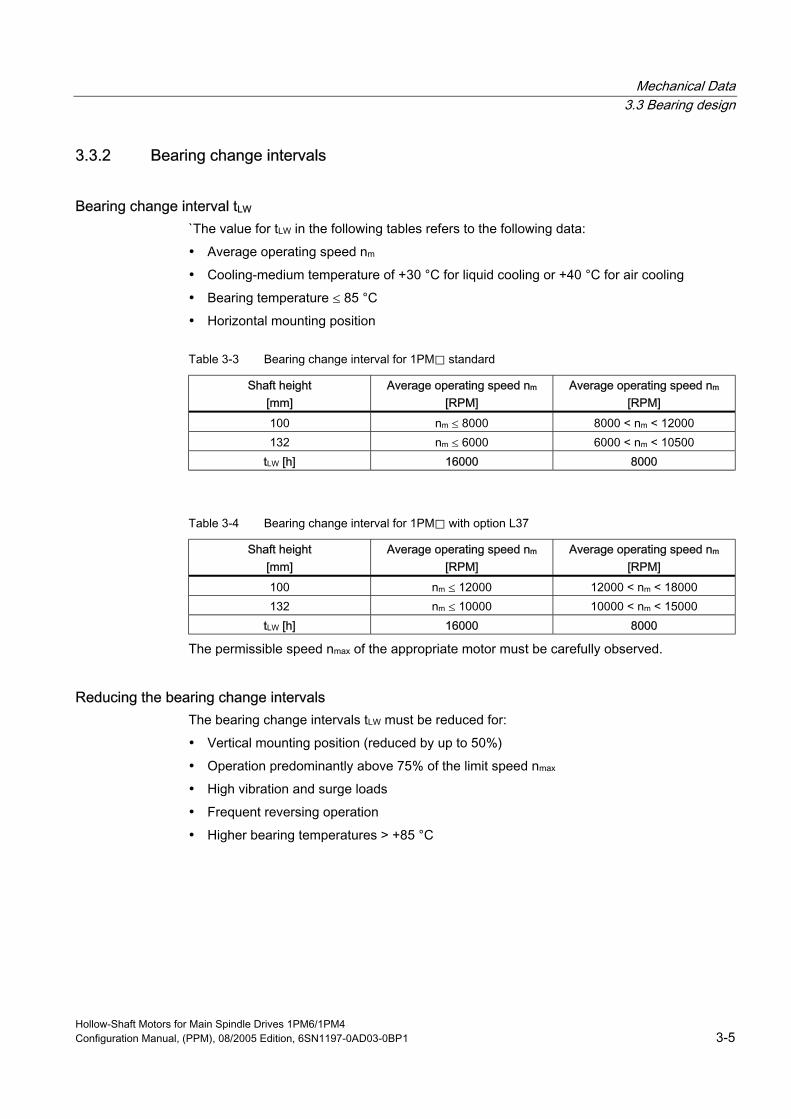
3.3.2 Bearing change intervals
Bearing change interval tLW `The value for tLW in the following tables refers to the following data:
• Average operating speed nm
• Cooling-medium temperature of +30 °C for liquid cooling or +40 °C for air cooling
• Bearing temperature ≤ 85 °C
• Horizontal mounting position
Table 3-3 Bearing change interval for 1PM⃞ standard
Shaft height [mm]
Average operating speed nm [RPM]
Average operating speed nm [RPM]
100 nm ≤ 8000 8000 < nm < 12000 132 nm ≤ 6000 6000 < nm < 10500
tLW [h] 16000 8000
Table 3-4 Bearing change interval for 1PM⃞ with option L37
Shaft height [mm]
Average operating speed nm [RPM]
Average operating speed nm [RPM]
100 nm ≤ 12000 12000 < nm < 18000 132 nm ≤ 10000 10000 < nm < 15000
tLW [h] 16000 8000
The permissible speed nmax of the appropriate motor must be carefully observed.
Reducing the bearing change intervals The bearing change intervals tLW must be reduced for:
• Vertical mounting position (reduced by up to 50%)
• Operation predominantly above 75% of the limit speed nmax
• High vibration and surge loads
• Frequent reversing operation
• Higher bearing temperatures > +85 °C
Hollow-Shaft Motors for Main Spindle Drives 1PM6/1PM4 Configuration Manual, (PPM), 08/2005 Edition, 6SN1197-0AD03-0BP1 3-5
Mechanical Data 3.3 Bearing design
3.3.3 Cantilever and axial forces
Cantilever force In order to guarantee perfect operation, the cantilever force may not exceeded 200 N.
Axial force The axial force acting on the locating bearing comprises the following components:
• Operational axial force
– Axial forces externally acting on the motor
– Axial forces from the cooling-medium pressure of the cooling-lubricating medium fed through the rotary gland
• Force due to pre-loaded bearings
• Possible force due to the rotor weight when the motor is vertically mounted
This results in a maximum axial force that is a function of the direction.
Caution Carefully observe the axial force as a result of the effective hydraulic diameter (surface) of the rotary gland.
urface m2) x p (cooling-medium pressure in N/m2); 1 bar = 105 N/m2
Force F [N] = A (s
For axial forces in the direction of the motor, the spring-loading of the bearings can be overcome so that the rotor moves corresponding to the axial bearing play present (up to 0.2 mm). The permissible axial force FAZ in operation depends on the motor mounting position.
Hollow-Shaft Motors for Main Spindle Drives 1PM6/1PM4 3-6 Configuration Manual, (PPM), 08/2005 Edition, 6SN1197-0AD03-0BP1
Mechanical Data 3.3 Bearing design
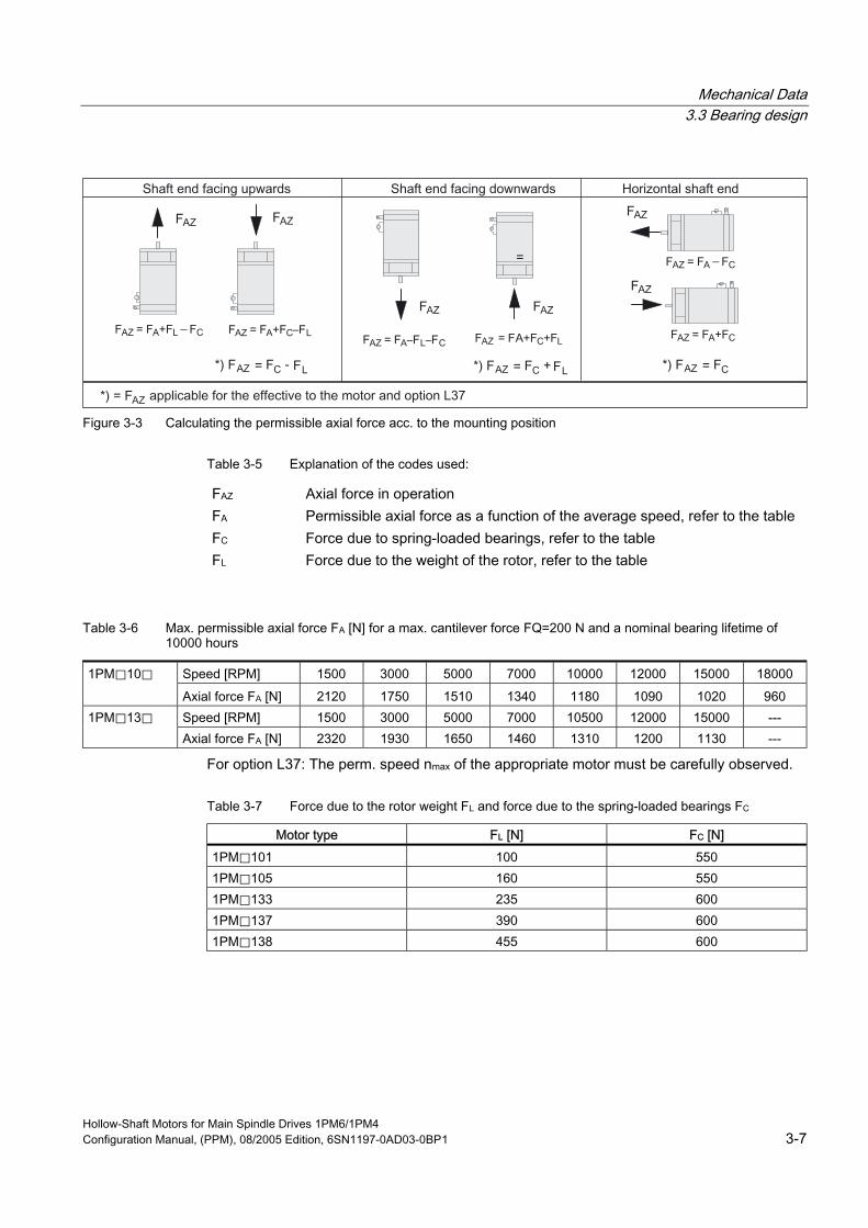
Figure 3-3 Calculating the permissible axial force acc. to the mounting position
Table 3-5 Explanation of the codes used:
FAZ Axial force in operation FA Permissible axial force as a function of the average speed, refer to the table FC Force due to spring-loaded bearings, refer to the table FL Force due to the weight of the rotor, refer to the table
Table 3-6 Max. permissible axial force FA [N] for a max. cantilever force FQ=200 N and a nominal bearing lifetime of 10000 hours
Speed [RPM] 1500 3000 5000 7000 10000 12000 15000 18000 1PM⃞10⃞
Axial force FA [N] 2120 1750 1510 1340 1180 1090 1020 960 Speed [RPM] 1500 3000 5000 7000 10500 12000 15000 --- 1PM⃞13⃞ Axial force FA [N] 2320 1930 1650 1460 1310 1200 1130 ---
For option L37: The perm. speed nmax of the appropriate motor must be carefully observed.
Table 3-7 Force due to the rotor weight FL and force due to the spring-loaded bearings FC
Motor type FL [N] FC [N] 1PM⃞101 100 550 1PM⃞105 160 550 1PM⃞133 235 600 1PM⃞137 390 600 1PM⃞138 455 600
Hollow-Shaft Motors for Main Spindle Drives 1PM6/1PM4 Configuration Manual, (PPM), 08/2005 Edition, 6SN1197-0AD03-0BP1 3-7

Mechanical Data 3.4 Cooling
3.4 Cooling Hollow-shaft motors must be continually cooled independent of the duty type (S1, S6).
Force ventilated (1PM6 series) For air-cooled motors, the cooling ducts, through which the ambient air flows, must be regularly cleaned depending on the degree of pollution at the mounting location. These air ducts can be cleaned, e.g. using dry, oil-free compressed air.
Liquid cooling (1PM4 series) For liquid-cooled motors, the cooling conditions (intake temperature, water flow rate, cooling power) must be maintained.
For the 1PM4 series, either oil or water can be used as cooling medium.
• Oil cooling, refer to the Chapter "Liquid cooling (oil)"
• Water cooling, refer to Chapter "Liquid cooling (water)"
The cooling medium must be pre-cleaned and filtered in order to prevent the cooling circuit from becoming blocked. After filtering, the max. permissible particle size may be 100 μm.
Materials used in the cooling circuits The anti-corrosion additives used should be harmonized with the cooling system manufacturer - i.e. the materials of the motor cooler and the materials of the fittings and cooling medium hoses listed in the table.
Table 3-8 Materials used in the motor cooling circuit
Motor type Bearing end shield Casing Sealing agent 1PM6/1PM4 Gray cast iron AI-profile
DIN EN 12020 Terostat
Notice Non-ferrous metals (e.g. copper or brass pipes) should not be used when water cooling is being used due to the formation of electrolytes. In combination with the motor materials, there is the danger of corrosion.
Hollow-Shaft Motors for Main Spindle Drives 1PM6/1PM4 3-8 Configuration Manual, (PPM), 08/2005 Edition, 6SN1197-0AD03-0BP1
Mechanical Data 3.4 Cooling
Cooling system A cooling system is required for operation. Manufacturers of cooling systems, refer to Catalog NC 60.
3.4.1 Cooling-lubricating medium gland The rotary gland for the cooling-lubricating medium must be mounted at the non-drive end shaft centering (screwed) - refer to the following diagrams.
The rotary gland is mounted carefully following the manufacturer's specifications.
• Gatt (Gesellschaft für Antriebstechnik mbH) Schloßbergstr. 19, D-65201 Wiesbaden URL: www.gat-mbh.de
• DEUBLIN GmbH, Postfach 400133, D-65708 Hofheim URL: www.deublin.com
• Ott-Jakob GmbH&Co Industriestraße 3-7, D-87663 Lengenwang URL: www.ott-jakob.de
For the 1PM6 series with mounted axial fan, when mounting the rotary gland, the fan - together with the adapter - must be removed. A recess/cut-out must be provided in the adapter (intermediate housing) for the cooling-lubricating medium feed. This opening must be clean.
Notice When mounting the rotary gland, it must be carefully ensured that the thread is tightly screwed into the non-drive shaft end so that no cooling medium can leak.
Hollow-Shaft Motors for Main Spindle Drives 1PM6/1PM4 Configuration Manual, (PPM), 08/2005 Edition, 6SN1197-0AD03-0BP1 3-9

Mechanical Data 3.4 Cooling
Figure 3-4 Rotary gland for 1PM6, radial fan
Hollow-Shaft Motors for Main Spindle Drives 1PM6/1PM4 3-10 Configuration Manual, (PPM), 08/2005 Edition, 6SN1197-0AD03-0BP1
Mechanical Data 3.4 Cooling
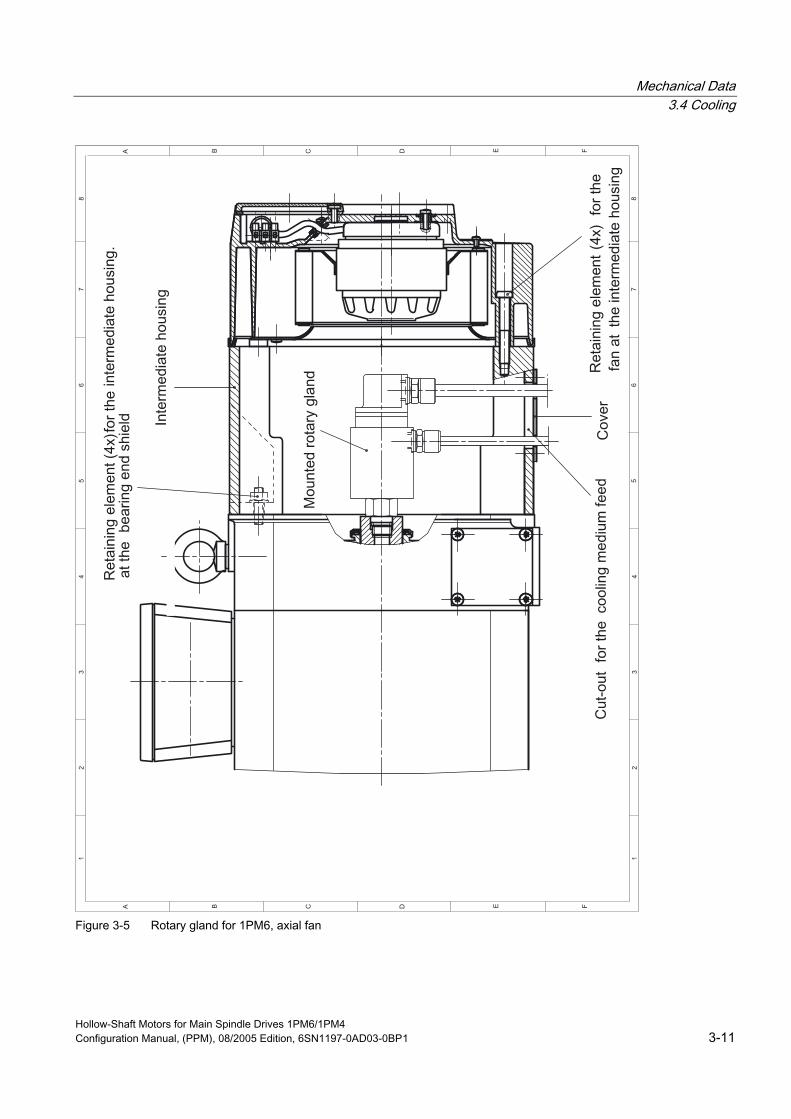
Figure 3-5 Rotary gland for 1PM6, axial fan
Hollow-Shaft Motors for Main Spindle Drives 1PM6/1PM4 Configuration Manual, (PPM), 08/2005 Edition, 6SN1197-0AD03-0BP1 3-11

Mechanical Data 3.4 Cooling
Figure 3-6 1PM6 and 1PM4, shaft end for the radial gland
Hollow-Shaft Motors for Main Spindle Drives 1PM6/1PM4 3-12 Configuration Manual, (PPM), 08/2005 Edition, 6SN1197-0AD03-0BP1
Mechanical Data 3.4 Cooling
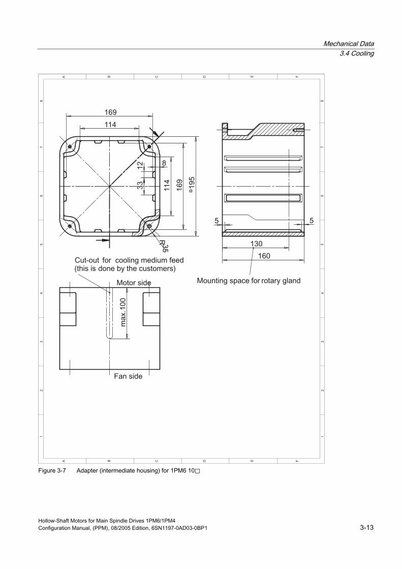
Figure 3-7 Adapter (intermediate housing) for 1PM6 10⃞
Hollow-Shaft Motors for Main Spindle Drives 1PM6/1PM4 Configuration Manual, (PPM), 08/2005 Edition, 6SN1197-0AD03-0BP1 3-13

Mechanical Data 3.4 Cooling
Figure 3-8 Adapter (intermediate housing) for 1PM6 13⃞
Hollow-Shaft Motors for Main Spindle Drives 1PM6/1PM4 3-14 Configuration Manual, (PPM), 08/2005 Edition, 6SN1197-0AD03-0BP1
Mechanical Data 3.4 Cooling
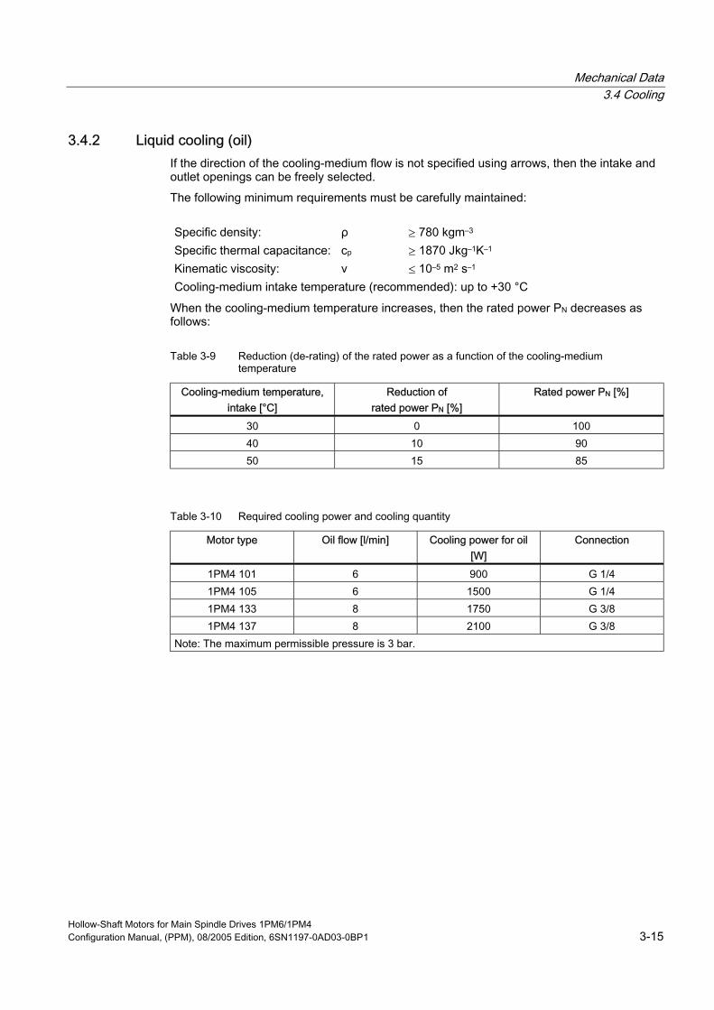
3.4.2 Liquid cooling (oil) If the direction of the cooling-medium flow is not specified using arrows, then the intake and outlet openings can be freely selected.
The following minimum requirements must be carefully maintained:
Specific density: ρ ≥ 780 kgm–3 Specific thermal capacitance: cp ≥ 1870 Jkg–1K–1 Kinematic viscosity: ν ≤ 10–5 m2 s–1 Cooling-medium intake temperature (recommended): up to +30 °C
When the cooling-medium temperature increases, then the rated power PN decreases as follows:
Table 3-9 Reduction (de-rating) of the rated power as a function of the cooling-medium temperature
Cooling-medium temperature, intake [°C]
Reduction of rated power PN [%]
Rated power PN [%]
30 0 100 40 10 90 50 15 85
Table 3-10 Required cooling power and cooling quantity
Motor type Oil flow [l/min] Cooling power for oil [W]
Connection
1PM4 101 6 900 G 1/4 1PM4 105 6 1500 G 1/4 1PM4 133 8 1750 G 3/8 1PM4 137 8 2100 G 3/8
Note: The maximum permissible pressure is 3 bar.
Hollow-Shaft Motors for Main Spindle Drives 1PM6/1PM4 Configuration Manual, (PPM), 08/2005 Edition, 6SN1197-0AD03-0BP1 3-15
Mechanical Data 3.4 Cooling
3.4.3 Liquid cooling (water) If the direction of the cooling-medium flow is not specified using arrows, then the intake and outlet openings can be freely selected.
Cooling medium and anti-corrosion protection An anti-corrosion additive must always be added to the cooling water (e.g. Tyfocor from Tyforop Chemie GmbH). Percentage, max. 25 %.
Note Different anti-corrosion agents should not be mixed.
The cooling water should have the values/parameters:
Chemically neutral, clean, and free of solids Size of particles possibly in the flow of water (if required, use a filter to filter-out these particles):
Max. 100 µm
pH value: 6-7 Chloride: < 50 ppm Conductivity (only water): < 500 mS/cm
Notice If frost can be expected while the system is non-operational, is being transported or is in storage, then a commercially available antifreeze must be added.
The checking and change intervals for the cooling medium should be harmonized with the companies supplying the anti-corrosion agent and the cooling system.
Hollow-Shaft Motors for Main Spindle Drives 1PM6/1PM4 3-16 Configuration Manual, (PPM), 08/2005 Edition, 6SN1197-0AD03-0BP1

Mechanical Data 3.4 Cooling
When using another cooling medium (e.g. oil) de-rating may be required in order that the thermal motor limit is not exceeded. The de-rating can be determined using the following data:
Specific density: ρ [kg/m3] Specific thermal capacitance: cp [J/(kg K)] Intake temperature: tv [°C] Flow quantity: v [l/min]
The enquiry must be sent to the manufacturer's plant (Hotline).
The motor power still does not have to be reduced for oil - water mixtures with less than 10 %.
Manufacturers of chemical additives
Table 3-11 Manufacturers of chemical additives
Company Address Telephone/Internet
Tyforop Chemie GmbH Hellbrookstr. 5a, D–22305 Hamburg
www.tyfo.de
Joh.A. Beckiser Bergstr. 17 D-40699 Erkrath
Tel.: 02104 / 40075
CINCINNATI CIMCOOL Cincinnati Milacron b. v. / Cimcool Division
Postfach 98 NL–3031 AB Vlaardingen
Tel.: 003110 / 4600660
Fuchs Petrolub AG Friesenheimer Strasse 17 D-68169 Mannheim
Tel.: 0621 / 3802–0 www.fuchs–oil.com
Hebro Chemie GmbH Rostocker Straße D-41199 Mönchengladbach
Tel.: 02166 / 6009–0 www.hebro–chemie.de
Clariant Refer to the Internet www.clariant.com Houghton Lubricor GmbH Werkstrasse 26
D-52076 Aachen Tel.: 02408 / 14060
Schilling–Chemie GmbH u. Produktions KG
Steinbeißstr. 20 D-71691 Freiberg
Tel.: 07141 / 7030
Motorex Coolant F Refer to the Internet www.motorex.ch
Wassertechnik GmbH
Note These recommendations involve third-party products which we know to be basically suitable. It goes without saying that similar products from other manufacturers can also be used. Our recommendations should be considered as such. We cannot accept any liability for the quality and properties/features of third-party products.
Hollow-Shaft Motors for Main Spindle Drives 1PM6/1PM4 Configuration Manual, (PPM), 08/2005 Edition, 6SN1197-0AD03-0BP1 3-17

Mechanical Data 3.4 Cooling
Cooling-medium intake temperature, required cooling power Cooling-medium intake temperature (recommended): up to +30 °C
In order to avoid moisture condensation, the cooling-medium intake temperature can, depending on the ambient temperature, be up to 40 °C.
When the cooling-medium temperature increases, then the rated power PN decreases as follows:
Table 3-12 Reduction (de-rating) of the rated power as a function of the cooling-medium temperature (intake)
Cooling medium temperature, intake [°C] Rated power PN [%] 30 100 40 90 50 85
Table 3-13 Required cooling power and cooling quantity
Motor type Cold water flow [l/min]
Cooling power for water [W]
Connection
1PM4 101 6 1400 G 1/4 1PM4 105 6 2600 G 1/4 1PM4 133 8 2750 G 3/8 1PM4 137 8 3300 G 3/8
Note: The maximum permissible pressure is 3 bar.
Hollow-Shaft Motors for Main Spindle Drives 1PM6/1PM4 3-18 Configuration Manual, (PPM), 08/2005 Edition, 6SN1197-0AD03-0BP1
Mechanical Data 3.4 Cooling
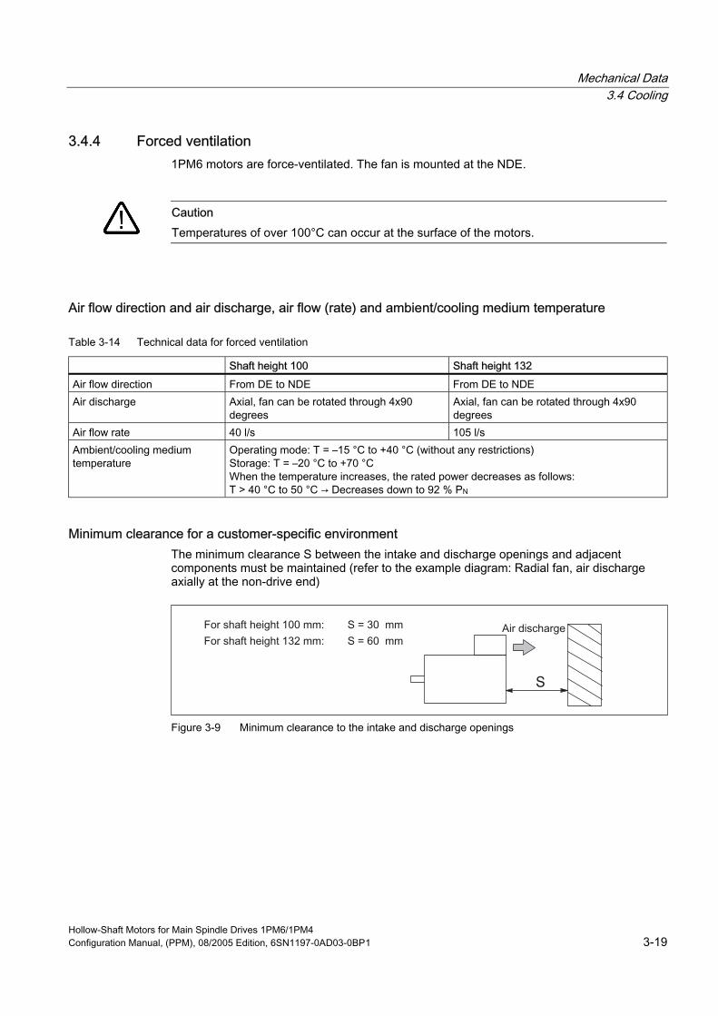
3.4.4 Forced ventilation 1PM6 motors are force-ventilated. The fan is mounted at the NDE.
Caution Temperatures of over 100°C can occur at the surface of the motors.
Air flow direction and air discharge, air flow (rate) and ambient/cooling medium temperature
Table 3-14 Technical data for forced ventilation
Shaft height 100 Shaft height 132
Air flow direction From DE to NDE From DE to NDE Air discharge Axial, fan can be rotated through 4x90
degrees Axial, fan can be rotated through 4x90 degrees
Air flow rate 40 l/s 105 l/s Ambient/cooling medium temperature
Operating mode: T = –15 °C to +40 °C (without any restrictions) Storage: T = –20 °C to +70 °C
he rated power decreases as follows: T > 40 °C to 50 °C → Decreases down to 92 % PN When the temperature increases, t
Minimum clearance for a customer-specific environment The minimum clearance S between the intake and discharge openings and adjacent components must be maintained (refer to the example diagram: Radial fan, air discharge axially at the non-drive end)
Figure 3-9 Minimum clearance to the intake and discharge openings
Hollow-Shaft Motors for Main Spindle Drives 1PM6/1PM4 Configuration Manual, (PPM), 08/2005 Edition, 6SN1197-0AD03-0BP1 3-19

Mechanical Data 3.4 Cooling
Connection values, separately-driven fan and current drain
Table 3-15 Connection values, separately driven fan
Shaft height [mm] Voltage [V] 100 3-ph. 50 Hz 400 V AC (± 10 %)
3-ph. 60 Hz 400 V AC ( ±10 %) 3-ph. 60 Hz 480 V AC (+6% / –10%)
132 3-ph. 50 Hz 400 V AC (± 10 %) 3-ph. 60 Hz 400 V AC ( ±10 %) 3-ph. 60 Hz 480 V AC (+6% / –10%)
Table 3-16 Current consumption
Motor type IN [A], at 400 V, 50 Hz
IN [A], at 480 V, 60 Hz
Current drain Imax [A]
1PM6 10⃞ 0.15 0.15 0.3 1PM6 13⃞ 0.25 0.30 0.36
Recommended connection The connection is established through the terminal box. The fan must be fed through a motor protection circuit-breaker. The direction of rotation of the fan must be carefully checked.
Figure 3-10 Recommended connection
Note The motor protection circuit-breaker should be set to value Imax. of the fan.
Hollow-Shaft Motors for Main Spindle Drives 1PM6/1PM4 3-20 Configuration Manual, (PPM), 08/2005 Edition, 6SN1197-0AD03-0BP1
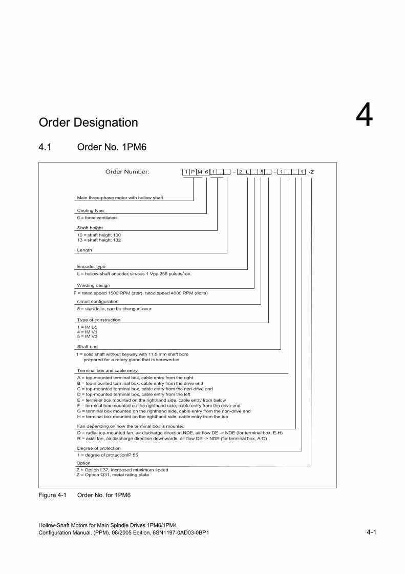
Order Designation 4 4.1 Order No. 1PM6
Figure 4-1 Order No. for 1PM6
Hollow-Shaft Motors for Main Spindle Drives 1PM6/1PM4 Configuration Manual, (PPM), 08/2005 Edition, 6SN1197-0AD03-0BP1 4-1

Order Designation 4.2 Order No. for 1PM4
4.2 Order No. for 1PM4
Figure 4-2 Order No. for 1PM4
Hollow-Shaft Motors for Main Spindle Drives 1PM6/1PM4 4-2 Configuration Manual, (PPM), 08/2005 Edition, 6SN1197-0AD03-0BP1

Order Designation 4.3 Ordering examples for the 1PM4 series
4.3 Ordering examples for the 1PM4 series
1PM4, oil-cooled
Figure 4-3 Order No. for 1PM4, oil-cooled
Hollow-Shaft Motors for Main Spindle Drives 1PM6/1PM4 Configuration Manual, (PPM), 08/2005 Edition, 6SN1197-0AD03-0BP1 4-3

Order Designation 4.3 Ordering examples for the 1PM4 series
1PM4, water-cooled
Figure 4-4 Order No. for 1PM4, water-cooled
Hollow-Shaft Motors for Main Spindle Drives 1PM6/1PM4 4-4 Configuration Manual, (PPM), 08/2005 Edition, 6SN1197-0AD03-0BP1
Technical Data and Characteristics 5 5.1 Power-speed and torque-speed diagrams
Power ratings for duty types S1 and S6 The operating modes (duty types) are defined in IEC 60034, Part 1. A maximum load duty cycle of 10 min. is defined here - the S6 power data in the characteristics are referred to this.
Table 5-1 Explanation of the codes in alphabetical order
Abbreviation Units Description fN Hz Rated frequency Imax A Maximum current IN A Rated current Iμ A No-load current MN Nm Rated torque n2 1/min (rpm) Speed for field weakening with constant power nmax 1/min (rpm) Maximum rotational speed
nN 1/min (rpm) Rated speed PN kW Rated power Tth min Thermal time constant UN V Rated voltage
Hollow-Shaft Motors for Main Spindle Drives 1PM6/1PM4 Configuration Manual, (PPM), 08/2005 Edition, 6SN1197-0AD03-0BP1 5-1
Technical Data and Characteristics 5.1 Power-speed and torque-speed diagrams
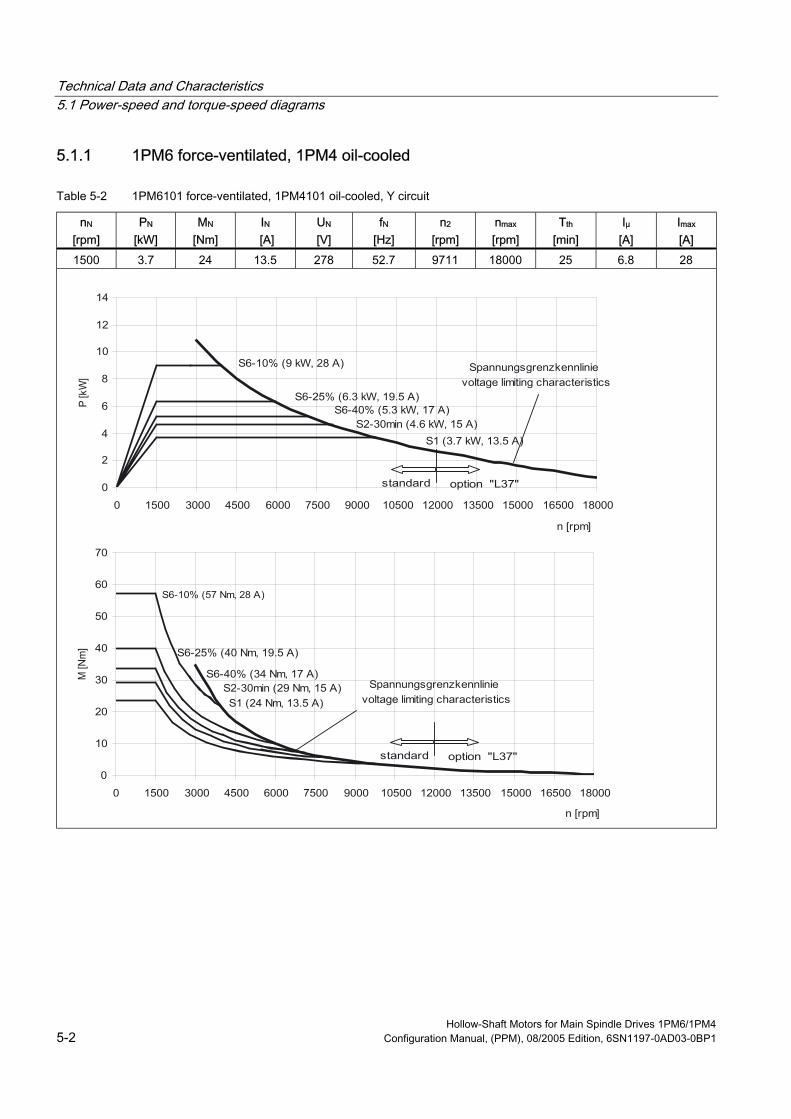
5.1.1 1PM6 force-ventilated, 1PM4 oil-cooled
Table 5-2 1PM6101 force-ventilated, 1PM4101 oil-cooled, Y circuit
nN [rpm]
PN [kW]
MN [Nm]
IN [A]
UN [V]
fN [Hz]
n2 [rpm]
nmax [rpm]
Tth [min]
Iμ [A]
Imax [A]
1500 3.7 24 13.5 278 52.7 9711 18000 25 6.8 28
S6-10% (57 Nm, 28 A)
Hollow-Shaft Motors for Main Spindle Drives 1PM6/1PM4 5-2 Configuration Manual, (PPM), 08/2005 Edition, 6SN1197-0AD03-0BP1

Technical Data and Characteristics 5.1 Power-speed and torque-speed diagrams
Table 5-3 1PM6101 force-ventilated, 1PM4101 oil-cooled, ∆ circuit
nN [rpm]
PN [kW]
MN [Nm]
IN [A]
UN [V]
fN [Hz]
n2 [rpm]
nmax [rpm]
Tth [min]
Iμ [A]
Imax [A]
4000 3.7 9 14 336 134.7 12000 18000 25 9.6 26
Hollow-Shaft Motors for Main Spindle Drives 1PM6/1PM4 Configuration Manual, (PPM), 08/2005 Edition, 6SN1197-0AD03-0BP1 5-3

Technical Data and Characteristics 5.1 Power-speed and torque-speed diagrams
Table 5-4 1PM6105 force-ventilated, 1PM4105 oil-cooled, Y circuit
nN [rpm]
PN [kW]
MN [Nm]
IN [A]
UN [V]
fN [Hz]
n2 [rpm]
nmax [rpm]
Tth [min]
Iμ [A]
Imax [A]
1500 7.5 48 23 300 52.2 9008 18000 25 12.3 52
Hollow-Shaft Motors for Main Spindle Drives 1PM6/1PM4 5-4 Configuration Manual, (PPM), 08/2005 Edition, 6SN1197-0AD03-0BP1

Technical Data and Characteristics 5.1 Power-speed and torque-speed diagrams
Table 5-5 1PM6105 force-ventilated, 1PM4105 oil-cooled, ∆ circuit
nN [rpm]
PN [kW]
MN [Nm]
IN [A]
UN [V]
fN [Hz]
n2 [rpm]
nmax [rpm]
Tth [min]
Iμ [A]
Imax [A]
4000 7.5 18 24 375 134.4 12000 18000 25 17.9 47
Hollow-Shaft Motors for Main Spindle Drives 1PM6/1PM4 Configuration Manual, (PPM), 08/2005 Edition, 6SN1197-0AD03-0BP1 5-5

Technical Data and Characteristics 5.1 Power-speed and torque-speed diagrams
Table 5-6 1PM6133 force-ventilated, 1PM4133 oil-cooled, Y circuit
nN [rpm]
PN [kW]
MN [Nm]
IN [A]
UN [V]
fN [Hz]
n2 [rpm]
nmax [rpm]
Tth [min]
Iμ [A]
Imax [A]
1500 11.0 70 41 222 51.4 8000 15000 30 17.0 101
Hollow-Shaft Motors for Main Spindle Drives 1PM6/1PM4 5-6 Configuration Manual, (PPM), 08/2005 Edition, 6SN1197-0AD03-0BP1

Technical Data and Characteristics 5.1 Power-speed and torque-speed diagrams
Table 5-7 1PM6133 force-ventilated, 1PM4133 oil-cooled, ∆ circuit
nN [rpm]
PN [kW]
MN [Nm]
IN [A]
UN [V]
fN [Hz]
n2 [rpm]
nmax [rpm]
Tth [min]
Iμ [A]
Imax [A]
4000 11.0 26.3 41 295 133.9 10500 15000 30 26.5 86
Hollow-Shaft Motors for Main Spindle Drives 1PM6/1PM4 Configuration Manual, (PPM), 08/2005 Edition, 6SN1197-0AD03-0BP1 5-7
Technical Data and Characteristics 5.1 Power-speed and torque-speed diagrams
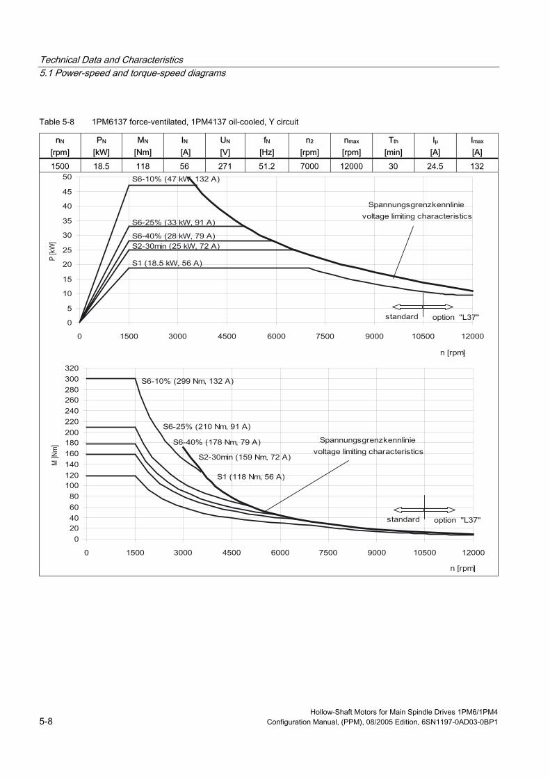
Table 5-8 1PM6137 force-ventilated, 1PM4137 oil-cooled, Y circuit
nN [rpm]
PN [kW]
MN [Nm]
IN [A]
UN [V]
fN [Hz]
n2 [rpm]
nmax [rpm]
Tth [min]
Iμ [A]
Imax [A]
1500 18.5 118 56 271 51.2 7000 12000 30 24.5 132
Hollow-Shaft Motors for Main Spindle Drives 1PM6/1PM4 5-8 Configuration Manual, (PPM), 08/2005 Edition, 6SN1197-0AD03-0BP1

Technical Data and Characteristics 5.1 Power-speed and torque-speed diagrams
Table 5-9 1PM6137 force-ventilated, 1PM4137 oil-cooled, ∆ circuit
nN [rpm]
PN [kW]
MN [Nm]
IN [A]
UN [V]
fN [Hz]
n2 [rpm]
nmax [rpm]
Tth [min]
Iμ [A]
Imax [A]
4000 18.5 44 56 366 133.8 10500 12000 30 37.0 114
Hollow-Shaft Motors for Main Spindle Drives 1PM6/1PM4 Configuration Manual, (PPM), 08/2005 Edition, 6SN1197-0AD03-0BP1 5-9
Technical Data and Characteristics 5.1 Power-speed and torque-speed diagrams
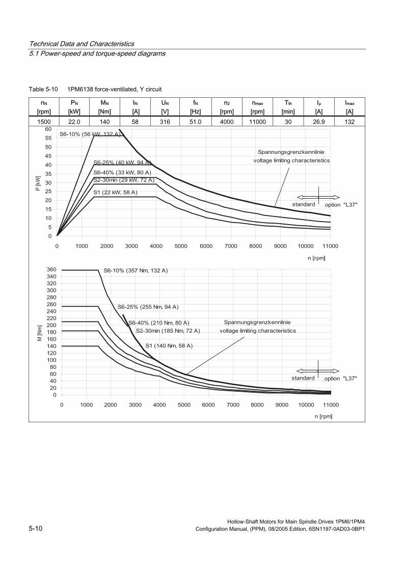
Table 5-10 1PM6138 force-ventilated, Y circuit
nN [rpm]
PN [kW]
MN [Nm]
IN [A]
UN [V]
fN [Hz]
n2 [rpm]
nmax [rpm]
Tth [min]
Iμ [A]
Imax [A]
1500 22.0 140 58 316 51.0 4000 11000 30 26.9 132
Hollow-Shaft Motors for Main Spindle Drives 1PM6/1PM4 5-10 Configuration Manual, (PPM), 08/2005 Edition, 6SN1197-0AD03-0BP1

Technical Data and Characteristics 5.1 Power-speed and torque-speed diagrams
Table 5-11 1PM6138 force-ventilated, ∆ circuit
nN [rpm]
PN [kW]
MN [Nm]
IN [A]
UN [V]
fN [Hz]
n2 [rpm]
nmax [rpm]
Tth [min]
Iμ [A]
Imax [A]
4000 22.0 53 57 400 133.9 6000 11000 30 36.1 123
Hollow-Shaft Motors for Main Spindle Drives 1PM6/1PM4 Configuration Manual, (PPM), 08/2005 Edition, 6SN1197-0AD03-0BP1 5-11
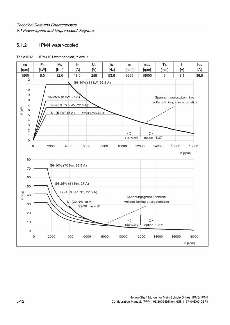
Technical Data and Characteristics 5.1 Power-speed and torque-speed diagrams
5.1.2 1PM4 water-cooled
Table 5-12 1PM4101 water-cooled, Y circuit
nN [rpm]
PN [kW]
MN [Nm]
IN [A]
UN [V]
fN [Hz]
n2 [rpm]
nmax [rpm]
Tth [min]
Iμ [A]
Imax [A]
1500 5.0 32.0 18.0 259 53.6 9665 18000 6 8.1 36.5
Hollow-Shaft Motors for Main Spindle Drives 1PM6/1PM4 5-12 Configuration Manual, (PPM), 08/2005 Edition, 6SN1197-0AD03-0BP1

Technical Data and Characteristics 5.1 Power-speed and torque-speed diagrams
Table 5-13 1PM4105 water-cooled, Y circuit
nN [rpm]
PN [kW]
MN [Nm]
IN [A]
UN [V]
fN [Hz]
n2 [rpm]
nmax [rpm]
Tth [min]
Iμ [A]
Imax [A]
1500 11.0 70.0 38.0 263 53.2 9460 18000 6 16.4 72.0
Hollow-Shaft Motors for Main Spindle Drives 1PM6/1PM4 Configuration Manual, (PPM), 08/2005 Edition, 6SN1197-0AD03-0BP1 5-13

Technical Data and Characteristics 5.1 Power-speed and torque-speed diagrams
Table 5-14 1PM4133 water-cooled, Y circuit
nN [rpm]
PN [kW]
MN [Nm]
IN [A]
UN [V]
fN [Hz]
n2 [rpm]
nmax [rpm]
Tth [min]
Iμ [A]
Imax [A]
1500 15.0 95.5 55.0 229 51.9 8290 15000 11 17.4 116.0
Hollow-Shaft Motors for Main Spindle Drives 1PM6/1PM4 5-14 Configuration Manual, (PPM), 08/2005 Edition, 6SN1197-0AD03-0BP1
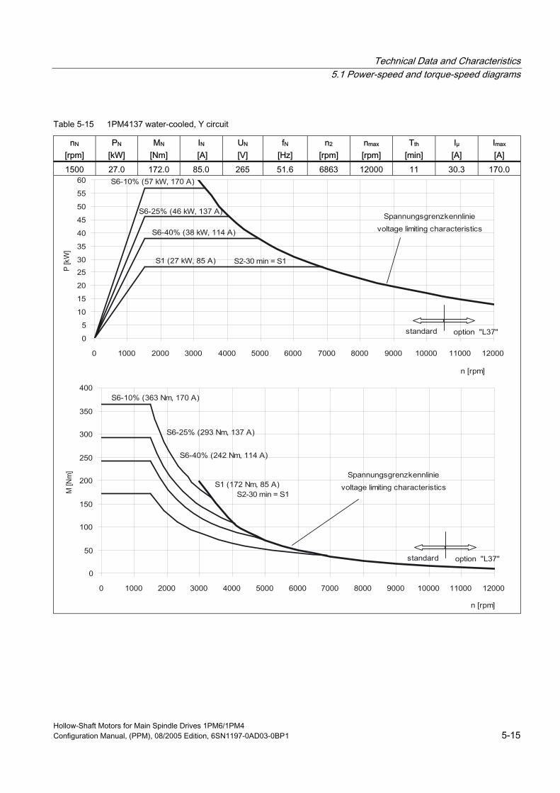
Technical Data and Characteristics 5.1 Power-speed and torque-speed diagrams
Table 5-15 1PM4137 water-cooled, Y circuit
nN [rpm]
PN [kW]
MN [Nm]
IN [A]
UN [V]
fN [Hz]
n2 [rpm]
nmax [rpm]
Tth [min]
Iμ [A]
Imax [A]
1500 27.0 172.0 85.0 265 51.6 6863 12000 11 30.3 170.0
Hollow-Shaft Motors for Main Spindle Drives 1PM6/1PM4 Configuration Manual, (PPM), 08/2005 Edition, 6SN1197-0AD03-0BP1 5-15

Technical Data and Characteristics 5.1 Power-speed and torque-speed diagrams
Hollow-Shaft Motors for Main Spindle Drives 1PM6/1PM4 5-16 Configuration Manual, (PPM), 08/2005 Edition, 6SN1197-0AD03-0BP1
Dimension Drawings 6
Note CAD CREATOR Using a configuration interface that is very easy to understand, CAD CREATOR allows you to quickly find motor-specific
- technical data
- dimension drawings
- 2D/3D CAD data
and supports you when generating plant/system documentation regarding project-specific information and parts lists.
Internet: www.siemens.de/cad-creator
Note Siemens AG reserves the right to change the dimensions of the motors as part of mechanical design improvements without prior notice. This means that dimensions drawings can go out-of-date. Up-to-date dimension drawings can be requested at no charge from your local SIEMENS sales department.
Hollow-Shaft Motors for Main Spindle Drives 1PM6/1PM4 Configuration Manual, (PPM), 08/2005 Edition, 6SN1197-0AD03-0BP1 6-1

Dimension Drawings
Lufta
ustr
itt
( 4x
)
AS
-Wel
lene
nde
BS
-Wel
lene
nde
Typ
ae
cf
kq
1PM
6 10
129
832
933
728
569
627
9
1PM
6 10
540
343
444
239
038
480
1
M1:
2
sign
al c
onne
ctio
n
BS
Wel
lene
nde
air
outle
t
AS
-sha
ft en
dB
S-s
haft
end
b
4±0
.3
2480
±111
7
10Ø
12+
0.5
65
a±1 e
60
160
±0.7
5
190 20
0Ø21
580
-0.3
Ø180j6
14±1
.5
190
190
19
23
122
196
Ø38k6
9
236
259
160
c
17
3845
M16x1.5-RH
Ø11.5
1.5
60°
210.5
18.5
25.5
Ø18-0.003+0.007
(Ø35)
Ø20H7
(Ø38)
Ø18.5 1.5
60°
M16x1.5-LH
Ø35
195
f
q
k±4
122
Ø14+0.5
100-0.5
250
Ø 1
A
Ø0.
04C
0.05
C
Rz 25
Rz
16
Ø0.
007
D
Rz6
.3
DC
M32
x1.5
M16
x1.5
gk 2
30
Sig
nala
nsch
luss
0.00
5D
Rz6.3
A
BS
-saf
t end
inde
xin
form
atio
nda
tena
me;
resp
ons.
repl
acem
ent f
or:
nich
t tol
erie
rte
Maß
e ±2
.5 m
mno
t tol
eran
ced
dim
ensi
ons
±2.5
mm
1
A B C D E F
23
45
67
8
12
34
A B C D E
Bla
tt/sh
eet N
o.
Bla
tt/to
tal s
heet
s
Maß
stab
/sca
le:
1:4
(1:2
)
1PM
6101
Inde
x/M
ittei
lung
/D
atum
/B
earb
.;Ver
antw
./
Dat
um/
Ers
telle
r/
Prü
fer/
A&
D M
C E
WN
S T
24.1
1.20
00
Küm
met
h
Ers
atz
für/
Sie
men
s A
G
Maß
blat
t
510.
3024
0.10
1 1
1PM
610.
Sig
raph
DE
SIG
NW
erks
toff/
mat
eria
lH
albz
eug/
sem
i-fin
ishe
d pa
rtM
odel
l-;S
ach.
-Nr.
/mod
el-;
item
-no.
Ludw
igA
bt./
date
:
prod
ucer
:
insp
ecto
r:
dept
.:
dim
ensi
on s
heet
Hoh
lwel
le, f
. Deu
blin
-Dre
hver
teile
rho
llow
sha
ft, fo
r D
eubl
in-r
otar
yjoi
nt
Fla
nsch
A25
0 D
IN 4
2948
Fla
nsch
und
Wel
lene
nde
DIN
429
55-R
Bau
form
IMB
5, I
MV
1, I
MV
3S
chut
zart
IP55
(W
elle
ndur
chtr
itt IP
54)
Wel
lene
nde
ohne
Paß
fede
rG
eber
sin
/cos
1V
pp 2
56S
/Rvo
rber
eite
t Deu
blin
-Dre
hver
teile
r
flang
e A
250
DIN
429
48fla
nge
and
shaf
t end
DIN
429
55-R
type
of c
onst
uctio
n IM
B 5
, IM
V 1
, IM
V 3
prot
ectio
n cl
ass
IP55
(sh
aft p
assa
ge IP
54)
shaf
t end
with
out f
eath
erke
yen
code
r si
n/co
s 1V
pp 2
56S
/Rpr
epar
ed fo
r D
eubl
in-r
otar
yjoi
nt
Kle
mm
enka
sten
dre
hbar
4x9
0°te
rmin
al b
ox tu
rnab
le 4
x90°
aE
ngl.
Bez
eich
nung
hin
zu04
.05.
05K
üm/L
g
bK
orre
ktur
03.0
8.05
Küm
/Lg
Figure 6-1 1PM6-10 with axial fan
Hollow-Shaft Motors for Main Spindle Drives 1PM6/1PM4 6-2 Configuration Manual, (PPM), 08/2005 Edition, 6SN1197-0AD03-0BP1

Dimension Drawings
Hollow-Shaft Motors for Main Spindle Drives 1PM6/1PM4 Configuration Manual, (PPM), 08/2005 Edition, 6SN1197-0AD03-0BP1 6-3
q
k±4
80±1
231
159
190
4±0
.3
14±1
.5
24
ø180j6
ø38k6
80-0
.3
Lufta
ustr
itt
190
331
M16
x1.5
Typ
AS
-Wel
lene
nde
BS
-Wel
lene
nde
1PM
6 10
1
fk
q
1PM
6 10
5
M 1
:2
273
279
469
378
574
384
sign
al c
onne
ctio
n
AS
-sha
ft en
dB
S-s
haft
end
air
outle
t
c
17
3845
M16x1.5-RH
Ø11.5
1.5
60°
Ø20H7
2
10.5
18.5
25.5
M16x1.5-LH
60°
Ø18-0.003+0.007
(Ø35)
(Ø38)
Ø18.5
f
20
1.5
266
Ø0.
04C
0.05
C
Rz 25
Rz
16
0.00
5D
Ø0.
007
D
Rz
6.3
D
Rz 6.3
C
inde
xin
form
atio
nda
tena
me;
resp
ons.
repl
acem
ent f
or:
nich
t tol
erie
rte
Maß
e ±2
.5 m
mno
t tol
eran
ced
dim
ensi
ons
±2.5
mm
1
A B C D E F
23
45
67
8
12
34
A B C D E
Bla
tt/sh
eet N
o.
Bla
tt/to
tal s
heet
s
Maß
stab
/sca
le:
1:4
(1:2
) 1
PM
6101
Inde
x/M
ittei
lung
/D
atum
/B
earb
.;Ver
antw
./
Dat
um/
Ers
telle
r/
Prü
fer/
A&
D M
C E
WN
S T
08.0
2.20
00
Küm
met
h
Ers
atz
für/
Sie
men
s A
G
Maß
blat
t
510.
3108
3.10
1 1
1PM
610.
Sig
raph
DE
SIG
NW
erks
toff/
mat
eria
lH
albz
eug/
sem
i-fin
ishe
d pa
rtM
odel
l-;S
ach.
-Nr.
/mod
el-;
item
-no.
Ludw
igA
bt./
date
:
prod
ucer
:
insp
ecto
r:
dept
.:
dim
ensi
on s
heet
Hoh
lwel
le, f
. Deu
blin
-Dre
hver
teile
rho
llow
sha
ft, fo
r D
eubl
in-r
otar
yjoi
nt
Fla
nsch
A25
0 D
IN 4
2948
Fla
nsch
und
Wel
lene
nde
DIN
429
55-R
Bau
form
IMB
5, I
MV
1, I
MV
3
Sch
utza
rt IP
55 (
Wel
lend
urch
tritt
IP54
)
Wel
lene
nde
ohne
Paß
fede
r
Geb
er s
in/c
os 1
Vpp
-256
S/R
vorb
erei
tet D
eubl
in-D
rehv
erte
iler
flang
e A
250
DIN
429
48
flang
e an
d sh
aft e
nd D
IN 4
2955
-R
type
of c
onst
uctio
n IM
B 5
, IM
V 1
, IM
V 3
prot
ectio
n cl
ass
IP55
(sh
aft p
assa
ge IP
54)
shaf
t end
with
out f
eath
erke
y
enco
der
sin/
cos
1Vpp
256
S/R
prep
ared
for
Deu
blin
-rot
aryj
oint
Geb
läse
dre
hbar
4x9
0°K
lem
men
kast
en d
rehb
ar 4
x90°
blow
er tu
rnab
le 4
x90°
term
inal
box
turn
able
4x9
0°
aM
etr.
Gew
. hin
zu19
.01.
01K
üm/P
fl
b1P
M61
07 u
. Eng
l.-B
ez.h
inzu
04.0
5.05
Küm
/Lg
cK
orre
ktur
03.0
8.05
Küm
/Lg
117
23
19
Ø35
gk 2
30
Ø14+0.5
250
196
Ø21
5±0
.5
122
Sig
nala
nsch
luß
M32
x1.5
Figure 6-2 1PM6-10 with radial fan

Dimension Drawings
Hollow-Shaft Motors for Main Spindle Drives 1PM6/1PM4 6-4 Configuration Manual, (PPM), 08/2005 Edition, 6SN1197-0AD03-0BP1
sign
al c
onne
ctio
n
BS
-sha
ft en
dair
outle
t
AS
-sha
ft en
dB
S-s
haft
end
a04
.05.
05K
üm/L
gE
ngl.
Bez
eich
nung
hin
zu
b
f
q
a±1
110
±2
e
159
333
140
k±4
2
Ø35
254
BS
-Wel
lene
nde
245
Ø12
+0.
5
15
30
64
307
5±0
.3
15±1
.5
ø250h6
28
ø42k6
110
-0.3
Ø12
+0.
5
65
132
25
27
Sig
nala
nsch
luß
14
132-0.5
Ø18+0.5
350
46
216
±0.7
5
245
260
300
152
gk 3
30M
40x1
.5
Lufta
ustr
itt
252
M16
x1.5
M 1
:2
1.5
AS
-Wel
lene
nde
BS
-Wel
lene
nde
1PM
6137
436
484
481
914
514
424
544
614
(4x)
17
3845
M16x1.5-RH
Ø11.5
1.5
60°
Ø20H7
2
10.5
18.5
25.5
M16x1.5-LH
Ø18-0.003+0.007
(Ø35)
(Ø42)
Ø18.5
c
60°
Ø0.
04C
0.05
C
Rz 25
Rz
16
0.00
5D
Ø0.
007
D
Rz
6.3
D
Rz 6.3
C
AØ
1A
Typ
ae
cf
kq
1PM
6 13
331
636
436
179
439
4
1PM
6 13
850
655
455
158
498
4
inde
xin
form
atio
nda
tena
me;
resp
ons.
repl
acem
ent f
or:
nich
t tol
erie
rte
Maß
e ±2
.5 m
mno
t tol
eran
ced
dim
ensi
ons
±2.5
mm
1
A B C D E F
23
45
67
8
12
34
A B C D E
Bla
tt/sh
eet N
o.
Bla
tt/to
tal s
heet
s
Maß
stab
/sca
le: 1
:5 (
1:2)
1P
M61
33
Inde
x/M
ittei
lung
/D
atum
/B
earb
.;Ver
antw
./
Dat
um/
Ers
telle
r/
Prü
fer/
A&
D M
C E
WN
S T
23.1
1.20
00
Küm
met
h
Ers
atz
für/
Sie
men
s A
G
Maß
blat
t
510.
3024
2.10
1 1
1PM
613.
Sig
raph
DE
SIG
NW
erks
toff/
mat
eria
lH
albz
eug/
sem
i-fin
ishe
d pa
rtM
odel
l-;S
ach.
-Nr.
/mod
el-;
item
-no.
Ludw
igA
bt./
date
:
prod
ucer
:
insp
ecto
r:
dept
.:
dim
ensi
on s
heet
Hoh
lwel
le, f
. Deu
blin
-Dre
hver
teile
rho
llow
sha
ft, fo
r D
eubl
in-r
otar
yjoi
nt
Fla
nsch
A25
0 D
IN 4
2948
Fla
nsch
und
Wel
lene
nde
DIN
429
55-R
Bau
form
IMB
5, I
MV
1, I
MV
3S
chut
zart
IP55
(W
elle
ndur
chtr
itt IP
54)
Wel
lene
nde
ohne
Paß
fede
rG
eber
sin
/cos
1V
pp 2
56S
/Rvo
rber
eite
t Deu
blin
-Dre
hver
teile
r
flang
e A
250
DIN
429
48fla
nge
and
shaf
t end
DIN
429
55-R
type
of c
onst
uctio
n IM
B 5
, IM
V 1
, IM
V 3
prot
ectio
n cl
ass
IP55
(sh
aft p
assa
ge IP
54)
shaf
t end
with
out f
eath
erke
yen
code
r si
n/co
s 1V
pp 2
56S
/Rpr
epar
ed fo
r D
eubl
in-r
otar
yjoi
nt
Kle
mm
enka
sten
dre
hbar
4x9
0°te
rmin
al b
ox tu
rnab
le 4
x90°
bK
orre
ktur
03.0
8.05
Küm
/Lg
Figure 6-3 1PM6-13 with axial fan
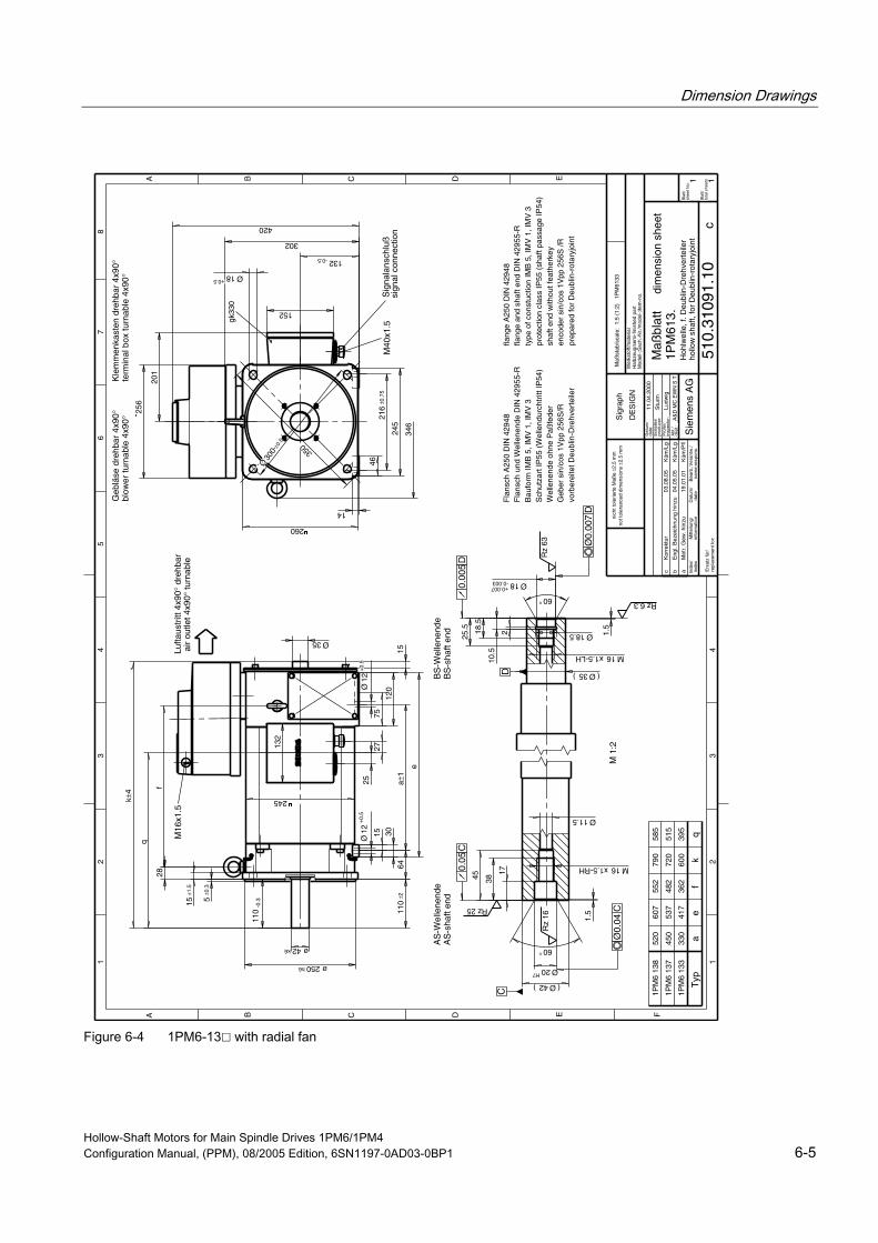
Dimension Drawings
Hollow-Shaft Motors for Main Spindle Drives 1PM6/1PM4 Configuration Manual, (PPM), 08/2005 Edition, 6SN1197-0AD03-0BP1 6-5
Lufta
ustr
itt 4
x90°
dre
hbar
M 1
:2
Typ
1PM
6 13
3
1PM
6 13
7
1PM
6 13
8
ae
fk
q
330
450
520
417
537
607
362
482
552
600
720
790
395
515
585
air
outle
t 4x9
0° tu
rnab
le
sign
al c
onne
ctio
n
AS
-sha
ft en
dB
S-s
haft
end
a
Eng
l. B
ezei
chnu
ng h
inzu
04.0
5.05
Küm
/Lg
b
Met
r. G
ew. h
inzu
19.0
1.01
Küm
/Pfl
c
cK
orre
ktur
03.0
8.05
Küm
/Lg
110
±2
302
201
256
28f
q
15
216
±0.7
5
346
1.5
30
a±1
Ø12
+0.
5
120
e
1525
27132
152
75
64
14
Ø12
+0.
5
M16
x1.5
gk33
0
245
5±0
.3
15±1
.5
ø250h6
ø42k6
110
-0.3
132-0.5
245
Ø18+0.5
350
260
Ø30
0±0
.5
46
M40
x1.5
k±4
Sig
nala
nsch
luß
420
Ø35
AS
-Wel
lene
nde
BS
-Wel
lene
nde
17
3845
M16x1.5-RH
Ø11.5
1.5
60°
Ø20H7
2
10.5
18.5
25.5
M16x1.5-LH
60°
Ø18-0.003+0.007
(Ø35)
(Ø42)
Ø18.5
Ø0.
04C
0.05
C
Rz 25
Rz
16
0.00
5D
Ø0.
007
D
Rz
63
D
Rz 6.3
C
inde
xin
form
atio
nda
tena
me;
resp
ons.
repl
acem
ent f
or:
nich
t tol
erie
rte
Maß
e ±2
.5 m
mno
t tol
eran
ced
dim
ensi
ons
±2.5
mm
1
A B C D E F
23
45
67
8
12
34
A B C D E
Bla
tt/sh
eet N
o.
Bla
tt/to
tal s
heet
s
Maß
stab
/sca
le:
1:5
(1:2
) 1
PM
6133
Inde
x/M
ittei
lung
/D
atum
/B
earb
.;Ver
antw
./
Dat
um/
Ers
telle
r/
Prü
fer/
A&
D M
C E
WN
S T
11.0
4.20
00
Stu
rm
Ers
atz
für/
Sie
men
s A
G
Maß
blat
t
510.
3109
1.10
1 1
1PM
613.
Sig
raph
DE
SIG
NW
erks
toff/
mat
eria
lH
albz
eug/
sem
i-fin
ishe
d pa
rtM
odel
l-;S
ach.
-Nr.
/mod
el-;
item
-no.
Ludw
igA
bt./
date
:
prod
ucer
:
insp
ecto
r:
dept
.:
dim
ensi
on s
heet
Hoh
lwel
le, f
. Deu
blin
-Dre
hver
teile
rho
llow
sha
ft, fo
r D
eubl
in-r
otar
yjoi
nt
Fla
nsch
A25
0 D
IN 4
2948
Fla
nsch
und
Wel
lene
nde
DIN
429
55-R
Bau
form
IMB
5, I
MV
1, I
MV
3S
chut
zart
IP55
(W
elle
ndur
chtr
itt IP
54)
Wel
lene
nde
ohne
Paß
fede
rG
eber
sin
/cos
1V
pp 2
56S
/Rvo
rber
eite
t Deu
blin
-Dre
hver
teile
r
flang
e A
250
DIN
429
48fla
nge
and
shaf
t end
DIN
429
55-R
type
of c
onst
uctio
n IM
B 5
, IM
V 1
, IM
V 3
prot
ectio
n cl
ass
IP55
(sh
aft p
assa
ge IP
54)
shaf
t end
with
out f
eath
erke
yen
code
r si
n/co
s 1V
pp 2
56S
/Rpr
epar
ed fo
r D
eubl
in-r
otar
yjoi
nt
Geb
läse
dre
hbar
4x9
0°K
lem
men
kast
en d
rehb
ar 4
x90°
blow
er tu
rnab
le 4
x90°
term
inal
box
turn
able
4x9
0°
Figure 6-4 1PM6-13 with radial fan
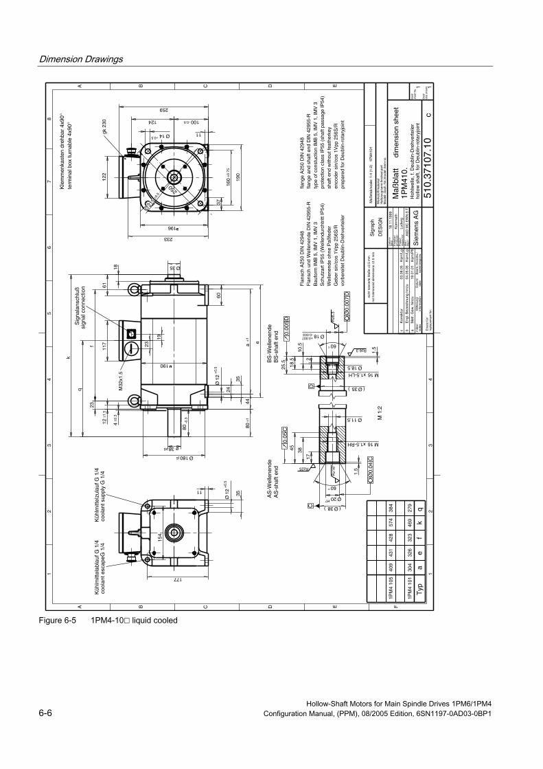
Dimension Drawings
Hollow-Shaft Motors for Main Spindle Drives 1PM6/1PM4 6-6 Configuration Manual, (PPM), 08/2005 Edition, 6SN1197-0AD03-0BP1
Typ
kq
ae
1PM
4 10
1
1PM
4 10
5
469
574
279
384
304
409
326
431
AS
-Wel
lene
nde
BS
-Wel
lene
nde
M 1
:2
ab
Met
r. G
ew. h
inzu
Eng
l. B
ezei
chnu
ng h
inzu
19.0
1.01
04.0
5.05
Küm
/Pfl
Küm
/Lg
Sig
nala
nsch
luß
Küh
lmitt
elab
lauf
G 1
/4K
ühlm
ittel
zula
uf G
1/4
AS
-sha
ft en
dB
S-s
haft
end
q
k
a±1
80±1
e
124
233
259
154
177
1.5
17
3845
1.5
2
10.5
18.5
25.5
Ø18-0.003+0.007
60°
Ø20H7
(Ø38)
M16x1.5-RH
Ø11.5
M16x1.5-LHØ18.5
(Ø35)
Ø35
18
250
D
0.00
5D
Ø0.
007
D
Ø0.
04C
C
0.05
C
Rz1
6R
z6.3
Rz25
Rz6.3
190
4±0
.3
12±1
.5
Ø12
+0.
5
24
35
44
Ø180j6
80-0
.3
ø38k6
f323
428
23
60
f
61
60°in
dex
info
rmat
ion
date
nam
e;re
spon
s.
repl
acem
ent f
or:
nich
t tol
erie
rte
Maß
e ±2
.5 m
mno
t tol
eran
ced
dim
ensi
ons
±2.5
mm
1
A B C D E F
23
45
67
8
12
34
A B C D E
Bla
tt/sh
eet N
o.
Bla
tt/to
tal s
heet
s
Maß
stab
/sca
le: 1
:4 (
1:2)
1P
M41
01
Inde
x/M
ittei
lung
/D
atum
/B
earb
.;Ver
antw
./
Dat
um/
Ers
telle
r/
Prü
fer/
A&
D M
C E
WN
S T
18.1
1.19
99
Küm
met
h
Ers
atz
für/
Sie
men
s A
G
Maß
blat
t
510.
3710
7.10
1 1
1PM
410.
Sig
raph
DE
SIG
NW
erks
toff/
mat
eria
lH
albz
eug/
sem
i-fin
ishe
d pa
rtM
odel
l-;S
ach.
-Nr.
/mod
el-;
item
-no.
Ludw
igA
bt./
date
:
prod
ucer
:
insp
ecto
r:
dept
.:
dim
ensi
on s
heet
Hoh
lwel
le, f
. Deu
blin
-Dre
hver
teile
rho
llow
sha
ft, fo
r D
eubl
in-r
otar
yjoi
nt
Fla
nsch
A25
0 D
IN 4
2948
Fla
nsch
und
Wel
lene
nde
DIN
429
55-R
Bau
form
IMB
5, I
MV
1, I
MV
3S
chut
zart
IP55
(W
elle
ndur
chtr
itt IP
54)
Wel
lene
nde
ohne
Paß
fede
rG
eber
sin
/cos
1V
pp 2
56S
/Rvo
rber
eite
t Deu
blin
-Dre
hver
teile
r
flang
e A
250
DIN
429
48fla
nge
and
shaf
t end
DIN
429
55-R
type
of c
onst
uctio
n IM
B 5
, IM
V 1
, IM
V 3
prot
ectio
n cl
ass
IP55
(sh
aft p
assa
ge IP
54)
shaf
t end
with
out f
eath
erke
yen
code
r si
n/co
s 1V
pp 2
56S
/Rpr
epar
ed fo
r D
eubl
in-r
otar
yjoi
nt
Kle
mm
enka
sten
dre
hbar
4x9
0°te
rmin
al b
ox tu
rnab
le 4
x90°
c
cK
orre
ktur
03.0
8.05
Küm
/Lg
117 23
19
11
100-0.5
196
Ø14+0.5
37
160
±0.7
5
190
Ø21
5±0
.5
122
gk 2
30
Ø12
+0.
5
35
11
cool
ant e
scap
eG 1
/4co
olan
t sup
ply
G 1
/4
M32
x1.5
sign
al c
onne
ctio
n
Figure 6-5 1PM4-10 liquid cooled
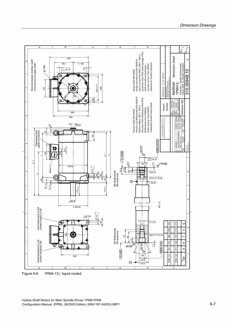
Dimension Drawings
Hollow-Shaft Motors for Main Spindle Drives 1PM6/1PM4 Configuration Manual, (PPM), 08/2005 Edition, 6SN1197-0AD03-0BP1 6-7
q
Sig
nala
nsch
luß
Küh
lmitt
elab
lauf
G 3
/8K
ühlm
ittel
zula
uf G
3/8
AS
-sha
ft en
dB
S-s
haft
end
aM
etr.
Gew
. hin
zu19
.01.
01K
üm/P
fl
bE
ngl.
Bez
eich
nung
hin
zu09
.05.
05K
üm/L
g
c
cK
orre
ktur
03.0
8.05
Küm
/Lg
q
k±4
a±1
110
±2
e
159
302
335
60°245
5±0
.3
16±1
.5
Ø12
+0.
5
24 36
53
Ø250h6
235
206
ø42k6
110
-0.3
85
Ø35
16
25
132
27
14
132-0.5
260
Ø18+0.5
350
43
216
±0.7
5
246
Ø30
0±0
.5
152
gk 3
30
1.5 RZ 6.3
Ø12
+0.
5
35
14
cool
ant e
scap
eG 3
/8co
olan
t sup
ply
G 3
/8
M40
x1.5
sign
al c
onne
ctio
n
Typ
ae
fk
1PM
4 13
3
1PM
4 13
7
377
497
400
520
379
499
578
698
374
494
f45
M 1
:2
AS
-Wel
lene
nde
BS
-Wel
lene
nde
17
3845
M16x1.5-RH
Ø11.5
1.5
60°
Ø20H7
2
10.5
18.5
25.5
M16x1.5-LH
Ø18-0.003+0.007
(Ø35)
(Ø42)
Ø18.5
61
Ø0.
04C
0.05
C
Rz 25
Rz
16
0.00
5D
Ø0.
007
D
Rz
6.3
DC
inde
xin
form
atio
nda
tena
me;
resp
ons.
repl
acem
ent f
or:
nich
t tol
erie
rte
Maß
e ±2
.5 m
mno
t tol
eran
ced
dim
ensi
ons
±2.5
mm
1
A B C D E F
23
45
67
8
12
34
A B C D E
Bla
tt/sh
eet N
o.
Bla
tt/to
tal s
heet
s
Maß
stab
/sca
le:
1:5
(1:2
) 1
PM
4133
Inde
x/M
ittei
lung
/D
atum
/B
earb
.;Ver
antw
./
Dat
um/
Ers
telle
r/
Prü
fer/
A&
D M
C E
WN
S T
06.0
4.20
00
Küm
met
h
Ers
atz
für/
Sie
men
s A
G
Maß
blat
t
510.
3094
8.10
1 1
1PM
413.
Sig
raph
DE
SIG
NW
erks
toff/
mat
eria
lH
albz
eug/
sem
i-fin
ishe
d pa
rtM
odel
l-;S
ach.
-Nr.
/mod
el-;
item
-no.
Ludw
igA
bt./
date
:
prod
ucer
:
insp
ecto
r:
dept
.:
dim
ensi
on s
heet
Hoh
lwel
le, f
. Deu
blin
-Dre
hver
teile
rho
llow
sha
ft, fo
r D
eubl
in-r
otar
yjoi
nt
Fla
nsch
A25
0 D
IN 4
2948
Fla
nsch
und
Wel
lene
nde
DIN
429
55-R
Bau
form
IMB
5, I
MV
1, I
MV
3S
chut
zart
IP55
(W
elle
ndur
chtr
itt IP
54)
Wel
lene
nde
ohne
Paß
fede
rG
eber
sin
/cos
1V
pp 2
56S
/Rvo
rber
eite
t Deu
blin
-Dre
hver
teile
r
flang
e A
250
DIN
429
48fla
nge
and
shaf
t end
DIN
429
55-R
type
of c
onst
uctio
n IM
B 5
, IM
V 1
, IM
V 3
prot
ectio
n cl
ass
IP55
(sh
aft p
assa
ge IP
54)
shaf
t end
with
out f
eath
erke
yen
code
r si
n/co
s 1V
pp 2
56S
/Rpr
epar
ed fo
r D
eubl
in-r
otar
yjoi
nt
Kle
mm
enka
sten
dre
hbar
4x9
0°te
rmin
al b
ox tu
rnab
le 4
x90°
Figure 6-6 1PM4-13 liquid cooled

Dimension Drawings
Hollow-Shaft Motors for Main Spindle Drives 1PM6/1PM4 6-8 Configuration Manual, (PPM), 08/2005 Edition, 6SN1197-0AD03-0BP1
Appendix A A.1 References
An overview of publications that is updated monthly is provided in a number of languages in the Internet at:
<http://www.siemens.com/motioncontrol> erview" through "Support", "Technical Documentation", "Documentation Ov
General Documentation
/D 21.2/ SINAMICS S120 Catalog SINAMICS S120
Servo Control Drive System
/NC 60/ SINUMERIK and SIMODRIVE Catalog Automation Systems for Machine Tools
/DA65.3/ SIMOVERT MASTERDRIVES Catalog Synchronous and Induction Motors for SIMOVERT MASTERDRIVES
Electronic Documentation
/CD1/ DOC ON CD The SINUMERIK System
(includes all SINUMERIK 840D/810D and SIMODRIVE 611D)
/CD2/ DOC ON CD The SINAMICS System
Hollow-Shaft Motors for Main Spindle Drives 1PM6/1PM4 Configuration Manual, (PPM), 08/2005 Edition, 6SN1197-0AD03-0BP1 A-1

Appendix A.1 References
Manufacturer/Service Documentation
/PJAL/ Configuration Manual, Synchronous Motors SINAMICS S120, SIMODRIVE 611, SIMOVERT MASTERDRIVES
Synchronous Motors General Section
/PFK7S/ Configuration Manual, Synchronous Motors SINAMICS S120
1FK7 Synchronous Motors
/PFT6S/ Configuration Manual, Synchronous Motors SINAMICS S120
1FT6 Synchronous Motors
/APH7S/ Configuration Manual, Induction Motors SINAMICS S120
Servo Control/Vector Control Induction Motors 1PH7
/PMH2/ Configuration Manual, Hollow-Shaft Measuring System SINAMICS S120, SIMODRIVE 611, SIMOVERT MASTERDRIVES,
SIMAG H2 Hollow-Shaft Measuring System
/PJM2/ Configuration Manual, Synchronous Motors SIMODRIVE 611, SIMOVERT MASTERDRIVES
Synchronous Motors General Section, 1FT5, 1FT6, 1FK6, 1FK7
/PFK7/ Configuration Manual, Synchronous Motors SIMODRIVE 611, SIMOVERT MASTERDRIVES
1FK7 Synchronous Motors
/PFT6/ Configuration Manual, Synchronous Motors SIMODRIVE 611, SIMOVERT MASTERDRIVES
1FT6 Synchronous Motors
Hollow-Shaft Motors for Main Spindle Drives 1PM6/1PM4 A-2 Configuration Manual, (PPM), 08/2005 Edition, 6SN1197-0AD03-0BP1
Appendix A.1 References
/PFK6/ Configuration Manual, Synchronous Motors SIMODRIVE 611, SIMOVERT MASTERDRIVES
1FK6 Synchronous Motors
/PFS6/ Configuration Manual, Synchronous Motors SIMOVERT MASTERDRIVES
1FS6 Synchronous Motors, Explosion-Protected
/PFU/ Configuration Manual, Synchronous Motors SINAMICS S120, SIMOVERT MASTERDRIVES, MICROMASTER
SIEMOSYN Synchronous Motors 1FU8
/ASAL/ Configuration Manual, Induction Motors SIMODRIVE 611, SIMOVERT MASTERDRIVES
Induction Motors General Section
/APH2/ Configuration Manual, Induction Motors SIMODRIVE 611
1PH2 Induction Motors
/APH4/ Configuration Manual, Induction Motors SIMODRIVE 611
1PH4 Induction Motors
/APH7/ Configuration Manual, Induction Motors SIMODRIVE 611
1PH7 Induction Motors
/PPM/ Configuration Manual, Hollow-Shaft Motors SIMODRIVE 611
Hollow-Shaft Motors for Main Spindle Drives 1PM6 and 1PM4
/PJFE/ Configuration Manual, Synchronous Build-in Motors SIMODRIVE 611
Synchronous Motors for Main Spindle Drives 1FE1 Synchronous Build-in Motors
Hollow-Shaft Motors for Main Spindle Drives 1PM6/1PM4 Configuration Manual, (PPM), 08/2005 Edition, 6SN1197-0AD03-0BP1 A-3
Appendix A.1 References
/PJTM/ Configuration Manual, Build-in Torque Motors SIMODRIVE 611
Build-in Torque Motors 1FW6
/PJLM/ Configuration Manual, Linear Motors SIMODRIVE 611
Linear Motors 1FN1 and 1FN3
/PMS/ Configuration Manual, ECO Motor Spindle SIMODRIVE 611
ECO Motor Spindle 2SP1
/APL6/ Configuration Manual, Induction Motors SIMOVERT MASTERDRIVES
Induction Motors 1PL6
/APH7M/ Configuration Manual, Induction Motors SIMOVERT MASTERDRIVES VC/MC
Induction Motors 1PH7
/PKTM/ Configuration Manual, Complete Torque Motors SIMOVERT MASTERDRIVES
Complete Torque Motors 1FW3
Hollow-Shaft Motors for Main Spindle Drives 1PM6/1PM4 A-4 Configuration Manual, (PPM), 08/2005 Edition, 6SN1197-0AD03-0BP1

Index A H Additive, 3-17 Hollow-shaft encoders, 2-17 Applications, 1-1, 1-3 Hotline, iii Axial force, 3-6
I B Induction motors
Mode of operation, 2-3 Balancing process, 3-3 Bearing change intervals, 3-5
K C KTY 84 PTC thermistor, 2-15 Cantilever force, 3-6 Characteristics, 5-1
L Connecting motors, 2-8 Connecting-up information, 2-13 Limit speed, 3-4 Connection system Liquid cooling Cross-sections, 2-10 Oil, 3-15 Star/delta circuit configuration, 2-9 Water, 3-16 Connection values, separately driven fan, 3-20 Continuous speed, 3-4 Cooling, 3-8 M Cooling medium, 3-16 Cooling-lubricating medium gland, 3-9 Maximum continuous speed, 2-1
Maximum current, 2-2 Maximum torque, 2-1
D Mechanical limit speed, 2-1 Mechanical limiting, 2-7 Dimension drawings, 6-1 Motor rating plate, 2-14 Drive converter systems, 2-6
N E No-load current, 2-2 Encoders, 2-17
ESDS instructions, vi
P F Power characteristics, 2-4
Power–speed diagram, 2-5 Forced ventilation, 3-19
Hollow-Shaft Motors for Main Spindle Drives 1PM6/1PM4 Configuration Manual, (PPM), 08/2005 Edition, 6SN1197-0AD03-0BP1 Index-1

Index
R Rated current, 2-2, 5-1 Rated frequency, 2-2 Rated power, 2-2 Rated speed, 2-2, 5-1 Rated torque, 2-2 Recommended connection, 3-20
S S1 duty, 2-2 S6 duty, 2-3 Signal cable, 2-18 SIMODRIVE 611, 2-6 Speed n2, 2-1
T Technical data, 5-1 Technical Support, iii Thermal limiting, 2-7 Thermal motor protection, 2-15 Thermal time constant, 2-3 Types of construction, 3-1
V Vibration severity limit values, 3-2
Hollow-Shaft Motors for Main Spindle Drives 1PM6/1PM4 Index-2 Configuration Manual, (PPM), 08/2005 Edition, 6SN1197-0AD03-0BP1
Suggestions
Corrections
To
SIEMENS AG
A&D MC BMS
Postfach 3180
D-91050 Erlangen
Tel.: +49 (0) 180 / 5050 - 222 (Service Support)
Fax: +49 (0) 9131 / 98 – 63315 (Documentation)
email: [email protected]
For Publication/Manual:
Hollow-Shaft Motors for
Main Spindle Drives
1PM6/1PM4
Manufacturer/Service Documentation
Configuration Manual
Order No.: 6SN1197-0AD03-0BP1
Edition: 08.2005
From
Name
Company/Department
Address
Postal code: Town:
Telephone: /
Telefax: /
If you come across any printing errors in this
document, please let us know using this form.
We would also be grateful for any suggestions and
recommendations for improvement.
Suggestions and/or corrections


