hollow american national standard metal ansi/ hmma 862 … · ansi/naamm hmma 862-13 commercial...
TRANSCRIPT
8d
A
NS
I/NA
AM
M H
MM
A 8
62
-13
Au
gu
st 5
, 201
3
ME
TA
L D
OO
RS
& F
RA
ME
S
8d
A
NS
I/N
AA
MM
HM
MA
862-1
3
Au
gu
st
5,
201
3
ME
TA
L D
OO
RS
& F
RA
ME
S
HOLLOW
AMERICAN NATIONAL STANDARD
METAL MANUAL
ANSI/ NAAMM HMMA 862 -13
GUIDE SPECIFICATIONS FOR COMMERCIAL SECURITY HOLLOW
METAL DOORS AND FRAMES
A Division of
HOLLOW METAL MANUFACTURERS
A S S O C I A T I O N NATIONAL ASSOCIATION OF
ARCHITECTURAL METAL MANUFACTURERS
National Association of Architectural Metal Manufacturers
8 South Michigan Avenue
Chicago, Illinois 60603
Tel: 312-332-0405 • Fax: 312-332-0706
Copyright © 1985, 1987, 1990, 1998, 2003
National Association of Architectural Metal Manufacturers All Rights Reserved
Approval of an American National Standard requires verification by ANSI
that the requirements for due process, consensus, and other criteria for
approval have been met by the standards developer.
Consensus is established when, in the judgment of the ANSI Board of
Standards Review, substantial agreement has been reached by directly
and materially affected interests. Substantial agreement means much
more than a simple majority, but not necessarily unanimity. Consensus
requires that all views and objections be considered, and that a concert-
ed effort be made toward their resolution.
The use of American National Standards is completely voluntary; their
existence does not in any respect preclude anyone, whether they have
approved the standards or not, from manufacturing, marketing, purchas-
ing, or using products, processes, or procedures not conforming to the
standards.
The American National Standards Institute does not develop standards
and will in no circumstances give an interpretation of any American
National Standard. Moreover, no person shall have the right or authority
to issue an interpretation of an American National Standard in the name
of the American National Standards Institute. Requests for interpretation
should be addressed to the sponsor whose name appears on the title
page of this standard.
CAUTION NOTICE: This American National Standard can be revised or
withdrawn at any time. The procedures of the American National
Standards Institute require that action be taken periodically to reaffirm,
revise, or withdraw this standard. Purchasers of American National
Standards can receive current information on all standards by calling or
writing the American National Standards Institute.
This standard was developed by representative members of the Hollow
Metal Manufacturers Association Division (HMMA) of the National
Association of Architectural Metal Manufacturers (NAAMM) to provide
their opinion and guidance on the specification and use of commercial
security hollow metal doors and frames. This standard contains advisory
information only and is published as a public service by NAAMM and its
HMMA Division. NAAMM and its HMMA Division disclaim all liability of
any kind for the use, application, or adaptation of material published in this
standard.
Purchasers of NAAMM Standards can receive current information on all
NAAMM Standards by calling, writing, or visiting the website of the
National Association of Architectural Metal Manufacturers at
www.naamm.org.
National Association of Architectural Metal Manufacturers
800 Roosevelt Road
Bldg. C, Suite 312
Glen Ellyn, Illinois 60137
Phone: (630) 942-6591 Fax: (630) 790-3095
www.naamm.org
Copyright © 2013
National Association of Architectural Metal Manufacturers
All Rights Reserved
ANSI/NAAMM HMMA 862-13 COMMERCIAL SECURITY HOLLOW METAL DOORS AND FRAMES i
TABLE OF CONTENTS
Introduction..................................................................................................................................................ii
Foreword .....................................................................................................................................................iv
Part 1 – GENERAL
1.01 Summary...........................................................................................................................................1
1.02 Products Provided Under This Section...........................................................................................1
1.03 Related Sections..............................................................................................................................1
1.04 References .......................................................................................................................................2
1.05 Testing and Performance ...............................................................................................................3
1.06 Quality Assurance ...........................................................................................................................7
1.07 Submittals .........................................................................................................................................8
1.08 Warranty ...........................................................................................................................................8
Part 2 – PRODUCTS
2.01 Commercial Security Hollow Metal Doors ...................................................................................9
2.02 Commercial Security Hollow Metal Panels ................................................................................11
2.03 Commercial Security Hollow Metal Frames ...............................................................................11
2.04 Manufacturing Tolerances ...........................................................................................................14
2.05 Hardware Locations......................................................................................................................15
2.06 Finish ................................................................................................................................................16
Part 3 – EXECUTION
3.01 Site Storage and Protection of Materials ...................................................................................16
3.02 Installation ......................................................................................................................................16
3.03 Clearances.....................................................................................................................................18
Table .........................................................................................................................................................19
Figures ........................................................................................................................................................20
APPENDIX (Not part of the Standard)
X1. Guide Lines for Use .............................................................................................................................29
Steel Tables NAAMM/HMMA – 803 .........................................................................................................40

ii SOUND CONTROL HOLLOW METAL DOORS AND FRAMES ANSI/NAAMM HMMA 862-13
INTRODUCTION
COMMERCIAL SECURITY HOLLOW METAL SYSTEMS
For many years, hollow metal door and framing systems have been used as the primary and initial defense
against forced entry. Architects, specifiers, and end users have come to understand the advantages of using
hollow metal doors and frames in commercial security applications, such as, airports, convention centers,
hotels, and offices, and in foreign and domestic government buildings such as, embassies, offices, and
barracks.
The original standard, ANSI/NAAMM HMMA 862-03, was developed to provide guidance in the specification
of commercial security hollow metal doors and frames where protection from vandalism, forced entry, theft,
and firearms attack is a paramount concern.
It is necessary when writing a commercial security specification to keep in mind the security aspects of the
entire opening – door, frame, hardware, glazing and wall construction. The test performance criteria set forth
in this document simulates the “total opening” and its ability to frustrate forced entry, and ballistic penetration.
DESIGN VERSATILITY
Commercial hollow metal construction provides the architect with a great deal of freedom in the design of
hollow metal products. The architect can also take advantage of the expertise acquired by those hollow metal
manufacturers experienced in commercial security work. Over the years NAAMM/HMMA manufacturers have
developed advanced methods and equipment enabling them to efficiently manufacture hollow metal
assemblies, which address today’s difficult commercial security applications. These applications include
working with the latest in burglary and bullet resisting hardware and security glazing. A number of these
manufacturers offer proven economical and functional designs of commercial security hollow metal systems.
EVALUATING COMMERCIAL SECURITY HOLLOW METAL SYSTEMS
In order to evaluate the performance of commercial security hollow metal, it has been necessary to develop
testing methods which simulate in the laboratory the system’s ability to frustrate attacks initiated by unskilled,
semi-skilled and skilled burglars and/or the system’s ability to resist ballistic penetrations. One objective of this
development work is to provide a standardized means of measuring performance which architects can call for
in their specifications. Another objective is to provide manufacturers standardized means of testing and
inspecting their products, improving their designs and maintaining high quality construction. Finally,
maintenance of rigorous standards and methods of testing construction and performance gives assurance of
protection to the end user and the public in general. The performance requirement and methods of testing set
forth in this voluntary standard will go a long way towards realizing the stated objectives.
TESTING
This standard for commercial security hollow metal has been developed to allow architects to specify doors
and frames based on the level of security required for specific openings. There are six Security Rating
Classifications, 1 being the lowest or least secure, and 6 being the highest rating. This standard considers two
conditions, Forced Entry Resistance and Ballistic Resistance. There are tests described by this specification
which are to be conducted in accordance with; ASTM F1450, “Standard Test Methods for Hollow Metal
Swinging Door Assemblies for Detention and Correctional Facilities”; ASTM F1592, “Standard Test Methods
for Detention Hollow Metal Vision Systems”; SD-STD-01.01, Revision G, 1993; “Certification Standard on
Forced Entry and Ballistic Resistance of Structural Systems”; UL Standard 752, “Bullet Resisting Equipment”;
and LPS 1175: Issue 5 (2000), “Specification for Testing and Classifying the Burglary Resistance of Building
Components, Strong Points and Security Enclosures”. A brief description of the tests follows:
1) Bullet resistance tests
2) Door static load test
3) Door assembly impact testing
Soft body impact attack test Class 1, 2, 3
Hard body impact attack test Class 4, 5, 6

ANSI/NAAMM HMMA 862-13 COMMERCIAL SECURITY HOLLOW METAL DOORS AND FRAMES iii
4) Removable glazing stop test for vision systems
5) Forced entry
6) Jamb/wall stiffness test
7) Edge crush test
The bullet resistance test is conducted in accordance with UL Standard 752 and SD-STD-1.01, Rev. G. These
standards cover bullets fired from super power rated handguns to high-powered rifles using armor-piercing
ammunition. “Bullet resisting” signifies protection against complete penetration, passage of fragments of
projectiles, or spalling (fragmentation) of the protective material to the degree that injury would be caused to
a person standing directly behind the bullet resisting barrier.
Under the static load test, a door complete with hardware is mounted in its frame with the entire assembly in
the vertical position so that the door and locking elements are operable. The assembly is then subjected to a
series of static loads. The test performance standard requires that the door not exceed a specified maximum
deflection when a specified load is applied.
The impact test provides a realistic measure of an assembly’s ability to withstand the treatment it can receive
under attempted forced entry using simulated ramming techniques. Using an assembly prepared exactly as
identified in the static load tests, the assembly is subjected to a series of impacts using either a soft body ram
(simulating a person using a shoulder to gain entry) or hard body ram (simulating a person using a sledge
hammer to gain entry). The removable glazing stops test is also done with impact loads. Its purpose is to
assure that the glazing stops used in the frame, when fastened in place, are at least equal to the strength of
the security glazing they support.
The jamb/wall stiffness test gauges the frame assembly’s ability to withstand prying pressure apparent when
trying to disengage the lock bolt from the strike.
The edge crush test gauges the door’s ability to withstand prying pressure apparent when trying to disengage
the lock bolt from the frame.
The forced entry attack tests demonstrate a “real world” battery of tests where a person(s) actually attacks the
face of the assembly and the hinge and locking elements using a host of tools and equipment provided for by
the rating classification required.
CONSTRUCTION
The construction of commercial security hollow metal varies much depending upon the rating classification
required. Also many manufacturers that have tested to these standards guard the construction of their
products with patents or proprietary information. The ensuing specification denotes recommended material
thickness, how the doors and frames are to be welded, how stiffeners are to be attached to the face sheets,
how and where hardware reinforcements are to be used, and how the product are to be finished and packaged
for shipment. Such prescriptive requirements are not intended to restrict innovative design. This is essentially
a performance based specification, and alternative constructions are to be permitted so long as the
manufacturer demonstrates successful completion of the prescribed test requirements.

iv COMMERCIAL SECURITY HOLLOW METAL DOORS AND FRAMES ANSI/NAAMM HMMA 862-13
FOREWORD
These specifications have been prepared in accordance with CSI recommended format with Part 1 - General,
Part 2 -Product, and Part 3 -Execution. Guide specifications are intended to be used as the basis for
developing job specifications and are to be edited to fit specific job requirements. Inapplicable provisions are
to be deleted, appropriate selections are to be made where there are choices, and provisions applicable to the
job are to be added where necessary. Optional items or requirements are shown in brackets. Notes and
instructions to specifiers are given in italics directly following or at the start of the section to which they apply.
Notes that contain permissive language are not considered part of the standard. The standards listed in this
Guide are referenced by basic designation only. The edition of a Standard is noted as that in effect on the
publication date this Guide, unless specifically noted otherwise. If a more recent standard is available, the
specifier should verify its applicability to this guide prior to its inclusion.
Note: While the CSI Section Format locates Delivery, Storage, and Handling in Part 1, NAAMM Standards
include them under Part 3 - Execution.
Materials and fabrication methods are specified in detail in Part 2. Commercial Security Hollow Metal made in
accordance with these specifications have successfully met the testing and performance requirements of
Section 1.05. However, the materials and fabrication methods called for in these specifications, while providing
a sound guide, are not meant to restrict the use of other materials and methods where it can be demonstrated
through the specified testing procedures in Section 1.05 that the construction can equal or exceed the
performance levels specified in this Section. In order to ensure that a manufacturer’s product meets the
desired performance levels, the construction specifications must include the testing and performance
requirements of Section 1.05 and the quality requirements of Section 1.06.
The values stated in inch-pound units are to be regarded as the standard. Corresponding metric values are
included in parentheses for reference purposes only.

ANSI/NAAMM HMMA 862-13 COMMERCIAL SECURITY HOLLOW METAL DOORS AND FRAMES 1
CSI SECTION 08 34 53 SECURITY DOORS AND FRAMES
PART 1 – GENERAL
1.01 SUMMARY
This section includes commercial security hollow metal [bullet resistant] [forced entry resistant]
assemblies as scheduled in the contract documents and as specified herein.
1.02 PRODUCTS PROVIDED UNDER THIS SECTION
A. Commercial security hollow metal [bullet resistant] [forced entry resistant] doors [with 3 hour, 1-1/2
hour, 3/4 hour, 1/3 hour fire rating], swinging type as scheduled in the contract documents and as
specified herein.
B. Include [glazing molding and stops] [louvers] [speaking devices] [other] in commercial security
hollow metal [bullet resistant] [forced entry resistant] doors as scheduled in the contract documents
and specified herein.
C. Commercial security hollow metal [bullet resistant] [forced entry resistant] frames [for 3 hour, 1-1/2
hour, 3/4 hour, 1/3 hour fire rating] with anchors.
D. Include [glazing molding and stops] [pass through devices] in commercial security hollow metal
[bullet resistant] [forced entry resistant] frames as scheduled in the contract documents and
specified herein.
E. Commercial security hollow metal [bullet resistant] [forced entry resistant] panels [with 3 hour, 1-1/2
hour, 3/4 hour, 1/3 hour fire rating] of the same construction as the commercial security doors.
Indicate bullet resistant/forced entry resistant doors, frames and panels
only if applicable to the job. If these are to be fire-rated doors, frames
and panels, indicate the required rating. Also indicate those items in
1.02.B and 1.02.D, which need to be included with the doors.
1.03 RELATED SECTIONS
A. Section 01 66 00 – Product Storage and Handling
B. Section 03 30 00 – Cast in Place Concrete
C. Section 04 20 00 – Unit Masonry
D. Section 05 10 00 – Structural Metal Framing (for Lintels, Posts, Columns or Other Load Bearing
Elements)
E. Section 06 11 00 – Wood Framing
F. Section 08 11 19 – Stainless Steel Doors and Frames
G. Section 08 34 73 – Sound Control Doors and Frames
H. Section 08 71 00 – Door Hardware
I. Section 08 71 20 – Weather Stripping and Seals
J. Section 08 80 00 – Glazing
K. Section 09 20 00 – Plaster and Gypsum Board (for the Installation of Commercial Hollow Metal
Doors and Frames in Steel Stud Partitions).
L. Section 09 90 00 – Painting and Coating
M. Section 11 19 00 – Detention Equipment
N. Section – Field Measurements
O. Section 08 11 13 Hollow Metal Doors and Frames
Not included in this section are installation of doors, frames, panels,
door hardware or rough hardware of any kind, weatherstripping,
2 COMMERCIAL SECURITY HOLLOW METAL DOORS AND FRAMES ANSI/NAAMM HMMA 862-13
gasketing, operable windows, items furnished by others, field painting
and protection at the building site of products furnished under this
section.
1.04 REFERENCES
The Standards listed in this Guide are referenced by basic designation
only. Use the edition of a Standard that is in effect on the publication
date this Guide, unless specifically noted otherwise. If a more recent
standard is available, the specifier should verify its applicability to this
guide prior to its inclusion.
A. ANSI A 250.10, Standard Test Procedure and Acceptance Criteria for Prime Painted Steel Surfaces
for Steel Doors and Frames
B. ANSI / NAAMM HMMA 801, Glossary of Terms for Hollow Metal Doors and Frames
C. ANSI / NAAMM HMMA 840, Installation and Storage of Hollow Metal Doors and Frames
D. ANSI / NAAMM HMMA 866, Guide Specifications for Stainless Steel Hollow Metal Doors and
Frames
E. ANSI / NFPA 80, Fire Doors and Windows
F. ANSI / NFPA 105, Standard for the Installation of Smoke Control Door Assemblies
G. ANSI / NFPA 252, Standard Methods of Fire Tests of Door Assemblies
H. ANSI / NFPA 257, Methods for Fire Test of Window Assemblies
I. ANSI / UL 9, Fire Tests of Window Assemblies
J. ANSI / UL 10B, Fire Tests of Door Assemblies
K. ANSI / UL 10C, Standard for Positive Pressure Fire Tests of Door Assemblies
L. ASTM A 653 / A 653M, Specification for Steel Sheet, Zinc-coated (Galvanized) or Zinc-Iron Alloy-
Coated (Galvannealed) by the Hot Dipped Process, (Commercial Steel)
M. ASTM A 666, Standard Specification for Annealed or Cold-Worked Austenitic Stainless Steel Sheet,
Strip, Plate and Flat Bar.
N. ASTM A 1008 / A 1008M, Specification for Steel, Sheet, Cold-Rolled, Carbon, Structural, High-
Strength Low-Alloy and High-Strength Low-Alloy with Improved Formability
O. ASTM A 1011 / A 1011M, Specification for Steel, Sheet and Strip, Hot-Rolled, Carbon, Structural,
High-Strength Low-Alloy, High-Strength Low-Alloy with Improved Formability, and Ultra-High
Strength
P. ASTM C 143 / C 143M, Standard Test Method for Slump of Hydraulic Cement Concrete
Q. ASTM F 1450, Standard Test Methods for Hollow Metal Swinging Door Assemblies for Detention
and Correctional Facilities.
R. ASTM F 1592, Standard Test Methods for Detention Hollow Metal Vision Systems
S. CAN/ULC-S104, Standard Method for Fire Tests of Door Assemblies
T. CAN/ULC-S106, Standard Method for Fire Tests of Window and Glass Block Assemblies
U. NAAMM HMMA 803, Steel Tables
V. NAAMM/HMMA 805, Recommended Selection and Usage Guide for Hollow Metal Doors and
Frames
W. NAAMM HMMA 820, Hollow Metal Frames
X. NAAMM HMMA-820 TN01, Grouting Hollow Metal Frames
Y. NAAMM HMMA 850, Fire-Rated Hollow Metal Doors and Frames, Second Edition AA.
ANSI/NAAMM HMMA 862-13 COMMERCIAL SECURITY HOLLOW METAL DOORS AND FRAMES 3
Z. UL 752, Bullet Resisting Equipment
AA. UL 1784, Standard for Air Leakage Tests of Door Assemblies, 3rd Edition.
AB. NAAMM HMMA 850, Fire-Rated Hollow Metal Doors and Frames, 3rd Edition
AC. NILECJ-STD-0306.00, Physical Security of Door Assemblies and Components/ Class IV
AD. LPS 1175, Specification for Testing and Classifying the Burglary Resistance ofBuilding
Components, Strong Points and Security Enclosures (see LPC Loss Prevention Council)
AE. State Department Standard SD-STD-01.01, Revision G, Certification Standard for Forced Entry and
Ballistic Resistance
1.05 TESTING AND PERFORMANCE
These test methods are intended to evaluate simulated forced entry resistance of a door and frame
assembly to attacks using battering devices, common hand tools, powered hand tools, static loading,
and bullets. These test methods are not to provide a measure of resistance for door and frame
assemblies subjected to attack by corrosive agents.
The primary purpose of these test methods is to approximate the levels of abuse to which door and
frame assemblies can be subjected in the course of a forced entry. The desired result of its use is to help
ensure the protection to both public and private property and the safety of the inhabitants or occupants
of the building where these door and frame assemblies will ultimately be used.
It is recommended that architects and building design personnel decide which security rating is required
for each opening.
A. Test Samples
1. Construct test sample door and frame assemblies in accordance with Part 2 of this specification.
2. Permanently mark the test samples and retain them at the manufacturing facility for future
reference for a period of one (1) year from date tested. Engage an independent testing agency
to verify all tests. Include photographs of the testing apparatus and installation instructions
including templates for the items of hardware used.
B. Specimen Preparation
1. Construct the test door assemblies consisting of single/double doors, frames, mulled systems
and all hardware components such that they are representative of the application under
investigation and the desired security classification needed for the application. Use the same
basic construction and size of test doors and assemblies for all tests. Equip each test door with
a vision panel if applicable.
C. Static Load – Forced Entry – Impact and Jamb/Wall Stiffness Test Fixturing
1. Install the wall and door assembly in a fixture typically constructed from steel tube, I-beam and
angles. Construct this fixture such that it simulates the rigidity normally provided to a door
assembly in a building by the ceiling, floor and walls. Figure 1 shows an acceptable fixture.
2. Construct a rigid vertical test wall that is suitable for mounting the door and frame assembly in
its normal attitude. Construct the wall section in such a manner that it will not contribute to the
deflection of the door and frame assembly when under static or impact loading. Use the
mounting for static load, forced entry, impact, and jamb/wall stiffness testing.
3. Mount the door and frame assembly under test in the rough opening in accordance with the
manufacturer’s installation instructions. Secure any opening elements in their optimum locked
condition as appropriate.
D. Procedures
1. Bullet Penetration
a. Scope: When specified by the contract documents, test door assemblies for bullet
penetration resistance in accordance with UL-752 or SD-STD-01.01, Rev. G.

4 COMMERCIAL SECURITY HOLLOW METAL DOORS AND FRAMES ANSI/NAAMM HMMA 862-13
b. Significance and Use: Testing of door, frame, hardware or security glazing as individual
components is acceptable if conducted in accordance with UL-752 or SD-STD-01.01, Rev.
G. Meet the level of performance rating of super-power small arms: [44 magnum (UL level
3)] [5.56 mm Rifle lead core full metal jacket with lead core (UL level 7)] [7.62 mm Rifle lead
core full metal copper jacket, military ball (multiple shots) (UL level 8)].
c. Use Standard UL-752 or SDSTD-01.01,Rev. G for pass/fail criteria.
2. Door Assembly Static Load Testing
a. Scope: This test is designed to evaluate the capability of a commercial security hollow metal
door, prepared for hardware and other options, installed in the frame to resist a steadily
increasing force applied at corner points, between lock points and at the lock points.
b. Significance and Use: This test method is intended to simulate a door and frame assembly’s
resistance to prying or pulling at vulnerable locations.
c. Apparatus: Use the test fixture and wall described in Section 1.05.C in this test.
i. Provide a 2 in. (50.8 mm) travel dial indicator with resolution of 0.001 in. (0.025 mm) and
support stand such that the deflection point of the test sample can be accurately
measured as the static load is applied.
3. Door Assembly Impact Testing
a. Impact testing under this section is performed using the methods and testing equipment
described in ASTM F 1450 for Security Classes 1, 2, and 3 soft body impacting for Security
Classes 4, 5, and 6 hard body impacting, the difference being the cushioning that is applied
for soft body impacting.
b. Scope: These tests are designed to evaluate a door and frame assembly’s ability to resist
repetitive impact forces at the designated critical areas. At the discretion of the
manufacturer, either reuse the same door assembly used for the static load tests for this
test, or use another assembly.
c. Significance and Use: This test method is intended to closely simulate a sustained battering
ram-style attack and provide an evaluation of the assembly’s capability to prevent, delay and
frustrate forced entry. Security Classes 1, 2, and 3 soft body impacting simulates a person
using a foot or shoulder to gain entry. Security Classes 4, 5, and 6 hard body impacting
simulates a person using a sledgehammer or similar battering implement to gain entry.
d. Apparatus: Use the test fixture and wall described in Section 1.05.C in this test.
i. Ram: Fabricate a pendulum system with a steel weight capable of delivering horizontal
impact of up to 200 ft-lbf (271.2 J). Make sure that the weight of the ram is 80 lb (36 kg).
± 0.25 lb (0.1 kg.). Fabricate The striking nose of the ram from C1010-1020 carbon
steel, and make the striking surface area 4.0 in2 ± 0.04 in2 (2580 mm2 ± 25 mm2). The
ram weight of 80 lb (36 kg) applies to all security levels 1 through 6. See Figure 3.
e. Procedure: In accordance with ASTM F 1450 for all levels 1 through 6, using the test fixture
and test apparatus, deliver the series of impacts listed in Table 1 and shown in Figures 4A
and 4B, to the assembly on the attack side of the door assemblies.
i. For soft body testing in accordance with levels 1, 2, and 3, attach to the door, centered
on the impact point, a rigid foam polystyrene impact buffer that has a diameter of 6 in.
(152 mm), a thickness of 2 in. (50.8 mm) and a density of 2 lb/ft3 (32 kg/m3). Position
the ram such that its striking nose just touches the surface of the buffer when at rest.
Pull back the pendulum weight to the height necessary to produce the required impact,
and release it. Subject the door to the number of impacts in accordance with Table 1
and Figure 4, at each required impact level, attaching a new buffer for each impact.
ii. Keep the door closed and locked, and keep security glazing, or plate, whichever is used
in the assembly, in place throughout the testing procedure. Failure is constituted by the
assembly being damaged to the extent that forcible egress can be achieved. Disengage
ANSI/NAAMM HMMA 862-13 COMMERCIAL SECURITY HOLLOW METAL DOORS AND FRAMES 5
the lock electronically or manually. If the lock will not disengage normally, disengage it
using tools commonly found in a facility maintenance tool kit, such as: hand
screwdrivers, (various sizes and tip configuration including tips for lock cover plates,
tamper resistant security screws), claw hammer, ball peen hammer, chisel, pliers (any
common size) and vice grips. Once the lock is disengaged, open the door enough to
provide normal personal egress. If the lock cannot be disengaged with conventional
hand tools as listed, or the door cannot be opened enough to provide personnel egress,
then the assembly is judged to have failed the impact test.
iii. For hard body testing in accordance with levels 4, 5, and 6, use the same criteria as in
soft body testing less the polystyrene buffer, striking the door with the ram directly on
the door surface. Use the requirements in Table 1 and Figures 4A and 4B, at each
required impact level. Use the same pass/fail criteria as described Section 1.05.D.3.e.ii.
4. Vision System Impact Testing
a. Impact testing under this section is performed using the methods and testing equipment
described in ASTM F 1592 for all Security Classes, 1 through 6.
b. Scope: These tests are designed to evaluate a glazed frame assembly’s ability to resist
repetitive impact at the designated critical areas. The testing of a vision panel on a door is
described in Section 1.05.D.3.
c. Significance of Use: This test method is intended to closely simulate a sustained battering
ram style attack and provide an evaluation of the assembly’s capability to prevent, delay and
frustrate forced entry. Security Classes 1, 2, and 3 soft body impacting simulates a person
using a foot or shoulder to gain entry. Security Classes 4, 5, and 6 hard body impacting
simulates a person using a sledgehammer to gain entry.
d. Apparatus: Use the test fixture and wall described in Section 1.05.C in this test.
i. Ram: Fabricate the ram pendulum system with a steel weight capable of delivering
horizontal impact of up to 200 ft-lbf (271.2 J). Fabricate the ram such that it’s weight is
80 lb (36 kg) ± 0.25 lb (0.1 kg.). Fabricate the striking nose of the ram from C1010-1020
carbon steel, the striking surface area of which is 4.0 in2 ± 0.04 in2 (2580 mm2 ±
25mm2). The ram weight of 80 lb (36 kg) applies to all security levels 1 through 6. See
Figure 3.
e. Procedure: With the fixture and test apparatus deliver the series of impacts listed in Table 1
at points shown in Figures 5A and 5B, to the assembly on the fixed stop side of the frame.
In lieu of glazing a 0.375 in. (9.5 mm) thick steel plate is permitted.
f. For soft body testing in accordance with levels 1, 2, and 3, attach to the glazing, centered
on the impact point, a rigid foam polystyrene impact buffer that has a diameter of 6 in. (152
mm), a thickness of 2 in. (50.8 mm) and a density of 2 lb/ft3 (32 kg/m3). Position the ram
such that its striking nose just touches the surface of the buffer when at rest. Pull back the
pendulum weight to the height necessary to produce the required impact, and release it.
Subject the door to the number of impacts in accordance with Table 1 and Figures 5A and
5B, at each required impact level, attaching a new buffer for each impact.
g. Install and test vision in accordance with ASTM F 1592, Section 7. Use Table 1 for pass/fail
criteria.
h. Keep security glazing, or plate, whichever is used, in the assembly, in place throughout the
testing procedure. Failure is constituted by the assembly being damaged to the extent that
forcible egress can be achieved.
i. For hard body testing in accordance with levels 4, 5, and 6, use the same criteria as in soft
body testing less the polystyrene buffer, striking the glazing material with the ram directly on
the surface. Use the requirements in Table 1 and Figures 5A and 5B, at each required
impact level. Use the same pass/fail criteria as described in Section 1.05.D.4.g.
6 COMMERCIAL SECURITY HOLLOW METAL DOORS AND FRAMES ANSI/NAAMM HMMA 862-13
5. Forced Entry Attack Test
a. Scope: This test is designed to evaluate the burglary resistance to physical attack of
commercial security door and frame assemblies prepared for hardware and other options.
At the discretion of the manufacturer, use either the same door assembly used for the static
load, impact tests or another for this test.
b. Significance of Use: This test is intended to simulate actual field conditions whereby an
assailant(s) has full access to certain handheld tools and attacks the door face, hinge
elements and locking elements in an attempted forced entry.
c. Apparatus: Use the test fixture and wall described in Section 1.05.C in this test.
d. Procedure: Install and test door and frame and/or window assemblies in accordance with
LPS 1175: Issue 5 (2000) Specification for Testing and Classifying the Burglary Resistance
of Building Components, Strongpoints and Security Enclosures or SD-STD-01.01, Revision
G (amended 4/30/1993), Certification Standard for Forced Entry and Ballistic Resistance of
Structural Systems. Use Table 1 for pass/fail criteria. Select Test Personnel in accordance
with SD-STD-01.01 Revision G Section 2.5 (a).
6. Jamb/Wall Stiffness Test
a. Scope: This test is designated to measure the ability of a hollow metal frame prepared for
hardware, installed in wall with the specified anchorage, to resist a load applied to each
jamb perpendicularly to the frame rabbets.
b. Significance and Use: The test measures the frame’s ability to withstand prying pressure
when trying to disengage the lock bolt from the strike.
c. Apparatus: Use the test fixture and wall described in 1.05.C in this test. Figure 6 shows an
acceptable loading fixture.
i. Provide a 1 in. (25.4 mm) travel dial indicator with a resolution of 0.001 in. (0.025 mm)
and support such that the deflection point of the test sample can be accurately
measured as the load is applied.
ii. Use a hydraulic ram and pump equipped with a gauge of load cell to provide the load.
Engage a testing laboratory to calibrate the pump and gauge and to provide a chart that
converts gauge units from pound-force per square inch gauge (Pascal) to pound-force
(newton). If a load cell is used, have it certified by the testing laboratory within one (1)
year prior to use.
d. Procedure: Apply load to the hinge and strike jamb at the locations and magnitude
appropriate to the security rating desired in accordance with Table 1.
e. Record the resulting deflection at 500 lbf (2.2 kn) increments to produce a graph of load
versus deflection. Increase the load while measuring deflection until target loads for each
sample are reached.
7. Edge Crush Test
a. Scope: This test is designed to measure the ability of the edge of a hollow metal door
prepared for hardware and other options not installed in the frame to resist a load applied
perpendicularly to the edge, in the plane of the door leaf.
b. Significance and Use: Damage to swinging doors occurs frequently when a door is forced
against an object placed between the door and the jamb, especially the hinge jamb. If the
door is dented sufficiently it can be unserviceable and security can be impaired.
c. This test is used to assist in identifying a required resistance to such vandalism.
d. Apparatus: Construct a framework which will hold a sample door. Construct the framework
such that a calibrated load cell or hydraulic ram can be used to apply force to the edge of
the door, with the ram acting in the plane of the door leaf and perpendicular to the door
edge. Figure 7 shows an acceptable apparatus.

ANSI/NAAMM HMMA 862-13 COMMERCIAL SECURITY HOLLOW METAL DOORS AND FRAMES 7
e. Provide an end piece for the ram comprising a 1.5 in (38.1 mm) diameter steel cylinder
mounted to the ram so that the axis of the cylinder is perpendicular to the door leaf edge
surface.
f. Provide an attachment point so that a dial indicator having at least 1 in (25.4 mm) of travel
with resolution of 0.001 in (0.025 mm) can be attached to the framework, and measure the
travel of the hydraulic ram once it is in contact with the edge of the sample door.
g. Install and test door panels in accordance with ASTM F 1450, Section 7.7, Door Edge
Crush Test. Use Table 1 for pass/fail criteria.
E. Labeled Fire-Rated Doors and Frames
1. Doors, frames, transom frames and sidelight assemblies provided for openings requiring fire
protection, temperature rise, and/or smoke and draft control which are listed and/or classified
and bear the label of a testing agency having a factory inspection service. Test the product in
accordance with [ANSI/NFPA 252 or ANSI/UL-10B or CAN/ULC-S104] [ANSI/UL-10C] [UL 1784
or in accordance with ANSI/NFPA 105] and constructed as listed or classified for labeling. The
architect determines and schedules the Fire, temperature rise and/or smoke and draft control
ratings.
2. Provide window frames for openings requiring fire protection ratings which are listed and bear
the label of a testing agency having a factory inspection service. Test frames in accordance with
ANSI/UL 9 or [ANSI/NFPA 257 or CAN/ULC-S106] and construct frames as listed for labeling.
The architect determines and schedules fire and/or smoke and draft control ratings.
UL 10C provides for positive pressure testing to accommodate the
requirements of some jurisdictions and should be included only for such.
UL 1784 and ANSI/NFPA 105 provides for smoke and draft control
assembly testing to accommodate these specific requirements, and
should be included only when required.
Include CAN4-S104 and CAN4-S106 only for projects requiring
conformance with Canadian Building Codes.
3. Advise the architect in the submittal documents if any door or frame product specified to be fire-
rated cannot qualify for labeling because of design, hardware or any other reason. Advise the
architect of hardware, glazing, or other options that affect the fire-rating and that were unknown
at the time of submittal document preparation.
For additional information, refer to NAAMM HMMA 850, “Fire-Rated
Hollow Metal Doors and Frames”
F. Prime Paint Performance (ANSI A250.10)
1. Test sheet steel specimens with the product manufacturer’s production cleaning process and
primer, replicating Finish ‘as shipped’, in accordance with ANSI A250.10.
2. Meet acceptance criteria described in ANSI A250.10.
3. Include a description of the test specimens, procedures used in testing in all test reports and
certificates of compliance, and indicate compliance with the contract documents specified
acceptance criteria.
1.06 QUALITY ASSURANCE
A. Manufacturer’s Qualifications
1. Provide evidence of having personnel and plant equipment capable of fabricating hollow metal
door and frame assemblies of the type specified herein.
2. Provide evidence of having a written quality control system in place.
B. Quality Criteria

8 COMMERCIAL SECURITY HOLLOW METAL DOORS AND FRAMES ANSI/NAAMM HMMA 862-13
1. Provide that all doors, frames, and assemblies meet the requirements of Section 1.05 of these
specifications. Fabricate in strict accordance with the approved submittal drawings. Provide that
fabrication methods and product quality meet standards set by the Hollow Metal Manufacturers
Association, HMMA, a division of the National Association of Architectural Metal Manufacturers,
NAAMM, as set forth in the contract documents and NAAMM’s HMMA 800 through 850 Series
documents.
2. Job site door check.
At the owner’s option and at the architect’s direction, select a door at random at the job site and
saw it in half or otherwise take it apart as deemed necessary, for verification that construction
is in accordance with these specifications. Include the cost of the replacement door in quotation
provided by the manufacturer. If the door construction does not conform to these specifications,
repair or replace the nonconforming doors at the manufacturer’s expense.
1.07 SUBMITTALS
A. Submittal Drawings
1. Show dimensioned door and frame elevations and sections.
2 Show listing of opening descriptions including locations, thicknesses, and anchors.
3. Show location and details of openings.
4. Indicate performance grade levels on the submittal as they are shown on the contract
documents and in the door schedule.
B. Samples (if required)
1. Door: 1 ft x 1 ft (305 mm x 305 mm) corner section with hinge mortise and reinforcement
showing internal construction.
2. Frame: 1 ft x 1 ft (305 mm x 305 mm) corner section showing welding of head to jamb. Include
hinge mortise, reinforcement and grout guard in one rabbet, and glazing stop applied as
specified in the opposite rabbet. Apply glazing stop in both head and jamb section to show
corner joint.
3. Fabricate samples for submission that are of the production type and that represent in all
respects the minimum quality of work to be furnished by the manufacturer. Do not proceed with
any work represented by the samples until the samples are approved. Any deficiency of quality
compared to the approved samples may be cause for rejection of the work.
C. Test Report Required from the Manufacturer
1. Submit to the Architect upon request, an independent testing laboratory report certifying that
door and frame assemblies meet the performance requirements of Section 1.05 and are
constructed in accordance with Sections 2.01 and 2.03 of these specifications.
D. Manufacturer Qualifications
1. Submit to the architect upon request, ten (10) days prior to bid date, his qualifications as
required by Section 1.06.
1.08 WARRANTY
Hollow metal work shall be warranted from defects in workmanship and quality for a period of three (3) years
from shipment.
ANSI/NAAMM HMMA 862-13 COMMERCIAL SECURITY HOLLOW METAL DOORS AND FRAMES 9
PART 2 – PRODUCTS
2.01 COMMERCIAL SECURITY HOLLOW METAL DOORS
A. Materials
1. Manufacture doors of cold-rolled steel conforming to ASTM A 1008 / A 1008M CS Type B, or
hot-rolled, pickled and oiled steel conforming to ASTM A 1011 / A 1011M CS Type B. Use steel
that is free of scale, pitting, coil breaks, surface blemishes, buckles, waves, or other defects.
2. Interior doors: Fabricate face sheets from steel that is [for Grades 1, 2, and 3; 0.067 in. (1.7 mm)]
[for Grades 4, 5 and 6; 0.093 in. (2.3 mm)] minimum thickness.
Note: For interior areas subject to corrosive conditions it is
recommended that zinc-coated face sheets as specified in 2.01.A.3 be
used.
3 Exterior Doors: Fabricate face sheets from steel that is [for Grades 1, 2, and 3; 0.067 in. (1.7
mm)] [for Grades 4, 5 and 6; 0.093 in. (2.3 mm)] minimum thickness and that has a zinc-coating
applied by the hot-dip process conforming to ASTM A 653/A 653M Commercial Steel (CS),
coating designation A60 (ZF180) or G60 (Z180).
4 For severely corrosive conditions and where specified on individual openings either interior or
exterior: Fabricate face sheets from stainless steel that is [for Grades 1, 2, and 3; 0.067 in. (1.7
mm)] [for Grades 4, 5 and 6; 0.093 in. (2.3 mm)] minimum thickness. Fabricate face sheets and
components from stainless steel conforming to ASTM A 666, Type [304] [316]. Utilize steel
stiffened construction methods and finishes for stainless steel doors that comply with
ANSI/NAAMM HMMA 866.
Note: If the Architect determines that zinc-coated components are
needed in addition to zinc-coated or stainless face sheets, 201.A.3 and
201.A.4 are the appropriate locations to specify that requirement.
B. Construction:
1. Manufacture doors of the types, sizes and construction in accordance with the contract
documents, and meet the performance requirements of Section 1.05 where applicable. At the
manufacturer’s option, fabricate doors using alternate materials and methods of construction,
which are permitted provided they meet the aforementioned performance criteria.
2. Join door face sheets at their vertical edges by a continuous weld extending the full height of
the door.
Note: See “Weld, Continuous” and “Welded, Continuously” in
ANSI/NAAMM HMMA 801, Glossary of Terms for Hollow Metal Doors
and Frames.
3. Minimum nominal door thickness is 1-3/4 in. (44 mm). Fabricate doors such that they are neat
in appearance and free from warpage or buckle. Form edge bends such that they are true and
straight and of minimum radius for the thickness of metal used.
4. Stiffen doors using continuous vertically formed steel sections. Incorporate any optional
additional core materials in accordance with the manufacturer’s proprietary standard,
engineered and tested in accordance with the level of protection as specified by the Architect.
5. Reinforce the vertical edges continuously using steel, not less than the thickness of the face
sheets extending the full length of the door. Close the top and bottom edges with a continuous
channel, not less than the thickness of the face sheets and spot welded to face sheets a
maximum of 4 in. (101 mm) o.c. Continuously weld the closing end channel to the vertical edge
reinforcing at all four corners producing a fully welded perimeter reinforcing.
6. Fit the top end channel with an additional flush closing channel of not less than 0.053 in.
(1.3 mm) thickness. Weld the flush closing channel in place at the corners and at the center.

10 COMMERCIAL SECURITY HOLLOW METAL DOORS AND FRAMES ANSI/NAAMM HMMA 862-13
7. Provide edge profiles on both vertical edges of doors as follows:
a. Single acting doors . . . . . . . . . . . . . . . . . . . . . . . . . beveled 1/8 in.(3mm) in 2 in.(50.8 mm)
b. Sliding doors or equivalent . . . . . . . . . . . . . . . . . . . . . . . . . . . . . . . . . . . . . . . . square edge
8. Hardware reinforcements and preparation:
a. Consult the hollow metal manufacturer for specific hardware sets needed at each level of security.
b. Mortise, reinforce, drill and tap doors at the factory for templated mortise hardware only, in accordance
with the final approved hardware schedule and templates provided by the hardware supplier. Where
surface mounted hardware, anchor hinges, thrust pivots, pivot reinforced hinges, or non-templated
hardware apply, reinforce doors for drilling and tapping that is required to be done by others in the field.
c. Minimum thickness for hardware reinforcements:
i. Full mortise hinges and pivots . . . . . . . . . . . . . . . . . . . . . . . . . . . . . . 0.167 in. (4.2 mm)
ii. Surface applied maximum security hinges . . . . . . . . . . . . . . . . . . . . 0.214 in. (5.4 mm)
iii. Strikes . . . . . . . . . . . . . . . . . . . . . . . . . . . . . . . . . . . . . . . . . . . . . . . . 0.167 in. (4.2 mm)
iv. Slide device hanger attachment. . . . . . . . per device manufacturer’s recommendations
v. Lock fronts, concealed holders, or
surface mounted closers . . . . . . . . . . . . . . . . . . . . . . . . . . . . . . . . . 0.093 in.(2.3 mm)
vi. Internal reinforcements for all other
surface applied hardware . . . . . . . . . . . . . . . . . . . . . . . . . . . . . . . . 0.093 in.(2.3 mm)
d. In cases where electrically or electronically operated hardware is required, and where
indicated on approved hardware schedule, provide conduit, hardware enclosures, and/or
junction boxes within the door. Fabricate access plates, where required, of the same
material and thickness as the door face sheet and fasten these access plates with not less
than four (4) #832 tamper resistant machine screws, at a spacing not to exceed 6 in. (152
mm) o.c.
9. Glazing moldings and stops:
a. Where specified, provide doors with steel moldings to secure glazing by others in
accordance with security glazing sizes and thicknesses shown on the contract documents.
b. Weld fixed glazing molding to both face sheets 5 in. (127 mm) o.c. maximum.
c. In security glazing openings for Grades 1 and 2, provide pressed steel angle removable
glazing stops of not less than 0.067 in. (1.7 mm) material thickness with tight fitting butt or
mitered corner joints, and secured with #8-32 countersunk, tamper resistant machine
screws located 2 in. (50.8 mm) maximum from each end and 9 in. (228 mm) o.c. maximum.
d. In security glazing openings for Grades 3, 4, 5, and 6, provide pressed steel angle
removable glazing stops of not less than 0.093 in. (2.3 mm) material thickness. Fabricate
angle stops such that they are mitered or notched; are tight fitting at the corner joints; and
are secured in place using 1/4 – 20 or 1/4 – 28 button head tamper resistant machine
screws with spacing necessary to satisfy the performance criteria outlined in Section 1.06,
but not to exceed spacings of 2 in. (50.8 mm) from each end and 9 in. (228 mm) o.c.
e. Treat the surface underneath the glazing stops and the inside of the glazing stops for
maximum paint adhesion and painted with a rust inhibitive primer prior to installation in the
door.
Note: it is recommended that view window stop heights be specified to
provide 1 in. (25.4 mm) security glazing engagement.
10. Fabricate louvers of the welded inverted “V” or “Y” type construction, and such that they provide
free air delivery as specified. Fabricate the louver opening such that it is flush, and uses interior
channels of 0.093 in. (2.3 mm) minimum material thickness that are securely welded to the

ANSI/NAAMM HMMA 862-13 COMMERCIAL SECURITY HOLLOW METAL DOORS AND FRAMES 11
inside of both face sheets. Fabricate a rectangular louver such that it does not exceed 18 in.
(457 mm) in width without being reinforced at its midpoint by a vertical rectangular steel bar at
least 0.25 in. x 1.50 in. (6.3 mm x 38 mm) or a vertical round steel bar at least 0.75 in. (19 mm)
diameter. Fabricate the vanes of not less than 0.093 in. (2.3 mm) material thickness, and space
them so that no rigid flat instrument can be passed through them. Provide insect screens and
flattened expanded metal of not less than 0.093 in. (2.3 mm) material thickness on louvered
doors in exterior locations where shown on approved submittal drawings.
11. Provide speaking devices that consisting of a rectangular pattern of round holes, no more than
0.25 in. (6.3 mm) dia., in both face sheets directly across from each other. Fabricate the
rectangular hole pattern such that it is a minimum size of 1 in. (25 mm) high x 4 in. (101 mm)
wide with holes spaced no more than 1 in. (25 mm) o.c. vertically and horizontally. Provide
baffles in the interior of the door between the rectangular hole patterns using pressed steel
sections, not less than 0.067 in. (1.7 mm) material thickness, such that no objects can be
passed through.
12. Paper pass openings:
a. Fabricate the pass opening such that it is flush; is fabricated using interior channels 0.093
in. (2.3 mm) minimum material thickness; and is securely welded to the inside of both face
sheets. Continuously weld the four corner seams and dress them smooth. Construct the
finished opening such that it cannot be dismantled or otherwise affected by tampering or
scraping.
b. Construct the pass shutter such that it conforms with the attack resistance as specified by
the Architect and conform to that of the door/frame assembly.
c. Treat the shutters for maximum paint adhesion and give them a shop coat of rust inhibitive
primer, and factory install them.
2.02 COMMERCIAL SECURITY HOLLOW METAL PANELS
A. Manufacture hollow metal panels of the same materials and construction, and finish these panels in
the same way as specified in Sections 2.01 and 2.06.
2.03 COMMERCIAL SECURITY HOLLOW METAL FRAMES
A. Materials
1. Manufacture frames of cold rolled-steel conforming to ASTM A 1008 / A 1008M CS Type B or
hot-rolled, pickled and oiled steel conforming to ASTM A 1011 / A 1011M CS Type B. Use steel
that is free of scale, pitting, coil breaks or other surface defects.
2. Interior frames: Fabricate frame sections from steel that is [for Grades 1, 2, and 3; 0.067 in. (1.7
mm)] [for Grades 4, 5 and 6; 0.093 in. (2.3 mm)] minimum thickness.
Note: For interior areas subject to corrosive conditions it is
recommended that zinc-coated frame sections as specified in 2.03.A.3
be used.
3. Exterior Frames: Fabricate frame sections from steel that is [for Grades 1, 2, and 3; 0.067 in.
(1.7 mm)] [for Grades 4, 5 and 6; 0.093 in. (2.3 mm)] minimum thickness and that has a zinc-
coating applied by the hot-dip process conforming to ASTM A 653/A 653M Commercial Steel
(CS), coating designation A60 (ZF180) or G60 (Z180).
4. For severely corrosive conditions and where specified on individual openings either interior or
exterior: Fabricate frame sections and components from stainless steel that is [for Grades 1, 2,
and 3; 0.067 in. (1.7 mm)] [for Grades 4, 5 and 6; 0.093 in. (2.3 mm)] minimum thickness.
Fabricate frame sections and components of stainless steel meeting ASTM A 666, Type [304]
[316]. Utilize construction methods and finishes for stainless steel frames that comply with
ANSI/NAAMM HMMA 866.
Note: If the Architect determines that zinc-coated components are
needed in addition to zinc-coated or stainless face sheets, 2.03.A.3 and
2.03.A.4 are the appropriate locations to specify that requirement.
12 COMMERCIAL SECURITY HOLLOW METAL DOORS AND FRAMES ANSI/NAAMM HMMA 862-13
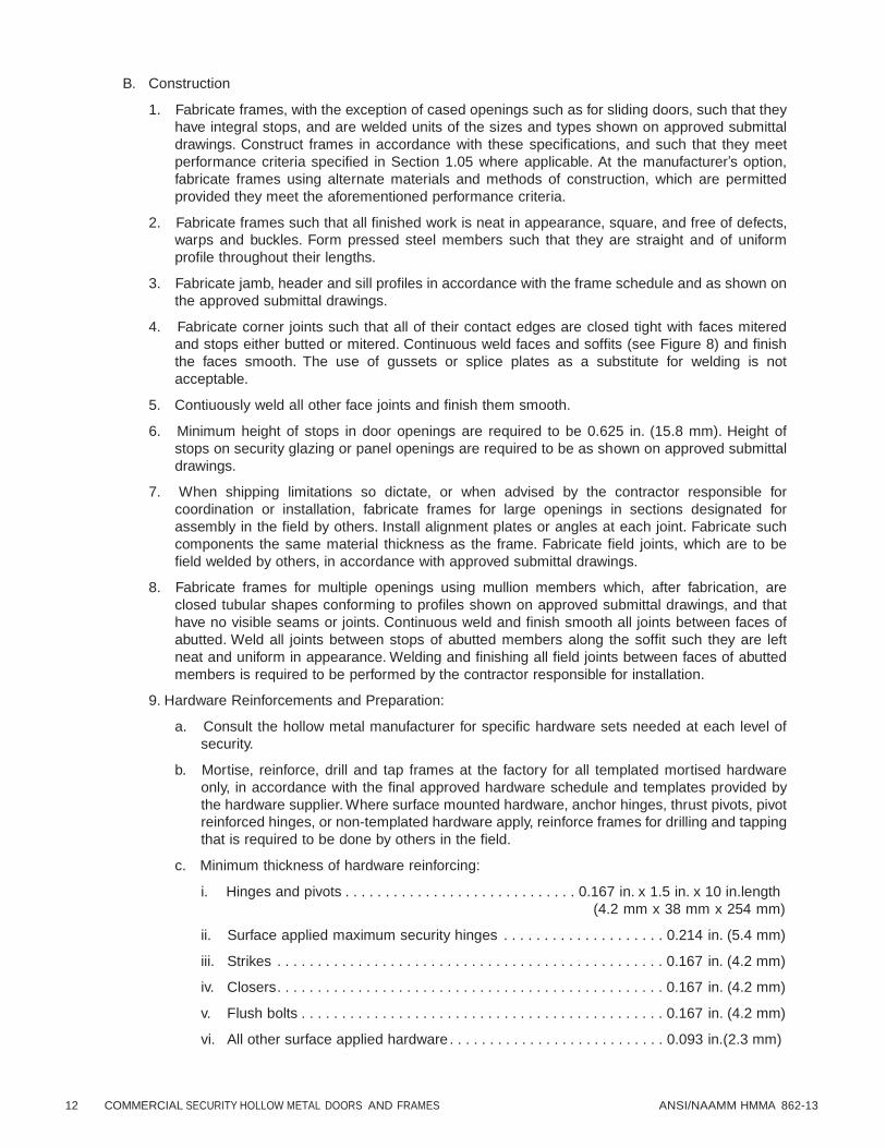
B. Construction
1. Fabricate frames, with the exception of cased openings such as for sliding doors, such that they
have integral stops, and are welded units of the sizes and types shown on approved submittal
drawings. Construct frames in accordance with these specifications, and such that they meet
performance criteria specified in Section 1.05 where applicable. At the manufacturer’s option,
fabricate frames using alternate materials and methods of construction, which are permitted
provided they meet the aforementioned performance criteria.
2. Fabricate frames such that all finished work is neat in appearance, square, and free of defects,
warps and buckles. Form pressed steel members such that they are straight and of uniform
profile throughout their lengths.
3. Fabricate jamb, header and sill profiles in accordance with the frame schedule and as shown on
the approved submittal drawings.
4. Fabricate corner joints such that all of their contact edges are closed tight with faces mitered
and stops either butted or mitered. Continuous weld faces and soffits (see Figure 8) and finish
the faces smooth. The use of gussets or splice plates as a substitute for welding is not
acceptable.
5. Contiuously weld all other face joints and finish them smooth.
6. Minimum height of stops in door openings are required to be 0.625 in. (15.8 mm). Height of
stops on security glazing or panel openings are required to be as shown on approved submittal
drawings.
7. When shipping limitations so dictate, or when advised by the contractor responsible for
coordination or installation, fabricate frames for large openings in sections designated for
assembly in the field by others. Install alignment plates or angles at each joint. Fabricate such
components the same material thickness as the frame. Fabricate field joints, which are to be
field welded by others, in accordance with approved submittal drawings.
8. Fabricate frames for multiple openings using mullion members which, after fabrication, are
closed tubular shapes conforming to profiles shown on approved submittal drawings, and that
have no visible seams or joints. Continuous weld and finish smooth all joints between faces of
abutted. Weld all joints between stops of abutted members along the soffit such they are left
neat and uniform in appearance. Welding and finishing all field joints between faces of abutted
members is required to be performed by the contractor responsible for installation.
9. Hardware Reinforcements and Preparation:
a. Consult the hollow metal manufacturer for specific hardware sets needed at each level of
security.
b. Mortise, reinforce, drill and tap frames at the factory for all templated mortised hardware
only, in accordance with the final approved hardware schedule and templates provided by
the hardware supplier. Where surface mounted hardware, anchor hinges, thrust pivots, pivot
reinforced hinges, or non-templated hardware apply, reinforce frames for drilling and tapping
that is required to be done by others in the field.
c. Minimum thickness of hardware reinforcing:
i. Hinges and pivots . . . . . . . . . . . . . . . . . . . . . . . . . . . . . 0.167 in. x 1.5 in. x 10 in.length
(4.2 mm x 38 mm x 254 mm)
ii. Surface applied maximum security hinges . . . . . . . . . . . . . . . . . . . . 0.214 in. (5.4 mm)
iii. Strikes . . . . . . . . . . . . . . . . . . . . . . . . . . . . . . . . . . . . . . . . . . . . . . . . 0.167 in. (4.2 mm)
iv. Closers. . . . . . . . . . . . . . . . . . . . . . . . . . . . . . . . . . . . . . . . . . . . . . . . 0.167 in. (4.2 mm)
v. Flush bolts . . . . . . . . . . . . . . . . . . . . . . . . . . . . . . . . . . . . . . . . . . . . . 0.167 in. (4.2 mm)
vi. All other surface applied hardware . . . . . . . . . . . . . . . . . . . . . . . . . . . 0.093 in.(2.3 mm)

ANSI/NAAMM HMMA 862-13 COMMERCIAL SECURITY HOLLOW METAL DOORS AND FRAMES 13
d. In cases where electrically or electronically operated hardware is required, and where
indicated on approved hardware schedule, provide hardware enclosures, and/or junction
boxes. Fabricate access plates, where required, of the same material thickness as the frame
and fasten these access plates with not less than four (4) #8-32 tamper resistant machine
screws, not to exceed 6 in. (152 mm) o.c.
10. Floor Anchors:
a. Where applicable, provide floor anchors with two (2) holes for fasteners and fasten them
inside jambs with at least four (4) spot welds per anchor.
b. Where so scheduled, install adjustable floor anchors, that provide not less than 2 in.
(50 mm) height adjustment, and fasten them in place with at least four (4) spot welds per
anchor.
c. Fabricate floor anchors of the same material thickness as frame.
11. Jamb Anchors:
a. Anchor Spacing
Provide the number of anchors on each jamb as follows:
Borrowed light frames: 2 anchors plus 1 for each 18 in. (457 mm) or fraction thereof over 36
in. (914 mm), spaced at 18 in. (457 mm) maximum between anchors
Door frames: 2 anchors plus 1 for each 18 in. (457 mm) or fraction thereof over 54 in. (1372
mm), spaced at 18 in. (457 mm) maximum between anchors (fire ratings can require
additional anchors)
b. Masonry Type
Provide frames for installation in masonry walls with adjustable jamb anchors of the strap
and stirrup type made from the same thickness steel as frame. Fabricate straps such that
they are no less than 2 in. x 10 in. (50.8 mm x 254 mm) in size, corrugated and/or perforated.
c. Embedment Masonry Type
i. Provide frames for installation in pre-finished masonry or concrete openings with
removable faces at the jambs, and 0.167 in. x 2 in. x 2 in. (4.2 mm) x 50.8 mm x 50.8
mm) angle anchors 4 in. (102 mm) long spaced as described in Section 2.03.B.11.a.
Locate the frame anchors to coincide with matching embedded anchors to be provided
for installation in the wall.
ii. Fabricate embedded wall anchors such that they consist of a 0.167 in. (4.2 mm)x 4 in.
(102 mm) wide x 6 in. (152 mm) plate with 0.167 in. x 2 in. x 2 in. (4.2 mm) x 50.8 mm
x 50.8 mm) angle anchors 4 in. (102 mm) long welded in place at locations to match
angle anchors in frames. Provide the embedded plate with two (2) #4 re-bar wall
anchors 10 in. (254 mm) long minimum, with 2 in. (50.8 mm) x 90 degree turn down on
ends continuously welded in place, and spaced as described in Section 2.03.B.10.a.
Prime paint embedments in accordance with Section 2.03.B.14.
iii. Fasten each angle anchor to jamb and to embedded plate with two (2) 1 in. (25.4 mm)
long arc welds at each end of the anchor. Ship anchors separately from the frames.
iv. Anchorage systems that require removable jamb faces are required to be disassembled
in the field by the contractor responsible for installation. The installer is responsible for
shimming at the anchor contact points prior to welding, using steel shims, to assure that
the frame meets installation tolerance requirements specified in Section 3.02.A. The
contractor responsible for installation is required to move the frames into the openings
until the frame anchors contact and match the embedded anchors. The contractor
responsible for installation is required to field weld all anchors and install the jamb faces
in place. Provide embedment anchoring details on approved submittal drawings.
14 COMMERCIAL SECURITY HOLLOW METAL DOORS AND FRAMES ANSI/NAAMM HMMA 862-13
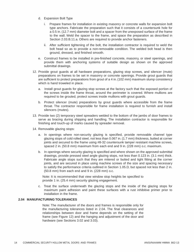
d. Expansion Bolt Type
i. Prepare frames for installation in existing masonry or concrete walls for expansion bolt
type anchors. Fabricate the preparation such that it consists of a countersunk hole for
a 0.5 in. (12.7 mm) diameter bolt and a spacer from the unexposed surface of the frame
to the wall. Weld the spacer to the frame, and space the preparation as described in
Section 2.03.B.11.a. Others are required to provide anchor fasteners.
ii. After sufficient tightening of the bolt, the installation contractor is required to weld the
bolt head so as to provide a non-removable condition. The welded bolt head is then
ground, dressed, and finished smooth.
e. Construct frames to be installed in pre-finished concrete, masonry, or steel openings, and
provide them with anchoring systems of suitable design as shown on the approved
submittal drawings.
12. Provide grout guards at all hardware preparations, glazing stop screws, and silencer (mute)
preparations on frames to be set in masonry or concrete openings. Provide grout guards that
are sufficient to protect preparations from grout of a 4 in. (102 mm) maximum slump consistency
which is hand troweled in place.
a. Install grout guards for glazing stop screws at the factory such that the exposed portion of
the screws inside the frame throat, around the perimeter is covered. Where mullions are
required to be grouted, protect screws inside mullions with grout guards.
b. Protect silencer (mute) preparations by grout guards where accessible from the frame
throat. The contractor responsible for frame installation is required to furnish and install
silencers (mutes).
13. Provide two (2) temporary steel spreaders welded to the bottom of the jambs of door frames to
serve as bracing during shipping and handling. The installation contractor is responsible for
finishing and touch-up of marks caused by spreader removal.
14. Removable glazing stops:
a. In openings where non-security glazing is specified, provide removable channel type
glazing stops of cold rolled steel, not less than 0.067 in. (1.7 mm) thickness, butted at corner
joints and secured to the frame using #8-32 countersunk tamper resistant machine screws,
spaced 2 in. (50.8 mm) maximum from each end and 9 in. (228 mm) o.c. maximum.
b. In openings where security glazing is specified and where shown on the approved submittal
drawings, provide pressed steel angle glazing stops, not less than 0.123 in. (3.1 mm) thick.
Fabricate angle stops such that they are mitered or butted and tight fitting at the corner
joints, and are secured in place using machine screws of the size and spacing necessary
to satisfy the performance criteria outlined in Section 1.05.D, but spaced not less than 2 in.
(50.8 mm) from each end and 9 in. (228 mm) o.c.
Note: It is recommended that view window stop heights be specified to
provide 1 in. (25.4 mm) security glazing engagement.
c. Treat the surface underneath the glazing stops and the inside of the glazing stops for
maximum paint adhesion and paint these surfaces with a rust inhibitive primer prior to
installation in the frame.
2.04 MANUFACTURING TOLERANCES
Note: The manufacturer of the doors and frames is responsible only for
the manufacturing tolerances listed in 2.04. The final clearances and
relationships between door and frame depends on the setting of the
frame (see Figure 12) and the hanging and adjustment of the door and
hardware (see Sections 3.02 and 3.03).

ANSI/NAAMM HMMA 862-13 COMMERCIAL SECURITY HOLLOW METAL DOORS AND FRAMES 15
A. Maintain manufacturing tolerance within the following limits:
1. Frames for single door or pair of doors:
a. Width, measured between rabbets at the head: Nominal opening width + 1/16 in. (1.5 mm),
- 1/32 in. (0.8 mm)
b. Height (total length of jamb rabbet): Nominal opening height + 1/16 in. (1.5 mm), - 1/32 in.
(0.8 mm).
2. Cross sectional frame profile dimensions: (see Figure 9)
a. Face . . . . . . . . . . . . . . . . . . . . . . . . . . . . . . . . . . . . . . . . . . . . . . . . . . . . ± 1/32 in. (0.8 mm)
b. Stop . . . . . . . . . . . . . . . . . . . . . . . . . . . . . . . . . . . . . . . . . . . . . . . . . . . . . ± 1/32 in. (0.8 mm)
c. Rabbet. . . . . . . . . . . . . . . . . . . . . . . . . . . . . . . . . . . . . . . . . . . . . . . . . . . ± 1/32 in. (0.8 mm)
d. Depth . . . . . . . . . . . . . . . . . . . . . . . . . . . . . . . . . . . . . . . . . . . . . . . . . . +/- 1/16 in. (1.5 mm)
e. Throat . . . . . . . . . . . . . . . . . . . . . . . . . . . . . . . . . . . . . . . . . . . . . . . . . . +/- 3/32 in. (2.3 mm)
Note: Frames overlapping walls to have throat dimension 1/8 in. (3.1
mm) greater than dimensioned wall thickness to accommodate
irregularities in wall construction.
3. Flatness of large frames: 1/8 in (3.1 mm) in 10 ft (3048 mm) of length or width
4. Doors - Doors are undersized to fit the frame. Edge clearances are based upon individual door
manufacturer’s designs. Tolerance on actual door sizes are as follows:
a. Width . . . . . . . . . . . . . . . . . . . . . . . . . . . . . . . . . . . . . . . . . . . . . . . . . . . . ± 3/64 in.(1.2 mm)
b. Height. . . . . . . . . . . . . . . . . . . . . . . . . . . . . . . . . . . . . . . . . . . . . . . . . . . . ± 3/64 in.(1.2 mm)
c. Thickness . . . . . . . . . . . . . . . . . . . . . . . . . . . . . . . . . . . . . . . . . . . . . . . . . ± 1/16 in.(1.5 mm)
d. Edge Flatness . . . . . . . . . . . . . . . . . . . . . . . . . . . . . . . . . . . . ± 1/16 in. (1.5 mm) maximum
e. Surface Flatness . . . . . . . . . . . . . . . . . . . . . . . . . . . . . . . . . . . . ± 1/8 in.(3.2 mm) maximum
5. Hardware
a. Cutout and template dimensions . . . . . . . . . . . . . . . . . . . . . . . . . . + 0.015 in.(0.38 mm), - 0
b. Location . . . . . . . . . . . . . . . . . . . . . . . . . . . . . . . . . . . . . . . . . . . . . . . . . . ± 1/32 in.(0.8 mm)
c. Between hinge centerlines. . . . . . . . . . . . . . . . . . . . . . . . . . . . . . . . . . . . ± 1/64 in.(0.4 mm)
2.05 HARDWARE LOCATIONS
Locate hardware on doors and frames as listed below. All dimensions except the hinge locations are
referenced from the floor as defined in Section 3.03.
When security hollow metal frames are specified for use with doors to be furnished by others, hardware
preparations on the doors are normally governed by the location on the frames as stated in 2.05.A.
A. Hinges: Top 5 in.(127 mm) from underside of frame head rabbet at door opening to top of hinge
Bottom . . . . . . . . . . . . . . . . . . . . . . . . 10 in.(254 mm) from finished floor to bottom of hinge
Intermediate . . . . . . . . . . . . . . . . . . . . . . . . . . . . Centered between top and bottom hinges
B. Locks and latches. . . . . . . . . . . . . . . . . . . . . . . . 38 in.(965 mm) to centerline of knob or lever shaft
C. Deadlocks 46 in.(1168 mm) to centerline of cylinder
D. Exit hardware . . . . . . 38 in.(965 mm) to centerline of cross bar or as shown on hardware template
E. Door pulls 42 in.(1066 mm) to centerline of grip
F. Push/pull bars . . . . . . . . . . . . . . . . . . . . . . . . . . . . . . . . . . . . . . 42 in.(1066 mm) to centerline of bar
16 COMMERCIAL SECURITY HOLLOW METAL DOORS AND FRAMES ANSI/NAAMM HMMA 862-13
G. Arm pulls . . . . . . . . . . . . . . . . . . . . . . . . . . . . . . . . . . . . . . . . . . . . . 46 in.(1168 mm) to centerline
H. Push plates . . . . . . . . . . . . . . . . . . . . . . . . . . . . . . . . . . . . . . 46 in.(1168 mm) to centerline of plate
I. Intercoms . . . . . . . . . . . . . . . . . . . . . . . . . 48 in.(1219 mm) to centerline of intercom push button
See NAAMM / HMMA 830 and 831 for additional information.
2.06 FINISH
A. After fabrication, fill and sand all tool marks and surface imperfections as required to make face
sheets, vertical edges and weld joints free from irregularities.
B. After appropriate metal preparation, apply a rust inhibitive primer, which meets or exceeds the
performance requirements of Section 1.05.F, to all exposed surfaces of doors and frames. For
stainless steel finishes, refer to ANSI/NAAMM/HMMA 866.
C. Primer must be fully cured prior to shipment.
All primer and finish paint must be formulated for Direct to Metal (DTM)
application.
PART 3 – EXECUTION
Proper storage and protection is essential to the proper performance of
doors and frames. The requirements for proper storage are given in the
following sections. However, it is important to recognize that proper
storage is not the responsibility of the commercial security hollow metal
manufacturer. For this reason, the requirements for storage and
protection of detention hollow metal doors and frames should be
included in that section of the specifications where installation of work is
specified. For additional information regarding installation, see NAAMM
/ HMMA 840, “Guide Specifications for Installation and Storage of
Hollow Metal Doors and Frames”. (Reference: HMMA 840 “Installation
and Storage of Hollow Metal Doors and Frames”).
3.01 SITE STORAGE AND PROTECTION OF MATERIALS
A. The contractor responsible for installation is required to remove wraps or covers from doors and
frames upon delivery at the building site and to ensure that any scratches or disfigurement caused
in shipping or handling are promptly sanded smooth, cleaned and touched up with a compatible rust
inhibitive primer.
B. The contractor responsible for installation is required to ensure that materials are properly stored on
planks or dunnage in a dry location. Doors are required to be stored in a vertical position and spaced
by blocking. Figure 10 illustrates recommended storage positioning. Materials are required to be
covered to protect them from damage but in such a manner as to permit air circulation.
3.02 INSTALLATION
Correct installation is essential to the proper performance of detention
doors and frames. The requirements for proper installation are given in
the following sections. However, it is important to recognize that
installation is not the responsibility of the detention hollow metal
manufacturer. For this reason, the requirements for installation of
detention hollow metal doors and frames should be included in that
section of the specifications where installation of work is specified. It is
the responsibility of the general contractor using experienced personnel
to perform the work outlined in this section. For additional information
regarding installation, see NAAMM / HMMA 840, “Guide Specifications
for Installation and Storage of Hollow Metal Doors and Frames”.
(Reference: HMMA 840 “Installation and Storage of Hollow Metal Doors
and Frames”).

ANSI/NAAMM HMMA 862-13 COMMERCIAL SECURITY HOLLOW METAL DOORS AND FRAMES 17
A. Th
1.
e installer is required to perform the following:
Prior to installation, check the area of floor on which the frame product is to be installed, and
within the path of the door swing, for flatness.
2. Prior to installation, remove temporary spreaders. Check doors and frame product for correct
size, swing, fire rating and opening number.
3. Prior to installation, isolate and protect all interior surfaces of perimeter frame product sections
to be installed in masonry or concrete walls from grout and antifreeze agents.
The drawbacks and benefits associated with the use of water based
masonry grouts, with or without antifreeze agents, should be carefully
weighed during the detailing and specification process. Grouting of
mullions and other closed sections is not recommended, and plaster
based grouts should not be used. Refer to NAAMM HMMA Tech Note,
HMMA 820 TN01-03, “Grouting Hollow Metal Frames”, included as
Appendix 2, for further guidance.
4. During the setting of frame product check and correct as necessary for opening width, opening
height, squareness, alignment, twist and plumbness. Maintain installation tolerances within the
following limits.
a. Opening Width . . . . . . . . . . . . . . . . . . . . . .measured from rabbet to rabbet at top, middle
and bottom of frame + 1/16 in (1.5 mm) – 1/32 in
(0.8 mm)
b. Opening Height . . . . . . . . . . . . . . . . . . . . .measured vertically between the frame head
rabbet and top of floor or bottom of frame minus
jamb extensions at each jamb and across the
head: + 1/16 in (1.5 mm) – 1/32 in (0.8 mm)
c. Squareness . . . . . . . . . . . . . . . . . . . . . . . .measured at rabbet on a line from jamb,
perpendicular to frame head; not to exceed 1/16
in (1.5 mm)
d. Alignment . . . . . . . . . . . . . . . . . . . . . . . . . .measured at jambs on a horizontal line parallel
to the plane of the face; not to exceed 1/16 in
(1.5 mm)
e. Twist . . . . . . . . . . . . . . . . . . . . . . . . . . . . . .measured at opposite face corners of jambs on
parallel lines perpendicular to the plane of the
door rabbet; not to exceed 1/16 in (1.5 mm)
f. Plumbness . . . . . . . . . . . . . . . . . . . . . . . . .measured at the jambs on a perpendicular line
from the head to the floor; not to exceed 1/16 in
(1.5 mm)
The above tolerances provide a reasonable guideline for proper installation of hollow metal
frame product. However, it should be noted that the cumulative affect of the installation
tolerances at or near their maximum levels could result in sufficient misalignment to prevent the
door from functioning properly. Installers should be careful not to create a tolerance buildup.
Tolerance buildup occurs when several tolerances are at or near their maximums.
5. The details in Figure 3 illustrate the method of measuring the above specified tolerances.
6. Grout guards and junction boxes are intended to protect hardware mortises and tapped holes
from masonry grout of 4 in. (101 mm) maximum slump consistency which is hand troweled in
place. If a lighter consistency grout (greater than 4 in. (101 mm) slump when tested in
accordance with ASTM C 143/C 143M) is to be used, special precautions must be taken in the
field by the installer to protect the aforementioned.

18 COMMERCIAL SECURITY HOLLOW METAL DOORS AND FRAMES ANSI/NAAMM HMMA 862-13
7. Frame products are not intended or designed to act as forms for grout or concrete. Grouting of
hollow metal sections are required to be done in “lifts” or precautions otherwise taken by the
contractor to ensure that frames are not deformed or damaged by the hydraulic forces that occur
during this process.
8. Keep hollow metal surfaces free of grout, tar and/or other bonding materials or sealers. Promptly
clean off grout, tar, and/or bonding materials or sealers from frame product and doors.
9. Finish and touch-up marks caused by spreader removal.
10. Promptly finish smooth, clean, treat for maximum paint adhesion, and touch up with a rust
inhibitive primer all exposed hollow metal surfaces which have been scratched or otherwise
marred during installation, cleaning, and/or field welding. Use a primer that is comparable to and
compatible with the shop applied primer and finish paint specified in Section 09 90 00 [09900].
All touch-up primer and finish paint must be formulated for Direct to Metal (DTM) application.
11. Install labeled fire doors and frame product in accordance with the terms of their listings,
ANSI/NFPA 80, or the local Authority Having Jurisdiction.
12. Proper door edge clearances must be maintained in accordance with Section 3.03, except for
special conditions otherwise noted. Where necessary, metal hinge shims, furnished by installer,
are permitted to maintain clearances.
13. Apply hardware in accordance with hardware manufacturer’s templates and instructions.
14. Finish paint in accordance with Section 09 90 00 [09900].
15. Install door silencers (mutes).
16. Install glazing materials in accordance with Section 08 80 00 [08800].
3.03. CLEARANCES
A. Edge clearance for swinging hollow metal doors are required to be a minimum of 1/32 in (0.8 mm)
in order to provide for the functional operation of the assembly and are required to not exceed the
following:
1. Between doors and frame product at head and jambs . . . . . . . . . . . . . . . . . . 3/16 in. (4.7 mm)
2. Between edges of pairs of doors . . . . . . . . . . . . . . . . . . . . . . . . . . . . . . . . . . . 3/16 in. (4.7 mm)
Edge clearance for labeled fire doors and frames is covered by
3.02.A.11.
B. Floor clearance for swinging hollow metal doors are required to not exceed the following:
1. At bottom of door where threshold in used . . . . . . . . . . . . . . . . . . . . . . . . 3/8 in. (9.5 mm) from
bottom of door to top of
threshold
2. At bottom of door where no threshold is used. . . . . . . . . . . . . . . . 3/4 in. (19.1 mm) above floor
3. Between bottom of door and nominal surface of
floor coverings at fire-rated openings, as provided
in ANSI/NFPA 80 . . . . . . . . . . . . . . . . . . . . . . . . . . . . . . . . . . . . . . . . . . . . . . . 1/2 in. (12.7 mm)
The architect must define the distance from top of the floor/finished floor
to top of floor covering so appropriate undercuts can be provided.
Floor/Finish Floor is defined as the top of the concrete or structural slab.
HMMA uses the term “top of floor covering” to describe the NFPA term
“nominal surface of floor covering.” Refer to HMMA’s Tech Note, HMMA
810 TN01-03, “Defining Undercuts,” included as Appendix 3 for further
guidance.

SECURITY
RATING
FORCED ENTRY
STATIC LOAD
IMPACT
EDGE CRUSH
JAMB/WALL
STIFFNESS
C L A S S I F I C A T I O N
T O O L
C A T E G O R Y
TEST
LEVEL
SPECIFICATION
IN
MINUTES
A P C E T R I S V O E N
N T E E L S T
INDIVIDUAL
SYSTEMS
MULLED
SYSTEMS
DOUBLE DOOR
SYSTEMS
AT CORNER
POINTS
BETWEEN
LOCK POINTS
AT LOCK
POINTS
AT
H P I O N I G N E T
S
AT
L P O O C I K N
T S
AT
M S U Y L S L T E E D M
S
AT
G P L O A I Z N I T N S G
AT DOOR EDGE
JAMB TO JAMB
SPREAD
RESISTANCE
MOST
V U O L C N A E T R I A O B N L S E
S L E O L C E A C T T I E O D N
S
E A C H
M U L L
I O N
SEAMS
B D E O T O W R E S E N
HINGE
OF
A D C O T O I R V E
HINGE
OF
I D N O A O C R T I V E
S L E O L C E A C T T I E O D N
S
L O A D
M D A E X F I L M E U C M T
I O N
L O A D
M D A E X F I L M E U C M T
I O N
L O A D
M D A E X F I L M E U C M T
I O N
L O A D
M D A E X F I L M E U C M T
I O N
MAXIMUM
LOAD
WITHOUT
COLLAPSE
L O A D
M D A E X F I L M E U C M T
I O N
lbf
(kn)
IN
(mm)
lbf
(kn)
IN
(mm)
lbf
(kn)
IN
(mm)
FT lbf
(J)
FT lbf
(J)
FT lbf
(J)
FT lbf
(J)
lbf
(kn)
IN
(mm)
lbf
(kn)
lbf
(kn)
IN
(mm)
1
A
5
2
5
5
5
5
5
5
5
662
(1.5)
1.181
(30)
662
(1.5)
1.181
(30)
1325
(3)
.394
(10)
CLASSES 1 - 2 - 3 USE
SOFT BODY IMPACTING
1325
(3)
.25
(6.4)
2000
(4.5)
1350
(3.1)
.375
(9.5) 2 BLOWS
@ 59
(80)
2 BLOWS
@ 59
(80)
2 BLOWS
@ 59
(80)
2 BLOWS
@ 59
(80)
TEST METHOD
PARAGRAPH
2
B
10
4
10
10
10
10
10
10
10
662
(1.5)
1.181
(30)
662
(1.5)
1.181
(30)
1325
(3)
.394
(10)
CLASS 1+
2 BLOWS
@ 89
(120)
CLASS 1+
2 BLOWS
@ 89
(120)
CLASS 1+
2 BLOWS
@ 89
(120)
CLASS 1+
2 BLOWS
@ 89
(120)
1325
(3)
.25
(6.4)
2000
(4.5)
1850
(4.1)
.375
(9.5)
TEST METHOD
PARAGRAPH
3
C
15
6
15
15
15
15
15
15
15
1325
(3)
.787
(20)
1325
(3)
.787
(20)
2645
(6)
.394
(10)
CLASS 2+
2 BLOWS
@ 118
(160)
CLASS 2+
2 BLOWS
@ 118
(160)
CLASS 2+
2 BLOWS
@ 118
(160)
CLASS 2+
2 BLOWS
@ 118
(160)
1985
(4.5)
.25
(6.4)
4000
(9)
3600
(8.2)
.50
(13)
TEST METHOD
PARAGRAPH
4
D
20
6
20
20
20
20
20
20
20
2645
(6)
.394
(10)
2645
(6)
.394
(10)
4410
(10)
.394
(10)
CLASSES 4 - 5 - 6 USE
HARD BODY IMPACTING
3500
(7.9)
.25
(6.4)
6000
(13.6)
4950
(11.2)
.50
(13) 30 BLOWS
@ 148
(200)
100 BLOWS
@ 148
(200)
30 BLOWS
@ 148
(200)
30 BLOWS
@ 148
(200)
TEST METHOD
PARAGRAPH
5
E
40
6
40
40
40
40
40
40
40
4410
(10)
.394
(10)
4410
(10)
.394
(10)
6615
(15)
.394
(10)
CLASS 4+
75 BLOWS
@ 200
(271.2)
CLASS 4+
200 BLOWS
@ 200
(271.2)
CLASS 4+
30 BLOWS
@ 200
(271.2)
CLASS 4+
30 BLOWS
@ 200
(271.2)
5750
(13)
.25
(6.4)
10000
(22.7)
6000
(13.6)
.50
(13)
TEST METHOD
PARAGRAPH
6
F
60
6
60
60
60
60
60
60
60
4410
(10)
.394
(10)
4410
(10)
.394
(10)
6615
(15)
.394
(10)
CLASS 5+
100 BLOWS
@ 200
(271.2)
CLASS 5+
300 BLOWS
@ 200
(271.2)
CLASS 5+
30 BLOWS
@ 200
(271.2)
CLASS 5+
30 BLOWS
@ 200
(271.2)
8000
(18.1)
.25
(6.4)
15000
(34)
7500
(17)
.50
(13)
TEST METHOD
PARAGRAPH
AN
SI/N
AA
MM
HM
MA
86
2-X
X
CO
MM
ER
CIA
L S
EC
UR
ITY
HO
LL
OW
ME
TA
L D
OO
RS
AN
D F
RA
ME
S
19
Table 1
L

20 COMMERCIAL SECURITY HOLLOW METAL DOORS AND FRAMES ANSI/NAAMM HMMA 862-13
C8 X 13.75
STEEL CHANNEL (TYPICAL)
#4 REBAR
(TYPICAL)
16IN.
(406 MM . )
120 I N.
(3048 MM )
50 I N.
(1270 MM . )
16 IN.
(406 MM . )
32 I N.
(812.8 MM . ) 50 I N.
(1270 MM . )
114 IN.
(2896 MM . )
32 I N. (812.8 MM . )
C8 X 13.75
STEEL CHANNEL (TYPICAL)
15 IN. ( 381 MM . )
#4 REBAR
(TYPICAL)
120 I N
(3048 MM . )
32 I N.
(813 MM . )
40 I N.
(1015 MM . )
32 I N.
(813 MM . )
45 IN.
(1143 MM . )
32 I N.
(813 MM . )
BRACE AGAINST
COLUMN OR WALL
CENTER SUPPORT
FOR WALL
52 I N.
(1320.8 MM . )
DROP
HEIGHT
BRACE AT
CENTER COLUMN
STEEL ANGLE
BRACING TYPICAL
IMPACT RAM 60 I N.
(1524 MM . )
ANCHOR TO FLOOR
AT CORNERS
40 I N.
(1016 MM . )
40 I N.
(1016 MM . )
40 I N.
(1016 MM . )
FIGURE 1Test Wall

ANSI/NAAMM HMMA 862-13 COMMERCIAL SECURITY HOLLOW METAL DOORS AND FRAMES 21
DIS
PL
AC
EM
EN
T
1 1/2"
(38.1 MM)
FR =max
DOOR
DOOR
13/16"
(20.6 MM)
13/16"
(20.6 MM)
BEFORE LOADI NG AFTER LOADI NG FOR
1 MI NUTE AT FR=MAX
MEASURE MENT OF DISPLACEM ENT
HINGE SIDE
DOOR LOAD POINTS
DOOR
FRAME
LOCK SIDE
FIGURE 2
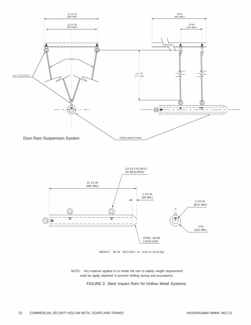
22 COMMERCIAL SECURITY HOLLOW METAL DOORS AND FRAMES ANSI/NAAMM HMMA 862-13
25 1/4 IN.
(641 MM.)
23 1/2 IN.
(597 MM.)
38 IN.
(965 MM.)
10 IN.
(254 MM.)
Door Ram Suspension System STEEL IMPACT RAM
1/2-13 EYE-BOLT
AS REQUIRED
31 1/2 IN.
(800 MM.)
1 1/2 IN.
(38 MM.)
2 1/4 IN.
(63.5 MM.)
4 IN.
(102 MM.)
STEEL NOSE
C1010-1020
WEIGHT: 80 LB (36.3 KG) + or - 0.25 Lb. (0.10 Kg)
NOTE: Any material applied to or inside the ram to satisfy weight requirement
shall be rigidly attached to prevent shifting during test procedures.
FIGURE 3 Steel Impact Ram for Hollow Metal Systems

ANSI/NAAMM HMMA 862-13 COMMERCIAL SECURITY HOLLOW METAL DOORS AND FRAMES 23

24 COMMERCIAL SECURITY HOLLOW METAL DOORS AND FRAMES ANSI/NAAMM HMMA 862-13

ANSI/NAAMM HMMA 862-13 COMMERCIAL SECURITY HOLLOW METAL DOORS AND FRAMES 25

26 COMMERCIAL SECURITY HOLLOW METAL DOORS AND FRAMES ANSI/NAAMM HMMA 862-13

ANSI/NAAMM HMMA 862-13 COMMERCIAL SECURITY HOLLOW METAL DOORS AND FRAMES 27
SPACER
HYDRAULIC RAM
LOAD CELL
DIAL INDI CATOR
HINGE
JAMB
STRIKE
JAMB
DOOR DOOR
(38.1 x 127 x 3.2 MM.)
1 1/2" x 5" x 1/ 8"
PLATES (TYP. )
DOOR
FRAME
HINGE SIDE DIAL INDICATOR BASE OF DOOR FACE.
LOCK SIDE
HYDRAULIC RAM
LOAD CELL
FIGURE 6
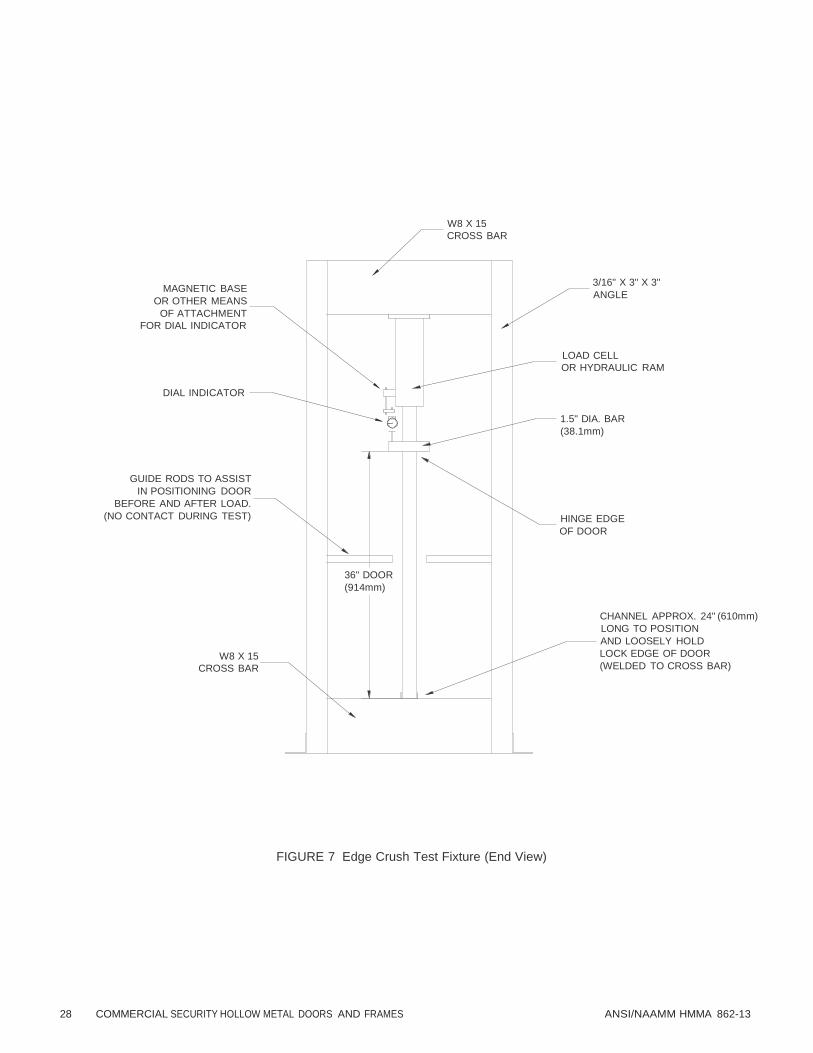
28 COMMERCIAL SECURITY HOLLOW METAL DOORS AND FRAMES ANSI/NAAMM HMMA 862-13
W8 X 15
CROSS BAR
MAGNETIC BASE
OR OTHER MEANS
OF ATTACHMENT
FOR DIAL INDICATOR
3/16" X 3" X 3"
ANGLE
LOAD CELL
OR HYDRAULIC RAM
DIAL INDICATOR
1.5" DIA. BAR
(38.1mm)
GUIDE RODS TO ASSIST
IN POSITIONING DOOR
BEFORE AND AFTER LOAD.
(NO CONTACT DURING TEST)
HINGE EDGE
OF DOOR
36" DOOR
(914mm)
W8 X 15
CROSS BAR
CHANNEL APPROX. 24" (610mm)
LONG TO POSITION
AND LOOSELY HOLD
LOCK EDGE OF DOOR
(WELDED TO CROSS BAR)
FIGURE 7 Edge Crush Test Fixture (End View)

ANSI/NAAMM HMMA 862-13 COMMERCIAL SECURITY HOLLOW METAL DOORS AND FRAMES 29
X1. GUIDELINES FOR USE
X1.1 FORCED ENTRY AND BALLISTICS RESISTANCE OF WINDOWS, DOORS, AND NON-WINDOW
OPENINGS
X1.1.1 This standard was developed to provide architects and owners the background and guidance to
specify the security performance and testing requirements of building envelope elements based upon
the level of security required for each opening, and considering two (2) criteria, Forced Entry Resistance
and Ballistics Resistance. There are many other aspects of physical security, however, this standard
addresses only these two considerations.
X1.1.2 Forced Entry and Ballistic Resistant (FEBR) doors, windows, sidelight and multiple light glazed
systems should be specified and tested under ANSI/NAAMM/HMMA-862, “Guide Specifications for
Commercial Security Hollow Metal Doors and Frames”. Although HMMA-862 is written to address doors
and glazed openings, the testing that is described throughout and summarized in Table 1, particularly
the forced entry testing and the ballistics testing, is readily adaptable and routinely performed on other
exterior opening protectives, such as, Deal Trays, Pass Drawers, HVAC louvers, grilles, and roof
hatches.
X1.1.3 There are six (6) Security Rating Classifications, 1 being the lowest or least secure, and 6 being
the highest rating. Levels 3 through 6, which include forced entry requirements of 15 minutes through
60 minutes, respectively, are typically considered the levels that are most applicable to Homeland
Security Applications.
X1.1.4 There are tests described by this specification which are conducted in accordance with; SD-STD-
01.01, Revision G, 1993; “Certification Standard on Forced Entry and Ballistic Resistance of Structural
Systems”; UL Standard 752, “Bullet Resisting Equipment”; and LPS 1175; Issue 5 (2000), “Specification
for Testing and Classifying the Burglary Resistance of Building Components, Strong Points and Security
Enclosures”, ASTM F1450, “Test Methods for Hollow Metal Swinging Door Assemblies for Detention
Facilities”, and ASTM F1592, “Test Methods for Detention Locks for Swinging Doors”. These tests are
typically conducted using test sample sizes that represent actual field applications. For example, door
sizes are typically 3 ft. 0 in. wide X 7 ft. 0 in. high (914 mm X 2133 mm). Brief descriptions of the tests
are as follows:
1) Bullet resistance tests
2) Door static load test
3) Door assembly impact testing
Soft body impact attack test Class 1, 2, 3
Hard body impact attack test Class 4, 5, 6
4) Removable glazing stop test for vision systems
5) Forced entry
6) Jamb/wall stiffness test
7) Edge crush test
X1.1.5 The bullet resistance test is conducted in accordance with UL Standard 752 or SD-STD-01.01,
Rev. G. These standards cover bullets fired from various calibers of handguns up to high-powered rifles
using armor-piercing ammunition, typically the military rounds 5.56 mm and 7.62 mm. “Bullet resisting”
signifies protection against complete penetration, passage of fragments of projectiles, or spalling
(fragmentation) of the protective material to the degree that injury would be caused to a person standing
directly behind the bullet resisting barrier.
X1.1.6 Under the static load test, a door complete with hardware is mounted in its frame with the entire
assembly in the vertical position so that the door and locking elements are operable. The assembly is
then subjected to a series of static loads. The test performance standard requires that the door not
exceed a specified maximum deflection when a specified load is applied.
X1.1.7 The impact test, conducted in accordance with ASTM F1450 and ASTM F1592, provides a
realistic measure of an assembly’s ability to withstand the punishment it can receive under attempted

30 COMMERCIAL SECURITY HOLLOW METAL DOORS AND FRAMES ANSI/NAAMM HMMA 862-13
forced entry using ramming techniques. ASTM F1450 and F1592 were first published in 1991 and 1995,
respectively. Both of these test methods have good track records with regard to suitability for the
applications, or “severity,” and repeatability from one laboratory to another. Testing under these
standards provides a good “base-line” performance evaluation of product design, strengths of materials,
impact fatigue strength of the assembly, and quality of manufacturing. Basically, the assembly is
subjected to a series of impacts using either of the following:
• A soft body ram, which simulates a person using a shoulder or kick attack to gain entry, or
• A hard body ram, which simulates a person using a sledge hammer, or more than one person using
a ramming implement to gain entry.
X1.1.8 The removable glazing stops test is also done with impact loads. Its purpose is to assure that the
glazing stops used in the frame, when fastened in place, are at least equal to the strength of the security
glazing they support.
X1.1.9 The jamb/wall stiffness test gauges the frame assembly’s ability to withstand prying pressure
apparent when trying to disengage the lock bolt from the strike.
X1.1.10 The edge crush test gauges the door’s ability to withstand prying pressure apparent when trying
to disengage the lock bolt from the frame.
X1.1.11 The forced entry attack tests consists of a “real world” battery of tests where a testing team
actually attacks the face of the assembly and the hinge and locking elements using a host of tools and
equipment in accordance with the rating classification required, and the test is conducted for a
prescribed time period on each element of the assembly.
X1.1.11.1 With regard to Table 1, the Forced Entry columns, security ratings 1 – 6 (rated in minutes
ranging from 5 to 60 minutes) refer to testing procedures set forth by either the Loss Prevention
Standard LPS 1175 issue 5 (2000) or the SD-STD-01.01, Rev G, certification standard for Forced Entry.
X1.1.11.2 Forced Entry testing procedures under the U.S. Department of State (DOS) standard, SD-
STD-01.01, Rev.G, call for a “concentrated assault” on edges, seams and other predicted vulnerable
locations on the test sample, and in accordance with direction from the test director. The attack team
consists of six (6) people of specified range of size, condition and age. The standard provides for one
set of tools available to the attack team, which are listed in Table 2, and by policy, DOS has established
three (3) classifications, 5, 15 and 60 minute, corresponding to security ratings 1, 2, and 6 from Table 1.
Forced Entry ratings of 15 and 60 minutes include Bullet Resistance testing conducted on the test
sample prior to the timed forced entry attempt. Bullet resistance testing is not required for the 5 minute
classification.
X1.1.11.3 Forced Entry procedures conducted under the Loss Prevention Council standard, LPS-1175,
call for “manual intervention” on building components, strong points and enclosures, again, employing
an attack team operating under the direction of a test director. The LPS standard has established six (6)
classifications, each classification requiring attacks to be conducted over incrementally increasing time
periods, 5 minutes through 60 minutes, corresponding to security ratings 1 through 6. The number and
capabilities of the tools available to the attack team are incrementally upgraded as one moves up the
scale such that there are six (6) “Tool Categories”, A through F, corresponding to the six (6) security
ratings. Security grade 1 calls for Tool Category A, 2 calls for B, and so on. These Tool Categories are
listed in Table 3. The attack team consists of two (2) people for rating #1, four (4) for rating #2, and six
(6) for ratings #3 through #6. There is no bullet resistance testing incorporated into LPS 1175.
X1.1.11.4 Although, the forced entry testing procedures under LPS-1175 and SD-STD-01.01 vary with
regard to personnel, tools and bullet resistance considerations, both have generally been considered
comparable within the security products and systems industry and certifications under either have been
considered acceptable.
X1.1.12 End users may pick and choose from Table 1 higher or lower level procedures to accomplish
their needs.
X1.1.12.1 For example, a buyer may specify Level 6 for Static Load, Impact, Edge Crush and Jamb/Wall
Stiffness because the primary concern is burglary resistance, and elect to choose only Level 1 Forced

ANSI/NAAMM HMMA 862-13 COMMERCIAL SECURITY HOLLOW METAL DOORS AND FRAMES 31
Entry because resistance to attacks of higher levels of sophistication is of low probability, thus low
priority. Typically, there is considerable cost difference as one moves up the scale with regard to FEBR
ratings, therefore, buyers can use Table 1 to structure their performance requirements to best suit their
priorities and at the same time, obtain the best economy. Table 1 is included as part of this Appendix.
X1.1.12.2 Another common example is the case of a buyer who requires a Forced Entry rating of level
3 (15 min) or level 6 (60 min); a Ballistics Resistance rating of 7.62 mm and 5.56 mm (Included in Forced
Entry testing from levels 3 – 6), but does not require the other testing shown in Table 1. These levels of
Forced Entry are typically specified for high risk openings where substantial resistance to attacks of
higher levels of sophistication is a high priority. In such a case, the manufacturer or supplier again should
be required to submit documentation showing that testing conducted by an independent testing
laboratory was completed in accordance with the specified test standards, and are also required to
submit certifications from the Loss Prevention Council (LPC) or the U.S. Department of State (DOS)
stating that the product provided is 15 minute or 60 minute rated, including associated ballistics
resistance.
X1.1.13 Fire Testing: Where openings require fire ratings and where fire ratings are specified by the
contract documents of the building project, protective assemblies for those openings, such as, doors,
frames, borrowed lights and side-lights are fire tested in accordance with test method UL-10C or NFPA
252. Windows are tested in accordance with UL-9C or NFPA-257. The pass/fail criteria and criteria for
assignment of fire ratings are in accordance with the applicable test methods. The manufacturers of
rated or listed products maintain their product listings and manufacturing procedures under the auspices
of the fire testing laboratory, such as, Underwriters’ Laboratories (UL) or Intertek Testing Services (ITS).
Information regarding available fire rated FEBR products is typically available from the laboratories
through their websites and through their Building Materials Directories.
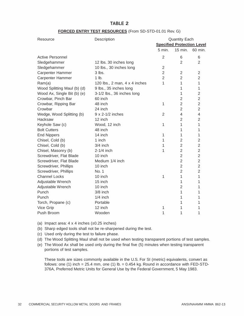
32 COMMERCIAL SECURITY HOLLOW METAL DOORS AND FRAMES ANSI/NAAMM HMMA 862-13
TABLE 2
FORCED ENTRY TEST RESOURCES (From SD-STD-01.01 Rev. G)
Resource Description Quantity Each
Specified Protection Level Active Personnel
5 min.
2
15 min.
6
60 min.
6
Sledgehammer 12 lbs. 30 inches long 2 2
Sledgehammer 10 lbs., 30 inches long 2 Carpenter Hammer 3 lbs. 2 2 2
Carpenter Hammer 1 lb. 2 2 2
Ram(a) 120 lbs., 2 man, 4 x 4 inches 1 1 1
Wood Splitting Maul (b) (d) 9 lbs., 35 inches long 1 1
Wood Ax, Single Bit (b) (e) 3-1/2 lbs., 36 inches long 1 2
Crowbar, Pinch Bar 60 inch 2 2
Crowbar, Ripping Bar 48 inch 1 2 2
Crowbar 24 inch 2 2
Wedge, Wood Splitting (b) 9 x 2-1/2 inches 2 4 4
Hacksaw 12 inch 2 2
Keyhole Saw (c) Wood, 12 inch 1 1 1
Bolt Cutters 48 inch 1 1
End Nippers 14 inch 1 1 1
Chisel, Cold (b) 1 inch 1 2 2
Chisel, Cold (b) 3/4 inch 1 2 2
Chisel, Masonry (b) 2-1/4 inch 1 2 2
Screwdriver, Flat Blade 10 inch 2 2
Screwdriver, Flat Blade Medium 1/4 inch 2 2
Screwdriver, Phillips 10 inch 2 2
Screwdriver, Phillips No. 1 2 2
Channel Locks 10 inch 1 1 1
Adjustable Wrench 15 inch 1 1
Adjustable Wrench 10 inch 2 1
Punch 3/8 inch 1 1
Punch 1/4 inch 1 1
Torch, Propane (c) Portable 1 1
Vice Grip 12 inch 1 1 1
Push Broom Wooden 1 1 1
(a) Impact area: 4 x 4 inches (±0.25 inches)
(b) Sharp edged tools shall not be re-sharpened during the test.
(c) Used only during the test to failure phase.
(d) The Wood Splitting Maul shall not be used when testing transparent portions of test samples.
(e) The Wood Ax shall be used only during the final five (5) minutes when testing transparent
portions of test samples.
These tools are sizes commonly available in the U.S. For SI (metric) equivalents, convert as
follows: one (1) inch = 25.4 mm, one (1) lb. = 0.454 kg. Round in accordance with FED-STD-
376A, Preferred Metric Units for General Use by the Federal Government, 5 May 1983.

ANSI/NAAMM HMMA 862-13 COMMERCIAL SECURITY HOLLOW METAL DOORS AND FRAMES 33
TABLE 3
LPS-1175, ATTACK TOOLS
The tool manifest for the dynamic and manual intervention attack tests and ascribed tool category is as follows:
TOOL CATEGORY A
i) NON TOOL 1 Soft body impactor – 30kg
ii) PRIME KIT 1 Screwdriver – 6.5mmØ/square x 150mm long 1 Knife – blade 125mm long x 3mm thick 1 Lever – 0.7kg/300mm long 1 Glass Cutter
iii) ADDITIONAL Tweezers Hooks Pliers (including self gripping) – selection 200mm long Spanners – selection 150mm long Hexagon wrenches – selection 120mm long Punches Rope Wire Adhesive tape Flexible plastic coupon Wood/plastic wedges
The tools of this category are selected in order to simulate an opportunist attack by bodily physical force and
by stealth using minimal tools.
TOOL CATEGORY B
Tool category A plus:
1 Junior hacksaw/2 HSS blades 1 Screwdriver – 7mmØ/square x 250mm long 1 Screwdriver – 14mmØ/square x 400mm long 1 Pipe wrench – 250mm long 1 Multiple slip joint pliers – 250mm long 1 Claw-hammer – 350mm long/0.7kg 1 Hand drill – 400mm long/1.5kg 1 HSS/HSCO or carbide drill bit – 6mm 1 Tube – 300mm long/38mm
This tool category provides a more determined opportunist attack by bodily physical force and tools with a
higher mechanical advantage.
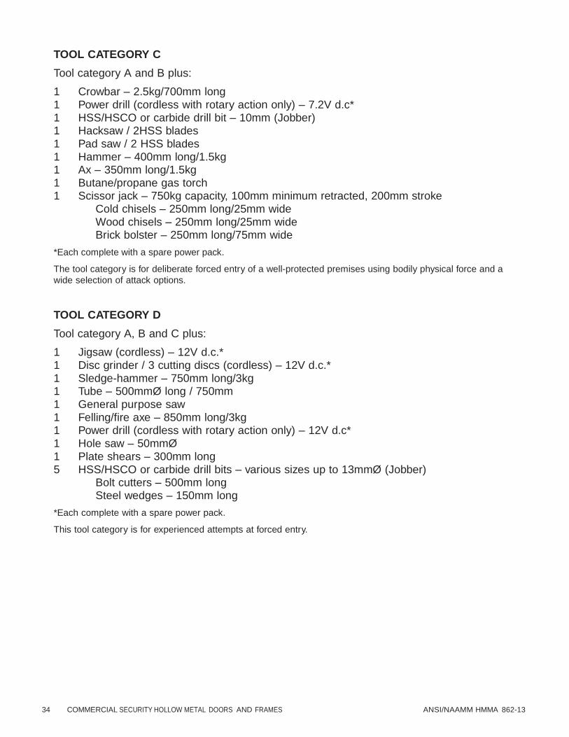
34 COMMERCIAL SECURITY HOLLOW METAL DOORS AND FRAMES ANSI/NAAMM HMMA 862-13
TOOL CATEGORY C
Tool category A and B plus:
1 Crowbar – 2.5kg/700mm long 1 Power drill (cordless with rotary action only) – 7.2V d.c* 1 HSS/HSCO or carbide drill bit – 10mm (Jobber) 1 Hacksaw / 2HSS blades 1 Pad saw / 2 HSS blades 1 Hammer – 400mm long/1.5kg 1 Ax – 350mm long/1.5kg 1 Butane/propane gas torch 1 Scissor jack – 750kg capacity, 100mm minimum retracted, 200mm stroke
Cold chisels – 250mm long/25mm wide Wood chisels – 250mm long/25mm wide Brick bolster – 250mm long/75mm wide
*Each complete with a spare power pack.
The tool category is for deliberate forced entry of a well-protected premises using bodily physical force and a
wide selection of attack options.
TOOL CATEGORY D
Tool category A, B and C plus:
1 Jigsaw (cordless) – 12V d.c.* 1 Disc grinder / 3 cutting discs (cordless) – 12V d.c.* 1 Sledge-hammer – 750mm long/3kg 1 Tube – 500mmØ long / 750mm 1 General purpose saw 1 Felling/fire axe – 850mm long/3kg 1 Power drill (cordless with rotary action only) – 12V d.c* 1 Hole saw – 50mmØ 1 Plate shears – 300mm long 5 HSS/HSCO or carbide drill bits – various sizes up to 13mmØ (Jobber)
Bolt cutters – 500mm long Steel wedges – 150mm long
*Each complete with a spare power pack.
This tool category is for experienced attempts at forced entry.

ANSI/NAAMM HMMA 862-13 COMMERCIAL SECURITY HOLLOW METAL DOORS AND FRAMES 35
TOOL CATEGORY E
Tool category A, B, C and D plus:
1 Circular saw – 200mmØ/1100W 1 Sledge-hammer – 750mm/6kg. 1 Reciprocating saw – 750W 1 Disc grinder / 3 cutting discs – 125mm/1100W 1 Power drill with rotary/hammer action – 750W 1 Pinch bar – 1500mm long 5 HSS/HSCO or carbide drill bits – various sizes up to 13mmØ (Jobber and long series)
Wood boring spade bits Hole saws>50mmØ
This tool category provides a professional means of attempting forced entry into hinge value storage areas
generally after penetrating the façade.
TOOL CATEGORY F
Tool category A, B, C, D and E plus:
1 Circular saw – 300mmØ/2100W 1 Reciprocating saw – 2000W 1 Disc grinder/3 cutting disc – 250mmØ/2300W 1 Power drill with rotary/hammer action – 2000W 1 Tube – 1500mm long/75mm 1 Saffire “Portapak” cutting blowtorch kit 5 HSS/HSCO or carbide drill bits – various sizes up to 20mm
This tool category is an enhancement of category E.
Note: All dimensions are maximum unless otherwise specified.

36 COMMERCIAL SECURITY HOLLOW METAL DOORS AND FRAMES ANSI/NAAMM HMMA 862-13
WELDS
FIGURE 8
FACE
+/- 1/32 IN. (0.8MM)
STOP
+/- 1/32 IN. (0.8MM)
RETURN
RABBET
+/- 1/32 IN. (0.8MM)
FRAME DEPTH
+/- 1/32 IN. (0.8MM)
THROAT OPENING
+/- 1/16 IN. (1.5MM)
SOFFIT
FIGURE 9

ANSI/NAAMM HMMA 862-13 COMMERCIAL SECURITY HOLLOW METAL DOORS AND FRAMES 37
The contractor responsible for installation shall remove
wraps or covers from doors and frames upon delivery
at the building site. The contractor responsible for
installation shall ensure that scratches or disfigurements
caused in shipping or handling are promptly cleaned and
touched up with a rust inhibitive primer.
WOOD PLANKING
WOOD PLANKING
The contractor responsible for installation shall
ensure that materials are properly stored on planks or
dunnage in a dry location. Doors shall be stored on
their heads in a vertical position, to protect sound
gasketing at the door bottom, and shall be spaced by
blocking. Materials shall be covered to protect them
from damage but in such a manner as to permit air
circulation.
WOOD PLANKING
FIGURE 10
Recommended Storage
WOOD PLANKING
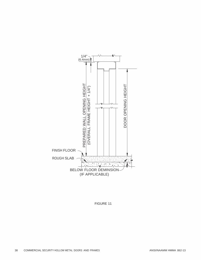
38 COMMERCIAL SECURITY HOLLOW METAL DOORS AND FRAMES ANSI/NAAMM HMMA 862-13
PR
EP
AR
ED
WA
LL O
PE
NIN
G H
EIG
HT
(OV
ER
AL
L F
RA
ME
HE
IGH
T +
1/4
")
DO
OR
OP
EN
ING
HE
IGH
T
1/4" (6.4mm)
FINISH FLOOR
ROUGH SLAB
BELOW FLOOR DEMINSION
(IF APPLICABLE)
FIGURE 11

ANSI/NAAMM HMMA 862-13 COMMERCIAL SECURITY HOLLOW METAL DOORS AND FRAMES 39
MAXIMUM TOLERANCE
1/16 IN. (1.5MM)
90°
SQUARENESS; MEASURED AT RABBET ON A LINE FROM JAMB PERPENDICULAR TO FRAME HEAD.
HEAD
MAXIMUM TOLERANCE 1/16 IN. (1.5MM)
HINGE OR STRIKE JAMB
PLUMBNESS; MEASURED AT JAMBS ON A PERPENDICULAR LINE FROM THE HEAD TO THE FLOOR.
PROFILE MAY VARY AS A FUNCTIONAL DESIGN
ALIGNMENT; MEASURED AT JAMBS ON A HORIZONTAL LINE PARALLEL TO THE PLANE OF THE FACE.
90°
TWIST; MEASURED AT OPPOSITE FACE CORNERS OF JAMBS ON PARALLEL LINES, PERPENDICULAR TO THE PLANE OF THE DOOR RABBET.
FIGURE 12
Installation Tolerances
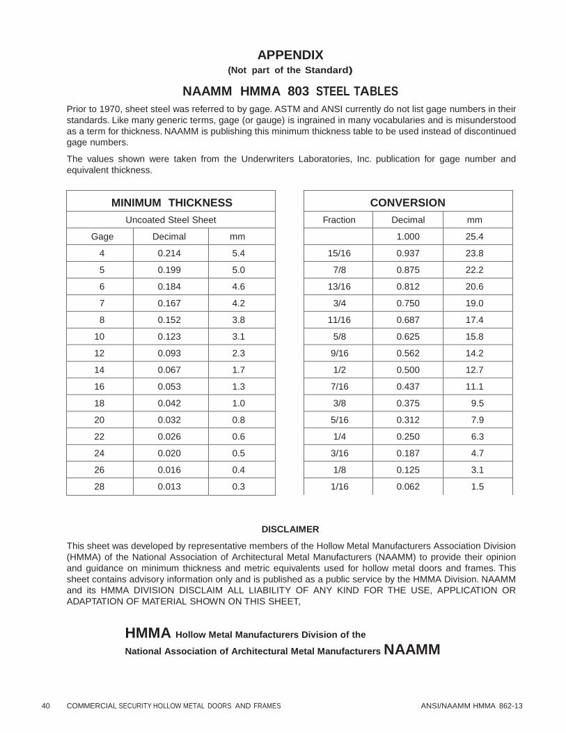
40 COMMERCIAL SECURITY HOLLOW METAL DOORS AND FRAMES ANSI/NAAMM HMMA 862-13
CONVERSION
Fraction Decimal mm
1.000 25.4
15/16 0.937 23.8
7/8 0.875 22.2
13/16 0.812 20.6
3/4 0.750 19.0
11/16 0.687 17.4
5/8 0.625 15.8
9/16 0.562 14.2
1/2 0.500 12.7
7/16 0.437 11.1
3/8 0.375 9.5
5/16 0.312 7.9
1/4 0.250 6.3
3/16 0.187 4.7
1/8 0.125 3.1
1/16 0.062 1.5
APPENDIX (Not part of the Standard)
NAAMM HMMA 803 STEEL TABLES
Prior to 1970, sheet steel was referred to by gage. ASTM and ANSI currently do not list gage numbers in their
standards. Like many generic terms, gage (or gauge) is ingrained in many vocabularies and is misunderstood
as a term for thickness. NAAMM is publishing this minimum thickness table to be used instead of discontinued
gage numbers.
The values shown were taken from the Underwriters Laboratories, Inc. publication for gage number and
equivalent thickness.
MINIMUM THICKNESS
Uncoated Steel Sheet
Gage Decimal mm
4 0.214 5.4
5 0.199 5.0
6 0.184 4.6
7 0.167 4.2
8 0.152 3.8
10 0.123 3.1
12 0.093 2.3
14 0.067 1.7
16 0.053 1.3
18 0.042 1.0
20 0.032 0.8
22 0.026 0.6
24 0.020 0.5
26 0.016 0.4
28 0.013 0.3
DISCLAIMER
This sheet was developed by representative members of the Hollow Metal Manufacturers Association Division
(HMMA) of the National Association of Architectural Metal Manufacturers (NAAMM) to provide their opinion
and guidance on minimum thickness and metric equivalents used for hollow metal doors and frames. This
sheet contains advisory information only and is published as a public service by the HMMA Division. NAAMM
and its HMMA DIVISION DISCLAIM ALL LIABILITY OF ANY KIND FOR THE USE, APPLICATION OR
ADAPTATION OF MATERIAL SHOWN ON THIS SHEET,
HMMA Hollow Metal Manufacturers Division of the
National Association of Architectural Metal Manufacturers NAAMM
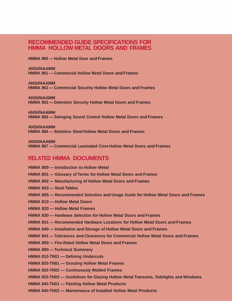
RECOMMENDED GUIDE SPECIFICATIONS FOR HMMA HOLLOW METAL DOORS AND FRAMES
HMMA 860 — Hollow Metal Door and Frames
ANSI/NAAMM HMMA 861 — Commercial Hollow Metal Doors and Frames
ANSI/NAAMM HMMA 862 — Commercial Security Hollow Metal Doors and Frames
ANSI/NAAMM HMMA 863 — Detention Security Hollow Metal Doors and Frames
ANSI/NAAMM HMMA 865 — Swinging Sound Control Hollow Metal Doors and Frames
ANSI/NAAMM HMMA 866 — Stainless Steel Hollow Metal Doors and Frames
ANSI/NAAMM HMMA 867 — Commercial Laminated Core Hollow Metal Doors and Frames
RELATED HMMA DOCUMENTS
HMMA 800 — Introduction to Hollow Metal
HMMA 801 — Glossary of Terms for Hollow Metal Doors and Frames
HMMA 802 — Manufacturing of Hollow Metal Doors and Frames
HMMA 803 — Steel Tables
HMMA 805 — Recommended Selection and Usage Guide for Hollow Metal Doors and Frames
HMMA 810 — Hollow Metal Doors
HMMA 820 — Hollow Metal Frames
HMMA 830 — Hardware Selection for Hollow Metal Doors and Frames
HMMA 831 — Recommended Hardware Locations for Hollow Metal Doors and Frames
HMMA 840 — Installation and Storage of Hollow Metal Doors and Frames
HMMA 841 — Tolerances and Clearances for Commercial Hollow Metal Doors and Frames
HMMA 850 — Fire-Rated Hollow Metal Doors and Frames
HMMA 890 — Technical Summary
HMMA 810-TN01 — Defining Undercuts
HMMA 820-TN01 — Grouting Hollow Metal Frames
HMMA 820-TN02 — Continuously Welded Frames
HMMA 820-TN03 — Guidelines for Glazing Hollow Metal Transoms, Sidelights and Windows
HMMA 840-TN01 — Painting Hollow Metal Products
HMMA 840-TN02 — Maintenance of Installed Hollow Metal Products