hochbau - fib-ch.epfl.ch · costruttivi per il calcestruzzo facciavista di classe cpn c è stata...
TRANSCRIPT


Hochbau
Bâtiment
Buildings

12
Periscopio di Pollegio: la struttura portante di una scultura di calcestruzzoThe Periscope of Pollegio: the prestressed structure of a concrete sculpture
Cristina Zanini Barzaghi
Introduzione Il Periscopio, così chiamato fin dalmotto che abbiamo adottato peril progetto di concorso, è la nuovatorre di controllo di Alptransit-FFSa Pollegio. L’edificio marca in mo -do inconfondibile il paesaggio inprossimità del portale sud dellagalleria di base del San Gottardoed è stato pensato per essere am -mirato in velocità. La sua formascultorea è sviluppata in verticalee si contrappone idealmente alfluire delle linee orizzontali di
Introduction The Periscope is the new controltower of Alptransit – the stretchof railway with a 50 km tunnelthrough the Alps – in Pollegio, socalled because of the key wordused in the project competition.Due to its architectural appear -ance, the building marks thelandscape around the south por-tal at Gotthard Base Tunnel. Itsdesign is intended to be fullyappreciated at high speed. Itssculptural shape highlights the
traffico presenti nel fondovalledella Leventina (Fig. 1).La forma di periscopio, con la«scatola» superiore con sbalziasimmetrici e il «fusto» inferioremassiccio, e la struttura portantein calcestruzzo armato precom-presso faccia a vista sono precisescelte fatte sin dall’inizio con gliarchitetti (Fig. 2). Lo studio di soluzioni creativenella fase iniziale del progetto èstato particolarmente stimolante.Per il calcolo statico, la struttura è
Fig. 1
Vista del Periscopio da sud-est.View of the building from south-east.(© Hélène Binet)

13
stata scomposta in elementi bidi-mensionali verticali e orizzontaliche riprendono sia carichi verticalisia orizzontali. I flussi delle forzesono stati modellati sia con i me -todi tradizionali basati sulla stati-ca grafica, come i tralicci e i campidi tensione, sia con il calcolo in for -matico con elementi finiti lineari,a due o tre dimensioni. Quest’ul -ti mi hanno richiesto molto impe-gno per la loro interpretazione,vista l’importante interazione frai diversi elementi strutturali. I di -mensionamenti sono stati svolticonsiderando differenti equilibriidi forze così da ottenere unastruttura efficiente con una certaridondanza, nel contempo econo-micamente sostenibile. Sono statiinoltre approfonditi molti aspettiparticolari, quali la ripartizionefra flessione antimetrica e torsio-ne nella copertura, la progetta-zione delle centinature (Fig. 3), laprecompressione in tre direzioni,la distribuzione delle forze suipali e l’interazione fra terreno e
vertical, forming a perfect con-trast with the flow of the hori-zontal traffic lines of the Le ven -tina valley floor (Fig. 1). Specific design choices weremade by the architects, such asthe ”periscope” shape (with the”box” with asymmetrical cantile-vers on the massive ”shaft”) andthe structure made of reinforced,prestressed and fair-faced con -crete (Fig. 2). Coming up with solutions for thedesign of the complex structurewas a very creative challenge. Inan initial approach, the structurewas divided into walls and slabs(two-dimensional elements) andthe vertical and horizontal loadswere analysed separately. Theflows of the forces were modelledboth with traditional methods,based on graphic statics (such asstrut-and-tie and stress fields) andwith finite element modelling.The interpretation of outputsfrom the finite element methodrequired an intensive analysis and
ultimately allowed the importantinteraction between the multiplestructural elements to be con -firmed. The design of the structu-ral elements was carried out withsev er al variations of the forceflow, in order to obtain an effi-cient structure that is balanced atall times, with some structuralredundancy. Of course, at thesame time, the criteria of econo-mics and sustainability were con-sidered and carefully integratedinto the considerations. Manyspecific aspects were analysed indetail, such as the distributionratio in the roof element bet-ween anti-metric bending andtorsion, the design requirementsfor the scaffolding under the can-tilevers (Fig. 3), the three-dimen-sional prestressing, the distributi-on of the forces between thevarious foundation piles, and theinteraction between foundationand building.
Concrete technology andconstructional aspectsAn already tested recipe, alreadylargely adopted on the Alptransitsites, that uses high quality alluvi-al aggregates from Hüntwangen,has been employed for the fair-faced concrete (as well as CPN C). The external walls have beenthermally insulated internally.Great attention has also beenpaid to the design of the form-work. Minute details such as sharpedges and treatment against rustfrom reinforcing bars were alsotaken care of. The arrangementof the anchorage points for thepost-tensioning tendons was alsodesigned in accordance with thearchitectural requirements. The minimum ratio of reinforce-ment was determined accordingto the standard SIA 262 in orderto limit large cracks and deforma-tions to an admissible level. Fromthe monitoring carried out afterfinishing the construction, verysmall cracks within the limits ofdefined deformations in the SwissCodes (less than 0.2 mm) wereobserved. Also deformation wastraced at several monitoring pointsthroughout the building, at vari -ous times during and after erection
Fig. 2
Particolare del calcestruzzo facciavista sul fronte ovest.Detail of exposed concrete on the western facade.(© Hélène Binet)

14
edificio. È difficile ri assumere illavoro svolto in poche righe:segue perciò la descrizione succin-ta della struttura.
Materiali e accorgimenticostruttiviPer il calcestruzzo facciavista diclasse CPN C è stata adottata unaricetta già ampiamente testatanei cantieri di Alptransit, con iner-ti alluvionali di alta qualità daHüntwangen. Le pareti portantiesterne sono state isolate termi-camente all’interno, prevedendo inecessari risvolti per contenere iponti di freddo. È stata dedicatagrande attenzione al disegno deicasseri e dei distanziatori. Sonostati curati anche dettagli minuti
of the concrete structure. Dis -place ments of a few millimetreswere observed both vertically andhorizontally. The different moni-toring systems adopted enablethe plausibility of the numericalmodel to be verified. The datacollected confirms that the actualstructural behaviour is stronglyinfluenced by the torsion of thewhole structure.The concept of the entire structur -al system took full account of therequirements of the technicalequipment. Lowered ceilings andtechnical floors, as well as verticaltechnical compartments, havebeen provided to allow maximumflexibility for the technical equip-ment and to avoid the placement
quali gli spigoli vivi acuti e il trat-tamento contro la ruggine deiferri di ripresa: anche la disposi-zione delle nicchie di tesatura deicavi è stata concordata con gliarchitetti.L’armatura minima è stata defini-ta in base alle esigenze accresciu-te per la fessurazione secondo lanorma SIA 262. Dai rilievi eseguitidopo il cantiere abbiamo consta-tato fessure molto contenute conaperture entro i limiti della norma(inferiori a 0,2 mm). Pure le defor-mazioni nei punti caratteristicidell’edificio sono state misuratein più momenti durante e dopo ilcantiere. Si sono manifestati spo-stamenti di pochi millimetri sia inverticale sia in orizzontale. I diver-si monitoraggi permettono di ve -ri ficare la plausibilità del calcolostatico e di constatare che il com-portamento reale è fortementeinfluenzato dalla resistenza tor-sionale della struttura.La predisposizione di soffitti ri -bassati e pavimenti tecnici, comepure la presenza di vani tecniciverticali permette la massima fles-sibilità per le infrastrutture. L’in -tero sistema strutturale è statoconcepito senza inserti e con unarigorosa pianificazione delle foro-metrie richieste dall’impiantistica.
Scatola superiore con traviparete precompresseLa «scatola» superiore della strut-tura in calcestruzzo armato è pre-compressa con 60 cavi rettilinei inpost-tensione con aderenza, dispo -sti nelle tre direzioni e tesati dopol’ultimazione dell’intera strut tura
Dati principali/Main figuresm3 SIA 26 000 m3
Calcestruzzo tipo C/Concrete type C 6 000 m3
Armatura B500B/Reinforcement B500B 900 tAcciaio/Steel S355 26 tPrecompressione/ 60 caviPretensioning totale 1650 mPali di fondazione/ 35 pzFoundation piles totale 750 m
Costi complessivi/Overall costs CHF 30 mio.
Struttura grezza/Structural works 2010–2012Inaugurazione/Opening 2014
Fig. 3
Piattaforme per esecuzione delle parti aggettanti.Scaffolding for the cantilevered parts.(© ORCH – Alessandra Chemollo)

15
of electrical cables and tubingwithin the concrete structure.
Cantilevered box andshear wallsThe upper part of the reinforcedconcrete structure (“cantileveredbox”) is prestressed with 60straight post-tensioned cableswith adherence (Fig. 4). They arearranged in three directions andwere tensioned after completingthe roof-slab. The pretensioningis carried out with an electric con-trol system (type C), adopted asstandard in bridge constructionbut quite unusual in buildings. The roof on the control room inthe “cantilevered box” is designedas a box girder bridge with fourpretensioned longitudinal beamswith a span of about 33 metresand a variable height from 1.80to 3.30 metres (Fig. 5).The roof slab has a thicknessrang ing from 25 to 35 cm and isshaped like a butterfly with alower fold on the diagonal of theroof, used for the discharge ofrainwater. The large volume ofthe “box” houses office rooms onthe upper level, which are sus -pended from the roof with steelbars in order to leave the lowerspace completely free from anysupport and transparent fromfacade to facade. The loads actingon the cantilevered box are trans-fered to the lower ”shaft” bymeans of four shear walls pre-stressed with vertical and hori-zontal cables. The position of theopenings in these shear walls wasstudied very carefully, especiallyfor the south facade, with a canti-lever of 17 metres (Fig. 6). Theeast and west facades with largewindows help to resist the torsionresulting from the two asymme-
grezza (Fig. 4). La precompressio-ne è stata predisposta con un con-trollo elettrico (tipo C) equipara-bile a quello impiegato nei ponti,ma non usuale nell’edilizia. La copertura della sala comando èsimile a quella dei ponti a cassone,con quattro travi longitudinali pre -compresse di luce di ca. 33 m e dialtezza variabile da 1,80 a 3,30 m.La soletta ha uno spessore varia-bile da 25 a 35 cm, ed è conforma-ta a due falde con un compluviosulla diagonale per il deflussodelle acque piovane. Gli uffici delsesto piano, inseriti nel grandevolume della scatola superiore,sono sospesi alla copertura contiranti d’acciaio, così da lasciare lasala comando libera da ogniappoggio e trasparente da faccia-ta a facciata. (Fig. 5)I carichi aggettanti della scatolasuperiore sono ripresi principal-mente da quattro travi paretitrasversali rispetto al fusto e rin-forzate con cavi di precompressio-ne verticali e orizzontali. La dispo-
trical cantilevered parts of thebuilding.
Massive “shaft” and foundationsThe lower part of the building,shaped like a solid shaft, housesthe technical equipment, which ischaracterised by heavy loads. Theflat slabs (35 cm) are supported bysome internal columns up to thefourth floor. Massive perimeterwalls, which uniformly distributethe forces to the founda tions, aredesigned and construct ed towithstand the mainly verticalload. Bespoke flag-shaped steelplates, provided with shear con-nectors (Fig. 7), are inserted in thewalls at the interfaces with thecantilever boxes. They facilitatethe transfer of the large concen-trated forces from the boxes intothe facade walls of the centralbuilding core. The building is founded on asandy-gravelly alluvial soil ofgood quality but not very consoli-
Committente/OwnerFerrovie federali svizzere FFS SA,Lucerna; Alptransit Gottardo SA,BellinzonaArchitettura/ArchitectBruno Fioretti Marquez architettiSagl, Lugano-BerlinoIngegnere civile/Civil engineerBorlini & Zanini SA, MontagnolaImpresa costruzioni/ContractorCSC Impresa costruzioni SA, Lugano
Fig. 4
Schema della precompressione della scatola superiore.Prestressing system for upper “cantilevered box”.

16
sizione delle aperture in questetravi è stata studiata attentamen-te, in particolare per la facciatasud che risulta a sbalzo per 17 m(Fig. 6). Le facciate con grandi ve -trate a est e ovest contribuisconoad equilibrare la torsione risultan-te dai due aggetti asimmetrici.
Fusto inferiore e fondazioniLa parte inferiore dell’edificio èconformata come «fusto» massic-cio e racchiude gli spazi riservatialla tecnica, dove sono previsticarichi utili elevati. Le solettepiane di 35 cm prevedono fino alquarto piano delle colonne inter-medie. La discesa dei carichi verti-cali avviene prevalentementenelle pareti perimetrali del fusto,le quali essendo molto massicce,ripartiscono uniformemente leforze sulle fondazioni. In corri-spondenza delle travi parete tras-versali dei piani superiori sonoinseriti degli appositi profilati abandiera in acciaio con connetto-ri, per garantire il passaggio dellegrandi forze concentrate dalla sca -tola superiore al fusto (Fig. 7).L’edificio è appoggiato su terrenoalluvionale ghiaioso-sabbioso dibuona qualità ma poco addensa-to. Nel sottosuolo è presenteacqua di falda già a partire daqualche metro sotto la superficie,perciò l’edificio è stato eseguitosenza piani interrati, con un solovano tecnico realizzato con calce-struzzo impermeabile.
dated. Groundwater is alreadypresent at a few metres belowthe surface, which is why the build -ing was built without a basementand with only one technical com-partment, made of waterproofconcrete. The foundation systemwith bored piles of 1.2 metres indiameter, and with a length ofabout 22 metres, was preferredfor several reasons: the very low,almost imperceptible differentialsettlements, which is significantfor the cantilevered parts; thelower costs, if compared to a sur-face foundation; the limitedspace requirement, given that theconstruction site had to be ar -ranged in a very small area. The loads of the two asymmetri-cal cantilevers counterbalanceeach other. The resultant verticaldesign force at the foundationlevel, approximately 37,000 kN,acts at precisely the centroid ofthe building shaft footprint.
Seismic stabilityIn term of seismic design, thebuilding is considered to be with -in category II and with reducedductility. The seismic analyses ofthe structure were performedusing the static equivalent meth -od with horizontal forces of about9% of vertical loads. Despite theparticular shape of the building,the downward continuity of theprincipal walls allows a directforce flow to the foundations. A
Il sistema di fondazione con palitrivellati di diametro di 1,2 m elunghezza di ca. 22 m è stato pre-ferito per più motivi: non solo pergli assestamenti differenziali moltocontenuti e impercettibili anchenelle parti aggettanti, ma ancheper i costi più favorevoli rispettoalle fondazioni superficiali, e perla contenuta necessità di spazio;esigenza tutt’altro che trascurabi-le in un cantiere che ha dovutoessere organizzato in un’area ri -dottissima.Globalmente i carichi dei dueaggetti asimmetrici si controbi-lanciano e la risultante delle forzeverticali complessive a livello difondazione, pari a ca. 37 000 kN adimensionamento, è posizionatasorprendentemente nel baricen-tro del fusto.
Stabilità sismicaPer la sismica l’edificio è conside-rato con classe d’opera II e conduttilità ridotta: per il dimensio-namento sono considerate forzesostitutive sismiche, pari a ca. il9% dei carichi verticali. Nono stan -te la conformazione particolaredell’edificio, la continuità verso ilbasso dei corpi verticali ubicatialle due estremità dell’edificioper mette un’ottimale ripresa edistribuzione delle sollecitazioninel terreno. Un approfondimentospecifico è stato eseguito per ga -rantire la trasmissione delle forzeorizzontali nel terreno attraverso
Fig. 5
Assonometria, pianta e sezione del sistema portante.Axonometry, horizontal and vertical sections of the structural system.

17
specific study was carried out toguarantee the transmission ofhorizontal forces into the groundby the bending of the upper partof the founda tion piles.
Conclusions “Structural engineering is the artof forming shapes that cannot beanalysed in reality, with unknownmaterials, to face forces that can-not be evaluated, in such a waythat all traces are invisible.” ThePeriscope is well suited to this ironic definition by St. Kelsey,because of its complex structuralconcept. This project represents animportant moment of professio-nal growth for our firm, especiallyregarding the interdisciplinarywork involved.
la flessione della parte superioredei pali di fondazione.
Conclusioni e ringrazia-menti«L’ingegneria strutturale è l’artedi formare con materiali che nellarealtà non si conoscono, delleforme che nella realtà non si pos-sono analizzare, per resistere adelle forze che nella realtà non sipossono valutare, in modo taleche la gente non possa, nella real-tà, sospettarlo.» Questa ironica definizione di S.Kelsey ben si adatta al Periscopio,visto che non è semplice spiegareil suo concetto strutturale. Per ilnostro studio si è trattato di unmomento di crescita professiona-le importante, in particolare per illavoro interdisciplinare svolto nelteam di progetto. Ringraziamo inparticolare la committenza, lostudio d’architettura e l’impresacostruzioni per la collaborazioneproficua.
Fig. 6
Schema della trave parete a sbalzocon carichi e campi di tensione.Cantilevered shear wall with loadsand stress fields.
Fig. 7
Elemento metallico a bandiera per introduzione delle forzeconcentrate.Steel flag-profile for introduction of concentrated forces.
Autrice/Author
Cristina Zanini BarzaghiIng. civile dipl. ETHZ SIA OTIABorlini & Zanini SACH-6926 [email protected]
18
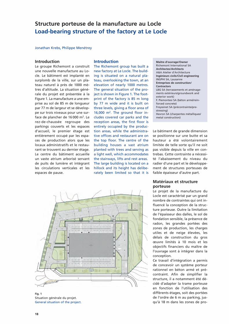
IntroductionLe groupe Richemont a construitune nouvelle manufacture au Lo -cle. Le bâtiment est implanté ensurplomb de la ville, sur un pla-teau naturel à près de 1000 mè -tres d’altitude. La situation géné-rale du projet est présentée à laFigure 1. La manufacture a une em -prise au sol de 85 m de lon gueurpar 77 m de largeur et se dévelop-pe sur trois niveaux pour une sur-face de plancher de 16 000 m2. Lerez-de-chaussée regroupe desparkings couverts et les espacesd’accueil, le premier étage estentièrement occupé par les espa-ces de production alors que leslocaux administratifs et le restau-rant se trouvent au dernier étage.Le centre du bâtiment accueilleun vaste atrium arborisé servantde puits de lumière et intégrantles circulations verticales et lesespaces de pause.
IntroductionThe Richemont group has built anew factory at Le Locle. The build -ing is situated on a natural pla-teau, overlooking the town, at anelevation of nearly 1000 metres.The general situation of the pro-ject is shown in Figure 1. The foot -print of the factory is 85 m longby 77 m wide and it is built onthree levels, giving a floor area of16,000 m2. The ground floor in -cludes covered car parks and thereception areas, the first floor isen tirely occupied by the produc -tion areas, while the administra -tive offices and restaurant are onthe top floor. The centre of thebuilding houses a vast atriumplanted with trees and serving asa light well, which accommodatesthe stairways, lifts and rest areas.The large building is located on ahillock and its height has delibe-rately been limited so that it is
Le bâtiment de grande dimensionse positionne sur une butte et sahauteur a été volontairementlimitée de telle sorte qu’il ne soitpas visible depuis la ville en con-trebas. Cette contrainte a nécessi-té l’abaissement du niveau duradier d’une part et le développe-ment de structures porteuses defaible épaisseur d’autre part.
Matériaux et structure porteuseLe projet de la manufacture duLocle est caractérisé par un grandnombre de contraintes qui ont in -fluencé la conception de la struc -ture porteuse. Outre la limita tionde l’épaisseur des dalles, le sol defondation sensible, la présence deradon, les grandes portées deszones de production, les chargesutiles et de neige élevées, lesdélais de construction du grosœuvre limités à 10 mois et lesobjectifs financiers du maître del’ouvrage sont à intégrer dans laconception.Ce travail d’intégration a permisde concevoir un système porteurrationnel en béton armé et pré-contraint. Afin de simplifier lastructure, il a notamment été dé -cidé d’adapter la trame porteuseen fonction de l’utilisation desdifférents étages, soit des portéesde l’ordre de 6 m au parking, jus-qu’à 18 m dans les zones de pro-
Jonathan Krebs, Philippe Menétrey
Structure porteuse de la manufacture au LocleLoad-bearing structure of the factory at Le Locle
Fig. 1
Situation générale du projet.General situation of the project.
Maitre d’ouvrage/OwnerRichemont International SAArchitectes/ArchitectsA&A Atelier d’Architecture Ingénieurs civils/Civil engineeringINGPHI SA, LausanneEntreprises de construction/ContractorsLBG SA (terrassements et aménage-ments extérieurs/groundwork andexterior work)F. Piemontesi SA (béton armé/rein -forced concrete)Freyssinet SA (précontrainte/pre -stressing)Hevron SA (charpentes métalliques/metal construction)

19
not visible from the town below.This constraint required, on theone hand, that the level of theraft was lowered and, on theother hand, the development ofthin load-bearing structures.
Materials and load-bearingstructureThe Le Locle factory project is cha-racterised by a large number ofconstraints that have influencedthe design of the load-bearingstructure. Apart from the limita -tion of the thickness of the slabs,the soft ground on which it isfounded, the presence of radon,the large spans of the productionareas, the high snow loading, thedeadlines for completion of thestructural work limited to 10months and the fi nancial targetsof the client company had to beincluded in the design.Taking all this into account led tothe design of a rational load-bear ing system in reinforced andprestressed concrete. In order tosimplify the structure, it was de -cid ed, in particular, to adapt theload-bearing framework accord -ing to the use of the differentfloors, namely, spans of the orderof 6 m in the parking area, up to18 m in the production areas andup to 11 m on the top floor. Theslab over the parking area andthe roof slab were thus simplifiedand the major challenge of theproject was concentrated in theslab over the production areas.The cross-section shown in Figure2 illustrates the structural princi-ples developed.
RaftThe building is founded on a ge -neral raft reinforced by a grid ofstringers resting on the molasse
duction et jusqu’à 11 m au der-nier étage. Ainsi les dalles sur par-king et de toiture ont été simpli-fiées et l’enjeu majeur du projets’est concentré sur la dalle au-des-sus des locaux de production. La coupe transversale présentée àla Figure 2 illustre les principesstruc turels développés.
RadierLe bâtiment est fondé sur un ra diergénéral renforcé par une grille delongrines appuyées sur la molassede la vallée du Locle dont la por-tance est bonne.Au-dessus des locaux habités, le ra -dier fait office de barrière au ra -don. Il est réalisé sans joints de di -latation, son épaisseur est de 25 cmet ses armatures sont dimension-nées de manière à respecter lesexigences accrues de fissurationafin que le béton puisse être con-sidéré étanche.Pour des questions de durabilité,le radier s’étend sous les parkingscouverts limitant ainsi les risquesliés aux tassements différentiels.
Dalle de productionLa dalle supportant l’étage deproduction reprend une chargeutile de 1000 kg/m2 nécessaire àl’exploitation de la manufacture.Afin d’en limiter la hauteur stati-que et d’en simplifier la construc-tion, il a été décidé de réduire lesportées à un maximum de 6,30 met donc d’augmenter le nombrede piliers au parking. Ces mesuresont permis de limiter l’épaisseurde la dalle à 35 cm.
Dalle sur productionLa dalle sur l’étage de productionest caractérisée par des grandespor tées et des charges importan-tes de neige.
of the Le Locle valley, which hasgood load-bearing capacity.The raft forms a radon barrier be -neath the inhabited parts of thebuilding above. It was producedwithout expansion joints, is 25 cmthick and its reinforcement issized to meet the increased requi-rements with regard to crackingso that it can be considered leak-proof.For reasons of durability, extendsbeneath the covered parking areas,
thus limiting the risks aris ing fromdifferential settlement.
Production floor slabThe slab supporting the produc -tion floor supports a working loadof 1000 kg/m2, required for thema nufacturing operations. Inorder to limit its static height andsimplify its construction, it wasdecided to reduce the spans to amaximum of 6.30 m and there -fore increase the number of pil-lars in the parking areas. Thesemeasures enabled the thicknessof the slab to be limited to 35 cm.
Slab over productionThe slab over the production flooris characterised by large spans andhigh snow loading.
Roof slabThe roof slab covers spans varyingfrom 5.40 m to 10.80 m. The largespans occur in the administrativeoffices, where the columns areintegral with the partitions, andin the restaurant, which is free ofany pillars. It was decided to re -tain a constant thickness of 35 cmand to manage the deformationsin critical areas by means of pre-cambering.To the south, the restaurant is pro -longed by a large terrace, cover ed
±0,00
+4,20
+9,95 Administratif | Restaurant
Locaux de production
Parking | Techniques
+14,25 Toiture
Fig. 2
Coupe transversale.Cross-section.

20
Dalle toitureLa dalle toiture franchit des por-tées variant de 5,40 m à 10,80 m.Les grandes portées se trouventdans les locaux administratifs oùles colonnes sont intégrées auxcloisons et dans le restaurant quiest libre de tout pilier. Il a étédécidé de conserver une épaisseurconstante de 35 cm et de gérer lesdéformations des zones critiquespar la mise en œuvre de contre-flèches.Au sud, le restaurant est prolongépar une grande terrasse couvertepar une casquette en béton. Cettedernière est réalisée par la pro-longation de la toiture qui est ap -puyée sur trois colonnes espacéesde plus de 14 m. La rupture ther-mique est réalisée par des conso-les isolantes de forte capacitédéveloppées pour le projet.
Structures de l’atriumL’atrium central est le cœur du bâ -timent. Il est marqué par un esca-lier monumental et des passerel-les d’accès aux différents espacesde travail, par une grande verriè-re en toiture et des plantationsmajeures. L’escalier est composéde deux murs dans lesquels s’en-castrent les volées d’escalier enporte-à-faux. La structure est en -tièrement monolithique, de tellesorte que les escaliers assurent le
by a concrete cap. The latter isprovided by a prolonga tion of theroof that rests on three columnsspaced by over 14 m. The thermalbreak is realised by means ofhigh-capacity insulating consolesdeveloped for the project.
Structures of the atriumThe central atrium is the heart ofthe building. It is marked by amonumental stairway and foot-bridges giving access to differentwork areas, by a large skylightroof and by major plantings. Thestairway is composed of two wallson which the stair flights are can-tilevered. The structure is entirelymonolithic, such that the stairsprovide bracing of the two walls.The two footbridges on the upperlevels were realised with ortho-tropic steel slabs in order to limittheir thickness to 16 cm for a totallength of 14.40 m. The centralstairway and the footbridges areillustrated in Figures 3 and 4.
contreventement des deux murs.Les deux passerelles aux étagesont été réalisées avec des dallesorthotropes en acier afin de limi-ter leur épaisseur à 16 cm pourune longueur totale de 14,40 m.L’escalier central et les passerellessont illustrés aux Figures 3 et 4.La verrière est quant à elle com-posée de neuf cadres métalliquesà sous-tension. Ces structures ontété développées de manière àfranchir les 14,40 m du vide cen-tral tout en maximisant l’apportde lumière naturelle.
Dalle cassette précontrainteLa dalle sur l’étage de productionest conçue pour porter bidirec tion -nellement sur des colonnes et desmurs espacés de 12,60 m à 18 m,libérant ainsi des surfaces de plusde 200 m2 de tout porteurs. Lastruc ture a également été in -fluen cée par deux contraintesd’exploitation spécifiques au pro-jet qui sont la création au plafond
Le projet en chiffresTerrassements 40 000 m3
Béton armé 11 000 m3
Acier d’armatures 1500 tPrécontrainte 23 500 mVolume construit 69 000 m3
Coût des structures porteuses CHF 11 millions
The project in figuresGroundwork 40,000 m3
Reinforced concrete 11,000 m3
Reinforcing steel 1,500 tPrestressing cables 23,500 mBuilt volume 69,000 m3
Cost of structures 11 millions CHF
Fig. 3
Vue 3D de l’escalier central etdes passerelles.3-D view of the central stairwayand the foot bridges.
Fig. 4
Vue de l’atrium à la fin du gros œuvre.View of the atrium on completion of the structural work.

21
As for the skylight, this consists ofnine tensioned metal frames.These structures were developedto span the 14.40-m central voidwhile maximising the amount ofnatural light.
Prestressed cassette slabThe slab over the productionfloor is designed to bear in twodirections on columns and wallsspaced by 12.60 m to 18 m, thusfreeing areas of more than 200 m2
of any load-bearing support. Thestructure was also influenced bytwo operational constraints speci-fic to the project, which are thecreation beneath the ceiling of aservice plenum 60 cm high andfree of any structure and theneed to easily cut openings in theevent of a change in the fittingout of the production spaces. Thefact is that these constraintsexclude solutions of slabs withgirders or thick, flat slabs, even iflightened.A cassette slab was developed inorder to bridge the wide spanswhile limiting the static height. Inaddition, this solution, which con-sists in creating cavities in the un -derside of the slab, permits a struc -ture without girders and createsareas of small thickness favoura-ble to the creation of open ings.The slab has a thickness of 75 cm
d’un plénum technique de 60 cmde haut libre de toute struc ture etla nécessité de pouvoir aisémentréaliser des percements en casd’évolution de l’aménagementdes halles. En effet, ces contrain-tes excluent des solutions de dal-les avec sommiers ou de dallesplates épaisses, même allégées.Une dalle cassette a été dévelop-pée afin de franchir les grandesportées en limitant la hauteur sta-tique. Cette solution, qui consiste àcréer des évidements en sous-facede dalle, permet de plus de s’af-franchir de sommiers et de créerdes zones de faible épaisseur pro-pices à la création de percements.La dalle a une épaisseur de 75 cmet les évidements de 70 cm x 70 cmx 53 cm sont espacés de 90 cm,créant une grille de nervures or -thogonales. Le coffrage de ladalle est illustré à la Figure 5.Chaque nervure de 20 cm delarge est précontrainte en faceinférieure et supérieure. La pré-contrainte inférieure est compo-sée d’un monotoron T15s denuance d’acier Y1860S7-15.7 sui-vant un tracé rectiligne. La pré-contrainte supérieure, elle aussirectiligne, varie en fonction descontraintes et est réalisée avecdes monotorons et des câbles dedeux torons T15s et quatre toronsT15s tous de nuance d’acier
and the cavities are 70 cm x 70 cmx 53 cm, spaced by 90 cm, creatingan orthogonal grid of ribs. Theformwork for the slab is illustrat edin Figure 5.Each rib is 20 cm wide and pre-stressed on the upper and lowerfaces. The prestressing on thelower face consists of a single T15sstrand of steel grade Y1860S7-15.7 along a straight line. Theupper layer of prestressing, alsoin a straight line, varies accordingto the constraints and is imple-mented with single strands andcables of two T15s strands and fourT15s strands, all of steel gradeY1860S7-15.7. The prestressingcables are shown in plan in Figure6.The 6500 m2 were completed innine stages of about 400 m3 each,without working joints, and thewhole of the prestressing was carried out with factory assembledcables, coupled to the concretingjoints. The incorporation of thelarge number of cables in the slaband the relatively fine ribs re -quired an in-depth study of thecoupl ing and anchoring details ofthe prestressing, as illustrated inFigure 7. In order to keep themstraight and as low as possible,the bottom-face single strandswere coupled beyond the concret -ing joints to avoid any conflict
Fig. 5
Coffrage de la dalle cassette.Formwork for the cassette slab.

22
Y1860S7-15.7. Les câbles de pré-contrainte sont illustrés en plan àla Figure 6.La dalle de 6500 m2 est réalisée enneuf étapes d’environ 400 m3 cha-cune sans joints de travail et l’en-semble de la précontrainte a étéréalisée avec des câbles montésen usine et couplés aux joints debétonnage. L’intégration de l’im-portante quantité de câbles dansla dalle et les nervures relative-ment fines a nécessité une étudeapprofondie des détails de cou-plage et d’ancrage de la précon-
with the perpendicular prestress -ing.The high concentration of pre-stressing not only ensuresstrength in mid-span and at thepoint of support but also reducesthe minimum cracking reinforce-ment. In addition, the prestressingmade it possible to limit the dia-meters of the reinforcementinstalled and to reduce the pro-portion of reinforcement of theslab to 125 kg/m3.With its bi-directional behaviouradapted to the arrangement of
trainte, comme illustré à la Figure7. Afin de garder un tracé sansdéviations et le plus bas possible,les mono-torons inférieurs ontété couplés au-delàs des reprisesde bétonnage pour éviter toutconflit avec la précontrainte per-pendiculaire.La forte concentration de précon-trainte dans la dalle permet nonseulement d’assurer la résistanceà mi-travée et sur appui mais éga-lement de diminuer l’armature mi -nimale de fissuration. De plus, laprécontrainte a permis de limiterles diamètres des armatures misesen place et de réduire le taux d’ar - mature de la dalle à 125 kg/m3.La dalle cassette, par son compor-tement bidirectionnel adapté à ladisposition des porteurs de lahalle et grâce au recours à la pré-contrainte, a permis de franchirles portées conséquentes en gar-dant une hauteur statique raison-nable. De plus, les évidements ontpermis une importante économiede matériaux puisque le volumetotal de béton correspond à celuid’une dalle pleine de 45 cm. Pourfinir, une analyse comparative apermis de montrer que cette dallea un comportement équivalent àune dalle plate de 55 cm. La dallecassette représente donc une so -lution technique performante etéconomique pour le franchisse-ment de grandes portées.
ConclusionLa construction de la manufactureau Locle représentait un impor-tant défi, compte tenu de lanécessité de construire un bâti-ment rationnel et économiquedans un délai de 10 mois tout enintégrant un projet architecturalambitieux, et des contraintes par-ticulièrement exigeantes.La structure porteuse a ainsi étéoptimisée et une dalle cassette aété développée pour franchir lesgrandes portées, allant jusqu’à 18 m. Cette dalle cassette précon-trainte a un réel intérêt techniqueet économique. De plus, son as pectest particulièrement intéressantpour des structures apparentes.Le travail en étroite collaborationentre le maître de l’ouvrage, lesarchitectes et les ingénieurs a per-
12,60
12,603,60
18,00
3,60
12,60
12,60
12,60 14,40 14,40 14,40 14,40 12,60
77,46
84,66
Fig. 6
Vue en plan des câbles de précontrainte de la dalle cassette.Plan view of the prestressing cables of the cassette slab.
Fig. 7
Tracé et détails de la précontrainte dans les nervures.Line and details of the prestressing in the ribs.

23
the load-bearing supports of theproduction area and thanks to theuse of prestressing, the cassetteslab was able to bridge considera-ble spans while keeping its staticheight within reasonable bounds.Furthermore, the cavities per -mitted major savings of materials,since the total volume of concretecorresponds to that for a plainslab of 45 cm. Finally, a compara-tive analysis showed that this slabhas a behaviour equivalent to aflat slab of 55 cm. The cassette slabthus represents a solution forbridging wide spans with hightechnical and economic perfor-mance.
ConclusionThe construction of the Le Loclefactory presented a major chal-lenge, given the need to con-struct a rational and economicbuilding within 10 months, com-bining an ambitious architecturalproject and particularly demand -ing constraints.The load-bearing structure wasthus optimised and a cassette slabwas developed to bridge widespans of up to 18 m. This prestress -ed cassette slab is of real technicaland economic interest. Further -more, its appearance is particular-ly interesting for exposed struc -tures.The work, with close collaborationbetween the client, the architectsand the engineers, led to a facto-ry presenting a noble and elegantimage that fits in with the undu-lating topography of Le Locle.The load-bearing structure setsfree wide spaces, free of anycolumns, which illustrates the po -tential of structures in reinforcedand prestressed concrete.
mis la réalisation d’une manufac-ture à l’image noble et élégantequi suit la topographie vallonnéedu Locle. La structure porteuse apermis de libérer de grands espa-ces vierges de toutes colonnes, cequi illustre le potentiel des struc-tures en béton armé et précon-traint.
Fig. 8
Vue de la dalle cassette après décoffrage.View of the cassette slab after removal of formwork.
Fig. 9
Vue de la manufacture.View of the factory.
Auteurs/Authors
Jonathan Krebsing. civil [email protected]
Philippe MenétreyDr ès techn. ing. dipl. [email protected]
INGPHI SAConcepteurs d’ouvrages d’artCH-1003 Lausanne

24
Introduzione Per la nuova sede della dittaNamics si è costruito un nuovoedificio in una parcella libera nelmezzo del quartiere del ricamo diSan Gallo protetto dai monumen-ti storici. Molti degli edifici esi-stenti, costruiti attorno al 1910per ospitare gli atelier della fio-rente industria del ricamo, sonostati concepiti da Robert Maillartcon una struttura a scheletro incalcestruzzo armato celata da fac-ciate in muratura. Questo princi-pio è stato ripreso anche per ilnuovo edificio d’uffici, dove unastruttura in calcestruzzo armatoprecompresso, caratterizzata dadei solai a struttura pieghettata, èstata rivestita da facciate in mura-tura di laterizio. L’edificio è com-posto da 7 livelli (2 seminterrati e5 fuori terra): il livello più bassoaccoglie i locali tecnici e delle saledi riunione; i 5 livelli centrali sonodegli open-space e all’ultimo li -vello si trova un ristorante condue ampie terrazze. Tutti questispazi sono situati fra due nucleiposti agli estremi che accolgonole circolazioni verticali e alcuni lo -
IntroductionFor the new Namics firm head-quarters, a new building was builtin a free parcel in the middle ofthe embroidery quarter of St.Gal -len, surrounded by historicalmonuments. Many of the existingbuildings, built around 1910 tohost the ateliers of the boomingembroidery industry, were de -signed by Robert Maillart withreinforced concrete frames enve-lopped by brick façades. This prin-ciple was also used for the newoffice building, where a pre - stressed reinforced concrete frame,featur ing folded plate slabs, wascovered with brick façades. Thebuilding is made up of 7 levels (2basements and 5 above ground):the lowest level contains the tech-nical rooms and meeting rooms,the 5 main levels are open-spaceoffices, and on the top level thereis a restaurant with large terraces.All these spaces are situated bet-ween two utility cores located atthe sides which house the verticalcirculations and some servicerooms (WCs and break rooms). Onthe lower level, the long side of
cali di servizio (WC e sale pausa).L’edificio è poi completato, allivello inferiore, da una fascia, dis-posta lungo il lato lungo, per ilocali tecnici.Meritevole di citazione è il riferi-mento al solaio di copertura delmuseo di arte di San Paolo (MASP)in Brasile, simile nella sua espres-sione al solaio pieghettato checaratterizza l’edificio del presentearticolo, anche se strutturalmentefunziona in maniera differente. Ilnome dato al progetto di concor-so, Lina, è un omaggio all’architet -to italo-brasiliana Lina Bo Bardiautrice del MASP.
Considerazioni strutturaliLa struttura, quasi completamen-te realizzata in calcestruzzo arma-to precompresso, è caratterizzatada solai a struttura pieghettata edi spessore moderato che portanotrasversalmente su tutta la larg-hezza dell’edificio (12,87 m) libe-rando completamente, da ognistruttura portante verticale, lasuperficie degli open-space. Lastruttura é poi completata da unasoletta piana che copre il livello
Uffici Unterstrasse, San GalloUnterstrasse offices, St. Gallen
Andrea Pedrazzini, Eugenio Pedrazzini, Roberto Guidotti
Fig. 1
Facciata lungo la Unterstrasse.Façade along Unterstrasse.(© Roger Frei)
Fig. 2
Vista interna dell’open-space.Internal view of the open-space offices.(© Roger Frei)

25
the building is completed with arow of technical rooms.The reference to the roof structureof the art museum of São Paulo(MASP) in Brazil is worth noting,as it is similar in its expression tothe folded plate structure of thebuilding in this article, although ithas a different structural function.Lina, the name given to the com-petition project, is an homage tothe Italo-Brazilian architect Lina BoBardi, who designed the MASP.
Structural considerationsThe structure, made almost com-pletely of prestressed rein forcedconcrete, features moderatelythick folded plate slabs that bearthe load transversally along thewidth of the building (12.87 m),completely freeing the open-space office areas from all verticalstructural elements. The structureis then completed by a flat slabcovering level –2, by a metal boxgirder with ribs covering level +4,by a series of transversal wallsand by two series of frames thatconstitute the main façades ofthe building.
–2, da una trave metallica a casso-ne con delle costolature che co -prono il livello +4, da una serie dipareti in direzione trasversale e dadue serie di telai che costituisconole facciate principali dell’edificio.Ognuno dei 5 solai pieghettati écomposto da 6 onde di 5,30 m dilarghezza con un’altezza totale di66 cm. Questa serie di onde écompresa tra due solette pianeorizzontali – di spessore 24 cm elarghezza efficace ca. 1,40 m –che compongono i solai dellezone delle circolazioni verticali edi servizio. Questo sistema èappoggiato sulle due pareti tras-versali che separano la zona cen-trale (open-space) dalle due zoneesterne e sui piedritti delle duefacciate principali. La presenzaagli estremi della parte pieghet-tata delle solette piane e deltirante permette di miglioraresensibilmente il comportamentotrasversale della parte pieghetta-ta in quanto, garantendo unappoggio orizzontale alle onde dibordo, si può instaurare un siste-ma «ad arco» che limita gli sforzidi flessione trasversale. La necessi-
Each of the 5 folded slabs is madeup of 6 waves 5.30 m wide with atotal height of 66 cm. This seriesof waves is inserted between twohorizontal slabs – 24 cm thick,with an effective width of ap -prox. 1.40 m – which make up thevertical circulation and servicezone floors. This system rests ontwo transversal walls that sepa -rate the central (open-space) zonefrom the two external zones andon the pillars of the two mainfaçades. The lateral slabs and tiesat the ends of the folded slabmake it possible to significantlyimprove the transversal behaviourof the folded part because an“arch” system can be establishedwhich limits the transversal bend -ing forces, guaranteeing horizon-tal support of the waves at theedge. The need for sufficientstress-resistant material necessi -tated changing the wave thick-ness from 15 cm in the middle ofthe span to 23 cm at the supports(tension fields of the compresseddiagonals). For the same reason,ribbing was also added on thecrest (compressed chord) and on
Fig. 3
Geometria della struttura dell’edificio: pianta piano tipo, sezione longitudinale e sezione trasversale.Geometry of the structure of the building: standard floor plan, longitudinal section and transversal section.

26
tà di disporre sufficiente materia-le per resistere agli sforzi ha por-tato a variare lo spessore delleonde dai 15 cm a metà campata ai23 cm in corrispondenza degliappoggi (campo di tensione dellediagonali compresse). Per lamedesima ragione, si sono inoltreaggiunte delle nervature sullacresta (corrente compresso) e sulventre (corrente teso) delle onde.Al fine di contenere le dimensionidel corrente teso inferiore e permigliorare il comportamento allostato limite di servizio dei solai(deformazioni e assenza di fessu-re per il caso di carico frequente),si è deciso di introdurre una pre-compressione per post tensione intutti gli elementi della strutturapieghettata. Questa precompres-sione è stata eseguita mediantecavi da 3 o 4 trefoli di 150 mm2
(Y1860S7-15,7) con aderenza: 4 ca -vi da 4 trefoli ad andamento poli-gonale per ogni onda; 2 cavi da 3trefoli, 1 ad andamento rettilineoed 1 ad andamento poligonale perogni soletta piana laterale e 2 cavida 3 trefoli per ogni tirante di fac-ciata. La messa in tensione dellaprecompressione è stata eseguitain un’unica tappa per ogni pianoa circa 14 giorni dal getto delsolaio pieghettato. La particolare struttura offre ampispazi per la distribuzione ed ilpassaggio della tecnica (elettrici-tà, network, sanitario, riscalda-mento e ventilazione) sotto ilpavimento tecnico presente all’in-terno degli open-space. Il riscal-damento e il raffreddamento deilocali è garantito da un impiantoTABS (Thermally Activated Build -ing Systems). La rete di tubi èstata posta nel copriferro inferio-re dei solai pieghettati aumenta-to a 50 mm per questo scopo.Le pareti e i telai di facciata parte-cipano, assieme ai solai che for-mano i diaframmi orizzontali, allastabilità dell’edificio e alla ripresadelle spinte orizzontali incastran-dosi nella platea di fondazione.Le azioni indotte dal sisma sonocontenute grazie alla leggerezzadei solai, per cui i telai di facciatasono poco sollecitati e relativa-mente grandi aperture sono pos-sibili.
Fig. 4
Dettaglio della geometria e dell’armatura del solaio pieghettato.Detail of the geometry and reinforcement of the folded plate.
Fig. 5
Costruzione di un solaio pieghettato.Construction of a folded plate.
Fig. 6
Vista delle armature del solaio pieghettato.View of the reinforcement of the folded plate.

27
the trough (tension chord) of thewaves.In order to limit the dimensionsof the lower tension chord and toimprove the behaviour at the ser-viceability limit state of the floors(deformations and absence ofcracks in the case of frequentloads), it was decided to introducea prestress for post-tension in allthe elements of the folded platestructure. This prestress wasapplied using cables with 3 or 4strands of 150 mm2 (Y1860S7-15.7) with adherence: 4 cableswith 4 strands with polygonalcourse for each wave; 2 ca bleswith 3 strands, 1 with straightcourse and 1 with polygonal course for each lateral slab and 2cables with 3 strands for eachfaçade tie. The cables were ten-sioned in a single step for eachfloor about 14 days after castingthe folded slab. The special structure offers amplespace for distributing and passingtechnical services (electricity, net-works, sanitary, heating and ven-tilation) under the technical floorin the open-space offices. Roomheating and cooling is ensured bya TABS (thermally activated build -ing system). The pipe networkwas placed in the lower cover ofreinforcement of the folded slabs(increased to 50 mm for this pur-pose).The façade walls and frames,together with the floors thatform the horizontal diaphragms,contribute to the stability of thebuilding and to resisting the hori-zontal actions being embeddedinto the ground slab. Earthquakeeffect is contained because of thelightness of the floors, so thefaçade frames are not significant-ly stressed and relatively largeopenings are possible.
L’edificio è fondato superficial-mente su una platea di fondazio-ne che presenta degli irrigidimen-ti in corrispondenza degli ele-menti portanti verticali maggior-mente sollecitati. Il livello di que-sto elemento è scelto in modo dagarantire un’altezza, sotto il pavi-mento tecnico del livello –2, suffi-ciente al passaggio dei condottidelle distribuzioni principali.L’ingombro della costruzione del4° livello, per questioni legislati-ve, deve essere arretrata rispettoai piani inferiori. La sua coperturanon può quindi appoggiarsi sullefacciate principali e, in quanto ilsolaio sul 3° piano non è sufficien-temente resistente e rigido persopportarne il peso, si è deciso ditrasmettere i carichi nel senso lon-gitudinale dell’edificio. Questo harichiesto la costruzione di unatrave scatolare a sezione trape-zoidale in acciaio di lunghezzatotale pari a 39,45 m che appog-gia sui 4 assi portanti trasversali.A questa trave sono agganciatedelle costolature che sostengonola struttura del tetto.
Costruzione e materialiLe fasi di costruzione dei solai astruttura pieghettata prevedeva-no la casseratura su tutta la super-ficie del piano dopo la costruzio-ne delle pareti e dei piedritti difacciata del corrispettivo livello.Questi elementi erano composti dacasseforme in legno pre-assem-blate in elementi di dimensionemassima 2,65 x 3,90 m che sonostati riutilizzati per i 5 livelli. Inseguito, si procedeva alla posadelle condotte dei TABS nellospessore del copriferro inferiore,alla posa della maglia d’armaturainferiore, dei cavi di precompres-sione e al completamento dellearmature. Infine, si eseguiva ilgetto in tre tappe distinte perogni livello: la prima tappa com-prendeva metà del solaio (unafascia di soletta piana e tre onde),la seconda il completamento delsolaio e la terza la parte superioredel tirante di facciata. Dopo duesettimane circa i cavi di precom-pressione venivano messi in ten-sione ed iniettati in un’unicatappa. In seguito si procedeva alla
The building is founded shallowlyon a ground slab that is morerigid in correspondence with themost solicited vertical load-bearing elements. The level ofthis element was chosen to gua-rantee a height, under the techni-cal floor of level –2, sufficient topass the conduits of the main dis-tributions.The floor space of the 4th-levelconstruction, owing to legislativeconstraints, must be set back withrespect to the lower floors. Itsroof, therefore, cannot be sup-ported by the main façades and,as the 3rd-floor structure is notsufficiently resistant and rigid tosupport the weight of it, it was de -cided to transmit the loads longi -tudinally along the building. Thisrequired constructing a 39.45 mlong steel box girder with a tra-pezoidal section that rests on the4 transversal load-bearing axes.Ribs that support the roof arehooked onto this girder.
Construction and materialsConstructing the folded slabsinvolves formwork on the entirefloor area after constructing thewalls and façade pillars of therespective level. These elementswere made up of pre-assembledtimber formwork with maximumdimensions of 2.65 m x 3.90 m,
Committente/OwnerASGA Pensionskasse, San GalloImpresa generale/General contractorDima & Partner, GlaronaArchitetto/ArchitectCorinna Menn, ZurigoMark Ammann Architekten, ZurigoIngegnere civile/Civil engineerIngegneri Pedrazzini Guidotti, LuganoBorgogno Eggenberger + Partner,San Gallo
Fig. 7
Dettaglio delle armature di un’ondadel solaio pieghettato.Reinforcement detail of a wave ofthe folded plate.

28
rimozione delle casseformi, cheerano direttamente montate alpiano superiore e alla posa di unapuntellazione necessaria alla ri di -stribuzione del peso del calce-struzzo fresco durante il getto dellivello seguente.Il calcestruzzo utilizzato per lacostruzione dell’intera strutturaportante è un calcestruzzo vibra-to con una classe di resistenzaC30/37 e con una granulometriamassima degli inerti di 32 mm. Laconsistenza del calcestruzzo frescoutilizzato per i solai pieghettati èstata scelta in modo da permette-re il getto dell’estradosso in pen-denza (ca. 17%) senza l’utilizzo dicontrocasseri. L’acciaio d’armatu-ra è di classe B500B e quello dellacarpenteria metallica S355. Lospessore medio strutturale deisolai pieghettati, escluso il mag-gior spessore di 3 cm per far postoai TABS, corrisponde a 18,5 cm; ilcontenuto di armatura lenta è di 54 kg/m2 a cui si aggiungono3 kg/m2 di acciaio da precompres-sione.
which were reused for the 5 levels.Subsequently, the TABS conduitswere laid inside the lower coverof reinforcement, along with thelower reinforcement mesh and theprecompression cables, and thereinforcements were completed.Finally, the casts were made inthree distinct steps for each level:the first step comprised half thefloor structure (a lateral slab andthree waves); the second, the com-pletion of the floor structure andthe third, the upper part of thefaçade ties. After about twoweeks, the prestressing cableswere tensioned and inject ed in asingle step. Subsequently the form -work was removed and directlymounted on the floor above.Props were put in place to redis-tribute the weight of the freshconcrete during the cast of thefollowing level.The concrete used for the con-struction of the entire structure isa vibrated con crete with a resis -tance class of C30/37 and a maxi-mum granulometry of 32 mm.The consistency of the fresh con-crete used for the folded slabswas chosen to enable the cast ofthe sloping extrados (approx.17%) without using counter-formwork. The reinforc ing steel isof class B500B, and the structuralsteel is class S355. The averagestructural thickness of the foldedslabs, excluding the expandedthickness of 3 cm to make roomfor the TABS, is 18.5 cm; the con-tent of reinforcement is 54 kg/m2,to which must be added 3 kg/m2
of prestressed reinforcement steel.
Autori/Authors
Andrea PedrazziniIng. civile dipl. ETHZ SIA OTIA
Eugenio PedrazziniIng. civile dipl. ETHZ SIA OTIA
Roberto GuidottiDr Ing. civile dipl. EPFL SUP OTIA
ingegneri pedrazzini guidotti saglCH-6900 [email protected]
Fig. 8
Rappresentazione della struttura dell’edificio Unterstrasse.Representation of the structure of theUnterstrasse building.(© Mark Ammann featuring Max Bill)

29
EinleitungDurch seine grossflächige Sicht be -tonfassade fügt sich das Lager-,Büro- und Wohnhaus sehr gut indas Dreispitz-Areal ein, das sichvom Industriegebiet mit geschlos-sener Zollfreizone zum Wohn-und Gewerbequartier wandelt.Von Herzog & de Meuron initiiertund entwickelt, ist «Helsinki Drei -spitz» eines der ersten Wohn -gebäude auf dem industriell ge -prägten Areal.Das Gebäude an der Helsinki strassein Münchenstein bei Basel um fasstWohnungen sowie von Herzog &de Meuron genutzte Büroräumeund Lagerflächen für die umfang-reichen Archive des Architektur -büros. Die Form der Parzelle undauch des Gebäudes ergibt sich ausdem gekrümmten Verlauf der alsZeitzeugen erhaltenen Bahn glei se(Fig. 1).
IntroductionThanks to its large-scale exposed-concrete facade, this storage,office and residential building fitsin very well on the Dreispitz site,which is transforming from anindustrial area with a closed-offduty-free depot into a residentialand commercial neighbourhood.Initiated and developed by Herzog& de Meuron, “Helsinki Dreispitz”was one of the first residentialbuild ings in this industrially ori-ented area.The building, on Helsinkistrasse inMünchenstein near Basel, accom -mo dates flats as well as officespace used by Herzog & de Meu -ron, along with storage space forthis architectural office's extensivear chives. The shape of the plotand of the building itself resultsfrom the curve of the railwaytracks, which have been preserved
Architektonisches Konzeptund gestalterischerAusdruckDer Bau gliedert sich in einenSockel mit Lager- und Ausstel -lungsräumen und einen darüber-liegenden Wohn- und Bürobau.Der überwiegend geschlosseneSockel folgt im Umriss dem beste-henden Gleistrassee, der Aufbaudem zulässigen Lichtraumprofil.Wegen seiner Lage im ehemali-gen, noch immer stark gewerblichgenutzten Zollfreilager hat dasGebäude die Struktur und denAusdruck eines geometrischenStahlbetonkörpers erhalten. Be -reits in der Entwurfsphase – ZPFIngenieure waren von Anfang anin das Projekt involviert – war dieStärke des Übergriffs des oberenin den unteren Körper, also ob dieKörper starr durch eine Abfang -decke getrennt oder durch Stre -
Helsinki Dreispitz – massive und unabhängige FassadeHelsinki Dreispitz – solid and independent facade
Nico Ros, Christian Rudin
Fig.1
«Helsinki Dreisitz» inmitten des Industrie-Areals.“Helsinki Dreispitz” in the middle of the industrial area.

30
as wit nesses of times gone by (Fig. 1).
Architectural concept andcreative expressionThe building is divided into a base,with storage and exhibition spaces,and a residential and office struc-ture above. The outline of the lar-gely closed-off base follows theexisting railway tracks, while theupper structure adheres to thepermissible clearance. Due to itslocation in a former duty-freedepot that is still heavily used forcommercial purposes, the build -ing has been given the structureand look of a geometric reinforcedconcrete body. ZPF Ingenieurewas involved in the project fromthe very start. Already during thedesign phase, the extent of theupper body's encroachment intothe lower body, namely whetherthe bodies should be rigidly sepa-rated by a retaining slab or inter-connected by braces, was the sub-ject of much discussion. The cho-sen op tion discreetly joins thetwo elements with braces in thetransition zone, where the verti-cal facade loads from the upperfloors are transferred to the base.
ben miteinander verbunden wer-den sollten, ein viel diskutiertesThema. Die gewählte Variante ver -bindet beide Teile dezent durchStreben im Übergangsbereich, wodie vertikalen Fassadenlasten ausden Obergeschossen in den So ckeleingeleitet werden. Die Fassadeist als fugenlose, selbsttragendeStahlbetonfassade konzipiert, diegrösstenteils unabhängig vomGebäudeinneren funktioniert.
Tragwerk Ausgehend vom annähernd tra-pezförmigen Grundriss mit Ab -mes sungen von rund 43 x 17/28 mim Erdgeschoss besteht das «Hel -sinki Dreispitz» aus zwei unterir-dischen Geschossen, vier Sockel -geschossen und acht Büro- undWohngeschossen, die von einemBetonfassadengitter, dem Grid,um geben sind. Die Stockwerks hö -he beträgt 3,15 m in den Lager -geschossen (UG und Sockel) und2,84 m in den Geschossen 4 bis 11.Auf dem gut tragfähigen Nieder -terrassenschotter wurde das Ge -bäude durch eine Bodenplatte(minimal 25 cm) mit Einzel fun -damentvertiefungen (max. 90 cm)flach fundiert. Die Tragstruktur besteht aus einemBetonskelett mit Flachdecken, ge -lagert auf Stützen und Tragwän -den im Kernbereich sowie an derNord- und Südseite des Sockels.Die horizontale Aussteifung er -folgt durch diese U-förmigenTrag wände auf der Nord- und
The facade is conceived as aseamless, self-supporting, rein -forced-concrete facade, the func -tioning of which is largely inde-pendent of the building's interior.
Load-bearing structure Emanating from an almost trape-zoidal footprint with dimensionsof around 43 x 17/28 m on theground floor, “Helsinki Dreispitz”comprises two underground floors,four base floors and eight officeor residential floors that are sur-rounded by a concrete facade grid.The storey height is 3.15 m on thestorage floors (underground andin the base) and 2.84 m on floors4 to 11.On the fluvial terrace's sediment,which has good load-bearingcapacity, the building was given ashallow foundation consisting of afoundation slab (minimum 25 cm)with individual areas where thefoundation is deeper (maximum90 cm). The support structure consists of aconcrete skeleton with flat slabs,resting on columns and load- bea ring walls in both the corearea and on the northern andsouthern sides of the base. Thehorizontal reinforcement is provi-ded by these U-shaped load-bearing walls on the northernand southern sides, as well as bythe in-situ-concrete cores installedbetween the third floor slab andthe foundation slab. The flat, in-situ-concrete slabs have a maxi-
Fig. 3
Überbau mit acht Stockwerken alsStahlbetonskelett, OG4 bis OG11.Upper structure with 8 floors as reinforced-concrete skeleton,floors 4 to 11.
Fig. 4
Fugenloses Fassaden-Grid ausSichtbeton, OG4 bis OG11.Seamless exposed-concrete faca-de grid, floors 4 to 11.
Fig. 2
Temperaturverhalten im Sommer(links) und im Winter (rechts). Ansichtund Schnitt auf Höhe des Rings.Temperature behaviour in summer(left) and winter (right). View andsection at ring level.

31
Südseite und durch die Ortbeton -kerne, die zwischen der DeckeOG3 und der Bodenplatte einge-spannt sind. Die Ortbeton flach -decken haben eine Spannweitevon max. 7,50 m x 6,90 m, miteiner Deckenstärke von 26 cm inden Wohn- und Bürogeschossenund 30 cm in den Lagerge schos -sen. Die innenliegenden Stützenaus Schleuderbeton haben einenDurchmesser von 30 cm in denWohngeschossen und von 50 cmim Sockel.Auch die umlaufenden Balkonemit einer Breite von 0,6 bis 3,4 msind in Ortbeton hergestellt, ther-misch von den Decken getrennt.Die Fassade ist über eine 25 mmbreite Fuge von den Balkonen ab -gekoppelt. Die Balkonplatten sindin einem Abstand von maximal 8 mdilatiert. Das Fassadengrid besteht aus tail-lierten Fassadenstützen und Rie -geln in Ortbeton, mit Stützenab -mes sungen von 30 x 30 cm bis 83x 30 cm, Riegeln mit 46 cm Höhe,und der 76 cm hohen Beton brüs -tung im 4. Obergeschoss, die einebesondere Funktion in der selbst-tragenden Fassade hat. Das Trag -werk funktioniert als steife Sockel -box (UG2 bis OG3), in der dieKerne der Obergeschosse 4 bis 11eingespannt sind. So widerspie-gelt der äussere Ausdruck dieinnere Funktionsweise. Dank derEinspannung im Sockel wurdendie Gebäudekerne sehr schlankausgeführt, da sie lediglich die
mum span width of 7.50 x 6.90 m,with a slab thickness of 26 cm onthe residential and office floorsand 30 cm on the storage floors.The interior columns of spun con-crete have a diameter of 30 cm onthe residential floors and 50 cm inthe base.The surrounding balconies withwidths of 0.6 to 3.4 m are alsomade of in-situ concrete, thermal-ly isolated from the slabs. Thefacade is separated from the bal-conies by a 25 mm gap. The balco-ny slabs are distributed at inter-vals of up to 8 m. The facade gridconsists of tapered, in-situ-con-crete facade columns and beams,with column dimensions of 30 x30 to 83 x 30 cm, beam thick -nesses of 46 cm and the 76-cmconcrete balustrade on the fourthfloor, which performs a specialfunction within the self-support -ing facade. The load-bearingstructure functions as a rigid basebox (from the second under-ground floor to the third upperfloor) in which the cores of floors4 to 11 are held in position. Thus,the external expression reflectsthe internal functions. Being firm-ly held in the base, the buildingcores could be made very slim, asthey only reinforce the sevenupper storeys. From the fourthfloor upwards, the fourth corewas left out, so as to generateextra living space on each storey.Unlike the building's base, theupper floors were designed to be
sieben oberen Stockwerke aus-steifen. Ab OG4 entfällt der vierteKern, sodass pro Etage ein zusätz-licher Wohnraum generiert wer-den konnte. Im Gegensatz zumGebäudesockel wurden die Ober -geschosse so weich wie möglichkonzipiert, um die Erdbeben kräf -te gering zu halten.
FassadeAlle Wohn- und Bürogeschossever fügen über einen umlaufen-den Balkon hinter dem Grid. Diefugenlose Stahlbetonfassade ver-formt sich infolge Schwindens umca. –0,03% und infolge Tempe ra -turschwankung um ca. ±0,02%,wir sprechen also von vertikalenBewegungen von +8 mm und –21 mm und von horizontalen Be -wegungen von +10 mm und
Fig. 5
Innere Tragstruktur des Sockels mitzwei Unter- und vier Obergeschossen.Base's interior support structure withtwo floors below ground and fourabove.
Fig. 6
Oberirdische, fugenlose Sockel -fassade mit Ring am Boden des OG4.Seamless above-ground base facadewith ring at the bottom of the 4thfloor .
Fig. 7
Steife Sockelbox mit den einge -spannten Kernen.Rigid base box with cores heldin place.
Bauherrschaft/OwnerEG Basel Dreispitz, St.GallenTragwerksentwurf und -planung,Projekt und Bauleitung/Structural design and planning, project and site management ZPF Ingenieure AG, BaselArchitektur/ArchitectureHerzog & de Meuron Basel Ltd., BaselAusführung/ContractorARGE Implenia Bau AG, Spaini Bau AG, Basel
Projektdaten/Project dataRealisierung/realisation 2012–2014Grundstücksfläche/Site area 1 488 m2
Geschossfläche/Floor area 12 187 m2
Grundfläche/Footprint 991 m2
Länge/Length 43 mBreite/Width 28 mHöhe/Height 40 m

32
as pliant as possible, so as to mini-mise seismic loads.
FacadeAll residential and office floorshave a surrounding balcony be -hind the grid. The seamless rein-forced-concrete facade warps as aresult of shrinkage by approxima-tely 0.03% and as a result of tem-perature fluctuation by approxi-mately ±0.02%, involving verticalmovements between +8 mm and–21 mm, and horizontal move-ments between +10 mm and –26 mm. Already in the centralarea where the facade protrudesat the transition between baseand grid, the vertical movementsresulting from temperature-in -duced deformation are considera-ble, at ±3 mm (Fig. 2). This meansthat the facade and internalstructure cannot be rigidly inter-connected, which in turn poses amajor challenge at the transitionbetween base and grid. Due tothe offsetting of the facade andthe angled braces, horizontal forces occur, directed away fromthe building at the top of the braces and towards the buildingat their lower end (Fig. 10). The braces' flexible support in thearea of the pressure forces is easyto solve with sliding thrust bear -
–26 mm. Bereits im Mittelbereich,wo die Fassade am Übergang vonSockel zu Gitter nach aussen vor-springt, sind die vertikalen Bewe -gungen infolge Temperatur ver -for mungen mit ±3 mm wesentlich(Fig. 2). Daraus folgt, dass Fassadeund innere Struktur nicht starrverbunden sein können, was wie-derum am Übergang von Sockelzu Gitter eine grosse Herausfor -de rung darstellt. Durch den Ver -satz der Fassade respektive diegeneigten Streben entstehen amStrebenkopf vom Gebäude weggerichtete Horizontalkräfte undam unteren Ende der Strebengegen das Gebäude gerichtetehorizontale Kräfte (Fig. 10). Die bewegliche Lagerung derStreben im Bereich der Druck -kräfte ist einfach zu lösen überDruckgleitlager, die die horizon-talen Kräfte in die Decken einlei-ten. Auch hier ist das Zusam men -spiel zwischen Ausdruck und Sta -tik essenziell: Die Strebenachsensind auf die Deckenachsen ausge-richtet, um die horizontalenKräfte effektiv in die Decken ein-zuleiten. Die Übertragung der Zugkräfteist aber nicht über bei jederStrebe angeordnete Lager lösbar,da diese vertikal und horizontalbeweglich sein müssten. In den
ings that transfer the horizontalforces to the slabs. Here too, theinterplay between expression andstatics is essential: the brace axesare oriented according to the slabaxes, so as to efficiently transferthe horizontal forces to the slabs. However, the transfer of tensileforces cannot be solved by arrang -ing bearings for each brace, asthese would have to be able tomove both vertically and horizon-tally. In the corners, where thebuilding breathes out, the bear -ings would even have to be ableto move in three dimensions,which makes force transmissionvirtually impossible. Instead, the surrounding balconywas activated as a "ring", whichcompensates for the horizontalforce components of the oppos ingfacades. The ring is simultaneous-ly subjected to bending, tensionand shear in the horizontal plane,as well as bending and shear inthe vertical plane. The ring, madeof reinforced, in-situ concrete,comprises the 76-cm balustradeand the fourth floor's balconyslab, which has a varying widthand a thickness of 26 cm. The facade is held at a total of sixfixed points, so as to support thehorizontal forces caused by earth-quakes and wind. Four of these
Fig. 8
Ring und Streben.Ring and braces.

33
Ecken, wo das Gebäude nach aus-sen atmet, müssten die Lagersogar dreidimensional beweglichsein – das macht eine Kraftüber -tragung nahezu unmöglich. Stattdessen wurde der umlaufen-de Balkon als «Ring» aktiviert, derdie horizontalen Kraftkompo nen -ten der gegenüberliegenden Fas -saden ausgleicht. Der Ring wird inder horizontalen Ebene gleichzei-tig auf Biegung, Zug und Schubbelastet und in der Vertikalen aufBiegung und Schub. Er bestehtaus schlaff bewehrtem Ortbetonder 76 cm hohen Brüstung sowieder unterschiedlich breiten, 26 cmstarken Balkonplatte des OG4. Insgesamt sechs Fixpunkte haltendie Fassade, um die Horizontal -kräf te infolge Erdbeben und Windabzuleiten. Vier davon befindensich jeweils in Fassadenmitte unter -halb des Erdgeschosses. Zwischenden Fixpunkten lagert die Fassadebeweglich auf Gleitlagern undkann in den Gebäudeecken atmenbzw. werden die horizontalenBewegungen mithilfe von Ein-und Auswärtsbewegungen derGebäudeecken aufgenommen. AmVersatz zwischen Sockel und obe-rem Gebäudegitter im 4. Ober ge -schoss befinden sich auf denLängs seiten zwei weitere vertikalverschiebbare Fixpunkte, die die
are situated in the middle of thefacade on each side, below theground floor. Between the fixedpoints, the facade rests flexibly onplain bearings and can breathe atthe building's corners, i.e. hori-zontal movements are absorbedwith the aid of inward and out-ward movements of the build -ing's corners. At the offset bet-ween the base and the upperbuilding grid on the fourth floor,two additional, vertically mova-ble, fixed points are situated onthe long sides and absorb theloads from the horizontal ring. The major advantage of this solid,self-supporting facade is the pos-sibility of considering it an inde -pen dent construction with a struc -ture that is optimally coordinatedwith the building's support struc-ture, such that no major loads aretransferred between hot and coldcomponents. Alongside the tech-nical and structural-physical ad -van tages, it also entails signifi-cant cost savings and attractiveaesthetics, as there is no need forexpensive, thermally isolatedload-bearing joints. We also findthe support structure more ap peal -ing because it is clearer, as sys -tems with different requirementscan breathe independently.
Lasten aus dem horizontalen Ringaufnehmen. Der grosse Vorteil dieser massi-ven, selbsttragenden Fassade istdie Möglichkeit der Betrachtungals eigenständiges Bauwerk, des-sen Struktur optimal mit derGebäudetragstruktur abgestimmtwird, sodass keine grossen Lastenzwischen warmen und kaltenBau teilen übertragen werden.Neben bautechnischen und bau-physikalischen Vorteilen bringtdas auch deutliche Kostenein spa -rungen und eine hohe Ästhetikmit sich, da auf teure, temperatur -gedämmte, tragende An schlüs severzichtet werden kann. Auch istdie Tragstruktur nach unserer Auf -fassung schöner, weil klarer, daSysteme mit verschiedenen An -for derungen unabhängig atmenkönnen.
Autoren/Authors
Nico Rosdipl. Bauing. FH SIA, BA [email protected]
Christian RudinMSc BFH in [email protected]
ZPF Ingenieure AGCH-4051 Basel
Fig. 10
Betrachtung der Kräfte in denStreben.Representation of the forces inthe braces.
Fig. 9
Fassade Sockel mit Versatz und Ringzum Grid mit Balkonen.Base facade with offset and ring to thegrid with balconies.

34
EinleitungDas NEST-Gebäude auf dem Empa-Areal in Dübendorf ist ein ausser-gewöhnliches Forschungs- undGästehaus, das schon durch seinäusserliches Erscheinungsbild Auf -sehen erregt. Ein Gebäude ohneFassade, mit regalartigen, voneinem zentralen Kern weitauskra-genden massiven Deckenplatten,heterogen bestückt mit Wohn-und Forschungsmodulen, einstö -ckig zwischen den Deckenplatteneingeklemmt oder aber bis drei-stöckig auf der obersten Deckeaufgetürmt. Dank intensiver Zu -sammenarbeit von Architekt undBauingenieur ab der Konzept -phase bis und mit Ausführung isteine sowohl gestalterisch als auchtragwerkstechnisch starke Struk -tur entstanden, deren Präsenzdurch die Vielfältigkeit und An -dersartigkeit der eingebautenModule besonders betont wird(Fig. 1).
Architektonisches KonzeptEs handelt sich eigentlich um eininfrastrukturelles Gebäude, dasdie Durchführung bautechnologi-scher Experimente ermöglichensoll, und zugleich um ein Gäste -haus, in dem Besucher und For -scher der Empa flexibel und zen-tral untergebracht werden kön-nen. Das Gebäude ist als vertikaleStapelung von Bauparzellen kon-zipiert, die um einen zentralenAtrium- und Erschliessungskernangeordnet sind. Auf ihnen kön-nen voneinander unabhängige,ein- bis dreigeschossige, experi-mentelle Bauten, die Forschungs-und Wohnmodule, errichtet wer-den, die über das zentrale Atriumerschlossen werden. Zum permanenten Teil des Bau -werks gehört, neben dem Atrium,das unter anderem als Bege -gnungs raum für die Bewohnerund Nutzer dient (Fig. 2), auch das
IntroductionThe NEST building on the EMPAcomplex in Dübendorf is an un -usual research building and guesthouse that has already createdquite a stir with its externalappearance. A building without afacade, with shelf-like, solid floorslabs cantilevering far out from acentral core, heterogeneously fitted with living and researchmodules, on one floor clampedbetween the slabs, or stacked upto three storeys on the uppermostslab. The close collaboration bet-ween the architect and the civilengineer from the design phasethrough to and during the con-struction phase, has produced astrong structure both from adesign and a structural point ofview, whose presence is particu-larly emphasised by the diversityand the otherness of the installedmodules (Fig. 1).
Erdgeschoss mit Foyer-, Lounge-und Ausstel lungs flächen sowieSitzungs- und Vor tragsräumen. ImUntergeschoss befinden sich gross -zügig dimensionierte Technik -räume, und auf dem Dach kön-nen die für bautechnologischeExperimente nötigen technischenApparate sowie Sonnen kollek to -ren installiert werden. Einen wesentlichen konzeptionel-len Bestandteil des Entwurfs bil-den die grosszügig ausgelegtenSchächte zur vertikalen und hori-zontalen Medienerschliessung.Diese führen die konventionellenMedien (Frischwasser, Abwasser,Luft, Strom usw.) zu den Parzellenund von diesen wieder weg.Zusätzlich werden sie aus strate-gischen Gründen überdimensio-niert und garantieren somit län-gerfristig eine unkomplizierteNachrüstung mit zukünftig benö-tigten Medienleitungen.
NEST-Gebäude, Empa-Areal DübendorfNEST building, Empa complex Dübendorf
Joseph Schwartz
Fig. 1
Aussenansicht.External view.(© Roman Keller)
35
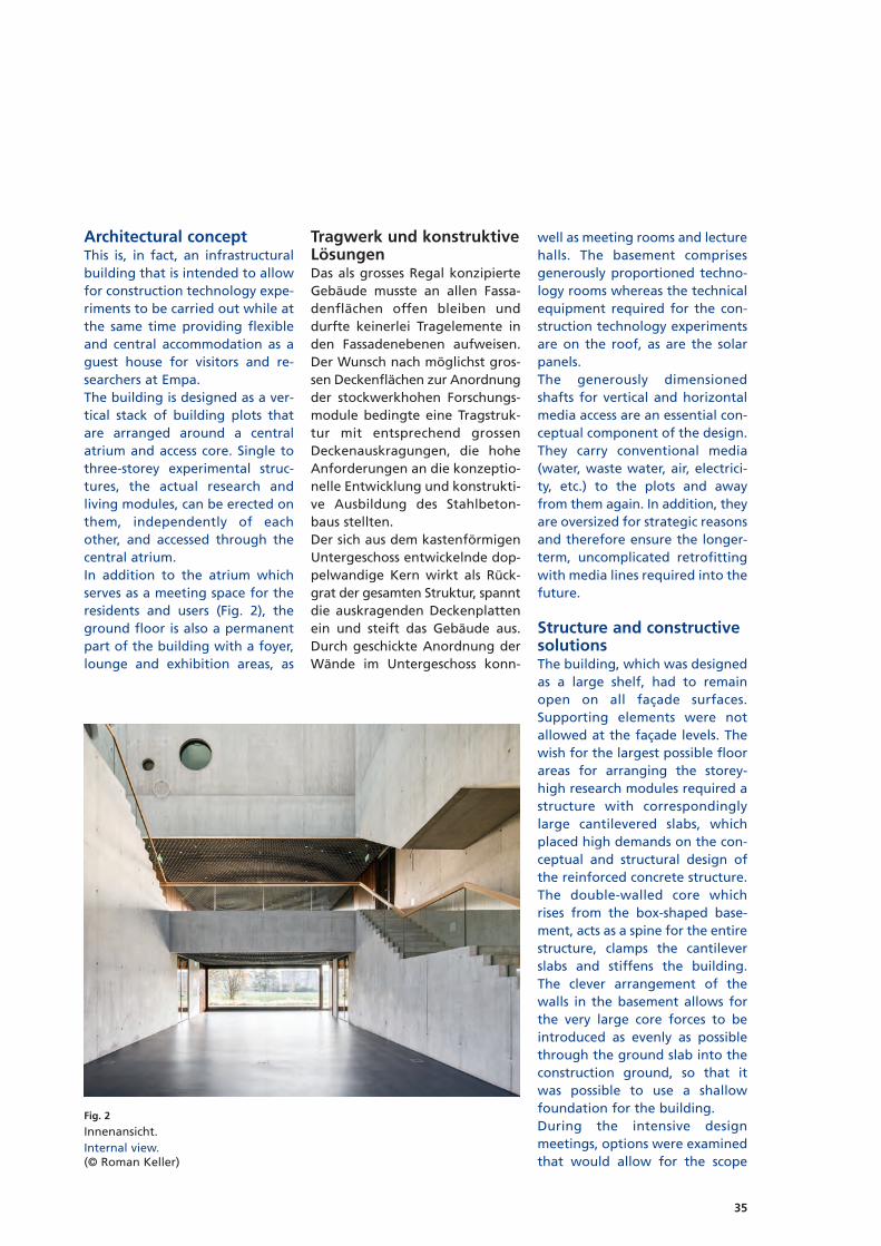
Architectural conceptThis is, in fact, an infrastructuralbuilding that is intended to allowfor construction technology expe-riments to be carried out while atthe same time providing flexibleand central accommodation as aguest house for visitors and re -searchers at Empa. The building is designed as a ver-tical stack of building plots thatare arranged around a centralatrium and access core. Single tothree-storey experimental struc-tures, the actual research andliving modules, can be erected onthem, independently of eachother, and accessed through thecentral atrium. In addition to the atrium whichserves as a meeting space for theresidents and users (Fig. 2), theground floor is also a permanentpart of the building with a foyer,lounge and exhibition areas, as
Tragwerk und konstruktiveLösungenDas als grosses Regal konzipierteGebäude musste an allen Fassa -denflächen offen bleiben unddurfte keinerlei Tragelemente inden Fassadenebenen aufweisen.Der Wunsch nach möglichst gros-sen Deckenflächen zur Anord nungder stockwerkhohen Forschungs -module bedingte eine Tragstruk -tur mit entsprechend grossenDeckenauskragungen, die hoheAnforderungen an die konzeptio-nelle Entwicklung und konstrukti-ve Ausbildung des Stahlbeton -baus stellten.Der sich aus dem kastenförmigenUntergeschoss entwickelnde dop-pelwandige Kern wirkt als Rück -grat der gesamten Struktur, spanntdie auskragenden Deckenplattenein und steift das Gebäude aus.Durch geschickte Anordnung derWände im Untergeschoss konn-
well as meeting rooms and lecturehalls. The basement comprisesgenerously proportioned techno-logy rooms whereas the technicalequipment required for the con-struction technology experimentsare on the roof, as are the solarpanels. The generously dimensionedshafts for vertical and horizontalmedia access are an essential con-ceptual component of the design.They carry conventional media(water, waste water, air, electrici-ty, etc.) to the plots and awayfrom them again. In addition, theyare oversized for strategic reasonsand therefore ensure the longer-term, uncomplicated retro fittingwith media lines required into thefuture.
Structure and constructivesolutionsThe building, which was designedas a large shelf, had to remainopen on all façade surfaces.Supporting elements were notallowed at the façade levels. Thewish for the largest possible floorareas for arranging the storey-high research modules required astructure with correspondinglylarge cantilevered slabs, whichplaced high demands on the con-ceptual and structural design ofthe reinforced concrete structure.The double-walled core whichrises from the box-shaped base-ment, acts as a spine for the entirestructure, clamps the cantileverslabs and stiffens the building.The clever arrangement of thewalls in the basement allows forthe very large core forces to beintroduced as evenly as possiblethrough the ground slab into theconstruction ground, so that itwas possible to use a shallowfoundation for the building.During the intensive design meetings, options were examinedthat would allow for the scope
Fig. 2
Innenansicht.Internal view.(© Roman Keller)

36
ten die sehr grossen Kernkräftemöglichst gleichmässig durch dieBodenplatte in den Baugrundeingeleitet werden, so dass dasGebäude flach fundiert werdenkonnte.Anlässlich der intensiven Konzept -besprechungen wurde nach Mög -lichkeiten gesucht, den Umfangund die Tiefe der Nutzflächenweiter zu vergrössern, was letzt-lich zum Abweichen von einerrein prismatischen Gebäudefigurführte. Durch die stockwerkweiseverschränkte Anordnung der imGrundriss polygonal verlaufen-den Deckenränder wurde es näm-lich möglich, Nutzflächen zugenerieren, die nicht mehr alleindurch die statischen Auskragun genbegrenzt sind. Infolge der aufauskragenden Wandscheiben ele -menten hängenden beziehungs-weise aufgelegten Deckenberei -chen konnte zum Teil auf strengübereinanderliegende Wände ver -zichtet werden und es konnten sostockwerkweise alternierend De -ckenbereiche entwickelt werden,deren nutzbare Auskragung grös-
and the depth of the usable spaceto be expanded, which ultimatelyled to the deviation from a purelyprismatic building shape. The sto-rey-wise interlocking arrange-ment of the polygonal slab edgesin the floor plan made it possibleto generate usable space that isno longer limited solely by thestructural cantilevers. As a result ofthe slab areas that are suspendedfrom or laid on cantilevered wallpanels, it was possible to partlydispense with walls placed strictlyon top of each other and there -fore to develop alternating slabareas, floor by floor, where theusable cantilever is larger than itsstructural cantilever (Fig. 3).The resulting structural challengesare evident in Figure 4. These areon the one hand the high shearstresses of the slabs in the areasof the wall ends and on the otherhand the deflections at the slabedges. To avoid a punching shearfailure of the slabs near the wallends, the arrangement of a localshear reinforcement was indis-pensable. The punching shear
ser ist als die zugehörige statischeAuskragung (Fig. 3). Die sich daraus ergebenden trag-werkstechnischen Herausforde -rungen sind in Figur 4 ersichtlich.Es sind einerseits die grossenSchubbeanspruchungen der De -cken in den Bereichen der Wand -enden und andererseits die Durch -biegungen an den Deckenrän dern.Um ein Durchstanzversagen derDecken im Bereich der Wand -enden zu vermeiden, war die An -ordnung einer lokalen Schubver -stärkung unerlässlich. Mit Bügel -bewehrung allein konnte derDurchstanzwiderstand der 55 bis60 cm starken Obergeschoss de -cken unter maximal 6,5 MN nichtgewährleistet werden. Es wurdenspezielle in der Sichtbeton kon -struktion integrierte Stahlpilzeentwickelt, die eigens für diesenBau konstruiert wurden. Wie ausFigur 5 ersichtlich ist, wurdendiese Durchstanzpilze mit weite-ren in den Beton integriertenStahlelementen ergänzt, die dieFunktion kräftiger Bewehrungenübernehmen. Eingebaut wurden
Fig. 3
Tragstruktur.Structure.(© Roman Keller)

37
resistance of the 55 to 60 cm thickupper floor slabs below 6.5 MNmaximum could not be guaran-teed with stirrup reinforcementalone. Special steel mushroomsintegrated into the exposed con-crete structure were developed,which were specially designed forthis building. As can be seen inFigure 5, these mushroom headswere expanded with other steelelements integrated into the con-crete which assume the functionof strong reinforcements. Heavycompressive reinforcements ofsolid round steel were installed,which introduce the above-men-tioned large slab loads into thewalls by means of shear connec-tors. The cantilevered wall elements,at which a concentrated slab loadof approx. 6.5 MN is introducedat both the top and bottom, alsohad to be fitted with prestressingcables to absorb the tensile forcesfrom the lower slab. The lowersteel mushrooms together withthe rising round steels were sup-plemented with strong steel brack -
schwere Druckbewehrungen ausVollrundstahl, die die erwähntengrossen Deckenlasten über Kopf -bolzendübel in die Wände einlei-ten. Die auskragenden Wandele men te,an denen sowohl unten als auchoben eine konzentrierte Decken -last von rund 6,5 MN eingeleitetwird, mussten zusätzlich mitSpannkabeln versehen werden,um die Zugkräfte aus der unterenDecke aufzunehmen. Die unterenStahlpilze wurden zu sammen mitden aufgehenden Rundstählenderart mit kräftigen Stahllaschenund Ankerplatten ergänzt, dassdie geneigten Spannkabel mitdem integralen Stahlbauteil ver-bunden werden konnten, waseinen sehr direkten und elegan-ten Kraftfluss in den extrem hochbeanspruchten Knotenbereichenermöglicht, wie die Modellierungmit dem kontinuierlichen Span -nungsfeld eindrücklich illustriert(Fig. 6). Vier weitere als Bügel -bewehrung wirkende Spannkabelerhöhen den Schubwiderstandder Wand schei ben.
ets and anchor plates in such away that the inclined prestressingcables could be connected to theintegral steel component, whichenables a very direct and elegantforce flow in the extremely highlystressed node areas, as is impressi-vely illustrated by the modellingwith the continuous stress field(Fig. 6). Four additional prestress -ing cables functioning as stirrupreinforcements increase the shearresistance of the wall panels. The second major challenge wasto control the deformation of theslabs due to their considerableprojections of up to about tenmetres over the corner diagonals.On the one hand, the large liveloads of 10 to 12 kN/m2 that hadto be taken into account and onthe other hand the respectabledead weight of the slabs, madethe design of the slabs with areinforcement alone appear inap-propriate, as especially creep de -formations, which cannot be clearly compensated by means ofa superelevation of the slab, areproblematic. For this reason, the
6,7 m
18,5 m
9,5 m
12,5 m
9,2 m
Fig. 4
TragwerkstechnischeHerausforderungen.Structural challenges.
Fig. 5
Speziell konfektionierte, in den Betoneingelegte Stahlelemente.Specially developed steel elementsinserted into the concrete.

38
Die zweite grosse Herausfor de -rung bestand in der Kontrolle derVerformungen der Decken infol-ge ihrer beträchtlichen Auskra -gun gen von bis zu rund zehnMetern, über die Eckdiagonalengemessen. Einerseits die grossenzu berücksichtigenden Nutzlastenvon 10 bis 12 kN/m2 und ander-seits die respektablen Eigenlastender Decken liessen deren Ausbil -dung mit ausschliesslich schlafferBewehrung als wenig zweckmäs-sig erscheinen, sind doch insbe-sondere die Kriech verformungen,
slabs were consistently prestressed,whereby the 1900 kN flat cableswere guided in such a way thatthe permanent loads are largelycompensated by the deviatoricforces of the prestressing cablesand as a result neither elastic norcreep deformations occur underpermanent loads. In addition, theprestress considerably increasesthe rigidity of the concrete slabsand therefore reduces the de for -ma tion in the service state underthe high live loads. In this way, italso increases the punching shearresistance of the slabs as a resultof the lower rotations above thecolumns, on the one hand, and asa result of the effect of the in -clined and curved cables near thecolumns on the other hand,which can therefore introducetheir deviatoric forces di rectlyinto the support. Notwith stand -ing this, the critical areas of theslabs were fitted in addition witha stirrup reinforcement. Takinginto account the above-described
die nicht eindeutig mit einerDeckenüberhöhung kompensiertwerden können, problematisch.Aus diesem Grund wurden dieDecken konsequent vorgespannt,wobei die 1900 kN-Flachkabel sogeführt wurden, dass die ständi-gen Lasten weitgehend durch dieUmlenk kräfte der Vorspannungkompensiert werden und somitweder elastische noch Kriech -verfor mun gen unter ständigenLasten auftreten. Zudem erhöhtdie Vor span nung die Steifigkeitder Beton platten beträchtlich undreduziert entsprechend die Ver -for mungen im Gebrauchszustandunter den hohen Nutzlasten.Dabei vergrössert sie auch denDurchstanz widerstand der De -cken infolge der geringeren Rota -tionen über den Stützen einer-seits, und andererseits durch denEinfluss der geneigten und ge -krümmten Kabel im Bereich derStützen, die somit ihre Umlenk -kräfte direkt ins Auflager einlei-ten können. Nichtsdesto trotz
Bauherrschaft/OwnerEmpa – Materials Science & Techno -logy, DübendorfArchitekt/ArchitectGramazio Kohler Architects, ZürichBauingenieur/Civil engineerDr. Schwartz Consulting AG, ZugDr. Neven Kostic GmbH, ZürichBauausführung/ContractorStreuli Bau AG, Kilchberg
Fertigstellung/Completion2016
Fig. 6
Kraftverlauf in den hochbeanspruchtenauskragenden Wandelementen: a) Bewehrung und Vorspannung, b) kontinuierliches Spannungsfeld, c) Plandarstellung.Force curve in the highly stressed canti -levered wall elements: a) reinforcement and prestressing, b) continous stress field, c) plan.
(a) (b)
(c)

39
criteria, the geometry of thecables was carefully developedand meticulously implementedon the building site, both in thefloor plan and in the sec tion (Fig.7).
Concluding remarksThe structure of the research build -ing Empa-NEST placed considera-ble demands on the planning andimplementing teams. Thanks to apurposeful and committed inter-disciplinary collaboration rightfrom the initial design phase, thevery strong relationship of trustboth among the planners and visà vis the clients, and the conside-rable commitment and mutuallyrespectful interaction of everyoneinvolved in the implementationphase, the considerable technicaland construction challenges weremastered in a very professionalmanner.
wur den die kritischen Be reicheder Decken zu sätzlich mit einerBügelbe weh rung versehen. UnterBerück sichtigung der be schrie be -nen Kriterien wurde die Geo me trieder Kabel sowohl im Grundriss alsauch im Schnitt sorgfältig plane-risch entwickelt und minutiös aufder Baustelle umgesetzt (Fig. 7).
SchlussbemerkungenDas Tragwerk des Forschungs -gebäudes Empa-NEST stellte sehrhohe Anforderungen an die Pla -nenden und die Ausfüh renden.Dank bewusster und engagierterinterdisziplinärer Zusammen ar -beit ab der ersten Konzeptphase,dem sehr starken Vertrauens -verhältnis sowohl der Planendenuntereinander als auch mit derBauherrschaft sowie dem grossenEinsatz und dem respektvollenUmgang aller Beteiligten in derAusführungsphase konnten diegrossen technischen und bauli-chen Herausforderungen souve-rän gemeistert werden.
Autor/Author
Joseph SchwartzProf. Dr. sc. techn., dipl. Bauing. ETHDr. Schwartz Consulting AGCH-6300 [email protected]
Literatur/Literature[1] www.gramaziokohler.com[2] Schwartz J., Kostic N.; Solides
Rückgrat, TEC 21 22/2016, 34–37
Fig. 7
a) Vorspannkonzept der Decken sowie b) deren bauliche Umsetzung.a) Prestress concept for the slabs and b) its implementation.
(b)(a)

40
EinleitungBei unserem Entwurf für einenSportkomplex mit einer Wett -kampfhalle für 2000 Zuschauerund einer zusätzlichen Trainings -halle haben wir aus städtebauli-chen Gründen die zwei Hallengestapelt angeordnet. Die Trai -ningshalle steht verdreht auf demDach der Wettkampfhalle. Diedadurch entstehende kreuzförmi-ge Figur markiert den prägnan-ten Terrainversatz zwischen dertiefer liegenden Könizstrasse unddem dazu um vier Meter erhöh-ten Plateau der Aussen sport -felder. Das grosse Dach der Halleschliesst niveaugleich an dieAussenanlagen an, während diewesentlich kleinere Trainingshalledarauf als eigenständiger Bau -körper in Erscheinung tritt. Diese
IntroductionIn our design concept for a sportscomplex with a competition arenafor 2000 spectators and an addi-tional training hall, we stackedone hall on the other for urbanplanning purposes. The traininghall sits on the roof of the compe-tition arena at an angle. Theresulting cross-shaped figuremarks the concise terrain offsetbetween the lower-lying roadand the plain of the playingfields, four metres higher. Thelarge roof of the arena connectsto the outdoor facilities on thesame level, while the considerablysmaller training hall above givesthe appearance of an indepen-dent structure. This distributionof volumes is decisive for the full-scale and urban integration of the
Aufteilung der Volumina ist ent-scheidend für die masstäbliche undstädtebauliche Integration desnicht unbeträchtlichen Gesamt vo -lumens in die nähere Umge bung.Die kompakte Kubatur hält grosseBereiche der Parzelle unbe baut,die so für die Aussenanlagen undökologischen Ausgleichsmass nah -men zur Verfügung stehen (Fig. 1).
Architektonisches KonzeptDie beiden Seitenwände der Trai -ningshalle dienen als grosse Über -züge für die Überspannung derdarunterliegenden Arena. Struk -tu rell erfahrbar wird dies vorallem in der Tragrichtung der De -ckenträger der Wettkampf halle:aufgrund der Überzüge spannensie nicht quer zur Hallenaus rich -tung – was normal wäre – son-
Sporthallen WeissensteinSports halls Weissenstein
Christian Penzel, Martin Valier
Fig. 1
Ansicht der gestapelten Hallen mit äusserer Erscheinung der Tragstruktur.View of the stacked halls with external appearance of the structure.(Foto: Dominique Marc Wehrli)

41
not inconsiderable total volumeinto the adjacent surroundings.The compact cubage means thatlarge swathes of the site remainundeveloped and are thereforeavailable for outdoor facilitiesand ecological compensatorymeasures (Fig. 1).
Architectural conceptThe two side walls of the traininghall serve as large upstand beamsfor the span of the arena below.This becomes structurally tangibleabove all in the supporting direc-tion of the ceiling beams of thecompetition arena: due to theupstand beams, they do not spantranseversely to the direction ofthe hall, which would be normal,but longitudinally to it. Duringthe first project phase, the over-
dern längs dazu. In der erstenProjektphase war die obenliegen-de Brückenkonstruktion als Fach -werk noch direkt ablesbar. Im Zugeder Überarbeitung haben wir diezwei grossen, längs gerichtetenFachwerke jedoch durch Scheibenauf einer Reihe von V-förmigenStützen ersetzt. Die Fachwerk trä -ger werden sozusagen selektivvergossen, die plastisch hervorge-hobenen V-Stützen weisen aufihren Ursprung zwar noch hin,erhalten aber eine gewisse Auto -nomie. Die räumliche Entwicklung hatdabei an Klarheit gewonnen undist verstärkt in die Durchbildungder Konstruktion eingeflossen. Sostehen die beiden Hallen nichtnur konstruktiv, sondern auchräumlich und hinsichtlich der
head bridge construction was stilldirectly recognisable as a truss.However, as the design work pro-gressed, we replaced the twolarge, longitudinal trusses withpanels on a row of V-shapedcolumns. The beams of the trusswere “selectively” cast, so tospeak. The clearly emphasised V-shaped columns still point to theirorigin, but have a certain autono-my. In this way, the clarity of the spa-tial development was enhancedand flowed to a greater extentinto the design of the structure.The two halls are therefore in adialectic relationship to eachother not only from a structuralpoint of view but also spatiallyand with regard to lighting. Thetraining hall is open to the sur-
Fig. 2
Sicht in Wettkampfhalle mit Hauptstütze und Trainingshallemit statisch aktivierter Aussenwand.View within the competition arena with main column andtraining hall with structurally activated external wall.(Foto: Dominique Marc Wehrli)
Bauherr/OwnerSporthallen Weissenstein AGGeneralplaner, Architekt undBauingenieur/General planner, architect and civil engineerPenzel Valier AG, ZürichBauausführung/ContractorMarti AG, Bern
Fertigstellung/CompletionAugust 2014

42
Licht führung in einem dialekti-schen Verhältnis zueinander. DieTrainingshalle ist mit einem um -laufenden Lichtband dreiseitigzur Umgebung geöffnet underhält mit den darüberliegenden,hohen Umfassungswänden eine«Raumkappe», deren Volumenvon Oberlichtern aktiviert wird.Im umgedrehten Verhältnis ent-wickelt sich die Wettkampfhalle.Während auch hier ein dreiseiti-ges Lichtband die Wandelebenein die Umgebung öffnet, ist dasSpielfeld in das Terrain eingegra-ben. Die Haupttribüne verläuft vonder Wandelebene in einer grossenGeste bis hinunter auf das abge-senkte Spielfeld. Damit wird derSchnittverlauf vom Gelände ni veauder Aussensportanlagen über dieTribünen zur Senke des Hallen -bodens und wieder hinauf auf dieEbene des Vorplatzes mit einergrossen innerräumlichen Schnitt -figur inszeniert. Beide Hallen wei-sen demnach eine prägnanteräum liche Ableitung ihrer Stape -lung auf und spiegeln damit diestädtebauliche Figur im Innerenwider. Das Haupttragwerk aus Trägernund Scheiben wird über die Akti -vierung der Decken und die weni-gen inneren Wandscheiben aus-gesteift und stabilisiert. Mit der
rounding area on three sidesthanks to strip windows and,together with the overlying highperimeter walls, has a “room cap”,the volume of which is activatedby sunlights. The competitionarena developed in an inverseratio. While in this case stripwindows on three sides also openup the building from the accessarea to the stands towards thesurrounding area, the playingfield is embedded in the terrain.The main stand runs in a grandgesture from the access area tothe stands down to the sunkenplaying field. In this way, the sec-tion course from the terrain levelof the outdoor sports facilitiesthrough the stands, down to thehollow of the hall floor and backup to the level of the forecourt isstaged with a large interior sec-tional figure. Consequently, bothhalls demonstrate a concise spa -tial derivation of their stackingconcept and therefore reflect theurban figure in the interior. The main structure with beamsand panels is stiffened and stabi -lised through the activation of theslabs and the few internal shearwalls. With this change from trusses to simple, space-definingpanels, we have attempted toenhance the urban and spatial
Änderung vom Fachwerkträgerzu einfachen, raumdefinierendenScheiben haben wir versucht, diestädtebaulichen und räumlichenQualitäten zu stärken und dieohnehin schwierige «Erklärung»des Tragverhaltens zurückzuneh-men (Fig. 2, 4).
Statisches KonzeptAusgangslage GeologieDer Bauperimeter der Sporthallenliegt im Bereich einer ehemaligenKiesdeponie. Die Auffüllung derDeponie erfolgte über Jahreunkontrolliert und lose mit was-sergesättigtem Silt und Ton. Daseingeschlossene Meteor- wieauch Porenwasser konnte sichüber die teils Jahrzehnte andau-ernde Lage rung nicht entwässern,obwohl die Grubensohle abUnterkante der Schüttung hochdurchlässig war. Der Baugrundwar daher auf sämtlichen Lagenohne Material ersatz oder denEinsatz von Ma trat zen wederbegeh- noch befahr bar.
Fundation/GeologieIn der Wettbewerbsphase stelltenwir früh fest, dass Fundations kon -zepte mit wenigen, dafür aberkräftigen Fundamenten zu keinemwirtschaftlichen Nachteil führen.Zur Ausführung gelangte schliess-
Fig. 3
Innenraum Wettkampfhalle mit längs spannenden Trägern und rückwär -tigen Oberlichtern.Interior of competition arena with longitudinal beams and rear skylights.(Foto: Dominique Uldry)

43
qualities and to dispense with an“explanation” of the structuralbehaviour, that would have beendifficult in any event (Fig. 2, 4).
Structural conceptInitial situation geologyThe construction perimeter of thesports halls is in the area of a for-mer gravel landfill. The landfill wasfilled over the years, unregulatedand freely, with water-saturatedsilt and clay. The trapped rain -water and pore water could notdrain during the storage periodwhich was at times decades long,even though the pit bed from thelower edge of the infill washighly porous. As a result, it wasnot possible either to walk on thesubgrade or drive on it at anylevel without replacing materialor using mattresses.
Foundation/geologyWe discovered early on in the com -petition phase that foundationconcepts with few but strongfoundations were not economi-cally disadvantageous. Ultimately,a solution involving four pile capswith a total of 14 large boredpiles, diameter 1180 mm (5 no.)and diameter 1500 mm (9 no.)and a length of about 2 m in eachcase was chosen. The piles are
lich eine Lösung mit vier Pfahl -ban ketten mit total 14 Grossbohr -pfählen, Durchmesser 1180 mm (5Stück) und Durchmesser 1500 mm(9 Stück) und einer Länge von je -weils etwa 20 m. Zur Vermei dungeiner Gruppenwirkung bei derzugleich angestrebten, konzen-trierten Lasteinleitung über mög-lichst kompakte Pfahlbankettesind die Pfähle je 7 Grad aus derVertikalen ab Kopf nach aussengeneigt. Die Krafteinleitung er -folgt über die Mantelreibung derleicht geneigten Pfähle. Kleinere,periphere Lasten werden überzusätzliche, duktile Gusspfähleabgeleitet.
Struktur Die beiden Längswände der obe-ren Trainingshalle, 40 und 50 cmstark, werden als vorgespannteWandscheiben ausgebildet unddienen als grosse Überzüge fürdas Dach der darunterliegendenWettkampfhalle. Sie liegen je aufzwei massiven Hauptstützen. DerMomentenverlauf in den Wand -scheiben mit einem grossen Feldüber knapp 34 m und einer 17 mlangen Auskragung erfordertezur Vermeidung innerer Zwän gun -gen eine ausgeklügelte Kabelfüh -rung mit bis zu 12 Kabeln 12-06.Die hier erwähnten vier Haupt -
inclined 7 degrees from the verti-cal to the outside, from the tip, toavoid a group effect while at thesame time achieving the desiredconcentrated load introductionvia the most compact pile capspossible. The force introduction isvia surface friction with theslightly inclined piles. Smaller,more peripheral loads are trans-ferred via additional, ductile castiron piles.
Structure The two longitudinal walls of theupper training hall, 40 and 50 cmthick, are designed as prestressedshear walls and serve as largeupstand beams for the roof of theunderlying competition arena.They rest each on two solid maincolumns. The moment distributionin the shear walls with a large spanof just under 34 m and a 17 mlong cantilever, required intricatecable routing with up to 12 cables12-06, to avoid internal restraints.The four main columns mentionedhere transfer the forces from thepanels directly into the pile caps. The 67 m, extremely long, longi-tudinal beams of the competitionarena with a structural height of2.1 m and each with a cable 19-06, are only hanging on the shearwalls of the overlying training
Fig. 4
Innenraum Trainingshalle mit quer spannenden Trägern, Oberlichtern undseitlicher Verglasung.Interior of training hall with transverse beams, skylights and side glazing.(Foto: Dominique Uldry)

44
stützen leiten die Kräfte aus denScheiben direkt in die Pfahlban -kette ab. Die mit 67 m enorm langen, längslaufenden Träger der Wettkampf -halle mit einer statischen Höhevon 2,1 m und je einem Kabel 19-06 sind nur an den Wandscheibender darüberliegenden Trainings -halle aufgehängt und auf einerSeite aufgelagert. Die Aufhän gungüber vertikal vorgespannte Swiss-Gewi-Stangen in die Wandschei -ben der Trainingshalle wird vonder unteren Wettkampfhalle ausoptisch nicht wahrgenommen. Das kritische Schwingungsverhal -ten der über diesen längs laufen-den Trägern liegenden Decke derWettkamphalle, die zugleich auchden Boden der Trainingshalle dar-stellt, wurde aufwendig nachge-wiesen. Für die Modellierungwurden die Träger monolithischmit den Decken verbunden. DieMehrfeldträger weisen unter-schiedliche Spannweiten auf, ihreLagerung ist in den darüberlie-genden Wandscheiben wie auchder einen Stütze als eingespanntangenommen. Die Auflasten ent-sprechen exakt der unterschiedli-chen Nutzung. Ferner wurde dasSystem aufgrund der Vorspan nungaller Teile als ungerissen angenom -men. Dadurch resultierte rech ne -risch die erste unkritische, tiefsteEigenfrequenz bei 12,3 Hz, wassich im ausgeführten Projekt an -hand einer Kontrollmessung auchbestätigen liess.Die 1,35m hohen Träger des Dachsder Trainingshalle sind als Zwei -feld träger ausgelegt und ebenfallsje mit einem Kabel 19-06 über -drückt. Sie spannen knapp 30 mquer zur Trainingshalle und ruhenin den einleitend erwähntenWand scheiben. Das zweite Feldder Träger über weitere 8 m ist ineine dritte, schlaff bewehrteWand scheibe eingebunden unddort gegen Abheben fixiert.Die horizontale Aussteifung er -folgt sowohl über die Decke derWettkampfhalle als auch überden Boden der Wandelebene. Dasdaraus resultierende Kräftepaarwird jeweils über vertikale Rippenin die rückwärtigen, mit der Hin -terfüllung ballastierten Pfahlban -
Fig. 5
Bau der Seitenwände Trainingshalle.Constructing the side walls of the training hall.(Foto: Dominique Uldry)
0 7,5 15 37,5
Grundriss
A
A
B
Querschnitt A–A
Längsschnitt B–B
Spannkabel
B
1
1 Hauptstützen2 Wandscheiben Trainingshalle3 Träger Wettkampfhalle
4 Träger Trainingshalle5 Masseschwerpunkte6 Rückverankerung7 Pfähle
1
11
5
5
22
7
6 6
11
6
7
4
2
3
4
2
3
2
Fig. 6
Statischer Aufbau mit Darstellung der Kräfte,Spannkabelverläufe und Masseschwerpunkte.Structure with representation of forces, tendonsand centres of mass.

45
hall and supported on one side.The mounting via vertical pre-stressed Swiss Gewi rods in theshear walls of the training hall isnot visible from the underlyingcompetition arena. The critical vibration behaviour ofthe slab above these longitudinalbeams in the competition arena,that is also the floor of the train -ing hall, was verified extensively.For the modelling, the beamswere connected monolithicallywith the slabs. The multi-spanbeams have varying spans, theirbearing is assumed to be clampedin the shear walls above as well asin one of the supports. The loadscorrespond precisely to the diffe-rent types of use. Furthermore,the system was assumed to benon-cracked due to the prestres-sing of all members. This resultedin, mathematically, the first uncri-tical, lowest natural frequency of12.3 Hz, which was then confirmedby way of controlled measure-ment in the executed project.The 1.35 m high beams of theroof of the training hall are de -signed as double-span beams andeach with a cable 19-06 underpressure. They span almost 30 mtransversely to the training halland lie in the shear walls men -tioned at the beginning. Thesecond span of the beam over afurther 8 m is integrated into areinforced shear wall and fixedthere against lifting. Horizontal stiffening is achievedboth via the roof slab of the com-petition arena and via the floorof the access area to the stands.The resulting pair of forces is eachreleased via vertical ribs into therear pile cap, which is ballastedwith backfill. The tension cablesin the roof slab transfer the hori-zontal force components of theinclined main columns. In order to compensate vibrationdifferences in the event of anearthquake due to varying cen-tres of mass of the training hall tothe clamping horizon, the fronttwo main columns are freelymovable horizontally with slidebearing plates on the floor of theground floor. An extensive, heavysupport was required to build the
kette abgegeben. Die in der De -cke liegenden Spannkabel leitendie Horizontalkraftanteile derschrägen Hauptstützen ab. Um Schwingungsdifferenzen imErdbebenfall aufgrund unter-schiedlicher Massenschwerpunkteder Trainingshalle zum Einspann -horizont zu kompensieren, sinddie vorderen zwei Hauptstützenhorizontal frei verschieblich mitGleitlagerplatten auf dem Bodendes Erdgeschosses abgestellt. Für den Aufbau der Struktur wareine umfangreiche, schwere Ab -stützung notwendig (Fig. 5 bis 7).Das Tragwerk konnte seine Funk -tion erst nach dem Aushärten derletzten Betonieretappen, derDecke über der Trainingshalle,integral erfüllen. Bis zu diesemZeitpunkt mussten alle Trägerund Wandscheiben über schwereSpriessungen gesichert werden. Das Spannen der Kabel in denTrägern und Wandscheiben er -folgte erst zum Schluss nach vor-gegebenem Drehbuch. EinzelneKabel mussten dabei über vierEtappen gespannt werden. Dievor dem Absenken erfolgte Null -messung an über 70 Kontroll -punk ten ergab nach Abschlussaller Arbeiten und inklusive derPfahlstauchung eine maximaleEinsenkung von nur 8 mm.
structure (Fig. 5 to 7). The struc -ture could only integrally fulfil itsfunction after the slab over thetraining hall, the final concretestep, had hardened. Up to thatpoint in time, all beams and shearwalls had to be secured withheavy stays. The cables in the beams and shearwalls were only tensioned at theend in accordance with a speci-fied scenario. In this case, somecables had to be tensioned in fourstages. The baseline measure-ment carried out at over 70 con-trol points prior to lowering dis-played a maximum sinking ofonly 8 mm, after the completionof all works and including pilecompression.
Autoren/Authors
Christian PenzelDipl.-Ing. [email protected]
Martin Valierdipl. Ing. [email protected]
Penzel Valier AGCH-8045 Zürich
Fig. 7
Statische Struktur mit Pfählung.Structure with piling.

46
EinleitungGanz im Zeichen der innovations-fördernden Kultur der Fachhoch -schule Nordwestschweiz (FHNW)wird auf das Herbstsemester 2018in Muttenz ein neuer Campus er -öffnet. Er dient als neues Zuhausefür die bis anhin auf 36 Standorteverteilten Hochschulen für Archi -tektur, Bau und Geomatik, LifeSciences, Soziale Arbeit, Pädago -gi sche Hochschule und Trinatio -na ler Studiengang Mechatronikder Hochschule für Technik. Derneue Standort wird mit rund34 500 m2 Hauptnutzfläche derStudien- und Arbeitsort von rund3700 Studierenden und 800 Mit -arbeitenden sein. Im Mai 2011 gewannen pool Ar -chi tekten in Zusammenarbeit mitden Tragwerksplanern SchnetzerPuskas Ingenieure den selektivenProjektwettbewerb mit dem Pro -
IntroductionDriven by a culture at the Uni -versity of Applied Sciences andArts Northwestern Switzerland(FHNW) that promotes innova tion,a new campus will be opened intime for the autumn semester2018 in Muttenz. It will be a newhome to the Schools of Archi -tecture, Civil Engineering andGeomatics, Life Sciences, SocialWork, and Education, and for theMechatronics Trinational course atthe School of Technology, whichto date have been spread across36 locations. The new locationwith its 34,500 m2 of service areawill provide a study and workarea for approx. 3,700 studentsand 800 staff. In May 2011, architects pool Archi -tekten in conjunction with struc-tural engineers Schnetzer PuskasIngenieure won the selective pro-
jekt «Kubuk». Dieses ist geprägtdurch einen kubischen Baukör permit einem minimalen Foot printund einer grosszügigen an ge -gliederten Parkanlage. Der Hauptbau weist mit zweiUntergeschossen, Erdgeschoss undzwölf Obergeschossen eine Höhevon rund 64 m und Grundrissab -mes sungen von 63 m mal 70 mauf, sodass er als Würfel in Er -scheinung tritt. Im Sockelbereichdes Hauptbaus vom Erdgeschossbis zum 3. Obergeschoss sind dieöffentlichen Nutzungen mit Hör -sälen, Aula, Mensa, Bibliothek undDrittnutzungen untergebracht,während sich vom 4. bis zum 12.Obergeschoss Büros, Labors undSeminarräume der verschiedenenFakultäten finden. Das Dachge -schoss wird hauptsächlich fürTechnikanlagen verwendet. DieUntergeschosse umfassen diverse
Ein Hochhaus und ein Hofhaus– das Tragsystem im neuenCampus der FHNW Muttenz A high-rise and a courtyard building – the structural systemof the new FHNW campus building in Muttenz
Stefan Bänziger, Timothy Hafen
Fig. 1
«Kubuk» – der neue Campus der Fachhochschule Nordwestschweiz in Muttenz.“Kubuk” – the new campus building at the University of Applied Sciences andArts Northwestern Switzerland (FHNW) in Muttenz.(© Martin Stollenwerk)

47
ject competition with their pro-ject “Kubuk”. The project is cha-racterised by a cubic building witha minimal footprint and a spa ciousadjoining park. The main building has two floorsat basement level, a ground floorand 12 upper floors and is ap -prox. 64 m in height with floordimensions of 63 m by 70 m, sothat it resembles a cube. The baseof the main building, from theground floor to the 3rd floor, com -prises public spaces with lecturehalls, an auditorium, the canteen,the library and space for thirdparty use, while the 4th to the12th floors comprise the offices,laboratories and seminar roomsof the various faculties. The topfloor is used mainly for technicalequipment. The basement floorscomprise various laboratories andworkshops and also storeroomsand plant rooms. Adjacent to thisis an underground area that is ap -prox. 10 m high and approx. 28 mby 63 m in size with a doublegymnasium, a construction hall,workshops and storage rooms.
Structural conceptThe upper floors are designed asa consistent skeleton construction
Labors und Werkstätten sowieLager und Technikräume. Unter -irdisch angegliedert ist ein rund10 m hohes Volumen mit Abmes -sungen von rund 28 m mal 63 mmit einer Doppelturnhalle, derBau werkshalle, Werkstätten undLagerräumen.
TragwerkskonzeptDie Obergeschosse sind konse-quent in Skelettbauweise mit vierstabilisierenden Erschlies sungs -ker nen, Geschossdecken und vor-fabrizierten Betonstützen konzi-piert. Mit zwei Innenhöfen erge-ben sich im Grundriss ein 14 mbreiter Deckenring entlang derFassade und ein Mitteltrakt. Zu -gunsten einer maximalen Nut -zungs flexibilität sind in einerRichtung jeweils Deckenspann -weiten von 14 m vorhanden, diemit überbetonierten, vorfabri-zierten Rippenplatten überbrücktwerden. In der anderen Richtungentlang der Deckenränder be -trägt das Stützenraster mit einemRandträger 7 m. Die Betonstärkeist unter Berücksichtigung derTrittschallanforderungen so fest-gelegt, dass Bodenbeläge gröss-tenteils direkt im Verbund ausge-führt werden konnten.
with four stabilising access cores,floor slabs and prefabricated con-crete columns. With two court -yards, the floor plan shows a 14 mwide ring of slabs along the façadeand a central wing. To achievemaximum flexibility of use, thereare spans in one direction, each14 m wide, that are bridged withprefabricated ribbed plates witha concrete overlay. In the otherdirection along the edges of theroof, the support grid with oneedge beam is 7 m. The thicknessof the concrete, taking impactsound requirements into account,is determined in such a way thatmost of the floor coverings werelaid directly bonded. On the 4th floor, the inner wing,referred to as the central wing, issupported by a storey-high bridgestructure made in part of discon-tinues shear walls and prestressedin situ concrete flat slabs, to allowfor the atrium below that is over20 m high. The first and secondfloors are supported using thesame principle, allowing for thecreation of a 42 m wide, column-free main entrance. In addition,prestressed flat slabs allow for theconstruction of generous cantile-vered galleries around the court -
Fig. 2
Schnittperspektive des Gebäudes.Cross-sectional perspective of the building.(© pool Architekten)

48
Im 4. Obergeschoss wird der alsMitteltrakt bezeichnete Innen -trakt mit einem geschosshohenBrückentragwerk aus teilweiseaufgelösten Wandscheiben undvorgespannten Ortbetonflach de -cken abgefangen, um darunter einüber 20 m hohes Atrium zu ermög -lichen. Mit dem gleichen Prinzipwerden das erste und zweiteObergeschoss abgefangen, umeinen stützenfreien, 42 m breitenHaupteingang zu schaffen. Vor ge -spannte Flachdecken ermöglichenüber dem Erd- sowie dem 1. und2. Obergeschoss zudem grosszü-
yard above the ground, the firstand the second floors. Together with a monolithic groundslab, slabs and concrete walls, thebasement floors create a rigid boxin which the horizontal stiffeningaccess cores are clamped. In situ bored piles transfer con-centrated loads on the cores andmain columns into the bedrock,which also prevents unusual sub-sidence of the subgrade due todoline formation in karstifiedgipskeuper. Secondary columnsthat only transfer basement floorloads and are not required for theoverall stability of the building,are shallow founded with stripfootings.
Transfer structures The central wing stretches 35 macross the atrium and absorbs theloads of the overlying eightfloors. Its floor slab acts as a ten-sion flange, while the slab overthe 4th floor creates the compres-sion flange. Together with thelateral end walls, they create ahollow rectangular box. Theapprox. 60 cm thick ground slabexhibits strong centric longitu -dinal prestressing for the tensionflange effect. In the transverse
gig auskragende Galerien um denInnenhof. Die Untergeschosse bilden miteiner monolithischen Bodenplat te,Decken und betonierten Wän deneinen steifen Kasten, in dem diehorizontal aussteifenden Er schlies -sungskerne eingespannt sind. Ortbetonbohrpfähle tragen kon-zentrierte Lasten bei den Kernenund Hauptstützen in den Fels un -tergrund ab, wodurch auch aus-sergewöhnliche Einsenkungen desBaugrunds infolge Dolinenbil dungim verkarsteten Gipskeuper ver -mie den werden können. Sekun dä -re Stützen, die nur Untergeschoss -lasten abtragen und nicht für dieGesamtstabilität des Gebäudeserforderlich sind, sind mit Fun da -mentriegeln flach fundiert.
Abfangkonstruktionen Der Mitteltrakt spannt 35 m überdas Atrium und fängt die Lastender darüberliegenden acht Ge -schosse ab. Sein Boden wirkt alsZugflansch, während die Deckeüber dem 4. Obergeschoss denDruckgurt bildet. Zusammen mitden seitlichen Abschlusswändenbilden sie einen rechteckigenHohlkasten. Die rund 60 cm dickeBodenplatte weist für die Zug -
Fig. 3
Lehrgerüst und Krafteinleitungsdetail des Mitteltraktes.Falsework and force introduction detail of the central wing.(© Martin Stollenwerk)
Bauherr/OwnerBau- und UmweltschutzdirektionKanton Basel-Landschaft, vertretendurch das/represented by theHochbauamt, Basel-LandschaftBauausführung/ContractorHRS Real Estate AGArchitekt/Architectpool Architekten ZürichProjektingenieur/Project engineerSchnetzer Puskas Ingenieure AGGesamtleitung/Overall managementPerolini Baumanagement AGLandschaftsarchitektur/LandscapearchitectSchweingruber Zulauf
Fertigstellung/CompletionSommer 2018

49
direction, a parabolic prestress isin serted, in addition, in theground and the slab due to slabstress at a span of 14 m. The cen-tral wing rests with two cornerseach on columns and on thenorth and south cores. Due to theconsiderable shear loads of theside walls, a 45° inclined reinfor-cement is inserted, which mergescontinuously into the adjacentcore walls. A force introductiondetail made of steel was deve -loped around the area of the col -umns, which transfers the forcesthrough shear connectors andwelded reinforcement bars to thesolid steel cores of the column. Due to the clamping between thecores, the ground slab of the cen-tral wing could not be directlyconnected monolithically to theadjoining slabs, as is the case in anormal construction process. Thiswould inevitably have resulted inconcentrated cracks in the sup-port areas due to contractionfrom prestressing, cooling downafter the setting process andshrinkage. In order to avoid theseadverse influences, the groundslab of the central wing on the4th floor had to be concreted andprestressed in advance, while
gurtwirkung eine kräftige zentri-sche Längsvorspannung auf. InQuerrichtung ist aufgrund derPlattenbeanspruchung bei einerSpannweite von 14 m im Bodenund in der Decke zusätzlich eineparabelförmige Vorspannung ein -gelegt. Der Mitteltrakt liegt mit jezwei Eckpunkten auf Stützenrespektive den Kernen Nord undSüd auf. Aufgrund der grossenQuerkraftbeanspruchung der Sei -tenwände ist eine um 45° geneig-te Bewehrung eingelegt, die kon-tinuierlich in die angrenzendenKernwände übergeht. Im Bereichder Stützen wurde ein Kraftein lei -tungsdetail aus Stahl entwickelt,das die Kräfte über Kopfbolzen -dübel und angeschweisste Beweh -rungseisen auf den Vollstahlkernder Stütze abträgt. Aufgrund der Einspannung zwi-schen den Kernen konnte dieBodenplatte des Mitteltraktsnicht dem üblichen Bauablaufentsprechend direkt monolithischmit den angrenzenden Deckenverbunden werden. Dies hätteinfolge der Kontraktionen durchdie Vorspannung, des Abkühlensnach dem Abbindeprozess und derSchwindverkürzungen zwangs -läu fig zu konzentrierten Rissen in
detached from the cores andcolumns. After that, the connec -tions to the core walls and theadjacent storey slabs were carriedout. An impressive, free-standingfalsework was erected in the
Fig. 4
Ansicht des Lehrgerüsts des Mitteltrakts und der um 45° geneigeten Anschlussbewehrung.View of the falsework for the central wing and the 45° inclined connecting reinforcement.(© Martin Stollenwerk)
Fig. 5
Krafteinleitungsdetail im 2. Unter -geschoss der Hauptstützen.Force introduction detail in the 2ndbasement floor of the main columns.(© Martin Stollenwerk)

50
und Stützen vorgängig betoniertund vorgespannt werden. Danachkonnten die Anschlüsse an dieKernwände und angrenzendenGeschossdecken erstellt werden.Um diesen ungewöhnlichen Bau -ab lauf zu ermöglichen, wurde imInnenhof ein imposantes, freiste-hendes Lehrgerüst aufgebaut.Dieses wurde so ausgelegt, dasses das Abfanggeschoss und zweidarüberliegende Geschosse kom-plett abtragen konnte, bevor esselber abgesenkt und entferntwurde.
RippendeckenAufgrund des hohen Installa ti ons -grads der Räume der FHNW unddes Anspruchs an flexible Raum -gestaltung musste ein Decken sys -tem gefunden werden, das sowohlmöglichst grosse, stützenfreieRäume schafft als auch genügendMöglichkeiten für die Haustech -nikinstallationen bietet. Als opti-males System wurden im Spann -bettverfahren vorgespannte Rip -pendecken eruiert. GegenüberFlachdecken sind diese deutlichleichter, was sich positiv auf dieDimensionierung der Decken kon -struktion, aber auch auf die ge -samte vertikale Lastabtragung biszur Pfahlfundation auswirkt. Einekoordinierte Anordnung von Aus -sparungen ermöglichte das Que -ren von Haustechnik leitun geninnerhalb der Rippen, was einOptimum an Raumhöhe ergab.Ein weiterer positiver Aspekt die-ses Deckensystems war ein effi-zienter Bauablauf dank einerRollbewehrung für die oberenBewehrungslagen des Decken -spiegels. Die Rippen wurden imElementwerk mit 8 Litzen (P0,tot =1000 kN) im Spannbettverfahrenerstellt und auf die Baustellegeliefert. Nach dem Versetzenwurden diese mit den angrenzen-den Randunterzügen und demÜberbeton monolithisch ausbeto-niert. Die Rippenplatten wurdenso dimensioniert, dass sich durchdie Überhöhung infolge derVorspannung und dem zusätzli-chen Gewicht des Überbetons imBauzustand keine Durchbiegungergab und keine Spriessung erfor-derlich war.
Fig. 6
Fertige Rippendeckenuntersicht.View of finished ribbed slab from below.(© Martin Stollenwerk)
Fig. 7
Lehrgerüst der vorgespannten Treppen im Atrium der FHNW.Falsework for pretensioned staircases in the atrium of the FHNW.(© Martin Stollenwerk)
den Auflagerbereichen geführt.Um diese ungünstigen Einflüssezu vermeiden, musste die Boden -platte des Mitteltrakts im 4. Ober -geschoss losgelöst von den Ker nen
courtyard, to enable this unusualconstruction process to be carriedout. It was designed so that itcould completely remove the sup-port floor and the two overlying

51
upper floors before it was lower edand removed itself.
Ribbed slabsDue to the high level of installa -tion required for the rooms at theFHNW and the demand for flexi-ble room design, a slab systemhad to be found that allowed forthe creation of rooms that are aslarge as possible and also column-free, and that provided sufficientpossibilities for the building ser-vices installations. It was decidedthat the ideal system involved ribbed slabs prestressed in a pre-stressing bed procedure. Com -pared with flat slabs, they areconsiderably lighter, which has apositive effect on the dimension -ing of the slab construction andalso on the overall vertical loadtransfer to the pile foundation.The coordinated arrangement ofrecesses made it possible to crossbuilding services lines within theribs, which resulted in an opti-mum room height. Another posi-tive aspect of this slab system wasthe efficient progress in construc-tion thanks to a roller reinforce-ment for the upper reinforce-ment layers of the reflected ceil -ing plan. The ribs were manufac-tured at the precast factory with8 strands (P0,tot = 1000 kN) in aprestressing bed procedure anddelivered to the construction site.Once they were set, they weremonolithically concreted to theadjacent edge beams and coveredwith the concrete overlay. Theribbed plates were dimensionedin such a way that there was nodeflection resulting from eleva -tion due to prestressing and theadditional weight of the concreteoverlay in the state of construc -tion, and therefore no stay brac -ing was required.
Prestressed staircasesAnother striking feature of thecampus is the six staircases in theatrium that provide access to thepublic spaces at the university.They stretch for up to 24 m overthe atrium. The strong flangeswith parabolic pretension are con -nected to each other and stabilis edby way of the slender treads. In
Vorgespannte TreppenEin ebenfalls markantes Elementdes Campus bilden die sechsTreppen im Atrium, die die öf -fentlichen Räume der Fachhoch -schule erschliessen. Sie spannenbis zu 24 m weit über das Atrium.Die kräftigen Wangen mit einerparabelförmigen Vorspannungwerden durch die filigranen Trittemiteinander verbunden und sta-bilisiert. Um die Durchbiegungenbei den Treppenauflagern aufden auskragenden Galeriedeckenzu minimieren, wurden bei denGalerieumgängen Brüstungen inOrtbeton vorgesehen. Aufgrundder hohen Anforderungen an dieQualität der Treppen wurden dieTritte vorgefertigt und im Werkgeschliffen. Die Wangen wurdenmit Lehrgerüsten vor Ort ge -schalt, die vorgefertigten Tritte indie Schalung versetzt und in dieWangen einbetoniert.
Nougat – Kunst am BauIn in der Mitte des Atriums throntzudem das Werk «Nougat (wietief ist die Zeit?)» der KünstlerinKatja Schenker, ein 10,5 m hoherMonolith mit einer 2 x 2 m messen -den quadratischen Grund flä che.
order to minimise deflections inthe staircase supports on the can-tilevered gallery slabs, balustradesmade from in-situ concrete wereplanned for the gallery corridors.Due to the high standard of qua-lity required for the staircases, thetreads were prefabricated andsanded in the factory. The flangeswere formed on site using false-works, and the prefabricated treadswere placed in the formwork andconcreted into the flanges.
Nougat – art in architectureAt the centre of the atrium standsthe sculpture “Nougat (how deepis time?)” by the artist KatjaSchenker, a 10.5 m high monolithwith a 2 x 2 m square base.
Fig. 8
«Nougat (wie tief ist die Zeit?)» von Katja Schenker im Atrium der FHNW.“Nougat (how deep is time?)” by Katja Schenker in the atrium of the FHNW.(© Martin Stollenwerk)
Autoren/Authors
Stefan Bänzigerdipl. Ing. [email protected]
Timothy Hafendipl. Ing. [email protected]
Schnetzer Puskas Ingenieure AGCH-8003 Zürich

52
EinleitungDas Fernwärmenetz der Stadt St.Gallen versorgt mehr als 11 000Wohnungen und Betriebe mitWärmeenergie zu Heizzwecken.Im Rahmen der Energiestrategie2050 der Stadt St. Gallen ist einwesentlicher Ausbau des Fern wär -menetzes geplant. Im Zuge derAusbauphase 1 wurde die Fern -wärmezentrale Waldau errichtet,die als Unterstation für die Vertei -lung der Heizenergie aus demKehrrichtheizkraftwerk dient. Neben den Netzpumpen beher-bergt die Fernwärmezentrale ins-besondere zwei mit Heizöl betrie-bene Spitzenlastheizkessel mit je16 MW Leistung, ein Tanklagerfür 450 000 l Öl sowie einen150000 l fassenden Warmwasser -speicher, um den Not- und Spitzen -bedarf des Fernwärmevebunds zudecken. Zwei Querraster der Hallewerden ausserdem für die Lage -rung von bis zu 600 t Tausalz fürden Strassenwinterdienst desTief bauamts der Stadt St. Gallengenutzt.
GesamtkonzeptionDas Projekt, das beim Studien -auftrag nach Präqualifikation denZuschlag erhalten hatte, basiertauf einem Systembaukonzept, dasvon den St. Galler Stadtwer ken anverschiedenen Standorten undfür unterschiedliche Nutzungeneingesetzt werden kann. DasHallentragwerk mit längsseitigerweiterbarem Grundraster von 6mal 6 Metern ermöglicht denStadtwerken in unterschiedlichenstädtischen Situationen eineneigenständigen und wiederer-kennbaren baulichen Auftritt.Die Primärtragstruktur ist aushochfesten vorfabrizierten Beton -elementen gefertigt, was bei denAusfachungen je nach NutzungGestaltungsspielraum offenlässt.Um die Schallschutzanfor derun gender im Siedlungsraum platzierten
IntroductionThe district heating network ofthe city of St. Gallen provides ther -mal energy for heating to over11,000 apartments and businesses.A significant extension of thedistrict heating network is underway as part of the “Energy Stra te -gy 2050” of the city of St. Gallen.Extension Phase 1 consists of theconstruction of the Waldau dis -trict heating centre, which servesas a substation for the distribu -tion of the thermal energy gene-rated in the waste-to-energy plant. To meet emergency and peak de-mands, the district heating centrehouses not only the heat pumpsbut also two 16-MW fuel-oil-powered peak load boilers, a450,000-litre oil depot, and a150,000-litre hot-water tank. Twosections of the hall are used tostore up to 600 t of deicing saltfor the winter road services of theSt. Galler Stadtwerke (Civil Engi -neer ing Department of St. Gallen).
Global conceptThis project, which was chosenbased on a study contract afterpre qualification, is based on amo dular construction concept,which can be applied by St. GallerStadtwerke at various locationsand for a variety of uses. The hallconstruction, which consists of amodular grid of 6 by 6 metres andcan be extended lengthwise,allows the St. Galler Stadtwerketo achieve a distinct and recogniz-able architectural look at variouslocations in the city. The primary load-bearing struc -ture consists of prefabricated high-strength concrete elements, whichcan offer a flexible design of theinfill walls, depending on theintended use. In order to meet thenoise protection requirements ofthe facility, which is located in aresidential area, the infill walls ofthis construction were made of
Anlage zu erfüllen, wurden dieAusfachungen in der vorliegen-den Konfiguration in Massiv bau -weise gewählt, wobei hierfürMischabbruch-Recyclingbeton inSichtbetonbauweise eingesetztwurde. Die Nachbearbeitung derAussenfassade und der Treppen -halle durch Stocken machte denRecyclingbeton zudem als solchensichtbar. Nachhaltige Energiepro -duktion und ressourcenschonen-der Umgang mit dem Baumate rialBeton erhalten damit ihren an ge -messenen Ausdruck im inner städ -tischen Kontext. Die Shedauf bau -ten des Systems bringen nordseitigLicht in die Gebäudestruk tur undsind südseitig auf solare Energie -gewinnung ausgerichtet.
TragwerkDas Tragwerk der Fernwärme -zentrale Waldau setzt sich imWesentlichen aus dem Unterge -schoss in Ortbetonbauweise undeinem aufgesetzten Hallenkör per,bestehend aus vorfabriziertenBetonelementen mit Ortbeton -wandausfachungen, zusammen[1].Für die Treppen, die Unterkon -struktion der Wetterschutzhülleder beiden Kamine sowie für einePodestkonstruktion und eineGalerie zur Gewährleistung desZugangs zu den technischenInstallationen werden Tragwerks -elemente in Stahlbauweise einge-setzt.
TragskelettDas Hallentragwerk weist imGrundriss ein Quadratraster mitSprungmass 6 m auf, wobei inLängsrichtung 8 und in Quer -richtung 3 Rastereinheiten ange-ordnet sind. Das Primärtrag ske -lett der Halle besteht aus vorfa-brizierten Betonelementen derFestigkeitsklasse C 50/60. In Quer-richtung angeordnete Zweige lenk -rahmen bilden die Haupttrag ele -
Fernwärmezentrale Waldau, St.GallenWaldau district heating centre, St.Gallen
Hans Seelhofer

53
exposed concrete containing de -mo lition waste aggregate. Thepost-treatment (bush hammering)of the façade and the staircaseemphasizes the recycled nature ofthe concrete. Sustainable energyproduction and the resource-saving use of the building mate -rial of concrete are thus suitablyexpressed in an innercity context.The shed roof elements of thesystem allow daylight to enter thestructure from the north, while
mente der Halle. Deren Rahmen -riegel weisen einen trapezförmi-gen, sich nach unten von 0,85 mauf 0,40 m Breite verjüngendenQuerschnitt von 1,20 m Höhe auf.Die Stützenquerschnitte wurdenaffin zur Biegebeanspruchungvon der Rahmenecke ausgehendbis zum Fuss auf einen quadrati-schen Querschnitt mit Seiten-länge 0,40 m verjüngt. Die Riegelund Stiele der Querrahmen bildenvorfabrizierte Betonele mente mit
the south-facing surfaces are usedto produce solar energy.
Load-bearing structureThe Waldau district heating cen-tre consists of a basement madeof in-situ concrete, and the hall,which is comprised of prefabricat -ed concrete elements and in-situconcrete infill walls [1].Structural steel elements wereused for the stairs, the sub-con-struction of the weather protec -
Fig. 1
Übersicht: a) Ansicht Nordseite, b) Längsschnitt, c) Grundriss 2. OG, d) Ansicht Südseite, e) Querschnitt, f) Ansicht Westseite.Overview: a) view from the north, b) longitudinal section, c) plan view of the second floor, d) view from the south, e) cross-section, f) view from the west.(© Thomas K. Keller Architekten)
Fig. 2
a) Nordfassade, b) Innenansicht des Sheddachtragwerks.a) Northern façade, b) interior view of the shed roof structure.(Fotos Katalin Deér)
(a) (b) (c) (d) (e)
(f)
(a) (b)

54
transportfähigen Abmessungen.Sie sind unmittelbar neben demRahmenknoten beim Übergangzum Riegel gefügt. Das Quer -rahmentragwerk wurde mit einerVorspannung mit nachträglichemVerbund versehen. Vier Litzen ausSpannstahl Y1860 mit je 150 mm2
Querschnittsfläche bilden dasVorspannkabel der Stützen, des-sen Verlauf sich an der Biege -bean spruchung des Rahmens ori-entiert. Die Rahmenriegel wie -der um sind mit zwei Spannkabelndes gleichen Typs versehen,wobei die Litzen bei den Riegelnnach dem Versetzen der Elementenachträglich eingestossen undvorgespannt wurden. Entlang des Dachrands wurden inLängsrichtung schlaff bewehrteTrägerelemente mit identischemQuerschnitt wie die Querrahmen -riegel eingefügt, die in Verbin -dung mit den Stützen Längs -rahmen mit Fussgelenk bildenund so das Tragskelett des räumli-chen Rahmentragwerks komplet-tieren. In den Drittelspunkten der Quer -rahmen angeordnete Längsträgerspannen die quadratischen Dach -rasterfelder mit Seitenlängen von6,0 m auf.
AusfachungDie Ausfachungen des Haupttrag -skeletts bilden Ortbetonwände
tion envelopes of the two chim-neys, a platform construction,and a gallery affording access tothe technical installations.
Load-bearing frameworkThe layout of the hall construc -tion consists of a grid of 6-metresquares, with eight units in thelongitudinal direction and threeunits in the transverse direction.The primary load-bearing struc -ture of the hall is composed ofprefabricated concrete elements(strength class C 50/60). The prin-cipal load-bearing elements of thehall are transverse two-hingedpor tal frames. The trapezoidalcross-section of the frame raftersis 1.20 m high and between 0.85 m(top) and 0.40 m (bottom) wide.In keeping with the bend ingmoment curve, the side length ofthe square column cross-sectiondecreases to 0.40 m at the bottomof the portal frame. The portalframe rafters and columns consistof prefabricated concrete ele-ments that are easy to transport.They are connected to each otherright next to the knee joints ateither end of the beams. Theframes were post-tensioned usingbonded steel tendons. Four strandsof prestressing steel Y1860 with across-section area of 150 mm2
were used for the post-tensioningof the columns. The tendon geo-
aus Mischabbruch-Recyclingbeton(RC-M-Beton), die im Regelbereich0,25 m dick ausgeführt wurden.Damit die Recyclingbeton zu schlä -ge erkennbar sind und optischeine Differenzierung vom Haupt -tragskelett resultiert, wurden dieaussenseitigen Wandoberflächennachträglich gestockt. Die Zu-sammensetzung des RC-M-Betonswurde anhand von Vorversuchenfestgelegt, anlässlich derer nebenden mechanischen Festbeton -eigen schaften und dem Erschei -nungsbild der gestockten Beton -oberflächen insbesondere auchdie Verarbeitbarkeit untersuchtwurde. Der derart evaluierte Beton derFestigkeitsklasse C30/37 mit
Bauherrschaft/OwnerSt.Galler StadtwerkeArchitektur/ArchitectThomas K. Keller Architekten,St.GallenTragwerksplanung/Structural engineeringDr. Lüchinger+Meyer BauingenieureAG, ZürichBauunternehmung/ContractorBruderer Bau AG, St.GallenElementbau/Prefabricated elementsElement AG, Veltheim
Fertigstellung/CompletionFrühling 2017
Fig. 3
a) Übersicht Hallentragwerk (Perspektive), b) Querrahmen: Übersicht und Spannkabel führung.a) Overview of the hall structure (perspective), b) transverse frame: overview and post-tension cable geometry.
(a) (b)

55
(a) (b)
(c)
Fig. 4
Rahmenecke: a) Konstruktionsdetails, b) Fachwerkmodell, c) zugehöriges diskontinuierliches Spannungsfeldmodell.Portal frame knee joint: a) construction details:1 Live anchorage of the portal frame column2 Live anchorage of the portal frame rafter3 Mechanical socket connections with shear-off screws (2ø30)4 Support plate with steel dowel5 Tension joint (2 M24, 8.8)6 Flat steel tensile element FLA 60/257 Joist hanger support (2 M24, 8.8)b) truss model, c) corresponding discontinuous stress field model.
metry corresponds to the bendingmoment curve of the frame. Therafters were post-tensioned withtwo tendons of the same type,which were inserted and stressedafter the elements had been as -sembled.Longitudinal reinforced concretebeams with the same cross-sectionas the portal frame rafters wereinserted along the edge of theroof. Together with the portalframe columns they form longitu-dinal portal frames with hinges atthe bottom of the columns andthus complete the load-bearingframework of the structure. Lon gi -tudinal beams at third points of thetransverse frames delimit the roofgrid squares (edge length 6.0 m).
einem Grösstkorn von 16 mm ent-hielt schliesslich 50% gewascheneund fraktionierte Mischabbruch -zuschläge. Im Bereich der beidenletzten Querraster (Achsen G bis I)wurden die Ausfachungen in dieBodenplatte eingespannt ausge-bildet und bis auf eine Höhe von3,60 m mit einer Dicke von 0,40 mausgeführt, um die Horizon tal -kräfte der Streusalzschüttung ab -zu tragen.Um die Dauerhaftigkeit der ge -stockten und der Witterung aus-gesetzten Aussenflächen der Aus -fachungen zu gewährleisten,wurde neben einer erhöhtenBewehrungsüberdeckung bei denäusseren beiden Bewehrungs -lagen verzinkter Betonstahl ver-
InfillThe infill walls between the load-bearing frames are made of in-situ concrete containing demoli -tion waste aggregate. The infillwalls generally have a thicknessof 0.25 m. In order to render thedemolition waste aggregate morevisible and to distinguish the infillwalls from the main load-bearingstructure, the exterior wall sur -faces were bush-hammered. Therequired concrete compositionwas determined in preliminarytests, which were further used toinvestigate the mechanical pro-perties of the hardened concrete,the appearance of the bush-ham-mered surfaces, and the workabi-lity of the fresh concrete.

56
wendet; ferner wurde eine Hydro -phobierung appliziert.Im Bereich des Salzlagers sindAusfachungen und Bodenplattemit einer flächigen Abdichtungversehen.
BetontoreUm die beiden Heizkessel einbrin-gen und nach Erreichen derNutzungsdauer austauschen zukönnen, wurde die Ortbeton -ausfachung zwischen den AchsenA und C (vgl. Fig. 1) mit je einerEinbringöffnung versehen, die mitrund 6 m hohen Doppelflügel-Betontoren mit einer variablenWanddicke von 0,18 bis 0,30 mverschlossen werden kann.
SheddachDie quadratischen Dachfelderwerden von shedartig gestaltetenDachfaltwerken überspannt, diesich im Grundriss je nach Expo -sition der Halle jeweils um 90°gedreht einsetzen lassen.Die sich rund 2,1 m über dieRahmenriegelebene erhebendenDachsheds setzen sich aus jeweilsdrei vorfabrizierten Betonele -men ten mit einer Wandstärke
The ultimately used concrete(strength class C 30/37; maximumaggregate size 16 mm) contained50% washed and fractionateddemolition waste aggregate. Inthe area of the last two transversegrid lines (axes G to I), the infillwalls are attached to the floorplate by a fixed connection. Thewalls are 0.40 m thick up to aheight of 3.60 m in order to resistthe horizontal loads due to thestored deicing salt.To ensure sufficient durability ofthe bush-hammered exterior sur-faces of the infill walls, which areexposed to the weather, the con-crete cover was increased, galva-nized reinforcing steel was usedfor the two outermost reinforce-ment layers, and an additionalhydrophobic layer was applied.A waterproofing layer was ap pliedto the infill walls and floor sur -faces in the deicing salt storagearea.
Concrete doorsTo permit the installation of thetwo boilers and their replacementat the end of their service lives,two service openings were in -
von 150 mm zusammen, die beiden Fugen über Stahleinlegeteileschubfest zu einer Faltwerk struk -tur gefügt sind. Im Bereich derbeiden Kamine wurden die Shedsmit einer kreisrunden Öffnungversehen und für den Abtrag derKaminhüllenreaktionen mit einerVerstärkungsrippe ausgestattet.
AusgewählteKonstruktionsdetailsDie einzelnen vorfabrizierten Ele -mente der Querrahmen sind inden Ecken vorwiegend über dieVorspannung zu Rahmen gefügt.Ausserdem wurden zur unmittel-baren Verbindung und Lagesiche -rung der Teile auf der Biegezug -seite Bewehrungsstäbe über Scher -kopfverbindungen verbunden.Insgesamt resultieren trotz dergeometrischen Aufweitung desQuerschnitts sehr knappe Platz -verhältnisse, die eine detaillierteräumlich-konstruktive Abstim -
Fig. 5
Aufrichten des Betonrahmentragwerks.Erection of the load-bearing concrete structure.(Foto Katalin Deér)
Referenzen/References[1] H. Seelhofer: FernwärmezentraleWaldau, St. Gallen, Beton- undStahlbetonbau, 113. Jg., H. 5, 2018,pp. 401−407.

57
serted in the concrete infill wallsbetween axes A and C (Fig. 1).The openings can be closed with6 m high concrete double doorswith thicknesses between 0.18 mand 0.30 m.
Shed roofThe roof-grid squares are strad dledby shed roof-like folded structures.Depending on the orienta tion ofthe hall, the shed roof elementscan be aligned with the long orshort side of the hall.The shed roof elements, whichextend approximately 2.1 mabove the portal frame rafters,are composed of three 150 mmthick prefabricated concrete ele-ments. Steel inserts are used tocreate shear connections bet-ween the elements of the foldedstructure. Circular openings wereinstalled in the roof elements inthe areas around the two chim-neys. Reinforcing ribs were addedto assist in the transfer of the re -actions of the chimney structure.
Selected constructiondetailsThe individual prefabricated ele-ments comprising the transverseframes are held together at theknee joints by the post-tensioningforces. To connect the elementsand hold them in place duringassembly, the reinforcing bars onthe flexural tension side of theframes were joined with mecha-nical socket connections withshear-off screws. Despite the wider cross-section atthe top of the column the availa-ble space was very limited and re -quired a detailed spatial-construc -tive coordination of the post-ten-sioning anchorages, steel ele-ments, and reinforcement. Theforce flow in the knee joint of theframe can be seen in the trussmodel in Fig. 4b and in the corre-sponding discontinuous stressfield of the governing load casein Fig. 4c. Fig. 4a shows the designof the connections at the kneejoint corresponding to the models.The load transfer across the buttjoints of the longitudinal beams isachieved by using steel dowelconnections.
mung der Vorspannverankerun -gen, Stahlbauteile und Beweh -rung erforderten. Der Kraftflussin der Rahmenecke ist anhand desFachwerkmodells in Fig. 4b bzw.des zugehörigen diskontinuierli-chen Spannungsfelds des massge-benden Lastfalls in Fig. 4c ersicht-lich. Fig. 4a zeigt die mit derModellierung korrespondierendekonstruktive Ausgestaltung derVerbindungen im Knotenbereich.Der Kraftübertrag über die stumpfgestalteten Längsträger stössewurde mit balkenschuhartig aus-gebildeten Stahleinbauteilen be -werkstelligt. Die Ortbetonausfachungen sindüber Rückbiegeanschlüsse seitlichund oben mit dem Haupttrag -skelett verbunden. Um insbeson-dere den Abtrag von Anprall -lasten über die Rahmenstiele indie Untergeschossdecke zu ge -währ leisten, sind diese am Fussmit Schubdübeln, bestehend aus80 mm dicken VKT-Stahlprofilen,ausgestattet, die in kurze, an -schliessend mit Vergussmörtelverfüllte Köcher versetzt wurden.
AusführungDer Bauablauf war von einerengen Koordination der Baumeis -terarbeiten mit den gleichzeitigdurchgeführten Installationender grossen Technikkomponentengeprägt. Die Ortbetonausfachungen wur-den vertikal jeweils in 3 Etappenausgeführt. Bei der oberstenEtappe reichte die Ausfachungs -wand bis unmittelbar an diebereits versetzten Betonträgerdes Haupttragskeletts. Hierbeiwurde der Beton über einenSchalungskeil seitlich einge-bracht, während für das Ver -dichten mit der Rüttelflasche ver-tikale Futterrohre in die Beton -träger eingelegt wurden. Um bei den Betontoren möglichstein den Ausfachungen identi-sches Erscheinungsbild zu erhal-ten, wurden die rund 8,5 t schwe-ren Betontorflügel ausserhalb desBauwerks in steheder Position mitgleicher horizontaler Arbeits -fugen lage wie die übrigen Aus -fachungen erstellt und nachträg-lich eingehoben.
Rebend connections are used toconnect the in-situ concrete infillwalls to the load-bearing struc -ture. In order to allow the portalframe columns to transfer impactloads to the basement floor, theyare equipped with shear connec-tors. These consist of 80-mm square steel dowels inserted intosubsequently grouted steel shoes.
ConstructionConstruction was characterized byclose coordination between thebuilding works and the simulta-neously executed installation ofthe large technology compo-nents. The concrete infill wallswere constructed vertically inthree stages. At the final stagethe infill walls reached the con-crete beams of the previously as-sembled load-bearing structure.The concrete was poured laterallythrough a formwork wedge, andvertical pipes were inserted in theconcrete beams to allow for theuse of a vibrator.To achieve an appearance of theconcrete doors nearly identical tothat of the infill walls, the 8.5-tdoor wings were constructed ver-tically outside the building, andthe horizontal construction jointswere positioned at the sameheight as those of the infill walls.The doors were installed subse -quently.
Autor/Author
Hans SeelhoferDr. sc. techn., dipl. Bau-Ing. ETH SIADr. Lüchinger+Meyer Bauingenieure AGCH-8005 Zü[email protected]

58
IntroduzioneObiettivo del progetto sono il risa -namento e l’ampliamento dellascuola elementare edificata neglianni ’60 dall’architetto Finzi e lanuova costruzione di una doppiapalestra e di una mensa. Le areepubbliche e sportive del comples-so scolastico si adagiano su diversipiani orizzontali in continuità conl’ambiente circostante.La nuova palestra doppia è scava-ta nel terreno e da esso sorge e sierge esprimendosi in un’architet-tura grezza a sottolineare la suaappartenenza al suolo che la ge -nera. La copertura della stessa èaccessibile al pubblico ed i sedimicosì riorganizzati trasformano ilterritorio in spazi pubblici in rela-zione con l’abitato.Nell’ambito del risanamento, lestrutture esistenti sono mantenu-te integralmente adeguando ed
IntroductionThe project objectives are therenovation and extension of theelementary school, built in 1960sby the architect Finzi, along withthe construction of a new doublegymnasium and cafeteria. Thepublic and sporting areas of theschool complex are laid out onvarious horizontal levels, keepingin line with the surrounding envi-ronment.The new double gymnasium isdug into the ground, rising upand standing out with its rougharchitecture, highlighting its con-nection to the ground that cre -ated it. The gymnasium roof isaccessible to the public, and therestructured complex transformsthe area into public spaces con-nected to the community.Regarding the renovation, theexisting structures are completely
ampliando gli spazi alle moderneesigenze tecniche, energetiche epedagogiche.Secondo gli interessi della presen-te pubblicazione l’articolo è foca-lizzato sulle strutture in calce-struzzo armato della nuova pale-stra doppia e della mensa.
Considerazioni strutturaliLe strutture portanti della nuovapalestra e della mensa sono staterealizzate in calcestruzzo armatoe calcestruzzo armato precom-presso.La soletta di copertura della pale-stra presenta una struttura por-tante composta di travi in calce-struzzo armato precompresso conaltezza pari a 1,25 m ed una solet-ta di completamento in calcestruz -zo armato di 0,15 m di spessore.Le travi, di spessore pari a 0,25 mrispettivamente 0,40 m in corri-
Centro scolastico Nosedo – Massagno (TI)School centre Nosedo – Massagno (TI)
Franco Lurati, Livio Muttoni, Mario Passerini, Aurelio Muttoni
0 10 20 m
Fig. 1
Pianta piano terreno del complesso scolastico.Situation of the ground floor of the school complex.

59
maintained, the spaces adaptedand enlarged to modern technical,energy and educational needs.In the interest of this publication,the article focuses on the rein -forced concrete structures of thenew double gymnasium and cafe-teria.
Structural considerationsThe structures of the new gymna-sium and cafeteria have beenbuilt using reinforced concreteand prestressed reinforced con-crete.The gymnasium’s roof slab is com-posed of prestressed reinforcedconcrete beams with a height of1.25 m, along with a 0.15 m thickcompletion slab made of rein -forced concrete. With a thicknessequal to 0.25 m or 0.40 m, in cor -respondence with the prestressingcable anchors, the beams arearranged with a central space of2.20 m and rest on the peripheralwalls of the gymnasium. The pre -stressing of the beams consists oftwo cables of 12 strands with150mm2 each and compensatesfor the stress of permanent loads(partial prestressing). At bothends of the slab there are box sec-
spondenza degli ancoraggi deicavi di precompressione, sono dis-poste con interasse di 2,20 m edappoggiano sulle pareti perime-trali della palestra. La precompres -sione delle travi è costituita dadue cavi di 12 trefoli da 150 mm2
cadauno e compensa le sollecita-zioni dei carichi permanenti (pre-compressione parziale). Alle dueestremità la soletta presenta unasezione a cassone. La facciata Estè priva di appoggi e presenta unagrande apertura vetrata.Le pareti di appoggio longitudi-nali Sud e Nord sono caratterizza-te da grandi aperture triangolari.Anche in questa parte d’operasono presenti due cavi di precom-pressione di 7 trefoli da 150 mm2
cadauno. In corrispondenza dellafacciata longitudinale Sud, lascala esterna di accesso alla coper-tura determina una discontinuitàstrutturale. In pianta questa fac-ciata presenta infatti due assi par-alleli uniti dal prolungamentodelle travi trasversali.Agli appoggi delle facciate Sud eNord la spinta orizzontale gene-rata dall’azione ad arco dellepareti è ripresa da tiranti precom-pressi costituiti da due cavi di 7
tions. The East façade has no sup-porting beams and presents a largeglass opening.The North and South longitudinalsupporting walls feature large tri-angular openings. Also, to con-struct these, there are two cablesof 7 strands with 150 mm2 each.In correspondence with the longi-tudinal South façade, the exter-nal staircase with access to theroof creates a structural disconti-nuity. On the plans, this façade ispresented with two parallel axesconnected by the extension of thetransverse beams.For the supports of the South andNorth façades, the horizontalpressures generated by thearched walls are absorbed by theprestressed tendons made of twocables of 7 strands with150 mm2
on the North side and one cableof 12 strands with 150 mm2 on theSouth side, the latter positionedeccentrically and in line with theaxis of the external façade.The main body of the gym, andit’s equipment rooms, is partiallyunderground. The foundationsare shallow and are made of rein-forced concrete slabs with localreinforcements to correspond
Fig. 2
Facciata Sud.South façade.(© Daniela Droz & Tonatiuh Ambrosetti)

60
trefoli da 150 mm2 sul lato Nord,rispettivamente un cavo di 12 tre-foli da 150 mm2 a Sud, quest’ulti-mo posizionato in modo eccentri-co in corrispondenza dell’asse difacciata esterno.Il corpo della palestra con i relativilocali tecnici è parzialmente inter-rato. Le fondazioni sono di tiposuperficiale caratterizzate da pla-tee in calcestruzzo armato conrinforzi locali in corrispondenzadi carichi importanti. Le fondazio-ni sono inserite nel substrato roc-cioso. La platea degli spogliatoi,situata ad una quota superiore, èinvece fondata su materiale mo re -nico. In corrispondenza della pla-tea della doppia palestra la sotto-spinta indotta dalle acque di infil-trazione è ripresa mediante micro -pali.
with concentrated loads. Thefoundations are laid on the bed -rock. However, the ground slab ofthe changing rooms, situated at ahigher level, is laid on morainematerial. Corresponding with thefoundation slabs of the doublegym, uplift caused by water infil-tration is absorbed by micropiles.The horizontal forces due to windand earthquake are absorb ed bothby the walls, at various levels, andby the slabs. Both the walls andthe slabs, although ri gid, allowforces to be distributed to thevarious resistant elements.
Construction and structural detailingThe realisation of the gymnasiumroof is strongly influenced by theaesthetic requirements of exposed
Le forze orizzontali dovute alvento e al sisma sono riprese dallepareti presenti sui diversi livelli edalle solette. Queste, rigide nelproprio piano, permettono la dis-tribuzione degli sforzi sui diversielementi resistenti.
Costruzione e dettaglicostruttiviLa realizzazione della coperturadella palestra è fortemente influ-enzata dai requisiti estetici delcalcestruzzo faccia a vista, privo digiunti di lavoro e nicchie di tesa-tura dei cavi di precompressione. Nella messa in opera la soletta dicopertura è stata gettata primadelle pareti perimetrali. La centinadella soletta di copertura è statapertanto eseguita in modo dapoter sostenere il carico ripartito
Fig. 3
Facciata Est e Nord.North and east façades.(© Daniela Droz & Tonatiuh Ambrosetti)
Fig. 4
Sezione longitudinale.Longitudinal section.
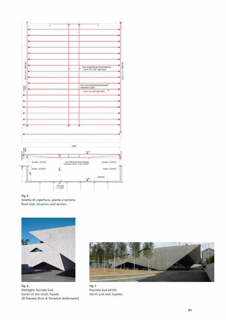
61
Fig. 5
Soletta di copertura, pianta e sezione.Roof slab: situation and section.
Fig. 7
Facciata Sud ed Est.North and east façades.
Fig. 6
Dettaglio facciata Sud.Detail of the south façade.(© Daniela Droz & Tonatiuh Ambrosetti)

62
del calcestruzzo durante il gettodella copertura e debitamenterinforzata alle estremità delletravi in modo da sostenere i cari-chi concentrati delle stesse dopola tesatura dei cavi di precompres-sione. La soletta di copertura èstata realizzata con un unicogetto così come le facciate peri-metrali (porzione fuori terra).Le strutture interrate, in partico-lare platea ed elevazioni dellapalestra, dei locali tecnici e deglispogliatoi sono state eseguite conil sistema della «vasca bianca»così da assicurarne l’impermeabi-lità.Particolare attenzione è stata infi-ne rivolta alle zone di appoggiodelle facciate Sud e Nord solleci-tate da sforzi assiali importanti ealla distribuzione di quest’ultiminelle pareti sottostanti, irrigiditelocalmente da contrafforti verti-cali. Agli appoggi la sollecitazione
concrete, without constructionjoints and visible recesses for theprestressing cables. During construction, the roof slabwas laid before the erection ofthe perimeter walls. The false-work of the roof slab has beenconstructed in order to supportthe distributed weight of the con-crete while pouring the roof andhas been suitably reinforced atthe edges of the prestressed beamsto support the concentratedweight after the installation ofthe prestressing cables. The roofslab has been casted in one singlestage, as has been done with theperimeter façades (the sectionsabove ground).The underground structures, inparticular the foundations andelevations of the gymnasium,equipment rooms and changingrooms, have been designed in linewith a “white-tank” system toensure waterproofing.Particular attention has been paidto the supporting areas of theSouth and North faces, which aresubjected to major axial forces,and to the distribution of suchforces into the underlying walls,locally reinforced by vertical struts.The axial pressure on the supportsreaches a force of ca. 11 MN andpresents a tilt of almost 22° (verti-cal force ca. 10 MN, horizontalforce ca. 4 MN).
assiale raggiunge uno sforzo dica. 11 MN e presenta un’inclina-zione di circa 22° (sforzo verticaleca. 10 MN, sforzo orizzontale ca.4 MN).
Hd = 4,0 MN
Vd =
10,
0 M
N
Fig. 8
Appoggio delle facciate Sud e Nord.Supports of the south and north façades.
Fig. 9
Dettaglio appoggio facciate.Detail of the façade support.
trazione/tension
compressione/
compression
Autori/Authors
Franco LuratiIng. dipl. ETHZ
Livio MuttoniIng. dipl. SUPSI
Mario PasseriniIng. dipl. SUPSI
Aurelio MuttoniProf. Dr ès techn., ing. dipl. ETHZ
Lurati Muttoni Partner SACH-6850 [email protected]
Committente/OwnerComune di MassagnoArchitetti/ArchitectsCDL Durisch Nolli Giraudi RadczuweitIngegnere civile/Civil engineerLurati Muttoni Partner SA
Realizzazione/Realisation2011–2017Costo dell’opera/Cost of the workca. 33 mio CHF (risanamento scuoleelementari e nuova palestra)ca. CHF 33 million (elementary schoolrenovation and new gymnasium)

63
EinleitungDie grösste Herausforderung derim Wettbewerb gestellten Auf ga -be bestand darin, einen Drei fach-Kindergarten und eine öffentlicheTiefgarage so anzuordnen, dassmöglichst viel Fläche für einenAussenraum freigehalten undden Kindern ein angemessenerGarten geboten werden kann.Dies liess sich nur erreichen,indem der Kindergarten auf derkompakten Grundfläche der ge -forderten Tiefgarage organisiertwurde.Den stark variierenden strukturel-len Anforderungen der beidenNutzungen (Kindergarten undTiefgarage) wurde mit dem Ent -scheid Rechnung getragen, überdem konventionellen Tiefgara gen -raster den Kindergarten als Hal len -tragwerk auszubilden. Vorge -spannte Ortbetonträger, die querüber die 18 m breite Garage span-nen, liegen auf den innerenFassadenscheiben des Kinder -gartens auf, die wiederum aufden Mauern der Tiefgarage ste-hen (Fig. 3, 4).
IntroductionThe biggest challenge of the com-petition brief consisted of arrang -ing a triple kindergarten and apublic underground garage in sucha way that the area for an out-door space could be maximizedwhich in turn would provide thechildren with a suitable garden.This could only be achieved byplacing the kindergarten over thecompact footprint of the proposedunderground garage.The vastly varying structuralrequirements for both services(kindergarten and undergroundgarage) were accommodated bythe decision to design the kinder-garten as a hall structure abovethe conventional undergroundgarage grid. Prestressed cast-in-place concrete beams that spanthe entire 18 m width of theunderground garage are set onthe inner load-bearing walls ofthe kindergarten (Fig. 3, 4).The shape and height of thebeams is dictated primarily by thehip roof, i.e. by the outer appea-rance of the kindergarten, which
Die Form und Höhe der Träger istin erster Linie durch das Walm -dach, also die äussere Erschei nungdes im Dorfkern von Würenlingensituierten Kindergartens bestimmt(Fig. 1). Im Innenraum akzentuie-ren die Träger die drei Kinder gar -tengruppen und erlauben durchgrosse, kreisförmige ÖffnungenBezüge zwischen diesen (Fig. 3b,7).Die sich zum Himmeldach entwi -ckelnde Betondecke ist zwischenden Trägern eingehängt und erin-nert an ein Zelt. Die Symbolik desZelts wird auf spielerische Art undWeise auf die Fassade übertra-gen, deren Oberfläche mithilfestandardisierter Matrizen als einvorhangartiges, textiles Relief inOrtbeton ausgebildet ist. Daraufberuht auch der bereits im Wett -bewerb verwendete Name «Zelt -haus» für das Projekt (Fig. 1a).
Konzept des TragwerksAllgemeinDas Tragkonzept des Dreifach-Kindergartens sieht offene, flexi-ble Räume ohne statisch aktivier-
Dreifach-Kindergarten mit öffentlicher Tiefgarage in WürenlingenTriple kindergarten featuring a public underground garagein Würenlingen
Christoph Reichen, Andrea Molinari
Fig. 1
a) Nahaufnahme des Kindergartens, b) Sicht auf den Gebäudekörper mit dem identitätsstiftenden Walmdach.a) Close-up of the kindergarten, b) view of the building with its characteristic hip roof.
(a) (b)

64
is located in the town centre ofWürenlingen (Fig. 1). Inside, thebeams, each with a large circularopening, accentuate the threekindergarten units and allowthem to relate to one another(Fig. 3b, 7).The skyroof-styled concrete slab ishinged between the beams andreminds one of a tent. The sym-bolism of the tent is playfully passed on to the facade which iscast as a curtain-like, textile reliefin cast-in-place concrete with thehelp of standardized molds. Hence,the name of the project, whichwas already used during the com-petition: “Tent House” (Fig. 1a).
te Innenwände vor (Fig. 2). Dieswird ermöglicht, indem eineBetondecke in vier trapezförmigeund zwei rechteckige, vorge-spannte Betonträger eingehängtwird, die auf der inneren, tragen-den Schicht einer zweischaligenAussenwand aus Beton lasten.Zugleich sind die vorgespanntenTräger in das räumliche Konzeptintegriert, indem sie als raum-trennende Elemente fungierenund die Kindergarteneinheitenvoneinander abgrenzen. Sämtliche Bestandteile der Trag -struktur der Tiefgarage sowie desdarüberliegenden Kindergartenssind in Ortbeton erstellt worden.
Structural concept GeneralThe structural concept of the tri-ple kindergarten stipulates open,flexible spaces without structural-ly activated interior walls (Fig. 2).This is rendered possible by fittinga con crete slab into four trape -zoidal and two rectangular, pre-stressed concrete beams whichrest on the inner, load-bearing wallof a double-leaf external con cretewall. At the same time, the pre-stressed beams are integrated intothe spatial concept by func tion ingas partitions and separat ing thethree kindergarten units fromone another.All elements of the structure of theunderground garage and the over -lying kindergarten were craftedwith cast-in-place concrete. Theload-bearing, monolithic concretestructure in the rooms of the kin-dergarten is left visible and theformwork pattern as well as theassociated shocks of the form-work panels are carefully plannedand coordinated. Inside, the visiblecon crete surfaces are complemen-ted with non-load bearing timberwalls and fixtures.
Execution and prestressig of thebeamsComplete prestressing of thebeams was necessary to preventthe creation of cracks and consi-derable deflection. Therefore,tensile stress inside the concretewas reduced to a minimum. Thetrapezoidal shape of the fourmiddle beams and the completeprestressing, however, required abeam width to be aligned withthe beam geometry as well as abending reinforcement from theupper to the lower edge of thebeam, located as required. An
Fig. 2
Innenraum im Rohbau mit reiner Tragstruktur.Interior in shell construction with load-bearing structure.
20 m
(a)
(b)
Fig. 3
a) Erdgeschossgrundriss, b) Längsschnitt.a) Ground floor plan, b) longitudinal section.
Bauherrschaft/OwnerGemeinde WürenlingenArchitekt/ArchitectMKCR Architekten, Zürich Ingenieur/EngineerCaprez Ingenieure, ZürichBauleitung/Site managementSchneider Spannagel Architekten AG,DöttingenUnternehmer/ContractorErne AG Bauunternehmung,Laufenburg

65
In den Kindergartenräumen wirddie tragende, monolithische Be -ton struktur sichtbar belassen, unddas Schalungsbild und die ent-sprechenden Stösse der Schal -tafeln sind sorgfältig geplant undkoordiniert. Die sichtbaren Beton -oberflächen werden im Innernmit nichttragenden Holzwändenund Einbauten ergänzt.
Ausführung und VorspannungTrägerUm einer Rissbildung und grösse-ren Durchbiegungen entgegen-zuwirken, wurde eine volle Vor -spannung der Träger notwendig.Zugspannungen im Beton wur-den somit auf ein Minimum redu-ziert. Die trapezförmige Form dervier mittleren Träger und die volleVorspannung bedingen jedocheine auf die Trägergeometrieabgestimmte Trägerbreite sowieeine sich je nach Lage verschie-bende Biegebewehrung vomoberen zum unteren Rand desTrägers. Auf eine Verbreiterungdes Trägers über die gesamteLänge wurde verzichtet, um denRaum zwischen den einzelnenTrägern so gross wie möglich zugestalten. Der komplexe, sich ver-ändernde Querschnitt des Trägers
increase in width of the beamalong the entire length was fore-gone, in order to maximise thespace between the individualbeams. The complex and chang -ing cross-section of the beam called for close collaboration withthe master builder both duringplanning and execution.The height of the two rectangularbeams at the edge is a mere 1.00 mand in the vicinity of the supportit narrows to 60 cm. The pre -stressing of the edge-beams waschosen such that the deflection ofall beams is within the samerange, in order to prevent loadredistribution caused by differen-tial deflection.With cables with up to 18 strands,the clamping chucks turned outaccordingly large which in turnled to reduced space at supportpoints. The high level of prestress -ing created compression stressaround the mounting area whichrequired concrete strength classC40/50. Since this is an exposedconcrete building, we decided tocomplete the entire roof with thesame concrete in order to reducepossible differences in colour bet-ween the roof slab and thebeams. There were ongoing tests
erforderte eine intensive Zusam -menarbeit mit dem Baumeister inder Planung und Ausführung.Die Höhe der zwei rechteckigenTräger an den Rändern liegt beinur gerade 1,00 m, die sich im Be -reich des Auflagers bis auf 60 cmverringert. Die Vorspannung derRandträger wurde so ausgelegt,dass sich die Durchbiegungenaller Träger im gleichen Bereichbewegen, um Lastumlagerungeninfolge differenzieller Durchbie -gun gen der Träger zu verhindern. Mit Kabeln aus bis zu 18 Litzenfielen die Spannköpfe gross ausund führten zu engen Platz ver -hältnissen in den Auflage punk ten.Durch den hohen Vorspannungs -grad entstanden in den Veran ke -rungsbereichen zudem Druck -spannungen, die einen Beton derFestigkeitsklasse C40/50 erforder-ten. Da es sich bei dem Objekt umeinen Sichtbetonbau handelt,wurde das gesamte Dach mitdemselben Beton ausgeführt, umallfällige Farbunterschiede zwi-schen Decke und Trägern zu redu-zieren. Damit die an den Betongestellten Anforderungen einge-halten und überprüft werdenkonnten, wurden laufend dieWürfeldruckfestigkeiten geprüft.
Fig. 4
Schnitt durch den Träger, der die nicht miteinander zu vereinendenStrukturen bzw. Raster von Tiefgarage und Kindergarten zusammenführt.Section of the beam that brings together structures or grids of the under-ground garage and the kindergarten that do not correspond.
Fig. 5
Innenraum des Kindergartens mitden in Leichtbau ausgeführten nicht-tragenden Holzständerwänden.Interior of the kindergarten withlightweight-design, non-loadbearingtimber stud partitions.

66
of the cube compression strengthto ensure that the requirementsof the concrete were met andtested. Additionally, the beamswere only prestressed after thehardening of the last roof slab, inorder to reduce stress redistribu -tion caused by subsequent loadson the beams.
FacadePlanningThe outer, structurally non-bear -ing exposed concrete wall with itswaved, textile surface representedquite a challenge during planningbecause we sought an efficientimplementation, from both aconstruction and an economicpoint of view. To reach a goodand pleasant outcome it was im -portant for the civil engineer, thearchitect and the master builderto collaborate closely and assisteach other throughout everyphase.The apparent continuous andvivid curtain-like relief is based ona basic module of 1.00 m, which isdivided into five segments whichvary in width. The irregularity ofthese widths enabled a standardi-zed mold module to react to thevarying lengths of the facade. Inaddition to the twelve 1.00 mlong standard molds, we manufac -tured individual mold segments
Zudem wurden die Träger erstnach dem Aushärten der letztenDecke vorgespannt, um Span -nungs umlagerungen infolge nach -träglicher Belastungen der Trägerzu vermindern.
FassadePlanungDie äussere, statisch nicht belaste-te Sichtbetonschale mit ihrer wel-lenförmigen, textilen Oberflächestellte bei der Planung eine grosseHerausforderung dar, da sowohlbaulich als auch wirtschaftlicheine effiziente Umsetzung ange-strebt wurde. Eine enge Zusam -men arbeit zwischen Bauingenieur,Architekt und Baumeister in sämt -lichen Phasen war wichtig für eingutes und erfreuliches Ergebnis. Das scheinbar durchgehende undlebendige, vorhangartige Reliefbasiert auf einem Grundmodulvon 1,00 m, das in fünf, in derBreite variierende Segmente un -ter teilt ist. Die Unregelmässigkeitder Segmentbreiten ermöglichtees, mit einem standardisiertenMatrizenmodul auf die unter-schiedlichen Längen der Fassadenzu reagieren. Zu den zwölf 1 mlangen Standardmatrizen wurdenaus der gleichen Schalung derStandardmatrizen zusätzlich ein-zelne Matrizensegmente erstellt,die jeweils an den Etappenenden
from the same formwork, whichwere put together at the finalstage according to the remaininglength (Fig. 8).To be able to guarantee as precisea transition as possible betweenthe pedestal and the waved fa -cade, the two elements were casttogether in the same stage. Tothis end, the molds were merelyput on a conventional formworkpanel (Fig. 9). An overhang onthe pedestal protrudes from therear-thickness of the mold, a rem-nant from the construction pro-cess. The conscious use of twoformwork elements, mold andformwork panel, and their diffe-rence in surface texture aremeant to evoke a rupture, despitebeing constructed at the sametime, and illustrate the artisticelement of the pedestal.Due to the dimensions of thefacade it has to withstand tempe-rature expansions of up to 10 mm,which was scrutinized more close-ly using the tension chord model.The basis for the calculations is ashrinkage-proof wall where thehorizontally required reinforce-ment is purposely weakened atselect places in order to cause theformation of cracks at thosespots. Dilatation joints in the cor-ners reduce the tension in theconcrete.
Fig. 6
Bewehrung Träger.Reinforcement of the beam.
Fig. 7
Zwei Träger bilden jeweils eine Spielnische zwischen zwei Kindergarten -abteilungen und erlauben mit ihren Öffnungen Blickbezüge zwischen diesen.Two beams create a play niche between the kindergarten units, allowing fora visual reference between them through the openings.

67
entsprechend den Restlängen zu -sammengesetzt wurden (Fig. 8).Um einen möglichst präzisen Über -gang zwischen Sockel und ge -wellter Fassade gewährleisten zukönnen, wurden die beiden Bau -teile miteinander vergossen. Dazuwurden die Matrizen lediglich aufeine konventionelle Schaltafel auf -gebracht (Fig. 9). Aus der Rücken -stärke der Matrize ergibt sich einÜberstand des gebauten Sockels,der als Artefakt aus dem Bau pro -zess erhalten bleibt. Die bewussteVerwendung zweier Schalungs -ele mente, Matrize und Schal talfel,soll trotz der baulichen Gleich zei -tigkeit mit ihren unterschiedli-chen Oberflächen einen Bruchbewirken und so das gestalteri-sche Element des Sockels veran-schaulichen.Aufgrund ihrer Dimension mussdie Fas sade mit Temperatur aus -deh nungen von bis zu 10 mm um -gehen können, was anhand desZuggurtmodells genauer unter-sucht wurde. Grundlage für dieBerechnung stellte eine schwind-behinderte Wand dar, wobei diehorizontal erforderliche Beweh -rung an bestimmten Orten be -wusst geschwächt wurde, um dieRissbildung an diesen Orten her-vorzurufen. Dilatationsfugen inden Ecken verringern die Span -nun gen im Beton.
ExecutionThe stringent requirements forthe exposed concrete (exposedconcrete class 3) and the compli-cated, elaborate shape of thefacade elements lead to the reso-lution to first create the non-bear ing facade before the load-bearing, inner wall of the double-leaf construction. This allowed forthe double-faced formwork forthe outer skin, in a way that thereinforcement as well as thedistance brackets for the reinfor-cement cover were not shiftedand the sought after quality ofthe visible surfaces was achieved.Subsequently, the interior wallwith its glossy surface was con -creted with a single-sided form-work to the facade.All binding holes were filled afterthe fact with a mortar whosecolour was calibrated with thecolour of the concrete such that,for example, an allocation of theformwork binders could be dis-pensed with.
AusführungDie hohen Anforderungen an denSichtbeton (Sichtbetonklasse 3)und die komplizierte, kunstvolleForm der Fassadenelemente führ-ten zu dem Entschluss, die nicht-tragende Fassade vor der tragen-den, inneren Schicht der zwei-schaligen Konstruktion zu erstel-len. Dies ermöglichte ein doppel-häuptiges Schalen der äusserenHaut, sodass die Bewehrungsowie die Abstandshalter für dieBewehrungsüberdeckung nichtverschoben wurden und sich dieangestrebte Qualität der sichtbarbleibenden Oberflächen errei-chen liess. Danach wurde dieInnenwand mit ihrer glattenOberfläche einhäuptig an dieFassade betoniert.Sämtliche Bindelöcher wurden imNachhinein mit einem farblichauf den Beton abgestimmtenMörtel verfüllt, sodass auf eineEinteilung der Schalungsbinderverzichtet werden konnte.
1
121cm
219cm
322cm
420cm
518cm
121cm
219cm
322cm
420cm
518cm
322cm
420cm
121cm
219cm
322cm
322cm
219cm
ion 0. 0. 100. 100
Ortbeton Matrize
Fig. 8
Ausschnitt Matrizenplan mit einerAusnahme am Etappenende.Section of mold plan with oneexception at the end of a stage.
Fig. 9
Axonometrie der Standartmatrize auf Schaltafel mitÜberstand für den Sockelanschluss.Axonometric section showing standard mold on form-work panel with overhang for connection to pedestal.
Autoren/Authors
Christoph ReichenMSc ETH Architekt MKCR ArchitektenCH-8045 Zü[email protected]
Andrea MolinariBSc Bauing. FHOCaprez Ingenieure AGCH-8036 Zü[email protected]