ho me magnetic cycle - proteus · pdf filepec-1900 series home magnetic cycle assembly...
TRANSCRIPT

Owner's manual
-PEC 1900 SERIES
MAGNETIC CYCLE
ME HO

PEC-1900 SERIES HOME MAGNETIC CYCLE ASSEMBLY INSTRUCTION
Important safety precautions
1. Read the owner's manual and all accompanying literature and follow it carefully before using your machine.
2. This machine is intended for household use only. It is not designed for commercial use.
3. Inspect your exercise machine prior to exercising to ensure that all nuts and bolts are fully tightened before each use.
4. Make sure machine is stabilized on the floor and uneven surfaces are leveled before use.
5. Most exercise equipment is not recommended for small children. Children should not use the machine unless they are under adult supervision.
6. Exercise equipment has moving parts. In the interest of safety, keep others, especially children, at a safe distance while exercising.
7. Make sure all adjustment devices are fully inserted and properly adjusted before use to avoid injury.
8. Remove all jewelry, including rings, chains and pins before commencing exercise.
9. Always wear suitable clothing and footwear during exercise. Do not wear loose fitting clothing that could become entangled with the moving parts of your exercise machine.
10. Warm up 5 to 10 minutes before each workout and cool down 5 to 10 minutes afterward. This allows your heart rate to gradually increase and decrease and will help prevent straining muscles.
11. Never hold your breath while exercising. Breathing should remain at a normal rate in conjunction with the level of exercise being performed.
12. Rest adequately between workouts. Muscles tone and develop during these rest periods. Beginners should work out twice a week and increase gradually to 4 or 5 times per week.
13. Do not "over train". Incorrect or excessive training may result in injury.
- 1 -NOTE : THE EQUIPMENT IS SPEED-DEPENDENT ON BRAKING SYSTEM.
IMPORTANT : THE MAXIMUM RECOMMENDED WEIGHT CAPACITY FOR YOUR EQUIPMENT IS 110 KG ( 240 LB ) PER USER.
- 1 -
THIS OWNER'S MANUAL CONTAINS ASSEMBLY, OPERATION, MAINTENANCE AND SAFETY INFORMATION. IN THE INTEREST OF SAFETY, PLEASE MAKE CERTAIN THAT YOU READ AND UNDERSTAND ALL THE INFORMATION BELOW.
Warning : Before commencing with any exercise program, please consult your family physician. If at any time during exercise you feel faint, dizzy or experience pain, stop and consult your family physician. In the event any of the above mentioned warnings are breached by the consumer, the manufacturer may use same as a defense to any claim for injuries, damage or loss. The above warnings are in no way intended to limit or modify the consumer's remedies for breach of warranties pursuant to applicable federal and state laws of regulations. They are being supplied strictly to ensure the safety of the individuals using this product.
The appliances are not for children under 14 years of ages.
Before you begin
Important : Read all instructions carefully. Assemble the unit in accordance with the steps in the manual. Lay out all parts on the floor and check if you have all the parts included completely before beginning assembly. In case of a discrepancy, please call the customer service department of the store for help.
Note : Some parts may be factory pre-assembled.
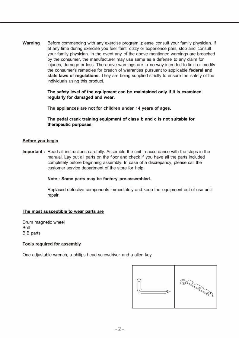
Tools required for assembly
One adjustable wrench, a philips head screwdriver and a allen key
The safety level of the equipment can be maintained only if it is examined regularly for damaged and wear.
The pedal crank training equipment of class b and c is not suitable for therapeutic purposes.
Replaced defective components immediately and keep the equipment out of use until repair.
The most susceptible to wear parts are
Drum magnetic wheelBeltB.B parts
- 2 -

- 3 -
MAGNETIC CYCLE ASSEMBLY INSTRUCTION
IMPORTANT : READ ALL STEPS BEFORE ATTACHING PEDALS
Step 1. Attach both front and rear stabilizers ( 2/3 ) to main frame ( 01 ), fix with carriage bolts ( 27 ) washers ( 30 ) and dome nuts ( 34 ).
Step 2.
a. Attach pedals ( 18 / 19 ) to pedal cranks, ( pedals marked "L" and "R" indicates left and right side of bike. Make sure not to mix it up ).
b. Left pedal has left hand thread and must be turned counter- clockwise ( ccw ) to attach, right pedal has right hand thread, must be turned clockwise ( cw ) to attach.
Step 3. Attach saddle ( 13 ) to saddle plate of seat post ( 04 ) fasten with spring washers ( 32 ) and nylon nuts ( 33 ).
Step 4. Attach seat post ( 04 ) to seat post support ( on main frame ), adjust saddle to desired height and tighten with knob ( 14 ).
Step 5. Insert tension cable ( 10 ) inside of handle bar post ( 05 ), pull the tension cable out from middle hole of handle bar post. Connect wire A ( 11 ) and wire B ( 12 ), then attach handlebar post to main frame ( 01 ), fix with bolts ( 28 ) and washers ( 30 ). Assemble tension control knob ( 09 ) and tension cable ( 10 ), by connecting cable head ( on knob ) to the draw hook of tension cable ( please refer to FIG. A & FIG. B ). Assemble the tension control knob ( 09 ) onto handlebar post ( 05 ). Note the fix-hook (on tension control ) well inserted onto handle bar post. Then tighten with screw ( 26 ).
Assemble handlebar & monitor( 1 ) If your model no. is PEC-1900/1900EP/1905/1905EP/1925HP, please do step 6. &
step 7.( 1 ) If your model no. is PEC-1900GP/1905GP/1935GP. please do step 8.
Step 6. Assemble foam grip ( 17 ) and end cap ( 16 ) onto one side of handlebar ( 06 ), then attach handlebar ( 06 ) to handle bar post ( 05 ), tighten with washer ( 31 ) and T-knob( 25 ). Assemble foam grip ( 17 ) and end cap ( 16 ) onto another side of handlebar ( 06 ).Note : Use some soap water as lubricant while fitting foam grips.
Step 7. Assemble wire A ( 11 ) to monitor ( 08 ), then attach monitor on fixplate of handlebar post.

MAGNETIC CYCLE ASSEMBLY INSTRUCTION
Step 8. a. Attach half moon bracket ( 38 ), handlebar ( 06 ) to handlebar post ( 05 ) and fix with screw ( 37 ), T-knob ( 25 ) & washer ( 31 ). Do not overtighten the screw & T-knob before the handlebar located in desired position. ( Please refers to FIG. C )
( Note To adjust angle of handlebar, by unscrewing T-knob then tighten it firmly. )
b. Insert the grip pulse wire ( 35 ) into the handlebar post and let it through the top of monitor mounting plate.
c. Connecting wire A ( 11 ) & grip pulse wire ( 35 ) with monitor ( 08 ). ( Please refers to FIG. D )
d. Slide the monitor into mounting plate carefully.
**** Now your PEC-1900 series has been well assembled. ****
" THE BATTERIES MUST BE REMOVED FROM THE APPLIANCE BEFORE IT IS SCRAPPED AND THAT THEY ARE DISPOSED OF SAFELY ".
- 4 -

- 5 -
EXPLODED VIEW
10
9
10
16
17
30
27
1
21
30
34
7
22
14
19
15
4
28
33
3210
13
26
11 FIG. A
24
18
27
30
23
2
34
28
20
30
12
FIG. B
2531
5
9
6
11
8
3
9
11
PEC-1935
6
36
8
39
35
6
11
8
39
35
36
525
3831
6
37
KEYALLEN
35
PEC-1905 FIG.D PEC-1905/1935 FIG.C
PEC-1900
PEC-1925
6
11
8

- 6 -
PARTS LIST
K
1. 1 Main frame
2. 1 Front stabilizer
3. 1 Rear stabilizer
4. 1 Seat post
5. 1 Handlebar post
6. 1 Handlebar
7. 1 Crank assembly
8. 1 Cyclemonitor
9. 1 Tension control
10. 1 Tension cable
11. 1 Wire ( A )
12. 1 Wire ( B )
13. 1 Saddle
14. 1 Knob
15. 1 60 sleeve
16. 2 Handlebar end cap
17. 2 Foam grip
18. 1 Pedal ( R )
19. 1 Pedal ( L )
20. 1 Chain cover ( R )
21. 1 Chain cover ( L )
22. 2 Crank hole cover
23. 2 Foot cap ( A )
24. 2 Foot cap ( B )
25. 1 T-knob
26. 1 M4 screw x 15mm
27. 4 M8 carrage bolt x 70mm
28. 3 M8 socket bolt x 15mm
30. 7 M8 washer
31. 1 M8 small washer
32. 3 M8 spring washer
33. 3 M8 nylon nut
34. 4 M8 dome nut
35. 1 Grip pulse wire
36. 2 Grip pulse
37. 1 M7 socket screw x 20mm
38. 1 Half-moon bracket
39. 2 M5 screw x 25mm
ey Q'ty Description

GB
PEC1900SERIES-050221GB