hnf-spec-61935 - hanford.gov_rev._0,_l... · astm c143 standard test method for slump of...
TRANSCRIPT

HNF-SPEC-61935Revision 0
TRADEMARK DISCLAIMERReference herein to any specific commercial product, process, or service bytradename, trademark, manufacturer, or otherwise, does not necessarilyconstitute or imply its endorsement, recommendation, or favoring by theUnited States Government or any agency thereof or its contractors orsubcontractors.
This report has been reproduced from the best available copy.
Printed in the United States of America
L-894-C1
Raw Water Cross-Connection Isolation Project
MISSION SUPPORT ALLIANCE
Page 2 3/9/2018 HNF-SPEC-61935
TABLE OF
CONTENTS
Title Page
Table of Contents
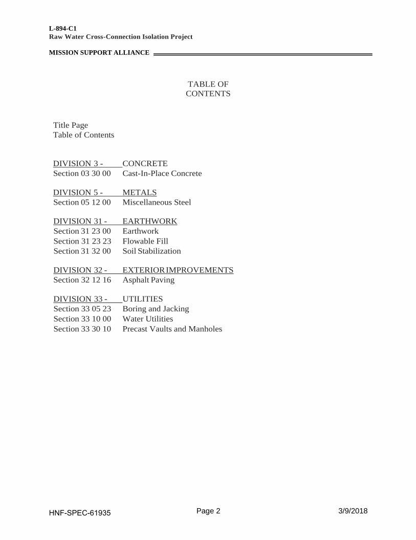
DIVISION 3 - CONCRETE
Section 03 30 00 Cast-In-Place Concrete
DIVISION 5 - METALS
Section 05 12 00 Miscellaneous Steel
DIVISION 31 - EARTHWORK
Section 31 23 00 Earthwork
Section 31 23 23 Flowable Fill
Section 31 32 00 Soil Stabilization
DIVISION 32 - EXTERIOR IMPROVEMENTS
Section 32 12 16 Asphalt Paving
DIVISION 33 - UTILITIES
Section 33 05 23 Boring and Jacking
Section 33 10 00 Water Utilities
Section 33 30 10 Precast Vaults and Manholes
HNF-SPEC-61935 Section 03 30 00
Raw Water Cross-Connection Isolation Project Page 1 of 6
MISSION SUPPORT ALLIANCE
HNF-SPEC-61935 03 30 00, Rev. 0 3/9/2018
Section 03 30 00
CAST-IN-PLACE CONCRETE
PART 1 – GENERAL
1.1 SCOPE
This specification covers materials and installation of concrete for thrust blocks and other
incidental uses of concrete.
1.2 REFERENCES
The following documents and others referenced therein form part of the Contract to the extent
designated in this Section. Referenced documents are those current as of the date of this Section
unless otherwise indicated.
1.2.1 American Concrete Institute (ACI)
ACI 117 Tolerances for Concrete Construction and Materials
ACI 301 Specifications for Structural Concrete
1.2.2 ASTM International (ASTM)
ASTM A615 Standard Specification for Deformed and Plain Carbon-Steel Bars
for Concrete Reinforcement
ASTM A853 Standard Specification for Steel Wire, Carbon, for General Use
ASTM A1064 Standard Specification for Carbon-Steel Wire and Welded Wire
Reinforcement, Plain and Deformed, for Concrete
ASTM C31 Standard Practice for Making and Curing Concrete Test Specimens
in the Field
ASTM C33 Standard Specification for Concrete Aggregates
ASTM C39 Standard Test Method for Compressive Strength of Cylindrical
Concrete Specimens
ASTM C94 Standard Specification for Ready-Mixed Concrete
ASTM C143 Standard Test Method for Slump of Hydraulic-Cement Concrete
ASTM C150 Standard Specification for Portland Cement
ASTM C173 Standard Test Method for Air Content of Freshly Mixed Concrete
by the Volumetric Method
ASTM C260 Standard Specification for Air-Entraining Admixtures for Concrete
HNF-SPEC-61935 Section 03 30 00
Raw Water Cross-Connection Isolation Project Page 2 of 6
MISSION SUPPORT ALLIANCE
HNF-SPEC-61935 03 30 00, Rev. 0 3/9/2018
ASTM C1107 Standard Specification for Packaged Dry, Hydraulic-Cement Grout
(Nonshrink)
ASTM D994 Standard Specification for Preformed Expansion Joint Filler for
Concrete (Bituminous Type)
1.3 SUBMITTALS
1.3.1 See Statement of Work (SOW) for submittal procedure.
1.3.2 For Approval
1.3.2.1 Concrete mix design
1.3.3 Not For Approval
1.3.3.1 Trip Tickets
1.3.3.2 Test Results
- Air Entrainment
- Slump
- Compressive Strength
1.4 QUALITY ASSURANCE
1.4.1 Subcontractor’s Quality Control System: See Statement of Work (SOW).
1.4.2 Deliverable Documentation: The following documents and records, required by this
Section, shall be delivered to the Buyer in accordance with the SOW.
Document Paragraph
Concrete Test Results 3.4
1.5 DELIVERY, STORAGE, AND HANDLING
1.5.1 See SOW for General Requirements
PART 2 – PRODUCTS
2.1 SUBSTITUTES
2.1.1 See the Subcontract SOW for substitution approvals.

HNF-SPEC-61935 Section 03 30 00
Raw Water Cross-Connection Isolation Project Page 3 of 6
MISSION SUPPORT ALLIANCE
HNF-SPEC-61935 03 30 00, Rev. 0 3/9/2018
2.2 MATERIALS
2.2.1 Concrete
2.2.1.1 Cement: ASTM C150, Type II (low alkali).
2.2.1.2 Aggregates: ASTM C33, 1 inch maximum size
2.2.1.3 Air-Entraining Admixture: ASTM C260; Sika Chemical Company “SIKA AER,”
Chem-Masters Corporation “Adz-Air,” or Protex Industries “AES.”
2.2.1.4 Properties:
a. Minimum allowable compressive strength: 3,000 lb/in2 at 28 days.
b. Slump: 4 inches maximum without admixtures, 8 inches maximum with
admixtures in accordance with ACI 301, Section 4.2.2.2.
c. Air Content: In accordance with ACI 301, Section 4.2.2.4.
d. Proportions: In accordance with ACI 301, Section, 4.2.3 and ASTM C94.
2.2.2 Approved Mix Designs:
a. American Rock, INC – Mix Design #150124 (3000 psi), #51550A (4000 psi), or
59600F (5000 psi) or approved equal.
2.2.3 Measuring, Mixing, and Delivery: In accordance with ASTM C94.
2.2.4 Reinforcing Steel
2.2.4.1 Steel bars: ASTM A615, smooth or deformed, Grade 60.
2.2.4.2 Welded wire fabric: ASTM A1064.
2.2.4.3 Tie wire: ASTM A853 carbon steel, 16-gage minimum, annealed.
2.2.5 Joint Materials
2.2.5.1 Expansion joint filler: ASTM D994, Watson Bowman and Acme Corporation “W”
Series.
2.2.6 Nonshrink Grout: Nonmetallic type ASTM C1107; Sika Corporation “Sika Grout
212,” BASF Master Builders, “MasterFlow 713,” U.S. Grout Corporation “Five Star
Grout,” or Hallemite “Por-Rok” anchoring cement.
2.2.7 Forms: Work, steel, plywood, or Masonite Corporation “Concrete Form Presdwood,”
as required for various specified finishes.
HNF-SPEC-61935 Section 03 30 00
Raw Water Cross-Connection Isolation Project Page 4 of 6
MISSION SUPPORT ALLIANCE
HNF-SPEC-61935 03 30 00, Rev. 0 3/9/2018
2.2.8 Form Coating Materials: Symons Corporation ”Magic Kote,” AC Horn Incorporated
“Form Shield,” or Burke Company “Burke Release No. 1.”
PART 3 – EXECUTION
3.1 GENERAL
3.1.1 Concrete construction shall follow the requirements specified in ACI 301 in its entirety,
as applicable to design conditions and requirement.
3.1.2 Wall Repair: Chip out and remove concrete as shown on Drawings. Cold Bend
reinforcing steel as required to permit installation of pipe and pipe sleeves. Provide
shoring and supports of piping until concrete has had sufficient time to cure and the
trench is backfilled. See 3.1.1 for concrete requirements.
3.2 PREPARATION
3.2.1 Formwork Construction
3.2.1.1 Install formwork in accordance with ACI 301, Section 2. Interior shape and rigidity
shall be such that finished concrete will meet requirements of the Drawings within
tolerances specified in ACI 117, Section 2.2.
3.2.1.2 Forms for surfaces which will be permanently concealed from view may be saturated
with water (instead of other treatment) before placing concrete. In freezing weather,
forms shall be treated with oil or stearate.
3.2.1.3 Clean forms of foreign material before placing concrete.
3.3 INSTALLATION
3.3.1 Reinforcing Steel
3.3.1.1 Fabricate bars to within tolerances shown in ACI 301, Section 3.
3.3.1.2 Place within tolerances specified in ACI 117, Section 2.2.
3.3.1.3 Tie to prevent displacement during placement of concrete.
3.3.1.4 Do not force rebar into concrete after initial set has started.
3.3.1.5 Install reinforcing steel of like size at wall penetration in the event reinforcing steel is
broken, or as directed by the Buyer.
HNF-SPEC-61935 Section 03 30 00
Raw Water Cross-Connection Isolation Project Page 5 of 6
MISSION SUPPORT ALLIANCE
HNF-SPEC-61935 03 30 00, Rev. 0 3/9/2018
3.3.2 Concrete
3.3.2.1 Before placing:
a. Approve “Pour Slip,” including identification of sections of structure to be placed,
maximum size of coarse aggregate, and design strength.
b. For each truck load, collect “Trip Ticket.” “Trip Tickets” shall contain information
listed in ASTM C94, paragraphs 14.1.1 through 14.1.10, and water/cement ratio.
c. Identify location to discharge concrete rinsate with Buyer approval. See SOW.
3.3.2.2 Place in accordance with ACI 301, Section 5. Do not drop more than 5 feet. Insert
vibrator, vertically if possible, into concrete and reach small distance into concrete in
next lower layer. Do not insert vibrators into lower courses that have reached initial
set. Avoid contact between vibrator head and forms, reinforcement, or embedded
items.
3.3.2.3 Allow concrete a minimum of 7 days of cure time prior to loading, unless concrete
strength testing proves that concrete has met 70% of 28-day strength. High early
strength or higher strength concrete may be substituted to accelerate schedule.
3.3.2.4 Place non-shrink grout where required, in accordance with manufacturer’s
recommendations.
3.3.2.5 Weather conditions: Refer to ACI 301, Section 4.2.2.5 for limits on hot and cold
weather concrete placement. Protect placed concrete in accordance with ACI 301
Sections 4 and 5.
3.3.2.6 Construction joints: Make in accordance with ACI 301, Section 5.3.2.6 and details on
the Drawings.
3.3.2.7 Placing concrete against earth: Place on or against firm, damp surfaces free of frost, ice
and free water. Before concrete placement, obtain required earth compaction in
accordance with Section 31 23 00 – Earthwork. Dampen earth surfaces that are to
receive fresh concrete.
3.3.3 Form Removal and Concrete Repair
3.3.3.1 Form removal: Remove in accordance with ACI 301, Section 2.3.2.
3.3.3.2 Concrete Repair: Per ACI 301, Section 5.3.7 or as directed by the Buyer.
3.3.4 Concrete Finishes and Tolerances
3.3.4.1 Unformed surfaces: Broom finish in accordance with ACI 301, Section 5.3.4 for
exterior slabs subject to foot traffic.

HNF-SPEC-61935 Section 03 30 00
Raw Water Cross-Connection Isolation Project Page 6 of 6
MISSION SUPPORT ALLIANCE
HNF-SPEC-61935 03 30 00, Rev. 0 3/9/2018
3.4 CONCRETE TESTING
3.4.1 Prior to placement, test fresh concrete for air entrainment in accordance with ASTM
C173 and slump in accordance with ASTM C143.
3.4.2 For strength testing, prepare concrete test cylinders during concrete placement, field
cure cylinders, and break cylinders at a certified lab prior to loading. Test samples
require two test cylinders for each strength test performed, using the average value for
concrete strength. Mold cylinders in accordance with ASTM C31 and test in
accordance with ASTM C39. Document test results and demonstrate that required
strength has been achieved.
3.4.3 Concrete strength testing is only required if the concrete will be loaded prior to
reaching a 7 day cure time.
3.5 PROTECTION
3.5.1 Protect concrete during extreme weather conditions and from mechanical damage in
accordance with ACI 301, Section 5.
HNF-SPEC-61935 Section 05 12 10
Raw Water Cross-Connection Isolation Project Page 1 of 4
MISSION SUPPORT ALLIANCE
HNF-SPEC-61935 05 12 10, Rev. 0 3/9/2018
Section 05 12 10
MISCELLANEOUS STEEL
PART 1 – GENERAL
1.1 SCOPE
This specification covers material and installation of steel for weir modifications and pipe supports.
1.2 REFERENCES
The following documents and others referenced therein form part of the Contract to the extent
designated in this Section. Referenced documents are those current as of the date of this Section
unless otherwise indicated.
1.2.1 American Institute of Steel Construction (AISC)
AISC ASD Steel Construction Manual, Allowable Stress Design, 14th Edition
1.2.2 American Society of Mechanical Engineers (ASME).
B18.21.1 Lock Washers (Inch Series)
1.2.3 ASTM International (ASTM)
ASTM A36 Standard Specification for Carbon Structural Steel
ASTM A53 Standard Specification for Pipe, Steel, Black and Hot-Dipped, Zinc-
Coated, Welded and Seamless
ASTM A108 Standard Specification for Steel Bar, Carbon and Alloy, Cold-
Finished
ASTM A240 Standard Specification for Chromium and Chromium-Nickel
Stainless Steel Plate, Sheet, and Strip for Pressure Vessels and for
General Applications
ASTM A307 Standard Specification for Carbon Steel Bolts, Studs, and Threaded
Rod 60,000 PSI Tensile Strength
ASTM A563 Standard Specification for Carbon and Alloy Steel Nuts
ASTM F593 Standard Specification for Stainless Steel Bolts, Hex Cap Screws,
and Studs
1.2.3 American Welding Society (AWS)
AWS D1.1 Structural Welding Code – Steel
AWS D1.6 Structural Welding Code – Stainless Steel
HNF-SPEC-61935 Section 05 12 10
Raw Water Cross-Connection Isolation Project Page 2 of 4
MISSION SUPPORT ALLIANCE
HNF-SPEC-61935 05 12 10, Rev. 0 3/9/2018
1.3 SUBMITTALS
1.3.1 See Statement of Work (SOW) for Submittal Procedure.
1.3.2 Approval Not Required
1.3.2.1 Welding Personnel and Inspection Personnel Certifications and/or Qualifications
1.3.2.2 Welding, weld examination, and weld testing procedures
1.3.2.3 Weld Examination Results
1.4 QUALITY ASSURANCE
1.4.1 Subontractor's Quality Assurance Program: See SOW.
1.4.2 Welding shall be in accordance with AWS D1.1 and AWS D1.6. Welders shall possess
current qualifications for the intended welding in accordance with AWS D1.1 and AWS
D1.6. Welding inspectors shall possess current certification as an AWS Certified
Welding Inspector in conformance with the provisions of AWS QCI, Standard for AWS
Certification of Welding Inspectors. Prior to welding, submit qualifications of welders
and welding inspectors, planned welding procedures and welding inspection and testing
procedures.
1.4.3 Deliverable Documentation: The following documents and records, required by this
Section, shall be delivered to the Buyer in accordance with the SOW.
Document Paragraph
Weld Examination Results 3.4.1
1.5 DELIVERY, STORAGE, AND HANDLING
1.5.1 See SOW for general requirements.
PART 2 – PRODUCTS
2.1 SUBSTITUTES
2.1.1 See Subcontractor SOW for substitution approvals.
2.2 MATERIALS
2.2.1 Rolled Steel Shapes and Plates: ASTM A36.
HNF-SPEC-61935 Section 05 12 10
Raw Water Cross-Connection Isolation Project Page 3 of 4
MISSION SUPPORT ALLIANCE
HNF-SPEC-61935 05 12 10, Rev. 0 3/9/2018
2.2.2 Steel Bars and Rods: ASTM A108, minimum yield 36,000 lb/in2, maximum carbon
content 0.35%.
2.2.3 Steel Pipe: ASTM A53, Type E or S, Grade B.
2.2.4 Stainless Steel Shapes and Plates: 304 Stainless Steel in accordance with ASTM A240.
2.2.5 Fasteners
2.2.4.1 Fasteners shall have a Class 2 fit.
2.2.4.2 Bolts and Threaded Tie-Rods: ASTM A307, Grade A or B.
2.2.4.3 Nuts: ASTM A563, Grade A, heavy hex.
2.2.4.4 Washers: ASME B18.21.1.
2.2.4.5 Expansion anchors: Hilti Kwik Bolt TZ or an approved substitute.
2.2.4.6 Welding Electrodes: E7018; 308L.
2.2.4.7 Stainless Fasteners: ASTM F593
2.2.5 Non-Shrink Grout: See Section 03 30 00.
PART 3 – EXECUTION
3.1 FABRICATION
3.1.2 General
3.1.2.1 Verify measurements and take field measurements necessary before fabrication. Provide
miscellaneous bolts and anchors, supports, braces, and connection necessary for
completion of metal fabrications. Weld connections as shown on the Drawings.
3.1.2.2 Workmanship: Form metal fabrications to shape and size, with sharp lines, angles, and
true curves.
3.1.2.3 Jointing and intersections: Accurately made, tightly fitted, and in true planes with
adequate fastenings.
3.1.2.4 Perform welding of steel connections in accordance with AWS D1.1.
3.1.3 Finishes
HNF-SPEC-61935 Section 05 12 10
Raw Water Cross-Connection Isolation Project Page 4 of 4
MISSION SUPPORT ALLIANCE
HNF-SPEC-61935 05 12 10, Rev. 0 3/9/2018
3.1.3.1 Ferrous metal shall be hot-dip galvanized.
3.1.3.2 Touch up damaged zinc surfaces with zinc-rich coating. Apply in accordance with
manufacturer’s instructions.
3.2 ERECTION
3.2.1 Erect structural steel in accordance with AISC 335 SUPP 1, except welding shall be in
accordance with this Section.
3.2.2 Perform welding in accordance with AWS D1.1 and AWS D1.6.
3.2.3 Fabricate welded connections in accordance with AISC ASD, Table IV, Part 4.
3.2.4 Square the ends of pipe supports at base plates.
3.2.5 Do not make holes in framing members for supporting equipment, unless shown on the
Drawings, without approval from the Buyer. 3.2.6 Use ASTM A307 bolts with lock washers under nuts. Tighten nuts with hand
wrenches to compress lock washers.
3.2.7 Expansion Anchors:
3.2.7.1 Install expansion anchors in accordance with manufacturer’s instructions where shown on
the drawings.
3.2.7.2 Prior to installing expansion anchors, perform a concrete scan to identify embedded steel
reinforcement, electrical conductors, etc.
3.3 APPLICATION
3.3.1 Paint
3.3.2 Touchup: After erected steel has been approved, clean and paint connections with primer
and finish coat. Touchup shop prime coat where damaged. Prime and touchup with shop
coat primer and finish coat. To maximum extent practicable, perform placement
continuously.
3.4 FIELD QUALITY CONTROL
3.4.1 Weld Examination: Perform visual examination in accordance with AWS D1.1,
paragraphs 6.5 and 8.6 and AWS D1.6, paragraph 8.5. Record results.
HNF-SPEC-61935 Section 31 23 00
Raw Water Cross-Connection Isolation Project Page 1 of 8
MISSION SUPPORT ALLIANCE
HNF-SPEC-61935 31 23 00, Rev. 0 3/9/2018
Section 31 23 00
EARTHWORK
PART 1 – GENERAL
1.1 SCOPE
This specification covers earthwork, including excavation, pipe bedding, backfilling, and soil
compaction for demolition of existing water system components and installation of new water
lines.
1.2 REFERENCES
The following documents and others referenced therein form part of the Contract to the extent
designated in this Section. Referenced documents are those current as of the date of this Section
unless otherwise indicated.
1.2.1 ASTM International (ASTM)
ASTM D653 Standard Terminology Relating to Soil, Rock, and Contained
Fluids
1.2.2 Code of Federal Regulations (CFR) Title 29, Labor
Part 1926 Safety and Health Regulations for Construction
1.2.3 Department of Energy
DOE-0344 Hanford Site Excavating, Trenching and Shoring Procedure
(HSETSP), Revision 3A
1.2.4 Occupational Safety and Health Administration (OSHA)
OSHA Regulations Code of Federal Regulations 29 CFR 1926.650-1926.652, Subpart
P-Excavation, latest revision.
1.2.5 Washington State Department of Transportation (WSDOT)
M 41-10 Standard Specifications for Road, Bridge, and Municipal
Construction
M 46-01 Materials Branch Laboratory Manual
1.3 SUBMITTALS
1.3.1 See Statement of Work (SOW) for submittal procedures.
HNF-SPEC-61935 Section 31 23 00
Raw Water Cross-Connection Isolation Project Page 2 of 8
MISSION SUPPORT ALLIANCE
HNF-SPEC-61935 31 23 00, Rev. 0 3/9/2018
1.3.2 Approval Required
1.3.2.1 Damage prevention procedure: Notify the Buyer before excavation, submit procedure
to prevent overstressing existing structures, and interrupting existing services.
1.3.2.2 Location of existing utilities: Notify the Buyer prior to exploratory excavations (Pot-
holing) to identify the location of existing utility lines which could be affected by the
planned excavations. Existing crossing and adjacent utilities are shown on the
drawings and scan data.
1.3.2.3 Shoring Plan: See Section 3.1.6.
1.3.2.4 As-built survey data: Submit electronic data file on thumb drive or CD for as-built
profile of buried pipe and prepared subgrade required in 3.2.4.
1.3.2.5 Traffic Control Plan: See Section 32 12 16 – 1.3.2.2.
1.3.2.6 Competent Person: Before excavation and in writing, submit the identity of individual
designated as the Earthwork Inspector. The individual shall be the Competent Person
as defined in OSHA Regulations 29 CFR 1926.650, DOE-0344, and required by IS&H
Manual.
1.3.3 Approval Not Required
1.3.3.1 Compaction Test Reports
1.4 QUALITY ASSURANCE
1.4.1 Subcontractor’s Quality Control System: See Statement of Work (SOW).
1.4.2 Deliverable Documentation: The following documents and records, required by this
Section, shall be delivered to the Buyer in accordance with the SOW.
Document Paragraph
Backfill Permit 1.5.a.
Soil Compaction Test Reports 3.9.2.2, 3.9.2.3
1.5 PERMITS
a. Backfill Permit: See SOW
b. Excavation Permit: Will be provided by the Buyer.
c. Fire Marshall Permit: Will be provided by the Buyer.

HNF-SPEC-61935 Section 31 23 00
Raw Water Cross-Connection Isolation Project Page 3 of 8
MISSION SUPPORT ALLIANCE
HNF-SPEC-61935 31 23 00, Rev. 0 3/9/2018
1.6 SITE CONDITIONS
1.6.1 Do not place backfill and fill on frozen ground.
PART 2 – PRODUCTS
2.1 MATERIALS
2.1.1 Use materials free of frozen particles, lumps, organic matter, and trash for backfill, fill,
bedding and stabilization.
2.1.2 Backfill and Fill
2.1.2.1 Native: Excavated soil approved for use by the Buyer as backfill material. Perform a
sieve analysis to determine if native material is suitable for use as bedding or structural
fill.
2.1.2.2 Common: Well-graded and uniformly mixed soil with largest particle being 5 inches in
greatest dimension and constituting not more than 40% in volume.
2.1.2.3 Structural: Well-graded and uniformly mixed soil with largest particle being 1-1/2
inches in greatest dimension and constituting not more than 40% in volume.
2.1.2.4 Flowable Fill: See Section 31 23 23 – Flowable Fill. Material may be used as common
and structural backfill and fill if approved by the Buyer.
2.1.3 Bedding Material: Sand as defined in ASTM D653 or excavated sandy material
containing gravel particles not exceeding ½ inch.
2.1.4 Stone Materials
2.1.4.1 Base Course for Asphalt Paving: WSDOT M41-10, Section 9-03.9(3), Base Course.
2.1.4.2 Gravel Road Stone: WSDOT M 41-10, Section 9-03.9(3), Top Course.
2.1.4.3 Riprap: Broken stone or fractured basalt graded as Quarry Spalls as described by
WSDOT M 41-10, Section 9-13.1(5) graded from 8 inch to ¾ inch.
2.1.4.4 Stabilization Stone: Crushed rock meeting the grading requirements of WSDOT M41-
10, 9-03.9(3) for Top Course.
2.1.5 Location Marker

HNF-SPEC-61935 Section 31 23 00
Raw Water Cross-Connection Isolation Project Page 4 of 8
MISSION SUPPORT ALLIANCE
HNF-SPEC-61935 31 23 00, Rev. 0 3/9/2018
2.1.5.1 Detect Tape: Blue, 6 inches wide and 4 mils thick, plastic tape imprinted at maximum
intervals of 4 feet with a warning, such as “CAUTION – BURIED INSTALLATION
BELOW.” “Terra Tape” by Reef Industries, or approved substitute.
2.1.5.2 Detection Wire System: Provide a detection wire system consisting of detection wire,
splice connectors, test stations, grounding anodes and locator. The detection wire shall
be single strand copper clad steel detection wire, insulated for direct burial (HDPE or
HMWPE), with a minimum of 12 AWG. Test stations shall be Cobra Access Boxes by
Copperhead Industries, installed at vent risers as shown on the drawings. Submit
manufacturer’s product information and installation instructions prior to installation.
2.1.6 Geotextiles: Use of and installation of geotextiles shall be in accordance with WSDOT
M41-10, 9-33.2.
PART 3 – EXECUTION
3.1 EXCAVATION
3.1.1 Notify Buyer before excavating.
3.1.2 Exploratory Excavations (Pot-Holing)
3.1.2.1 Notify Buyer before commencing pot-holing activity to locate utilities.
3.1.2.2 Locate and expose existing underground utilities designated on the plans using hand
tools, air lance, or vacuum-excavator equipment.
3.1.2.3 Complete pot-holing on a given alignment prior to commencing general excavation on
that alignment.
3.1.3 Saw cut existing pavement prior to removing it to minimize damage to remaining
pavement. Asphalt edges shall be saw cut prior to placing final ACP finish course, see
Sections 32 12 16 – 3.1.1.5 and the drawings.
3.1.4 If cultural properties (e.g., bones and artifacts) are encountered, stop excavation and
notify Buyer. Obtain approval before resuming excavation.
3.1.5 If unexpected debris is encountered, stop excavation, clear personnel to 30 feet from
debris, and notify Buyer. Obtain approval before resuming excavation.
HNF-SPEC-61935 Section 31 23 00
Raw Water Cross-Connection Isolation Project Page 5 of 8
MISSION SUPPORT ALLIANCE
HNF-SPEC-61935 31 23 00, Rev. 0 3/9/2018
3.1.6 Excavate earth and establish protective systems in accordance with IS&H Manual.
Provide a uniform grade for the placement of the water pipe as described in Section 33
10 00 – 3.1.1.3 and as shown on drawings. If shoring and/or trench box is needed to
accomplish the work, submit a Shoring Plan for approval 15 days prior to starting work.
Submit drawings and calculations, certified by a registered professional engineer,
describing the use of shoring and sheeting or trench box equipment for planned
excavations. Install shoring as necessary to protect workers, banks, adjacent paving,
structures, and utilities. Remove shoring, bracing, sheeting or trench box as
excavations are backfilled, in a manner to prevent caving.
3.1.7 Excavation for utility trenches: Excavate deep enough to allow laying water pipes at
line and grade shown on the drawings. Make trench wide enough to permit connection
of water lines. Correct over-excavation by placing and compacting backfill and fill.
Pare holes in trench bottoms for pipe couplings so pipe will bear full length of pipe
barrel or pipe section.
3.2 BACKFILL AND FILL - PREPARATION
3.2.1 Allow concrete to cure a minimum of 7 days of cure time prior to placing backfill and
fill against concrete.
3.2.2 Remove debris and organic material from area to be backfilled or filled.
3.2.3 Do not backfill by sluicing or flooding unless written approval is obtained from the
Buyer.
3.2.4 Record (Red-Line) Drawings - See Section 33 10 00 – 3.6.
3.3 BACKFILL AND FILL – WATER LINES
3.3.1 Keep trenches free of standing water during laying of water lines.
3.3.2 Backfilling trench prior to pressure testing pipeline is Subcontractor's option. The
pipeline shall be adequately restrained during pressure testing.
3.3.3 Location Marker: Place detect tape location marker continuously and directly over
buried water lines at depth of 12 inches below finish grade.
3.3.4 Buried Detection Wire System: Install detection wire by taping the wire to the pipe
every 8-10 feet. Extend the wire along the pipeline continuously and unbroken.
Furnish insulated wire over its entire length. Terminate the ends of the wire with
accessible test station connectors adjacent to manholes, valve boxes, or at other
termination point at each end of the pipe. Prior to backfilling over the detection wire,
conduct a continuity test to verify that the detection wire is continuous and operational.

HNF-SPEC-61935 Section 31 23 00
Raw Water Cross-Connection Isolation Project Page 6 of 8
MISSION SUPPORT ALLIANCE
HNF-SPEC-61935 31 23 00, Rev. 0 3/9/2018
3.3.5 Prohibit passage of heavy construction equipment over buried water lines until at least
36 inches of backfill and fill have been placed over lines and compacted or until
bridging approved by the Buyer has been placed across trenching.
3.4 COMMON BACKFILL AND FILL
3.4.1 Place specified common or native backfill and fill in even, loose layers not more than
10 inch thickness.
3.4.2 Compact uniformly over full width of each layer by at least 1 pass of a hand operated
vibratory-type or rammer type compactor, pneumatic-tired roller, loader scraper wheel,
grader wheel or power roller. Vibratory compactors shall not be used along route
unless approved by the Buyer. Exception, hand operated vibratory compactor may be
used, but not within 5 feet of existing export raw water line.
3.4.3 Mound over top layer to 3 inches for each 12 inches of backfill and fill to maximum
mound height of 24 inches.
3.5 STRUCTURAL BACKFILL AND FILL
3.5.1 Place loose layers of specified structural backfill and fill under roadways and parking
areas, evenly up sides of trench to avoid unbalanced loading. Limit each layer that is
more than 24 inches below finish grade to 8-inch lifts. Limit each layer in top 24
inches to 4-inch lifts.
3.5.2 Compact each layer uniformly to 95% of maximum density as determined by specified
compaction tests. Hoe-Pack type compactors or smaller hand operated vibratory-type or
rammer type compactor may be used. Heavy vibratory power rollers shall not be used
along route unless approved by the Buyer.
3.6 PIPE BEDDING
3.6.1 Rake over trench bottom, removing any rocks 3 inches or greater. Place a minimum of
4 inches of pipe bedding material in the bottom of the trench, and install the pipe on the
bedding material. If native soil meets the gradation of bedding material, native
undisturbed soil may be used as pipe bedding without additional compaction.
3.6.2 Place loose layers of specified bedding material evenly up the sides of the trench in 14”
layers in bedding zone.
3.6.3 Compact bedding material in the pipe zone (from the pipe invert to 12 inches over the
pipe) uniformly to 90% of maximum density. Where structural fill is required,
compact material to 95% of maximum density. Where the depth of the pipe zone
exceeds 10 feet, compact bedding material to 95% of maximum density.

HNF-SPEC-61935 Section 31 23 00
Raw Water Cross-Connection Isolation Project Page 7 of 8
MISSION SUPPORT ALLIANCE
HNF-SPEC-61935 31 23 00, Rev. 0 3/9/2018
3.7 SERVICE ROAD, PARKING LOT AND ROAD CROSSING
3.7.1 Subgrade Filling and Backfilling
3.7.1.1 Place structural backfill at road crossings.
3.7.2 Granular Base
3.7.2.1 Road Subbase Construction requirements: Construction shall be in accordance with the
following sections of WSDOT M 41-10.
a. Equipment: Section 4-04.3(1).
b. Mixing: Section 4-04.3(3).
c. Subgrade preparation: Section 4-04.3(2).
d. Placing and spreading: Section 4-04.3(4).
e. Shaping and compacting: Section 4-04.3(5).
f. Miscellaneous requirements: Section 4-04.3(7).
g. Weather limitations: Section 4-04.3(8).
h. Hauling: Section 4-04.3(9).
3.8 FINISH GRADING AND STABILIZATION
3.8.1 Grade each area disturbed by work to blend into existing contours. Rake each area and
remove cobbles larger than 3 inches. Dispose of excess material and debris in
accordance with SOW.
3.8.2 The gravel road parallel to the Cross-Tie Water line shall be graded as shown on the
drawings and be stabilized with a minimum 4-inch compacted course of Top Course
stone.
3.8.3 Gravel roads, gravel yards, and areas disturbed at road crossings, around sectional
valves, air vent valve stations, and drain valves shall be stabilized with a 3-inch
compacted course of Top Course stabilization material placed to match the existing
grade.
3.8.4 All other disturbed areas shall be stabilized, maintained, and revegetated in accordance
with Section 31 32 00 – Soil Stabilization.
3.9 FIELD INSPECTION AND TESTS
HNF-SPEC-61935 Section 31 23 00
Raw Water Cross-Connection Isolation Project Page 8 of 8
MISSION SUPPORT ALLIANCE
HNF-SPEC-61935 31 23 00, Rev. 0 3/9/2018
3.9.1 Notify the Buyer during pot hole and all backfilling operations, inspecting and
documenting test results.
3.9.2 Compaction Testing
3.9.2.1 Test compacted bedding, structural backfill, and fill at the following intervals:
a. Bedding: For each 500 feet of trench or portion thereof, 1 test of each layer.
b. Structural backfill and fill: For each 100 feet of trench or portion thereof, 1 test of
each layer.
3.9.2.2 Documentation: Provide record copy of all tests indicating location by station and
depth of test sample. Deliver test results to the Buyer by close of business on following
day.
3.9.2.3 Perform compaction testing in accordance with WSDOT M41-10 2-03.3(14)D.
Provide report required by each standard.

HNF-SPEC-61935 Section 31 23 23
Raw Water Cross-Connection Isolation Project Page 1 of 2
MISSION SUPPORT ALLIANCE
HNF-SPEC-61935 31 23 23, Rev. 0 3/9/2018
Section 31 23 23
FLOWABLE FILL
PART 1 – GENERAL
1.1 SCOPE
This specification covers material and installation of Flowable Fill (Controlled Low Strength
Material, CLSM).
1.2 REFERENCES
The following documents and others referenced therein form part of the Contract to the extent
designated in this Section. Referenced documents are those current as of the date of this Section
unless otherwise indicated.
1.2.1 ASTM International
ASTM C33 Standard Specification for Concrete Aggregates
ASTM C94 Standard Specification for Ready-Mixed Concrete
ASTM C150 Standard Specification for Portland Cement
ASTM C260 Standard Specification for Air-Entraining Admixtures for Concrete
ASTM C618 Standard Specification for Coal Fly Ash and Raw or Calcined
Natural Pozzolan for Use in Concrete
1.2.2 Washington State Department of Transportation (WSDOT)
M 41-10 Standard Specifications
1.3 SUBMITTALS
1.3.1 See Statement of Work (SOW) for submittal procedures.
1.3.2 Approval Required
1.3.2.1 Fill mix: Before ordering, submit fill materials, mix design, and mix proportions.
Identify each material to be used in fill, including amount, by weight, to be utilized in
each yd3 of plastic mix.
1.3.2.2 Test data: Before mixing, submit laboratory trial batches, or field trial data, to verify
mix compressive strength.
HNF-SPEC-61935 Section 31 23 23
Raw Water Cross-Connection Isolation Project Page 2 of 2
MISSION SUPPORT ALLIANCE
HNF-SPEC-61935 31 23 23, Rev. 0 3/9/2018
PART 2 – PRODUCTS
2.1 SUBSTITUTES
2.1.1 See Section SOW for general requirements
2.2 MATERIALS
2.2.1 All Controlled Density Fill shall be a mixture of Portland Cement, fly ash, aggregates,
water, and admixtures proportioned to provide a non-segregating, self-consolidating,
free-flowing, and excavatable material, which will result in a hardened, dense, non-
setting fill in accordance with WSDOT M 41-10 Section 2-09.3(1)E.
2.2.2 Cement: ASTM C 150, Type II, low alkali.
2.2.3 Fly Ash: ASTM C618, Class F in accordance with recommendations of 40 CFR 249.12
and 249.13.
2.2.4 Aggregates: ASTM C 33, 3/8 inch maximum.
2.2.5 Air-entraining admixtures: ASTM C260.
2.2.6 Mixes
2.2.6.1 Measure and mix specified materials and deliver mixture in accordance with ASTM
C94 or WSDOT M 41-10, Section 6-02.3. Provide fill compressive strength of 50 to
100 psi at 28 days.
PART 3 – EXECUTION
3.1 PLACEMENT
3.1.1 Place mixture in accordance with ASTM C94 or WSDOT M 41-10, Section 6-02.3.
Discharge directly from truck by pumping or other approved methods.
3.1.2 Place mixture on or against firm, damp surfaces which are free of frost, ice and water.
Obtain required compaction of earth subsurfaces before placement. Dampen earth
surfaces to receive fresh fill.
3.1.3 To maximum extent practicable, perform placement continuously.
3.2 PROTECTION
3.2.1 After placement, protect mixture from construction activities for 24 hours minimum.

HNF-SPEC-61935 Section 31 32 00
Raw Water Cross-Connection Isolation Project Page 1 of 4
MISSION SUPPORT ALLIANCE
HNF-SPEC-61935 31 32 00, Rev. 0 3/9/2018
Section 31 32 00
SOIL STABILIZATION
PART 1 – GENERAL
1.1 SCOPE
This specification covers short-term interim stabilization, in addition to permanent revegetation,
seeding, and planting of vegetation to limit erosion of soil in areas that have been disturbed by
construction activities.
1.2 REFERENCES
The following documents and others referenced therein form part of the Contract to the extent
designated in this Section. Referenced documents are those current as of the date of this Section
unless otherwise indicated.
1.2.1 Department of Energy
DOE/RL-2011-116 Hanford Site Revegetation Manual
DOE/RL-96-32 Hanford Site Biological Resources Management Plan
PART 2 – PRODUCTS
2.1 MATERIALS
2.1.1 All seed and shrubs shall be furnished by the Buyer.
2.1.1.1 Seed:
a. Native Grass: Sandberg's Bluegrass (Poa secunda), Needle-and-Thread Grass
(Hesperostipa comata), and Indian Ricegrass (Achnatherum hymenoides).
b. Forb: Carey's Balsamroot (Balsamorhiza careyana), long-leaf phlox (Phlox
longifolia), mariposa lily (Calochortus marcrocarpus), Blue Mountain prairie
clover (Dalea ornata), turpentine springparsley (Cymopterus terebinthinus), hoary
tansyaster (Machaeranthera canescens), pale-evening primrose (Oenothera
pallida), and slender hawksbeard (Crepis atribarba).
c. Short-term interim stabilization species, if utilized for soil stabilization prior to final
revegetation, shall consist of short lived species such as sterile wheat and
wheatgrass varieties, and shall be approved by Buyer.
2.1.1.2 Shrubs: Big Sagebrush (Artemisia tridentata) and Spiny Hopsage (Grayia spinosa).

HNF-SPEC-61935 Section 31 32 00
Raw Water Cross-Connection Isolation Project Page 2 of 4
MISSION SUPPORT ALLIANCE
HNF-SPEC-61935 31 32 00, Rev. 0 3/9/2018
2.1.2 Soil fixatives shall be non-toxic and environmentally safe products such as Envirotac
SC or other product approved by the Buyer.
2.1.3 Herbicides shall contain no residuals and may include 2,4-D acid, glyphosate, imazapic,
dicamba, ammonium sulfate products, non-ionic surfactant, and an activator/absorption
enhancer, or as otherwise approved by the Buyer. Herbicides shall be applied by a
Washington State Department of Agriculture licensed pesticide applicator.
2.1.4 Straw shall be from a certified native seed crop that was noxious weed free..
2.2 DELIVERY, STORAGE, AND HANDLING
2.2.1 Protect seed and shrubs from drying out and from damage during delivery, on-site
storage, and handling.
PART 3 – EXECUTION
3.1 PREPARATION FOR REVEGETATION
3.1.1 Revegetation activities shall be accomplished from November 14 through January 15.
unless frozen ground conditions prevent planting, or unless otherwise directed from
Buyer.
3.1.2 Prior to planting, if necessary, soil surfaces may require decompaction as directed by
the Buyer. Areas requiring decompaction shall be homogenously decompacted to a
depth no less than 0.5 ft. This task shall be completed with either plow or disk, or other
means which adequately loosen and recontour soil without disturbing surrounding
habitat or the pipeline trench backfill. Deep ripping >1 ft is not anticipated to be
necessary. Linear plow lines and edges of disturbed areas shall be smoothed/graded to
eliminate visual linear lines and berms.
3.1.3 Reasonable efforts must be made to prevent noxious weeds or significant populations
of Russian thistle, cheatgrass, or other weeds from colonizing on the site prior to
revegetation. Suitable herbicides include products containing no residuals and may
include 2,4-D acid, glyphosate, imazapic, dicamba, ammonium sulfate products, non-
ionic surfactant, and an activator/absorption enhancer, or as otherwise approved by the
Buyer. Manual removal of Russian thistle is preferred to herbicide application.
Herbicides shall be applied by a Washington State Department of Agriculture licensed
pesticide applicator.
3.1.4 Short-term interim stabilization actions post construction, and prior to final revegetation
must be implimented if pipeline installation is completed 2 months or longer prior to
the first available planting season beginning Nov 15 of that year. Reasonable efforts
must be made to protect exposed soil surfaces against wind and water erosion.
HNF-SPEC-61935 Section 31 32 00
Raw Water Cross-Connection Isolation Project Page 3 of 4
MISSION SUPPORT ALLIANCE
HNF-SPEC-61935 31 32 00, Rev. 0 3/9/2018
Acceptable methods of vegetative or chemical stabilizers include planting sterile
ground cover species and/or applying soil fixatives at intervals sufficient to minimize
erosion and fugitive dust, or other methods as approved by the Buyer.
3.2 SEEDING
3.2.1 Seed, mulch, and plant in the disturbed and regraded areas except around the PIVs, air
vent valves, and on the vehicular access roads. Seeding may be performed by
broadcast and drop seeding, imprinting, or by hydroseeding.
3.2.1.1 Seeding methods: Seed shall be uniformly placed using imprint, broadcast, or drop
seeders. Cover seed uniformly to a maximum depth of ½ inch by means of imprint
seeder, spike-tooth harrow, cultipacker, raking or other devices.
3.2.1.2 Hydroseeding if approved by the Buyer for short-term interim stabilization only: First,
mix water and fiber. Wood cellulose fiber, paper fiber, or recycled paper shall be
applied as part of the hydroseeding operation. Fiber shall be added at 1,000 pounds,
dry weight, per acre. Then add and mix seed to produce a homogeneous slurry. When
hydraulically sprayed on the ground, material shall form a blotter like cover
impregnated uniformly with grass seed. Spread with one application with no second
application of mulch.
3.2.2 Ensure even seed distribution across the entire area to be revegetated. Rice hulls are an
acceptable matrix to aid in seed dispersal if deemed necessary. All seed material shall
be distributed at the specified seeding rate described below. There shall not be more
than 10% excess seed remaining upon completion of all seeding.
3.2.2.1 Native grasses: Sandberg's bluegrass (Poa secunda) at 3.75 lb Pure Live Seed (PLS)/ac,
Needle-and-Thread grass (Hesperostipa comata) at 3.0 PLS/ac, and Indian Ricegrass
(Achnatherum hymenoides) at 3.00 lb PLS/ac.
3.2.2.2 Forb species: Minimum of four forb species, each to be seeded at 0.1 PLS lb/ac. The
list of possible forbs includes Carey’s balsamroot (Balsamorhiza careyana), long-leaf
phlox (Phlox longifolia), mariposa lily (Calochortus macrocarpus), Blue Mountain
prairie clover (Dalea ornata), turpentine springparsley (Cymopterus terebinthinus),
hoary tansyaster (Machaeranthera canescens), pale-evening primrose (Oenothera
pallida), and slender hawksbeard (Crepis atribarba).
3.2.3 Following seeding, apply straw evenly at a rate of 2 ton/ac, followed by crimping. All
broadcast seeds shall be covered with straw mulch and crimped by the end of shift.
3.2.4 Areas seeded and not covered with straw and crimped at the end of shift, shall be
mulched and crimped, then irrigated with 1,000 gallons of water per acre at the start of
the following shift at no cost to the Buyer.
HNF-SPEC-61935 Section 31 32 00
Raw Water Cross-Connection Isolation Project Page 4 of 4
MISSION SUPPORT ALLIANCE
HNF-SPEC-61935 31 32 00, Rev. 0 3/9/2018
3.3 PLANTING
3.3.1 Planting areas shall specifically be areas which are disturbed by construction except
directly on top of pipeline. Shrubs shall be planted at least 5 ft and no greater than 10 ft
apart. All shrubs shall be planted unless determined to be of poor quality and/or
approved by Buyer.
3.3.2 Each shrub shall be placed in the planting hole using a hoedad, planting spade, or other
approved tool.
3.3.3 Each planter shall ensure the seedlings are handled carefully and maintain the integrity
of the seedling plug; i.e., boxes and bags of plants shall be handled with care.
3.3.4 Each plug should be planted to ensure the entire root structure and soil plug is installed
straight down, completely buried, and heeled into place, as to eliminate any air pockets
around the root structure. Each plant shall be planted with soil placed around the roots
and not rocks. Should an auger be used to create a hole for planting, the hole shall not
be drilled deeper than the shrub plug root structure, if a hole is drilled too deep it must
be filled with soil, not rocks, to eliminate the air pocket prior to installing the plant.
3.3.4.1 The canopy of the plug shall be positioned in an upright stance upon completion of
each installation.
3.3.4.2 No more than one plug shall be planted per hole.
3.3.4.3 Do not plant any plug within 100 ft of any ground water monitoring well or within 10 ft
of any above-ground pipeline.
3.3.5 Seedlings shall be planted parallel to roadways and be planted to reduce the appearance
of linear lines. If seedlings are in poor quality, the Subcontractor shall set the plants
aside and report the finding to the Buyer.
3.3.6 Seedling installation: big sagebrush 400 plants/acre, spiny hopsage 200 plants/acre..
Spiny hopsage is to be installed sporadically, avoiding long rows (i.e., no more than 15
spiny hopsage in a continuous row).
3.3.7 Seedlings will be grown in 4 and 10 cubic inch Ray Leach tubes.
3.3.8 Control site access to minimize disturbances to revegetated areas by vehicles and
equipment.

HNF-SPEC-61935 Section 32 12 16
Raw Water Cross-Connection Isolation Project Page 1 of 3
MISSION SUPPORT ALLIANCE
HNF-SPEC-61935 32 12 16, Rev. 0 3/9/2018
Section 32 12 16
ASPHALT PAVING
PART 1 – GENERAL
1.1 SCOPE
This specification covers material and installation of Asphalt Paving to replace pavement
removed for water line installation.
1.2 REFERENCES
The following documents and others referenced therein form part of the Contract to the extent
designated in this Section. Referenced documents are those current as of the date of this Section
unless otherwise indicated.
1.2.1 American Association of State Highway and Transportation Officials (AASHTO)
MUTCD Manual on Uniform Traffic Control Devices
1.2.2 Washington State Department of Transportation (WSDOT)
M 41-10 Standard Specifications
M 46-01 Materials Manual
1.3 SUBMITTALS
1.3.1 See Statement of Work (SOW) for submittal procedures.
1.3.2 Approval Required
1.3.2.1 Laboratory reports: Before delivery, submit test reports demonstrating that asphalt and
mix meet requirements. For mix, include rice density established by WSDOT M 46-01,
Method 705.
1.3.2.2 Traffic Control Plan: Within 30 days from award of contract, submit complete plan for
each road crossing.
1.3.3 Approval Not Required
1.3.3.1 Temperature and Compaction Test Results
1.4 QUALITY ASSURANCE
HNF-SPEC-61935 Section 32 12 16
Raw Water Cross-Connection Isolation Project Page 2 of 3
MISSION SUPPORT ALLIANCE
HNF-SPEC-61935 32 12 16, Rev. 0 3/9/2018
1.4.1 Subcontractor’s Quality Control System: See Statement of Work (SOW).
1.4.2 Deliverable Documentation: The following documents and records, required by this
Section, shall be delivered to the Buyer in accordance with the SOW.
Document Paragraph
Hot-Mix Asphalt – Trip Tickets 3.1
Temperature and Compaction Results 3.2
PART 2 – PRODUCTS
2.1 MATERIALS
2.1.1 Asphalt: WSDOT M41-10, Sections 9-02. Grade of paving asphalt for use in asphaltic
concrete mixture shall be performance grade PG 64-28.
2.1.2 Aggregate: WSDOT M41-10, Class B, Section 9-03.8(1), (2), and (3)A.
2.1.3 Mineral Filler: WSDOT M41-10, Section 9-03.8(5).
2.2 MIXES
2.2.1 Proportioning of Asphalt Concrete Materials: WSDOT M41-10, Section 9-03.8(6).
2.2.2 HMA Base Course WSDOT M41-10, Section 9-03.8(6) Class 3/4-inch asphalt
concrete.
2.2.3 HMA Surface Course WSDOT M41-10, Section 9-03.8(6) Class 1/2-inch asphalt
concrete.
PART 3 – EXECUTION
3.1 APPLICATION
3.1.1 Perform work in accordance with the following sections of WSDOT M41-10.
3.1.1.1 Asphalt mixing plants: Section 5-04.3(A).
3.1.1.2 Hauling equipment: Section 5-04.3(B).
3.1.1.3 Asphalt pavers: Section 5-04.3(C).
HNF-SPEC-61935 Section 32 12 16
Raw Water Cross-Connection Isolation Project Page 3 of 3
MISSION SUPPORT ALLIANCE
HNF-SPEC-61935 32 12 16, Rev. 0 3/9/2018
3.1.1.4 Rollers: Section 5-04.3(4).
3.1.1.5 Conditioning of existing surface: Section 5-04.3(4). Prior to placing ACP, the existing
pavement shall be saw cut, providing straight and true vertical edges. Apply a tack coat
at a rate no less than 0.05 gal/ft2 to abutting edges of existing pavement surfaces. A
prime coat is not required over untreated surfaces.
3.1.1.6 Aggregate preparation: Section 5-04.3(5).
3.1.1.7 HMA Mix Sampling and Testing: Section 5-04.3(9).
3.1.1.8 Spreading and Finishing: Section 5-04.3(7).
3.1.1.9 Compaction: Section 5-04.3(10).
3.1.1.10 Joints: Section 5-04.3( 12 ).
3.1.1.11 Surface smoothness: Section 5-04.3(13).
3.1.1.12 Weather limitations: Section 5-04.3(1).
3.1.2 Pavement Striping: MUTCD-10, Part 3 and WSDOT M41-10, Section 8-22.
3.1.3 To maximum extent practicable, perform placement continuously.
3.2 FIELD INSPECTION AND TESTS
3.2.1 The Subcontractor shall be responsible for testing pavement and documentation of
results.
3.2.1.1 Verify documentation of asphalt samples and compaction tests are on record with the
Buyer.
3.2.1.2 Verify temperature of the delivered material at placement and during compaction.
3.2.1.3 Verify compaction minimum 2 tests per road repair location or as directed by the
Buyer.
3.2.1.4 Verify surface smoothness of traveled lanes.
3.3 PROTECTION
3.3.1 Traffic Control: WSDOT M 41-10, Section 1-07.23, Subsections (1) and (2).
HNF-SPEC-61935 Section 33 05 23
Raw Water Cross-Connection Isolation Project Page 1 of 7
MISSION SUPPORT ALLIANCE
HNF-SPEC-61935 33 05 23, Rev. 0 3/9/2018
Section 33 05 23
BORING AND JACKING
PART 1 – GENERAL
1.1 SCOPE
1.1.1 The work to be performed herein shall consist of the installation of a casing pipe for the
purpose of installing a carrier pipe as shown on the drawings or as called for in these
specifications. It shall include the excavation of a boring pit, a receiving pit, auger
boring between the points specified on the drawings, installation of the carrier pipe, and
disposing of the excavated materials in the manner herein provided.
1.2 REFERENCES
1.2.1 The following documents and others referenced therein form part of the Contract to the
extent designated in this Section. Referenced documents are those current as of the
date of this Section unless otherwise indicated.
1.2.2 American Welding Society (AWS)
AWS D1.1 Structural Welding Code - Steel
1.2.3 ASTM International
ASTM A139 Electric-Fusion (ARC)-Welded Steel Pipe (NPS 4 and over)
ASTM A252 Welded and Seamless Steel Pipe Piles
ASTM E1417 Liquid Penetrant Testing
1.2.4 Occupational Safety and Health Administration (OSHA)
OSHA Regulations Code of Federal Regulations29 CFR 1926.651, Subpart P-
Excavation, latest revision.
1.3 SUBMITTALS
1.3.1 See Statement of Work (SOW) for submittal procedures.
1.3.2 Approval Required
1.3.2.1 Prior to any Boring and Jacking work, submit for approval:
a. Boring and Jacking Plans, including: detailed plans of materials and methods for
boring and jacking, installation of casing pipe, backfilling, etc.
HNF-SPEC-61935 Section 33 05 23
Raw Water Cross-Connection Isolation Project Page 2 of 7
MISSION SUPPORT ALLIANCE
HNF-SPEC-61935 33 05 23, Rev. 0 3/9/2018
b. Access Pit Construction Plans, including: layout of boring and receiving pits
showing laid back slopes, excavation support systems, or shoring. Support
systems or shoring shall be designed to withstand lateral earth pressures, ground
loads, equipment loads, traffic and construction loads, and other surcharge loads
to allow safe construction of boring and receiving pits without appreciable
movement or settlement of ground. If shoring is required, provide plans of the
proposed shoring and calculations which verify the adequacy of the shoring for
the intended use. The shoring plans shall be stamped by a professional engineer
registered in the state of Washington.
c. Notification prior to excavation of Boring and Jacking Pits.
1.4 QUALITY ASSURANCE
1.4.1 Subcontractor’s Quality Control System: See Statement of Work (SOW).
PART 2 – PRODUCTS
2.1 SUBSTITUTES
2.1.1 See Section SOW for general requirements
2.2 CASING PIPE AND JOINTS
2.2.1 Provide straight wall steel casing pipe which conforms to ASTM A139, Grade B, or
ASTM A252, Grade 2, with a minimum yield strength of 35,000 psi. For the 30” cross-
tie water line, casing pipe shall have a minimum outside diameter of 40 inches and a
minimum thickness of 0.375 inches.
2.2.2 Utilize casing pipe having beveled ends with a single V-groove for field welding.
When adding casings during boring and jacking, a certified welder shall weld joints
using a full-penetration weld on the outside circumference of the pipe.
2.2.3 Roundness: The maximum difference between the major and minor outside diameters
cannot exceed one percent of the specified nominal outside diameter or ¼ inch,
whichever is less.
2.2.4 Straightness: The maximum allowable straightness deviation in any 10 foot length
cannot exceed 1/8 inch. For lengths over 10 feet, the maximum allowable deviation of
the entire pipe length is computed by the following formula, but not to exceed 3/8 inch
in any length exceeding 30 foot length: Maximum Allowable Deviation in inches
equals (1/8) times (total length in feet) divided by 10.d.
HNF-SPEC-61935 Section 33 05 23
Raw Water Cross-Connection Isolation Project Page 3 of 7
MISSION SUPPORT ALLIANCE
HNF-SPEC-61935 33 05 23, Rev. 0 3/9/2018
2.2.5 Pipe Ends: The end of the pipe shall be perpendicular to the longitudinal axis of the
pipe and within 1/16 inch per foot of diameter, with a maximum allowable deviation of
1/4 inch measured with a square and straightedge across the end of the pipe.
2.3 FILL MATERIAL FOR ANNULAR SPACE BETWEEN CASING PIPE AND
CARRIER PIPE
2.3.1 Fill Material is not required in the annular space. The Seller shall provide fabricated
casing spacers and end seals as specified below or approved substitute.
2.4 CASING SPACERS
2.4.1 Spacers
a. Spacer Band Material: Carbon steel coated with fusion bonded epoxy or Type 304
stainless steel.
b. Spacer Width: As recommended by spacer manufacturer for the specific
application.
c. Spacer Runners: Suitable for supporting the weight of the carrier pipe and
manufactured of material having a low coefficient of friction and designed to
support the carrier pipe without damage or excessive wear.
d. Size: Sufficient to provide a minimum clearance of 3 inches between outside of
carrier pipe bells or couplings and inside of casing.
2.4.2 Manufacturers
a. Advance Products and Systems, Inc., Lafayette, LA.
b. Cascade Waterworks Mfg. Co., Yorkville, IL.
c. Pipeline Seal and Insulator, Inc. (PSI), Houston, TX.
2.5 CASING END SEALS
2.5.1 Synthetic rubber, conical shape, pull-on or wrap-around style with Type 304 stainless
steel bands.
2.5.2 Manufacturers
a. Pipeline Seal and Insulator, Inc. (PSI), Houston, TX.
b. Advance Products and Systems, Inc., Lafayette, LA.
c. Cascade Waterworks Mfg. Co., Yorkville, IL.
HNF-SPEC-61935 Section 33 05 23
Raw Water Cross-Connection Isolation Project Page 4 of 7
MISSION SUPPORT ALLIANCE
HNF-SPEC-61935 33 05 23, Rev. 0 3/9/2018
PART 3 – EXECUTION
3.1 EXAMINATION
3.1.1 Confirm location of all known existing utilities prior to the start of work in the
construction area.
3.1.2 The Buyer will provide the necessary control points required by the Subcontractor for
this construction. The Seller shall provide the detailed layout required to keep the bore
on grade.
3.2 PIT INSTALLATION
3.2.1 Notify the Buyer not less than 15 working days before beginning pit excavation.
3.2.2 Methods of construction for jacking/receiving pits shall be such as to ensure the safety
of the work, Seller’s employees, other on-site personnel, existing utilities, and adjacent
facilities. Place fencing, gates, lights, and signs, as necessary around shafts and staging
areas to provide for safety.
3.2.3 Before beginning construction of jacking/receiving pit, adequately protect existing
structures, utilities, and other existing facilities.
3.2.4 Excavate and install jacking/receiving pits according to the Access Pit Construction
Plans prepared, submitted, and approved for this project and in accordance with
specification 31 23 00 – Earthwork.
3.2.5 Pit walls more than 4 feet high shall be shored, cut back to a stable slope, or provided
with equivalent means of protection per OSHA regulations for personnel who may be
exposed to moving ground or cave in.
3.2.6 Geotechnical Engineer/Technician shall inspect pit excavations to check safety of
excavation.
3.3 EQUIPMENT SELECTION
3.3.1 Select necessary equipment and methods to install casing and carrier pipe as shown on
drawings. Selected equipment shall be capable of accurate alignment and grade
control, and shall protect against subsidence or other disturbance of ground, existing
utilities, existing road surface, railroad facilities and existing structures.
3.4 LUBRICATION OF CASING EXTERIOR
3.4.1 Bentonite slurry may be used to lubricate exterior of casing during installation.

HNF-SPEC-61935 Section 33 05 23
Raw Water Cross-Connection Isolation Project Page 5 of 7
MISSION SUPPORT ALLIANCE
HNF-SPEC-61935 33 05 23, Rev. 0 3/9/2018
3.5 BORING
3.5.1 The boring shall be accomplished by means of augering to the size, line, and grade
shown on the drawings. The hole diameter shall be essentially the same as the outside
diameter of the casing pipe.
3.6 INSTALLATION OF CASING PIPE
3.6.1 Verify casing pipe minimum wall thickness is adequate for anticipated jacking loads.
3.6.2 Hole diameter shall not exceed outside diameter of casing pipe by more than 1 inch.
3.6.3 Where unstable soil conditions are found to exist, conduct boring operations in a
manner that will not be detrimental to the facility being crossed.
3.6.4 Tolerance shall be as follows:
a. Line Tolerance: 2 inches, maximum per 100 ft .
b. Grade Tolerance: 2 inches, maximum per 100 feet.
3.6.5 Provide means of checking line and grade at all times to confirm allowable tolerance
has been achieved.
3.6.6 Provide means of steering casing to ensure allowable tolerance for line and grade can
be achieved.
3.6.7 Jack the steel casing pipe into place as the boring proceeds. Join sections of casing by
welding or with threaded couplings. Weld sections of casing pipe together to provide
the required casing pipe length. Welds shall be continuous, complete joint penetration
(CJP) butt joint welds as required for rigid connections in accordance with AWS D1.1.
The welding inspector shall visually inspect welds in accordance with AWS D1.1
visual inspection criteria and perform Liquid Penetration Tests in accordance with
ASTM E1417 on each casing weld. Each weld shall be inspected, tested, and approved
prior to continuing with boring and jacking.
3.6.8 Do not remove unacceptable casing without prior approval from the Buyer. If the
removal of casing pipe is permitted, make proper provisions to prevent caving in of the
earth surrounding the casing.
3.6.9 If necessary to abandon a bored hole, remedial measures shall be taken by the Seller,
subject to review by the Buyer.
3.7 CORRECTION OF GRADE

HNF-SPEC-61935 Section 33 05 23
Raw Water Cross-Connection Isolation Project Page 6 of 7
MISSION SUPPORT ALLIANCE
HNF-SPEC-61935 33 05 23, Rev. 0 3/9/2018
3.7.1 If required grade tolerance has not been achieved, correct grade using casing spacers of
the appropriate size to achieve correct tolerance.
3.8 MONITORING OF SURFACE MOVEMENT
Perform a preconstruction survey of ground surface. Record horizontal coordinates and
elevations. Mark location of where measurements were taken. Monitor movement of
ground surface on a daily basis and provide results to the Buyer. Stop operations if
movement exceeds 1/2 inch and immediately notify the Buyer.
3.9 INSTALLATION OF CARRIER PIPE (SEE FIGURE 1)
3.9.1 Jack the steel casing pipe into place as the boring proceeds.
3.9.2 Entire length of casing shall be installed complete, flushed and cleaned, and inspected
and approved by the Buyer before any carrier pipe is placed therein. Repair defects in
casing pipe or leakage at joints.
3.9.3 Check each joint makeup and pipe segment prior to pushing carrier pipe segments into
casing.
3.9.4 Casing spacers shall be spaced apart as directed by the Manufacturer’s installation
instructions.
3.9.5 Casing end seals shall be provided at the end of the casing pipe after installation of the
carrier pipe.
3.10 CASING PIPE AND CARRIER PIPE ANNULAR SPACE
3.10.1 The annular space shall be left empty except for casing spacers.
3.11 REMOVAL OF JACKING/RECEIVING PIT SUPPORT SYSTEM
3.11.1 Remove support elements, except those required by the Seller to remain in place, from
excavation in upper five (5) feet below ground surface. In addition, remove support
elements as needed to install the pipeline.
3.11.2 Removal of support system shall be performed in a manner that will not disturb or harm
adjacent construction or facilities.
3.11.3 Fill voids created by removal of support system with clean stone as approved by
Jacobs.
HNF-SPEC-61935 Section 33 05 23
Raw Water Cross-Connection Isolation Project Page 7 of 7
MISSION SUPPORT ALLIANCE
HNF-SPEC-61935 33 05 23, Rev. 0 3/9/2018
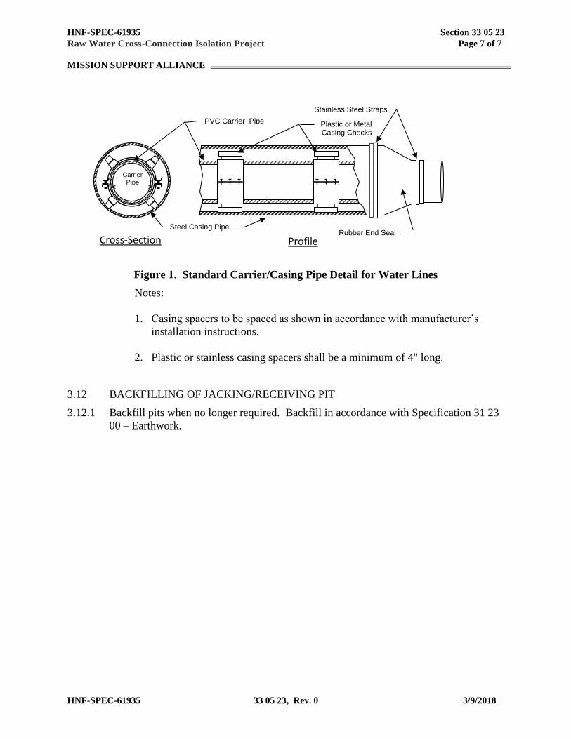
Figure 1. Standard Carrier/Casing Pipe Detail for Water Lines
Notes:
1. Casing spacers to be spaced as shown in accordance with manufacturer’s
installation instructions.
2. Plastic or stainless casing spacers shall be a minimum of 4" long.
3.12 BACKFILLING OF JACKING/RECEIVING PIT
3.12.1 Backfill pits when no longer required. Backfill in accordance with Specification 31 23
00 – Earthwork.
Carrier Pipe OD
Cross-Section Profile
Stainless Steel Straps
Plastic or Metal Casing Chocks
Rubber End Seal Steel Casing Pipe
PVC Carrier Pipe
HNF-SPEC-61935 Section 33 10 00
Raw Water Cross-Connection Isolation Project Page 1 of 13
MISSION SUPPORT ALLIANCE
HNF-SPEC-61935 33 10 00, Rev. 0 3/9/2018
Section 33 10 00
WATER UTILITIES
PART 1 – GENERAL
1.1 SCOPE
This specification covers materials and installation of new above grade and below grade water
piping. Furnish all products and perform all labor necessary to fulfill the requirements of this
specification.
1.2 REFERENCES
The following documents and others referenced therein form part of the Contract to the extent
designated in this Section. Referenced documents are those current as of the date of this Section
unless otherwise indicated.
1.2.1 American Society of Mechanical Engineers (ASME)
ASME B16.5 Pipe Flanges and Flanged Fittings NPS ½ through NPS 24
ASME B16.9 Factory-Made Wrought Steel Buttwelding Fittings
ASME B16.21 Nonmetallic Flat Gaskets for Pipe Flanges
ASME B16.25 Buttwelding Ends
ASME B31.9 Building Service Piping
1.2.2 ASTM International (ASTM)
ASTM A53 Pipe, Steel, Black and Hot-Dipped, Zinc-Coated Welded and
Seamless
ASTM A105 Carbon Steel Forgings for Piping Applications
ASTM A106 Seamless Carbon Steel Pipe for High-Temperature Service
ASTM A126 Gray Iron Castings for Valves, Flanges, and Pipe Fittings
ASTM A193 Alloy Steel and Stainless Steel Bolting for High Temperature or
High Pressure Service and Other Special Purpose Applications
ASTM A194 Carbon Steel, Alloy Steel and Stainless Steel Nuts for Bolts for
High Pressure or High Temperature Service, or Both
ASTM A234 Pipe Fittings of Wrought Carbon Steel and Alloy Steel for
Moderate and High Temperature Service
ASTM A307 Carbon Steel Bolts, Studs, and Threaded Rod 60,000 psi Tensile
Strength
HNF-SPEC-61935 Section 33 10 00
Raw Water Cross-Connection Isolation Project Page 2 of 13
MISSION SUPPORT ALLIANCE
HNF-SPEC-61935 33 10 00, Rev. 0 3/9/2018
ASTM A536 Ductile Iron Castings
ASTM A563 Carbon and Alloy Steel Nuts
ASTM D1330 Rubber Sheet Gaskets
ASTM D1784 Rigid Poly (Vinyl Chloride) (PVC) Compounds and Chlorinated
Poly (Vinyl Chloride) (CPVC) Compounds
ASTM D2241 Poly (Vinyl Chloride) (PVC) Pressure-Rated Pipe (SDR Series)
ASTM F477 Elastomeric Seals (Gaskets) for Joining Plastic Pipe
ASTM F593 Stainless Steel Bolts, Hex Cap Screws, and Studs
ASTM F594 Stainless Steel Nuts
ASTM F1674 Joint Restraint Products for use with PVC Pipe
1.2.3 American Water Works Association (AWWA)
AWWA C104 Cement-Mortar Lining for Ductile-Iron Pipe and Fittings
AWWA C110 Ductile-Iron and Gray-Iron Fittings, 3 inches Through 48 inches,
for Water and Other Liquids
AWWA C111 Rubber-Gasket Joints for Ductile-Iron Pressure Pipe and Fittings
AWWA C116 Protective Fusion-Bonded Coatings for the Interior Surfaces of
Ductile-Iron and Gray-Iron Fittings
AWWA C151 Ductile-Iron Pipe, Centrifugally Cast, for Water or Other Liquids
AWWA C153 Ductile Iron Compact Fittings 3 inches through 24 inch and 54
inches though 64 inches for Water Service
AWWA C200 Steel Water Pipe, 6 in. and Larger
AWWA C207 Steel Pipe Flanges for Waterworks Service – Sizes 4 in. through
144 in
AWWA C210 Liquid-Epoxy Coatings and Linings for Steel Water Pipe and
Fittings
AWWA C509 Resilient Seated Gate Valves for Water Supply Service
AWWA C515 Reduced-Wall, Resilient Seated Gate Valves for Water Supply
Service
AWWA C550 Protective Epoxy Interior Coatings for Valves and Hydrants
AWWA C600 Installation of Ductile-Iron Mains and Their Appurtenances
AWWA C605 Underground Installation of Polyvinyl Chloride (PVC) and
Molecularly Oriented Polyvinyl Chloride (PVCO)
AWWA C900 Polyvinyl Chloride (PVC) Pressure Pipe and Fabricated Fittings, 4
inches through 60 inches

HNF-SPEC-61935 Section 33 10 00
Raw Water Cross-Connection Isolation Project Page 3 of 13
MISSION SUPPORT ALLIANCE
HNF-SPEC-61935 33 10 00, Rev. 0 3/9/2018
1.2.4 American Welding Society (AWS)
AWS D1.1 Structural Welding Code - Steel
1.2.5 Factory Mutual Global
FM Approval Guide Factory Mutual Approval Guide
1.2.6 National Fire Protection Association (NFPA)
NFPA 24 Installation of Private Fire Service Mains and Their Appurtenances
2016 Edition
1.2.7 Society for Protective Coatings (SSPC)
SSPC-PA 1 PA 1, Shop, Field, and Maintenance Painting of Steel
SSPC-SP10 National Association of Corrosion Engineers International, NACE
2, Near-White Blast Cleaning
1.2.8 Underwriters Laboratories (UL)
UL 262 UL Standard for Safety Gate Valves for Fire Protection Service
2004 Edition
UL 789 UL Standard for Safety Indicator Posts for Fire-Protection Service
2004 Edition
1.2.9 Washington State Department of Ecology / Washington State Department of Health
Pipeline Separation Standards Pipeline Separation Design and Installation
Reference Guide, July 2006, Publication Number
06-10-029.
1.3 SUBMITTALS
1.3.1 See Statement of Work (SOW) for submittal procedures.
1.3.2 Approval Required
1.3.2.1 Pipe Cleaning Procedures: Within 30 days from Notice of Award, submit procedures
describing the methods and materials for cleaning/flushing of installed pipe.
a. The 8 inch Export Water line shall be flushed at 10 ft/sec in accordance with
NFPA 24. Flushing procedure shall include methods for handling flush water,
i.e., pipe, valves, and fittings for filling pipeline and similar for discharging flush
water, and method for restraining above ground pipe and preventing erosion
damage.

HNF-SPEC-61935 Section 33 10 00
Raw Water Cross-Connection Isolation Project Page 4 of 13
MISSION SUPPORT ALLIANCE
HNF-SPEC-61935 33 10 00, Rev. 0 3/9/2018
b. Due to the length and volume of the Cross-Tie pipeline, typical pipe flushing with
water at 10 feet/second (NFPA 24) or 3 feet/second (AWWA C605) is not
considered to be a viable pipe cleaning method. The Subcontractor shall propose
an alternative method that uses a pipe cleaning pig or swab to progressively clean
the installed pipe. Installed and cleaned sections of pipe shall be sealed to prevent
dirt or debris from entering pipes.
1.3.2.2 Valves: Within 30 days from Notice of Award, submit Certificate of Conformance by
suppliers for each type of valve specified, indicating products supplied satisfy
applicable standards, i.e., AWWA, ASTM, etc.
1.3.2.3 Valves: Within 60 days of Notice of Award submit Vendor information for those
valves listed in the Vendor Information List at the end of this section.
1.3.3 Approval Not Required
1.3.3.1 Notification of Proposed Tie-In / Request for Tie-In Permit
1.3.3.2 Weld Examination Results
1.3.3.3 Verification of Pipeline Flushing
1.3.3.4 Verification of Hydrostatic Pressure Testing
1.3.3.5 Verification of In-Service Testing
1.3.3.6 Record Drawings / As-Built Survey
1.4 QUALITY ASSURANCE
1.4.1 Subcontractor’s Quality Control System: See Statement of Work (SOW).
1.4.2 Deliverable Documentation: The following documents and records, required by this
Section, shall be delivered to the Buyer in accordance with the SOW.
Document Paragraph
Core Drilling/Tie-ln Permit 1.5.1
Flushing Verification 3.5.1
Hydrostatic Pressure Testing 3.5.2.1
In-Service Testing 3.5.2.2
1.5 PERMITS
HNF-SPEC-61935 Section 33 10 00
Raw Water Cross-Connection Isolation Project Page 5 of 13
MISSION SUPPORT ALLIANCE
HNF-SPEC-61935 33 10 00, Rev. 0 3/9/2018
1.5.1 A Core Drilling/Tie-ln Permit is required for each element of work involving waterline
tie-in. Obtain from the Buyer and conspicuously post permit before starting work
under this Section. Notify Buyer 7 days before need. See SOW.
1.6 DELIVERY, STORAGE, AND HANDLING
1.6.1 See SOW for general requirements.
PART 2 – PRODUCTS
2.1 SUBSTITUTES
2.1.1 See SOW for substitution approvals.
2.2 BELOW GRADE PIPING MATERIALS AND APPURTENANCES
2.2.1 PVC Pipe: PVC pipe shall conform to AWWA C900, with a Dimension Ratio (DR) of
21, and shall be capable of withstanding a working pressure of 200 psi. PVC pipe shall
be manufactured from rigid polyvinyl chloride compounds in accordance with ASTM
D1784, cell class 12454. PVC pipe shall be ductile iron pipe equivalent size and shall
have belled ends for push-on type jointing. Pipe shall be supplied in minimum lengths
of 20 feet.
2.2.2 Ductile Iron Fittings for PVC Pipe: Fittings shall be ductile iron and shall conform to
AWWA C110 or AWWA C153 with a minimum rated working pressure of 250 psi.
Fittings shall be cement lined in accordance with AWWA C104 and shall be furnished
with a bituminous outside coating. In lieu of cement lining and bituminous coating,
fittings may be provided with a fusion bonded coating and lining meeting the
requirements of AWWA C116. Special adapters shall be provided as recommended by
the manufacturer to adapt the PVC pipe to mechanical jointing with cast or ductile iron
pipe fittings, or valves.
2.2.3 Ductile Iron Pipe: Ductile iron pipe shall be pressure class 250, centrifugally cast per
AWWA C151/A21.51, cement lined per AWWA C104/A21.4. Fittings shall conform
to AWWA C153/A21.53.
2.2.4 Joints: Push-on Joints in accordance with AWWA C111/A21.11; Rubber Gasket joints
for Ductile Iron Pressure Pipe and Fittings.
2.2.5 Flanges: Ductile iron pipe flanges shall conform to AWWA C207 Class E flanges, rated
at 275 psi.
2.2.6 Connections of plain end PCV or Ductile Iron pipe to flanged fittings shall be made
with EBAA Iron Inc., Megaflange Series 2100 restrained flange adapters.
HNF-SPEC-61935 Section 33 10 00
Raw Water Cross-Connection Isolation Project Page 6 of 13
MISSION SUPPORT ALLIANCE
HNF-SPEC-61935 33 10 00, Rev. 0 3/9/2018
2.2.7 Gaskets: Full Face gasket, 1/8" thick, Garlock 2400 or approved equal. Size to match
AWWA C207 Class E Standard Steel Flange.
2.2.8 Bolts and Nuts: ASTM A307, Grade A or B bolts, ASTM A563, Grade A heavy hex
nuts. For stainless steel: ASTM F593, Alloy Group 1 for stainless steel bolts and studs
and ASTM F594, Allow Group 1 for stainless steel nuts.
2.2.9 Gate Valves: Valves 4 inches in diameter and larger shall be resilient wedge type
conforming to the requirements of AWWA C509 or AWWA C515 rated for 200 psi
working pressure. Gate valves shall be manufactured by American Flow Control,
Mueller or M & H Valve.
2.2.9.1 Valves shall be provided with two O-ring stem seals with one O-ring located above and
one O-ring below the stem collar. The area between the O-rings shall be filled with
lubricant to provide lubrication to the thrust collar bearing surfaces each time the valve is
operated. At least one anti-friction washer shall be utilized to further minimize operating
torque. All seals between valve parts, such as body and bonnet, bonnet and bonnet cover,
shall be flat gaskets or O-rings.
2.2.9.2 The valve gate shall be made of cast or ductile iron having a vulcanized, synthetic rubber
coating, or a seat ring attached to the disc with retaining screws. Sliding of the rubber on
the seating surfaces to compress the rubber will not be allowed. The design shall be such
that compression-set of the rubber shall not affect the ability of the valve to seal when
pressure is applied to either side of the gate. The sealing mechanism shall provide zero
leakage at the water working pressure when installed with the line flow in either direction.
2.2.9.3 All internal ferrous surfaces shall be coated with epoxy to a minimum thickness of 4 mils.
2.2.10 Air Valves: Combination air/vacuum release valve, cast iron body in accordance with
ASTM A126, Class B with stainless steel float; inlet and outlet size 4 inch NPT,
working pressure, 250 psi, 1/8 inch orifice and a 8500 gpm system maximum flow rate.
Valve & Primer Corp. -APCO Model 149C, or an approved substitute.
2.2.11 Indicator Posts: Provide indicator posts which conform to UL 789 for gate valves
where indicated, American model IP-71 or approved substitute.
2.2.12 Casing Pipe and Accessories
2.2.12.1 Casing for the 30” Cross-Tie Water Line shall be PVC casing pipe which conforms to
AWWA C900, with a Dimension Ratio (DR) of 21. PVC pipe shall be manufactured
from rigid polyvinyl chloride compounds in accordance with ASTM D1784, cell class
12454.
HNF-SPEC-61935 Section 33 10 00
Raw Water Cross-Connection Isolation Project Page 7 of 13
MISSION SUPPORT ALLIANCE
HNF-SPEC-61935 33 10 00, Rev. 0 3/9/2018
2.2.12.2 Casing Spacers:
a. Spacer Band Material: Carbon steel coated with fusion bonded epoxy or Type 304
stainless steel.
b. Spacer Width: As recommended by spacer manufacturer for the specific
application.
c. Spacer Runners: Suitable for supporting the weight of the carrier pipe and
manufactured of material having a low coefficient of friction and designed to
support the carrier pipe without damage or excessive wear.
d. Size: Sufficient to provide a minimum clearance of 2 inches between outside of
carrier pipe bells or couplings and inside of casing.
2.2.12.3 Joint Restraints: Provide joint-restraints for PVC push joints within Casing. Joint
restraints shall be compatible with AWWA C900 PVC DR21 pipe; APS - Model SS1
or S1, Cascade waterworks -Style CCS, CCI Pipeline System- Model CSS8 or equal.
2.2.12.4 End Boot/ Seal: Conical shaped, seamless pull-on or wrap around compatible with
casing spacer design.
a. Advance Products and Systems, Inc., Lafayette, LA.
b. Cascade Waterworks Mfg. Co., Yorkville, IL.
c. Pipeline Seal and Insulator, Inc. (PSI), Houston, TX.
2.3 ABOVE GRADE PIPING MATERIALS
2.3.1 Steel Pipe: Steel pipe shall conform to AWWA C200, Section 2.1, manufactured to
meet the requirements of ASTM A53, Grade B, Schedule 40 standard weight, beveled
ends, electric resistance welded or seamless. Fittings shall be standard weight, ASTM
A234, ANSI B16.9, Grade “WPB”.
2.3.2 Flanges: Steel flanges shall be carbon steel, ASTM A105, 150# weld neck or slip-on,
flat face or raised face to meet ANSI B16.5.
2.3.3 Gaskets: Full Face gasket, ASME B16.21, Class 150, 1/8" thick. Aramid fibers with
nitrile binder, Garlock 3000 or approved equal.
2.3.4 Bolts and Nuts: Alloy threaded stud, ASTM A193 Gr. B7 with heavy hex nuts, ASTM
A194 Gr. 2
2.4 COATING FOR BURIED METAL COMPONENTS
2.4.1 Coat metal components to be buried with a coal tar epoxy bituminous coating in
accordance with AWWA C210, Carboline Bitumastic 300 M or approved substitute.
HNF-SPEC-61935 Section 33 10 00
Raw Water Cross-Connection Isolation Project Page 8 of 13
MISSION SUPPORT ALLIANCE
HNF-SPEC-61935 33 10 00, Rev. 0 3/9/2018
PART 3 – EXECUTION
3.1 INSTALLATION
3.1.1 General
3.1.1.1 Install piping and piping accessories in accordance with AWWA C600 or C605 (where
applicable), the Drawings, the manufacturer's instructions and this Section. Crossings
of existing Sanitary Water Lines must meet Washington State Pipeline Separation
Standards.
3.1.1.2 Keep piping systems clean during installation. Once fabrication has started on length
of pipe, plug or cap open ends when installation is not in progress.
3.1.1.3 Install with alignment and grade as shown on the Drawings and as specified in this
Section.
3.1.1.4 Vent valve assembly shall be located as shown on the Drawings.
3.1.1.5 Coat carbon steel components that are buried, such as tie rods, fasteners, clamps, etc.
with Carboline Bitumastic 300M. Allow time for Carboline coating to dry before
backfilling. Follow the manufacturer's instructions for mixing, applying, and drying
Carboline.
3.1.1.6 Provide concrete thrust restraint at tees and bends in accordance with NFPA 24, Article
10.6.
a. Concrete thrust blocks – location and bearing areas as shown on drawings.
3.1.2 PVC Pipe
3.1.2.1 Handle and install PVC pipe in accordance with AWWA C605 and the manufacturer's
instructions.
3.1.2.2 Provide thrust restraints as specified above.
3.1.3 Carbon Steel Pipe
3.1.3.1 After cutting, ream pipe to nominal inside diameter. Remove burrs from mating
threads in threaded piping before assembly.
3.1.3.2 Close or butt nipples are not permitted.
HNF-SPEC-61935 Section 33 10 00
Raw Water Cross-Connection Isolation Project Page 9 of 13
MISSION SUPPORT ALLIANCE
HNF-SPEC-61935 33 10 00, Rev. 0 3/9/2018
3.1.3.3 Make joints in threaded piping systems with specified joint sealant. Apply sealant to
male threads only.
3.1.4 Perform specified flushing and leak/pressure testing before coating application.
3.1.5 Welding
3.1.5.1 Steel Support Welding: Qualify processes and operators according to AWS D1.1,
"Structural Welding Code--Steel".
3.1.5.2 Steel Pipe Welding: Qualify processes and operators according to ASME Boiler and
Pressure Vessel Code: Section IX, "Welding and Brazing Qualifications”.
a. Comply with provisions in ASME B31 Series, "Code for Pressure Piping".
b. Certify that each welder has passed AWS qualification tests for welding processes
involved and that certification is current.
3.1.5.3 Direct welded connections shall not be made to valves, strainers, equipment, etc.,
unless specifically noted in drawings; use welding flanges, etc.
3.1.5.4 All welds shall be 100% penetration and subject to dye penetrant testing of 10% of all
pipe welds.
3.1.5.5 All butt welding shall be done on prepared ends shaped by machining to the
requirements of ASME B16.25. Welding electrodes shall be in accordance with ASME
and AWS specifications selection governed by piping materials. Fillet socket welds
shall have a minimum length and height of fillet equal to 1-1/4" times pipe wall
thickness, but in no case less than 1/8". Weld-on branch fittings are acceptable for
branch outlets only if the main is 2" nominal size and larger and provided that the outlet
is 2 or more sizes smaller than the main.
3.2 PIPE CASING SPACERS AND END SEALS
3.2.1 Install Casing Spacers, restrained type, following manufactures instructions. Place
spacers at 5-feet maximum spacing in either the centered or non-centered pipe position.
3.2.2 Install joint restraint spacers for all bell and spigot, gasket joints located within the pipe
encasement.
3.2.3 Place and secure end boots/ seals on each end of casing pipe with 3/4"-wide (minimum)
stainless steel bands following manufactures instructions. End boot seal design shall be
made to fit the centered or non-centered pipe position.
3.3 EXTERIOR PROTECTIVE COATING FOR CARBON STEEL PIPE
HNF-SPEC-61935 Section 33 10 00
Raw Water Cross-Connection Isolation Project Page 10 of 13
MISSION SUPPORT ALLIANCE
HNF-SPEC-61935 33 10 00, Rev. 0 3/9/2018
3.3.1 Complete visual NDE and leak/pressure testing before application of grout or exterior
protective coating.
3.3.2 Steel pipe used for casings or encasements do not need to be coated.
3.3.3 Above grade pipe and fittings shall be exterior coated. Pipe and fittings shall be coated
in accordance with AWWA Standard C210. Coatings shall be applied by spray unless
stated otherwise by the job specifications or local regulations. If spray application is
not allowed, the coatings shall be applied by brush. Unless otherwise specified, the
painting system shall be as follows:
3.3.3.1 Surface Preparation: Surfaces to be painted shall be thoroughly cleaned prior to the
application of paint. Surface preparation required by this specification is as designated
by SSPC-SP10 (Steel Structures Painting Council).
3.3.3.2 Brush Off Blast Cleaning: Surfaces to be coated shall be prepared by removing all
visible oil, dirt, dust, loose mill scale, loose rust and loose paint by sand or grit air
blasting. Abrasives which peen the surface (i.e.; steel shot) shall not be used. Tightly
adherent mill scale, rust and paint may remain on the surface. Mill scale, rust and paint
are considered highly adherent if they cannot be removed by lifting with a dull putty
knife. Oils, grease or other soluble contaminants shall first be removed by solvent
cleaning as per SSPC-PA 1.
3.3.3.3 Primer Coat: One coat of primer consisting of a single package moisture cured epoxy
phenolic primer shall be applied. Epoxy phenolic primer shall have a minimum of 50
percent solids by volume. Primer shall be able to be applied at 6.0 mils dry film
thickness (DFT) in one coat.
3.3.3.4 Final Coat: Minimum of one coat of Epoxy Phenolic (semi-gloss) or (gloss). The color
shall be as specified by owner. Epoxy Phenolic shall be lead free. Epoxy Phenolic shall
have a minimum of 58 percent solids by volume for semi-gloss or 74 percent solids for
gloss. Epoxy shall be able to be applied at 6.0 mils. DFT in one coat.
3.4 FIELD QUALITY CONTROL
3.4.1 Weld Examination: Perform visual examination of piping system welds in accordance
with ASME B31.9, paragraph 936.4, and 936.4.1; and inspect welds per 936.6.1 and
936.6.2. Record results.
3.4.2 Cleaning/flushing and testing installed pipe shall be performed by the Subcontractor
and witnessed by the Buyer, unless otherwise directed by the Buyer.
3.4.2.1 Clean the Cross-Tie Water Line and maintain free of dirt and debris in accordance with
the approved cleaning procedure.
HNF-SPEC-61935 Section 33 10 00
Raw Water Cross-Connection Isolation Project Page 11 of 13
MISSION SUPPORT ALLIANCE
HNF-SPEC-61935 33 10 00, Rev. 0 3/9/2018
3.4.2.2 Flush the 8 inch Export Water Line in accordance with NFPA 24 and the approved
flush procedure. Use raw water for flushing raw water lines. With piping full, use a
flushing velocity of 10 ft/s minimum, or the maximum which can be achieved with the
water system.
3.4.3 Hydrostatic Pressure Testing
3.4.3.1 Installed water lines shall be filled with water and pressure tested. Pipes or pipe
sections shall maintain 200 psi plus or minus 5% without interruption for a minimum of
2 hours plus any additional time required for inspection of pipe being tested. Test
water mains for 2 hours in accordance with NFPA 24.
3.4.3.2 Install a temporary pressure relief valve during testing of each pipe section being tested.
Relief valve shall have a discharge capacity of 125% minimum of pressurizing device
capacity and be set to operate at 110% maximum of test pressure. Demonstrate relief
valve operation at the following times.
a. Before relief valve is attached to system for each series of leak tests.
b. Whenever the Buyer has cause to question operating accuracy of relief valve.
3.4.3.3 Before applying test pressure, the Subcontractor may backfill or install restraining
devices to prevent distortion and displacement of piping. Pipeline joints are not
required to be visible during pressure testing.
3.4.3.4 Verify that air has been expelled from piping before applying pressure.
3.4.3.5 During pressure testing of the 30 inch pipeline, make-up water may be added to the
pipeline at a rate of 2.48 gallons/hour per 1,000 ft of pipeline.
3.4.3.6 Perform tests as specified herein in the presence of the Buyer, unless otherwise
instructed in writing, and after lines have been cleaned/flushed.
3.4.3.7 Repair unsatisfactory joints and retest by same method.
3.4.3.8 In-Service Testing: Perform in accordance with ASME B31.9, paragraphs 937.3 and
937.5. Test 8-inch and smaller piping and connections or other new piping as directed
by the Buyer for 30 minutes minimum at normal operating system pressure, with no
visible leaks or loss of test pressure. Examine joints, fittings, and other potential leak
sources during testing, (prior to backfilling trench). Repair detectable leaks and retest
by same method.
3.5 DOCUMENT FIELD INSPECTIONS AND TESTS
3.5.1 Flush in accordance with article 3.4.2 and document results.
HNF-SPEC-61935 Section 33 10 00
Raw Water Cross-Connection Isolation Project Page 12 of 13
MISSION SUPPORT ALLIANCE
HNF-SPEC-61935 33 10 00, Rev. 0 3/9/2018
3.5.2 Document leak/pressure testing of piping system in accordance with paragraphs 3.4.3.5
and 3.4.3.6.
3.5.2.1 Verify completion of flushing and hydrostatic test of new water lines and document
results on "Subcontractor's Materials and Test Certificate," a NFPA 24 form furnished
by the Buyer. Under "Description" describe piping system in sufficient detail to define
segment of pipe being tested.
3.5.2.2 Verify in-service test of tie-in and service connections and document results.
3.6 RECORD (RED-LINE) DRAWINGS
3.6.1 Maintain a current set of Record Drawings on site to document horizontal and vertical
location of the newly installed pipeline, valves, fittings and angle points and any
existing buried utilities. Identify existing utilities by indicating the type of material
encountered, (i.e., cable, conduit, pipe, concrete, etc.) outside diameter or depth or any
other distinguishing features.
3.6.2 After laying underground piping and before backfilling trench, record top of pipe
elevations at 100 feet maximum intervals, and all angle points, valve installations, etc.
Exception, record top of pipe casing elevations at centerline and shoulders, (i.e. end of
casing), and top of export pipe at each end near casing, (+/- foot).
3.6.3 In lieu of waiting for record survey prior to backfilling, provide alternate method
approved by the Buyer for obtaining required record survey data. Recorded top of pipe
elevations, with corresponding coordinates and stationing, shall be used to develop an
As-Built profile and location of the installed water lines.
3.6.4 After pipe trench has been backfilled and compacted, record the finished grade profile
along the recorded centerline of the installed pipeline, again at 100 foot maximum
intervals, with corresponding coordinates and stationing. Prior to paving, record
subgrade elevations at all road crossings. This information shall be used to verify that
the minimum cover requirements have been satisfied. Insufficient cover shall be
corrected before paving operations or final ballast rock placement begins or
stabilization is placed at the Subcontractor's expense.
3.6.5 Installation of air vents shall be constructed in accordance with the Buyer’s standard air
vent detail (see Drawings).
3.6.6 Prepare the collected Drawing data and As-Built profiles within 3 days of backfilling
pipe trench. A State of Washington Licensed Land Surveyor shall certify survey data
collected.

L-8
94
-C1
S
ecti
on
33
10 0
0
Ra
w W
ate
r C
ro
ss-C
on
necti
on
Iso
lati
on
Pro
ject
Pa
ge
13
of
13
MIS
SIO
N S
UP
PO
RT
AL
LIA
NC
E
L-8
94
-C1
33
10 0
0, R
ev. 0
3
/9/2
018
Pro
ject
No
.: L
-894
V
END
OR
INFO
RM
ATI
ON
LIS
T P
roje
ct T
itle
: R
aw W
ater
Cro
ss-C
on
nec
tio
n
Iso
lati
on
Pro
ject
(“
X”
Ind
icat
es R
equ
ired
Dat
a)
Spec
ific
atio
n S
ecti
on
: 33
10
00
1
2
3
4
5 V
END
OR
INFO
RM
ATI
ON
(V
I)
EPN
D
ESC
RIP
TIO
N
REF
EREN
CE
DR
AW
ING
SP
ECIF
ICA
TIO
N
PA
RA
GR
AP
H
Dimensional Drawings
Equipment Weights
Specifications
Material Description
Certified Test Data
Circuit or Control Diag.
Inst
ruct
ion
s
Spare Parts List
Data Sheets
Illustrative Cuts
Installation
Operation
Maintenance
Mat
eria
ls
Gat
e V
alve
s H
-2-8
373
44-
1
H-2
-83
734
5-1
2.2
.9
X
X
X
X
X
A
ir V
ent
Ass
emb
ly
H-2
-83
734
2-1
2.2
.10
X
X
X
X
D
rain
Gat
e V
alve
s H
-2-8
373
42-
1 2
.2.9
X
X
X
X
Sa
nit
ary
Gat
e V
alve
s H
-2-8
373
45-
1 H
-2-8
373
46-
1 2
.2.9
X
X
X
X
In
dic
ato
r P
ost
s H
-2-8
373
44-
1
H-2
-83
734
5-1
2.2
.11
X
X
X
X

HNF-SPEC-61935 Section 33 30 10
Raw Water Cross-Connection Isolation Project Page 1 of 6
MISSION SUPPORT ALLIANCE
HNF-SPEC-61935 33 30 10, Rev. 0 3/9/2018
Section 33 30 10
PRECAST VAULTS AND MANHOLES
PART 1 – GENERAL
1.1 SCOPE
This specification covers the installation of precast vaults and manhole sections for valves for the
Cross-Tie water line. Furnish all labor, material, and equipment to construct vaults with access
manholes at locations shown on the drawings.
1.2 REFERENCES
The following documents and others referenced therein form part of the Contract to the extent
designated in this Section. Referenced documents are those current as of the date of this Section
unless otherwise indicated.
1.2.1 American Association of State Highway and Transportation Officials (AASHTO)
AASHTO M 43 Sizes of Aggregate for Road and Bridge Construction
1.2.2 ASTM International
ASTM A48 Gray Iron Castings
ASTM C270 Mortar for Unit Masonry
ASTM C443 Joints for Concrete Pipe and Manholes, Using Rubber Gaskets
ASTM C478 Circular Precast Reinforced Concrete Manhole Sections
ASTM C858 Standard Specification for Underground Precast Concrete Utility
Structures
ASTM C923 Resilient Connectors between Reinforced Concrete Manhole
Structures, Pipes, and Laterals
ASTM C990 Joints for Concrete Pipe, Manholes, and Precast Box Sections
Using Preformed Flexible Joint Sealants.
1.2.3 Washington State Department of Transportation (WSDOT)
M 41-10 Standard Specifications
1.3 SUBMITTALS
1.3.1 See Statement of Work (SOW) for submittal procedures.
HNF-SPEC-61935 Section 33 30 10
Raw Water Cross-Connection Isolation Project Page 2 of 6
MISSION SUPPORT ALLIANCE
HNF-SPEC-61935 33 30 10, Rev. 0 3/9/2018
1.3.2 Approval Required
1.3.2.1 Fill mix: Before ordering, submit fill materials, mix design, and mix proportions.
Identify each material to be used in fill, including amount, by weight, to be utilized in
each yd3 of plastic mix.
1.3.2.2 Test data: Before mixing, submit laboratory trial batches, or field trial data, to verify
mix compressive strength.
1.3.3 Approval Not Required
1.3.3.1 Installation Inspection Reports
1.4 QUALITY ASSURANCE
1.4.1 Subcontractor’s Quality Control System: See Statement of Work (SOW).
1.5 DELIVERY, STORAGE, AND HANDLING
1.5.1 Handle precast concrete manhole sections carefully to prevent cracking or chipping.
1.5.2 Inspect metal items upon arrival and segregate as to types, functions, and sizes. Store
off of the ground in a manner affording easy accessibility and not causing excessive
rusting or coating with grease or other objectionable materials.
1.5.3 Store jointing materials and rubber gaskets under cover and out of direct sunlight.
PART 2 – PRODUCTS
2.1 SUBSTITUTES
2.1.1 See Section SOW for general requirements
2.2 PRECAST CONCRETE VAULTS
2.2.1 Precast concrete vaults shall conform to the project drawings. Precast concrete vaults
may be sectional structures and shall meet the requirements of ASTM C858.
2.2.2 Vaults and vault tops shall be capable of supporting HS20 traffic loads.
2.2.3 Vaults shall have cast openings for pipelines with connectors cast into openings.
Connectors shall conform to ASTM C923.
HNF-SPEC-61935 Section 33 30 10
Raw Water Cross-Connection Isolation Project Page 3 of 6
MISSION SUPPORT ALLIANCE
HNF-SPEC-61935 33 30 10, Rev. 0 3/9/2018
2.2.4 All sections of vault structures shall have lifting lugs capable of supporting the section.
2.3 PRECAST CONCRETE MANHOLE RISERS, GRADE RINGS, AND TOP
2.3.1 Precast concrete manhole riser sections shall conform to the project drawings and the
requirements of ASTM C478. The risers shall be monolithic.
2.3.2 The circumferential reinforcement for the manhole sections shall consist of welded wire
fabric per ASTM C478.
2.3.3 The manhole risers and grade rings shall be used to bring the top and manhole cover to
the required elevation.
2.3.4 All sections shall contain factory-installed lifting keys or lugs. Lifting holes through
the manhole structure shall not be permitted.
2.3.5 Each joint shall be a single-step concrete joint design type with a gasket in accordance
with ASTM C443, and one ring of butyl mastic sealant. Gasket shall be adhered to the
concrete with an adhesive as recommended by manufacturer.
2.3.6 All precast reinforced concrete manhole sections specified herein shall be inspected by
the Buyer. All materials that fail to conform to these specifications shall be rejected.
After delivery to the site, any materials that have been damaged in transit or are
otherwise unsuitable for use in the work shall be rejected and removed from the site by
the Subcontractor at no cost to the Buyer.
2.3.7 Precast Concrete Grade Rings and Top
2.3.7.1 Precast concrete (grade) rings of two, three, four, and six inch thickness shall be
manufactured in accordance with ASTM C478.
2.3.7.2 Rings shall have precast bolt holes matching flat top section. Flat top shall have an
opening diameter which matches and supports the full manhole frame.
2.3.7.3 Field molding of grade rings is prohibited.
2.3.8 Mortar
2.3.8.1 Mortar shall be per ASTM C270 and composed of one part Portland cement and two
parts sand (volumetric measure) thoroughly mixed in a tight box, with water added
gradually and mixed continually until mortar has attained the proper consistency for
use; prepared only in such quantities as needed for immediate use; mortar mixed for
more than 30 minutes, retempered, or previously set will not be allowed.
HNF-SPEC-61935 Section 33 30 10
Raw Water Cross-Connection Isolation Project Page 4 of 6
MISSION SUPPORT ALLIANCE
HNF-SPEC-61935 33 30 10, Rev. 0 3/9/2018
2.3.9 Manhole Frames and Covers
2.3.9.1 Cast iron manhole frames and covers shall meet the requirements of the Drawings and
ASTM A48 for Class 30 gray iron. Castings shall be sound, smooth, clean, and free
from blisters and other defects. In addition, the covers shall be machined so that they
rest securely in the frames with no rocking, and such that they are in contact with frame
flanges for the entire perimeter of the contact surfaces.
2.3.9.2 No casting will be accepted which weighs less than 95 percent of the design weight.
Shop drawings must indicate the design weight and provide sufficient dimensions to
permit checking. All castings shall be thoroughly cleaned in the shop and given two
coats of approved bituminous paint before rusting begins.
2.3.10 Butyl Mastic Sealant
2.3.10.1 The sealant shall be used when joining the casting frame to the precast manhole and for
all manhole adjustments to provide a watertight structure. The sealing compound shall
be in conformance with ASTM C990 and produced from blends of refined hydrocarbon
resins and plasticizing compounds reinforced with inert mineral filler, and shall contain
no solvents, irritating fumes, or obnoxious odors. It shall be supplied in extruded rope
form of suitable cross section and in such sizes as to seal the joint space. Use 2
complete ropes at each joint.
2.3.11 Pipe Connection to Manhole
2.3.11.1 Pipe opening seals shall be cast integrally with manhole section, sized to fit pipe
specified, and set at correct elevation and location. Resilient connectors shall meet the
requirements of ASTM C923.
PART 3 – EXECUTION
3.1 EXCAVATION AND BACKFILL
3.1.1 Excavation and backfill shall conform to the applicable requirements of Specification
31 23 00 - Earthwork.
3.1.2 Excavate manhole area to allow for a minimum six inch bedding of AASHTO M43 No.
57 aggregate properly leveled and compacted.
3.2 MANHOLE FOUNDATIONS
HNF-SPEC-61935 Section 33 30 10
Raw Water Cross-Connection Isolation Project Page 5 of 6
MISSION SUPPORT ALLIANCE
HNF-SPEC-61935 33 30 10, Rev. 0 3/9/2018
3.2.1 Dewater sufficiently to maintain the ground water level at or below the bottom of the
manhole foundation prior to and during placement of the foundation. Obtain an
adequate foundation for all manhole structures by removing and replacing unsuitable
material with well-graded granular material, by tightening with coarse rock, or by such
other means as provided for foundation preparation of the connected sewers or as
directed by the Buyer.
3.3 MANHOLE INSTALLATION
3.3.1 Construct manholes as shown on the Drawings.
3.3.2 Provide uniform bedding of the bottom section to prevent uneven loading. Install
gaskets and joint sealants in accordance with manufacturer’s recommendations to
produce a watertight structure.
3.3.3 All precast concrete ring sections and top sections shall fit together readily to permit
effective jointing. Joints between adjacent sections of all manholes shall be made with
two strips of approved preformed joint sealing compound.
3.3.4 All pipes entering the manhole shall be secured by a rubber boot provided in a cored or
precast hole of the proper diameter and in conformance to ASTM C923.
3.3.5 Form channels to accommodate flow path of incoming and outgoing pipes. Channels
shall be rounded and troweled smooth with a consistent grade through the invert. For
changes in direction between incoming and outgoing pipe, make a circular curve in the
manhole invert of as large a radius as possible.
3.3.6 Thoroughly wet and completely fill all precast manhole joints with non-shrinking grout
to a smooth finish, both inside and outside of the manhole.
3.3.7 Manholes shall be constructed such that their walls are plumb.
3.4 FRAMES AND COVERS
3.4.1 Cast iron frames and covers shall be set at the required elevation and properly bonded
to the masonry with two rings of butyl mastic sealant and anchor bolts.
3.4.2 Manhole rim elevations shall be set at grade in traffic areas and finished landscaped
areas (finished grade is at the top of mulch in finished landscape areas), shall be set at 3
inches above grade in nonfinished landscaped areas, and to be set at 2 feet above finish
grade in nontraffic and nonlandscaped areas.
HNF-SPEC-61935 Section 33 30 10
Raw Water Cross-Connection Isolation Project Page 6 of 6
MISSION SUPPORT ALLIANCE
HNF-SPEC-61935 33 30 10, Rev. 0 3/9/2018
3.4.3 Wherever manholes are constructed in paved areas, the top surface of the frame and
cover shall conform to the exact slope, crown, and grade of the adjacent pavement.
3.5 MANHOLE INSTALLATION INSPECTION
3.5.1 The Subcontractor shall inspect all installation activities and submit an inspection
report which documents that manholes were installed in accordance with the
requirements of this specification.
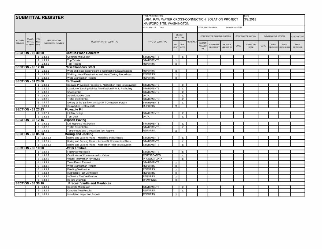
CONTRACTOR
INFO
ONLY
GOV'T
APPR
SUBMIT
NEEDED
BY
APPROVAL
NEEDED BY
MATERIAL
NEEDED BYCODE
SUBMITTAL
DATECODE
DATE
RECEIVED
DATE
RETURNED
DATE
RECEIVED
1 1.3.2.1 Concrete Mix Design STATEMENTS x2 1.3.3.1 Trip Tickets STATEMENTS x3 1.3.3.2 Test Results REPORTS x
1 1.3.2.1 Weld and Inspection Personnel Certifications/Qualifications REPORTS x2 1.3.2.2 Welding, Weld Examination, and Weld Testing Procedures REPORTS x3 1.3.2.3 Weld Examination Results REPORTS x
1 1.3.2.1 Damage Prevention Procedure / Notification Prior to Excavation STATEMENTS x2 1.3.2.2 Location of Existing Utilities / Notification Prior to Pot-holing STATEMENTS x
1.3.2.3 Shoring Plan STATEMENTS x4 1.3.2.4 As-built Survey Data DATA x5 1.3.2.5 Traffic Control Plan STATEMENTS x6 1.3.2.6 Identity of the Earthwork Inspector / Competent Person STATEMENTS x7 1.3.3.1 Compaction Test Reports REPORTS x
1 1.3.2.1 Fill Mix Design STATEMENTS x2 1.3.2.2 Test Data DATA x
1 1.3.2.1 Lab Reports / Mix Design STATEMENTS x2 1.3.2.2 Traffic Control Plan STATEMENTS x3 1.3.3.1 Temperature and Compaction Test Reports REPORTS x
1 1.3.2.1.a Boring and Jacking Plans - Materials and Methods STATEMENTS x2 1.3.2.1.b Boring and Jacking Plans - Access Pit Construction Plans STATEMENTS x3 1.3.2.1.c Boring and Jacking Plans - Notification Prior to Excavation STATEMENTS x
1 1.3.2.1 Flushing Procedures STATEMENTS x2 1.3.2.2 Certificates of Conformance for Valves CERTIFICATES x3 1.3.2.3 Vendor Information for Valves PRODUCT DATA x4 1.3.3.1 Tie-in Permit Request STATEMENTS x5 1.3.3.2 Weld Examination Results REPORTS x6 1.3.3.3 Flushing Verification REPORTS x7 1.3.3.4 Hydrostatic Test Verification REPORTS x8 1.3.3.5 In-Service Test Verification REPORTS x9 1.3.3.6 Record Drawings DRAWINGS x
1 1.3.2.1 Concrete Mix Design STATEMENTS x2 1.3.2.2 Concrete Test Results REPORTS x3 1.3.3.1 Installation Inspection Reports REPORTS x
CONTRACTOR SCHEDULE DATES
SECTION - 05 12 10 Miscellaneous Steel
SECTION - 31 23 00 Earthwork
SECTION - 33 10 00 Water Utilities
SECTION - 31 23 23 Flowable Fill
SECTION - 32 12 16 Asphalt Paving
SECTION - 33 05 23 Boring and Jacking
SECTION - 03 30 00 Cast-In-Place Concrete
SECTION - 33 30 10 Precast Vaults and Manholes
SUBMITTAL REGISTER
CONTRACT NUMBER N40083-14-D-0016
ACTIVITY
NUMBER
CONTRACTOR ACTION
CONTRACTOR TBD
GOVERNMENT ACTION
DATE
3/9/2018
TITLE AND LOCATION
L-894, RAW WATER CROSS-CONNECTION ISOLATION PROJECT
HANFORD SITE, WASHINGTON
TRANS-
MITTAL
NUMBER
TYPE OF SUBMITTAL
CLASSI-
FICATION
REVIEWER
ITEM
NUM-
BER
SPECIFICATION
PARAGRAPH NUMBERDESCRIPTION OF SUBMITTAL
3