historical background of steel bridges - prefabricated steel bridge systems_ final report -...
TRANSCRIPT

7/29/2019 Historical Background of Steel Bridges - Prefabricated Steel Bridge Systems_ Final Report - Prefabricated Steel Bridge Systems_ Final Report - Publications - P…
http://slidepdf.com/reader/full/historical-background-of-steel-bridges-prefabricated-steel-bridge-systems 1/27
Prefabricated Bridge Elements and Systems
FHWA > Bridge > PBES > Publications > Prefabricated Steel Bridge Systems: Final Report > Historical Background Of Steel Bridges
PBES
Innovative
Projects
Research
Publications
Videos
Events
<<Previous Contents Next>>
Prefabricated Steel Bridge Systems: Final Report
2. Histori cal Background Of Steel Bridges
This chapter presents a background review of the historical reference and design forthe current day applications of prefabricated steel bridges. Many types of prefabricated steel bridge systems have been used in rehabilitation projects toreplace deteriorating bridges. Numerous manufacturers currently offer prefabricatedbridges to accommodate applications including:
Temporary Bridges: As an alternative to costly detours, maintenance of traffic, and
increased traffic volume, prefabricated steel bridges are utilized to divert traffic duringbridge repair, rehabilitation, construction, or replacement. These bridges are installed
as a temporary structure during construction and then disassembled and stored untilused again as a temporary structure.
Emergency Bridges also are needed from a security standpoint, and due to
man-made non-terrorist hazards like ship impact, truck impact, fire, and blast. Naturaldisasters such as hurricanes, mudslides, fires, and tornados can destroy a bridge bywashout or collapse. Typical prefabricated bridges can be erected much faster thanthe time of constructing a cast-in-place structure. Moreover, with the increased threatto our nation's infrastructure due to terrorism, these systems could be utilized in atime of national emergency.
Permanent Bridges: A permanent structure requires a design service life of 75years in accordance with the AASHTO LRFD Bridge Design Specifications, thirdedition (2004). A major objective of this study is to provide recommendations that willincrease the use of prefabricated steel bridges as permanent bridges.
The systems in use today have evolved greatly from the original designs conceivedover 60 years ago. Today, the designs are longer, wider, stronger, and more durable.
This chapter presents the development history and discusses common practices inuse today as well as innovations that are present in the prefabricated bridge industry.Although some of the systems are relatively costly, allowance for the rapidreplacement of decks or entire superstructures makes them an attractive option.Also, as they gain widespread acceptance and use, mass production of the systemswill make them more economical.
The involvement of the prefabrication industry in steel bridge construction is primarilyin providing components that are prefabricated in a factory. Through mass production
and reduction of on-site construction time, economical benefits are most oftenachieved.
Innovative bridge designers and builders are finding ways to prefabricate entiresegments of the superstructure. Prefabricated composite units include steel elementsprefabricated with a composite deck, transported to the project site, and thenerected in place. Prefabricated systems could also be constructed in the right-of-wayalong side of the bridge and then lifted into place. Prefabrication on this scale offersadvantages of easier constructability, reduced on-site construction time and thereforereduced maintenance of traffic control and detours to the traveling public andtransportation of goods.
2.1 Superstructures
The first truly modular prefabricated steel bridge systems were developed beginningin the 1930's in order to meet the needs of the British military in remote environments.
The main members are trusses composed of "panels" that are bolted together. Theflooring then spans between truss members with a combination of transverse floorbeams and steel decking or grating. These systems are hereby referred to as
MoreInformation
Highwaysfor LIFE
Contact
Reggie Holt
Office of Bridges andStructures202-366-4596
E-mail Reggie
torical Background Of Steel Bridges - Prefabricated Steel Bridge Sy... http://www.fhwa.dot.gov/bridge/prefab/psbsreport03.cf
27 20-02-201309:37

7/29/2019 Historical Background of Steel Bridges - Prefabricated Steel Bridge Systems_ Final Report - Prefabricated Steel Bridge Systems_ Final Report - Publications - P…
http://slidepdf.com/reader/full/historical-background-of-steel-bridges-prefabricated-steel-bridge-systems 2/27
"Panel/Floor Beam/Deck Type Bridges".
The second main type of prefabricated steel bridge systems were developed duringthe 1950's as a replacement for deteriorating timber bridges. These systems useprefabricated structural steel plate girders or full-length truss members with steeldecking placed on top of these main members. These systems are hereby referred toas "Deck/Girder Bridges".
2.1.1 Temporary Bridges / Emergency Bridges
The most widely recognized form of prefabricated steel bridge is the Panel/FloorBeam/Deck type system. Truss bridges consisting of two longitudinal, vertical trusselements, transverse mounted beams attached to the bottom chord, and a deckapplied to the top of the beams have roots dating back to the first century B.C.
Callender-Hamilton Bridge System
The modern day prefabricated Panel/Floor Beam/Deck system was first patented byA.M. Hamilton in 1935. The bridge was used for quick mobilization to allow militaryaccess to remote locations or to replace destroyed bridges in times of conflict. Thedesign was centered on a series of gusset plates that allowed the direct attachmentof the longitudinal, diagonal, vertical, and cross framing members. The centralizing of connection points increased the speed of construction and also allowed identical
panels to be fabricated from identical members and then installed on site. Figures 2.1and 2.2 are original design drawings as recorded by the U.S. Patent and TrademarkOffice. This system is currently known as the Callender-Hamilton System.
Figure 2.1: A.M.Hamilton Patent Information, Elevation
U.S. Patent #: 2,024,001 - Source: http://www.uspto.gov/
Figure 2.2: A.M.Hamilton Patent Information, Gusset Plate Detail
U.S. Patent #: 2,024,001 - Source: http://www.uspto.gov/
Since the gusset plate carried the direct attachment of the vertical, diagonal, andcross members, the lateral stiffness carried by the floor beams is isolated andthereby increased. The members and connection points are modular in that manysimilar components could be erected to meet various applications. Truss panels that
are stacked on top of each other can easily be attained by attaching twoprefabricated gusset plates together, forming a central location for all connectionmembers.
This design was augmented by Sir Donald Bailey in the 1940's and is the predecessor
torical Background Of Steel Bridges - Prefabricated Steel Bridge Sy... http://www.fhwa.dot.gov/bridge/prefab/psbsreport03.cf
27 20-02-201309:37

7/29/2019 Historical Background of Steel Bridges - Prefabricated Steel Bridge Systems_ Final Report - Prefabricated Steel Bridge Systems_ Final Report - Publications - P…
http://slidepdf.com/reader/full/historical-background-of-steel-bridges-prefabricated-steel-bridge-systems 3/27
to what is now the most commonly prefabricated truss system produced, known as"The Bailey Bridge".
The Bailey Bridge
Sir Donald Bailey, a British military engineer, adapted a methodology that he patentedin 1943. The Bailey Panel Bridge System retained the same basic design, butadopted a new scheme for both the construction method and the panel connectionsystem. The criterion for the original design consisted of the following:
The basic components had to be standardized and fully interchangeable.1. The individual components had to be capable of being carried by a group of sixmen or less.
2.
The component parts had to be transportable in a three-ton military truck.3.
A bridge had to be capable of rapid erection as it was required for militaryassault purposes.
4.
The components had to be capable of producing multiple configurations in orderto provide for various loading conditions and spans.
5.
The design consists of main load-bearing side truss girders built from prefabricated,modular, rectangular panels (10 feet long and 4 feet 9 inches high center to center of pin-hole connections). The panels are pinned or bolted end-to-end at their top and
bottom chords to form a truss of the required length. Figure 2.3 details all of thecomponents that comprised the Bailey Panel Bridge System.
Figure 2.3: Standard Bailey Components
U.K. Patent #: 553,374 (1943) - Source: http://www.baileybridge.com/
Similar to the Callender-Hamilton System, the panel trusses can be placedside-by-side to form multi-truss girders and can be bolted together vertically whenmulti-truss double-height construction is required for longer spans. With this system,longer spans can be built in multiples of the panel length and load carrying capacitycan be increased by utilizing double trusses in the vertical and horizontal planes.Figure 2.4 details the five configurations achievable by using the standard Bailey
Panel Bridge System components.
Figure 2.4: Bailey Configurations
torical Background Of Steel Bridges - Prefabricated Steel Bridge Sy... http://www.fhwa.dot.gov/bridge/prefab/psbsreport03.cf
27 20-02-201309:37

7/29/2019 Historical Background of Steel Bridges - Prefabricated Steel Bridge Systems_ Final Report - Prefabricated Steel Bridge Systems_ Final Report - Publications - P…
http://slidepdf.com/reader/full/historical-background-of-steel-bridges-prefabricated-steel-bridge-systems 4/27
U.K. Patent #: 553,374 (1943) - Source: http://www.baileybridge.com/
The method of constructing the Bailey Bridge is imperative to its practicality. Thebridge can be erected in two ways: 1) launching the bridge (progressive cantilever)from one end to the other (Figure 2.5), or 2) hoisting in place by a crane. The BaileyPanel Bridge System is the design basis for all present day prefabricated Panel/Floor
Beam/Deck type bridges.
Figure 2.5: Bailey Bridge Launching Diagram
Source: http://www.baileybridge.com/
The Bailey M2 Military bridge is still in use today by the U.S. military and is also beingsold to State DOT's for use as temporary structures during rehabilitation,construction, or an emergency. Figure 2.6 below depicts a Bailey Bridge being fieldassembled by U.S. military forces.
Figure 2.6: Hand Assembly of Bailey M2 Bridge
Source: http://www.baileybridge.com/
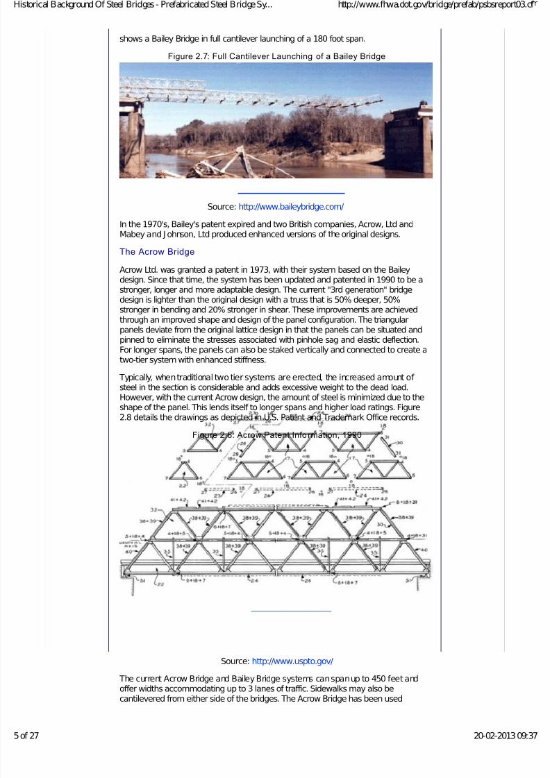
The California Department of Transportation (Caltrans) recently purchased 200 feetof Bailey M2 bridging to accommodate traffic during the construction of a permanentbridge on Highway 1. Utilizing the versatility of the M2, the bridge was then used toconstruct two temporary spans of 150 feet in length on Highway 395. Figure 2.7
torical Background Of Steel Bridges - Prefabricated Steel Bridge Sy... http://www.fhwa.dot.gov/bridge/prefab/psbsreport03.cf
27 20-02-201309:37
7/29/2019 Historical Background of Steel Bridges - Prefabricated Steel Bridge Systems_ Final Report - Prefabricated Steel Bridge Systems_ Final Report - Publications - P…
http://slidepdf.com/reader/full/historical-background-of-steel-bridges-prefabricated-steel-bridge-systems 5/27
shows a Bailey Bridge in full cantilever launching of a 180 foot span.
Figure 2.7: Full Cantilever Launching of a Bailey Bridge
Source: http://www.baileybridge.com/
In the 1970's, Bailey's patent expired and two British companies, Acrow, Ltd andMabey and J ohnson, Ltd produced enhanced versions of the original designs.
The Acrow Bridge
Acrow Ltd. was granted a patent in 1973, with their system based on the Baileydesign. Since that time, the system has been updated and patented in 1990 to be astronger, longer and more adaptable design. The current "3rd generation" bridgedesign is lighter than the original design with a truss that is 50% deeper, 50%stronger in bending and 20% stronger in shear. These improvements are achievedthrough an improved shape and design of the panel configuration. The triangularpanels deviate from the original lattice design in that the panels can be situated andpinned to eliminate the stresses associated with pinhole sag and elastic deflection.For longer spans, the panels can also be staked vertically and connected to create atwo-tier system with enhanced stiffness.
Typically, when traditional two tier systems are erected, the increased amount of steel in the section is considerable and adds excessive weight to the dead load.However, with the current Acrow design, the amount of steel is minimized due to theshape of the panel. This lends itself to longer spans and higher load ratings. Figure2.8 details the drawings as depicted in U.S. Patent and Trademark Office records.
Figure 2.8: Acrow Patent Information, 1990
Source: http://www.uspto.gov/
The current Acrow Bridge and Bailey Bridge systems can span up to 450 feet andoffer widths accommodating up to 3 lanes of traffic. Sidewalks may also becantilevered from either side of the bridges. The Acrow Bridge has been used
torical Background Of Steel Bridges - Prefabricated Steel Bridge Sy... http://www.fhwa.dot.gov/bridge/prefab/psbsreport03.cf
27 20-02-201309:37

7/29/2019 Historical Background of Steel Bridges - Prefabricated Steel Bridge Systems_ Final Report - Prefabricated Steel Bridge Systems_ Final Report - Publications - P…
http://slidepdf.com/reader/full/historical-background-of-steel-bridges-prefabricated-steel-bridge-systems 6/27
worldwide in applications where either a temporary or permanent structure isrequired.
The New J ersey Turnpike Authority selected the Acrow 700 Series Panel Bridge as atemporary bypass bridge, while an existing bridge was widened from 12 to 14 lanes.
To minimize the disruption to traffic, the contractor was permitted to close three of the12 lanes in the evening for use as a staging area. Three adjacent lanes could only beclosed for 15 minutes while the temporary bypass was installed over those lanes. Thecontractor was able to pre-assemble six Acrow 700 spans on the sides of the
highway and, with a single crane, and erect them into place within the allotted time.In another application, an Acrow 700XS Panel Bridge was installed at "Ground Zero"after the World Trade Center terrorist tragedy to assist in the recovery effort. Thebridge was a 460-foot-long by 30-foot-wide structure and was kept in place to assistin the removal of 1.8 million tons of debris. The bridge also remained in place duringthe rebuilding process on the 16-acre site. Figure 2.9 shows construction of theAcrow 700 XS Bridge with prefabricated piers using the Acrow panels used toconstruct the bridge.
Figure 2.9: Erection of t he Acrow 700XS Bridge @ Ground Zero in New York
Source: http://www.acrowusa.com/
Figure 2.10 shows an aerial view of two 1,000-foot temporary Acrow 700 SeriesPanel Bridges during installation on the Wantagh Parkway Bypass in J ones Beach,Long Island, NY.
Figure 2.10 Two 1,000 foot long Acrow 700XS Bridges Installed in New York
Source: http://www.acrowusa.com/
The Mabey Johnson Bridge
torical Background Of Steel Bridges - Prefabricated Steel Bridge Sy... http://www.fhwa.dot.gov/bridge/prefab/psbsreport03.cf
27 20-02-201309:37

7/29/2019 Historical Background of Steel Bridges - Prefabricated Steel Bridge Systems_ Final Report - Prefabricated Steel Bridge Systems_ Final Report - Publications - P…
http://slidepdf.com/reader/full/historical-background-of-steel-bridges-prefabricated-steel-bridge-systems 7/27
Mabey J ohnson, Ltd., was granted a patent in 1987 for their system, also based onthe Bailey design. Their design is identical to the lattice shape and structure of theoriginal Bailey concept, but it incorporates newly shaped elements to the panelsystem. The upper tier panels are fabricated in a transitionary shape to allow theintroduction of a sectional truss with a 2-tier system in the center to strengthen thebridge for long spans. The following Figures 2.11 and 2.12 detail the layout of theinnovative panel truss design.
Figure 2.11 Individual Mabey Johnson Truss Panel
Source: http://www.uspto.gov/
Figure 2.12: Truss Erection Scheme Showing Mabey Johnson Transitionary
Panels
Source: http://www.uspto.gov/
This design concept proved to be effective and led to the next patented Mabey J ohnson innovation. Their 2003 patent improvement added an element to reduce sagwithin long span trusses. With the new design, the bottom chord is bolted, aspreviously designed. However, the top chord consists of a facing plate in whichspacers can be added to increase the gap at the top chord. This allows for a gradualincrease in camber, thus reducing the unsightly affects of truss sag. Figure 2.13details the design elements.
Figure 2.13: Mabey Johnson Pin Connection System
Source: http://www.uspto.gov/
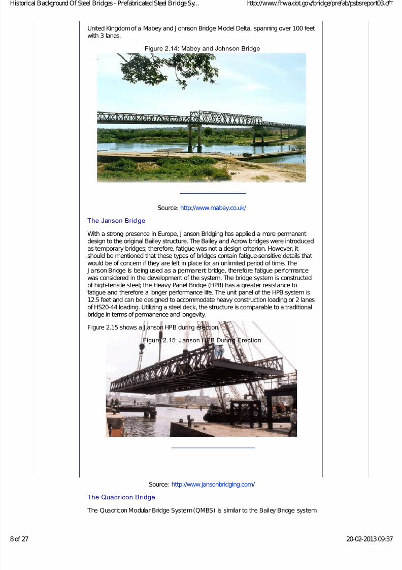
The Mabey J ohnson Bridge also has increased panels over the 10' Bailey BridgeSystem. The 15' panels are equally maneuverable by hand and a crew of five or six
can generally construct and install a 100 foot span, two-lane bridge in five days time.For example, when flash floods washed out a highway bridge in New Mexico, Mabeywas able to design a replacement within 24 hours using components alreadystockpiled by the New Mexico DOT. The 100 foot, two-lane clear span bridge waserected and serviceable within a week. Figure 2.14 shows an example from the
torical Background Of Steel Bridges - Prefabricated Steel Bridge Sy... http://www.fhwa.dot.gov/bridge/prefab/psbsreport03.cf
27 20-02-201309:37
7/29/2019 Historical Background of Steel Bridges - Prefabricated Steel Bridge Systems_ Final Report - Prefabricated Steel Bridge Systems_ Final Report - Publications - P…
http://slidepdf.com/reader/full/historical-background-of-steel-bridges-prefabricated-steel-bridge-systems 8/27

7/29/2019 Historical Background of Steel Bridges - Prefabricated Steel Bridge Systems_ Final Report - Prefabricated Steel Bridge Systems_ Final Report - Publications - P…
http://slidepdf.com/reader/full/historical-background-of-steel-bridges-prefabricated-steel-bridge-systems 9/27
but with some new design innovations. QMBS is a comprehensive system forconstructing prefabricated steel bridge superstructures from standardized, modular,mass-produced steel components. The system is an attempt at implementing a morepermanent approach to prefabricated steel design. The expected life cycle for theQMBS is 75 years. Currently, Quadricon bridges have been built in Asia over the past30 years and none have required substantial rehabilitation.
The system consists of prefabricated modular steel triangles joined by an elementreferred to as the "Unishear Connector" at each corner to form the truss. The final
truss can assume various shapes and configurations with varying load requirementsassigned per application. Spans can range from less than 100 feet to more than 500feet. Figure 2.16 shows general details of the Quadricon system.
Figure 2.16: Quadricon Modular System
Source: Civil Engineering, April 1999.
Important issues such as the durability of the Unishear connectors, fatigue properties,adherence to requirements set by the American Association of State Highway and
Transportation Officials, and whether there are fracture critical members in thestandard design will need to be investigated and addressed before implementingthese system as a permanent structure in the United States. Figure 2.17 details
several Quadricon modular units assembled together.
Figure 2.17: Quadricon Prototype
Source: http://www.quadricon.com/
Figure 2.18 demonstrates the impressive use of the Quadricon system in Asia.
Figure 2.18: Quadricon Bridge System
torical Background Of Steel Bridges - Prefabricated Steel Bridge Sy... http://www.fhwa.dot.gov/bridge/prefab/psbsreport03.cf
27 20-02-201309:37

7/29/2019 Historical Background of Steel Bridges - Prefabricated Steel Bridge Systems_ Final Report - Prefabricated Steel Bridge Systems_ Final Report - Publications - P…
http://slidepdf.com/reader/full/historical-background-of-steel-bridges-prefabricated-steel-bridge-systems 10/27
torical Background Of Steel Bridges - Prefabricated Steel Bridge Sy... http://www.fhwa.dot.gov/bridge/prefab/psbsreport03.cf
of 27 20-02-2013 09:37

7/29/2019 Historical Background of Steel Bridges - Prefabricated Steel Bridge Systems_ Final Report - Prefabricated Steel Bridge Systems_ Final Report - Publications - P…
http://slidepdf.com/reader/full/historical-background-of-steel-bridges-prefabricated-steel-bridge-systems 11/27
Source: http://www.quadricon.com/
Although the above described temporary bridge systems are widely used throughoutEurope and Asia as an acceptable solution to permanent bridge replacement, the
findings from this project indicate that the United States has been slow to adopt thesedesigns for permanent bridges which can be attributed to the lack of well establishedfatigue criteria and the extensive effort necessary to maintain these bridges.
2.1.2 Permanent Bri dges
During the 1950's, the precast concrete industry took shape and set its sights onentering the bridge market at a fast pace. It quickly became realized that a precastconcrete deck could be applied to steel longitudinal girders to replace the agingwooden bridges throughout the country. Figure 2.19 depicts a deteriorated bridgewith a prefabricated longitudinal beam system. Note that the original bridge was left inplace to avoid environmental issues associated with the bridge removal.
Figure 2.19: Longit udinal Beam Replacement Photo
Source: http://www.acrowusa.com/
Conventional Steel Girders and Concrete Deck System s
Prefabricated longitudinal beam systems can provide a quick means of replacingdamaged or deteriorated bridges. These modules can also be used to replaceindividual spans of larger structures. A good example of this type of application is therehabilitation project of I-95 bridge over J ames River in Richmond, Virginia. Thisbridge carries both of the Northbound and Southbound lanes of the roadway. In thisproject 45 of the 50 existing bridge spans were replaced with entirely new spans. Theremaining five spans consisted of four plate girder spans and one 269 foot long trussspan. The structural elements of truss span and the plate girders of the fourremaining spans were determined to be in good condition and did not require
torical Background Of Steel Bridges - Prefabricated Steel Bridge Sy... http://www.fhwa.dot.gov/bridge/prefab/psbsreport03.cf
of 27 20-02-2013 09:37

7/29/2019 Historical Background of Steel Bridges - Prefabricated Steel Bridge Systems_ Final Report - Prefabricated Steel Bridge Systems_ Final Report - Publications - P…
http://slidepdf.com/reader/full/historical-background-of-steel-bridges-prefabricated-steel-bridge-systems 12/27
replacement, however the deck slab of all five spans had significant deteriorationrequiring replacement. Therefore, only the decks of the plate girder and truss spanswere replaced using a filled-grid deck system.
All lane closure and construction work were performed at night between the hours of 11:00 PM and 6:00 AM. In the complete replacement of the 45 bridge spans, theconstruction crews saw cut large sections of concrete deck slab with three steelgirders attached and used a pair of cranes to remove and place the cut segments ontrucks for transportation off site. After bearing seats were prepared, a rubber-
treaded vehicle carried the new replacement bridge segments from a nearbyfabrication yard to the bridge site. Two cranes teamed up to lift each segment off thevehicle, and erect it in final location on the bridge piers. Using this constructionscheme, the contractor was able to replace a 3-lane wide bridge span per night of work. Figure 2.20 details the process carried out on the J ames River Bridge toreplace the 45 spans.
Figure 2.20: Lifting of Prefabricated Segments for the James River Bridge
Source: http://www.roadstothefuture.com/I95_J RB_Restoration.html
Replacing the bridge deck on the other five spans was achieved by first drilling holesand inserting lifting cables into the deck followed by saw cutting and removingsections of the deck as shown in Figures 2.21 and 2.22. Once the deck wasremoved, the filled-grid slab sections were brought out onto the bridge by a flatbedtrailer. The filled-grid slab section was then lifted and lowered into place as shown inFigure 2.23. Shear connectors were then installed along the girder flange followed bypouring polymer concrete to fill the joints as shown in Figure 2.24.
Figure 2.21: Drilling and Installing L ift ing Cables
torical Background Of Steel Bridges - Prefabricated Steel Bridge Sy... http://www.fhwa.dot.gov/bridge/prefab/psbsreport03.cf
of 27 20-02-2013 09:37

7/29/2019 Historical Background of Steel Bridges - Prefabricated Steel Bridge Systems_ Final Report - Prefabricated Steel Bridge Systems_ Final Report - Publications - P…
http://slidepdf.com/reader/full/historical-background-of-steel-bridges-prefabricated-steel-bridge-systems 13/27
Figure 2.22: Saw Cutting and Removing Existing Concrete Deck
torical Background Of Steel Bridges - Prefabricated Steel Bridge Sy... http://www.fhwa.dot.gov/bridge/prefab/psbsreport03.cf
of 27 20-02-2013 09:37

7/29/2019 Historical Background of Steel Bridges - Prefabricated Steel Bridge Systems_ Final Report - Prefabricated Steel Bridge Systems_ Final Report - Publications - P…
http://slidepdf.com/reader/full/historical-background-of-steel-bridges-prefabricated-steel-bridge-systems 14/27
Figure 2.23: Placement of New Concrete Filled Gr id Deck
Figure 2.24: Finished Deck
torical Background Of Steel Bridges - Prefabricated Steel Bridge Sy... http://www.fhwa.dot.gov/bridge/prefab/psbsreport03.cf
of 27 20-02-2013 09:37

7/29/2019 Historical Background of Steel Bridges - Prefabricated Steel Bridge Systems_ Final Report - Prefabricated Steel Bridge Systems_ Final Report - Publications - P…
http://slidepdf.com/reader/full/historical-background-of-steel-bridges-prefabricated-steel-bridge-systems 15/27
The following sections detail current innovations in prefabricated deck/girder bridgesystems, with a focus on some of the products currently available.
The Railroad Flatcar System
The concept of using railroad flatcars as temporary bridging was developed by W.H.Wattenbug of the Lawrence Livermore National Laboratory. The system, although inuse in rural areas for permanent bridging, had never been considered for use as atemporary bridge until 1994. At that point, a conceptual design was created to meetthe needs of highway loading. The modular system consisted of a flatcar acting as afoundation and supports the half flatcars that serve as columns, which in turn supporta flatcar that acts as a bent cap. The deck system consists of four flatcars,interlocked side by side. Figure 2.25 displays the concept.
Figure 2.25: Railroad Flatcar Modular System
Source: http://www.tfhrc.gov/pubrds/fall95/p95a2.htm
The system has been in use in California and is still being tested for functionality. Onedrawback to the design is the inherent need for mass amounts of cross bracing andthat the substructure is not practical for use in underwater conditions. However, it hasbeen recognized that the flatcar deck proves to be an economical solution to bridgedecking requirements for use in temporary structures.
Composite Space Truss
Space truss structures are commonly used in two-way roof and floor buildingstructure applications and have recently become a design subject for use as bridgesuperstructures. The structural reliability in terms of high stiffness/weight ratios, highstrength/weight ratios and the availability of many alternative load paths prove to be
torical Background Of Steel Bridges - Prefabricated Steel Bridge Sy... http://www.fhwa.dot.gov/bridge/prefab/psbsreport03.cf
of 27 20-02-2013 09:37

7/29/2019 Historical Background of Steel Bridges - Prefabricated Steel Bridge Systems_ Final Report - Prefabricated Steel Bridge Systems_ Final Report - Publications - P…
http://slidepdf.com/reader/full/historical-background-of-steel-bridges-prefabricated-steel-bridge-systems 16/27
equally effective in bridge design. One such example of a composite space trussconsists of a cylindrical steel tube truss design, fabricated in equilateral trianglesforming a triangular shaped truss with a pre-fabricated deck. Although this design hasbeen utilized primarily in Europe as a temporary bridge, extensive research anddevelopment has led to a design that can be considered as a permanent structure.Initial cost is a disadvantage to this type of structure; however, the standardization of components and methods has yet to be fully investigated. Therefore, the space trussbridge, although feasible in prefabrication, has yet to be fully modularized to speedconstruction.
An example of a steel space frame truss system is the 1000 foot long Lully Viaductlocated on Swiss Highway A1. Located near the village of Lully in the Canton of Fribourg, Switzerland, the viaduct is incorporated into Highway A1. Crossing a ruralflat valley surrounded by wetlands and trees, the bridge completed a highway linkbetween Murten and Yverdon.
The innovative design proposed a light and transparent structure made of a triangularcross-section fabricated entirely from un-stiffened circular tubes. The result was twinspace trusses, with a typical span of 140 feet. Each transversal triangular cross-section is 9.5 feet high by 13 feet wide and is supported by a single slender pier. Thelargest diameter and thickness of the tubes are 20 inches and 2.75 inches,respectively. Welded overlapping K-joints and KK-joints form the brace-to-chordconnections along the top and the bottom chords, respectively. The concrete deck
slab is connected directly to the top chord by uniformly distributed welded shearconnectors. Figures 2.26, 2.27 and 2.28 detail the cross-sections of this structure.
Figure 2.26: Lully Viaduct Steel Space Truss Cross-Section @ Pier
Source: http://www.dic-ing.ch/data/lully.pdf
Figure 2.27: Cross-Section @ Mid-span
Source: http://www.dic-ing.ch/data/lully.pdf
Figure 2.28: Precast Concrete Slab Cross-Section Detail
Source: http://www.dic-ing.ch/data/lully.pdf
torical Background Of Steel Bridges - Prefabricated Steel Bridge Sy... http://www.fhwa.dot.gov/bridge/prefab/psbsreport03.cf
of 27 20-02-2013 09:37

7/29/2019 Historical Background of Steel Bridges - Prefabricated Steel Bridge Systems_ Final Report - Prefabricated Steel Bridge Systems_ Final Report - Publications - P…
http://slidepdf.com/reader/full/historical-background-of-steel-bridges-prefabricated-steel-bridge-systems 17/27
Figures 2.29, 2.30, and 2.31 below demonstrate critical connection details madebetween steel tube truss members as well as the truss top chords and the precastconcrete slabs.
Figure 2.29: Concrete Slab to Steel Truss Top Chord Connection Detail
Source: http://www.dic-ing.ch/data/lully.pdf
Figure 2.30: Bottom Chord to Diagonals Joint Connection Detail
Source: http://www.dic-ing.ch/data/lully.pdf
Figure 2.31: Bottom Chord to Diagonals Joint Connection Detail
Source: http://www.dic-ing.ch/data/lully.pdf
torical Background Of Steel Bridges - Prefabricated Steel Bridge Sy... http://www.fhwa.dot.gov/bridge/prefab/psbsreport03.cf
of 27 20-02-2013 09:37

7/29/2019 Historical Background of Steel Bridges - Prefabricated Steel Bridge Systems_ Final Report - Prefabricated Steel Bridge Systems_ Final Report - Publications - P…
http://slidepdf.com/reader/full/historical-background-of-steel-bridges-prefabricated-steel-bridge-systems 18/27
Figure 2.32 shows the bridge during construction and the completed structure.
Figure 2.32: Longitudinal View During Construction
Source: http://www.dic-ing.ch/data/lully.pdf
Figure 2.32 (Cont.):View of Bridge During Construction
Source: http://www.dic-ing.ch/data/lully.pdf
Figure 2.32 (Cont.): Completed Lully Viaduct Bridge - Swiss Highway A1
torical Background Of Steel Bridges - Prefabricated Steel Bridge Sy... http://www.fhwa.dot.gov/bridge/prefab/psbsreport03.cf
of 27 20-02-2013 09:37

7/29/2019 Historical Background of Steel Bridges - Prefabricated Steel Bridge Systems_ Final Report - Prefabricated Steel Bridge Systems_ Final Report - Publications - P…
http://slidepdf.com/reader/full/historical-background-of-steel-bridges-prefabricated-steel-bridge-systems 19/27
Source: http://www.dic-ing.ch/data/lully.pdf
Other composite steel truss girder bridges have been designed and constructed inEurope and J apan. Most notably, the Roize Bridge near Grenoble, France wasdesigned by J . Muller International consultants (J ean M. Muller) and constructioncompleted in 1990. The design included unique modular construction methods;however, reductions in construction time and costs were limited on this "experimental"project. Other projects constructed are major bridges that do not fit the category of "prefabricated steel bridge systems" as in the purpose of this study.
Innovations dealing with this technology are currently under development, such asutilizing a prefabricated concrete member as the bottom chord of the truss. Alsounderway is the analysis to provide for a standardization of construction and design tocreate more cost effective applications.
The composite space truss with precast post-tensioned concrete deck slabs holdsgreat promise as an innovative Deck/Girder Bridge System.
Inverset Type Concrete Deck and Steel Com posi te Systems
This Bridge system is a precast, pre-compressed concrete/steel compositesuperstructure made up of steel beams and a concrete slab that acts as a compositeunit to resist its own dead load. The deck is cast upside down in forms suspended
from steel girders, allowing the combined weight of the forms and the concrete toproduce a prestressing effect on the girders. Also, when the units are turned over theconcrete deck is then pre-compressed. The resulting compression in the concretedeck offers enhanced resistance to cracking. The fabrication of the units in acontrolled environment allows for replacement of bridge sections even in the coldestwinter months with minimal lane closure time. The systems can be fabricated in anywidth with a span ranging from 20' to over 100'. When shipping on highways, thewidth of the units is generally limited to 8 feet. They can also be skewed or containvertical curves as the site dictates. Figure 2.33 depicts the current designmethodology.
It should be noted that this bridge type was first introduced and patented under thebrand name "Inverset". Since then this patent has expired and the system is no longer
proprietary. In the following section and through out this report this system will bereferred to as "Inverset type" to distinguish it from other systems.
Figure 2.33: Composite Steel/Concrete System
Source: http://www.dot.ca.gov/hq/esc/Translab/pubs/Tappan_Zee_Bridge_Report.pdf
Figure 2.34 details the stress diagram during casting. The top flange of the beam is incompression and the bottom flange in tension, as is typically the case with any beamsubjected to vertical loads. As the concrete in the forms hardens, the beam ismaintained at the predetermined deflection level and the linear stress distribution islocked into the beam as an initial prestress.
Figure 2.34: Stress Distribution during Casting
torical Background Of Steel Bridges - Prefabricated Steel Bridge Sy... http://www.fhwa.dot.gov/bridge/prefab/psbsreport03.cf
of 27 20-02-2013 09:37

7/29/2019 Historical Background of Steel Bridges - Prefabricated Steel Bridge Systems_ Final Report - Prefabricated Steel Bridge Systems_ Final Report - Publications - P…
http://slidepdf.com/reader/full/historical-background-of-steel-bridges-prefabricated-steel-bridge-systems 20/27
Source: http://www.dot.ca.gov/hq/esc/Translab/pubs/Tappan_Zee_Bridge_Report.pdf
After the concrete cures and attains design strength, the unit is turned upright with theconcrete deck now compositely cast over the steel beams. In this final position, thesection now undergoes stress reversals, as shown in Figure 2.35 below. Theconcrete deck is in compression, the top flange of the steel beam (which was thebottom flange during casting) remains in tension, and the bottom flange of the beam(the top flange during casting) is decompressed to a near zero stress. Note that thetop flange of the beam in the composite section is at the neutral axis.
Figure 2.35: Stress Distribution in the Composite Section (With Only Dead
Loads).
Source: http://www.dot.ca.gov/hq/esc/Translab/pubs/Tappan_Zee_Bridge_Report.pdf The system was recently used during the Tappen Zee Bridge Deck ReplacementProject.
The system has great potential for greater reduction in economy and constructiontime as a Deck/Girder Bridge System with proper innovative design and detailing.
Fiber Reinforced Concrete (FRC) Arch-Panel Decks
Fiber reinforced concrete (FRC) deck slabs without internal tensile reinforcement arealso known as "steel-free" and "corrosion-free" deck slabs. The cast-in-place versionof these slabs has already been applied to four highway bridges in Canada. Theprefabricated version of steel-free deck slabs was developed after extensive
experimental investigation. Tests of full-scale prefabricated slab prototypes have beenimplemented in one forestry bridge and one marine structure.
In the cast-in-place version of the system, restraint is provided by two elements.First, the slab is made composite with the supporting girders of either steel orprestressed concrete and in-plane resistance in the longitudinal direction is providedby the axial stiffness of the girders. Secondly, in the transverse direction, the requiredrestraint is provided through the addition of external steel straps, normally 1 inch x 2inches in cross-section and spaced at about 4 feet on centers, which inhibit the lateraldisplacement of adjacent girders. Recent research has confirmed that bottomtransverse steel reinforcement has the same restraining function as the external steelstraps.
The typical cross-section for panels used in the experimental work is shown in Figure
2.36. The external steel straps are connected to the concrete deck at the time of prefabrication with only the ends embedded and anchored by a row of three steelstuds. In this manner, the panel is provided with transverse lateral restraint in theprefabrication stage. The soffit of the panels can be profiled to resemble theunderside of a shallow arch thereby reducing dead load. Weight is an important
torical Background Of Steel Bridges - Prefabricated Steel Bridge Sy... http://www.fhwa.dot.gov/bridge/prefab/psbsreport03.cf
of 27 20-02-2013 09:37

7/29/2019 Historical Background of Steel Bridges - Prefabricated Steel Bridge Systems_ Final Report - Prefabricated Steel Bridge Systems_ Final Report - Publications - P…
http://slidepdf.com/reader/full/historical-background-of-steel-bridges-prefabricated-steel-bridge-systems 21/27

7/29/2019 Historical Background of Steel Bridges - Prefabricated Steel Bridge Systems_ Final Report - Prefabricated Steel Bridge Systems_ Final Report - Publications - P…
http://slidepdf.com/reader/full/historical-background-of-steel-bridges-prefabricated-steel-bridge-systems 22/27
longitudinal tendons after all panels in a span were erected; grouting the area beneaththe panel and above the steel beam; opening the bridge to traffic by Monday morning.
This construction sequence allowed the complete replacement of one bridge span perweekend.
Figure 2.37: Dead Run and Turkey Run Bridges
(source: http://www.aashtotig.org/ , photo credits: Federal Highway Administration)
Under-Slung Truss Bridges
Given a scenario in which vertical clearance elevation requirements are not acontrolling design factor, the under-slung truss bridge is a viable solution for bridges.In essence, the structure is setup like a longitudinal beam system, with longitudinaltrusses acting in place of steel plate girders or rolled beams. Figures 2.38 and 2.39illustrate this concept.
Figure 2.38: Elevation View of Under-slung Truss Bridge
Source: http://www.reidsteel.com/steel-bridges/steel-bridges-under-truss.htm
Figure 2.39: Cross-section of Under-slung Truss Bridge
Source: http://www.reidsteel.com/steel-bridges/steel-bridges-under-truss.htm
Although this approach offers a feasible design strategy for some applications, thetechnology is not modular in the purest sense. Figure 2.40 depicts an under-slungtruss bridge in service.
Figure 2.40: Steel Under-Truss Br idge, Belize, Central America
torical Background Of Steel Bridges - Prefabricated Steel Bridge Sy... http://www.fhwa.dot.gov/bridge/prefab/psbsreport03.cf
of 27 20-02-2013 09:37

7/29/2019 Historical Background of Steel Bridges - Prefabricated Steel Bridge Systems_ Final Report - Prefabricated Steel Bridge Systems_ Final Report - Publications - P…
http://slidepdf.com/reader/full/historical-background-of-steel-bridges-prefabricated-steel-bridge-systems 23/27
Source: http://www.reidsteel.com/steel-bridges/steel-bridges-under-truss.htm
Composite Cold-Formed Steel Plate Box Girder System
Conceptual design for a composite cold formed steel plate box beam was developedby Guy Nelson, bridge engineer with URS. An off system bridge was prefabricatedand constructed in Michigan based on this concept and utilized a cold-formed (i.e.,cold-bent) structural steel plate to form the shape of a conventional steel box girder.
Whereas a conventional steel box girder is comprised of welded fabrication usingindividual web plates, top flange plates and a bottom flange plate, this girdercomponent used a single 3/8" thick plate of 60" total width that was cold-bentlongitudinally at four locations. The bends were apparently made continuously alongthe 46' length. The girder was then cast with a 7' wide concrete deck of 8" averagethickness, thereby creating a prefabricated modular bridge component of 7' width and46' length. Figure 2.41 shows the decked girder cross section.
Figure 2.41: Composit e Cold-Formed Steel Plate Box Girder System
Two 46 ft long modules were used to construct a 16 ft wide bridge for a privatedriveway over a creek bed. The two 7 ft wide modules were erected with a 2 ft widegap between adjacent flanges. The interior flanges were cast with a shear key
configuration and with reinforcing steel projecting transversely. The 2 ft wide gap wasthen filled with cast-in-place concrete to create the connection between the modulesand complete the 16 ft total bridge width. Figure 2.42 shows a cross section of thebridge deck while Figure 2.43 shows views of the bridge during construction.
Figure 2.42:. Br idge Cross Section
torical Background Of Steel Bridges - Prefabricated Steel Bridge Sy... http://www.fhwa.dot.gov/bridge/prefab/psbsreport03.cf
of 27 20-02-2013 09:37

7/29/2019 Historical Background of Steel Bridges - Prefabricated Steel Bridge Systems_ Final Report - Prefabricated Steel Bridge Systems_ Final Report - Publications - P…
http://slidepdf.com/reader/full/historical-background-of-steel-bridges-prefabricated-steel-bridge-systems 24/27
Figure 2.43:. Views of Box Girder Bridge During Construction
This system might be feasible for off system bridges it does not meet AASHTOrequirements for highway bridges. The AASHTO LRFD Bridge Design Specifications
state that the minimum thickness of structural steel shall not be less than 0.3125"(5/16") but does not address the use of cold-bent steel shapes. However, the AISC
Manual of Steel Construction does address cold-bending with the following caveats:
"Values (for inside bend radii) are for bend lines transverse to the direction of final
rolling. When bend lines are parallel to the direction of final rolling, the values mayhave to be approximately doubled. When bend lines are longer than 36 inches, allradii may have to be increased if problems in bending are encountered."
The potential problems of fatigue resistance at the longitudinal bend locations,possible fabrication limitations, and means and methods of quality control are justseveral reasons why this concept should not be currently pursued for public highwaybridges. In addition, from design experience there are only two advantages to usingsteel box girders versus plate girders. These advantages are: TORSIONALRIGIDITY for long spans with tight horizontal curvature and AESTHETICS for veryvisible structures. All other primary factors of bridge selection do not favor box
torical Background Of Steel Bridges - Prefabricated Steel Bridge Sy... http://www.fhwa.dot.gov/bridge/prefab/psbsreport03.cf
of 27 20-02-2013 09:37

7/29/2019 Historical Background of Steel Bridges - Prefabricated Steel Bridge Systems_ Final Report - Prefabricated Steel Bridge Systems_ Final Report - Publications - P…
http://slidepdf.com/reader/full/historical-background-of-steel-bridges-prefabricated-steel-bridge-systems 25/27
girders. The fabricated cost is typically 20% more expensive. However, the biggestdrawback is maintenance and inspection. In particular, for spans less than 150 feet,the optimum box depth structurally is less than ideal for physical access tomaintenance crews.
In summary, this bridge concept in its current form should not be used for highwaybridges, however, with further research and design improvements to address theabove stated issues it could become an acceptable prefabricated bridge system.
Railroad Bridge Prefabricated System s
Delays in railway bridge construction, rehabilitation or replacement are generallylimited to a strict minimum, since railway deviation (track switching) is difficult andexpensive. The prefabrication process is most suitable for accelerating the bridgeconstruction or rehabilitation. Such bridges can be of prefabricated concrete or steel.
The first prefabricated prestressed concrete railway bridges were constructed in the1950s. This long experience has allowed prefabricated elements and systems to bestandardized for integrated bridge deck construction.
The experience gained from Railroad Bridge construction in limiting traffic disruptionand environmental impact at the construction site could be transferred and used inhighway bridges. Traditional types of decks are open deck steel span railway bridges(Figure 2.44), steel deck/girder railway bridges with prefabricated prestressed
concrete slabs (Figure 2.45) and through plate girders (Figure 2.46). All of thesetypes can be prefabricated and assembled in-situ with minimal traffic interruption.
Figure 2.44: Open Deck Steel Span Railway Bridge
Figure 2.45: Steel Deck/Plate Girder Railway Br idge with Prefabricated
Prestressed Concrete Slab
Figure 2:46 Through Plate Girder Railway Bridge Deck
torical Background Of Steel Bridges - Prefabricated Steel Bridge Sy... http://www.fhwa.dot.gov/bridge/prefab/psbsreport03.cf
of 27 20-02-2013 09:37

7/29/2019 Historical Background of Steel Bridges - Prefabricated Steel Bridge Systems_ Final Report - Prefabricated Steel Bridge Systems_ Final Report - Publications - P…
http://slidepdf.com/reader/full/historical-background-of-steel-bridges-prefabricated-steel-bridge-systems 26/27
2.2 Substructures
The development and utilization of prefabricated structural steel substructures havebeen almost non-existent. A main purpose of this research study is to develop
concepts for prefabricated substructures for integral use with the innovativesuperstructure systems chosen.
2.2.1 Prefabricated Steel Piers
Necessary to a fully modular bridging system is a prefabricated substructure.Although not fully prefabricated (onsite welding or bolting is necessary), one suchinnovation was recently patented detailing an innovative solution to prefabrication of steel piers. Each foundation component comprises a prefabricated column basesleeve, with sleeve pairs welded to a horizontal support to form pier foundationassemblies. These prefabricated assemblies are then welded to leveling beam pairsat the construction site and anchored into a concrete footing to form the foundationfor each pier assembly.
Each pier cap comprises a series of prefabricated sections, each having a singlecolumn end pocket for accepting a pair of column members therein. The sections areassembled to form the completed pier cap box, installed atop the column members,and used as a permanent form for casting the concrete pier cap. The present systemmay be used with either conventional single girder span construction or with built upgirders. (SOURCE: http://www.uspto.gov/, PATENT #6,449,971. ) Figure 2.47details the structure.
Figure 2.47: Steel Prefabricated Pier Design
Source: http://www.uspto.gov/
2.3 Bibliography The AASHTO LRFD Bridge Design Specifications, Third Edition (2004).
Calvert, J .B., "Bridge Truss Design" [Online}. J uly 10th, 2000. Available:http://www.du.edu/~jcalvert/tech/machines/bridges.htm
torical Background Of Steel Bridges - Prefabricated Steel Bridge Sy... http://www.fhwa.dot.gov/bridge/prefab/psbsreport03.cf
of 27 20-02-2013 09:37

7/29/2019 Historical Background of Steel Bridges - Prefabricated Steel Bridge Systems_ Final Report - Prefabricated Steel Bridge Systems_ Final Report - Publications - P…
http://slidepdf.com/reader/full/historical-background-of-steel-bridges-prefabricated-steel-bridge-systems 27/27
United States Patent and Trademark Office, Patent #2,024,001, Archibald MilneHamilton.
Bliss, Mary R. "In Memory of Bill Hamilton: Hazards of Modern Medicine",Location: http://www.unifr.ch/biol/ecology/hamilton/hamilton/bliss.html
An Introduction to Bailey Bridges. Location: http://www.mabey.co.uk/johnson/bailey.htm
Bailey Bridge Information: Location http://www.baileybridge.com/
http://www.acrowusa.com/
http://www.uspto.gov/http://www.mabey.co.uk/
http://www.jansonbridging.com/
HITEC Evaluation Plan for Quadricon Modular Bridge System, October 2002
http://www.roadstothefuture.com/I95_J RB_Restoration.html
Bridge to the Future, Muller, J ean M. Civil Engineering J an 1993
http://www.kajima.co.jp/ir/annual/2002/research-development.html
http://www.amcrete.com/
http://www.dot.ca.gov/hq/esc/Translab/pubs/Tappan_Zee_Bridge_Report.pdf
Elgaaly, Hala, (2003), Federal Lands Bridge Office, Federal HighwayAdministration, 21400 Ridgetop Circle, Sterling VA 20166, Phone: (703)404-6233, Fax: (703) 404-6234, Email: [email protected]., Website:http://www.aashtotig.org/
McKeel, Wallace T., J r. (2002). "Bridge Maintenance and Management. A Lookto the Future." A3C06: Committee on Structures Maintenance and Management.
TRB.
FHWA: Focus: Prefabricated Bridge Technology: Get in, Get out, Stay Out.Location: http://www.tfhrc.gov/focus/apr03/04.htm
<<Previous Contents Next>>
Updated: 04/05/2011
FHWA Home | Bridge | Feedback
United States Department of Transportation - Federal Highway Administration
torical Background Of Steel Bridges - Prefabricated Steel Bridge Sy... http://www.fhwa.dot.gov/bridge/prefab/psbsreport03.cf