hip clay interlocking - roof systems, clay, concrete .../media/roofing-specification/pdfs/... ·...
TRANSCRIPT
EavesVerge
Ridge
AbutmentHip
Valley
Roofslope
Interlocking tiles
Mortar bedded security ridgeClose mitred hip Cloak verge
Bedded verge
Clay interlocking
UNIVERSAL
Fibre cement slates
Clay plain tiles
Ridge Roll
Mono-ridge
HipFast
Tile ventterminal
Vertical slating
Vertical tiling
Rigidsarking
164 Design d etailing

For advice, literature and samples Tel 01283 722588 or visit marleyeternit.co.uk 165
Eaves
page 166
Verges
page 172
Hips
page 178
Valleys
page 184
Ridges
page 190
Abutments
page 196
Roof slopes
page 202
Special deta
ils
page 208
DESIGNdetailing
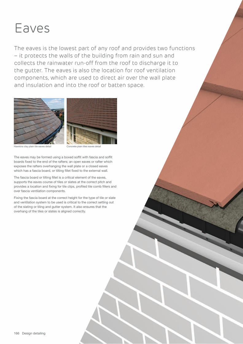
EavesThe eaves is the lowest part of any roof and provides two functions– it protects the walls of the building from rain and sun and collects the rainwater run-off from the roof to discharge it to the gutter. The eaves is also the location for roof ventilationcomponents, which are used to direct air over the wall plate and insulation and into the roof or batten space.
166 Design detailing
The eaves may be formed using a boxed soffit with fascia and soffitboards fixed to the end of the rafters; an open eaves or rafter whichexposes the rafters overhanging the wall plate or a closed eaveswhich has a fascia board, or tilting fillet fixed to the external wall.
The fascia board or tilting fillet is a critical element of the eaves,supports the eaves course of tiles or slates at the correct pitch andprovides a location and fixing for tile clips, profiled tile comb fillers andover fascia ventilation components.
Fixing the fascia board at the correct height for the type of tile or slateand ventilation system to be used is critical to the correct setting outof the slating or tiling and gutter system. It also ensures that theoverhang of the tiles or slates is aligned correctly.
Concrete plain tiles eaves detailHawkins clay plain tile eaves detail

For advice, literature and samples Tel 01283 722588 or visit marleyeternit.co.uk 167

168 Design detailing
Selected eaves details
eaves vent systemsThe Universal eaves ventilation systems shown on pages 168-171 are suitable for all tiles and slates.
> eaves ventilation to satisfy 10mm or 25mm conditions
> eaves to ridge ventilation for pitches of 12.5°-55°
> continuous rafter roll compresses insulation to allow free air passage (use two rolls to compress deep insulation)
> strip ventilator has discreet ventilation grille and is nailed tofascia or timber fillet
> suitable with or without soffit board
> use comb filler strip with deep profiled tiles
> mechanically fix all tiles at eaves
10mm eaves ventwith plain tiles (cold roof)

For advice, literature and samples Tel 01283 722588 or visit marleyeternit.co.uk 169
Underlay
Felt support tray
Tilting fillet
Mendip
10mm over fasciastrip ventilator
325mm strip of UV durable underlay dressed into gutter
Continuous rafterroll (2 No.)
Underlay
Edgemere
CounterbattensMin. 75mmheadlap
Tilting fillet
25mm over fasciastrip ventilator
Battens at max.345mm gauge
325mm strip of UV durable underlay dressed into gutter
Edgemere eaves clip
Felt support tray
Continuous rafterroll (2 No.)
10mm eaves vent with interlocking tiles (cold roof)
25mm eaves vent with interlocking slates (warm roof)

170 Design detailing
Selected eaves details
Underlay
50mm
Fibre cement slates
Tilting fillet
25mm over fasciastrip ventilator
Battens
325mm strip of UV durable underlay dressed into gutter
Felt support tray
Continuous rafter roll (2 No.)
fibre cement 25mm eaves vent with fibrecement slates (warm roof)
Melodie clay interlocking pantile
10mm over fasciastrip ventilator
Continuous rafterroll (2 No.)
Headlap range 92-126mm
Battens at 314-348mm flexible gauge
Tiling fillet
25mm eaves ventwith Melodie interlocking claytiles (cold roof)
For advice, literature and samples Tel 01283 722588 or visit marleyeternit.co.uk 171
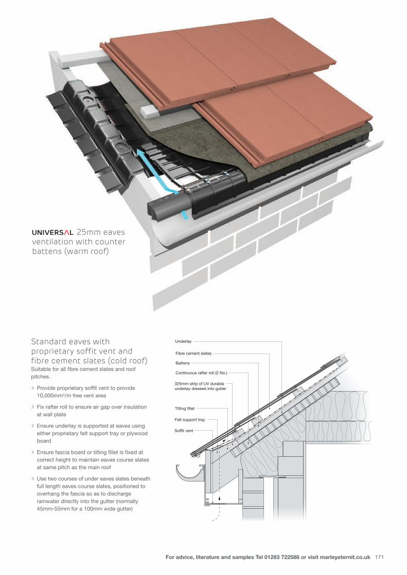
25mm eavesventilation with counterbattens (warm roof)
Standard eaves withproprietary soffit vent andfibre cement slates (cold roof)Suitable for all fibre cement slates and roofpitches.
> Provide proprietary soffit vent to provide 10,000mm2/m free vent area
> Fix rafter roll to ensure air gap over insulation at wall plate
> Ensure underlay is supported at eaves using either proprietary felt support tray or plywood board
> Ensure fascia board or tilting fillet is fixed at correct height to maintain eaves course slates at same pitch as the main roof
> Use two courses of under eaves slates beneathfull length eaves course slates, positioned to overhang the fascia so as to discharge rainwater directly into the gutter (normally 45mm-55mm for a 100mm wide gutter)
Underlay
Fibre cement slates
Tilting fillet
Battens
325mm strip of UV durable underlay dressed into gutter
Felt support tray
Continuous rafter roll (2 No.)
Soffit vent

Verges
172 Design detailing
The verge is one of the most exposed parts of a roofand is prone to wind-driven rain and wind vortices,which can affect the integrity of the tiles or slates.The choice of verge construction is often dictatedby the type of tile or slate being used.
Flat interlocking tiles and slates are more likely to experience rainwaterbeing driven over the edge of the verge in exposed conditions. It is,therefore, good practice to select a bargeboard construction for thissituation, which will help to prevent water staining of the gable wall. Insevere conditions, such as exposed parts of Scotland and Wales, itmay even be desirable to extend the gable wall above the height ofthe roof to create an abutment with secret gutter, in order to giveadded protection.
The verge occurs at the roof’s junction with the gable end wall and isnormally at right angles to the eaves and ridge. Verge constructionnormally takes the following form – the external wall construction isbuilt up to a level with the top of the rafters to allow the roof coveringto oversail the wall with a soffit and sloping bargeboard.
Mortar bedding of the verge tiles or slates onto a fibre cement or tileundercloak is the traditional method of weatherproofing the verge of a roof but must always be mechanically fixed.
Dry fix cloak verge tiles and units are available to suit a range ofMarley Eternit tiles and slates and offer a low maintenance and secure method of fixing the verge tiles and slates.
It is important to consider the overhang of the roof covering at the verge, as this is often controlled by the horizontal setting out of the tiles or slates, but should not exceed 50mm.
Mendip interlocking tile dry verge detailFibre cement slates verge detail

For advice, literature and samples Tel 01283 722588 or visit marleyeternit.co.uk 173

174 Design detailing
Verge clip
Mortar bedding
Anglia
Tiling batten
Underlay
Fibre cement undercloak
Bedded verge withinterlocking tilesSuitable for clay and concrete plain tiles,interlocking tiles and slates and fibre cement slates.
> ensure undercloak does not tilt towards gable
> verge overhang should be 38mm-50mm
> mechanically fix all verge tiles in accordance with BS 5534
> fit verge clips to both left hand and right hand verges where required
Slate verge trimSuitable for fibre cement slates.
> suitable for dry verges with or without bargeboard
> not suitable for raking verges
> when used with timber sarking, ensure outer structure is brought up to underside of tiling battens
> extend battens to edge of bargeboard or brickwork
Rafter
Batten
Underlaycarried acrossflying rafter
Flyingrafter
Verge trim nailed to battens
Fibre cement slates
Selected verge details

For advice, literature and samples Tel 01283 722588 or visit marleyeternit.co.uk 175
Mortar bedding Plain tile-and-a-half tile
Plain tile
Plain tileundercloaklaid face down Tiling batten
Underlay
Rafter
Bedded verge with plain tilesSuitable for all plain tiles.
> form using tile and tile-and-a-half tiles in alternate courses
> use undercloak of either fibre cement laid with slope away from outer wall or plain tiles laid face down and overhanging wall
> verge overhang to be 38mm-50mm
> fully nail all tiles at verge where possible
> mortar bedding to comply with tensile board strength in BS 5534
Dry verge with interlocking tilesSuitable for Double Roman, Ludlow Major,Mendip, Modern, Duo Modern and Wessexinterlocking tiles. (A separate verge system isalso available for Edgemere, Duo Edgemereand Riven Edgemere).
> maximum pitch for duo-pitch and mono-pitch roof is 55° (when used with steep-pitch dry ridge system)
> suitable for verges with or without bargeboard
> when using sarking, ensure outer wall or bargeboard is brought up to underside of tiling battens
> finish tiling battens 50mm beyond gable brickwork or bargeboard to a true line
> lay roof tiles with overhang of 45mm for using tile shunt and/or half tiles as required
> mechanically fix all verge tiles in accordance with BS 5534
> at ridge/mono-ridge fit PVCu ridge end cap

176 Design detailing
Underlay carriedacross cavity
Mendip verge unit
Rafter
BattenMendipMendip half tileInterlocking cloak verge with interlocking tilesSuitable for Mendip and Double Romaninterlocking tiles.
> maximum pitch for duo-pitch and mono-pitch roofs is 45° (55° if top cloak verge tiles are mitred)
> not suitable for raking verges
> suitable for tile laps 75mm-115mm (305mm-345mm gauge)
> Use tile shunt and half tiles to reduce overhang to minimum
> for pitches over 30°, where no fixing for ends of tiling battens, use double course of battens secured over at least two rafters
> fix each cloak verge tile with special fixings supplied
> finish ridge with block end ridge tiles (duo or mono)
Selected verge details

For advice, literature and samples Tel 01283 722588 or visit marleyeternit.co.uk 177
Plain tile cloak verge (concrete)Suitable for Plain tiles.
> maximum pitch for duo-pitch and mono-pitch roofs is 55° (mitre top cloak verge tiles if required)
> not suitable for raking verges
> finish tiling battens flush with edge of bargeboard or brickwork
> complete verge using cloak verge tiles in alternate courses with tile and a half tiles
> fix all tiles with 2 no. 38mm x 2.65mm aluminium nails
> at apex of roof/verge fit block end ridge tile
Underlay carriedacross cavity
Rafter
Modern cloakverge unit Batten Modern half tile Modern
Interlocking cloak verge withModern interlocking tilesSuitable for Modern interlocking tiles.
> maximum pitch for duo-pitch and mono-pitch roofs is 45° (55° if top cloak verge tiles are mitred)
> not suitable for raking verges
> suitable for tile laps 75mm-115mm (305mm-345mm gauge)
> use tile shunt and half tiles to reduce overhang to minimum
> for pitches over 30°, where no fixing for ends of tiling battens, use double course of battens secured over at least two rafters
> fix each cloak verge tile with special fixings supplied
> finish ridge with block end ridge tiles (duo or mono)

Hips
178 Design detailing
Table 5: Fibre cement ridge and hip fittingsDesign pitch Pitch of Effective pitch Recommendedmain roof ridge at hip pitch of duo-pitch
cappings hip cappings20° 20° 14° 15°
22.5° 25° 15° 15°
25° 25° 17.5° 20°
27.5° 30° 19° 20°
30° 30° 20° 20°
35° 35° 24° 25°
40° 40° 27° 30°
45° 45° 30° 30°
50° 50° 33° 35°
55° 55° 35° 35°Table 5 assumes that pitches on each side are identical and that slopes intersect at right angles on plan.
A hip occurs where two roof slopes of any pitch meet,forming a junction which water runs away from.Commonly, the two roof slopes will intersect at rightangles on plan, but other plan angles are also common,as in a hexagonal or octagonal shaped roof design. A pyramid roof will have four hips meeting at an apex.
Unlike a ridge, a hip can never be horizontal, as it normally starts atthe eaves and finishes at the ridge. Some hips start and finish at anyjunction in the roof construction where two roof slopes meet. If therafter pitch is different on either side of the hip, the hip line will vary onplan and may cause water to run up the hip, instead of away from it.This should be avoided wherever possible.
The junction of the tiles between the two roof slopes can beweathered using purpose-made hip tiles or cappings, which arenormally of a flatter angle than their ridge counterparts. Alternatively,the junction can be weathered using metal soakers under close-mitredtiles or slates. This provides a neat, clean, sharp edge at the hipjunction and is often used for interlocking and fibre cement slates.
Fibre cement slate detail using HipFast Plain tile detail with granny bonnet hip tiles

BS 5534 and mortar hipsUnder the British Standard, the use ofmortar as a sole means of fixing roof tilesand fittings is insufficient.
Not only should careful consideration begiven to the creation of a suitable roofmortar through the correct sand andcement mix, but tiles or fittings beddedwith this mortar must also beaccompanied by a mechanical fix.
ME Solution: Mortarbedded security ridgeand hip kits Where mortar bedding is required,Marley Eternit now offers a mortarbedded security ridge and hip kit,providing installers with enoughmechanical fixings to secure up to sixmetres of each. In addition, clips formechanically fixing small tile cuts at the hip and valley are also available. See page 150.
Table 6: Relationship of roof pitch to internal angle of hipKnown Internal angles of hip tileroof pitch Plain tile roof Slate roof20-25° – 135°
30° 145° 135°
35° 145° 125°
37.5° 140° 125°
40° 135° 115°
42.5° 135° 115°
45° 130° 115°
47.5° 127° 115°
50° 125° 105°
52.5° 120° –
55° 120° –
57.5° 115° –
60° 115° –
Known internal angle Slate roof pitchof ridge/hip tile at hip
75° –
90° –
105° 50°
115° 40-50°
125° 30-40°
135° 20-30°
For advice, literature and samples Tel 01283 722588 or visit marleyeternit.co.uk 179

180 Design detailing
Close mitred hip with fibre cement slatesSuitable for fibre cement slates and plain tiles
> for pitches over 30° (slates) and 50° (plain tiles)*
> use double width slate or tile/slate and a half for raking cuts
> insert Code 3 lead soakers at every course
> fix each raking cut slate or tile with three nails (plus two rivets for slates)
* Where the roof pitch is below 30º or the site is exposed,fibre cement ridge/hip fittings should be used (see page 76).
Selected hip details

For advice, literature and samples Tel 01283 722588 or visit marleyeternit.co.uk 181
Underlay
Battens at max 100mm gauge
Plain tile Granny bonnet hip tileGranny bonnet hip with clay plain tilesSuitable for all plain tiles.
> maximum rafter pitch 60° (clay) and 50° (concrete)
> use on hips with plan angle of 90° and equal pitches on adjacent roof slopes
> fix to hip batten using 70mm x 3.35mm aluminium nail
> bed and point with 3:1 sand/cement mortar to BS 5534
> complete hip at ridge or top abutment with lead saddle
Third round hip tile
Hip union
GRP support tray
Hip clamp and screw
HipFast roll
MendipHip batten brackets
HipFast systemwith interlocking tilesSuitable for all interlocking tiles and planangles and where the pitch either side of thehip varies by a maximum 5°.
Provides additional ventilation to the roof voidwhen a 5mm gap is provided in the underlayand is used in conjunction with either eavesor ridge ventilation systems, or vent tiles.
> maximum rafter pitch (45° Ashmore; 50° Edgemere/Duo Edgemere, Modern/Duo Modern, Ludlow Plus; 55° Ludlow Major and Double Roman; 60° Plain, Mendip, Wessex, Anglia, Melodie, Maxima and fibre cement slates
> provides additional ventilation to the roof void when a 5mm gap in the underlay is used in conjunction with either eaves or ridge ventilated systems or ventilation tiles
> use one or two thicknesses of 50mm x 25mm batten to fit batten brackets
> use block end hip tile at eaves
> mechanically fixes each hip tile via hip unions and clamps
> complete hip at ridge with soaker flashing

182 Design detailing
Fixing block screwedto hip rafter
High profile hip batten section
Batten
Mendip
Tingle clip
Third round hip tile
Hip union
Foam strip
Underlay lapped over hip
Dry hip system Suitable for all tiles and slates using thirdround or Modern hip tiles.
> maximum rafter pitch 55° (45° when using dry ridge)
> suitable for hips with plan angle of 90° and where the pitch either side of the hip varies by a maximum 5°
> secures raking cut tiles or interlocking slates using head and tail clips
> secure PVCu batten section to hip tree or batten using screws and expansion blocks
> mechanically fixes each hip tile to PVCu batten section via hip unions
> complete hip at ridge apex with dry hip apex cap
Underlay
Battens at max 100mm gauge
Plain tile Arris hip tile
Arris hip with clay plain tilesSuitable for all plain tiles.
> maximum rafter pitch 50° (clay) and 40° (concrete)
> use on hips with plan angle of 90° and equal pitches on adjacent roof slopes
> fix to hip batten using 65mm x 3.35mm aluminium nail
> bed top of tiles with 3:1 sand/cement mortar to BS 5534
> complete hip at ridge or top abutment with lead saddle
Selected hip details
For advice, literature and samples Tel 01283 722588 or visit marleyeternit.co.uk 183
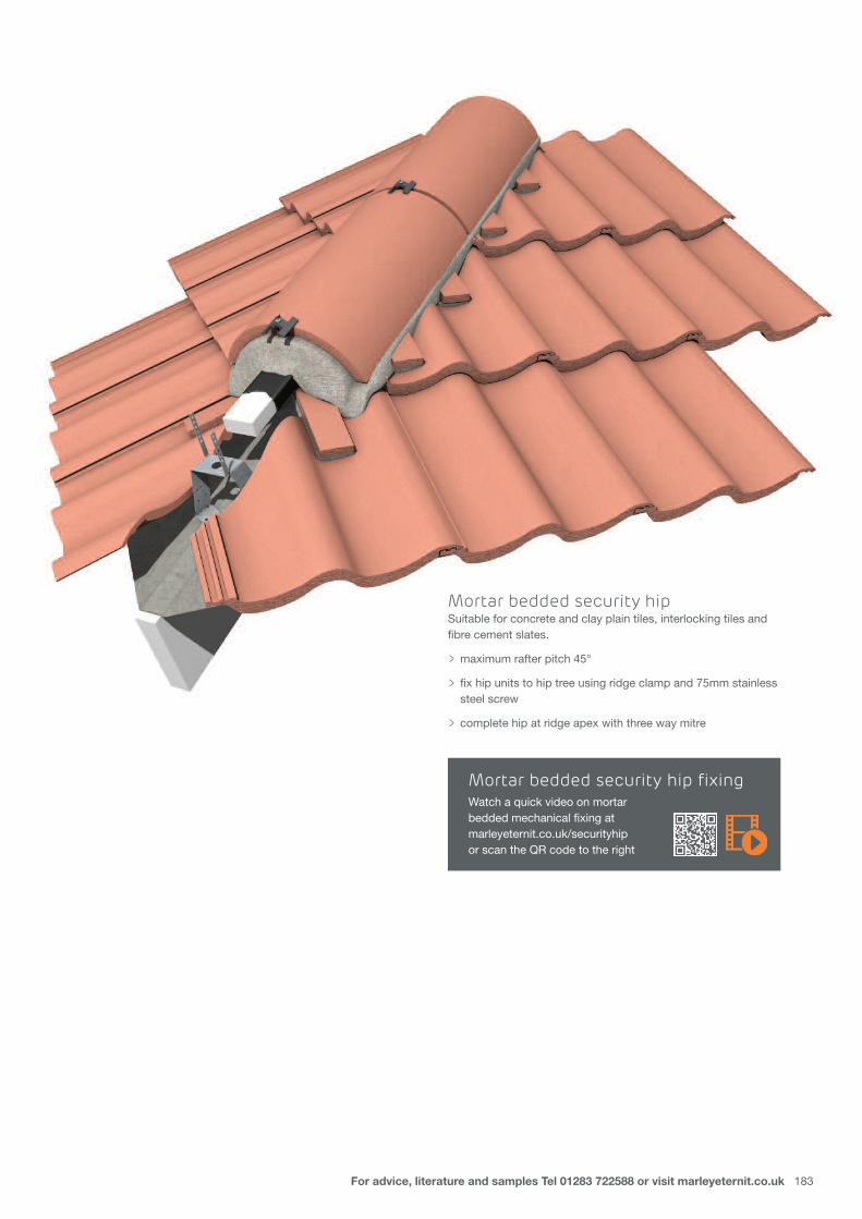
Mortar bedded security hipSuitable for concrete and clay plain tiles, interlocking tiles and fibre cement slates.
> maximum rafter pitch 45°
> fix hip units to hip tree using ridge clamp and 75mm stainless steel screw
> complete hip at ridge apex with three way mitre
Mortar bedded security hip fixingWatch a quick video on mortar bedded mechanical fixing at marleyeternit.co.uk/securityhip or scan the QR code to the right
Valleys
184 Design detailing
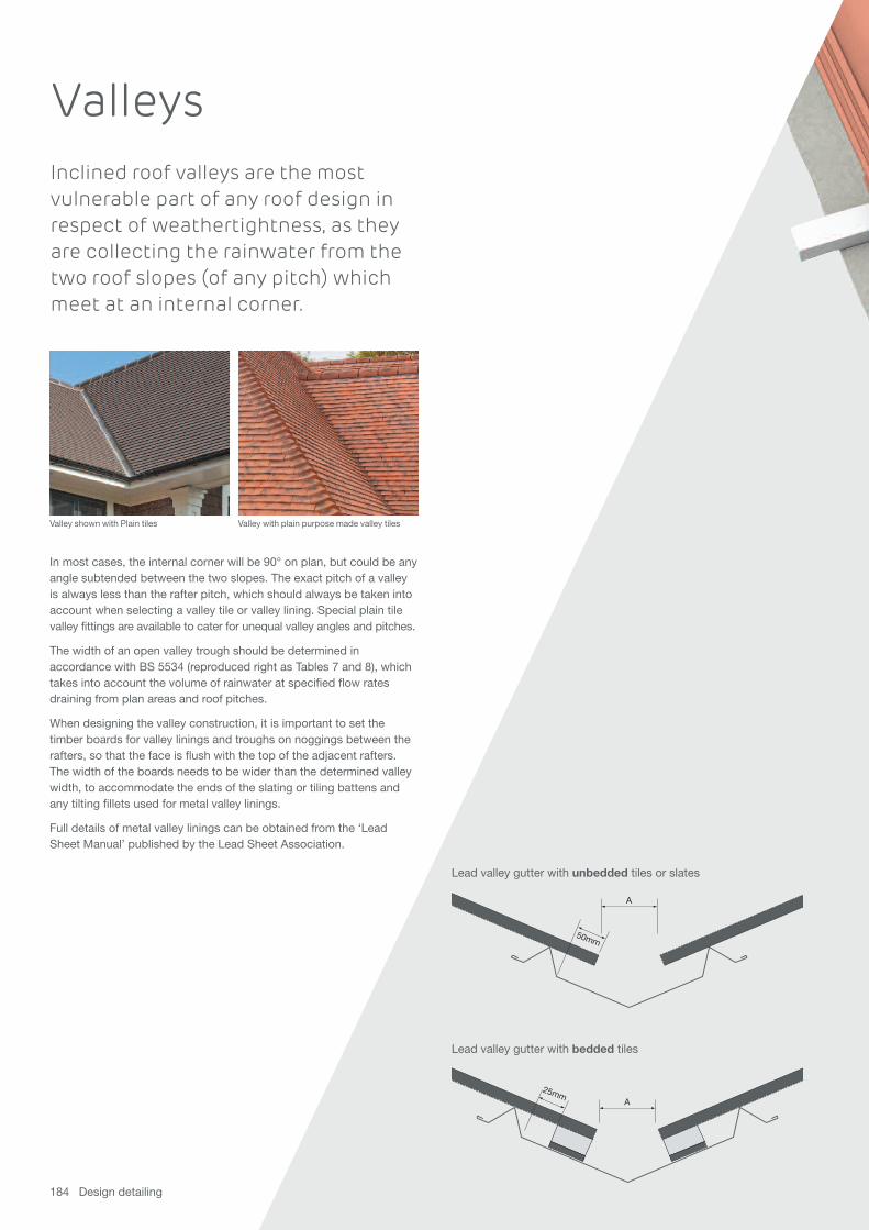
50mm
A
A
25mm
Lead valley gutter with unbedded tiles or slates
Lead valley gutter with bedded tiles
Inclined roof valleys are the most vulnerable part of any roof design inrespect of weathertightness, as theyare collecting the rainwater from thetwo roof slopes (of any pitch) whichmeet at an internal corner.
In most cases, the internal corner will be 90° on plan, but could be anyangle subtended between the two slopes. The exact pitch of a valleyis always less than the rafter pitch, which should always be taken intoaccount when selecting a valley tile or valley lining. Special plain tilevalley fittings are available to cater for unequal valley angles and pitches.
The width of an open valley trough should be determined inaccordance with BS 5534 (reproduced right as Tables 7 and 8), whichtakes into account the volume of rainwater at specified flow ratesdraining from plan areas and roof pitches.
When designing the valley construction, it is important to set thetimber boards for valley linings and troughs on noggings between therafters, so that the face is flush with the top of the adjacent rafters.The width of the boards needs to be wider than the determined valleywidth, to accommodate the ends of the slating or tiling battens andany tilting fillets used for metal valley linings.
Full details of metal valley linings can be obtained from the ‘LeadSheet Manual’ published by the Lead Sheet Association.
Valley with plain purpose made valley tilesValley shown with Plain tiles

For advice, literature and samples Tel 01283 722588 or visit marleyeternit.co.uk 185
Table 7: Min. widths of valley gutter* for different roof pitches/plan areasDesign rainfall rate 225mm/h 150mm/h 75mm/h
Roof area to 25m2 and less over 25m2 up to 25m2 and less over 25m2 up to 25m2 and less over 25m2 up tobe drained on plan† 100m2 on plan‡ on plan† 100m2 on plan‡ on plan† 100m2 on plan‡
12.5-17° roof pitch 150mm 250mm 125mm 200mm 125mm 150mm
17.5-22° roof pitch 125mm 200mm 125mm 150mm 100mm 125mm
22.5-29° roof pitch 100mm 150mm 100mm 125mm 100mm 100mm
30-34° roof pitch 100mm 125mm 100mm 100mm 100mm 100mm
>35° roof pitch 100mm 100mm 100mm 100mm 100mm 100mm * Dimension A (see diagrams, left) is measured as a horizontal distance between the tiles or slates in millimetres.† The rafter lengths are equal to or less than 5m on plan.‡ refer to BS 5534 6.1.1
Table 8: Min. widths of lead to line valley gutters for different roof pitches/plan areas
Design rainfall rate
Roof area to 25m2 and less over 25m2 up tobe drained on plan† 100m2 on plan‡
12.5-17° roof pitch 550mm 650mm
17.5-22° roof pitch 525mm 600mm
22.5-29° roof pitch 500mm 550mm
30-34° roof pitch 500mm 525mm
>35° roof pitch 500mm 500mmThe performance and minimum design of valley pitch for proprietary valley products should beobtained from the Technical Advisory Service. The design rainfall rates and risk categories aresummarised in BS EN 12056.
For lead valleys, see also Volume 1 of the Lead Sheet Manual, published by the Lead SheetAssociation.
Table 9: Relationship of roof pitch to valley angleKnown roof pitch Plain tile roof internal angles of valley12.5-20° –
20-25° –
30° 150°
35° 150°
37.5° 145°
40° 140°
42.5° 140°
45° 135°
50° 130°
52.5° 125°
55° 125°
186 Design detailing
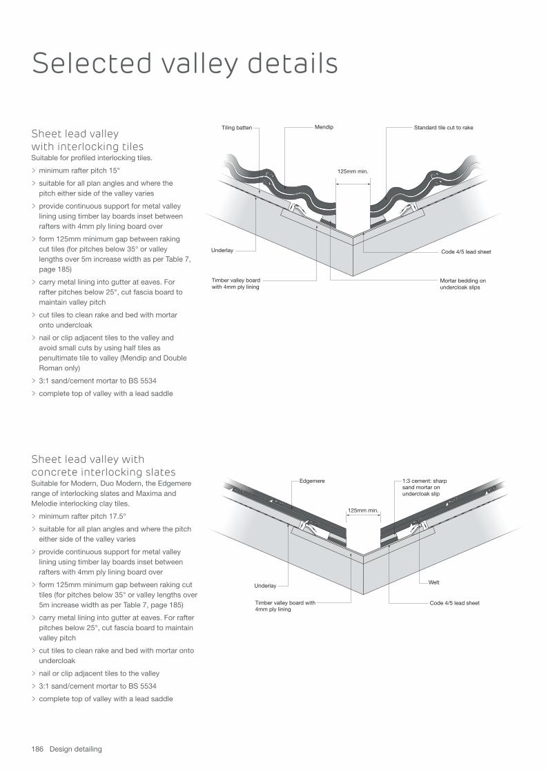
Sheet lead valley with concrete interlocking slatesSuitable for Modern, Duo Modern, the Edgemererange of interlocking slates and Maxima andMelodie interlocking clay tiles.
> minimum rafter pitch 17.5°
> suitable for all plan angles and where the pitch either side of the valley varies
> provide continuous support for metal valley lining using timber lay boards inset between rafters with 4mm ply lining board over
> form 125mm minimum gap between raking cut tiles (for pitches below 35° or valley lengths over 5m increase width as per Table 7, page 185)
> carry metal lining into gutter at eaves. For rafter pitches below 25°, cut fascia board to maintain valley pitch
> cut tiles to clean rake and bed with mortar onto undercloak
> nail or clip adjacent tiles to the valley
> 3:1 sand/cement mortar to BS 5534
> complete top of valley with a lead saddle
Sheet lead valley with interlocking tilesSuitable for profiled interlocking tiles.
> minimum rafter pitch 15°
> suitable for all plan angles and where the pitch either side of the valley varies
> provide continuous support for metal valley lining using timber lay boards inset between rafters with 4mm ply lining board over
> form 125mm minimum gap between raking cut tiles (for pitches below 35° or valley lengths over 5m increase width as per Table 7, page 185)
> carry metal lining into gutter at eaves. For rafter pitches below 25°, cut fascia board to maintain valley pitch
> cut tiles to clean rake and bed with mortar onto undercloak
> nail or clip adjacent tiles to the valley and avoid small cuts by using half tiles as penultimate tile to valley (Mendip and Double Roman only)
> 3:1 sand/cement mortar to BS 5534
> complete top of valley with a lead saddle
Timber valley board with4mm ply lining
Underlay
Code 4/5 lead sheet
1:3 cement: sharpsand mortar onundercloak slip
Welt
125mm min.
Edgemere
Standard tile cut to rake
Underlay
Mortar bedding onundercloak slips
Code 4/5 lead sheet
Timber valley boardwith 4mm ply lining
125mm min.
Tiling batten Mendip
Selected valley details

For advice, literature and samples Tel 01283 722588 or visit marleyeternit.co.uk 187
GRP dry valley with interlocking tilesSuitable for all profiled large format concrete interlocking tiles (Ludlow Major, Duo Modern, Modern, the Edgemere range, Duo Edgemere, Wessex, Mendip,Double Roman, Maxima and Melodie).
> minimum rafter pitch 17.5°, maximum 60°
> maximum valley length 8m
> suitable for all plan angles and where the pitch either side of the valley varies by a maximum of 20°
> provide continuous support for valley trough using 19mm timber ply boards inset between rafters or 6mm continuous ply boards laid over rafters
> tightly butt tiles or slates to central upstand of valley units to prevent ingress of birds or vermin
> provide metal apron at foot of valley and dress into gutter at eaves. For rafter pitches below 25° cut fascia board to maintain valley pitch
> nail or clip adjacent tiles to the valley and avoid small cuts by using half tiles as penultimate tile to valley (Mendip, Double Roman and Modern only). Fix smaller cut tiles with clips provided
> complete top of valley with a lead saddle
Clay plain tiles with purpose made valley tilesSuitable for all clay plain tiles.
> suitable for roof pitches of 30-50°. A range of valley tiles are available to suit roof pitch
> suitable for a plan angle of 90° only and equal pitches either side of the valley
> provide continuous support for valley tile using timber lay boards of battens inset between rafters
> use tile-and-a-half tiles adjacent to valley tile to avoid small cuts
> complete top of valley with a lead saddle
Battens at max 345mm gauge Slate cut to angle of valley
Edgemere slate
Underlay
Rafter
19mm (min) timber valley board
Low profile dry valley trough
Tiling batten

Tiling batten
Underlay
Code 4/5 lead sheet
Timber valley board with 4mm ply lining
125mmmin.
Slate cut to angle of valley
Plain valley tiles
Tiling batten UnderlayTimber valley boardwith 4mm ply lining
Plain tile
188 Design detailing
Selected valley details
Sheet metal valley with fibre cement slatesSuitable for all double lap fibre cement slates.
> minimum rafter pitch 22.5°*
> suitable for all plan angles and where the pitch either side of the valley varies
> provide continuous support for metal valley lining using timber lay boards inset between rafters with 4mm ply lining board over
> form 125mm minimum gap between raking cut slates (for pitches below 35° or valley lengths over 5m increase width as per Table 7, page 185)
> carry metal lining into gutter at eaves
> use double slates to minimise small cuts
> fix each raking cut slate or tile with three nails (plus two rivets for slates)
> complete top of valley with a lead saddle* subject to special circumstances
Plain tile
Tiling batten
Underlay
Code 4/5 lead sheet
Timber valley board with 4mm ply lining
125mmmin.
Sheet metal valley with plain tilesSuitable for concrete or clay plain tiles.
> minimum rafter pitch 35°
> suitable for all plan angles and where the pitch either side of the valley varies
> provide continuous support for metal valley lining using timber lay boards inset between rafters with 4mm ply lining board over
> form 125mm minimum gap between raking cut tiles
> carry metal lining into gutter at eaves
> use tile-and-a-half tiles to minimise small cut tiles
> nail all adjacent tiles to the valley
> complete top of valley with a lead saddle
Valley tile with plain tilesSuitable for concrete plain tiles.
> maximum rafter pitch 50°
> suitable for a plan angle of 90° only and equal pitches either side of the valley
> provide continuous support for valley tile using timber lay boards or battens inset between rafters
> use tile-and-a-half tiles adjacent to valley tile to avoid small cuts
> complete top of valley with a lead saddle

For advice, literature and samples Tel 01283 722588 or visit marleyeternit.co.uk 189
GRP slate dry valley with fibre cement slatesSuitable for all double lap fibre cement slates.
> minimum rafter pitch 22.5°, maximum 45°
> suitable for all plan angles and where the pitch either side of the valley varies by a maximum of 15°
> provide continuous support for valley trough using 19mm ply timber lay boards inset between rafters or 6mm continuous ply boards laid over rafters
> form 125mm minimum gap between raking cut slates (for pitches below 35° or valley lengths over 5m contact the Technical Advisory Service)
> use tail rivets and nails to secure rafting cut fibre cement slates
> complete top of valley with a lead saddle

Ridges
190 Design detailing
The ridge is the most exposed part of a roof, and it is therefore important that it is well protected by theuse of ridge tiles or cappings suited to the pitch of theroof and the type of roof tile or slate. All ridge units –even if mortared – should be mechanically fixed.
A ridge occurs at the highest point of the roof and is normally parallelwith the eaves. Duo pitch ridges occur when two roof slopes meet at their upper edge. Where the top of one roof meets a vertical wall, it forms either a mono-pitch roof or a top abutment.
A duo pitch ridge can be formed using ridge components with orwithout mortar bedding. All ridge units – even when mortared –should be mechanically fixed in accordance with BS 5534. Dry fixridge systems enable the complete ridge assembly to be mechanicallyfixed and also provide ventilation to the apex of the roof space.
The ridge may also be used to terminate ventilation ducts and gas flue pipes via the use of purpose-made vent ridge terminals. Specialprecautions are necessary to prevent noxious gases and fumes from entering the roof space or via adjacent roof windows.
The junction between ridges, hips, valleys and abutments must besuitably mitred and weathered using a metal saddle or flashing unit.
Acme clay plain tile ridge detailEdgemere interlocking slates with Ridge Fast
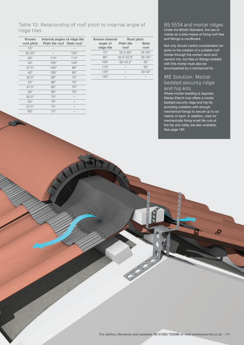
BS 5534 and mortar ridgesUnder the British Standard, the use ofmortar as a sole means of fixing roof tilesand fittings is insufficient.
Not only should careful consideration begiven to the creation of a suitable roofmortar through the correct sand andcement mix, but tiles or fittings beddedwith this mortar must also beaccompanied by a mechanical fix.
ME Solution: Mortarbedded security ridgeand hip kits Where mortar bedding is required,Marley Eternit now offers a mortarbedded security ridge and hip kit,providing installers with enoughmechanical fixings to secure up to sixmetres of each. In addition, clips formechanically fixing small tile cuts at the hip and valley are also available. See page 150.
Table 10: Relationship of roof pitch to internal angle ofridge tiles
Known Internal angles of ridge tileroof pitch Plain tile roof Slate roof
15° – –
20-25° – 125°
30° 115° 115°
35° 105° 105°
37.5° 105° 90°
40° 105° 90°
42.5° 90° 75°
45° 90° 75°
47.5° 90° 75°
50° 90° 75°
52.5° 75° –
55° 75° –
57.5° 75° –
60° 75° –
Known internal Roof pitchangle of Plain tile Slateridge tile roof roof
75° 52.5-60° 45-50°
90° 42.5-52.5° 35-45°
105° 30-42.5° 35°
115° – 30°
125° – 20-30°
135° – –
For advice, literature and samples Tel 01283 722588 or visit marleyeternit.co.uk 191

192 Design detailing
Selected ridge details
Fibre cement slates
Underlay
Sela wood screw Duo pitched ridge capping
Battens
Fibre cement slate ridge rollVentilated Ridge Roll for use with fibrecement slates and ridgesSuitable for use with all fibre cement slateswith duo-pitch ridges (15° to 60°)
> provides 5000mm2/m continuous ventilation to the roof apex
> ensure 5mm clear gap between top edges of underlay at the roof apex
> lay top course slates in normal manner, allowing for additional timber batten to screw fix ridge capping
> lay ridge roll centrally along ridge apex, overlapping lengths by 100mm
> fit ridge cappings above ridge roll and fix to ridge fix battens using 60mm x 6.3mm self-sealing wood screws
> apply 6mm dia. butyl strip across socket of ridge capping
> complete ridge ends with stop end ridge units

For advice, literature and samples Tel 01283 722588 or visit marleyeternit.co.uk 193
Ventilated dry ridge with fibre cement slates Suitable for all fibre cement slates.
> maximum rafter pitch 45° (55° using steep pitch ridge batten)
> provides 5,000mm2/m free vent area at ridge apex
> ensure gap is provided in roof underlay to vent roof void
> hook fix top course slates
> mechanically fix each Modern ridge tile
> complete ridge with dry ridge end cap or Modern block end ridge tile
Modern ridge tile
Underlay cut to allow ventilation
Ridge union
Ventilated filler unit
Cut top course slates
Stainlesssteel hook
Fibrecementslate
Batten section nailedto each rafter
RidgeFast ventilated dry ridgesystem with interlocking tilesSuitable for all tiles and slates using standard ridges.
> maximum rafter pitch (45° interlocking slates and Ashmore; 50° Edgemere range, Modern/Duo Modern, Ludlow Plus; 55° Ludlow Major and Double Roman; 60° Plain, Mendip, Wessex and Anglia)
> provides 5,000mm2/m free vent area at ridge apex
> ensure gap is provided in roof underlay to vent roof void
> use one or two thicknesses of 50mm x 25mm batten to fit batten brackets
> mechanically fix all top course tiles
> use block end ridge tile or PVC ridge end cap at ridge end

194 Design detailing
Ridge vent terminal with dry ridge andinterlocking tilesSuitable for all concrete tiles and slates (using Modern and Segmentalridge tiles).
> maximum rafter pitch 45° (55° using steep pitch ridge batten)
> provides 9,500mm2/m free vent area at ridge apex
> locate between two adjacent rafters and 600mm from any flue outlet
> use plumbers accessory pack for connection to mechanical extract system
> ensure all ductwork is adequately supported
Selected ridge details
Underlay cut back to provide 5mm-10mm air gap
Segmental mono-ridge tile
Dry ridge batten section
Ventilated filler unit
Mono-ridge union
Ludlow Major
50 x 10g s/s screw fixing
Ventilated dry fix mono-ridgewith interlocking tilesSuitable for all concrete plain, interlocking tiles and slates and fibre cement slates (using concrete Segmental mono ridge tiles).
> maximum rafter pitch 45° (55° using steep pitch ridge batten)
> provides 5,000mm2/m free vent area at ridge apex
> ensure gap is provided in roof underlay to vent roof void
> fix all top course tiles and slates
> mechanically fix each ridge tile via ridge unions
> complete ridge with Segmental mono ridge block end tile (LH and RH) or Segmental mono ridge end cap

For advice, literature and samples Tel 01283 722588 or visit marleyeternit.co.uk 195
Mortar bedded security ridgeSuitable for mortar bedded ridges
> security ridges are available for all clay or concrete angle, half round, third round, hog’s back, capped angular, baby and decorative ridge tiles
> maximum rafter pitch 60°
> fix ridge units to ridge batten using ridge clamp and 75mm stainless steel screw
> mechanically fixes ridge tile in line with BS 5534 fixing guidelines
Mortar bedded security ridge fixingWatch a quick video on mortar bedded mechanical fixing at marleyeternit.co.uk/securityridge or scan the QR code to the right

Abutments
196 Design detailing
An abutment occurs where the edge of the roof slope meets awall that rises above it. Normally, on a side abutment, this is atright angles to the eaves or ridge, but may be at an angle, inwhich case, it is referred to as a raking abutment. It is best practice to ensure that rainwater runs away from a side abutment, but where this is not possible, an inclined valleyshould be created which is designed to cater for the water flow.
Side abutmentsThese should be formed with a suitable flashing, usually lead, whichcan provide the required weather protection and accommodate anythermal movement that may occur.
Cavity trays and d.p.c’s in the masonry wall should be designed sothat they allow any flashings to be inserted below them, therebymaintaining their weatherproofing function.
Side abutments using flat tiles and slates are particularly vulnerable towind driven rain, and should therefore be designed with secret guttersand/or soakers and cover flashings, which provide suitable protection.
Full details of side abutment flashings can be obtained from the ‘Lead Sheet Manual’ published by the Lead Sheet Association.
Top abutmentsA top abutment occurs where the top of a roof slope meets a wall that rises above it.
Normally, this will be horizontal but if not, it is referred to as a raking side abutment. It is best practice to ensure that rainwater runs away from a top abutment.
Top abutments should be formed with a suitable flashing, usually lead. The length of the flashing material dressed over the top course tiles is determined by the pitch of the roof tile or slate and the exposure of the site, and can vary from 150-390mm (see LSA recommendations).
Top abutments may also be continuously ventilated using proprietary ventilation systems which incorporate the flashing material with ventilation apertures and fit above the top course of roof tiles or slates.
Abutment using Mendip interlocking tilesAbutment using Edgemere interlocking slates

Table 11: Length of top abutment flashing over tile or slatePitch 15-17° 17.5-19.5° 20-22° 22.5-27° 27.5-34.5° 35-90°
Length 390mm 350mm 300mm 250mm 200mm 150mm
For advice, literature and samples Tel 01283 722588 or visit marleyeternit.co.uk 197

Side abutment with clay plain tilesSuitable for all concrete and clay plain tiles.
> bring tiles as close to abutment as possible
> use Code 3 lead soakers and Code 4 lead cover flashing
198 Design detailing
Batten
Tile clip Underlay
Code 4 lead
Lead support strip
Edgemere ventilatedfiller unit
Edgemere
Dry ridgebatten section
Underlay cut back5mm min. to provideventilation
Min.75mm
Code 3 lead soakers
Plain tile-and-a-half tile
Clay plain tile
Underlay
D.P.C.
Code 4 step flashing
Min. 75mm
100mmBatten
Rafter
Top abutment ventilation withconcrete interlocking slatesSuitable for all concrete tiles and slates and fibre cement slates.
> maximum rafter pitch 45° (55° using steep pitch batten section)
> provides 5,000mm2/lin.m ventilation
> ensure air passage from roof void is not obstructed
> mechanically fix all top course tiles
> use minimum 1.5m length of lead flashing with 150mm side laps
Selected abutment details

For advice, literature and samples Tel 01283 722588 or visit marleyeternit.co.uk 199
Side abutment with fibrecement slatesSuitable for all fibre cement slates.
> bring slates as close to abutment as possible
> use Code 4 lead step and cover flashing and Code 3 lead soakers (minimum width 175mm)
> fix all slates adjacent to abutment

200 Design detailing
Top abutment ventilation with concrete interlocking tilesSuitable for all concrete tiles and slates and fibre cement slates.
> maximum rafter pitch 45° (55° using steep pitch batten section)
> provides 5,000mm2/lin.m ventilation
> ensure air passage from roof void is not obstructed
> mechanically fix all top course tiles
> use minimum 1.5m length of lead flashing with 150mm side laps
Selected abutment details

For advice, literature and samples Tel 01283 722588 or visit marleyeternit.co.uk 201
Code 4 lead
Lead support strip
Double lap slatesventilated filler unit
Dry ridgebatten section
Min.75mm
Cavity tray
Fibre cement slate
Stainlesssteel hook
Top abutment ventilationwith fibre cement slatesSuitable for all fibre cement slates.
> maximum rafter pitch 45° (55°usingsteep pitch batten section)
> provides 5,000mm2/lin.m ventilation
> ensure air passage from roof void is not obstructed
> maintain minimum 75mm upstand of flashing
> use minimum 1.5m length of lead flashing with 150mm side laps
Side abutment with interlocking tilesSuitable for all concrete and clay interlocking tiles. A secret gutter detail is required for flatinterlocking tiles and slates.
> bring tiles as close to abutment as possible
> use Code 4 lead step and cover flashing dressed over tiles by 150mm minimum
> secure edge of flashing with copper clip
> fix all tiles adjacent to abutment
Code 4 lead stepand cover flashing
Mendip
150mm minCode 4 lead step flashing
D.P.C

Roof slopes
202 Design detailing
The roof slope offers the designer an opportunity to allow the passage of light and ventilation to theinterior of the building. This can be achieved bynumerous details in the form of dormers androoflights or ventilation terminals and pipes.
Roof lights should be located well away from chimneys or flues, roofvalleys and hips, or other details, which might interrupt the effectivedrainage of the roof slope. Care should be taken to ensure that thecorrect flashings are used for the type of roof covering selected.
Ventilation terminals located in the roof slope should be spaced evenlyin accordance with the free vent area of the terminal, and therequirements of the Building Regulations. Terminals used to extractnoxious gases, such as from soil pipes, must be positioned well awayfrom openings in the building such as roof windows or dormers, incompliance with the Building Regulations.
Pipes that project through the roof slating or tiling should be suitablyweathered with a lead flashing, which fits tightly around the pipe anddresses over adjacent tiles or slates.
Interruptions and changes of pitch sometimes incorporate a change in rafter pitch, either as a sprocket where the upper rafter pitch issteeper than the lower, or as a mansard where the upper rafter pitch is shallower than the lower rafter pitch. Whatever the detail,consideration must be given to detailing the junctions with anappropriate flashing material or a purpose-made fitting. Where the junction of two different roof coverings on a common roof slope occurs over a party wall, a suitable detail is required that maintains the weatherproofing of the roof assembly and provides the required level of fire resistance. There are several options to cater for this detail, ranging from proprietary bonding gutters to purpose-made gutters and soakers formed from lead. Full details of all lead flashings and soakers can be obtained by reference to the ‘Lead Sheet Manual’ published by the Lead Sheet Association.
Roof slopes that require access for the purpose of maintenance or repair should be designed to accommodate safe working equipment or platforms that comply with the Construction Design and Management Regulations and Health and Safety at Work regulations.
Mendip interlocking tile roof slopeHawkins clay plain tile roof slopes

For advice, literature and samples Tel 01283 722588 or visit marleyeternit.co.uk 203

204 Design detailing
Underlay cut &nailed to batten
Battens at max345mm gauge
PVCu soaker tray
Min. 50mmair gap
Underlay
Edgemereventilation slate
Grille
Edgemere
Tile vent terminal withinterlocking slates (warm roof)Suitable for all concrete interlocking tiles andslates.
> locate clear of rafters
> use soaker tray to weather hole in underlay for spigot
> locate at 1.3-1.5m centres for 5,000mm2/lin.m ventilation and 565-765mm centres for 10,000mm2/lin.m ventilation
For mechanical extract/soil pipe termination
> use flexible pipe for connection to 110mm dia. pipework as termination to mechanical extract or soil vent pipe
> do not use as exhaust for hot flue gases
> when used as extract for soil vent pipes, keep minimum 900mm above any openinginto building within 3m of vent terminal
Lower tray
Grille
Baffles
Soil adaptor/extractor(optional)
Water drainage channels
Soaker tray
Fibre cement slate
In-line fibre cement slate vent terminal(soil pipe mechanical extraction)Suitable for all fibre cement slates.
• locate clear of rafters
• use soaker tray to weather hole in underlay for spigot
• locate at 2.0m centres for 5,000mm2/lin.m ventilation and 1.0m centres for 10,000mm2/lin.m ventilation
• use slate vent adaptor and flexible pipe for connection to 110mm dia. pipework as termination to mechanical extract or soil vent pipe
• do not use as exhaust for hot flue gases
• when used as extract for soil vent pipes, keep minimum 900mm above any opening into building within 3m of vent terminal
Selected roof slope details

For advice, literature and samples Tel 01283 722588 or visit marleyeternit.co.uk 205
In-line vent terminal with clayplain tiles (cold roof)Suitable for all clay plain tiles.
> locate clear of rafters
> use soaker tray to weather hole in underlay for spigot
> locate at 1.5m centres for 5,000mm2/lin.m ventilation and 0.75mm centres for 10,000mm2/lin.m ventilation
For mechanical extract/soil pipe termination> use tile vent adaptor for connection to 110mm
dia. pipework as termination to mechanical extract or soil vent pipe
> do not use as exhaust for hot flue gases
> when used as extract for soil vent pipes, keep minimum 900mm above any openinginto building within 3m of vent terminal
Pure Roofing Part B 15a_Layout 1 17/09/2015 16:31 Page 205

206 Design detailing
150mm min.
Underlay taken over lead
Modern
Code 4 lead
Layboard andtimber fillet
Alternative position of tile to conceal flashing
Change of pitch with interlocking tilesSuitable for all concrete and clay interlocking tiles.
> provide timber layboard and fillet for lead flashing
> maintain continuous lap of underlay at junction of two pitches
> extend upper course of tiles over lead to conceal flashing
> allow minimum 150mm lap of flashing onto lower course of tiles
Selected roof slope details
tile vent terminal with concreteinterlocking tilesSuitable for all large format and ‘15 x 9’ interlocking tiles includingMaxima clay interlocking tiles.
> locate clear of rafters
> use soaker tray to weather hole in underlay
> locate at 3.0m centres for 5,000mm2/lin.m ventilation and 1.5m centres for 10,000mm2/lin.m ventilation
> suitable for roof space ventilation and mechanical extract and soil vent pipe
> Use flexible pipe for connection to 110mm dia. pipework as termination to mechanical extract or soil vent pipe
> Do not use as exhaust for hot flue gases
> When used as extract for soil vent pipes, keep minimum 900mm above any opening into building within 3m of vent terminal

For advice, literature and samples Tel 01283 722588 or visit marleyeternit.co.uk 207
Change of pitch with fibre cement slatesSuitable for all fibre cement slates.
> detail lower edge of upper slope as at eaves
> provide timber fillet for lead flashing to dress over top course slates
> maintain continuous lap of underlay at junction of two pitches
> allow minimum 150mm lap of Code 4 lead flashing onto top course of slates
> fix edge of flashing with copper clips at 300-500mm centres
150mm min.
Code 4 lead
Underlay taken over lead
Timber fillet
Lead welt
Fibre cement slate
Mansard with fibre cementslatesSuitable for all fibre cement slates.
> detail lower edge of upper slope as at eaves
> ensure upper eaves course overhangs lower slope by 50mm
> provide timber fillet for lead flashing
> use Code 4 lead cover flashing dressed 150mm minimum onto top course slates
> fix edge of flashing with copper clips at 300mm-500mm centres
150mm. min
Underlay taken over lead
Timber fillet
Code 4 lead
Fibre cement slate

Special details
208 Design detailing
Due to their small format, most slates and plain tilesare well suited to forming a variety of special detailsranging from the more traditional ‘Winchester’ and‘Sussex’ gable ends to the more complex curvedroof geometries associated with eyebrow andcurved roofs, mansard and roof slope junctions.
In addition, the designer now has a wide choice of rigid under-tile or slate systems, which have advantages in providing better thermalefficiency and weathertightness of the roof system, but require special consideration when detailing the tile or slate covering.
Pages 210-213 show a small selection of special details using Marley Eternit products and accessories and are offered for guidance only. Other similar details may prove equally satisfactory.
In all cases, the design team should satisfy themselves that the detailsfinally selected are appropriate to the specific application, andadequate for the site and its degree of exposure.
Please note that these pages are intended for the use of designers,and therefore do not include full fixing information. Those requiringguidance on fixing tiles and slates should refer to our range of sitework and fixing guides.
Acme double camber clay plain tiles (SmoothBrindle) with eyebrow detail
Vertical slating with fibre cement slates(hook fixed)

For advice, literature and samples Tel 01283 722588 or visit marleyeternit.co.uk 209

210 Design detailing
Vertical slating with fibrecement slatesFibre cement slates can be fixed to verticalsurfaces and provide an attractive andweatherproof cladding on both timber frameand masonry constructions. The followingguidance notes apply to this detail:
> use counterbattens over masonry construction (38mm x 25mm minimum) to reduce direct fixing. Special masonry fixings may be required.
> slate-and-a-half should be used in alternate courses at internal and external corners and adjacent to openings.
> use Code 3 lead soakers to weather internal and external corners.
> fix slates by two nails and one rivet, and slate-and-a-half by three nails and two rivets.
> Code 4 lead cover flashings should be used above and below openings in accordance with Lead Sheet Association recommendations
Selected special details
VertigoMarley Eternit fibre cement Vertigo panels arelightweight, weather andtemperature resistant and create beautiful,distinctive and elegantvertical cladding solutionsfor a full range of buildingtypes. For more on Vertigo,please see pages 80-87.

For advice, literature and samples Tel 01283 722588 or visit marleyeternit.co.uk 211
Code 4 lead flashingat head
Eaves/top tile
38mm x 25mm tilingbattens at 115mm gauge
Approved underlay
Eaves/top tile
Code 4 lead flashingdressed over timbertilting fillet
Code 4 lead apron flashingfixed beneath sill anddressed over eaves/top tileby 100mm min.
Tile to form soffit
Exposed edge of tilesto be pointed incement mortar
65mmminimum
Plain tile
Vertical tiling with plain tilesPlain tiling is an excellent, weatherproof and attractive cladding to the vertical walls of any building. Feature and ornamental tiles may also be used with normal plain tiles to create decorative patterns.
> use counterbattens over masonry construction (38mm x 25mm minimum) to reduce direct fixing. Special masonry fixings may be required
> ensure tiling details do not interfere with the opening of windows and doors
> lead flashings and soakers should be used around openings in accordance with Lead Sheet Association details
> use double course of tiles at eaves, by laying first course of eaves/tops tiles with course of full tiles over
> at top of wall or under a sill, use a course of eaves/tops tile laid over a course of full tiles. Dress a Code 4 lead cover flashing over by 100mm
> use internal and external angle tiles at all 90° corners. Purpose made 135° angle tiles are also available. For other angles, close mitre tiles and use Code 3 lead soakers
> all tiles should be twice nailed
Winchester cut with plain tilesThis gable end detail may be used for both concrete and clay plaintiles, and avoids the use of small triangular pieces of tile by providinga secure fixing of a tile-and-a-half against the rake of the gable.
> best suited for roof pitches of 40° and above
> fix batten parallel with rake of verge and level with vertical tiling battens
> use tile-and-a-half at end of each course and cut to rake (all tiles should be of uniform cut)
> cut adjacent tile to raking cut tile-and-a-half
> use Code 3 lead soakers (200mm x 200mm) where side laps are less than 55mm
> at apex, use a tile-and-a-half turned through 45° and cut to shape

212 Design detailing
Roofing practice in Scotland includes the use oftimber sarking and counterbattens. With the growingtrend towards the use of insulated boards as a rigidsarking in habitable roofs, many of the standard roofdetails will be affected by the increase in thicknessof the layer of the roof assembly. Of particular concern is the design of the counterbatten and batten fixings, which often requirespecial proprietary fixings capable of providing adequate withdrawal resistance through theinsulation and into the rafter (see Annex B of BS 5534).
Underlay
Mendip
Tilting fillet
25mm over fasciastrip ventilator
Counterbattens
Battens
325mm strip of BS 747 type 5U or equivalent UV durable underlay dressed into gutter
Felt support tray
Continuous rafterroll (2 No.)
Rigid sarking
25mm ventilatedeaves detail with profiledinterlocking tilesSuitable for all tiles and slates.
> use where insulation follows the line of the rafter
> maximum rafter pitch is 55°
> minimum pitch is 15° (dependent on tile profile)
> timber sarking and counterbattens should terminate just below the first course batten and directly behind the top edge of the underlay support tray
> suitable for use with or without soffit
> ensure fascia board is to correct height so as not to cause eaves course tiles to either tilt or droop. Height above rafter will vary with rafter pitch and allowance should be made for the thickness of the sarking and counterbattens
> use additional rafter trays to bridge extra thickness of insulation so as to maintain ventilation path
> mechanically fix all eaves course tiles and use a comb filler strip with deeply profiled tiles

For advice, literature and samples Tel 01283 722588 or visit marleyeternit.co.uk 213
50mm
Ridge fixing battenRoll top ridge
Fibre cement ventilated ridge roll
Fibre cement slate50mm x 6.3mmself-sealingwoodscrew
Underlay carriedacross cavity
Rafter
Counterbatten
Sarking
Batten Modern tileUniversal verge unit
Hidden fixing nail
Ventilated dry ridge with fibre cement slatesSuitable for use with all fibre cement slateswith duo-pitch ridges (20° to 60°) and mono-pitch ridges (20° to 45°).
> can be used with fibre cement duo pitch, roll top and mono-ridge ridge cappings
> provides 5000mm2/m continuous ventilation to the roof apex
> ensure 5mm clear gap between top edges of sarking and underlay at the roof apex
> lay top course slates in normal manner, allowing for additional timber batten to screw fix ridge capping
> lay ridge roll centrally along ridge apex, overlapping lengths by 100mm
> fit ridge cappings above ridge roll and fix to ridge fix battens using 60mm x 6.3mm self-sealing wood screws
> apply 6mm dia. butyl strip across socket of ridge capping
> complete ridge ends with stop end ridge units
dry verge detailwith interlocking slatesSuitable for all interlocking concrete tiles. A separate verge unit is available forEdgemere and Duo Edgemere.
> maximum rafter pitch 45° (55° when usedwith Steep Pitch Dry Ridge)
> top of outer and inner leaves of masonry should be level with top of counterbattens to allow battens to extend across
> allow for extra thickness of any external render or roughcast to outer leaf of masonry. Certain types of finish will require a timber board to facilitate a level surface for the dry verge units
> extend tiling battens 45mm over edge of render or roughcast
> nail each verge unit to ends of tiling battens
> finish apex with PVC ridge end cap
> mechanically fix all verge tiles