hilscher universal driver - opcturkeyopcturkey.com/uploads/manuals/hilscher-universal-manual.pdf ·...
TRANSCRIPT

Hilscher Universal Driver
© 2016 PTC Inc. All Rights Reserved.

Hilscher Universal Driver
TableofContentsHilscher Universal Driver 1
Table of Contents 2
Hilscher Universal Driver 4
Overview 4
External Dependencies 4
Channel Setup 5
Board Selection 5
Slave Board Configuration 5
SyCon Database 22
Options 23
I/O Data References 23
Addressing Type 25
Bit Reference Tags 25
8 Bit Data Expansion 27
16 bit Data Expansion 29
32 bit Data Expansion 31
Device Setup 33
Device Type 33
Data Types Description 34
Address Descriptions 35
Process Image Address Descriptions 35
IEC Address Descriptions 39
Automatic Tag Database Generation 45
Error Descriptions 48
Error Codes 49
Address Validation 51
Missing address 52
Device address '<address>' contains a syntax error 52
Address <address>' is out of range for the specified device or register 52
Data Type '<type>' is not valid for device address '<address>' 52
Device address '<address>' is Read Only 53
Array size is out of range for address '<address>' 53
Array Support is not available for the specified address: '<address>' 53
Driver ErrorMessages 53
Unable to load '<dll>' 53
Unable to import from '<dll>' 54
www.kepware.com
2
Hilscher Universal Driver
DevOpenDriver () failed with error code '<code>' 54
Memory allocation error 54
Device StatusMessages 54
Device '<device name>' is not responding 55
Unable to read device info data in area '<area>'. Board '<board>' returned Error Code '<code>' 56
Unable to read '<block size>' device info bytes in area '<area>'. Board '<board>' returned ErrorCode '<code>' 56
Unable to read task state data in task '<task num>'. Board '<board>' returned Error Code '<code>'57
Unable to read '<block size>' task state bytes in task '<task num>'. Board '<board>' returned ErrorCode '<code>' 57
Unable to read tag '<address>' from device '<device>'. Board '<board>' returned Error Code'<code>' 57
Unable to read '<block size>' bytes starting at '<address>' from device '<device>'. Board'<board>' returned Error Code '<code>' 58
Unable to write to tag '<address>' from device '<device>'. Board '<board>' returned Error Code'<code>' 58
Unable to read tag '<name>': msg.b=<command>, msg.device_adr=<Device ID>... 58
Unable to read '<block size>' message bytes: msg.b=<command>, msg.device_adr=<Device ID>... 59
Unable to read tag '<address>' from device '<device>'. Board '<board>' returned DPMDiagnostics [Global Bits='<Global Bits>', Node='<Remote Address>', Code='<Error Event>'] 59
Unable to read '<block size>' bytes starting at '<address>' from device '<device>'. Board'<board>' returned DPM Diagnostics [Global Bits='<Global Bits>', Node='<Remote Address>',Code='<Error Event>'] 59
Unable to write to tag '<address>' from device '<device>'. Board '<board>' returned DPMDiagnostics [Global Bits='<Global Bits>', Node='<Remote Address>', Code='<Error Event>'] 60
Unable to read tag '<address>' from device '<device>'. Board '<board>' returned DNMDiagnostics [Global Bits='<Global Bits>', Node='<Device Address>', Code='<Error Event>'] 60
Unable to read '<block size>' bytes starting at '<address>' from device '<device>'. Board'<board>' returned DNM Diagnostics [Global Bits='<Global Bits>', Node='<Device Address>',Code='<Error Event>'] 60
Unable to write to tag '<address>' from device '<device>'. Board '<board>' returned DNMDiagnostics [Global Bits='<Global Bits>', Node='<Device Address>', Code='<Error Event>'] 61
Automatic Tag DatabaseGenerationMessages 61
The file is not a valid Sycon database or may be corrupt 61
Auto tag database generation cannot be performed while the driver is processing tags 61
Board Type for Board '<board number>' does not match the actual board installed. Verify BoardType and/or Board Selection 62
Board Type for Board '<board number> does not match the Slave Type for one or more Slavesconfigured. Delete or edit Slaves accordingly 62
'dbm32.dll' is not loaded and is required for auto tag generation. Verify SyCon is installed 62
Index 63
www.kepware.com
3

Hilscher Universal Driver
Hilscher Universal DriverHelp version 1.021
CONTENTS
OverviewWhat is the Hilscher Universal Driver?
Channel SetupHow do I configure a channel for use with this driver?
Device SetupHow do I configure a device for use with this driver?
Data Types DescriptionWhat data types does this driver support?
Address DescriptionsHow do I address a data location from a master/slave device?
Automatic Tag Database GenerationHow can I easily configure tags for the Hilscher Universal Driver?
Error DescriptionsWhat error messages does the Hilscher Universal Driver produce?
OverviewThe Hilscher Universal Driver provides an easy and reliable way to connect Hilscher Universal devices toOPC client applications, including HMI, SCADA, Historian, MES, ERP and countless custom applications. It isintended for use with Hilscher Communications Interface (CIF) cards. I/O and diagnostic information isavailable through the OPC server. The CIF cards currently supported are DeviceNet Master/Slave andProfibus DP Master/Slave.
External DependenciesThis driver has external dependencies. It requires that SyCon (Hilscher's System Configuration Software)and the correct PCI interface card (CIF 50 models) be installed on the same machine as the OPC server.
www.kepware.com
4
Hilscher Universal Driver
Channel SetupA channel represents the SyCon Configuration Database, which includes the board assignment anddevice/module definitions. The device/module definitions are imported from the configuration file. For moreinformation, refer to SyCon Database Import.
Select a link from the list below for information on a specific aspect of Channel Setup.
Board SelectionHow do I select the board number and bus type over which communications will occur?
Slave Board ConfigurationHow do I configure a local Hilscher Slave board? How do I configure the server to communicate directly withthe local Slave board?
SyCon Database ImportHow do I specify the location of the SyCon Configuration Database?
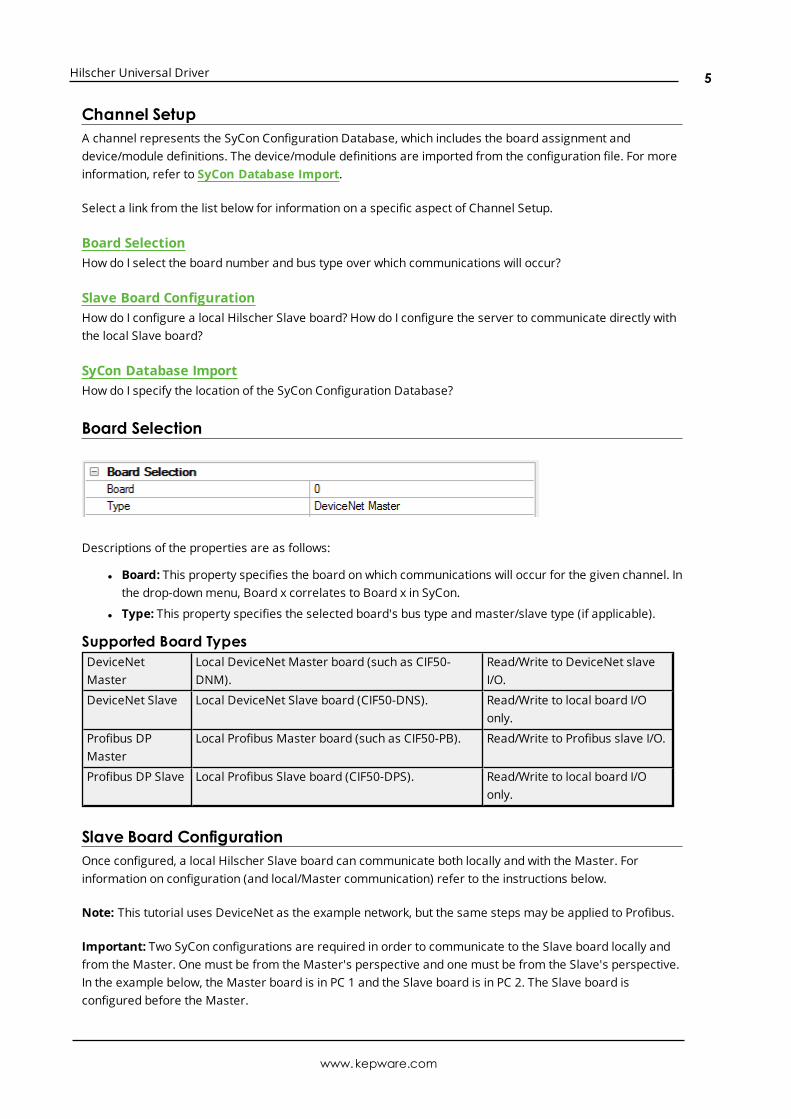
Board Selection
Descriptions of the properties are as follows:
l Board: This property specifies the board on which communications will occur for the given channel. Inthe drop-downmenu, Board x correlates to Board x in SyCon.
l Type: This property specifies the selected board's bus type andmaster/slave type (if applicable).
Supported Board TypesDeviceNetMaster
Local DeviceNet Master board (such as CIF50-DNM).
Read/Write to DeviceNet slaveI/O.
DeviceNet Slave Local DeviceNet Slave board (CIF50-DNS). Read/Write to local board I/Oonly.
Profibus DPMaster
Local Profibus Master board (such as CIF50-PB). Read/Write to Profibus slave I/O.
Profibus DP Slave Local Profibus Slave board (CIF50-DPS). Read/Write to local board I/Oonly.
Slave Board ConfigurationOnce configured, a local Hilscher Slave board can communicate both locally and with the Master. Forinformation on configuration (and local/Master communication) refer to the instructions below.
Note: This tutorial uses DeviceNet as the example network, but the same steps may be applied to Profibus.
Important: Two SyCon configurations are required in order to communicate to the Slave board locally andfrom the Master. One must be from the Master's perspective and one must be from the Slave's perspective.In the example below, the Master board is in PC 1 and the Slave board is in PC 2. The Slave board isconfigured before the Master.
www.kepware.com
5

Hilscher Universal Driver
PC 2 SyCon Configuration (Slave)
1. To start, open an empty SyCon project and insert a "dummy" Master. The master chosen is irrelevantsince the configuration will be downloaded to the Slave.
Note:When prompted, do not assign the hardware if the Master board is in the same machine as theSlave board.
www.kepware.com
6

Hilscher Universal Driver
2. Next, insert the Slave and select a unique MAC ID.
3. Assign the MAC ID to the local Slave board.
4. Then, configure the I/O.
www.kepware.com
7

Hilscher Universal Driver
Note: The network should appear as shown below.
5. Save and then download the configuration to the Slave board by clicking Online | Download. This isthe configuration that will be imported into the server later.
www.kepware.com
8
Hilscher Universal Driver
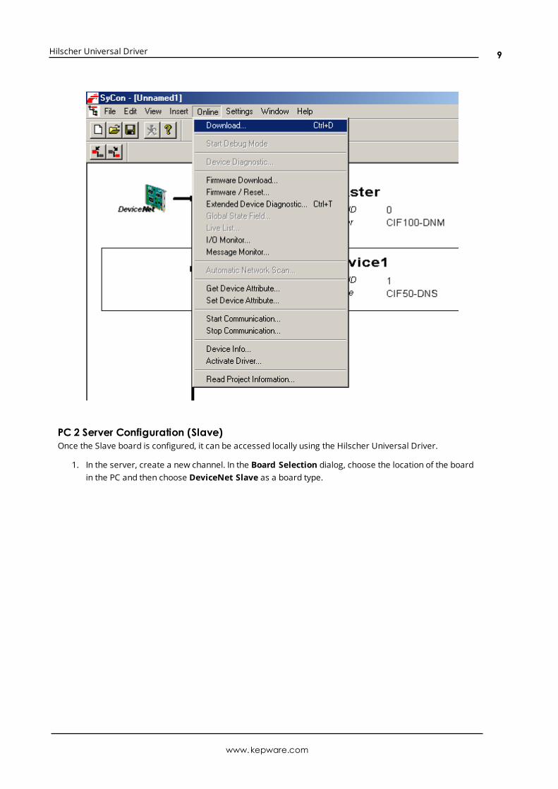
PC 2 Server Configuration (Slave)Once the Slave board is configured, it can be accessed locally using the Hilscher Universal Driver.
1. In the server, create a new channel. In the Board Selection dialog, choose the location of the boardin the PC and then choose DeviceNet Slave as a board type.
www.kepware.com
9

Hilscher Universal Driver
www.kepware.com
10

Hilscher Universal Driver
2. Set Expanded SyCon Tag Import to Enable.
3. In the New Channel Wizard summary, enter the Tag Imprt File by clicking on the ellipsis andbrowsing for the SyCon configuration file previously created.
www.kepware.com
11

Hilscher Universal Driver
4. Next, create a new device and set the Device ID to the MAC ID of the Slave board. In this example, itis 1.
www.kepware.com
12

Hilscher Universal Driver
5. Automatically generate the tags for the Slave. To do so, click Channel Properties | SyConDatabase.
6. Click on the “Synchronize tags” link to generate the tags.
www.kepware.com
13

Hilscher Universal Driver
7. Note: The image below displays the tags created for the configured Slave board.
PC 1 SyCon Configuration (Master)Assume that the Slave board in PC 2 is configured for communications and access it from the DeviceNetMaster in PC 1. A Master board configuration is required.
1. First, open an empty SyCon project and insert the Master.
www.kepware.com
14

Hilscher Universal Driver
2. Assign it to the local Master board.
3. Next, insert the Slave. Alternatively, perform Automatic Network Configuration.
4. Assign the MAC ID chosen in Step 2 of PC 2 SyCon Configuration (Slave).
Note:Do not assign the hardware when prompted if the Master board is in the same machine as theSlave board.
5. Configure the I/O. Its values must match the configured I/O in the Slave SyCon configuration createdearlier.
www.kepware.com
15

Hilscher Universal Driver
6. If desired, insert the Bar Code Reader Slave. This is not required. The resulting network shouldappear as displayed below.
www.kepware.com
16

Hilscher Universal Driver
\
www.kepware.com
17

Hilscher Universal Driver
7. Save and then download the configuration to the Master board by clicking Online | Download.
PC 1 Server Configuration (Master)Now that the Master board is configured, the Slave board can be accessed remotely using the HilscherUniversal Driver.
1. In the server, create a new channel. In the Board Selection dialog, choose the location of the boardin the PC. For board type, select DeviceNet Master.
www.kepware.com
18

Hilscher Universal Driver
www.kepware.com
19

Hilscher Universal Driver
2. Set Expanded SyCon Tag Import to Enable.
3. In the the New Channel Wizard summary, summary, enter the Tag Imprt File by clicking on the ellipsisand browsing for the SyCon configuration file s previously created.
4. Next, create a new device and set the Device ID to the MAC ID of the Slave board in PC 2. In thisexample, it is 1. Then, create a new device and set the Device ID to the MAC ID of the Bar CodeReader. In this example, it is 2.
www.kepware.com
20

Hilscher Universal Driver
5. Automatically generate the tags for the Slaves. To do so, click Channel Properties | SyConDatabase. Click the Synchronize tags link to generate the tags.
6. The image below displays the tags created for the Slave board in PC 2.
www.kepware.com
21
Hilscher Universal Driver
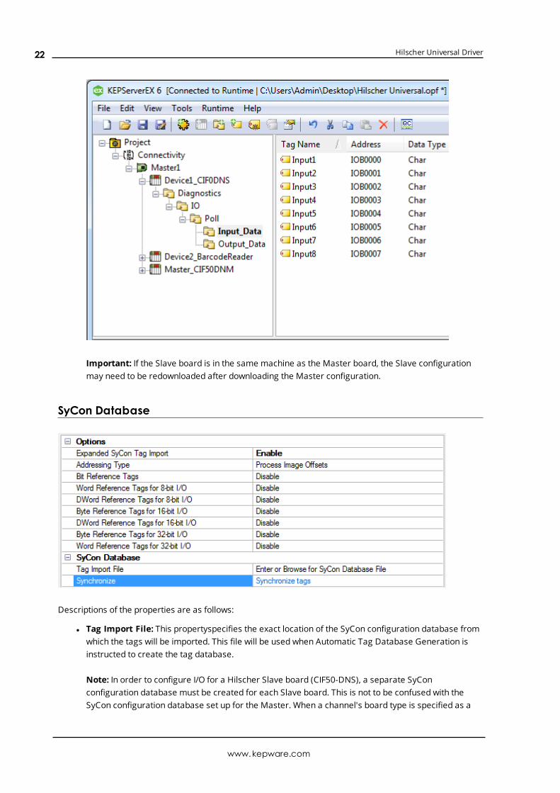
Important: If the Slave board is in the same machine as the Master board, the Slave configurationmay need to be redownloaded after downloading the Master configuration.
SyCon Database
Descriptions of the properties are as follows:
l Tag Import File: This propertyspecifies the exact location of the SyCon configuration database fromwhich the tags will be imported. This file will be used when Automatic Tag Database Generation isinstructed to create the tag database.
Note: In order to configure I/O for a Hilscher Slave board (CIF50-DNS), a separate SyConconfiguration database must be created for each Slave board. This is not to be confused with theSyCon configuration database set up for the Master. When a channel's board type is specified as a
www.kepware.com
22

Hilscher Universal Driver
Slave-type, the SyCon Database specified must correspond specifically to this Slave. For moreinformation, refer to Slave Board Configuration.
l Synchronize: clicking “Synchronize tags” will generate tags for the channel.
Supported DatabasesProfibus-DP Database Extension: .pbDeviceNet Database Extension: .dn
See Also: Automatic Tag Database Generation
OptionsFor more information on a specific property or topic, select one of the links below.
l I/O Data References
l Addressing Type
l Bit Reference Tags
l 8-Bit Data Expansion
l 16-Bit Data Expansion
l 32-Bit Data Expansion
I/O Data ReferencesExpanded SyCon Tag ImportWhen disabled, this option only imports the I/O symbolic names that are configured in SyCon. Tags will begenerated under the following folder:
IO\\<bus dependant module path>\\
When enabled, this option imports the I/O Symbolic Names configured in SyCon and also generatesalternative references for each symbolic name. These alternative references (or Expansion Tags) providedifferent ways of looking at the same piece of data. Tags will be generated under the following folders:
IO\\<bus dependant module path>\\PIIO\\<bus dependant module path>\\IEC
Note:Depending on the Addressing Type, tags may be generated to both of these folders. For moreinformation, refer to Addressing Type.
www.kepware.com
23

Hilscher Universal Driver
ExamplesSyConByte Addressing should be assumed. For more information on Byte andWord addressing modes, refer toAddress Descriptions. Details are as follows:
l Configured I/O Module:Word Array, QW, Length 4, Offset 0.
l Symbolic Names:Default is Output001, Offset 0, Word.
OPC ServerFor Expansion Tags, 16 bit Module Data / Byte References should be assumed. The following tags will begenerated in the OPC server under the specific options:
l Import only SyCon I/O Tags:Output001, Offset 0, Word.
l Expanded SyCon Tag Import:Output001, Offset 0, Word; Output001_B0_QB, Offset 0, Byte;Output001_B1_QB, Offset 1, Byte.
Symbolic Names and Expansion Tags DifferencesSyCon creates default symbolic names based on the Configured I/O. Users can create additional symbolicnames (such as Bit, Word, DWord and String tags) within SyCon. Each SyCon symbolic name is imported asan individual tag in the OPC server. Expansion tags are an expansion of the symbolic name tags imported,regardless of whether or not the symbolic name tag is an expansion of the Configured I/O.
ExamplesSyConByte addressing should be assumed.
l Configured I/O Module: Byte Array, IB, Length 10, Offset 0.
l Symbolic Names:Default: Input001, Offset 0, Byte.
Note: These were created for the module MyWordTag, Offset 0, Word.
OPC ServerFor Expansion Tags, Generate Bit References should be assumed. The following tags will be generated in theOPC server under the specific options:
l Import only SyCon I/O Tags: Input001, Offset 0, Byte; MyWordTag, Offset 0, Word.
l Import and Expand SyCon I/O Tags:Input001, Offset 0, ByteInput001_IX_00, Offset 0, Bit 0Input001_IX_01, Offset 0, Bit 1...Input001_IX_07, Offset 0, Bit 7MyWordTag, Offset 0, WordMyWordTag_B0_IX_00, Offset 0, Bit 0...MyWordTag_B0_IX_07, Offset 0, Bit 7MyWordTag_B1_IX_00, Offset 1, Bit 0...MyWordTag_B1_IX_07, Offset 0, Bit 7
Note: The example above shows how all symbolic name tags are expanded based on the chosen properties.Only bit references were generated additionally.
www.kepware.com
24

Hilscher Universal Driver
Important:Using Expansion Tags should eliminate the need to create additional symbolic names in SyCon.The exception to this is Strings, since these are not included in the Expansion Settings.
Addressing TypeThere are two types of I/O addresses supported in the Hilscher Universal Driver: Process Image OffsetAddressing and IEC Addressing. Descriptions are as follows:
l Process Image Offset Addressing: Address mnemonic and offsets are based on the physical offsetinto the Master's Process Image Memory Map (I/O Data). Addresses are always byte-based,regardless of the addressing mode selected in SyCon's Master Settings.
IO\\<bus dependant module path>\\PI
Note: Expansion Tags will be generated in a tag group labeled "PI". All tag addresses in this groupwill be based on Process Image Addressing.
l IEC Addressing: Address mnemonic and offsets are based on standard Siemens addressing (IB, IW,ID). Addresses are byte-based or word-based, depending on the addressing mode selected inSyCon's Master Settings.
IO\\<bus dependant module path>\\IEC
Note: Expansion Tags will be generated in a tag group labeled "IEC". All tag addresses in this groupwill be based on IEC Addressing.
Important: Expansion tags will be generated for both addressing types. Two tag groups, "PI" and "IEC," willexist along with their respective Expansion Tags.
Note: For more information, refer to Address Descriptions.
Bit Reference TagsA module's Byte, Word and DWord I/O data can have individual bits referenced. This option will automaticallygenerate bit references at the same offsets as the Byte, Word and DWord reference. These tags will havethe mnemonic IOX/OOX for Process Image Offset and IX/QX for IEC Offsets.
The examples below display how Bit tags are generated for Byte, Word and DWord I/O data. Input001,Input001AsWord and Input001AsDWord are symbolic names defined in the SyCon database. Module1 is aByte Module.
Example One: Bits Generated for Input001 (IOB11)
www.kepware.com
25

Hilscher Universal Driver
Note: Bits 0-7 of Byte 11 are referenced individually in IOX tags.
Example Two: Bits Generated for Input001AsWord (IOW12)
Note: Bits 0-15 of Word 11 are referenced individually in IOX tags. Since 'Module 1' is a Byte Module, Word12 must be broken up into its individual Bytes (which are further referenced as Bits 0-7). If 'Module 1' were aWordModule, Bits 0-15 could be referenced.
Example Three: Bits Generated for Input001AsDWord (IOD11)
www.kepware.com
26

Hilscher Universal Driver
Note: Bits 0-31 of DWord 11 are referenced individually in IOX tags. Because 'Module 1' is a Byte Module,DWord 12 must be broken up into its individual Bytes which are further referenced as Bits 0-7. If 'Module 1'were a DWordModule, Bits 0-31 could be referenced.
8 Bit Data ExpansionByte references are automatically generated for 8 Bit I/O Data when the "Expanded SyCon Tag Import"option is set to enable under SyCon Database. Additionally, 8 Bit I/O Data can be referenced as 16 bit and 32bit entities. These options will automatically generate Word and/or DWord references at the same offsets asthe Byte reference.
Word Reference Tags for 8-bit I/O
www.kepware.com
27

Hilscher Universal Driver
These tags will have the mnemonic IOW/OOW for Process Image Offset and IW/QW for IEC Offsets. In orderto access the Byte I/O data as a Word, these tags must be generated.
DWord Reference Tags for 8-bit I/OThese tags will have the mnemonic IOD/OOD for Process Image Offset and ID/QD for IEC Offsets. In order toaccess the Byte I/O data as a DWord, these tags must be generated.
Word and DWord references are only generated if the size of module in question (including the offset intothe module) is big enough to reference as a Word or DWord. The module must be at least 2 bytes in size toreference the module's base offset as a Word and 4 bytes in size to reference the module's base offset as aDWord. If a module is 2 bytes in size, no DWord references will be generated. Likewise, if the module is 1byte in size, no Word references will be generated.
ExamplesSyConByte Addressing is assumed. For more information on Byte andWord Addressing Modes, refer to AddressDescriptions.
Configured I/O Module: Byte Array, IB, Length 6, Offset 0.
OPC ServerThe following tags will be generated in the OPC server.
Tag Byte 0 Byte 1 Byte 2 Byte 3 Byte 4 Byte 5Byte Tags IOB0 IOB1 IOB2 IOB3 IOB4 IOB5
Word Tags IOW0 IOW1 IOW2 IOW3 IOW4 *
DWord Tags IOD0 IOD1 IOD2 * * *
*No tag is generated because it would exceed the size of the module.
The images below illustrate howWord and DWord tags are generated for Byte data. Input001 is a symbolicname defined in the SyCon database. When expanded, a Byte reference (Input001_IOB) is automaticallygenerated for Input001.
Word Generated for Input001 (IOB12)
www.kepware.com
28

Hilscher Universal Driver
DWord Generated for Input001 (IOB12)
16 bit Data ExpansionWord references are automatically generated for 16 bit I/O Data if the "Expanded SyCon Tag Import" optionis set to enable under SyCon Database. Additionally, 16 bit I/O Data can be referenced as 8 Bit and 32 bitentities. These options will automatically generate Byte and/or DWord references at the same offsets as theWord reference.
Byte Reference Tags for 16-bit I/OThese tags will have the mnemonic IOB/OOB for Process Image Offset and IB/QB for IEC Offsets. In order toaccess the Bytes of Word I/O data, these tags must be generated.
DWord Reference Tags for 16-bit I/O
www.kepware.com
29
Hilscher Universal Driver
These tags will have the mnemonic IOD/OOD for Process Image Offset and ID/QD for IEC Offsets. In order toaccess the Word I/O data as a DWord, these tags must be generated.
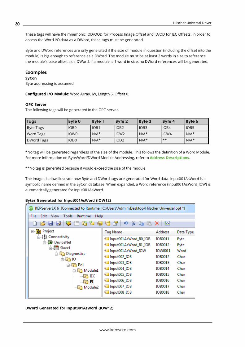
Byte and DWord references are only generated if the size of module in question (including the offset into themodule) is big enough to reference as a DWord. The module must be at least 2 words in size to referencethe module's base offset as a DWord. If a module is 1 word in size, no DWord references will be generated.
ExamplesSyConByte addressing is assumed.
Configured I/O Module:Word Array, IW, Length 6, Offset 0.
OPC ServerThe following tags will be generated in the OPC server.
Tags Byte 0 Byte 1 Byte 2 Byte 3 Byte 4 Byte 5Byte Tags IOB0 IOB1 IOB2 IOB3 IOB4 IOB5
Word Tags IOW0 N/A* IOW2 N/A* IOW4 N/A*
DWord Tags IOD0 N/A* IOD2 N/A* ** N/A*
*No tag will be generated regardless of the size of the module. This follows the definition of a Word Module.For more information on Byte/Word/DWordModule Addressing, refer to Address Descriptions.
**No tag is generated because it would exceed the size of the module.
The images below illustrate how Byte and DWord tags are generated for Word data. Input001AsWord is asymbolic name defined in the SyCon database. When expanded, a Word reference (Input001AsWord_IOW) isautomatically generated for Input001AsWord.
Bytes Generated for Input001AsWord (IOW12)
DWord Generated for Input001AsWord (IOW12)
www.kepware.com
30

Hilscher Universal Driver
32 bit Data ExpansionDWord references are automatically generated for 32 bit I/O Data if the "Expanded SyCon Tag Import"option is enabled under SyCon Database. Additionally, 32 bit I/O Data can be referenced as 8-Bit and 16 bitentities. These options will automatically generate Byte and/or Word references at the same offsets as theDWord reference.
Byte Reference Tags for 32-bit I/OThese tags will have the mnemonic IOB/OOB for Process Image Offset and IB/QB for IEC Offsets. In order toaccess the Bytes of DWordModule data, these tags must be generated.
Word Reference Tags for 32-bit I/OThese tags will have the mnemonic IOW/OOW for Process Image Offset and IW/QW for IEC Offsets. In orderto access the Words of DWordModule data, these tags must be generated.
ExamplesSyConByte Addressing is assumed.
Configured I/O Module: DWORD Array, ID, Length 4, Offset 0
OPC ServerThe following tags will be generated in the OPC server.
Tags Byte 0 Byte 1 Byte 2 Byte 3Byte Tags IOB0 IOB1 IOB2 IOB3
Word Tags IOW0 N/A* IOW2 N/A*
DWord Tags IOD0 N/A* N/A* N/A*
*No tag will be generated regardless of the size of the module. This follows the definition of a Word Module.For more information on Byte/Word/DWordModule Addressing, refer to Address Descriptions.
www.kepware.com
31
Hilscher Universal Driver
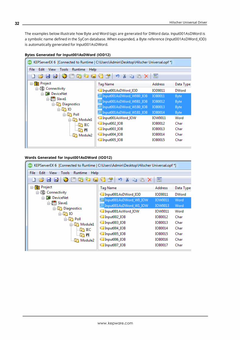
The examples below illustrate how Byte andWord tags are generated for DWord data. Input001AsDWord isa symbolic name defined in the SyCon database. When expanded, a Byte reference (Input001AsDWord_IOD)is automatically generated for Input001AsDWord.
Bytes Generated for Input001AsDWord (IOD12)
Words Generated for Input001AsDWord (IOD12)
www.kepware.com
32

Hilscher Universal Driver
Device SetupThe device represents a single device in the SyCon Configuration Database. It can be a Master or a Slave.
Connection TimeoutThis property specifies the time that the driver will wait for a connection to be made with a device.Depending on network load, the connect time may vary with each connection attempt. The default setting is3 seconds. The valid range is 1 to 30 seconds.
Request TimeoutThis property specifies the time that the driver will wait for a response from the device before giving up andgoing on to the next request. Longer timeouts only affect performance if a device is not responding. Thedefault setting is 1000 milliseconds. The valid range is 100 to 30000 milliseconds.
Retry AttemptsThis property specifies the number of times that the driver will retry a message before giving up and goingon to the next message. The default setting is 3 retries. The valid range is 1 to 10.
Device IDsThe Device ID represents the MAC ID in SyCon. Its range varies from bus to bus. The Device ID allowsAutomatic Tag Database Generation to import the proper tags for a given device.
Device Type
Description of the property is as follows:
l Type:When applicable, this property defines the device's bus type andmaster/slave type. Supporteddevice types include DeviceNet Master, DeviceNet Slave, Profibus-DP Master, and Profibus-DP Slave.
Note:Diagnostics may be accessed from the device specified as the Master.
www.kepware.com
33

Hilscher Universal Driver
Data Types Description
DataType
Description
Boolean Single bit
Byte Unsigned 8 bit value
Char Signed 8 bit value
Word Unsigned 16 bit value
bit 0 is the low bitbit 15 is the high bit
Short Signed 16 bit value
bit 0 is the low bitbit 14 is the high bitbit 15 is the sign bit
BCD Two byte packed BCD
Value range is 0-9999. Behavior is undefined for values beyond this range.
DWord Unsigned 32 bit value
bit 0 is the low bitbit 31 is the high bit
Long Signed 32 bit value
bit 0 is the low bitbit 30 is the high bitbit 31 is the sign bit
LBCD Four byte packed BCD
Value range is 0-99999999. Behavior is undefined for values beyond this range.
Float 32 bit floating point value.
The driver interprets two consecutive 16 bit registers as a floating point value by making thesecond register the high word and the first register the low word.
String Null terminated ASCII string
www.kepware.com
34

Hilscher Universal Driver
Address DescriptionsSelect an addressing type from the list below for specific address descriptions.
Process Image Address DescriptionsIEC Address Descriptions
Note: Process Image refers to addresses with syntax IOx and OOx. IEC refers to addresses with syntax Ixand Qx.
Process Image Address DescriptionsAddress mnemonic and offsets are based on the physical offset into the Master's Process Image MemoryMap (I/O Data). Addresses are always byte-based, regardless of the addressing mode selected in SyCon'sMaster Settings. The default data types for dynamically defined tags are shown in bold.
Note: The address ranges listed below are based on an 8K Dual-Port Memory.
Device Type Range Data Type AccessProcess Image Inputs IOX0.b-IOX3583.b*
.b is Bit 0-7 Byte Module
.b is Bit 0-15 WordModule
.b is Bit 0-31 DWordModule
IOB0-IOB3583
IOW0-IOW3582
IOD0-IOD3580
Boolean
Byte, Char, String**
Word, Short, BCD
DWord, Long, LBCD, Float
Read Only
Read Only
Read Only
Read Only
Process Image Outputs OOX0.b-OOX3583.b*.b is Bit 0-7 Byte Module.b is Bit 0-15 WordModule.b is Bit 0-31 DWordModule
OOB0-OOB3583
OOW0-OOW3582
OOD0-OOD3580
Boolean
Byte, Char, String**
Word, Short, BCD
DWord, Long, LBCD, Float
Write Only
Write Only
Write Only
Write Only
*These memory types/subtypes do not support arrays.
**Byte memory types (IOB) support Strings. The syntax for strings is <address>.<length> where 0 < length <=246.
Note 1: All offsets for memory types IO and OO represent a byte starting location within the specifiedmemory type.
Note 2:Use caution whenmodifying Word, Short, DWord and Long types. For I and Qmemory types,addresses may overlap depending on the module format and addressing type. It is recommended that thesememory types be used so that overlapping does not occur.
www.kepware.com
35

Hilscher Universal Driver
Note 3: For information on the proper referencing of Process Image data, refer toModule Format vs.Byte/Word Addressing.
ArraysAll memory types support arrays, excepting those marked with an asterisk (*). The syntax below is valid fordeclaring an array. If no rows are specified, row count of 1 is assumed.
<address>[rows][cols]
For Word, Short and BCD arrays, the base address + (rows *cols *2) cannot exceed 247. The array'selements are words and are located on a word boundary. For example, IOW0[4] will return IOW0, IOW2,IOW4, and IOW6 for both Byte andWord Addressing.
For Float, DWord, Long and Long BCD arrays, the base address + (rows *cols *4) cannot exceed 247. Thearray's elements are DWords and are located on a DWord boundary. For example, IOD0[4] will return IOD0,IOD4, IOD8, IOD12 for both Byte andWord Addressing.
For all arrays, the total number of bytes being requested cannot exceed the internal block size of 247 bytes.
Byte SwappingBytes can be swapped for 16 bit (Word, Short and BCD) and 32 bit (DWord, Long, Float and LBCD) data byappending an 'S' to the end of an address reference:
<address>S
For arrays (each element will be Byte swapped):
<address>S [rows][cols]
Below are examples to illustrate how Bytes are swapped for 16 and 32 bit data for both Little and Big Endian.Byte-ordering is unaffected by the Addressing Mode.
16 Bit DataIn the example below, an analog sensor maps to Offset 0. Sensor value=0x1234 (hex) == 4660 (dec).
Little Endian (LSB-MSB) - No Swap
DPM Byte Offset Data Byte Reference Word Reference DWord Reference0 0x34 IOB0=0x34 IOW0=0x1234 IOD0=0x00001234
1 0x12 IOB1=0x12
2 0x00 IOB2=0x00
3 0x00 IOB3=0x00
Little Endian (LSB-MSB) - Swap
DPM Byte Offset Data Byte Reference Word Reference DWord Reference0 0x34 IOB0=0x34 IOW0=0x3412 IOD0=0x34120000
1 0x12 IOB1=0x12
2 0x00 IOB2=0x00
3 0x00 IOB3=0x00
www.kepware.com
36

Hilscher Universal Driver
Big Endian (MSB-LSB) - No Swap
DPM Byte Offset Data Byte Reference Word Reference DWord Reference0 0x12 IOB0=0x12 IOW0=0x3412 IOD0=0x00003412
1 0x34 IOB1=0x34
2 0x00 IOB2=0x00
3 0x00 IOB3=0x00
Big Endian (MSB-LSB) - Swap
DPM Byte Offset Data Byte Reference Word Reference DWord Reference0 0x12 IOB0=0x12 IOW0=0x1234 IOD0=0x12340000
1 0x34 IOB1=0x34
2 0x00 IOB2=0x00
3 0x00 IOB3=0x00
32 Bit DataIn the example below, an analog sensor maps to Offset 0. Sensor value=0x12345678 (hex) == 305,419,896(dec).
Little Endian (LSB-MSB) - No Swap
DPM Byte Offset Data Byte Reference Word Reference DWord Reference0 0x78 IOB0=0x78 IOW0=0x5678 IOD0=0x12345678
1 0x56 IOB1=0x56
2 0x34 IOB2=0x34 IOW2=0x1234
3 0x12 IOB3=0x12
Little Endian (LSB-MSB) - Swap
DPM Byte Offset Data Byte Reference Word Reference DWord Reference0 0x78 IOB0=0x78 IOW0=0x7856 IOD0=0x78563412
1 0x56 IOB1=0x56
2 0x34 IOB2=0x34 IOW2=0x3412
3 0x12 IOB3=0x12
Big Endian (MSB-LSB) - No Swap
DPM Byte Offset Data Byte Reference Word Reference DWord Reference0 0x12 IOB0=0x12 IOW0=0x3412 IOD0=0x78563412
1 0x34 IOB1=0x34
2 0x56 IOB2=0x56 IOW2=0x7856
3 0x78 IOB3=0x78
Big Endian (MSB-LSB) - Swap
www.kepware.com
37

Hilscher Universal Driver
DPM Byte Offset Data Byte Reference Word Reference DWord Reference0 0x12 IOB0=0x12 IOW0=0x1234 IOD0=0x12345678
1 0x34 IOB1=0x34
2 0x56 IOB2=0x56 IOW2=0x5678
3 0x78 IOB3=0x78
Note 1: Cautionmust be exercised when referencing overlappedmemory. For example, IW1S will corruptIW0S (and vice-versa). Overlapping references is not recommended.
Note 2: SyCon allows for swapping via Symbolic Names under Long andWord Details
Module Format vs. Byte/Word AddressingModule Format refers to the width of the Module configured in SyCon. Supported formats include Byte, Wordand DWord. Addressing Modes below refer to the Addressing Mode under Master Settings in SyCon. Byte 0 -Byte n refer to the Byte Offsets in the Process Image. Regions highlighted in Yellow exemplify the Bytesinvolved in a reference at Offset 0 for the givenmemory type (i.e., IOD0 will contain Byte 0-Byte 3). They alsoillustrates howWords and DWords can overlap. Exercise caution when referencing overlappedWords andDWords.
Byte Module (8-Bit Module Data)For Byte Modules, Byte memory is treated as a Byte. There are no N/A references.
Byte AddressingByte 0 Byte 1 Byte 2 Byte 3 Byte 4IOX0.0-7 IOX1.0-7 IOX2.0-7 IOX3.0-7 IOX4.0-7
IOB0 IOB1 IOB2 IOB3 IOB4
IOW0 IOW1 IOW2 IOW3 IOW4
IOD0 IOD1 IOD2 IOD3 IOD4
Table x: Byte Module Byte PI Addressing
Word AddressingByte 0 Byte 1 Byte 2 Byte 3 Byte 4IOX0.0-7 IOX1.0-7 IOX2.0-7 IOX3.0-7 IOX4.0-7
IOB0 IOB1 IOB2 IOB3 IOB4
IOW0 IOW1 IOW2 IOW3 IOW4
IOD0 IOD1 IOD2 IOD3 IOD4
Table x: Byte Module Word PI Addressing
Word Module (16 bit Module Data)For Word Modules, Byte memory is treated as a Word with the exception of IOB. N/A references are due tothis Word alignment for the module.
Byte AddressingByte 0 Byte 1 Byte 2 Byte 3 Byte 4IOX0.0-15 N/A IOX2.0-15 N/A IOX4.0-15
IOB0 IOB1 IOB2 IOB3 IOB4
IOW0 N/A IOW2 N/A IOW4
IOD0 N/A IOD2 N/A IOD4
www.kepware.com
38

Hilscher Universal Driver
Table x: Word Module Byte PI Addressing
Word AddressingByte 0 Byte 1 Byte 2 Byte 3 Byte 4IOX0.0-15 N/A IOX2.0-15 N/A IOX4.0-15
IOB0 IOB1 IOB2 IOB3 IOB4
IOW0 N/A IOW2 N/A IOW4
IOD0 N/A IOD2 N/A IOD4
Table x: Word Module Word PI Addressing
DWord Module (32 bit Module Data)For DWordModules, Byte memory is treated as a DWord with the exception of IOB and IOW. N/A referencesare due to this DWord alignment for the module.
Byte AddressingByte 0 Byte 1 Byte 2 Byte 3 Byte 4IOX0.0-31 N/A N/A N/A IOX4.0-31
IOB0 IOB1 IOB2 IOB3 IOB4
IOW0 N/A IOW2 N/A IOW4
IOD0 N/A N/A N/A IOD4
Table x: DWord Module Byte PI Addressing
Word AddressingByte 0 Byte 1 Byte 2 Byte 3 Byte 4IOX0.0-31 N/A N/A N/A IOX4.0-31
IOB0 IOB1 IOB2 IOB3 IOB4
IOW0 N/A IOW2 N/A IOW4
IOD0 N/A N/A N/A IOD4
Table x: DWord Module Word PI Addressing
IEC Address DescriptionsAddress mnemonic and offsets are based on standard Siemens addressing (IB, IW, ID). Addresses are byte-based or word-based, depending on the addressing mode selected in SyCon's Master Settings. The defaultdata types for dynamically defined tags are shown in bold.
Note: The address ranges listed below are based on an 8K Dual-Port Memory.
Device Type Range Data Type AccessProcess Image Inputs IX0.b-IX3583.b*
.b is Bit 0-7 Byte Module
.b is Bit 0-15 WordModule
.b is Bit 0-31 DWordModule
IB0-IB3583
IW0-IW3582
ID0-ID3580
Boolean
Byte, Char, String**
Word, Short, BCD
DWord, Long, LBCD, Float
Read Only
Read Only
Read Only
Read Only
www.kepware.com
39
Hilscher Universal Driver
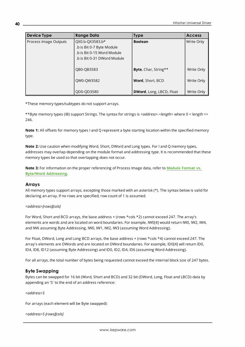
Device Type Range Data Type AccessProcess Image Outputs QX0.b-QX3583.b*
.b is Bit 0-7 Byte Module
.b is Bit 0-15 WordModule
.b is Bit 0-31 DWordModule
QB0-QB3583
QW0-QW3582
QD0-QD3580
Boolean
Byte, Char, String**
Word, Short, BCD
DWord, Long, LBCD, Float
Write Only
Write Only
Write Only
Write Only
*These memory types/subtypes do not support arrays.
**Byte memory types (IB) support Strings. The syntax for strings is <address>.<length> where 0 < length <=246.
Note 1: All offsets for memory types I and Q represent a byte starting location within the specified memorytype.
Note 2:Use caution whenmodifying Word, Short, DWord and Long types. For I and Qmemory types,addresses may overlap depending on the module format and addressing type. It is recommended that thesememory types be used so that overlapping does not occur.
Note 3: For information on the proper referencing of Process Image data, refer toModule Format vs.Byte/Word Addressing.
ArraysAll memory types support arrays, excepting those marked with an asterisk (*). The syntax below is valid fordeclaring an array. If no rows are specified, row count of 1 is assumed.
<address>[rows][cols]
For Word, Short and BCD arrays, the base address + (rows *cols *2) cannot exceed 247. The array'selements are words and are located on word boundaries. For example, IW0[4] would return IW0, IW2, IW4,and IW6 assuming Byte Addressing, IW0, IW1, IW2, IW3 (assuming Word Addressing).
For Float, DWord, Long and Long BCD arrays, the base address + (rows *cols *4) cannot exceed 247. Thearray's elements are DWords and are located on DWord boundaries. For example, ID0[4] will return ID0,ID4, ID8, ID12 (assuming Byte Addressing) and ID0, ID2, ID4, ID6 (assuming Word Addressing).
For all arrays, the total number of bytes being requested cannot exceed the internal block size of 247 bytes.
Byte SwappingBytes can be swapped for 16 bit (Word, Short and BCD) and 32 bit (DWord, Long, Float and LBCD) data byappending an 'S' to the end of an address reference:
<address>S
For arrays (each element will be Byte swapped):
<address>S [rows][cols]
www.kepware.com
40

Hilscher Universal Driver
The examples below illustrate how Bytes are swapped for 16 and 32 bit data for both Little and Big Endian.Byte-ordering is unaffected by the addressing ,ode.
16 bit DataIn the example below, an analog sensor maps to Offset 0. Sensor value=0x1234 (hex) == 4660 (dec).
Little Endian (LSB-MSB) - No Swap
DPM Byte Offset Data Byte Reference Word Reference DWord Reference0 0x34 IB0=0x34 IW0=0x1234 ID0=0x00001234
1 0x12 IB1=0x12
2 0x00 IB2=0x00
3 0x00 IB3=0x00
Little Endian (LSB-MSB) - Swap
DPM Byte Offset Data Byte Reference Word Reference DWord Reference0 0x34 IB0=0x34 IW0=0x3412 ID0=0x34120000
1 0x12 IB1=0x12
2 0x00 IB2=0x00
3 0x00 IB3=0x00
Big Endian (MSB-LSB) - No Swap
DPM Byte Offset Data Byte Reference Word Reference DWord Reference0 0x12 IB0=0x12 IW0=0x3412 ID0=0x00003412
1 0x34 IB1=0x34
2 0x00 IB2=0x00
3 0x00 IB3=0x00
Big Endian (MSB-LSB) - Swap
DPM Byte Offset Data Byte Reference Word Reference DWord Reference0 0x12 IB0=0x12 IW0=0x1234 ID0=0x12340000
1 0x34 IB1=0x34
2 0x00 IB2=0x00
3 0x00 IB3=0x00
32 Bit DataIn the example below, an analog sensor maps to Offset 0. Sensor value=0x12345678 (hex) == 305,419,896(dec).
Little Endian (LSB-MSB) - No Swap
DPM Byte Offset Data Byte Reference Word Reference DWord Reference0 0x78 IB0=0x78 IW0=0x5678 ID0=0x12345678
www.kepware.com
41

Hilscher Universal Driver
DPM Byte Offset Data Byte Reference Word Reference DWord Reference1 0x56 IB1=0x56
2 0x34 IB2=0x34 IW1=0x1234
3 0x12 IB3=0x12
Little Endian (LSB-MSB) - Swap
DPM Byte Offset Data Byte Reference Word Reference DWord Reference0 0x78 IB0=0x78 IW0=0x7856 ID0=0x78563412
1 0x56 IB1=0x56
2 0x34 IB2=0x34 IW1=0x3412
3 0x12 IB3=0x12
Big Endian (MSB-LSB) - No Swap
DPM Byte Offset Data Byte Reference Word Reference DWord Reference0 0x12 IB0=0x12 IW0=0x3412 ID0=0x78563412
1 0x34 IB1=0x34
2 0x56 IB2=0x56 IW1=0x7856
3 0x78 IB3=0x78
Big Endian (MSB-LSB) - Swap
DPM Byte Offset Data Byte Reference Word Reference DWord Reference0 0x12 IB0=0x12 IW0=0x1234 ID0=0x12345678
1 0x34 IB1=0x34
2 0x56 IB2=0x56 IW1=0x5678
3 0x78 IB3=0x78
Note 1: Cautionmust be exercised when referencing overlappedmemory. For example, IW1S will corruptIW0S (and vice-versa). Overlapping references is not recommended.
Note 2: SyCon allows for swapping via symbolic names under Long andWord Details
Module Format vs. Byte/Word AddressingModule Format refers to the width of the Module configured in SyCon. Supported formats include Byte, Wordand DWord. The addressing modes below refer to SyCon's Addressing Mode settings. Byte 0-Byte n refer tothe Byte Offsets in the Process Image. Regions highlighted in Yellow exemplify the Bytes involved in areference at Offset 0 for the givenmemory type (ie ID0 will contain Byte 0-Byte 3). They also illustrates howWords and DWords can overlap. Exercise caution when referencing overlappedWords and DWords.
Byte Module (8-Bit Module Data)For Byte Modules, Byte memory is treated as a Byte. There are no N/A references.
Byte AddressingByte 0 Byte 1 Byte 2 Byte 3 Byte 4IX0.0-7 IX1.0-7 IX2.0-7 IX3.0-7 IX4.0-7
www.kepware.com
42

Hilscher Universal Driver
Byte 0 Byte 1 Byte 2 Byte 3 Byte 4IB0 IB1 IB2 IB3 IB4
IW0 IW1 IW2 IW3 IW4
ID0 ID1 ID2 ID3 ID4
Table x: Byte Module Byte IEC Addressing
Word AddressingByte 0 Byte 1 Byte 2 Byte 3 Byte 4IX0.0-7 N/A IX1.0-7 N/A IX2.0-7
IB0 N/A IB1 N/A IB2
IW0 N/A IW1 N/A IW2
ID0 N/A ID1 N/A ID2
Table x: Byte Module Word IEC Addressing
Word Module (16 bit Module Data)For Word Modules, Byte memory is treated as a Word (with the exception of IOB). N/A references are due tothe Word alignment for the module.
Byte AddressingByte 0 Byte 1 Byte 2 Byte 3 Byte 4IX0.0-15 N/A IX2.0-15 N/A IX4.0-15
IB0 IB1 IB2 IB3 IB4
IW0 N/A IW2 N/A IW4
ID0 N/A ID2 N/A ID4
Table x: Word Module Byte IEC Addressing
Word AddressingByte 0 Byte 1 Byte 2 Byte 3 Byte 4IX0.0-15 N/A IX1.0-15 N/A IX2.0-15
IB0 N/A IB1 N/A IB2
IW0 N/A IW1 N/A IW2
ID0 N/A ID1 N/A ID2
Table x: Word Module Word IEC Addressing
DWord Module (32 bit Module Data)For DWordModules, Byte memory is treated as a DWord (with the exception of IOB and IOW). N/Areferences are due to the DWord alignment for the module.
Byte AddressingByte 0 Byte 1 Byte 2 Byte 3 Byte 4IX0.0-31 N/A N/A N/A IX4.0-31
IB0 IB1 IB2 IB3 IB4
IW0 N/A IW2 N/A IW4
ID0 N/A N/A N/A ID4
Table x: DWord Module Byte IEC Addressing
Word Addressing
www.kepware.com
43

Hilscher Universal Driver
Byte 0 Byte 1 Byte 2 Byte 3 Byte 4IX0.0-31 N/A N/A N/A IX2.0-31
IB0 N/A IB1 N/A IB2
IW0 N/A IW1 N/A IW2
ID0 N/A N/A N/A ID2
Table x: DWord Module Word IEC Addressing
www.kepware.com
44

Hilscher Universal Driver
Automatic Tag Database GenerationAutomatic Tag Database Generation is a feature of the Hilscher Universal Driver that provides in order toimport the SyCon Configuration Database into the OPC server. The specification of the SyCon Configurationfile is made at the channel level; meaning, all devices under a channel will be based on the same SyConConfiguration file.
Module definitions, module settings, configured I/O and SyCon symbolic names are imported in tagdatabase generation. In addition, diagnostics for both Master and Slaves are generated. This importcapability leaves all the configuration to be done in SyCon with little configuration necessary in the OPCserver.
See Also:Options
How to Perform Automatic Tag GenerationTo begin, ensure that devices have been defined under a channel. Remember that the Device ID is the MACID in SyCon. To perform automatic tag generation, navigate to Channel Properties | SyCon Database.Click on the “Synchronize tags” link to generate the tags.
Tags (I/O and Diagnostics) will be generated for each device under the given channel. Wait until the processis complete before editing Device Properties, Channel Properties and the SyCon Configuration Database.
Information Imported From DatabaseMasterAddressing Mode (Byte vs Word-Based Addressing)
SlaveModule Format (Byte, Word, or DWordModule)Byte Swapping (Symbolic Name Swap Option)
Information Not Imported From DatabaseDevice NamesMessage Definitions (Explicit Messages, DPV1, etc)String-type Symbolic Names
Tags Generated In ServerMasterDiagnostic Tags
The image below is an example of the diagnostic tags available for a DeviceNet Master. The exactdiagnostic tags generated depends on the bus as specified under Channel Properties | Board Type.
www.kepware.com
45

Hilscher Universal Driver
SlaveI/O Data Tags (SyCon Symbolic Names)Diagnostic Tags (if applicable)
SyCon I/O tags defined in the SyCon Configuration Database will be imported and a server tag generated foreach. Also, if Expanded SyCon Tag Import is enabled, additional tags will be generated based on both theSyCon I/O tags and the expansion settings selected. The image below displays the tags and tag groupsgenerated for three DeviceNet devices with Expanded SyCon Tag Import enabled.
www.kepware.com
46

Hilscher Universal Driver
Note: For more information on Expanded SyCon I/O Tag Import, refer to I/O Data References andAddressing Type.
www.kepware.com
47

Hilscher Universal Driver
Error DescriptionsThe following error/warning messages may be generated. Click on the link for a description of the message.
Address ValidationMissing addressDevice address '<address>' contains a syntax errorAddress '<address>' is out of range for the specified device or registerData Type '<type>' is not valid for device address '<address>'Device address '<address>' is Read OnlyArray size is out of range for address '<address>'Array support is not available for the specified address: '<address>'
Driver Error MessagesUnable to load '<dll>'Unable to import from '<dll>'DevOpenDriver () failed with error code '<code>'Memory allocation error
Device Status MessagesDevice '<device name>' is not respondingUnable to read device info data in area '<area>'. Board '<board>' returned Error Code'<code>'Unable to read '<block size>' device info bytes in area '<area>'. Board '<board>' returnedError Code '<code>'Unable to read task state data in task '<task num>'. Board '<board>' returned Error Code'<code>'Unable to read '<block size>' task state bytes in task '<task num>'. Board '<board>'returned Error Code '<code>'Unable to read tag '<address>' from device '<device>'. Board '<board>' returned ErrorCode '<code>'Unable to read '<block size>' bytes starting at '<address>' from device '<device>'. Board'<board>' returned Error Code '<code>'Unable to write to tag '<address>' from device '<device>'. Board '<board>' returned ErrorCode '<code>'Unable to read tag '<name>': msg.b <command>, msg.device_adr <Device ID>Unable to read '<block size>' message bytes: msg.b <command>, msg.device_adr <DeviceID>...Unable to write to tag '<address>': msg.b <command>, msg.device_adr <Device ID>...Unable to read tag '<address>' from device '<device>'. Board '<board>' returned DPMDiagnostics [Global Bits='<Global Bits>', Node='<Remote Address>', Code='<Error Event>']Unable to read '<block size>' bytes starting at '<address>' from device '<device>'. Board'<board>' returned DPM Diagnostics [Global Bits='<Global Bits>', Node='<RemoteAddress>', Code='<Error Event>']Unable to write to tag '<address>' from device '<device>'. Board '<board>' returned DPMDiagnostics [Global Bits='<Global Bits>', Node='<Remote Address>', Code='<Error Event>']
www.kepware.com
48

Hilscher Universal Driver
Unable to read tag '<address>' from device '<device>'. Board '<board>' returned DNMDiagnostics [Global Bits='<Global Bits>', Node='<Device Address>', Code='<Error Event>']Unable to read '<block size>' bytes starting at '<address>' from device '<device>'. Board'<board>' returned DNM Diagnostics [Global Bits='<Global Bits>', Node='<DeviceAddress>', Code='<Error Event>']Unable to write to tag '<address>' from device '<device>'. Board '<board>' returned DNMDiagnostics [Global Bits='<Global Bits>', Node='<Device Address>', Code='<Error Event>']
Automatic Tag Database Generation MessagesThe file is not a valid Sycon database or may be corruptAuto tag database generation cannot be performed while the driver is processing tagsBoard Type for Board '<board number>' does not match the actual board installed. VerifyBoard Type and/or Board SelectionBoard Type for Board '<board number> does not match the Slave Type for one or moreSlaves configured. Delete or edit Slaves accordingly'dbm32.dll' is not loaded and is required for auto tag generation. Verify SyCon isinstalled
Error CodesCIF Device Driver ErrorsErrorCode
Source Description
-1 CIFDriver
The communication board is not initialized by the driver.
-Check the driver configuration.-Driver function used without calling DevOpenDriver () first.
-2 CIFDriver
Error in internal 'Init State'.
-3 CIFDriver
Error in internal 'Read State'.
-4 CIFDriver
Command on this channel is active.
-5 CIFDriver
Unknown parameter in function occurred.
-6 CIFDriver
Version is incompatible. The device driver version does not correspond to the driverDLL version. From version V1.200 the internal command structure between DLL anddriver has changed. Make sure to use the same version of the device driver and thedriver DLL.
-10 Device Dual port memory RAM is not accessible/no hardware found. This error occurs whenthe driver is not able to read or write to the Dual port memory.
-Check the BIOS setting of the PC.
Memory address conflict with other PC components, try another memory address.
-Check the driver configuration for this board-Check the jumper settings of the board.
www.kepware.com
49

Hilscher Universal Driver
ErrorCode
Source Description
-11 Device Not ready (RDY flag=Ready flag failed). Board is not ready. This could be a hardwaremalfunction or another program writes inadmissible to the dual port memory.
-12 Device Not running (RUN flag=Running flag failed). The board is ready but not all tasks arerunning because of an initialization error.
-No database is loaded into the device or an invalid parameter has been set so that atask cannot initialize.
-13 Device Watchdog test failed.
-14 Device Signals wrong Operating System version. No license code found on the communicationboard.
-Device has no license for the used operating system or customer software.-No firmware or no database on the device is loaded.
-15 Device Error in dual port memory flags.
-16 Device Sendmailbox is full.
-17 Device Function PutMessage timeout.
-If using an interrupt, check the interrupt on the device and in driver setup. Thesesettings have to be the same. Is an interrupt on the board set? Is the right interruptset? The interrupt could already be used by another PC component.-If using polling mode, make sure that no interrupt is set on the board and that pollingis set in the driver setup. The settings have to be the same.-Device internal segment buffer full.DevSetHostState not called.
-18 Device Function GetMessage timeout.
-If using an interrupt, check the interrupt on the device and in driver setup. Thesesettings have to be the same. Is an interrupt on the board set? Is the right interruptset? The interrupt could already be used by another PC component.-If using polling mode, make sure that no interrupt is set on the board and that pollingis set in the driver setup. The settings have to be the same.
-19 Device Nomessage available.
-20 Device Reset command timeout.
-The board is ready but not all tasks are running because of an initialization error.-No database is loaded into the device.-If using an interrupt, check the interrupt on the device and in driver setup. Thesesettings have to be the same. Is an interrupt on the board set? Is the right interruptset? The interrupt could already be used by another PC component.-If using polling mode, make sure that no interrupt is set on the board and that pollingis set in the driver setup. The settings have to be the same.
-21 Device COM flag not set. The device cannot reach communication state.
-Device not connected to the fieldbus.-No station found on the fieldbus.-Wrong configuration on the device.
www.kepware.com
50

Hilscher Universal Driver
ErrorCode
Source Description
-22 Device I/O data exchange failed.
-23 Device I/O data exchange timeout.
-If using an interrupt, check the interrupt on the device and in driver setup. Thesesettings have to be the same. Is an interrupt on the board set? Is the right interruptset? The interrupt could already be used by another PC component.-If using polling mode, thenmake sure that no interrupt is set on the board and thatpolling is set in the driver setup. The settings have to be the same.
-24 Device I/O data mode unknown.
-25 Device Function call failed.
-26 Device Dual port memory size differs from configuration.
-27 Device State mode unknown.
-30 User Driver not opened (device driver not loaded).
-Device driver not installed.-Wrong parameters in the driver configuration.
-31 User Can't connect with device board.
-32 User Board not initialized.
-DevInitBoard () not called.
-33 User IOCTRL function failed.
-Make sure to use a device driver and DLL with the same version.
-34 User Parameter DeviceNumber invalid.
-35 User Parameter InfoArea unknown.
-36 User Parameter Number invalid.
-37 User Parameter Mode invalid.
-38 User NULL pointer assignment.
-39 User Message buffer too short.
-40 User Size parameter invalid.
-42 User Size parameter with zero length.
-43 User Size parameter too long.
-44 User Device address null pointer.
-45 User Pointer to buffer is a null pointer.
-46 User SendSize parameter too long.
-47 User ReceiveSize parameter too long.
-48 User Pointer to send buffer is a null pointer.
-49 User Pointer to receive buffer is a null pointer.
Address ValidationThe following error/warning messages may be generated. Click on the link for a description of the message.
Address ValidationMissing addressDevice address '<address>' contains a syntax error
www.kepware.com
51

Hilscher Universal Driver
Address '<address>' is out of range for the specified device or registerData Type '<type>' is not valid for device address '<address>'Device address '<address>' is Read OnlyArray size is out of range for address '<address>'Array support is not available for the specified address: '<address>'
Missing addressError Type:Warning
Possible Cause:A tag address that has been specified statically has no length.
Solution:Re-enter the address in the client application.
Device address '<address>' contains a syntax errorError Type:Warning
Possible Cause:A tag address that has been specified statically contains one or more invalid characters.
Solution:Re-enter the address in the client application.
Address <address>' is out of range for the specified device or registerError Type:Warning
Possible Cause:A tag address that has been specified statically references a location that is beyond the range of supportedlocations for the device.
Solution:Verify the address is correct; if it is not, re-enter it in the client application.
Data Type '<type>' is not valid for device address '<address>'Error Type:Warning
Possible Cause:A tag address that has been specified statically has been assigned an invalid data type.
Solution:Modify the requested data type in the client application.
www.kepware.com
52

Hilscher Universal Driver
Device address '<address>' is Read OnlyError Type:Warning
Possible Cause:A tag address that has been specified statically has a requested access mode that is not compatible withwhat the device supports for that address.
Solution:Change the access mode in the client application.
Array size is out of range for address '<address>'Error Type:Warning
Possible Cause:A tag address that has been specified statically is requesting an array size that is too large for the addresstype or block size of the driver.
Solution:Re-enter the address in the client application to specify a smaller value for the array or a different startingpoint.
Array Support is not available for the specified address: '<address>'Error Type:Warning
Possible Cause:A tag address that has been specified statically contains an array reference for an address type that doesn'tsupport arrays.
Solution:Re-enter the address in the client application to remove the array reference or correct the address type.
Driver Error MessagesThe following error/warning messages may be generated. Click on the link for a description of the message.
Driver Error MessagesUnable to load '<dll>'Unable to import from '<dll>'DevOpenDriver () failed with error code '<code>'Memory allocation error
Unable to load '<dll>'Error Type:Serious
Possible Cause:
www.kepware.com
53

Hilscher Universal Driver
A software component necessary to communicate with the Hilscher card or SyCon configuration databasecannot be loaded.
Solution:Verify that the latest version of SyCon is installed on the same machine as the OPC server and then tryagain.
Unable to import from '<dll>'Error Type:Serious
Possible Cause:The interface necessary to communicate with the Hilscher card or SyCon configuration database, cannot beloaded from <dll>.
Solution:Verify that the latest version of SyCon is installed on the same machine as the OPC server and try again.
DevOpenDriver () failed with error code '<code>'Error Type:Serious
Possible Cause:Unable to load the device drivers necessary for card communications.
Solution:Refer to the Error Codes table for specific information.
See Also:Error Codes
Memory allocation errorError Type:Serious
Possible Cause:Memory required to driver operations could not be allocated.
Solution:Close any unused applications and/or increase the amount of virtual memory. Then, try again.
Device Status MessagesThe following error/warning messages may be generated. Click on the link for a description of the message.
Device Status MessagesDevice '<device name>' is not respondingUnable to read device info data in area '<area>'. Board '<board>' returned Error Code'<code>'
www.kepware.com
54

Hilscher Universal Driver
Unable to read '<block size>' device info bytes in area '<area>'. Board '<board>' returnedError Code '<code>'Unable to read task state data in task '<task num>'. Board '<board>' returned Error Code'<code>'Unable to read '<block size>' task state bytes in task '<task num>'. Board '<board>'returned Error Code '<code>'Unable to read tag '<address>' from device '<device>'. Board '<board>' returned ErrorCode '<code>'Unable to read '<block size>' bytes starting at '<address>' from device '<device>'. Board'<board>' returned Error Code '<code>'Unable to write to tag '<address>' from device '<device>'. Board '<board>' returned ErrorCode '<code>'Unable to read tag '<name>': msg.b <command>, msg.device_adr <Device ID>Unable to read '<block size>' message bytes: msg.b <command>, msg.device_adr <DeviceID>Unable to write to tag '<address>': msg.b <command>, msg.device_adr <Device ID>Unable to read tag '<address>' from device '<device>'. Board '<board>' returned DPMDiagnostics [Global Bits='<Global Bits>', Node='<Remote Address>', Code='<Error Event>']Unable to read '<block size>' bytes starting at '<address>' from device '<device>'. Board'<board>' returned DPM Diagnostics [Global Bits='<Global Bits>', Node='<RemoteAddress>', Code='<Error Event>']Unable to write to tag '<address>' from device '<device>'. Board '<board>' returned DPMDiagnostics [Global Bits='<Global Bits>', Node='<Remote Address>', Code='<Error Event>']Unable to read tag '<address>' from device '<device>'. Board '<board>' returned DNMDiagnostics [Global Bits='<Global Bits>', Node='<Device Address>', Code='<Error Event>']Unable to read '<block size>' bytes starting at '<address>' from device '<device>'. Board'<board>' returned DNM Diagnostics [Global Bits='<Global Bits>', Node='<DeviceAddress>', Code='<Error Event>']Unable to write to tag '<address>' from device '<device>'. Board '<board>' returned DNMDiagnostics [Global Bits='<Global Bits>', Node='<Device Address>', Code='<Error Event>']
Device '<device name>' is not respondingError Type:Warning
Result:If the tag was being read:
l If tag is a block tag, the entire block will be invalidated. All tags within that block will be invalidated.
l If tag is an array tag or string tag, just this tag is invalidated.
If the tag was being written:
l Write operation for the given tag will not take place.
Possible Cause:
www.kepware.com
55

Hilscher Universal Driver
1. The connection between the device and the Host PC is broken.
2. Device CPU work load is too high.
3. The response from the device took longer to receive than the amount of time specified in the"Request Timeout" device setting.
Solution:
1. Verify the cabling between the PC and the PLC device.
2. If this error occurs frequently, decrease the tag group scan rate to reduce the work load on the PLCCPU.
3. Increase the Request Timeout setting so that the entire response can be handled.
Unable to read device info data in area '<area>'. Board '<board>' returnedError Code '<code>'Error Type:Warning
Possible Cause:Device info data contains diagnostics information for most Master cards. Some device info data is readindividually while other device info data are structured and read as a block. This error pertains to the former.Read access to this data failed.
Solution:Refer to the Error Codes table for specific information.
See Also:Error Codes
Unable to read '<block size>' device info bytes in area '<area>'. Board'<board>' returned Error Code '<code>'Error Type:Warning
Possible Cause:Device info data contains diagnostics information for most Master cards. Some device info are readindividually while other device info data are structured and read as a block. This error pertains to the latter.Read access to this data failed.
Solution:Refer to the Error Codes table for specific information.
See Also:Error Codes
www.kepware.com
56

Hilscher Universal Driver
Unable to read task state data in task '<task num>'. Board '<board>' returnedError Code '<code>'Error Type:Warning
Possible Cause:Task state data contains diagnostics information for some Slave cards. Some task data is read individuallywhile other device info data are structured and read as a block. This error pertains to the former. Readaccess to this data failed.
Solution:Refer to the Error Codes table for specific information.
See Also:Error Codes
Unable to read '<block size>' task state bytes in task '<task num>'. Board'<board>' returned Error Code '<code>'Error Type:Warning
Possible Cause:Task state data contains diagnostics information for some Slave cards. Some task data is read individuallywhile other device info data are structured and read as a block. This error pertains to the latter. Read accessto this data failed.
Solution:Refer to the Error Codes table for specific information.
See Also:Error Codes
Unable to read tag '<address>' from device '<device>'. Board '<board>'returned Error Code '<code>'Error Type:Warning
Possible Cause:The driver was unable to read the data at offset '<address>' in '<board>'s Input image. This data locationcorresponds to Input data mapped for device '<device>'. This error pertains to all string and array I/O tags.
Solution:Refer to the Error Codes table for specific information.
See Also:Error Codes
www.kepware.com
57

Hilscher Universal Driver
Unable to read '<block size>' bytes starting at '<address>' from device'<device>'. Board '<board>' returned Error Code '<code>'Error Type:Warning
Possible Cause:The driver was unable to read '<block size>' bytes of data, starting at offset '<address>', in '<board>'s Inputimage. These data locations correspond to Input data mapped for device '<device>'. This error pertains to allnon-string and non-array I/O tags.
Solution:Refer to the Error Codes table for specific information.
See Also:Error Codes
Unable to write to tag '<address>' from device '<device>'. Board '<board>'returned Error Code '<code>'Error Type:Warning
Possible Cause:A write failed to offset '<address>' in '<board>'s Output image, corresponding to Output data mapped todevice '<device>'.
Solution:Refer to the Error Codes table for specific information.
See Also:Error Codes
Unable to read tag '<name>': msg.b=<command>, msg.device_adr=<DeviceID>...Error Type:Warning
Possible Cause:The driver was unable to read tag '<name>' because the message associated with '<name>' failed or theresponse from the message was invalid. The message command and destination device are listed as<command> and <Device ID> respectively. Applicable for diagnostics only.
l Refer to the Error Codes table if the following message is received:"...Get message failed on Board '<board>' with Error Code '<code>"
l Either the destination for the message was invalid or unexpected data was received the followingmessage is received:"...Response from Board '<board>' contains a framing error"
Solution:Re-download the configuration database in SyCon.
www.kepware.com
58

Hilscher Universal Driver
See Also:Error Codes
Unable to read '<block size>' message bytes: msg.b=<command>,msg.device_adr=<Device ID>...Error Type:Warning
Possible Cause:The driver was unable to read <block size> bytes of data requested in message <command>, from device<Device ID> because the message failed or the response from the message was invalid. The messagecommand and destination device are listed as <command> and <Device ID> respectively. Applicable fordiagnostics only.
l Refer to the Error Codes table if the following message is received:"...Get message failed on Board '<board>' with Error Code '<code>"
l Either the destination for the message was invalid or unexpected data was received if the followingmessage is received:"...Response from Board '<board>' contains a framing error"
Solution:Re-download the configuration database in SyCon.
See Also:Error Codes
Unable to read tag '<address>' from device '<device>'. Board '<board>'returned DPM Diagnostics [Global Bits='<Global Bits>', Node='<RemoteAddress>', Code='<Error Event>']Error Type:Warning
Possible Cause:The driver was unable to read the data at offset '<address>' in '<board>'s Input image. This data locationcorresponds to Input data mapped for device '<device>'. This error pertains to all non-string and non-arrayI/O tags.
Solution:Please contact Technical Support for information specific to the returned DPM Diagnostics information.
Unable to read '<block size>' bytes starting at '<address>' from device'<device>'. Board '<board>' returned DPM Diagnostics [Global Bits='<GlobalBits>', Node='<Remote Address>', Code='<Error Event>']Error Type:Warning
Possible Cause:
www.kepware.com
59

Hilscher Universal Driver
The driver was unable to read '<block size>' bytes of data, starting at offset '<address>', in '<board>'s Inputimage. These data locations correspond to Input data mapped for device '<device>'. This error pertains to allnon-string and non-array I/O tags.
Solution:Please contact Technical Support for information specific to the returned DPM Diagnostics information.
Unable to write to tag '<address>' from device '<device>'. Board '<board>'returned DPM Diagnostics [Global Bits='<Global Bits>', Node='<RemoteAddress>', Code='<Error Event>']Error Type:Warning
Possible Cause:A write failed to offset '<address>' in '<board>'s Output image, corresponding to Output data mapped todevice '<device>'.
Solution:Please contact Technical Support for information specific to the returned DPM Diagnostics information.
Unable to read tag '<address>' from device '<device>'. Board '<board>'returned DNM Diagnostics [Global Bits='<Global Bits>', Node='<DeviceAddress>', Code='<Error Event>']Error Type:Warning
Possible Cause:The driver was unable to read the data at offset '<address>' in '<board>'s Input image. This data locationcorresponds to Input data mapped for device '<device>'. This error pertains to all non-string and non-arrayI/O tags.
Solution:Please contact Technical Support for information specific to the returned DPM Diagnostics information.
Unable to read '<block size>' bytes starting at '<address>' from device'<device>'. Board '<board>' returned DNM Diagnostics [Global Bits='<GlobalBits>', Node='<Device Address>', Code='<Error Event>']Error Type:Warning
Possible Cause:The driver was unable to read '<block size>' bytes of data, starting at offset '<address>', in '<board>'s Inputimage. These data locations correspond to Input data mapped for device '<device>'. This error pertains to allnon-string and non-array I/O tags.
Solution:Please contact Technical Support for information specific to the returned DPM Diagnostics information.
www.kepware.com
60

Hilscher Universal Driver
Unable to write to tag '<address>' from device '<device>'. Board '<board>'returned DNM Diagnostics [Global Bits='<Global Bits>', Node='<DeviceAddress>', Code='<Error Event>']Error Type:Warning
Possible Cause:A write failed to offset '<address>' in '<board>'s Output image, corresponding to Output data mapped todevice '<device>'.
Solution:Please contact Technical Support for information specific to the returned DPM Diagnostics information.
Automatic Tag Database Generation MessagesThe following error/warning messages may be generated. Click on the link for a description of the message.
Automatic Tag Database Generation MessagesThe file is not a valid Sycon database or may be corruptAuto tag database generation cannot be performed while the driver is processing tagsBoard Type for Board '<board number>' does not match the actual board installed. VerifyBoard Type and/or Board SelectionBoard Type for Board '<board number> does not match the Slave Type for one or moreSlaves configured. Delete or edit Slaves accordingly'dbm32.dll' is not loaded and is required for auto tag generation. Verify SyCon isinstalled
The file is not a valid Sycon database or may be corruptError Type:Warning
Possible Cause:
1. The file is not a valid Sycon database.
2. The file is corrupt.
Solution:
1. Ensure that the file is a valid Sycon database.
2. Ensure that the file is not corrupt.
3. Attempt using a new and valid file.
Auto tag database generation cannot be performed while the driver isprocessing tagsError Type:Warning
www.kepware.com
61

Hilscher Universal Driver
Possible Cause:Automatic tag database generation was attempted while the driver was processing tags.
Solution:Ensure that the driver is not processing tags and then reattempt automatic tag database generation.
Board Type for Board '<board number>' does not match the actual boardinstalled. Verify Board Type and/or Board SelectionError Type:Warning
Possible Cause:The Board Type that is being used does not match the board that is being installed.
Solution:Verify the Board Type and/or the Board Selection.
Board Type for Board '<board number> does not match the Slave Type for oneor more Slaves configured. Delete or edit Slaves accordinglyError Type:Warning
Possible Cause:The Board Type does not match the Slave Type for one or more of the slaves being configured.
Solution:Edit or delete the slaves as necessary in order to ensure that the Board Type matches the Slave Type.
'dbm32.dll' is not loaded and is required for auto tag generation. Verify SyConis installedError Type:Warning
Possible Cause:'dbm32.dll' is not loaded.
Solution:
1. Load 'dbm32.dll' and then reattempt automatic tag database generation.
2. Verify that Sycon is installed.
www.kepware.com
62
Hilscher Universal Driver
Index
'
'dbm32.dll' is not loaded and is required for auto tag generation. Verify SyCon is installed 62
1
16 bit Data Expansion 29
16 Bit Module Data 38, 43
3
32 bit Data Expansion 31
32 Bit Module Data 39, 43
8
8 Bit Data Expansion 27
A
Address '<address>' is out of range for the specified device or register 52
Address Descriptions 35
Address Validation 51
Addressing Type 25
Array 35, 40
Array size is out of range for address '<address>' 53
Array support is not available for the specified address:'<address>' 53
Auto tag database generation cannot be performed while the driver is processing tags 61
Automatic Tag Database Generation 45
B
BCD 34-35, 39
Big Endian 36, 41
Bit Reference Tags 25
Board Selection 5
www.kepware.com
63

Hilscher Universal Driver
Board Type for Board '<board number>' does not match the actual board installed. Verify Board Typeand/or Board Selection 62
Board Type for Board '<board number> does not match the Slave Type for one or more Slavesconfigured. Delete or edit Slaves accordingly 62
Boolean 34-35, 39
Byte Addressing 38, 40
Byte Module 35, 39
Byte Swapping 36, 40
C
Channel Setup 5
Char 35, 39
Configured I/O 24
Connection Timeout 33
D
Data Type '<type>' is not valid for device address '<address>' 52
Data Types Description 34
Device '<device name>' is not responding 55
Device address '<address>' contains a syntax error 52
Device address '<address>' is Read Only 53
Device ID 33
Device Setup 33
Device Status Messages 54
Device Type 33
DeviceNet Master 5
DeviceNet Slave 5
DevOpenDriver () failed with error code '<code>' 54
Diagnostic Tags 45
Driver Error Messages 53
DWord 34-35, 39
DWordModule 31, 35, 39
E
Error Codes 49
Error Descriptions 48
www.kepware.com
64

Hilscher Universal Driver
Expanded SyCon Tag Import 23, 46
Expansion Settings 25
Expansion Tags 23, 25
External Dependencies 4
F
Float 34-35, 39
I
I/O Data References 23
I/O Data Tags 46
IB/QB 29, 31
ID/QD 28, 30
IEC Address Descriptions 39
IEC Addressing 25
Import AND Expand SyCon I/O Tags 23
Information Imported From Database 45
Information NOT Imported From Database 45
IOB/OOB 29, 31
IOD/OOD 28, 30
IOW/OOW 28, 31
IW/QW 28, 31
IX/QX 25
L
LBCD 34-35, 39
Little Endian 36, 41
Long 34-35, 39
M
Memory allocation error 54
Message Definitions 45
Missing address 52
Module Format 45
www.kepware.com
65

Hilscher Universal Driver
O
Options 23
Overview 4
P
PI 25, 35
Process Image Address Descriptions 35
Process Image Addressing 25
Process Image Offset Addressing 25
Profibus DP Master 5
Profibus DP Slave 5
R
Request Timeout 33
Retry Attempts 33
S
Short 34-35, 39
Slave Board Configuration 5
String 35, 39
SyCon 5, 23, 35, 39
SyCon Configuration Database 45
SyCon Database 22
Symbolic Name 23
Symbolic Names 45
T
Tags Generated In Server 45
The file is not a valid Sycon database or may be corrupt 61
Tutorial 5
www.kepware.com
66

Hilscher Universal Driver
U
Unable to import from '<dll>' 54
Unable to load '<dll>' 53
Unable to read '<block size>' bytes starting at '<address>' from device '<device>'. Board '<board>'returned DPM Diagnostics 59
Unable to read '<block size>' bytes starting at '<address>' from device '<device>'. Board '<board>'returned Error Code '<code>' 58
Unable to read '<block size>' device info bytes in area '<area>'. Board '<board>' returned Error Code'<code>' 56
Unable to read '<block size>' message bytes: msg.b <command>, msg.device_adr <Device ID>... 59
Unable to read '<block size>' task state bytes in task '<task num>'. Board '<board>' returned Error Code'<code>' 57
Unable to read <block size> bytes starting at address <address> on device <device name> 56
Unable to read block size bytes starting from device. Board returned DNM Diagnostics 60
Unable to read tag '<address>' from device '<device>'. Board '<board>' returned DNM Diagnostics 60
Unable to read tag '<address>' from device '<device>'. Board '<board>' returned DPM Diagnostics 59
Unable to read tag '<address>' from device '<device>'. Board '<board>' returned Error Code '<code>' 57
Unable to read tag '<name>': msg.b=<command>_ msg.device_adr=<Device ID>... 58
Unable to read task state data in task '<task num>'. Board '<board>' returned Error Code '<code>' 57
Unable to write to tag '<address>' from device '<device>'. Board '<board>' returned DNM Diagnostics 61
Unable to write to tag '<address>' from device '<device>'. Board '<board>' returned DPM Diagnostics 60
Unable to write to tag '<address>' from device '<device>'. Board '<board>' returned Error Code'<code>' 58
W
Word 34-35
Word Addressing 36, 40
WordModule 30, 35, 39
www.kepware.com
67