hillslope farming runoff management practices guide
TRANSCRIPT
Hillslope Farming RunoffManagement Practices Guide
Resource Conservation District of Monterey County
February 2014
Compiled by
andMonterey County Agricultural Commissioner’s Office
Hillslope Farming RunoffManagement Practices Guide
This guide was created with funding support from the Monterey County Agricultural Commissioner’s Office. Paul Robins and Ben Burgoa of the Resource Conservation District of Monterey County compiled and edited information from multiple sources, as cited in the document, with particular contributions from the Natural Resouces Conservation Service, the University of California Cooperative Extension, RCD of Santa Cruz County and area farmers. Kathleen Robins of the Central Coast Agricultural Water Quality Coalition designed and laid out this guide. All line drawings are by Paul Robins, and all photographs, except where noted in the document, are courtesy of RCDMC and NRCS.
Hillslope ManageMent practices guide 1
Table of ConTenTs
About This Guide .................................................................................................................. 3
Anticipating Runoff and Erosion .................................................................................... 5
Preventing Runoff at the Source .................................................................................... 7
Management Practices
Row Arrangement .............................................................................................................9
Hoop House Anchor Row Protection ............................................................................ 13
Cover Crop ........................................................................................................................17
Vegetated Filter Strips ....................................................................................................21
Road Seeding ................................................................................................................... 23
Ditch Plastic & Grass for Steep Road Protection ......................................................... 27
Cross-ripping Roads and Waterbars ..............................................................................29
Temporary Slope Drain ...................................................................................................31
Underground Outlet........................................................................................................33
Sediment and Storm Water Control Basins ..................................................................35
Management Resources & Information
Estimating Runoff Using the ‘Rational Method’ ..........................................................37
Principal Spillway Design for a Water Control Basin...................................................40
Stormwater Erosion and Runoff on Salinas and Pajaro Valley Farms........................42
Erosion Control Seed and Plant Materials Sources ..................................................... 47
Measuring Slope .............................................................................................................48
Technical Assistance Support ........................................................................................50

2

Hillslope ManageMent practices guide 3
abouT This Guide
abouT This Guide
The Resource Conservation District of Monterey County developed this guide at the request of the Monterey County Agricultural Commissioner’s (MCAC) Office to develop guidance for hillside farmland management practices that may be used to prevent erosion and runoff. The MCAC’s Office specifically requested that any guidance focus on non-regulatory options that industry could carry forward independently. To that end, the MCAC’s office requested that the RCD assist with this effort given the RCD’s expertise relative to soil and water conservation assistance and its non-regulatory nature.
To develop this management practices guide, RCD staff met with Monterey County staff, growers concerned with runoff management, and other ag extension and resource professionals. The Guide mostly compiles pre-existing information about approaches and techniques for managing runoff from hillside farmland in Monterey County, and is intended to be improved upon as scientists and practitioners study and trial their own combinations and variations of these and other methods for best stewarding their land.
This document is intended to serve as a tool for voluntary, self-implementation of soil and water conservation and should not be misapplied as recommendations for regulatory requirements or mitigation.
How to Use this GuideTo properly address runoff, a land manager must be able to anticipate the runoff a field will produce and be knowledgeable about appropriate management techniques . The Guide provides a brief overview of how to approach your land to anticipate runoff, but this is always best done with the assistance of an engineer or hydrologist and, ideally, the seasoned perspective of someone who knows the plot of land under consideration.
Management practices in this guide are organized in three categories: 1. Enhancing rainwater infiltration and holding soil and water in place in the field. For example:
• Row/furrowarrangementforaslittle‘slope’asfeasiblewithoutcompromisingplantorsoilhealth
• Furrow,ditch,postrow(forhoophouses)androadcovercropsandfilterstripstoincreasesurface‘roughness’andenhanceinfiltration
2. Temporary means of safely transporting water out of production areas. For example:• Roadseeding• Ditcharmoringwithplastic• Waterbarstodirectflowoffroads• Surface-runconveyancepipe

4
3. Permanent structures for managing water and transported sediment at the bottom of the field. For example:• Undergroundoutletswithmultipleinlets• Waterandsedimentcontrolbasins
Generally, these practices increase in cost and complexity as one moves down the field, as accumulating flowsandvolumesrequireappropriatelyscaledmanagementmeasures.Howalandmanagerdeterminesthe best practice to apply is entirely dependent upon the characteristics of the site and farming operation. To ensure their most effective application, a qualified engineer or hydrologist should guide their planning andimplementation.RCDMC,NRCS,andprivateconsultantscanprovidethisassistance.
Other associated activities such as crop variety selection, timing of cultural practices, and routine maintenance of existing structures on the ranch or downstream conveyance improvements (in coordinationwithadjacentpropertyownersandcountyPublicWorks)areanecessarycomplementtothese practices but not discussed further in this Guide.
It is critical to acknowledge that growers have to address a variety of factors within and outside of their control that impact their ability to protect their resources These can include permit delays, internal business issues, and access to equipment. And always, unusual timing and intensity of rainfall tests even the best-laid plans.
abouT This Guide
hillslope farminG runoff manaGemenT

Hillslope ManageMent practices guide 5
anTiCipaTinG runoff and erosion
In order to select and design the most effective management methods for controlling runoff and erosion, itiscriticaltounderstandthefactorsthatinfluencethoseconditionsandtohaveareliablemethodtoanticipate what runoff a given field or landscape will produce under different conditions. This section provides a brief review and overview of the steps a land a manager can take to develop the most appropriate suite of integrated runoff management practices for a given ranch.
Introduction to Water Erosion (adapted from McCauley, ‘Managing for Soil Erosion’)The mechanics of water erosion often involve a two-fold process. Raindrops falling on the soil surface cancauseparticlestodetachandsplashupward.Uponreturningtothesoil,splashedparticlesdisperseand clog soil pores, causing surface crusting and a reduction in the soil’s infiltration rate. The pounding action of rain may also compact the soil, furtherdecreasinginfiltration.Whentheprecipitation or irrigation rate is larger than the soil’s infiltration rate, water will puddle and run off, leading to additional detachment and transport of particles by theforceofflowingwater.
Watererosionisaffectedbyprecipitationpatterns, soil properties, slope and vegetative cover. In general, the most severe erosion occurs when rains are of relatively short duration, but high intensity.Heavyraindropactioncoupledwith more water falling than the soil can infiltrate can lead to high surface runoff and large losses of soil.
Soilpropertiesaffectingwatererosionincludethosethatinfluenceinfiltrationandsoilstability,suchastexture,organicmatter,aggregation,soilstructureandtilth.Runoffisinfluencedbytheamountandvelocityoftheflow,whichinturn,isdependenton the slope of the land. Because fast moving water can carry more sediment than slow moving water, there is a greater potential to lose a larger amount of material on steep slopes than gradual slopes. Vegetative cover reduces detachment by intercepting raindrops and dissipating their energy. In addition, surface vegetationandresiduecanslowwaterflowoverlandandpromotedeposition.
Estimating Peak Runoff Rate Rainfallwillinfiltrateinitiallyintothesoil.Whentherateofrainfallexceedstherateatwhichwaterinfiltrates into the soil, the water will fill the surface depressions, pond, and then runoff will occur. The designofchannelsorstructurestohandlenaturalsurfacefloworrunoffshouldbeinformedbythedetermination of peak rates of runoff and runoff volume. The factors affecting runoff may be divided into those associated with precipitation and those associated with the watershed or landscape. Precipitation factorsincluderainfallduration,intensity,anddistributionofrainfalloveranarea.Watershedfactorsaffecting runoff include size and shape of the watershed, topography, soils, and surface of the watershed area(Schwabetal,1957)
anTiCipaTinG runoff and erosion
6 anTiCipaTinG runoff and erosion
hill slope proTeCTion baCkGround informaTion
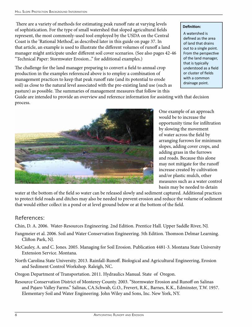
There are a variety of methods for estimating peak runoff rate at varying levels of sophistication. For the type of small watershed that sloped agricultural fields represent,themostcommonly-usedtoolemployedbytheUSDAontheCentralCoastisthe‘RationalMethod’,asdescribedlaterinthisguideonpage37.Inthat article, an example is used to illustrate the different volumes of runoff a land managermightanticipateunderdifferentsoilcoverscenarios.(Seealsopages42-46“TechnicalPaper:StormwaterErosion...”foradditionalexamples.)
The challenge for the land manager preparing to convert a field to annual crop production in the examples referenced above is to employ a combination of management practices to keep that peak runoff rate (and its potential to erode soil) as close to the natural level associated with the pre-existing land use (such as pasture) as possible. The summaries of management measures that follow in this Guide are intended to provide an overview and reference information for assisting with that decision process.
One example of an approach would be to increase the opportunity time for infiltration by slowing the movement of water across the field by arranging furrows for minimum slopes, adding cover crops, and adding grass in the furrows and roads. Because this alone may not mitigate for the runoff increase created by cultivation and/orplasticmulch,othermeasures such as a water control basin may be needed to detain
water at the bottom of the field so water can be released slowly and sediment captured. Additional practices to protect field roads and ditches may also be needed to prevent erosion and reduce the volume of sediment that would either collect in a pond or at level ground below or at the bottom of the field.
References:Chin,D.A.2006.Water-ResourcesEngineering.2ndEdition.PrenticeHall.UpperSaddleRiver,NJ.Fangmeieretal.2006.SoilandWaterConservationEngineering.5thEdition.ThomsonDelmarLearning.
CliftonPark,NJ.McCauley,A.andC.Jones.2005.ManagingforSoilErosion.Publication4481-3.MontanaStateUniversity
ExtensionService.Montana.NorthCarolinaStateUniversity.2013.Rainfall-Runoff.BiologicalandAgriculturalEngineering,Erosion
andSedimentControlWorkshop.Raleigh,NC.OregonDepartmentofTransportation.2011.HydraulicsManual.StateofOregon.ResourceConservationDistrictofMontereyCounty.2003.“StormwaterErosionandRunoffonSalinas
andPajaroValleyFarms.”Salinas,CA.Schwab,G.O.,Frevert,R.K.,Barnes,K.K.,Edminster,T.W.1957.ElementarySoilandWaterEngineering.JohnWileyandSons,Inc.NewYork,NY.
Definition:
A watershed is defined as the area of land that drains out to a single point. From the perspective of the land manager, that is typically understood as a field or cluster of fields with a common drainage point.
Hillslope ManageMent practices guide 7
prevenTinG runoff aT The sourCe
The 4-D FormulaWhenconsideringyouroptionsforrunoffmanagementatanysite,thekeymodesofactionaretoDecrease(volumeandvelocity),Detain,Dissipate,andDivert.Whenatallpossible,diversionshouldbetheactionoflastresort,asdivertingthewatermaysimplybe‘diverting’theproblemandnottreatingit.Thepracticesinthis guide are arranged accordingly.
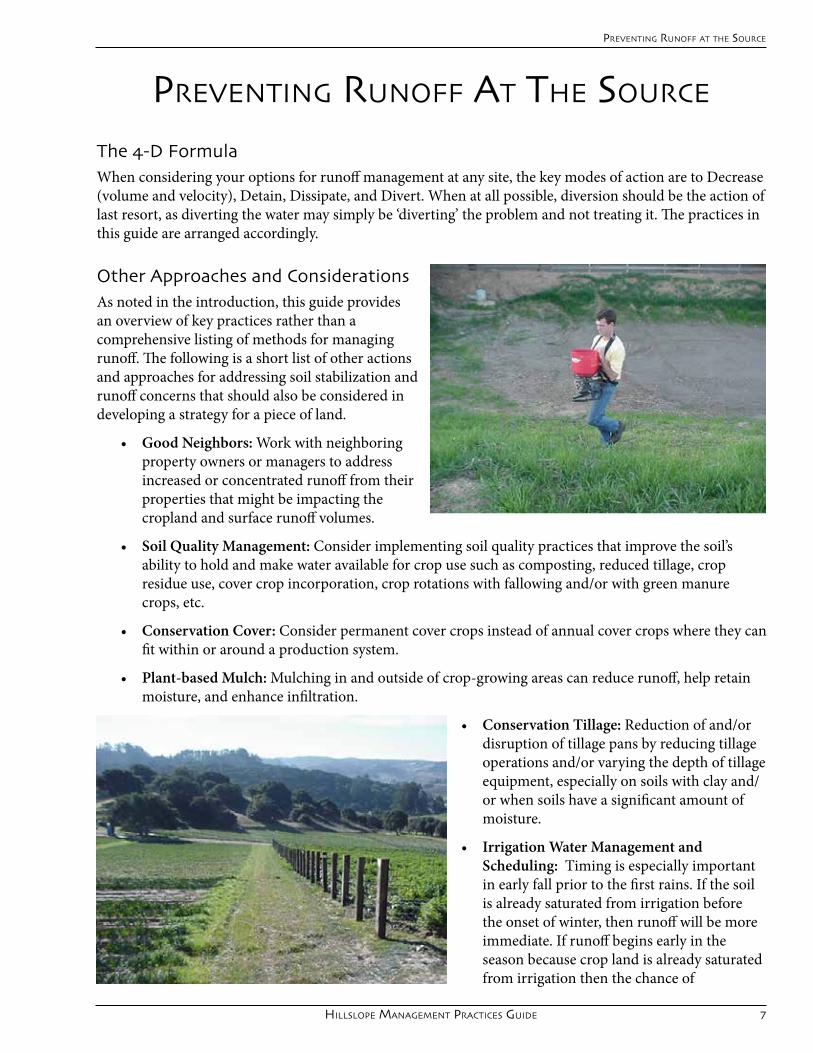
Other Approaches and ConsiderationsAs noted in the introduction, this guide provides an overview of key practices rather than a comprehensive listing of methods for managing runoff. The following is a short list of other actions and approaches for addressing soil stabilization and runoff concerns that should also be considered in developing a strategy for a piece of land.
• Good Neighbors: Workwithneighboringproperty owners or managers to address increased or concentrated runoff from their properties that might be impacting the cropland and surface runoff volumes.
• Soil Quality Management: Consider implementing soil quality practices that improve the soil’s ability to hold and make water available for crop use such as composting, reduced tillage, crop residueuse,covercropincorporation,croprotationswithfallowingand/orwithgreenmanurecrops, etc.
• Conservation Cover: Consider permanent cover crops instead of annual cover crops where they can fit within or around a production system.
• Plant-based Mulch: Mulching in and outside of crop-growing areas can reduce runoff, help retain moisture, and enhance infiltration.
• Conservation Tillage:Reductionofand/ordisruption of tillage pans by reducing tillage operationsand/orvaryingthedepthoftillageequipment,especiallyonsoilswithclayand/or when soils have a significant amount of moisture.
• Irrigation Water Management and Scheduling: Timing is especially important in early fall prior to the first rains. If the soil is already saturated from irrigation before the onset of winter, then runoff will be more immediate. If runoff begins early in the season because crop land is already saturated from irrigation then the chance of
prevenTinG runoff aT The sourCe

8 prevenTinG runoff aT The sourCe
hillslope proTeCTion aT The sourCe
soil erosion is higher because cover crops and other grass related practices are still trying to get established and are less effective.
• Crop and Variety Selection:Sometimeschangingthecroporeventhevarietycanhaveaprofoundeffect on the amount of runoff coming from the field, or it can affect the timing or practices (such as plasticcover)thatinfluencerunoff.
• Other’ Low-tech’ Practices:Strawwattles,mulchstrips,rollingdips,andprotectingexistingbuffervegetationcanhelpslowrunoffandreduceconcentrationsofflowwhereneeded.
References:Casale,Richard,CPESC#3.2013.PersonalCommunication.USDANRCSDistrictConservationist,
Capitola, CA

Hillslope ManageMent practices guide 9
row arranGemenT
keepinG soil and waTer on The field
Description and BenefitsGently sloped furrows help the water to soak into the soil. The water that leaves thefieldflowsslowly,leavingthesoilinplace.
Benefits of row arrangement include: more uniform irrigation, fertigation and drip fumigation; less ponding of water in furrows; ease of harvest; professional looking fields; and reduced erosion control and clean-up expenses.
When Row Arrangement can help your situationThe goal in row arrangement is to make the furrows as close to level as possible without causing water topondinthefurrow.Agoodtargettoshootforis1.5%to2%slopedrows,butslopescloserto.15%canbemoredesirablewithoutcausingponding.Avoidslopessteeperthan4%or5%.Rowarrangementis a technique that requires practice and experience to master, and for some parcels it can be difficult to achieve low slope furrows throughout the block. Other considerations are soil type and existing hard pans that may create sloughing of the beds. Flat furrows are not a problem unless water collects in them which can damage beds or crops. Modify these methods as needed to best fit the land you farm and your own methods of listing beds.
Implementation Tools needed• Instruments that measure slope, such as an abney level, clinometer or hand level•Leveling rod or pole with foot markings•Measuring tape or wheel•Several hundred feet of string (depending upon block length and width)•Wooden stakes or small sacks with sand
ApproachMake a map of the field and the furrow line slope measurements as you take them. This map will help you make decisions about how to lay out the furrows and adjust the guide line for best results.
Step 1: Block layout and planning.• Determinetheideallocationsforyourroads
and planting block boundaries. In general, place roads in the highest and lowest parts of the field, namely, along to tops of ridges

10 row arranGemenT
manaGemenT praCTiCes
and bottoms of swales or draws.• Donotdirectwatertoroadsthatcannothandleit,andplantoincorporateappropriatemethodsof
drainage management along field roads that carry water, as described later in this Guide.• Planforditchesoryourrowarrangementtodirectwaterawayfromheavilytraveledroads.
Otherwise, direct traffic away from roads that cannot be kept dry. • Leavesteepareasandthosethatcarrysubstantialwaterinnaturalvegetation.
Step 2: Lay out the guide line. The guide line marks the alignment of the furrows for the entire block. • Gotothelargest,mostdifficultpartoftheblock(e.g.withthemostuneventerrain)tolayoutthe
guide line .• Setoutalinewithmaximum1.5%to2%slopeusinganinstrumentformeasuringslope(seerelated
fact sheet), marking that guide line with paper bags or stakes.
Step 3: Copy the guide line both up and down the block to mark furrow lines.• Todothis,onepersonstandsateachbagorstake,holdingastringtightlybetweenthem.Each
person uses a measuring wheel or tape to walk 100’ or 200’ uphill to the next place where the furrow slope is to be checked. The distance will be determined by how complicated the slope of the block is. As they walk at the same speed, the string between them remains taught, which helps them stay the same distance apart. A compass can be useful for confirming the exact alignment of the previous furrow checked.
• Now,Checktheslopeofthenewfurrowline.Ifthefurrowlineislessthan4%andhasnolowpoints that will pond, then mark the line and continue to move uphill and lay out furrow lines until the top half of the block is complete.
• Gobacktotheguidelineandmeasuredownhilltolayoutadditionalfurrowlines.Ifanyofthefurrowlinesaresteeperthan4%orhavelowpointsthatwillpond,thengobacktoguideline,adjustit,andrepeatsteps1through4.Don’tforgettocheckatvariouspointsthroughoutthefurrowto
Row Arrangement Figure A: Laying Guidelines

Hillslope ManageMent practices guide 11
identifylowpointsorhighpointsthatwillpondorchangethedirectionoftheflowrespectively.• Ifthefurrowsintheblockcannotbearrangedsothatallarelessthan4%,alignthefurrowsso
thatthesteepestonesareatthebottomoftheblock,wherethefastflowingwaterwilldotheleastamount of damage.
ChallengesIf a field has a low spot that collects water (Fig. B), possible options are to:
• Curvethefurrowtodrainthelowarea;• Dividetheblockintwobyputtingaroadthrough
the low spot; • DrainthemwithoneinchPVCpipestoafurrow
that will carry water out to a road; • Uselandlevelingtofilllowareaofblockand
eliminate ponding.
If the slope of the block changes so that the furrows become too steep (Fig. E), a solution could be to add point rows to compensate (Fig. F).
References:ResourceConservationDistrictsandNRCSofSantaCruzandMontereyCounties.2003.Brochure:“Furrow
Alignment.”http://www.rcdmonterey.org/pdf/FINALEnglishFurrow.pdf.Accessed10/4/13.USDA-NRCS.2008.Field Office Technical Guide.ConservationPracticeStandard.RowArrangement.Code557.Davis,
CA.
Row Arrangement Figure C: Curved Furrow
Row Arrangement Figure E: furrows are too steep
Row Arrangement Figure B: Low spot
Row Arrangement: Curved Furrows
Row Arrangement Figure F: With Point Rows
keepinG soil and waTer on The field

12
row arranGemenT
manaGemenT praCTiCes

Hillslope ManageMent practices guide 13
hoop house anChor row proTeCTion
keepinG soil and waTer on The field
Description and Benefits
Plastic hoophouses as used on the Central Coast provide valuable production benefits and a challenge for runoff management, especially on sloped lands. As conventionally configured, plastic covers can reduce the available permeable surface of a field’s production areabyover90%,dramaticallyincreasingthe volume of water likely to run off a field in a storm event. Also, rainfall impact on the soil is concentrated along the roof edges of hoophouse anchor (or ‘post’’)rows.Methodsthathavebeenused to address these challenges range from soil armoring and cover crops on anchor rows, weather-responsive placementofplasticcovers,gutteranddrainsystemsfordivertinganddirecting‘roof ’runoff,andincreasedspacings between hoophouse rows at intervals planted with grass or other vegetative cover. Filter fabric and cover crops in these rows provide the additional benefit of weed suppression.
When to use Hoop House Anchor Row ProtectionIf a land manager anticipates a field set with
hoophouses will experience rainfall while the plastic sheeting is up, anchor row protections will protectthesoilfrom‘dripline’impacts,reducingmaintenance and erosion risks along anchor rows. The degree to which these measures can be taken will depend on the land manager’s resources, the acreage and density of hoophouses to be placed, the erosive potential of the field (soil texture and slope), the number of acres draining to individual collection points, and the manager’s capacity to
manage accumulated runoff through the field and at the field bottom (or low, collection point).
Implementation ThereisverylittleguidancecurrentlyavailableregardinghoophouserunoffmanagementintheUnitedStates.Hoophousemanufacturersanduniversityextensionguidancedocumentsunderstandablyfocusalmost exclusively on crop production factors. That said, for small, semi-permanent structures there are gutter systems available (Figure C., next page), although we have not observed them adapted for the predominant style of hoophouses in use for large-scale production on the Central Coast. Other novel approaches for using in-field drain-pipe to manage drainage of runoff collected along anchor rows are under investigation by growers but not yet verified in terms of effectiveness in a production context.
Hoop house Figure A: Filter fabric along roofline
Hoop house Figure B: Anchor-row barley cover crop
Ole
g D
augo
vish
i, U
CCE
Vent
ura

14 hoop house anChor row proTeCTion
manaGemenT praCTiCes
WhileUSDANRCSprovidesrunoffmanagementguidelinesforthe‘hightunnel’ (hoophouse) practice, it is intended forapplicationonlessthan10%ofagiven farm’s acreage. Those guidelines are incorporated into this section
Whensettinganchorrows,minimizevehicle traffic if possible in the anchor furrow to maintain maximum infiltration capacity.
Armoring can be made with a permeable material such as filter fabric, straw or fiber mulch or crushed rock (only for permanent installations). The outlet of each anchor row should be further armored to protect
from erosion of collected runoff water as it spills into thefieldendditchorroad.See“DitchPlasticandGrassforRoadProtection”(page27)and“UndergroundOutlets”(page33)fortreatmentstoprotectroadsandditchescarryingwaterofffield.Wherepossible,drainanchor rows to lightly sloped, densely vegetated areas.
TheCaliforniaStorm-waterBMPHandbookrecommends covering the soil surface with geotextiles to reduce erosion from rainfall impact and hold soil in place.Wovenandnonwovenmaterialswithminimumtensilestrengthof80lbscanbeusedinanchorrows.The materials must be resistant to degradation by
ultraviolet(UV)radiation(70%retainedafter500hours)andtobiologicalandchemicalenvironments normally found in soils. Geotextile mats should extend at least 2 feet under the anchor rows and cover the length of the hoophouse. The mat must be secured in place with wire staples and the ends and sidesshouldbeanchoredina6in.deepby6in. wide trench (Figure D). Backfill the trench and tamp the earth firmly to secure the mat.
UCCooperativeExtensionresearchersinVentura County are still investigating the runoff and sediment attenuation benefits of grass cover crops planted along hoophouse post rows, but their preliminary results indicated a definitely observable benefit. Depending on the type of hoophouse
or cover, any increase in the spacing between houses with the addition of vegetated cover will have a corresponding benefit in erosion and runoff reduction. Any such spacing should be made to accommodate mowing or weed trimming, depending upon the scale of the operation. In the example shown to the left,
Hoop house Figure C: Gutter drains to tank
Hoop house Figure D: Geotextile Anchor Trench
Ole
g D
augo
vish
i, U
CCE
Vent
ura

Hillslope ManageMent practices guide 15
thehoophouse‘buffers’arealsotiedintoafielddrainagesystem.The inclusion of buffers or gaps between houses is dependent upon professional consultation, the limitations of hoophouse construction or form, the need relative to slope and soil type, and crop production needs. The Rational Method, as described earlier in this Manual, could potentially be very useful for gauging potential runoff rates of different arrangements of hoophouses for the sake of field planning relative to the site’s capacity for handling that runoff.
ResourcesBaslerandDaugovish.‘UCintroducesanewwaytomanageweedsincaneberrygrowingtunnels.’VenturaCountyBlog.
8/2/2013.http://ucanr.org/blogs/blogcore/postdetail.cfm?postnum=11040CaliforniaStormwaterQualityAssociation.2003.California Stormwater BMP Handbook Construction. Menlo Park, CA.USDA-NRCS.2012.Field Office Technical Guide.ConservationPracticeStandard.SeasonalHighTunnelsforCrops.
Code798.Davis,CA.USDA-NRCS.2011.Field Office Technical Guide.ConservationPracticeStandard.LinedWaterwayorOutlet.Code468.
Davis, CA.
Cover crop planted along hoopehouse post rows by Wayne Gularte
keepinG soil and waTer on The field

16
manaGemenT praCTiCes
hoop house anChor row proTeCTion

Hillslope ManageMent practices guide 17
Cover Crops
Description and Benefits Cover crops as used in perennial and annual cropping systems are associated with soil benefits such as improved tilth and fertility, reduced erosion and crusting, runoff reduction, and increased water-holding capacity. Cover crops can also host beneficial insects and suppress weeds. A specific application of furrow cover crops has been shown to provide significant reduction in runoff in sloped strawberry and vegetable production fields on the Central Coast.
A variety of perennial and annual grasses and broadleaved plants can be used for cover crops as either single- species or multi-species mixes depending on the farmer’s needs. Fast-growing grass species provide high biomass for boosting organic matter in the soil, while some species of legumes can provide high volumes of nitrogen for the following
cash crop. Mixed cover crops can be used to provide a combination of biomass and crop nutrient production. Low-staturedgrassesarelikelybestforfurrowcovercropapplications.“Greenmanure”covercropsaretypicallyincorporated into the soil before a cash crop is planted. In a multi-year crop setting, many annual cover crops can be managed to self-seed, minimizing needs for replanting and soil disturbance. Perennial grass cover crops can provide basic soil cover, and are typically selected to minimize water and sunlight competition with adjacent trees and vines.
When to use Cover CropsCover cropping is useful in a variety of agronomic situations where either rainfall or adequate irrigation are available. Furrow cover crops are helpful on sloped strawberry fields if seeded at the time of transplanting to take advantage of winter rains and crop establishment irrigations.
Implementation Ideal planting time is mid-October to allow for germination and maximum plant growth before soil and air temperatures cool down as fall progresses. Before a cover crop is planted, a suitable seedbed should be prepared. This is usually started after the post-harvest irrigation for perennial crops or after seedbed preparation for annual crops. On farmland, light disking or some other form of tillage is usually sufficient formostcovercrops.Diskingshouldbefollowedbysomesmoothingoperationsuchasfloatingorplaningso that larger clods are broken and the seedbed is smooth. This is particularly important for smaller seeded cover crops such as clovers.
Unlessnon-leguminousorgrass-onlycovercropsareused,additionalfertilizerisnotusuallyrequiredforcover crops. Otherwise, follow your seed company representative’s recommendation for fertilizer type and
keepinG soil and waTer on The field

18 Cover Crops
manaGemenT praCTiCes
rate. Excess nitrogen fertilizer may actually reduce overall nitrogen fixation and give weedy species a competitive edge.Prior to planting, mixes including large-seeded legumes should be inoculated with the appropriate rhizobial bacteria. Host-specificbacteriaworkincombinationwithspecialrootstructurestobindor‘fix’nitrogenintoplanttissues.Someseed is sold pre-inoculated, but large-seeded legumes such as vetch, peas and beans should be inoculated immediately beforeplantingatarateofabout8oz.ofinoculumper100lb. of seed and layering it into the planter hopper. If the seed is broadcast rather than drilled, it should be wet-inoculated to provide better adhesion of the inoculum to the seed.For planting, the cover crop seed can be broadcast or drilled in. Drilling may require less ground preparation, and is the method of choice for first-time plantings. For single species or larger seeded types, an alfalfa drill can be used. Broadcasting seed is faster and less expensive, but will require a light harrowing toincorporatetheseedfollowedbyafinalfloatingorrollingtofinishtheseedbed.Inestablishedperennialcover crops, supplemental seeding may be needed every two to five years. On sloped ground, an application of straw over newly-seeded ground can provide temporary slope protection until the cover crop germinates and grows large enough to provide substantial cover. If fall rains are not expected immediately, a light irrigation will settle soil around the seed and hasten germination. Summerannualcovercropswillrequireregularirrigationsjustasanyotherwarmseasoncrop.
Table 1. Suggested Grasses and Seeding Rates
Seed Varieties
Life Cycle & Planting Time
Grass Characteristics
Lbs. of seed per 100 ft. by 10 ft. of roadway
Lbs. of seed per
acre
Estimated cost per
acre for seed
*Cereal Rye “Merced” Variety Secale cereal *Don’t confuse cereal rye with annual rye Lolium multiflorum, potentially an invasive weed
Annual
early season
Sept-Nov.
Good on dry, sandy slopes, excellent roots
2 80 52 (a)
Common Barley “UC 937” Variety Hordeum vulgare
Annual late season Nov. & Dec.
or for emergencies
Good on all soils, fair roots
4.5 180 63 (b)
Trios “102” Tricale
Annual early season Sept. -Nov.
Good on all soils, good roots & low growth pattern
1.5 60 57 (c)
California Brome Bromus carinatus (nurse crop, fast germ. rate, short lived - 3 yrs.) Creeping wild rye Leymus triticoides (long lived, slow germ. rate)
Perennial Native Mix
early season Sept. & Oct.
Good on dry, sandy slopes, good roots Good on dry sandy slopes, and loam/clay soils, excellent roots
0.3
1
25
25
174 (d)
750 (e)
Hillslope ManageMent practices guide 19
(a) Pricebasedon$52/80lbbag,SnowSeedCo.,August2013(b) Pricebasedon$17.50/50lbbagof“UC937”Barley,SnowSeedCo.,August2013(c) Pricebasedon$47.50/50lbbagoforganicallygrowntriticale,SnowSeedCo.,August2013(d) ThispriceisbasedonablendofCaliforniabrome,meadowbarleyandbluewildrye:$7.65/1.1lb
inquantitiesover50,HarmonyFarmSupply,August2013.(e) PriceforL.triticoidescanbe$20-$40/lb.ormoredependingontheyearandthesource.
MaintenanceIn annual crop fields, the cover crop height can be maintained with line trimmers or mowers, and the covercrop‘knockeddown’withherbicideormowingbyFebruaryorMarchtonotinterferewithcashcrop production. If self-seeding is desired, mowing should be delayed until the cover crop has matured seed.Whenmowingacovercropmixthatincludeslegumes,careshouldbetakentonotcutbelowthegrowing point, or re-growth will be hindered. Mowing, spot-spraying or hand-hoeing may be needed to keep sprinkler or drip emitters clear, but using low-growing cover crops or extending sprinkler risers could reduce the need for such maintenance.Incorporation of the cover crop (if necessary) should be timed to allow at least two weeks of decomposition in the soil before planting. Timing of incorporation should also be made in consideration of adequate soil moisture for decomposition, otherwise additional irrigation may be necessary to adequately break down the organic matter for proper seedbed preparation for the following crop. In spring, care must also be taken not to enter a field with excessive soil moisture, which would obviously hinder equipment access and also damage the soil with excessive compaction and clodding. The simplest scenario for cover crop incorporationinvolves“knockingdown”thecovercropwitheithermowingorherbicide,followedbydisking the plant material into the soil. After a period of decomposition, the soil surface would then be reshaped and smoothed, as needed.
ReferencesIngels,C.1995.Cover Crop Selection and Management in Orchards and Vineyards. UCDavisSustainableAgriculture
Research and Education Program. Davis, CA.USDA-NRCS.LockefordPlantMaterialCenter.ConservationPlantReleases.http://plant-materials.nrcs.usda.gov/
capmc/releases.htmlRobins,P.,R.BresnickHolmes,andK.Laddish,ed. 2001. Bring Farm Edges Back to Life! 5thedition.YoloCounty
Resource Conservation District.
keepinG soil and waTer on The field

20 Cover Crops
manaGemenT praCTiCes

Hillslope ManageMent practices guide 21
keepinG soil and waTer on The field
veGeTaTed filTer sTrips
Description and Benefits A filter strip is an area of grass or other permanent vegetation used to “filter”sediment,organics,nutrients,pesticides, and other contaminants fromfarmsheetflowrunoffinorder to maintain or improve water quality in local waterbodies, such as streams and ponds. Filter strips slow the velocity of water, allowing the settling out of suspended soil particles, infiltration of runoff and soluble pollutants, adsorption of pollutants on soil and plant surfaces, and plant uptake of soluble pollutants. Filter strips are typically no narrower than twelve feet, and increased width typically increases the filtering or water quality benefit. Filter strips can be an aesthetic means of stabilizing field border soil and can also serve as forage (on-farm use or cash crop), turnrows and headlands, and field access. Filter strips can enhance wildlife objectives depending on the vegetative species used and managementpracticed.Whenplantedwithnativeoradaptedvegetativespeciestheycanprovidefoodandcover for important wildlife.
When to use Vegetated Filter StripsFilter strips are most effective and useful on land with less than10%slopeattheloweredgeofcropfields,sacrificeareas, or hardened footing areas where there is sheet or uniformshallowflow,especiallyadjacenttostreams,ponds, lakes, and drainageways. They can also serve as part of a riparian forest buffer system.
Implementation • The filter strip should be designed to accommodate
anticipatedflows,slopeandsoiltypetomaximizethe potential benefit. To determine the optimum widthofafilterstrip,consultwithanNRCSengineerwho will evaluate the individual site.
• Beforeafilterstripisplanted,asuitableseedbedshouldbeprepared.Onfarmland,lightdiskingor some other form of tillage is usually sufficient. Disking should be followed by some smoothing operationsuchasfloatingorplaningsothatlargerclodsarebrokenandtheseedbedissmooth.Thisisparticularly important for smaller seeded species such as clovers.
• Fornon-leguminousorgrass-onlyplantings,additionalfertilizermaybeneededtoaidestablishment.
22 veGeTaTed filTer sTrips
manaGemenT praCTiCes
Fertilize and amend the soil according to soil test results from the site and the needs of the species to be planted. Excess nitrogen fertilizer can be washed or leached out of the site (causing a water quality concern) or even give weedy species a competitive edge over the planted species.
• Iflegumesaretobeincludedintheplanting,makesurethattheyareeitherpre-inoculatedorthatyouinoculatethemwiththeappropriaterhizobialbacteriapriortoplantingatarateofabout8oz.ofinoculum per 100 lb. of seed.
• Forplanting,thefilterstripseedcanbebroadcastordrilledin.Drillingmayrequirelessgroundpreparation, and is the most desirable planting method. For single species or larger seeded types, an alfalfa or legume drill can be used. Broadcasting seed is faster and less expensive, but will require a lightharrowingtoincorporatetheseedfollowedbyafinalfloatingorrollingtofinishtheseedbed.If necessary, mulch the newly-seeded area with straw for soil protection during germination. Supplementalseedingmaybeneededevery2-5years.
• Iffallrainsarenotexpectedimmediately,alightirrigationwillsettlesoilaroundtheseedandhastengermination.
• Mow(andharvestifpossible)filterstripgrassesseveraltimesayeartoencouragedensevegetativegrowth. For ground nesting wildlife, care should be taken to avoid mowing during nesting periods. If self-seeding is desired, mowing should be delayed until the desired filter strip species have matured seed.Whenmowingaplantingthatincludeslegumes,careshouldbetakentonotcutbelowthegrowing point, or re-growth will be hindered.
• Becarefultomaintainoriginalwidthanddepthoftheplantedareainordertomaintaintheintendedbenefitsofthefilterstrip.Inspectandrepairafterstormeventstofillingullies,removeflowdisruptingdebris and sediment accumulation, reseed disturbed areas, and take other measures to prevent concentratedflowinthefilterstrip.
• Suppressweedswithwell-timedmowings,whicharepreferabletoherbicideinafilterstrip.Ifherbicideis needed, it should be applied at low rates or in spot treatments and with adequate time for degradation before anticipated storms or irrigations (runoff events).
• Takecaretoexcludelivestockandvehiculartrafficfromthefilterstripduringwetperiodsoftheyearsince filter strips rely on infiltration for reducing contaminants. It is recommended that this type of traffic be excluded at all times to the extent that is practical.
• Restorationofthefilterstripwillberequiredonceithasaccumulatedsomuchsedimentthatitisnolonger effective.
ReferencesUSDA-NRCS.2011.FieldOfficeTechnicalGuide.ConservationPracticeStandard.FilterStrips.Code393.Sacramento,
CA.Robins,P.,R.BresnickHolmes,andK.Laddish,ed. 2001. Bring Farm Edges Back to Life! 5thedition.YoloCounty
Resource Conservation District.
This article is not intended to replace professional advice. Before implementing this practice, consult a professional to ensure the best outcome for your application

Hillslope ManageMent practices guide 23
road seedinG
Temporary praCTiCes To ConTrol erosion
Description and BenefitsRoads are some of the most vulnerable areas onthefarmforerosion.Withafewsimpletechniques, your roads can be protected. Seedinggrassonwinterroadsprovidesalargeroot mass that protects roads from washing out, protects bed ends from slumping, inhibits the growth of weeds, and enhances the water quality of runoff into adjacent streams.
Road seeding is a good idea when you are working with sloped farmlands with roads running directly downslope between planting blocks that that capture and transport winter runoff downslope.
Implementation Before laying out or modifying your road, evaluate the key areas of the farm that will either drain to or receive runoff from your road. If possible, redirect uphill runoff to a sediment basin or to a well-protected road. Protect non-cropped areas with vegetation such as a cover crop or perennialgrasses.Wherefurrowsconveyheavystormrunoff,consider modifying them by creating longer furrow blocks withshallower(1-3%)slopestoslowdowntherateofrunoffreachingyourroad.(See‘RowArrangement’)Furrowsandplastic mulch on beds concentrate and speed up run off of
winter rains. Manage that water before it reaches your roads.In general, if you are laying out field on raw ground, look at the natural low spots in the field and place roads there. Then arrange your planting blocks and furrows according to the drainage that those roads can handle.Forroadswithprotectionsuchasundergroundpipesystems,flowcanbecollectedfromblocksoneithersideoftheroad(FigA).However,forroadswithminimalprotectionsuchasgrassandplastic-linedditches(Fig.B),abetterapproachistobreakupthatflowbyorientingfurrowstodrainadjacentblockstoindividual roads or ditches.
Figure A. Figure B.

24 road seedinG
manaGemenT praCTiCes
Ifaroadissteeperthan20%,runofffromthefurrowblocksshouldbespreadoutevenlytolesssteeproads.If those areas carry a lot of runoff, the road design should include a reinforced channel as described in a later section of this Guide.Aroadcanbeconfiguredtocarrysomewaterbyeithershapingitasabroad‘v’(asdescribedbelow)orwithaditchalongalowside(orbothsides)usingplastictoprotector‘armor’it,aspicturedonthepriorpage.Thelattermethodisdescribedin“DitchPlastic&GrassforSteepRoadProtection”onpage27.
Steps for shaping a road with a broad channel in the center to protect bed ends from erosion:1. Cultivate fields and chisel if necessary to increase water infiltration.2. Cutroadswithscrapertoformagentle“V”shape,6”deepincenter.3. Spreadsoilinlowpartsoffield.4. Listbedsacrossroads.5. Cutroadsagainwithscrapertoformagentle“V”shape.6. Useleftoversoiltomakewaterbarsorshapebeds;don’tleaveitontheroad.7. Roadsattheedgeofafarmcanbeslopedouttonaturalvegetation
Fall Grass Planting on roads to Minimize Winter ErosionPlant grasses as soon as roads are cut and irrigate if necessary. If soil on the road is compacted, lightly aerate the soil with a disk, chisel or a rake. (Passing over the soil with a ring shank roller prepares an excellent seed bed.) Broadcast seed over the road by hand or with a seed broadcaster. If you were to throw a baseball cap over the seeds, you should see ten seeds below the hat (see chart for detailed application rates on p. x). Seedmoreheavilyaroundendsofbedsandseedatleast10feetintoeachfurrow(See‘CoverCrops’forinformation on full-furrow seeding).Lightlyburyseedabout1/2inchdeepinsoilbypassingoveritwithadiskorrake.Covertheseedwithstraw mulch to protect it and retain moisture, and provide supplemental irrigation if planted before rains. Afterthegrassisgrown,mowgrassbeforeseedsset.Keepvehiclesoffroadsduringwintertoavoidtiretrack creating gullies.The tables below indicate the maximum number of farmed acres that can be safely drained with grass alone to stop road erosion depending on road slope, use of annual or perennial grasses, and presence or absence of full bed plastic mulch in winter.

Hillslope ManageMent practices guide 25
Maximum number of acres that grassed roads can handle:
Withplasticmulchedbeds:
Annual Grass Perennial Grass
Withoutplasticbedmulch:
Annual Grass Perennial Grass
Usethesetablesaboveasaguidetoestimatetheuppermostportionofyourroadsthatcanbeprotectedwith grass alone and still drain safely. Below these sections, incorporate a ditch or pipeline the rest of the way down your grassed road. In situations with a large amount of water that comes from non-cropped areas, you will be safer to extend the ditch or pipe all the way up the road
Benefits and limitations of annual vs. perennial grasses for road cover
ReferencesResourceConservationDistrictsandNRCSofSantaCruzandMontereyCounties.Controlling Erosion on Hillside Farm
Roads.http://www.rcdmonterey.org/pdf/FINALEnglishRoadsBrochure0301.pdfAccessed10/4/2013.
.
Temporary praCTiCes To ConTrol erosion

26 road seedinG
manaGemenT praCTiCes

Hillslope ManageMent practices guide 27
diTCh plasTiC and Grass To proTeCT
sTeep roads from erosion
Description and BenefitsOn steep fields with ditches and roads that run directly down slope with potential to carry highly-erosive runoff during winter rains, one form of temporary protection for the ditch or road is a channel reinforced withplastic.Whilethisprotectstheconveyance from erosion, it must have a protected outlet or pond to be able to handlethoseflowsatthebottomoftheslope.See“UndergroundOutlets”(page33) for slopes needing more significant conveyancecapacityor“SedimentandWaterRetentionBasins”(page35)forbottom of slope runoff management.
When to use Ditch Plastic and GrassIt is best to consult a qualified professional and an experienced land manager with specific knowledge of a given ranch to assess whether plastic and grass seed will be sufficient to protect a particular road or ditch, andtodeterminetheappropriatetreatmentformanagingtheoutflowofthatditch.Thetablesonpagexxofthe previous article are an additional helpful reference for estimating when grass alone may not be adequate to stabilize a road.
Implementation
Afterroadsarecutandsmoothed,cuta1’deepx4’wideditchinthecenterorsideoftheroad.(Ditchesoneither side of a rode have also been used effectively.)
Layout2milembossedplasticor6milsmoothplasticformaximumstrength.Bothcanwithstandadeerstepping on them without tearing. Don’t reuse plastic from other applications.
Setplasticinashingle-style,startingfromthebottomofthehillandworkyourwayup.sothatthebottom
Temporary praCTiCes To ConTrol erosion
Figure A. Cross-section of plastic road ditch looking ‘up road’.
28
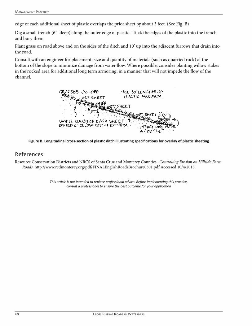
edgeofeachadditionalsheetofplasticoverlapsthepriorsheetbyabout3feet.(SeeFig.B)
Digasmalltrench(6”deep)alongtheouteredgeofplastic.Tucktheedgesoftheplasticintothetrenchand bury them.Plant grass on road above and on the sides of the ditch and 10’ up into the adjacent furrows that drain into the road.Consult with an engineer for placement, size and quantity of materials (such as quarried rock) at the bottomoftheslopetominimizedamagefromwaterflow.Wherepossible,considerplantingwillowstakesintherockedareaforadditionallongtermarmoring,inamannerthatwillnotimpedetheflowofthechannel.
ReferencesResourceConservationDistrictsandNRCSofSantaCruzandMontereyCounties.Controlling Erosion on Hillside Farm
Roads.http://www.rcdmonterey.org/pdf/FINALEnglishRoadsBrochure0301.pdfAccessed10/4/2013.
Cross rippinG roads & waTerbars
manaGemenT praCTiCes
Figure B. Longitudinal cross-section of plastic ditch illustrating specifications for overlay of plastic sheeting
This article is not intended to replace professional advice. Before implementing this practice, consult a professional to ensure the best outcome for your application

Hillslope ManageMent practices guide 29
Cross-rippinG roads & waTerbars
Description and Benefits A water bar can be used to help redirect water from roads on steep slopes towards structures or lands that can carry or absorb the water safely with minimal erosion. Cross-ripping is a technique that temporarily increases the road’s ability to absorb runoff by creating fissures perpendicular to the slope for water to pass into the subsoil.
When to Cross-Rip roads and place WaterbarsTemporary water bars and cross-ripping are helpful as quick and inexpensive supplemental practices to road seeding when more permanent structures (ditches and underground outlets) are not feasible. Waterbarscanalsobeusedtodirectroadsurfaceflowtoexistingdrainagestructuresorheavilyvegetatedareas.
Implementation Waterbarsareusedprimarilywhena road will not receive traffic for the winter or for an extended period of time. Vehicular traffic should be minimized and the water bars should be seeded and fertilized to reduce erosion. A water bar is constructed by excavating a troughata30-45degreeangledownslope across the road. The excavated earth should be piled on the downhill side of the water bar. To be sure that no water by-passes the water bar, the uphill end of the
water bar should be tied in to any ditches or furrows. The water bar should have a protected outlet on its downhill end to allow water to be directed safely to an appropriately armored ditch, underground outlet, or naturally-vegetated area (of limited slope).Spacingofwaterbarsshouldbedeterminedwiththeguidanceofaqualifiedprofessional,althoughgeneralguidance for water bar spacing on established unpaved roads can be helpful as a reference. The table below isanexampleofsucharesourcefromtheUCANRRuralRoadsConstructionandMaintenanceGuide.Itis important to note that such information is intended for permanent roads and may assume standard road
Temporary praCTiCes To ConTrol erosion
Table. Water bar spacing recommendations for unpaved roads from Kocher, Gerstein, and Harris. 2007. as adapted from Keller and Sherar 2003. For this table, 'erosive soils' are those with high concentrations of silt or fine sands relative to clay content.

30 Cross-rippinG roads & waTerbars
manaGemenT praCTiCes
construction methods such as gravelling and compaction.
ReferencesKeller,G.,andSherar,J.2003.Low Volume Roads Engineering: Best Management Practices Field Guide. USDAForest
Service/USAID.Kocher,Gerstein,andHarris.2007.Rural Roads. A Construction and Maintenance Guide for California Landowners.
UniversityofCaliforniaDANR.Publication8262.Davis,CA.ResourceConservationDistrictsandNRCSofSantaCruzandMontereyCounties.Controlling Erosion on Hillside Farm
Roads,http://www.rcdmonterey.org/pdf/FINALEnglishRoadsBrochure0301.pdfAccessed10/4/2013.
This article is not intended to replace professional advice. Before implementing this practice, consult a professional to ensure the best outcome for your application

Hillslope ManageMent practices guide 31
Temporary praCTiCes To ConTrol erosion
Temporary slope drain
Description and Benefits Atemporaryslopedrainisaflexiblepipethat runs overland and is designed to carry concentrated runoff from the top of a slope to the base of the slope without causing erosion. Runoff is intercepted upslope of a disturbed area and is routed to the slope drain, which carries the runoff to a stable outlet, where it is released at a non-erosive velocity into a sediment trap or basin. Whileitissimplerandquickertoinstallatemporary slope drain than an underground outlet, it only functions with a single inlet at its uppermost point.
When to use Temporary Slope DrainsTemporary slope drains may be a short-term alternative drainage management tool for fields with limited tenure and dramatic runoff management needs. Temporary slope drains are applicable on sites with a maximum drainage area of 10 acres and on slopes 3 percent or steeper that have not yet been stabilized. Largerareasshouldhaverunoffsplitbetweenmultipledrains.Thispracticeisusedinconjunctionwithseveral other BMPs such as temporary diversions, stone outlet protection, and sediment traps and basins. Always consult a qualified professional for proper application of this technique
Implementation The slope drain may be a rigidpipe,flexibleplasticcorrugated pipe or even layflathosewithsecure,watertight joints and a flaredinletportion.Thesize of the pipe will vary depending upon the drainage area of the site, but should not have a diameter that exceeds 30 inches. To prevent failure of the device during large storm events, the soil surrounding the pipe must
be hand compacted, with the portion of the diversion or berm above the pipe at least one foot higher than the height or diameter of the pipe.
To prevent erosion of the diversion structure, the inlet of the slope drain should be underlain with geotextile filter fabric. The type of filter fabric that is selected will vary upon the individual characteristics
32
ofthesite,butshouldextendatleast5feetfromtheinlet,withtheedgeskeyedatleast6inchesintotheground.
The pipe should be anchored to the slope according to the manufacturer’s installation instructions. However,regardlessofthemodelselected,itmustbesecuredtotheslopewithgrommetsinatleast2placesspacednomorethan10feetapart.Atthebaseoftheslope,aminimumof4feetofpipeshouldhaveslopeof1%orflatterbeforedischarginginordertoreducethevelocityoftherunoff.Theslopedrainshouldoutlet to a protected surface and a sediment trap or basin
MaintenanceSlopedrainsshouldbeinspectedaftereachrainfallevent.Inspectoutletsforerosionanddownstreamscour. If eroded, repair damage and install additional energy dissipation measures. If downstream scour isoccurring,itmaybenecessarytoreduceflowsbeingdischargedintothechannel.Inspecttheinletforcloggingandundercuttingandremovedebrisfrominlettomaintainflows.Torepairanyundercutting,itmaybenecessarytoinstallaflaredsectionorripraparoundtheinlet.
ReferencesCaliforniaStormwaterQualityAssociation.California Stormwater BMP Handbook.‘EC-11:SlopeDrains’.2007.DaneCountLandandWaterResourcesDepartment.2007.Dane County Erosion Control and Stormwater Management
Manual.SlopeDrain(Temporary).Madison,WI.Minnesota Pollution Control Agency. 2000. Protecting Water Quality in Urban Areas, A Manual.St.Paul,MN.U.S.D.A.NaturalResourcesConservationService.1996.National Catalog of Erosion and Sediment Control and Storm
Water Management. Guidelines for Community Assistance.Washington,D.C.U.S.D.ANaturalResourcesConservationServiceandMississippiDepartmentofEnvironmentalQuality.April1994.
Planning and Design Manual for the Control of Erosion, Sediment, and Stormwater.Washington,D.C.USDA-NRCS.2011.Field Office Technical Guide.ConservationPracticeStandard.SurfaceDrain,MainorLateral.Code
608.Sacramento,CA.USDA-NRCS.2011.Field Office Technical Guide. ConservationPracticeStandard.Pipeline.Code516.Sacramento,CA.
Temporary slope drain
manaGemenT praCTiCes
This article is not intended to replace professional advice. Before implementing this practice, consult a professional to ensure the best outcome for your application

Hillslope ManageMent practices guide 33
underGround ouTleTs
Description and Benefits Stormwaterthatreachesyourfarmroadscanbe directed into an underground outlet (or pipe) and transferred down the slope without taking sediment and crops along with it. An underground outlet generally needs to be coupled with a sediment basin at its outlet to effectively handlethehighflowvolumesthatundergroundoutlets are designed to accommodate. An inadequate downstream conveyance can result in extremeerosion,sedimentationand/orflooding.Whentheconcentratedwaterconveyedbytheunderground outlet are caught in a sediment basin,theoutflowofwatercanbemeteredoutgradually. This system is a permanent and highly effective solution.
When to use Underground OutletsUndergroundoutletsarecost-effectiveinsettingswithapermanentfieldconfigurationandshouldonlybe planned and implemented with guidance from a qualified professional. In general, such pipelines and theirinletsareplacedunderneathpermanentroadsrunningthrough‘low’collectionareasonslopesteepenough to generate high concentrated runoff volumes. An underground outlet should be designed with a safe downstream outlet.
Implementation The design capacity of the underground outlet is based on the requirements of the structure or practice it serves. The capacity of the underground outlet for natural or constructed basins needs to be adequate for the intended purpose without causing inundation, damage to crops, vegetation, or works of improvements. Undergroundoutletsmaybedesignedforeitherpressureorgravityflow.
Inlet An inlet can be a collection box, a perforated riser, or other appropriate device. For perforated risers, use durable, structurally sound material that is resistant to damage by rodents or other animals. Inlets need
permanenT sTruCTures To manaGe sedimenT and runoff

34 underGround ouTleT
manaGemenT praCTiCes
an appropriate trash guard to ensure that trash or other debris entering the inlet passes through the conduit without plugging.
Designcollectionboxeslargeenoughtoallowmaintenanceandcleaningoperations.Useblindinletswherethe installation of an open or above ground structure is impractical. Design the blind inlet with a graded granular filter around the conduit. Design the filter based on the particle size of the surrounding soil and thedesiredflowrate.
Materials Plastic, concrete, aluminum, and steel pipe shall meet the requirements specified in the applicable ASTMstandard.Materialsmustmeetapplicablesitespecificdesignrequirementsforleakage,externalloading,internalpressureorvacuum.Undergroundoutletconduitscanbeperforatedornonperforated,dependingonthedesignrequirements.Useafilterfabricwrap(sock)orappropriatelydesignedgranularfilter if migration of soil particles into the conduit is anticipated. Design the filter based on the particle size of the surrounding soil to prevent rapid clogging of the filter. Protect all exposed plastic materials from degradation due to exposure to sunlight.
Outlet The outlet must be stable for anticipated designflowconditionsfromtheundergroundoutlet. Design the underground outlet for water surface conditions at the outlet expected during thedesignflowconditions.Theoutletmustconsistof a continuous 10 foot section or longer of closed conduit or a headwall at the outlet. If a closed conduit is used, the material must be durable and strong enough to withstand anticipated loads, including those caused by ice. Do not design outlets to be placedinareasofactiveerosion.Usefireresistantmaterials if fire is an expected hazard. All outlets must have animal guards to prevent the entry of rodents or other animals. Design animal guards to
allow passage of debris while blocking the entry of animals that cannot easily escape from the conduit.
Operation And MaintenanceA written operation and maintenance plan needs to address the following minimum requirements:• Periodicinspections,especiallyimmediatelyfollowingsignificantrunoffevents,tokeepinginlets,trash
guards,andcollectionboxesandstructurescleanandfreeofmaterialsthatcanreduceflow• Promptrepairorreplacementofdamagedcomponents• Repairorreplacementofinletsdamagedbyfarmequipment• Repairofleaksandbrokenorcrushedlinestoinsureproperfunctioningoftheconduit• Periodiccheckingoftheoutletandanimalguardstoensureproperfunctioning• Repairoferodedareasatthepipeoutlet• Maintenanceofadequatebackfillovertheconduit• Tomaintainthepermeabilityofsurfacematerialsonblindinlets,periodicscouringorremovaland
replacement of the surface soil layer may be necessary
ReferencesUSDA-NRCS.2012.Field Office Technical Guide.ConservationPracticeStandard.UndergroundOutlet.Code620.
Sacramento,CAThis article is not intended to replace professional advice. Before implementing this practice,
consult a professional to ensure the best outcome for your application
Hillslope ManageMent practices guide 35
sedimenT and sTormwaTer ConTrol basins
Description and BenefitsStormwaterflowsareoftensointensethattheyoverwhelmon-farmdrainagesystemsandfloodintopublicditches,drainsandroads.Thesehighflowsofwater can carry large amounts of soil which increase riskoffloodinganddamagetotheaffectedfarmanddownslope lands. Detention basins help reduce the volume, intensity, and sediment load of storm water runoff by slowing the water down, allowing more water to infiltrate, drop out most of the sediment load and cause water leaving the field to be cleaner, slower, and lower volume.
When to use Sediment and Water Control BasinsA detention basin can be effective when placed at the low end of a field in which runoff has been collected by ditches and underground outlets, and where the potential intensity or volume of that runoff will overwhelm downstream structures. A basin constructed solely for sediment management is generally designed for smaller capacity than a stormwater control basin. Do not construct them in stream channels or other permanent water bodies.
ImplementationA stormwater detention or sediment basin should be designed and developed in consultation with a qualified engineer to ensure the stability and function of the berm or dike and outlet structures. A basin and its outlet must be correctly sized for sufficient
capacity to accommodate the anticipated rate and volume of runoff so that the outlet is not overwhelmed whilereducinganddelayingtheflowoutofthestructuretodownstreampropertiesorwaterways.An overwhelmed structure will eventually fail, posing a liability in terms of safety, maintenance, and environmental impacts. The capacity of the sediment basin shall equal the volume of sediment expected to be trapped at the site during the planned useful life or intended maintenance interval of the basin or the improvements it is designed to protect. To reduce construction costs and save space, most basins are designed to be cleared out annually.
permanenT sTruCTures To manaGe sedimenT and runoff

36 sedimenT and sTormwaTer ConTrol basins
manaGemenT praCTiCes
One example of a convenient location for siting a basin is inside the field road at or around the low corner of a field using the road embankment has a berm, provided that it is (or can be) adequately laid and compacted in lifts (or layers) to ensure stability. The sides of the berm or embankment are can be further protected from erosion if covered with vegetation or armored with rock (depending upon the intensity of flowexerteduponthesite).
Thefirststepindesigningabasinistodeterminetheanticipatedpeakflowofrunoffanddesiredoutflowrates.Whileaskilledlandmanagerwithyearsofexperienceonagivenranchmightbeabletoanticipatethis, such information is best generated with the assistance of a qualified engineer. A brief description of this process is provided at the beginning of this Guide.
Critical design features of any basin should include:
1. A protected inlet to prevent bank erosion when water enters the pond.
2. A carefully sized and anchored outlet pipe (see “Principal SpillwayDesign”onpage40).Outletscanbebeslottedpipeorflashboardrisers.Whileaflashboardriserismoreexpensive,itallowsmoreflexibilityforsettingwaterleveloroutletflows.Withaslottedpiperiser,thewaterisallowedtogradually exit the basin through slots in the side of the pipe. If runoff increases then the water exits through the top of the pipe. Pipelines should be designed with a minimum velocity of1.4ft/sectopreventsedimentfromcollectinginsidethepipe(CPS620).Thepipeshouldhaveananti-seepcollartoprevent‘piping’orseepagefromdegradingthecompactedfillsurrounding the outlet pipe. The riser should be anchored in concrete. Anti-seep collars are often made of concrete or sheet metal with mastic coating. If an anti-seep collar is not installed, saturated conditions will gradually cause the berm to fail.
3. A berm and excavated area with adequate capacity for the desired volumewithatleastonefootofbermheight(‘freeboard’)above the top of the outlet pipe riser. Berm and basin bank slopes should not exceed 2:1 if they are constructed of compacted soil. In general, anyfillshouldbecarefullycompactedinlayersor‘lifts’oflessthan x”foridealstabilityandtominimizepotentialerosionoftheslope.
4.Anemergencyspillwayisaportionofthebermthatislowerthan the majority of the berm and appropriately armored with rock or concrete to withstand the erosive force of the water cascading over anddownit.Thisisa‘failsafe’featuretoprotecttheprimarywater
retention structure so that under maximum runoff conditions (those that exceed the pipe outlet capacity), water will exit through the secondary or emergency spillway rather than over the top of the berm.
References:USDA-NRCS.2010.Field Office Technical Guide.ConservationPracticeStandard.SedimentBasin.Sacramento.CA.USDA-NRCS.2009.Field Office Technical Guide.ConservationPracticeStandard.WaterandSedimentControlBasin.
Code638.Sacramento,CA.
This article is not intended to replace professional advice. Before implementing this practice, consult a professional to ensure the best outcome for your application

Hillslope ManageMent practices guide 37
esTimaTinG peak runoff usinG The “raTional meThod”
A simplified tool that engineers and hydrologists use to predict the watershed peak runoff rate is known as‘TheRationalMethod’.Aprojectdesignerhastoknowthepeakrunoff(Qp)rateinordertoproperlydesign channels, culverts, slope drains, and sediment basins. The Rational Method is a simple formula often referred to as the Rational formula:
Qp = CiA
WhereQpisthepeakrunoffincubicfeetpersecond(cfs),Cistherunoffcoefficient(definedfurtherbelow),“i”isthedesign(oranticipated peak) rainfall intensity in inches per hour, and A is the watershed area in acres. The Rational Method should be limited to areas smaller than 200 acres, where the entire area is contributing to the runoff to be managed. The information presented in this section is intended for educational purpose and not for the design of erosion control structures. Each farm should be evaluated by a professional engineer prior to the design and installation of structures to control runoff and erosion.
The watershed characteristics that affect the peak runoff rate are incorporated in the runoff coefficient (C). The runoff coefficient varies between 0.0 and 1.0 depending on the watershed soil’s infiltration rate, thelanduse,thelandcoverandthelandslope.Soilswithrapidinfiltrationrates,suchassands,havelowrunoff coefficients (eg. 0.0 to 0.30), while soils with slow infiltration rates, such as clays have much higher runoff coefficients. Impermeable areas such as those covered with pavement, buildings or plastic have runoffcoefficientsof1.00ornearly1.00.Theinfluenceofvegetationoninfiltrationrateistwo-fold.First,the denser and larger the vegetative cover, the more rain will be intercepted and not reach the soil surface. Second,thepresenceofdeep-rootedvegetationtendstoimprovesoilstructureandincreaseinfiltration.Typical runoff coefficients are shown on Table 1, below. It is common practice to use the fraction of impervious area of a watershed as an estimate of runoff coefficient. For example, plastic mulch and roofs will have a larger fraction of impervious area compared to pasture and woodlands.
Therainfallintensity,”i”,intheRationalMethodisoftenreferredtoasthe‘design’rainfallintensity,whichisthe uniform rainfall intensity that has duration equal to the watershed’s response time (or the time it would take during a runoff event for a droplet of water to travel from the top of the watershed to the collection
manaGemenT informaTion: esTimaTinG peak runoff usinG The “raTional meThod”
1 cfs = 449 gallons per minute
Table 1. Rational Method Runoff Coefficients

38 esTimaTinG peak runoff usinG The “raTional meThod”
manaGemenT resourCes
pointatthebottom:the‘timeofconcentration’).Thisdesignrainfallintensityisafunctionofthreeparameters: (1) the watershed’s time of concentration, (2) the watershed’s location and (3) the return period (storm frequency) for which the peak runoff rate is desired. To determine the design rainfall intensity for use in the Rational Method, first determine the watershed’s time of concentration, tc which is based on the watershed or field length, cover and slope. For example, fields with a larger fraction of impermeable area (i.e.plasticmulch)willhaveafasterrunoff(shallowconcentrated)flowvelocityandashortertraveltimeortimeofconcentration.Second,determinethereturnperiod(orstormfrequency)forwhichyouwantto anticipate maximum runoff. (In this context, the less frequent or likely a storm, the larger it will be. Dependingonthelevelofrunoff‘protection’youneed,thatcouldbefora10-yearor100-yearstorm‘returnperiod’.)Third, read the design rainfall intensity from the best available Intensity-Duration-Frequency (IDF) information to determine the design rainfall intensity for the rainfall duration and return period. The NOAANationalWeatherServicehasapublicwebsitethatprovidesthisinformationathttp://hdsc.nws.noaa.gov/hdsc/pfds/.
Thelandcoverwillinfluencethepeakrunoffintwoways.First,thetimeofconcentrationwillbesmallerforareaswithalargerimperviousfraction,whichdirectlyinfluencesthestormintensity.Second,therunoffcoefficient will be larger for areas with a larger impervious fraction. This dual effect will produce a larger peakrunoffforareaswithlargerimperviousfraction(Table2).TheunitsofpeakflowpresentedinTable2areincubicfeetpersecondperacre(cfs/ac)ofland.Thepeakrunoffincubicfeetpersecondcanbeeasilycalculatedbymultiplyingthepeakflowperunitarea(cfs/acre)bythefarmacreage.
For example, we will compare the peak runoff rate for three scenarios: a row-cropped farm with and without plastic mulch and that of native pasture land in the same location (Table 3). The runoff coefficient (C), based on the same farm area, slope and soil, is larger for the row crop production than the native pasture(Table1),andlargerwithplastic-mulchedthanwithoutit.Theplasticmulch(C=0.60)willreducethe amount of water that can infiltrate into the soil, thus increasing the proportion of the rainfall that willrunofffromthefield.Thetimeofconcentrationwillbealotshorterinthecroppedfield(tc=5&10 minutes) than in the native pasture because a large proportion of the area is covered by plastic and the presence of furrows allows faster movement of water in the field. Because a shorter tc corresponds with a higher potential rainfall intensity, based on a 10 year storm frequency, the factor for rainfall intensity will becorrespondinglylargerforthecultivatedlandthanthelandinpasture.UsingtheRationalMethodinthis example, then, estimates that the peak storm runoff will be three to twelve times greater for the row cropped land (without and with plastic mulch, respectively) as compared to the native pasture land.
Table 2. Peak Runoff influenced by Time of Concentration (tc) and Runoff Coefficient (C).
Hillslope ManageMent practices guide 39
ReferencesChin,D.A.2006.Water-ResourcesEngineering.2ndEdition.PrenticeHall.UpperSaddleRiver,NJ.NorthCarolinaStateUniversity.2013.Rainfall-Runoff.BiologicalandAgriculturalEngineering,ErosionandSediment
ControlWorkshop.Raleigh,NC.OregonDepartmentofTransportation.2011.HydraulicsManual.StateofOregon.
Table 3. Example Calculation of the Storm Peak Runoff Rate
manaGemenT informaTion: esTimaTinG peak runoff usinG The “raTional meThod”

40
prinCipal spillway desiGn for a waTer ConTrol basin
Step 1: Peak Runoff Rate EstimationThe peak runoff rate will be influencedbytheslope,soils,and percent of impermeable area. Based on the results in Runoff Table3 in the previousarticle(page39)andpastNRCSprojects,thecommonpeakrunoffis1.5cfs/acrefora10-yrfrequencystorm on cultivated hillslope lands of Northern Monterey County.
Step 2: Principal Spillway Riser SizingBasedonthepeakrunoffdeterminedinStep1andTableA1,determinethesizeofthepiperiser.FortheexampleshowninRunoffTable3onpage39,thepeakflowrateis25cfsandthepiperisersizeselectedis36”.Thetopoftherisershouldhaveatrashracktopreventdebrisfromcloggingthestructure.
Step 3:Anti-flotation Block SizingTheamountofconcreteneededfortheanti-flotationblockispresentedinTableA1anddependsonthediameter of the riser pipe. The riser should be securely fastened to the block by placing two bars through it and embedded within the concrete block.
manaGemenT resourCes
Table A1. Discharge Table for a Corrugated Metal Pipe Riser (Head= 1.0 ft) and Size of Concrete Required for Anti-floatation Block.
prinCipal spillway desiGn fpr a waTer ConTrol basin
Spillway Figure A: Configuration of discharge holes on outlet pipe.

Hillslope ManageMent practices guide 41
praCTiCe informaTion: prinCipal spillway desiGn for a waTer ConTrol basin
Step 4: Principal Spillway Barrel SizingIt is recommended that the pipe barrel size be equal to or one size smaller than the pipe riser size.Based on thepeakrunoffdeterminedinStep1andTableA2,determinethesizeofthepipebarrel.FortheexampleshowninRunoffTable3(page39),thepeakflowrateis25cfs,sotheappropriatepipebarrelsizeshouldbe30”.
Step 5: Multiple-Orifice Outlet Riser SizingThe number and size of the orifices will depend on the drainage area (Table A3). The surface area of the basinwascalculatedusing3600ft3/acreofdrainageareaandaveragedepthof6’.Theorificeswillbelocatedin the riser evenly distributed on two columns and separated vertically by 3 times the hole diameter and 120degreeshorizontally(seeFigure.A,previouspage).Theorificesaredesignedtodrainthebasinin24hrs.
References:CaliforniaStormwaterQualityAssociation.2003.California Stormwater BMP Handbook Construction. Menlo Park, CA CityofKnoxville.2001. Knoxville BMP Manual Erosion and Sediment.SedimentBasin.Knoxville,TN.USDA-NRCS.January2012.Engineering Field Handbook.Chapter6-Structures.WashingtonD.C.USDA-NRCS.2010.Field Office Technical Guide.ConservationPracticeStandard.SedimentBasin.Code350.
Sacramento.CA
Table A2. Discharge Table for a Corrugated Metal Pipe Barrel Flowing Full with a Head of 5.0 ft (K = 1, L = 70 ft).
Table A3. Hole Size Required to Drain Basin within 24 hours

42
Resource Conservation District
of Monterey County 744 La Guardia St., Bldg. A Salinas, California, 93905 (831) 424-1036 ext-124
Page 1/5
TECHNICAL PAPER
STORMWATER EROSION AND RUNOFF ON SALINAS AND PAJARO VALLEY FARMS PURPOSE The purpose of this document is to characterize the typical rates of stormwater runoff and soil erosion under different cropping patterns for Salinas and Pajaro valley farms.
METHODS Peak and total runoff rates were calculated using the hydrology model presented in the Natural Resources Conservation Service Engineering Field Manual, Chapter 2, which was calibrated using limited field data collected locally during storms. Erosion estimates were made based on field measurements made by the Natural Resources Conservation Service, the Resource Conservation Districts of Monterey County and Santa Cruz County, and the California State University at Monterey Bay in addition to calculations using the Unified Soil Loss Equation modified to include concentrated channel erosion. Input parameters were selected based on historic rainfall data, typical soil types and farm sizes.
LIMITS OF THIS ANALYSIS This paper is intended for general educational purposes and not for design. Farm facilities including ditches, sediment basins and pipes should be designed on an individual basis. Using the values presented here for design may result in massive erosion, flooding, dam failure, injury and death. Each farm should be evaluated by a professional engineer prior to the design and installation of structures to control water or sediment. The Resource Conservation District of Monterey County and the Natural Resources Conservation Service offer this service free of charge, and capable local engineering businesses are available as well.
The analysis presented here is based on specific hypothetical examples. We discourage extrapolating this information beyond these examples. Each farm is unique and should be evaluated on an individual basis. The combination of soil management, soil type and cropping pattern can increase or decrease runoff and erosion rates substantially. Two farms that appear similar to the untrained observer can vary in their runoff and erosion rates by several hundred percent.
This analysis is based on mathematical models that, while calibrated to observed conditions on Central Coast farms, contain numerous assumptions and simplifications. As such, the full range of conditions is not examined here. Typical values are provided as a general indication of how much runoff and erosion can be expected from different types of land management.
This document is intended to be informational purposes and not intended to promote or guide any regulation on land use restriction. The variability between farms is an important reason why this data should not be used for such purposes.
EXAMPLE FARM BLOCK The farm block considered for this analysis was 10 acres, square and sloped at four percent. For the case of a strawberry field with full bed plastic mulch, 50 percent of the soil surface was assumed to be covered with plastic. A strawberry field without plastic mulch will behave similarly to the vegetable crop case. For the hoop houses, 80 percent of the soil surface was assumed to be covered with plastic. In all cases it was assumed that runoff flows off the farm down roads or through ditches. Spreading runoff water over large flat areas reduces peak runoff and erosion rates. (Such areas are typically unavailable as they are used for production.)
manaGemenT resourCes
sTormwaTer erosion and runoff on salinas and pajaro valley farms

Hillslope ManageMent practices guide 43
Resource Conservation District
of Monterey County 744 La Guardia St., Bldg. A Salinas, California, 93905 (831) 424-1036 ext-124
Page 2/5
With respect to runoff rates, it is assumed that no practices have been used to increase infiltration, such as incorporating organic material into the soil, chiseling, or planting cover crops in furrows, on farm roads or in other areas. These practices may reduce runoff rates significantly.
RESULTS: RUNOFF RATES Table 1 presents approximate stormwater runoff rates, reported as cubic feet per second (cfs), resulting from different agricultural operations. There is a wide spectrum of runoff rates for different types of crop cover. Undisturbed soil with perennial pasture cover infiltrates large quantities of water, resulting in very low runoff rates. Both soil covered with plastic and bare soil are effectively sealed to infiltration, resulting in substantial increases to runoff rates. (Rain impact on bare soil rapidly clogs soil pores.)
The increase factor presented in table 1 relates the cropping situation to pasture. An increase factor of five indicates that the peak runoff rate of the cropping situation is five times that of pasture. The increase factor is the highest for frequent storms because most of the rain associated with these smaller storms will infiltrate in a pasture setting while some runoff will be generated on cropland.
While the percent increase in runoff between certain types of irrigated agriculture and pasture is high, whether that amount of runoff poses a problem depends largely on the capacity and erodibility of downstream ditches, culverts and channels. If those channels have sufficient capacity, the excess runoff may not be a problem. If the channels lack sufficient capacity, flooding or downstream erosion will result. Downstream erosion is discussed in the following section. Water that infiltrates into the soil leaches salts, is available to plants and can recharge groundwater if geologic conditions permit. Runoff is less available for groundwater recharge unless it is captured and detained for infiltration.
Many parts of these two valleys have heavier soils such as clays and clay loams. These soils will yield more runoff under all conditions, including pasture. The runoff increase factor for these soils will be less than for sandy soils.
To help interpret these results, table 2 shows the capacity of culverts of different sizes. In order to estimate the cumulative impacts of more than one farm block, additional analysis is required. Generally, as the total acreage increases the peak runoff per acre decreases.
RESULTS: EROSION Field erosion is affected by many factors, including the amount of soil protected from rainfall by plants, mulch or other covers, and the amount of runoff, which is largely determined by soil texture and management related to permeability. Steeper slopes, longer runs and areas of more intense rainfall will generally also have more erosion. This analysis is limited to sandy loam soils. Heavier soils are generally less erosive. While fields partially covered with plastic have less area exposed to rainfall, the runoff rate is much higher than for fields without plastic and this generally causes the overall erosion rate to be higher.
The Soil Surveys of the US Department of Agriculture, Soil Conservation Service lists rates of erosion that are tolerable from the perspective of maintaining long term crop production. Those rates typically range from two to five tons per acre per year. Erosion at these rates is nearly invisible. Field erosion averaging 1/16th of an inch in depth amounts to 11 tons per acre. Tolerable rates of erosion with respect to maintaining channel capacity and other beneficial uses of receiving waters have not been determined for our area. Similarly, site specific assessments are required to determine the amount of increased runoff that can be accommodated by existing channels and ditches without excessive erosion.
TeChniCal paper: runoff on salinas and pajaro valley farms

44
manaGemenT resourCes
sTormwaTer erosion and runoff on salinas and pajaro valley farms
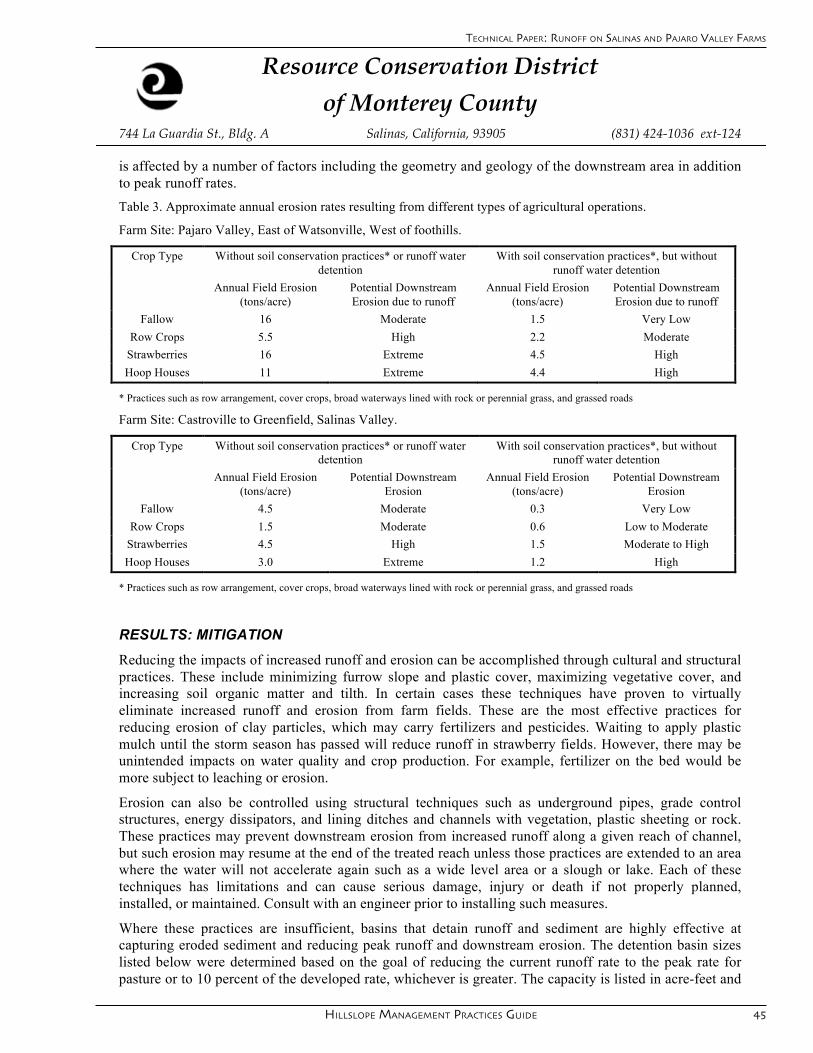
Hillslope ManageMent practices guide 45
Resource Conservation District
of Monterey County 744 La Guardia St., Bldg. A Salinas, California, 93905 (831) 424-1036 ext-124
Page 4/5
is affected by a number of factors including the geometry and geology of the downstream area in addition to peak runoff rates.
Table 3. Approximate annual erosion rates resulting from different types of agricultural operations.
Farm Site: Pajaro Valley, East of Watsonville, West of foothills.
Crop Type Without soil conservation practices* or runoff water detention
With soil conservation practices*, but without runoff water detention
Annual Field Erosion (tons/acre)
Potential Downstream Erosion due to runoff
Annual Field Erosion (tons/acre)
Potential Downstream Erosion due to runoff
Fallow 16 Moderate 1.5 Very Low
Row Crops 5.5 High 2.2 Moderate
Strawberries 16 Extreme 4.5 High
Hoop Houses 11 Extreme 4.4 High
* Practices such as row arrangement, cover crops, broad waterways lined with rock or perennial grass, and grassed roads
Farm Site: Castroville to Greenfield, Salinas Valley.
Crop Type Without soil conservation practices* or runoff water detention
With soil conservation practices*, but without runoff water detention
Annual Field Erosion (tons/acre)
Potential Downstream Erosion
Annual Field Erosion (tons/acre)
Potential Downstream Erosion
Fallow 4.5 Moderate 0.3 Very Low
Row Crops 1.5 Moderate 0.6 Low to Moderate
Strawberries 4.5 High 1.5 Moderate to High
Hoop Houses 3.0 Extreme 1.2 High
* Practices such as row arrangement, cover crops, broad waterways lined with rock or perennial grass, and grassed roads
RESULTS: MITIGATION Reducing the impacts of increased runoff and erosion can be accomplished through cultural and structural practices. These include minimizing furrow slope and plastic cover, maximizing vegetative cover, and increasing soil organic matter and tilth. In certain cases these techniques have proven to virtually eliminate increased runoff and erosion from farm fields. These are the most effective practices for reducing erosion of clay particles, which may carry fertilizers and pesticides. Waiting to apply plastic mulch until the storm season has passed will reduce runoff in strawberry fields. However, there may be unintended impacts on water quality and crop production. For example, fertilizer on the bed would be more subject to leaching or erosion.
Erosion can also be controlled using structural techniques such as underground pipes, grade control structures, energy dissipators, and lining ditches and channels with vegetation, plastic sheeting or rock. These practices may prevent downstream erosion from increased runoff along a given reach of channel, but such erosion may resume at the end of the treated reach unless those practices are extended to an area where the water will not accelerate again such as a wide level area or a slough or lake. Each of these techniques has limitations and can cause serious damage, injury or death if not properly planned, installed, or maintained. Consult with an engineer prior to installing such measures.
Where these practices are insufficient, basins that detain runoff and sediment are highly effective at capturing eroded sediment and reducing peak runoff and downstream erosion. The detention basin sizes listed below were determined based on the goal of reducing the current runoff rate to the peak rate for pasture or to 10 percent of the developed rate, whichever is greater. The capacity is listed in acre-feet and
TeChniCal paper: runoff on salinas and pajaro valley farms
46
Resource Conservation District
of Monterey County 744 La Guardia St., Bldg. A Salinas, California, 93905 (831) 424-1036 ext-124
Page 5/5
the footprint in square feet, assuming an average basin depth of 4 feet. Actual basin footprint sizes for a given capacity vary widely based on site conditions. Basins of these sizes will be only somewhat effective at retaining clay particles and associated chemicals.
Table 4. Approximate detention storage required to mitigate effects of increased runoff rates.
10 Acre Farm Site: Pajaro Valley, East of Watsonville, West of foothills.
Design Storm Size
Rainfall
Row Crops
Strawberries Hoop Houses
(Year) Inches Acre-Feet Square Feet
Acre-Feet Square Feet
Acre-Feet Square Feet
2 3.5 0.7 8700 1.1 14,000 1.3 16,000
10 4.6 1.0 12,000 1.5 19,000 1.7 21,000
25 6.0 1.5 19,000 2.1 26,000 2.3 29,000
10 Acre Farm Site: Castroville, Salinas, Spreckles
Design Storm Size
Rainfall
Row Crops
Strawberries Hoop Houses
(Year) Inches Acre-Feet Square Feet
Acre-Feet Square Feet
Acre-Feet Square Feet
2 1.6 0.3 3700 0.5 6200 0.6 7500
10 2.5 0.4 5000 0.8 10,000 1.0 12,000
25 3.0 0.5 6200 0.9 11,000 1.1 14,000
CONCLUSIONS Common agricultural land uses have the potential to increase erosion and runoff rates substantially over natural levels in the Pajaro and Salinas Valleys, but common soil conservation practices have the ability to reduce these rates to levels that are sustainable over the long term. Determining acceptable levels of runoff and erosion is a complex and site specific task that is beyond the scope of this analysis. Those levels are likely to be affected more by downstream site conditions than conditions on the farm itself. Despite the potential for increased runoff associated with agricultural land uses, these runoff rates are likely to be substantially lower than urban, industrial or transportation land uses that have higher percentages of impervious surfaces. Similarly, erosion rates for the cropland situations considered here are likely to be much lower than for land uses that result in bare soil or increased runoff on land with slopes over 5 percent. Irrigation that simulates rainfall has to potential to cause erosion in a similar manner to storm events. The intensity of the irrigation is an important factor and is highly variable, therefore such analysis is beyond the scope of this paper.
More information is needed to improve these tables. Specifically, winter runoff data from adjacent fields under different management practices would be helpful to quantify the benefits of non-structural practices that reduce erosion and runoff. Interesting comparisons might include chiseled versus non-chiseled fields, or a field with runoff directed down vegetated roads versus one where runoff flows down earthen ditches, or fields with lots of incorporated organic matter versus ones with little organic matter. If you would like to participate in such a study, please contact the Resource Conservation District of Monterey County. Confidentiality is guaranteed.
manaGemenT resourCes
Hillslope ManageMent practices guide 47
erosion ConTrol seed and planT maTerial sourCes
Erosion Control Seed Sources
CentralCoastWilds 114LibertyStreet,SantaCruz (831)459-0655www.centralcoastwilds.com
L.A.HearneKingCity&Prunedale(831)663-1572www.hearneseed.com
Elkhorn Native Plant Nursery P.O.Box270,MossLanding (831)763-1207http://www.elkhornnursery.com/
Native Revival Nursery8022SoquelDrive,Aptos(831)684-1811
GeneralFeed&Seed 1900Commercial,SantaCruz (831)476-5344http://generalfeedandseed.com/
Rana Creek Ranch35351CarmelValleyRoad,CarmelValley,CA(831)659-4851
SnowSeedCompany21855RosehartWay,Salinas (831)758-9869www.snowseedco.com
Where to Buy Rice Straw
AGCO IncorporatedHollister,CA(831)628-3564
GeneralFeed&Seed1900Commercial,SantaCruz(831)476-5344(minimumpurchase-250balesofricestraw)
L.A.Hearne8525PrunedaleN.Rd.(831)663-1572www.hearneseed.com
Note: Werecommendricestrawbecauseitislessweedy on upland farms.
praCTiCe resourCes: seed and planT maTerial sourCes

48
measurinG slope
Tools to Measure the slope of your fieldsEffective use of many of the techniques in this Guide is dependent on measuring and mapping out the slope ofthelandyou’reworking.Slopecanbemeasuredwithrelativelysimpletoolsandtechniquesasdescribedbelow or can be conducted professionally by engineering and land-leveling contractors. The following are brief descriptions of some of the available instruments that measure slope and how to use them
Abney Level
Anabneylevelmeasuresslope.Lookthroughthe level and aim at an object that is the same height as your eye. For example, if you are one inch taller than your partner, aim at the brim of their hat. Now adjust the abney level until the level bubble is in the center of the view. Then read the percent slope off the side of the instrument.
Clinometer
Aclinometermeasuresslope.Holdtheclinometeruptooneeye,whilekeepingbotheyesopen.Withoneeye,lookatanobjectthatisthesameheightasyoureye.Withtheother eye, look at the clinometer dial to read the slope in percent. A very simple clinometer can also be constructed with a straight rod, protractor, string and a washer. Percent numbers are on the right hand side as you read the clinometer.
Hand Level
Lookingthroughahandlevel,youseeobjectsatthesame elevation as your eye when the bubble is centered. This method can be used by one person alone by pounding a stake into the ground and tying a ribbon toit.Youmustmaketheneededmeasurementstocalculate the slope.
measurinG slope
manaGemenT resourCessu
rvey
ing-
supp
lies.
dunc
an-p
arne
ll.co
m
ww
w.prlog.org
ww
w.fo
rest
ry-s
uppl
iers
.com
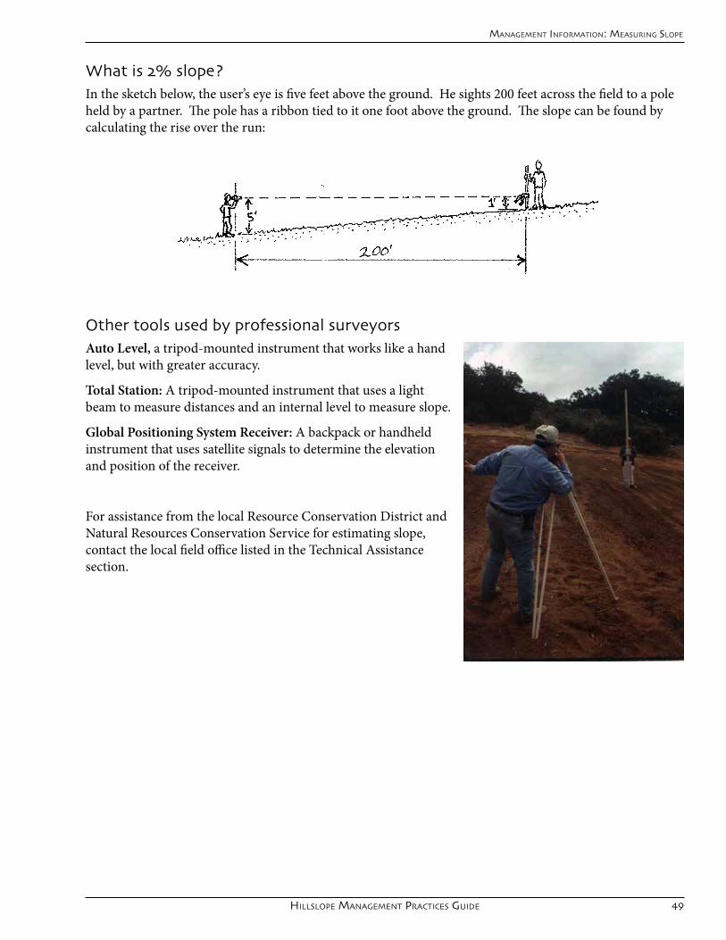
Hillslope ManageMent practices guide 49
manaGemenT informaTion: measurinG slope
What is 2% slope?Inthesketchbelow,theuser’seyeisfivefeetabovetheground.Hesights200feetacrossthefieldtoapoleheld by a partner. The pole has a ribbon tied to it one foot above the ground. The slope can be found by calculating the rise over the run:
Other tools used by professional surveyorsAuto Level, a tripod-mounted instrument that works like a hand level, but with greater accuracy.
Total Station: A tripod-mounted instrument that uses a light beam to measure distances and an internal level to measure slope.
Global Positioning System Receiver: A backpack or handheld instrument that uses satellite signals to determine the elevation and position of the receiver.
For assistance from the local Resource Conservation District and NaturalResourcesConservationServiceforestimatingslope,contact the local field office listed in the Technical Assistance section.

50
TeChniCal assisTanCe supporT
Your local RCDs and NRCS work in partnership to provide conservation technical assistance with staff skilled in soil and water conservation, agricultural engineering, and vegetation management techniques. Depending onfunding cycles, they can also provide partial financial assistance for project implementation.
ResourceConservationDistrictofMontereyCounty 831-424-1036x124
USDANaturalResourcesConservationService,Salinas 831-424-1036x101
ResourceConservationDistrictofSantaCruzCounty 831-424-1036x124
USDANaturalResourcesConservationService,Capitola 831-424-1036x101
UCCE Farm Advisors are a critical resource for local growers on the whole gamut of regional crop productionconcernsandbringwiththemtheresourcesoftheUniversityofCalifornia.Onmattersofsoilandwaterconservation,theyalsoworkcooperativelywiththeRCDsandNRCS.
UniversityofCaliforniaCooperativeExtension,SalinasValley 831-759-7350
UniversityofCaliforniaCooperativeExtension,Watsonville 831-763-8040
The Agricultural Commissioner is responsible for the promotion and protection of the agricultural industry while also ensuring farm worker health and safety, environmental resource protection, and a fair market place for consumers.
MontereyCountyAgriculturalCommissioner 831-759-7325
SantaCruzCountyAgriculturalCommissioner 831-763-8080
manaGemenT resourCes
TeChniCal assisTanCe