hiline vertical stacking fan coils - daikin...
TRANSCRIPT
Catalog 770-17HiLine™
Vertical Stacking Fan CoilsType FHSS and FHSK

CAT 770-17 • VERTICAL STACKED FAN COILS 2 www.DaikinApplied.com
Table of ConTenTs
Table of ConTenTs
Introduction . . . . . . . . . . . . . . . . . . . . . . . . . . . . . . . . . . 3Daikin Applied HiLine™ Fan-Coil Units . . . . . . . . . . 3Nomenclature . . . . . . . . . . . . . . . . . . . . . . . . . . . . . . . 3
Introduction . . . . . . . . . . . . . . . . . . . . . . . . . . . . . . . . . . 4Low CFM design (300 thru 800 CFM) . . . . . . . . . . . . 4
Features and Benefits . . . . . . . . . . . . . . . . . . . . . . . . . 6Design features for high performance and low operating cost . . . . . . . . . . . . . . . . . . . . . . . . 6Optional features and accessories . . . . . . . . . . . . . . . 9
Application Data . . . . . . . . . . . . . . . . . . . . . . . . . . . . . 11Application considerations . . . . . . . . . . . . . . . . . . . . 11
Performance Data . . . . . . . . . . . . . . . . . . . . . . . . . . . . 14Physical Data . . . . . . . . . . . . . . . . . . . . . . . . . . . . . . . 16
Dimensional Data . . . . . . . . . . . . . . . . . . . . . . . . . . . . 18Model FHSS (Basic Unit) Sizes 03 Thru 08 (300 thru 800 CFM) . . . . . . . . . . . 18Model FHSK (Knock-down Unit) Sizes 03 Thru 08 (300 thru 800 CFM) . . . . . . . . . . . 19Riser Location — FHSS and FHSK Unit Sizes 03 Thru 08 (300 thru 800 CFM) . . . . . . . . . . . 20Model FHSS (Basic Unit) Sizes 10 Thru 12 (1000 thru 1200 CFM) . . . . . . . . . 21Riser Location — FHSS Unit Sizes 10 Thru 12 (1000 thru 1200 CFM) . . . . . . . . . 22Riser Location for Master-Slave Units. . . . . . . . . . . . 23
Wiring Diagrams . . . . . . . . . . . . . . . . . . . . . . . . . . . . . 24Engineering Guide Specifications . . . . . . . . . . . . . . 26
Model FHSS (Basic Unit) Sizes 03 thru 08 (300 thru 800 CFM) . . . . . . . . . . . . . .26Unit Sizes 10 & 12 (1000 thru 1200 CFM) . . . . . . . . 27Model FHSK (Knock-down Unit) Sizes 03 Thru 08 (300 Thru 800 CFM) . . . . . . . . . . . 28

InTroduCTIon
www.DaikinApplied.com 3 CAT 770-17 • VERTICAL STACKED FAN COILS
InTroduCTIon
Daikin HiLine™ Fan-Coil Units The Daikin HiLine fan-coil air conditioning units are designed for use in multiple floor apartments, office buildings, hotels and other similar applications and require a minimum amount of floor space. Just one HiLine unit may do the job that formerly required more than one conventional unit.
The results of many years of experience in the development, design and manufacture of fan-coil air conditioners have been incorporated in the Daikin HiLine units to provide highly efficient, quiet performance; individual thermostatic control; simple, low cost installation; application flexibility; and low maintenance and operating costs with no sacrifice in room comfort, design, or appearance.
For the ultimate in design, performance, efficiency, flexibility of application, and ease of installation and maintenance, look to Daikin HiLine fan-coils.
Application flexibility
Two distinct designs are available with the complete flexibility necessary for any application requirement.
• Low CFM design - The 300 through 800 CFM blow-through configuration units are designed to meet individual room control requirements.
• High CFM design - The 1000 and 1200 CFM draw-through configuration units are designed for multiple discharge arrangements so that one unit can serve more than one room.
Both designs are available for two-pipe and four-pipe systems with single, double, triple and top discharge arrangements. Optional equipment is available to provide complete application flexibility.
Contact your Daikin representative for a copy of the Daikin SelectTools™ selection program to choose a unit meeting your needs.
Nomenclature
FHS S 1 03 A A Product Category FHS = Vertical stacking HiLine™ hydronic coil
Product Identifier S = Standard hideaway shipped assembled K = Shipped in 2 pieces
Design Series 1 = Design 1
Nominal CFM 02 = 200 03 = 300 04 = 400 06 = 600 08 = 800 10 = 1,000 12 = 1,200
Voltage A = 115/60/1 J = 265-277/60/1
A = Stand-alone M = Master C = Companion (slave)

CAT 770-17 • VERTICAL STACKED FAN COILS 4 www.DaikinApplied.com
InTroduCTIon
InTroduCTIon
Low CFM design (300 thru 800 CFM) Blow-through units to meet individual room requirementsNeutral unit shown (risers in back) * Ball shut-off valves are not included
with factory valve packages. They are only provided with factory risers.Low Sound Level Operation - The low CFM
design features a quiet, energy efficient motor and fan assembly, carefully located within a fully insulated cabinet to provide low sound level operation.
Risers - Factory cut 104" long. No on-the-job cutting required. Supply and return risers have factory installed sweat ball valves* and are factory insulated
Motor & Fan Assembly - Quiet, energy efficient, permanent split capacitor motors and centrifugal fans for low sound level. Fan housings are of a split type design or have separate inlet rings to allow easy removal of the fan motor.
Removable Chassis - All components are mounted on a single removable chassis so that a different capacity chassis can be installed in the same cabinet should future needs require it.
Coils - High efficiency type for full rated capacity. AHRI certified.
Optional valve packages can be provided for 24V, 115V, and 277V .
Cabinet - Heavy gauge galvanized steel. Fully insulated for quiet operation.
Fast, Simple Installation - Simply stack one unit above the other, sweat the couplings to the risers and connect the power. The unique nonstop slip couplings require only one person for setting and connecting .
Opposite Hand Units - Two adjacent room units can be connected to a single set of risers and still retain individual room temperature control. Twin units must be joined in the field. Reverse piping for same hand units not available.
Filter - Easily accessible by simple removal of return air grille panel.
Return Air Grille Panel - Heavy gauge steel with stamped grille and attractive Antique Ivory finish. Available as an accessory.
Access & Sound Baffle Panel - Insulated galvanized steel. Easily removed for complete access for service.
Controls - Face mounted, plug-in type, combination 3-speed switch and thermostat. Thermostat electrical box is adjustable for wall thickness. No wiring required.
Discharge Arrangements - Single, double, triple and top discharge arrangements are available.

InTroduCTIon
www.DaikinApplied.com 5 CAT 770-17 • VERTICAL STACKED FAN COILS
High CFM design (1000 thru 1200 CFM) For Multiple Discharge Arrangements Specially Designed For High CFM Performance - these draw-through type units are ideal for luxury hotel and condominium type buildings where multiple discharge arrangements with a common return air location, high CFM performance and quiet operation are required.
Neutral unit shown (risers in back)
* Ball shut-off valves are not included with factory valve packages. They are only provided with factory risers.
OPPOSITE HAND UNITS - Two adjacent room units can be connected to a single set of risers and still retain individual room temperature control. Twin units must be joined in the field. Reverse piping for same hand units not available.
Fast, Simple Installation -Simply stack one unit above the other, sweat the couplings to the risers and connect the power. The unique non-stop slip couplings require only one person for setting and connecting.
Motor & Fan Assembly (Not shown) - Quiet, energy efficient, permanent split capacitor motors and centrifugal fans, mounted in the draw-through position with a common return location, provides high CFM performance with low sound levels.
Optional valve packages can be provided for 24V, 115V, and 277V .
Coils - High efficiency type for full rated capacity. ARI certified.
Access & Sound Baffle Panel - Easily removed for complete access to internal controls, motor and fan assembly for service.
Return Air Grille Panel - Heavy gauge steel with stamped grille and attractive Antique Ivory finish.
Controls - Unit-mounted combination 3-speed switch and thermostat. Thermostat electrical box is adjustable for wall thickness. Thermostat wiring required in the field and centrifugal fans, mounted in the draw-through position with a common return air location, provide high CFM performance with low sound level. (optional molex connections can be provided).
Cabinet - Heavy gauge galvanized steel. Fully insulated for quiet operation.
Discharge Arrangements - Single, each unit. Twin units must be joined double, triple and top discharge arrangements in the field. Reverse hand piping for are available. same hand units not available.
Risers (Not shown) - Factory cut 104" long. Supply and return risers are factory insulated. The unique non-stop slip couplings
Sweat Ball Valves* - factory mounted on coil.
Filter - Easily accessible by simple removal of return air grille panel.

CAT 770-17 • VERTICAL STACKED FAN COILS 6 www.DaikinApplied.com
feaTures and benefITs
feaTures and benefITs
Design features for high performance and low operating cost Telescoping Thermostat Box
Plug-in Field Mounted Thermostat
Unit configuration Unit sizes 03 through 08 feature a blow-through design with completely removable chassis. The motor, fan assembly, coil(s), drain pan and valve packages are mounted on a compact chassis which slides out through the return air grille and access panel.
Unit sizes 10 and 12 feature a draw-through design. Filter, drain pan and drain line are accessible by removing the return air grille. Controls, valves, motor and fan assembly are accessible by removing the access panel.
Knock-down unit The FHSK knock-down unit configuration, available for unit sizes 03 through 08, allows installation, leak testing and insulation of the risers and stub-outs prior to the unit placement. Risers can be field provided or factory supplied and shipped to the jobsite before the units. After riser installation, the bottom half of the unit is set in place. Connections are then made to the supply, return and drain risers as well as the power supply. Then the top half of the unit is installed.
Fast, low-cost installation Installation time is minimized by the unit’s design, riser slip couplings, and unit mounted controls. Units are completely factory assembled and wired and have individual thermostat controls. Risers are factory cut to 104" in length and insulated. Optional riser couplings are available. Installation is accomplished by simply stacking the units one above the other floor-by-floor, brazing the couplings and risers together, and connecting the power. Only one person is required for installation because the slip couplings eliminate the requirement for perfect unit alignment with the swaged riser joints of other manufacturers.
Twin units To reduce installed cost, two units of opposite hand on each floor can share a set of supply, return and drain risers. Individual thermostat control is retained by each unit. Units can be placed side-to-side or side-to-back

feaTures and benefITs
www.DaikinApplied.com 7 CAT 770-17 • VERTICAL STACKED FAN COILS
Coils High-capacity, low-flow heating/cooling coils are standard. Separate row heating coils are available for 4-pipe systems. All coils are furnished with manual air vents.
High performance coils Two-pipe system units have a standard low-flow, high capacity cooling/heating coil. Four-pipe system units have a standard low-flow, high capacity cooling coil and a one- row heating coil. All coils are seamless copper tubes in a staggered pattern and feature the patented HI-F rippled and corrugated aluminum fins for high heat transfer efficiency. Full depth collars are drawn in the fin stock for accurate control of fin spacing and completely cover the copper tubes to lengthen coil life. Copper tubes are mechanically expanded into the fin collars to provide a positive primary to secondary surface bond. Manual air vents on coils are provided. Ball valves* on supply and return lines are provided at the coil on 10 and 12 models. Coils are positioned for rapid condensate drainage, balanced airflow and full rated capacity. Unit capacities are AHRI certified.
Control systems A variety of thermostats, unit or wall mounted, are offered to control all different options for fan and valve cycling. For unit mounted thermostats all wiring is provided to the control box for easy field installation (optional Molex connections are available upon request). A 10K thermistor is mounted in all units. It can be used for factory provided thermostats or for field provided controls. The thermostat electrical box is adjustable for any wall thickness up to 3-7/8" and is provided with a 1/2" mud ring (an optional 5/8" mud ring can be provided upon request).
Thermostats • Unit mounted 2- or 4-pipe systems (24V–277V) • Wall mounted 2- or 4-pipe systems (24V–277V) • Automatic or manual changeover • Digital display • Optional quick connect for unit mounted thermostats
(Please reference ED 18513 for thermostat availability and options)
Efficient, quiet fans and motors Three-speed, permanent split capacitor motors coupled with DWDI forward curved direct drive fans provide efficient operation. Motors have sleeve bearings, oilers and inherent automatic reset thermal overload protection. Unit sizes 03 through 04 have a two-piece fan housing with integral scroll and inlet. Unit sizes 06 through 12 have a heavy-gauge steel fan housing with integral scroll and separate inlets. All fan wheels are statically and dynamically balanced. Efficient fans, PSC motors, resilient motor mounts and a fully insulated cabinet provide quiet operation.
Fan and Motor Assembly
Sizes 03 & 04
Sizes 06 -12
* Ball shut-off valves are not included with factory valve packages. They are only provided with factory risers.

CAT 770-17 • VERTICAL STACKED FAN COILS 8 www.DaikinApplied.com
feaTures and benefITs
Factory- and field-installed risers Insulated risers are available factory-installed or can be shipped with or prior to the units for field installation (factory installed risers are not available for FHSK knock-down units). See details below. On 03 through 08 units, sweat ball valves* are included with factory risers.
All copper risers are factory cut to 104" in length. Nonstop slip couplings for supply and return risers and stop type couplings for drain risers may be ordered separately. Insulation meets or exceeds current flammability classification UL94. Insulation to cover slip couplings must be field provided.
• Supply and return risers are of type “L” copper in nominal 3/4", 1", 1-1/4", 1-1/2", 2", 2-1/2" diameters with 3/4" factory installed, closed cell flexible foam insulation.
• Drain risers are available in PVC or type “L” copper (insulation included), in nominal 3/4" or 1-1/4" diameter.
• Optional 1/2" closed cell insulation is available for supply, return, and drain risers.
• Optional M or K type copper is available with closed cell insulation.
NOTE: When risers are factory-mounted on master-slave units, the master unit is shipped with the riser attached. This riser will have 3" stubs that match up to the slave unit. The slave unit will not have ball valves* attached to the valve package. See page 23 for master-slave riser locations. Ball valves*, if required, must be purchased separately and will ship loose for field mounting. See IM 283 for additional information.
Factory-installed valve packages and options Multiple configurations of two- and three-way motorized valves are available as described below, with or without unions. Ball hand valves* and flow metering devices are also available.
• Standard line voltage valve package 115–277V (includes 2- or 3-way motorized ON/OFF valve and shut-off valves* for supply and return)
• Deluxe line voltage valve package 115–277V (includes 2- or 3-way motorized ON/OFF valve, strainer, circuit setter, P/T ports, shut-off valves*)
• Optional 24V ON/OFF or valve packages (standard or deluxe)
• Custom valve packages available • Fixed flow control • Optional stainless steel braided hoses
Riser, Slip Coupling and Insulation
Optional Valve Package Components
* Ball shut-off valves are not included with factory valve packages. They are only provided with factory risers.
Insulation to cover slip coupling (by others)
Slip Coupling
Motorized Valve
Automatic Change-Overcontrol
Ball Valve*
P/T Plug
“Y” StrainerFlow Control Device

feaTures and benefITs
www.DaikinApplied.com 9 CAT 770-17 • VERTICAL STACKED FAN COILS
Optional features and accessories Electric Heat
Fresh Air Dampers
Discharge Arrangements
Discharge Grilles
Single Deflection
Double Deflection
Motors 115/60/1 and 277/60/1 motors are available. All motors are 3-speed permanent split capacitor type with sleeve bearings, oilers, resilient mounts and automatic reset internal overload protection.
Electric heat A specially designed, optional electric heat unit is available for supplementary heat between seasons or to provide full electric heating. All heaters are protected by automatic-reset, high-limit thermal cutouts. Service access to electric heaters is through the return air grille and access panel for unit sizes 03 through 08. It is through the discharge grille for unit sizes 10 and 12.
Cabinet insulation 1/2" multi-density glass fiber is standard. Cabinets can be supplied fully insulated with 1/2" closed cell insulation.
Fresh air dampers (Accessory)A motorized, two-position fresh air damper kit is available for field mounting in one of three locations. A manual fresh air damper kit is also available. Outside fresh air must be tempered before entering the unit if freezing conditions are expected.
Return air grilles (Accessory)Return air grille options include the standard stamped return air grille or an optional bar type grille. Both grilles are manufactured of heavy-gauge steel and coated with an Antique Ivory finish. A plaster frame is standard to provide easy access for filter replacement.
Filters One inch throwaway filters are standard.
Discharge arrangements and grilles (Accessory)Two sizes of aluminum single deflection or double deflection grilles are available. Grilles may be field mounted on the panel opposite the riser and on one or both panels adjacent to the risers. A top discharge opening is also available.
Line-of-sight baffle (Accessory)A line-of-sight baffle is available for applications involving two opposing discharge openings.

CAT 770-17 • VERTICAL STACKED FAN COILS 10 www.DaikinApplied.com
feaTures and benefITs
Installing The FHSS (Basic) Unit:
1. The Daikin McQuay HiLine basic unit is simply lifted into place directly above the unit on the floor below.
2. This unit has been set in place, ready to accept the unit above.
3. Next, using factory available slip couplings, connect the prefabricated supply, return and drain risers together, connect the power, and your basic installation is completed. Wall board can be applied directly to the unit.
4. After the unit has been “furred-in” and the room painted, it takes only a few minutes to attach the grilles and plug in the thermostat.
5. When the installation is completed, the unit blends in beautifully with the surrounding decor and takes up a minimum of floor space.
Installing the FHSK* (Knock-down) Unit:
1. Unlike the basic unit, the FHSK unit allows installation, leak testing and insulation of the risers and stubouts prior to unit placement.
2. The bottom half of the unit is set in place, and the supply, return and drain risers are connected to the unit along with the power supply.
3. The top half of the unit is then easily installed and the factory suppled thermostat harness is connected.
4. Finishing the installation is the same with either the standard FHSS model or the knock-down FHSK model.
5. Both HiLine units can be located away from an outside wall to form a curtain cove, or built into a room divider. It’s easy to conceal the units in a corner or build them into a wall to serve two or more rooms. And, of course, the creative architect will think of many more applications for this versatile unit.
*The “FHSK sectioned cabinet for room air condition-ing unit” is covered under U.S. Patent No. 4,426,120.

applICaTIon daTa
www.DaikinApplied.com 11 CAT 770-17 • VERTICAL STACKED FAN COILS
applICaTIon daTa
Application considerations System design The achievement of an efficient fan coil system is dependent upon accurate system design and proper equipment selection. Variations, limitations and control of fan coil systems, design conditions and design load calculations are not described in detail in this catalog. More detailed information may be found in the ASHRAE Handbook series.
Prior to selecting the individual unit sizes, the design engineer must fix or determine the following factors:
1. Inside and outside wet and dry bulb temperatures.
2. Method of introducing the ventilation.
3. Wet and dry bulb temperatures of the air mixture entering the unit coil.
4. Total and sensible heat gains and losses of the area to be served.
5. Properties of the heating and cooling mediums.
6. Available electric power service.
7. Any special design requirements of the building or system.
Computer fan coil selection The capacity ratings presented in this catalog are provided for initial unit selection only. Unit size selection should be determined by using the Daikin SelectTools fan coil selection computer program. Water cooling and heating capacities, unit airflow, static pressure, electric heat, glycol solutions and jobsite elevation are all incorporated into the program to provide the best possible selection. Consult your representative for a selection tailored to your application.
Unit sizes for the ideal system should be selected by calculating the peak load requirements due to unusually high occupancy or severe climatic conditions and with fan operating at high speed. Ordinary day to day cooling and heating requirements are then achieved at low and medium speeds. Ventilation requirements should be considered along with the following to determine the proper unit size.
Cooling Coil Requirements - Having checked the minimum unit size to meet the ventilation requirement, the unit size is generally selected on the basis of matching the sensible cooling capacity of the unit with the calculated requirements when operating at high speed.
The initial unit selection should be checked for air volume in the design system and the cooling capacities checked at the actual operating conditions. While units selected on the basis of sensible load will generally meet the total cooling load, total load should be checked in all cases.
Coil Type - Standard low flow coils are available for all units sizes to permit unit selections for optimum performance. Low flow coils are designed to meet both the normal cooling and heating requirements while operating with reduced GPM and correspondingly higher water temperature rises. Their use is enhanced by the lower first cost of both riser piping and pump plus lower overall fan coil unit and water pump operating cost.
Heating Requirements - Heating requirements for two-pipe systems are generally met by employing the same water flow rate as cooling and adjusting the entering hot water temperature to obtain a matching unit heat output at low fan speed. Four-pipe systems are generally designed by specifying a design hot water temperature and adjusting the flow rate through the separate heating coil to meet the required heat load with the fan operating at low speed.
Maximum water temperature in coils should be limited to 200°F (160°F for FHSS sizes 10 and 12), and should be adjusted to reflect outside temperatures.
Electric heaters are available for primary year-round heating or intermediate between-seasons heat loads for two-pipe systems when chilled water is in the system. Units having top duct discharge and electric heat must have a discharge duct face area equal to or greater than the top duct opening .

CAT 770-17 • VERTICAL STACKED FAN COILS 12 www.DaikinApplied.com
applICaTIon daTa
Piping systems Reverse Return Piping Systems - If possible, the same size HiLine units should be installed one above the other all the way up each stack in the building. This way, each unit in the stack requires the same amount of water. No balancing is required, because the loop of water from each unit travels the same distance and has the same pressure drop.
Our experience indicates that the reverse return piping system, Figure 1, is the most popular one because the system tends to be self-balancing. Only one express riser is required to gather the return water, at the top or bottom of the building, and return it to the boiler or chiller.
Direct Return Piping System - In the direct return piping system, Figure 2, each unit must be individually balanced to obtain proper water flow through each unit.
Figure 1: Reverse Return Piping System
Figure 2: Direct Return Piping System
Expansion and contraction Proper allowance must be made for pipe expansion. Provisions have been designed into the HiLine unit to allow for plus or minus 1" of riser movement. For riser systems where the movement exceeds ±1", provisions must be provided in the riser system to restrict the movement. As a rule of thumb, 100 feet of copper pipe will expand 1" when exposed to a 100°F temperature difference. See Figure 4 for thermal expansion of copper risers. The temperature difference is the difference between the temperature at which the piping is installed and the water temperature during operation. On a two-pipe system, this temperature difference becomes even greater due to the change in water temperature from cooling to heating.
One method of limiting riser expansion is by anchoring the riser pipes at the center of the riser stack and allowing the pipes to expand away from the anchor point. Thus, a 200 ft. length would expand approximately 1" each way. Another method is anchoring the riser pipes at the end and absorbing the expansion with an expansion compensator. If an expansion compensator is used, the pipe should be guided. In some situations, a combination of both methods may be required. The risers must be secured at some point as the units have not been designed to support the riser weight.
Number of floors per riser The standard HiLine unit with service valves, expansion loops, etc., will operate at 250 PSI working pressure which is equivalent to a 35 to 40 story building.

applICaTIon daTa
www.DaikinApplied.com 13 CAT 770-17 • VERTICAL STACKED FAN COILS
Selection of riser piping Riser piping should be selected based on economic considerations. Detailed information may be found in the ASRHAE Handbook series. The guidelines offered in Figure 4 are based on water velocity only. A water velocity of 2 FPS is considered to be the minimum requirement for entraining and carrying air with water flow. Water velocities of over 8 FPS may cause undue erosion of water pipe. Risers may be sized on the highest water velocity that will not cause noise or erosion. We recommend that the water velocity in risers and units fall within the range of 4 FPS to 6 FPS. Since HiLine units have risers outside the unit cabinet and usually within a partition wall, noise should not be a problem. Riser sizes need not be changed at every floor to accommodate flow changes but may be carried at one size until water velocities fall outside the recommended ranges.
Contractor piping responsibility Factory available copper riser couplings are non-stop type for ease of installation. PVC couplings have stops. Field installation involves clamping the slip coupling in place and brazing or sweat soldering it to the risers above and below. PVC couplings are field cemented to the drain risers. Reducing couplings, anchors and expansion compensators, if required, must be provided by the contractor.
Insulation to cover slip couplings must be field provided. Providing a good cement bond at the joints between the field installed insulation and the factory installed riser insulation is the contractor’s responsibility.
Fire stop For building code compliance, a fire stop must be provided by the contractor in the riser opening between floors and between twin units serving adjacent rooms.
Insulation limitations Under high humidity start-up conditions, care should be taken by utilizing a gradual pull-down to minimize sweating of cabinet and/or risers.
Temperature and fan controlVertical stack fan coils may be controlled by a unit mounted or wall mounted thermostat. Unit mounted thermostats require a return air thermistor and are suitable only for continuous fan operation. To accommodate the unit mounted thermostat all HiLine units include a factory installed return air thermistor and a telescoping thermostat electrical box with ½” drywall mud ring. The thermistor is a type II, calibrated to 10KΩ at 77°F and is located behind the return air filter. The telescoping electrical box is located in the front panel of the upper plenum and is field adjustable for walls up to 3-7/8” thick.
Wall mounted thermostats use an internal thermistor to read room air temperature and are suitable for continuous or cycled fan operation. To function properly, they must be mounted in a location that does not restrict vertical air movement but direct sunlight, corners, exterior walls, and drafty areas should also be avoided.
Twin units Equipment and installation costs can be significantly reduced by designing a floor layout involving twin units. Twin units, of opposite hand, are placed side-to-side, or side-to-back and share a common set of risers. Individual thermostat control is retained by each unit. Twin unit risers have two sets of stub-outs to accept piping from both units. A short link of field supplied copper tubing may be required depending upon wall thickness between units.
CAT 770-17 • VERTICAL STACKED FAN COILS 14 www.DaikinApplied.com
performanCe daTa
performanCe daTa
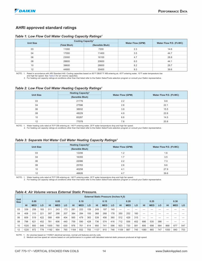
AHRI approved standard ratings
Table 1: Low Flow Coil Water Cooling Capacity Ratings1
Table 2: Low Flow Coil Water Heating Capacity Ratings1
Table 3: Separate Hot Water Coil Water Heating Capacity Ratings1
Table 4: Air Volume versus External Static Pressure.
Unit SizeCooling Capacity2
Water Flow (GPM) Water Flow P .D . (Ft-WC)(Total Btuh) (Sensible Btuh)
03 11000 7200 2.3 14.6
04 17000 11400 3.5 44.7
06 23000 16100 4.7 28.8
08 28800 20600 6.0 44.1
10 39600 26600 8.2 29.7
12 44900 30400 9.3 39.6
NOTE: 1. Rated in accordance with ARI Standard 440. Cooling capacities based on 80°F DB/67°F WB entering air, 45°F entering water, 10°F water temperature rise and high fan speed. See Table 6 for air volume capacities.2. For heating coil capacity ratings at conditions other than that listed refer to the Daikin SelectTools selection program or consult your Daikin representative.
Unit SizeHeating Capacity2
Water Flow (GPM) Water Flow P .D . (Ft-WC)(Sensible Btuh)
03 21776 2.2 9.8
04 27596 2.8 22.1
06 38932 3.9 15.5
08 48229 4.9 22.6
10 65287 6.6 14.5
12 77078 7.8 20.8
NOTE: 1. Water heating coils rated at 70°F DB entering air, 140°F entering water, 20°F water temperature drop and high fan speed.2. For heating coil capacity ratings at conditions other than that listed refer to the Daikin SelectTools selection program or consult your Daikin representative.
Unit SizeHeating Capacity2
Water Flow (GPM) Water Flow P .D . (Ft-WC)(Sensible Btuh)
03 12206 1.2 1.6
04 16355 1.7 3.5
06 22086 2.2 7.3
08 25783 2.6 9.6
10 40258 4.1 27.9
12 46626 4.7 39.6
NOTE: 1. Water heating coils rated at 70°F DB entering air, 140°F entering water, 20°F water temperature drop and high fan speed.2. For heating coil capacity ratings at conditions other than that listed refer to the Daikin SelectTools selection program or consult your Daikin representative.
UnitSize
External Static Pressure (Inches H20)
0 .00 0 .05 0 .10 0 .15 0 .20 0 .25 0 .30
HI MED LO HI MED LO HI MED LO HI MED LO HI MED LO HI MED LO HI MED LO
03 339 258 183 311 243 173 281 222 159 249 197 140 — — — — — — — — —
04 408 310 221 397 298 207 384 284 193 368 268 178 350 252 160 — — — — — —
06 609 519 422 588 499 404 565 479 383 539 456 360 512 429 315 — — — — — —
08 798 621 452 781 606 440 759 590 428 736 574 416 712 556 402 686 535 386 — — —
10 1020 800 646 1000 780 630 976 761 614 950 741 598 923 720 581 895 698 564 868 677 547
12 1220 972 778 1192 954 765 1164 932 755 1137 910 748 1109 887 745 1080 865 747 1050 840 753
NOTE: 1. Air volumes based on 115/60/1 electrical services, normal unit features and dry coils.2. Medium and low speed air volume based on unit performance in a system with tabulated external static pressure produced at high speed.

performanCe daTa
www.DaikinApplied.com 15 CAT 770-17 • VERTICAL STACKED FAN COILS
Figure 3: Type “L” Copper Riser Pressure Drop
Area outside of recommended design range.
Figure 4: Thermal Expansion of Copper Risers

CAT 770-17 • VERTICAL STACKED FAN COILS 16 www.DaikinApplied.com
physICal daTa
physICal daTa
Table 5: Motor and Physical Data.
Table 6: Approximate FHSS Shipping Weights (Lbs.)
Table 7: Approximate FHSK (Knock-down Unit) Shipping Weights (Lbs.)
Unit Size
Nominal Motor Data At High SpeedReturn Air Filter Size
Maximum Discharge Grille
Size115/60/1 277/60/1
Amps Watts Amps Watts)
03 0.65 70 0.40 70 13-¾" × 18-⅞" × 1" 16" × 12"
04 1.30 146 0.45 120 13-¾" × 18-⅞" × 1" 16" × 12"
06 1.60 195 0.70 200 13-¾" × 18-⅞" × 1" 16" × 12"
08 2.40 314 1.10 290 13-¾" × 18-⅞" × 1" 16" × 12"
10 3.60 350 1.30 350 (1) 24" × 24" × 1" 24" × 14"
12 4.80 498 2.10 500 (1) 24" × 24" × 1" 24" × 14"
Unit Size Single Unit - No Pallet Single Unit with Pallet Two Units with Pallet Four Units with Pallet1
03 155 205 380 720
04 160 210 390 740
06 175 225 420 800
08 180 230 430 820
10 256 306 585 1130
12 267 317 605 1180
NOTE: 1. Standard shipping arrangement.
Unit Size Single Unit - No Pallet Two Units with Pallet Four Units with Pallet1
03 155 380 720
04 160 390 740
06 175 420 800
08 180 430 820
NOTE: 1. Standard shipping arrangement.
physICal daTa
www.DaikinApplied.com 17 CAT 770-17 • VERTICAL STACKED FAN COILS
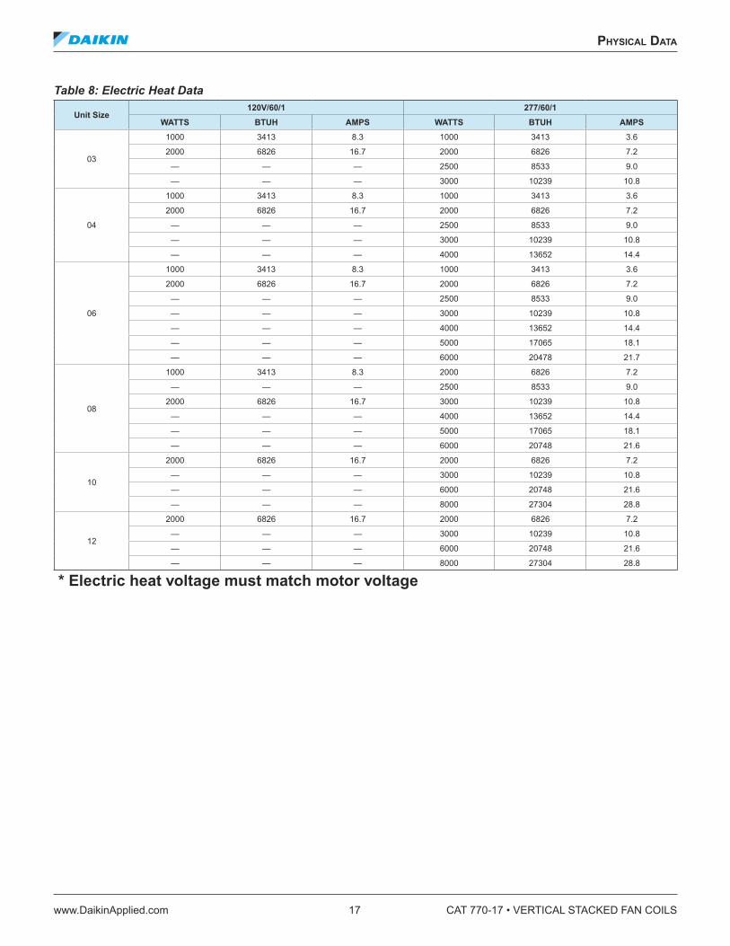
Table 8: Electric Heat Data
Unit Size120V/60/1 277/60/1
WATTS BTUH AMPS WATTS BTUH AMPS
03
1000 3413 8.3 1000 3413 3.6
2000 6826 16.7 2000 6826 7.2
— — — 2500 8533 9.0
— — — 3000 10239 10.8
04
1000 3413 8.3 1000 3413 3.6
2000 6826 16.7 2000 6826 7.2
— — — 2500 8533 9.0
— — — 3000 10239 10.8
— — — 4000 13652 14.4
06
1000 3413 8.3 1000 3413 3.6
2000 6826 16.7 2000 6826 7.2
— — — 2500 8533 9.0
— — — 3000 10239 10.8
— — — 4000 13652 14.4
— — — 5000 17065 18.1
— — — 6000 20478 21.7
08
1000 3413 8.3 2000 6826 7.2
— — — 2500 8533 9.0
2000 6826 16.7 3000 10239 10.8
— — — 4000 13652 14.4
— — — 5000 17065 18.1
— — — 6000 20748 21.6
10
2000 6826 16.7 2000 6826 7.2
— — — 3000 10239 10.8
— — — 6000 20748 21.6
— — — 8000 27304 28.8
12
2000 6826 16.7 2000 6826 7.2
— — — 3000 10239 10.8
— — — 6000 20748 21.6
— — — 8000 27304 28.8
* Electric heat voltage must match motor voltage

CAT 770-17 • VERTICAL STACKED FAN COILS 18 www.DaikinApplied.com
dImensIonal daTa
dImensIonal daTa
Model FHSS (Basic Unit) Sizes 03 Thru 08 (300 thru 800 CFM)
Recommended Riser Hole Size in Floor (inches) Riser ¾ 1 .0 1-¼ 1-½ 2 .0 2-¼ 3 .0
A 3-½ 4.0 4.0 4-½ 5.0 5-½ 6.0(Two Pipe) B 13-½ 14.0 14.0 14-½ 15.0 15-½ 16.0(Four Pipe) B 17.0 17-½ 17-½ 18.0 18-½ 19.0 19-½
All dimensions approximate. Certified drawings available upon request.
Right hand unit shown Hand of unit determined by facing return air opening.
• Risers on right = Right hand of unit. • Risers on left = Left hand of unit.• Risers on back = Neutral unit.
Mud ring can be mounted vertically or horizontally. Opening is 2" × 4"
NOTE: (1) With return air grille mounted on unit, dimension becomes 2-⅜" can be field adjusted to 3-⅜" for furred-in applications. (2) Fire Stop, if required, must be provided by the contractor.
Field riser location and discharge openings: see page 20 for detail.

dImensIonal daTa
www.DaikinApplied.com 19 CAT 770-17 • VERTICAL STACKED FAN COILS
Model FHSK (Knock-down Unit) Sizes 03 Thru 08 (300 thru 800 CFM)
Recommended Riser Hole Size in Floor (inches) Riser ¾ 1 .0 1-¼ 1-½ 2 .0 2-¼ 3 .0
A 3-½ 4.0 4.0 4-½ 5.0 5-½ 6.0(Two Pipe) B 13-½ 14.0 14.0 14-½ 15.0 15-½ 16.0(Four Pipe) B 17.0 17-½ 17-½ 18.0 18-½ 19.0 19-½
All dimensions approximate. Certified drawings available upon request.
Neutral hand unit shown Hand of unit determined by facing return air opening.
• Risers on right = Right hand of unit. • Risers on left = Left hand of unit.• Risers on back = Neutral unit.
Mud ring can be mounted vertically or horizontally. Opening is 2" × 4"
NOTE: (1) With return air grille mounted on unit, dimension becomes 2-⅜" can be field adjusted to 3-⅜" for furred-in applications. (2) Fire Stop, if required, must be provided by the contractor.
Field riser location and discharge openings: see page 20 for detail.

CAT 770-17 • VERTICAL STACKED FAN COILS 20 www.DaikinApplied.com
dImensIonal daTa
Riser Location — FHSS and FHSK Unit Sizes 03 Thru 08 (300 thru 800 CFM) 1 2 3 4 Represent air discharge positions determined by facing return air opening .
Discharge openings with one opening only, locations 1 2 3 4 should be 16" × 12" .
With two or more openings, locations 1 2 3 4 should be 16" x 6" .

dImensIonal daTa
www.DaikinApplied.com 21 CAT 770-17 • VERTICAL STACKED FAN COILS
Model FHSS (Basic Unit) Sizes 10 Thru 12 (1000 thru 1200 CFM)
Recommended Riser Hole Size in Floor (inches) Riser ¾ 1 .0 1-¼ 1-½ 2 .0 2-¼ 3 .0
A 3-½ 4.0 4.0 4-½ 5.0 5-½ 6.0(Two Pipe) B 13-½ 14.0 14.0 14-½ 15.0 15-½ 16.0(Four Pipe) B 17.0 17-½ 17-½ 18.0 18-½ 19.0 19-½
All dimensions approximate. Certified drawings available upon request.
Right hand unit shown Hand of unit determined by facing return air opening.
• Risers on right = Right hand of unit. • Risers on left = Left hand of unit.• Risers on back = Neutral unit.
Mud ring can be mounted vertically or horizontally. Opening is 2" × 4"
NOTE: (1) With return air grille mounted on unit, dimension becomes 2-⅜" can be field adjusted to 3-⅜" for furred-in applications. (2) Fire Stop, if required, must be provided by the contractor.
Field riser location and discharge openings: see page 22 for detail.

CAT 770-17 • VERTICAL STACKED FAN COILS 22 www.DaikinApplied.com
dImensIonal daTa
Riser Location — FHSS Unit Sizes 10 Thru 12 (1000 thru 1200 CFM) 1 2 3 4 Represent air discharge positions determined by facing return air opening .
DISCHARGE OPENINGS WITH ONE OPENING ONLY, LOCATIONS 1 3 SHOULD BE 24" × 14"; LOCATIONS 2 4 SHOULD BE 16" × 12" .
WITH TWO OR MORE OPENINGS, LOCATIONS 1 2 SHOULD BE 24" × 7"; LOCATIONS 3 4 SHOULD BE 16" × 6"

dImensIonal daTa
www.DaikinApplied.com 23 CAT 770-17 • VERTICAL STACKED FAN COILS
Riser Location for Master-Slave Units
= Return Air = Discharge Air
Right-HandMaster
Left-HandSlave
Right-HandSlave
Left-HandMaster
NeutralSlave
NeutralMaster
Master units ship with risers attached to the unit. These risers have 3" stub-out’s to match with our slave unit piping.
Slave units do not have ball valves attached to the valve package. Ball valves must be purchased separately for field installation (see IM 283-8).

CAT 770-17 • VERTICAL STACKED FAN COILS 24 www.DaikinApplied.com
WIrIng dIagrams
WIrIng dIagrams
Figure 5: Typical Fan Cycle Control System Wiring Diagrams – 2-Pipe
Figure 6: Typical Fan Cycle Control System Wiring Diagrams – 4-Pipe

WIrIng dIagrams
www.DaikinApplied.com 25 CAT 770-17 • VERTICAL STACKED FAN COILS
Figure 7: 2-Pipe with 1 Circuit Electric Heat Wiring Diagram
Figure 8: 4-Pipe with 1 Circuit Electric Heat Wiring Diagram

CAT 770-17 • VERTICAL STACKED FAN COILS 26 www.DaikinApplied.com
engIneerIng guIde speCIfICaTIons
engIneerIng guIde speCIfICaTIons
Model FHSS (Basic Unit) Sizes 03 thru 08 (300 thru 800 CFM) Furnish and install where shown on plans Daikin low CFM design HiLine fan coil units. Unit sizes, performance and equipment shall be as tabulated in the schedule. Unit performance shall be substantiated by software-generated output datasheets.
Unit Configuration – Unit shall be (two-pipe)(four-pipe) system blow-through configuration with completely removable chassis. Filter, fan assembly, drain line and motor shall be accessible by removing the return air grille panel. Internal controls, service valves, drain pan and coil shall be accessible by removing the access and sound baffle panel. Hand of unit shall be tabulated in the schedule.
Cabinet – Cabinet shall be fabricated of heavy-gauge galvanized steel and fully insulated with 1/2" multi-density glass fiber. An insulated galvanized steel access and sound baffle panel shall completely enclose the coil section.
Plaster Frame and Return Grille – The return air grille panel shall be heavy-gauge steel with a stamped (bar type) grille and semi-gloss finish and extend 5/8" in front of unit face. A plaster frame shall be provided to hold the return air grille panel away from the wall when the unit is furred in. A snap-on return air grille panel shall be provided with the plaster frame.
Coils – Units shall be AHRI certified with standard low flow heating/cooling coils in two-pipe systems, or, standard low flow cooling coil plus one-row heating coil in four-pipe systems. All coils shall be seamless copper tubes in a staggered pattern with rippled and corrugated aluminum fins. Tubes shall be mechanically expanded into the fin collars for positive fin-to-tube bond. Coils shall have manual air vents. Internal piping shall allow for vertical riser expansion of ±1". Coil performance shall be as tabulated in the schedule. Coil shall be positioned to provide positive condensate drainage.
Fan Assembly – Unit sizes 03 and 04: Fan housings shall be two-piece with integral scroll and inlets. Fan wheels shall be DWDI forward curved centrifugal direct drive type.
Unit sizes 06 and 08: Fan housings shall be painted steel with integral scroll and separate inlets. Fan wheels shall be painted steel DWDI forward curved centrifugal direct type.
All fan wheels shall be statically and dynamically balanced.
Motors – Motors shall be permanent split capacitor type (115/60/1) (277/60/1) with sleeve bearings, oilers, inherent thermal overload protection with automatic reset and resilient mounts.
Drain Pan – Drain pan shall be galvanized (stainless) steel with drain line and closed cell insulation on the external surface to prevent condensation.
Supply & Return Risers – Supply and return risers shall be type “L” copper (optional copper types and diameters shall be as tabulated in the schedule), with 3/4" closed cell flexible foam insulation, factory installed ball valves on risers. Slip couplings shall be factory available for field connection. Insulation shall meet or exceed current flammability classification UL94.
Drain Riser – Drain riser shall be PVC. (Optional copper types and diameters shall be as tabulated in the schedule). Stop type couplings shall be factory available for field connection.
Control Systems – A unit- or wall-mounted thermostat, shall be offered to control fan and/or valve cycling. For unit mounted thermostats all wiring shall be provided to the control box for easy field installation (optional Molex connections shall be available upon request). A 10K thermistor shall be mounted in all units. The 10K thermistor shall be used for factory provided thermostats or for field provided controls. The thermostat electrical box shall be adjustable for any wall thickness up to 3-7/8" and a 1/2" mud ring shall be provided (an optional 5/8" mud ring shall be provided upon request).
Filters – Filters shall be nominal 1" thick throwaway.
Discharge Grilles (Optional) – Optional aluminum (single deflection) (double deflection) discharge grilles shall be provided in sizes and positions as tabulated in the schedule.
Line-of-Sight Baffle (Optional) – An optional line-of-sight baffle shall be supplied as tabulated in the schedule.
Fresh Air Dampers (Optional) – Two-position (motorized)(manual) fresh air damper shall be factory available as tabulated in the schedule.
Electric Heat (Optional) – Electric heating elements and controls shall be completely installed, wired and enclosed at the factory. Heating element shall be fully protected by a high limit cut-out with automatic reset.
Controls & Valves (Optional) – Valve cycle control for two-pipe (four-pipe) systems, two-way (three-way) motorized valves and other combinations of ball valves* and automatic flow metering devices shall be installed as tabulated in the schedule.
Twin Units (Optional) – Twin unit configuration, as tabulated, shall be such that two adjacent room units will be piped to a single set of risers and will operate with separate controls on each unit.
* Ball shut-off valves are not included with factory valve packages. They are only provided with factory risers.

engIneerIng guIde speCIfICaTIons
www.DaikinApplied.com 27 CAT 770-17 • VERTICAL STACKED FAN COILS
Unit Sizes 10 & 12 (1000 thru 1200 CFM) Furnish and install where shown on plans Daikin low CFM design HiLine fan coil units. Unit sizes, performance and equipment shall be as tabulated in the schedule. Unit performance shall be substantiated by software-generated output datasheets.
Unit Configuration – Unit shall be (two-pipe)(four-pipe) system blow-through configuration with completely removable chassis. Filter, fan assembly, drain line and motor shall be accessible by removing the return air grille panel. Internal controls, service valves, drain pan and coil shall be accessible by removing the access and sound baffle panel. Hand of unit shall be tabulated in the schedule.
Cabinet – Cabinet shall be fabricated of heavy-gauge galvanized steel and fully insulated with 1/2" multi-density glass fiber. An insulated galvanized steel access and sound baffle panel shall completely enclose the coil section.
Plaster Frame and Return Grille – The return air grille panel shall be heavy-gauge steel with a stamped (bar type) grille and semi-gloss finish and extend 5/8" in front of unit face. A plaster frame shall be provided to hold the return air grille panel away from the wall when the unit is furred in. A snap-on return air grille panel shall be provided with the plaster frame.
Coils – Units shall be AHRI certified with standard low flow heating/cooling coils in two-pipe systems, or, standard low flow cooling coil plus one-row heating coil in four-pipe systems. All coils shall be seamless copper tubes in a staggered pattern with rippled and corrugated aluminum fins. Tubes shall be mechanically expanded into the fin collars for positive fin-to-tube bond. Coils shall have manual air vents. Internal piping shall allow for vertical riser expansion of ±1". Coil performance shall be as tabulated in the schedule. Coil shall be positioned to provide positive condensate drainage.
Fan Assembly – Unit sizes 03 and 04: Fan housings shall be two-piece with integral scroll and inlets. Fan wheels shall be DWDI forward curved centrifugal direct drive type.
Unit sizes 06 and 08: Fan housings shall be painted steel with integral scroll and separate inlets. Fan wheels shall be painted steel DWDI forward curved centrifugal direct type.
All fan wheels shall be statically and dynamically balanced.
Motors – Motors shall be permanent split capacitor type (115/60/1) (277/60/1) with sleeve bearings, oilers, inherent thermal overload protection with automatic reset and resilient mounts.
Drain Pan – Drain pan shall be galvanized (stainless) steel with drain line and closed cell insulation on the external surface to prevent condensation.
Supply & Return Risers – Supply and return risers shall be type “L” copper (optional copper types and diameters shall be as tabulated in the schedule), with 3/4" closed cell flexible foam insulation, factory installed ball valves on risers. Slip couplings shall be factory available for field connection. Insulation shall meet or exceed current flammability classification UL94.
Drain Riser – Drain riser shall be PVC. (Optional copper types and diameters shall be as tabulated in the schedule). Stop type couplings shall be factory available for field connection.
Control Systems – A unit- or wall-mounted thermostat, shall be offered to control fan and/or valve cycling. For unit mounted thermostats all wiring shall be provided to the control box for easy field installation (optional Molex connections shall be available upon request). A 10K thermistor shall be mounted in all units. The 10K thermistor shall be used for factory provided thermostats or for field provided controls. The thermostat electrical box shall be adjustable for any wall thickness up to 3-7/8" and a 1/2" mud ring shall be provided (an optional 5/8" mud ring shall be provided upon request).
Filters – Filters shall be nominal 1" thick throwaway.
Discharge Grilles (Optional) – Optional aluminum (single deflection) (double deflection) discharge grilles shall be provided in sizes and positions as tabulated in the schedule.
Line-of-Sight Baffle (Optional) – An optional line-of-sight baffle shall be supplied as tabulated in the schedule.
Fresh Air Dampers (Optional) – Two-position (motorized)(manual) fresh air damper shall be factory available as tabulated in the schedule.
Electric Heat (Optional) – Electric heating elements and controls shall be completely installed, wired and enclosed at the factory. Heating element shall be fully protected by a high limit cut-out with automatic reset.
Controls & Valves (Optional) – Valve cycle control for two-pipe (four-pipe) systems, two-way (three-way) motorized valves and other combinations of ball valves* and automatic flow metering devices shall be installed as tabulated in the schedule.
Twin Units (Optional) – Twin unit configuration, as tabulated, shall be such that two adjacent room units will be piped to a single set of risers and will operate with separate controls on each unit.
* Ball shut-off valves are not included with factory valve packages. They are only provided with factory risers.

CAT 770-17 • VERTICAL STACKED FAN COILS 28 www.DaikinApplied.com
engIneerIng guIde speCIfICaTIons
Model FHSK (Knock-down Unit) Sizes 03 Thru 08 (300 Thru 800 CFM) Furnish and install where shown on plans Daikin low CFM design HiLine fan coil units. Unit sizes, performance and equipment shall be as tabulated in the schedule. Unit performance shall be substantiated by software-generated output datasheets.
Unit Configuration – Unit shall be (two-pipe)(four-pipe) system blow-through configuration with completely removable chassis. Filter, fan assembly, drain line and motor shall be accessible by removing the return air grille panel. Internal controls, service valves, drain pan and coil shall be accessible by removing the access and sound baffle panel. Hand of unit shall be tabulated in the schedule.
Cabinet – Cabinet shall be fabricated of heavy-gauge galvanized steel and fully insulated with 1/2" multi-density glass fiber. An insulated galvanized steel access and sound baffle panel shall completely enclose the coil section.
Plaster Frame and Return Grille – The return air grille panel shall be heavy-gauge steel with a stamped (bar type) grille and semi-gloss finish and extend 5/8" in front of unit face. A plaster frame shall be provided to hold the return air grille panel away from the wall when the unit is furred in. A snap-on return air grille panel shall be provided with the plaster frame.
Coils – Units shall be AHRI certified with standard low flow heating/cooling coils in two-pipe systems, or, standard low flow cooling coil plus one-row heating coil in four-pipe systems. All coils shall be seamless copper tubes in a staggered pattern with rippled and corrugated aluminum fins. Tubes shall be mechanically expanded into the fin collars for positive fin-to-tube bond. Coils shall have manual air vents. Internal piping shall allow for vertical riser expansion of ±1". Coil performance shall be as tabulated in the schedule. Coil shall be positioned to provide positive condensate drainage.
Fan Assembly – Unit sizes 03 and 04: Fan housings shall be two-piece with integral scroll and inlets. Fan wheels shall be DWDI forward curved centrifugal direct drive type.
Unit sizes 06 and 08: Fan housings shall be painted steel with integral scroll and separate inlets. Fan wheels shall be painted steel DWDI forward curved centrifugal direct type.
All fan wheels shall be statically and dynamically balanced.
Motors – Motors shall be permanent split capacitor type (115/60/1) (277/60/1) with sleeve bearings, oilers, inherent thermal overload protection with automatic reset and resilient mounts.
Drain Pan – Drain pan shall be galvanized (stainless) steel with drain line and closed cell insulation on the external surface to prevent condensation.
Supply & Return Risers – Supply and return risers shall be type “L” copper (optional copper types and diameters shall be as tabulated in the schedule), with 3/4" closed cell flexible foam insulation, factory installed ball valves on risers. Slip couplings shall be factory available for field connection. Insulation shall meet or exceed current flammability classification UL94.
Drain Riser – Drain riser shall be PVC. (Optional copper types and diameters shall be as tabulated in the schedule). Stop type couplings shall be factory available for field connection.
Control Systems – A unit- or wall-mounted thermostat, shall be offered to control fan and/or valve cycling. For unit mounted thermostats all wiring shall be provided to the control box for easy field installation (optional Molex connections shall be available upon request). A 10K thermistor shall be mounted in all units. The 10K thermistor shall be used for factory provided thermostats or for field provided controls. The thermostat electrical box shall be adjustable for any wall thickness up to 3-7/8" and a 1/2" mud ring shall be provided (an optional 5/8" mud ring shall be provided upon request).
Filters – Filters shall be nominal 1" thick throwaway.
Discharge Grilles (Optional) – Optional aluminum (single deflection) (double deflection) discharge grilles shall be provided in sizes and positions as tabulated in the schedule.
Line-of-Sight Baffle (Optional) – An optional line-of-sight baffle shall be supplied as tabulated in the schedule.
Fresh Air Dampers (Optional) – Two-position (motorized)(manual) fresh air damper shall be factory available as tabulated in the schedule.
Electric Heat (Optional) – Electric heating elements and controls shall be completely installed, wired and enclosed at the factory. Heating element shall be fully protected by a high limit cut-out with automatic reset.
Controls & Valves (Optional) – Valve cycle control for two-pipe (four-pipe) systems, two-way (three-way) motorized valves and other combinations of ball valves* and automatic flow metering devices shall be installed as tabulated in the schedule.
Twin Units (Optional) – Twin unit configuration, as tabulated, shall be such that two adjacent room units will be piped to a single set of risers and will operate with separate controls on each unit.
* Ball shut-off valves are not included with factory valve packages. They are only provided with factory risers.


Daikin Applied Training and DevelopmentNow that you have made an investment in modern, efficient Daikin equipment, its care should be a high priority. For training information on all Daikin HVAC products, please visit us at www.DaikinApplied.com and click on Training, or call 540-248-9646 and ask for the Training Department.
Warranty
All Daikin equipment is sold pursuant to its standard terms and conditions of sale, including Limited Product Warranty. Consult your local Daikin Applied representative for warranty details. To find your local Daikin Applied representative, go to www.DaikinApplied.com.
Aftermarket Services
To find your local parts office, visit www.DaikinApplied.com or call 800-37PARTS (800-377-2787). To find your local service office, visit www.DaikinApplied.com or call 800-432-1342.
This document contains the most current product information as of this printing. For the most up-to-date product information, please go to www.DaikinApplied.com.
Products manufactured in an ISO Certified Facility.
CAT 770-17 (12/14) ©2014 Daikin Applied | (800) 432–1342 | www.DaikinApplied.com