high voltage design - eit
TRANSCRIPT

3/26/2014
1
www.eit.edu.au
Munch, Lunch and Learn:
High Voltage
Design
www.eit.edu.au
Steve Mackay• Dean of Engineering• Worked for 30 years in Industrial Automation• 30 years experience in mining, oil and gas,
electrical and manufacturing industries
Engineering Institute of Technology (EIT)
High Voltage Design Webinar

3/26/2014
2
www.eit.edu.au
Munch, Lunch and Learn: High Munch, Lunch and Learn: High Munch, Lunch and Learn: High Munch, Lunch and Learn: High Voltage DesignVoltage DesignVoltage DesignVoltage Design
• During the session, a brief review of the key concepts of High Voltage Design referring to the applicable standards
• Update your knowledge on HV design and installations issues
• Review the essentials of AS 2067-2008 standard
www.eit.edu.au
AS2067 AS2067 AS2067 AS2067 –––– 2008200820082008Substations & HV
Installations exceeding 1kVac
Engineering Institute of Technology (EIT)
High Voltage Design Webinar

3/26/2014
3
www.eit.edu.au
AS 2067- ScopeHigh voltage installationHigh voltage installationHigh voltage installationHigh voltage installation• Electricity network substationlectricity network substationlectricity network substationlectricity network substation, under control of electricity
network operator or entity authorized by license/other legal instrument to convey electricity
• High voltage parts of electrical installation of power station power station power station power station including all auxiliary systems, interconnecting lines, cables between power stations, if on same site
• High voltage parts of electrical installation not covered in electrical installation not covered in electrical installation not covered in electrical installation not covered in (a) and (b) above.(a) and (b) above.(a) and (b) above.(a) and (b) above. May include but not limited to consumer consumer consumer consumer and customer electrical and customer electrical and customer electrical and customer electrical installations serving premises such as factories, commercial facilities, industrial plants, institutional facilities and mine sites”
www.eit.edu.au
• AS 2067 refers to mine site electrical installations by exception; Standard applies to mine site electrical installations, parts of such installations for which mining specific legislation does not set other or additional requirements
• AS 2067 contains mandatory requirements for Western Australian mine sites as per “Mines Safety and Inspection Regulations” 1995 r. 5.3
Scope & definitions
Engineering Institute of Technology (EIT)
High Voltage Design Webinar
3/26/2014
4
www.eit.edu.au
• AS 2067 does not apply to design, erection of any of following:– Overhead lines, underground cables between separate
installations (Dealt with in AS/NZS 7000) – Ship and offshore installations– Mine site electrical installations, parts of such
installations (Fixed infrastructure compliant with AS/NZS 3000 covered by AS 2067)
– Switchgear and/or transformers and/or electrical equipment located within closed electrical operating area supplied at LV and where contact cannot be made with HV conductors. (e.g. X-ray equipment)
– Test sites
AS 2067- Exclusions
www.eit.edu.au
• AS 2067:2008 “Substations and high voltage installations exceeding 1kV A.C.” (replacing AS 2067:1984 “Switchgear assemblies and ancillary equipment for alternating voltages above 1kV”)
• Amendment 1 of AS 2067:2008 published in 2010 • Project approved by Standards Australia to review AS2067
– commenced in 2012– Sub-committees have been established to consider:
� Earthing of installations� Arc flash hazards of electrical installations
AS 2067- Status
Engineering Institute of Technology (EIT)
High Voltage Design Webinar
3/26/2014
5
www.eit.edu.au
• SECTION 1 SCOPE AND DEFINITIONS• SECTION 2 FUNDAMENTAL REQUIREMENTS• SECTION 3 INSULATION COORDINATION• SECTION 4 EQUIPMENT• SECTION 5 INSTALLATIONS• SECTION 6 SAFETY MEASURES• SECTION 7 PROTECTION, CONTROL AND AUXILIARY SYSTEMS• SECTION 8 EARTHING SYSTEMS• SECTION 9 INSPECTION AND TESTING• SECTION 10 OPERATION AND MAINTENANCE MANUAL• SECTION 11 ADDITIONAL REQUIREMENTS FOR CONSUMER HV• APPENDIX AAPPENDIX AAPPENDIX AAPPENDIX A VOLTAGE LIMITS• APPENDIX BAPPENDIX BAPPENDIX BAPPENDIX B DISTRIBUTION SUBSTATIONS EARTHING SYSTEM• APPENDIX CAPPENDIX CAPPENDIX CAPPENDIX C FIRE RISK ZONES FOR DISTRIBUTION SUBSTATIONS• APPENDIX DAPPENDIX DAPPENDIX DAPPENDIX D EMF AND SAFETY ISSUES
AS 2067- Contents
www.eit.edu.au
• Installations, equipment must be capable of withstanding electrical, mechanical stresses, together with climatic, environmental impactsanticipated on site• Installations, equipment must identify safety requirements to be met for levels of segregation• Installations must be designed, constructed, erected to safely withstand mechanical, thermal effects resulting from short-circuit currents• Sets mandatory structural requirements• Sets mandatory climatic and environmental requirements
Fundamental requirements
Engineering Institute of Technology (EIT)
High Voltage Design Webinar
3/26/2014
6
www.eit.edu.au
• Covers specific primary equipment selection requirements
• Includes circuit breakers, disconnectors, power transformers, reactors, gas insulated switchgear (GIS), CTs, VTs, surge arresters, and capacitor banks
• AS 2374 power transformers, AS 62271 HV switchgear and control gear contain additional detailed requirements
• Additional specific requirements for cables• Overhead lines shall comply with C(b)1
Equipment
www.eit.edu.au
• General requirements for circuit arrangement, circuit documentation, lighting, operational safety and labelling
• Specific requirements for open type indoor, outdoor installations
• Specific requirements for indoor switchboard installations
• Specific requirements for buildings including prefabricated substations, installations on mast, pole or tower
• Contains drawings of operational application of safety clearances
Installation
Engineering Institute of Technology (EIT)
High Voltage Design Webinar

3/26/2014
7
www.eit.edu.au
• Contains requirements for protection against direct contact with live parts and work practices requirements for protection of personnel
• Important detailed requirements for protection from arc fault, lightning, fire and explosion
Safety measures
www.eit.edu.au
• Design, installation, testing and maintenance of earthing system should be such, that it operates under all conditions and ensures acceptable safety compliance in any place to which persons have legitimate access
• Provides criteria to ensure that integrity of equipment connected and in proximity to earthing system is maintained
Earthing systems
Engineering Institute of Technology (EIT)
High Voltage Design Webinar

3/26/2014
8
www.eit.edu.au
• Shock hazard to human beings - Current that is sufficient to cause ventricular fibrillation flowing through region of the heart
• Current limit, for power-frequency purposes, shall be derived from AS/NZS 60479.1
• For HV installation design, this current limit should be translated into voltage limits for comparison with calculated step and touch voltages, taking into account impedance present in body current path
Earthing - Safety criteria
www.eit.edu.au
• Shall take into account following factors:– Proportion of current flowing through region of heart
(based on Heart Current Factor, Table 5 in AS/NZS 60479.1:2002);
– Permissible ventricular fibrillation (based on Figure 14 in AS/NZS 60479.1:2002)
– Body impedance along current path (based on values of Table 5.1 of AS/NZS 60479.1:2002)
– Resistance between body contact points (e.g. metal structure to hand including glove, feet to ground including shoes/gravel)
– Fault duration – Probability of fault occurrence, presence of human beings
in location where they will be exposed to voltage
Earthing - Safety voltage limits
Engineering Institute of Technology (EIT)
High Voltage Design Webinar

3/26/2014
9
www.eit.edu.au
• Insulation coordination shall be in accordance with AS 1824 “Insulation Coordination”
• However, Basic Impulse Level (BIL) coordination is difficult to inspect
• Insulation strength must be coordinated to withstand lightning and switching impulse levellightning and switching impulse levellightning and switching impulse levellightning and switching impulse level
• Must have a coordinated BIL - Power transformers, earthing compensators, circuit breakers, CTs, VTs, cables, cable joints, cable sealing ends
Insulation coordination
www.eit.edu.au
Insulation coordination
• Process of determining proper insulation levels of various components in power system and their arrangements
• Selection of insulation structure that will withstand voltage stresses to which system/equipment will be imposed to, together with proper surge arrester
• Process is determined from known characteristics of voltage surges and characteristics of surge arresters
Engineering Institute of Technology (EIT)
High Voltage Design Webinar
3/26/2014
10
www.eit.edu.au
Basic insulation level (BIL)
• Insulation strength of equipment (transformers, circuit breakers, etc.) should be higher than that of lightning arresters, other surge protective devices
• To protect equipment from overvoltages, necessary to fix insulation level for system so that no insulation should break down or flash over below this level
• Reference insulation level expressed as impulse crest (or peak) voltage with standard wave not longer than 1.2 x 50 ɥsec wave
• Impulse takes 1.2 µsec to reach peak and then decays to 50% of peak in 50 µsec
www.eit.edu.au
• Sustained low frequency tests conducted at 50 Hz• Performed on:– Insulation materials to determine dielectric strength, dielectric loss– Routine testing of supply mains– Work tests on HV transformers, porcelain insulators and such apparatus• Tests carried out at highest possible voltage (e.g.
2000 kV for insulators, HV cables)
• A.C. HV tests as routine tests on LV equipment:– 1kV + (2 x Working voltage)– 1.5 ~ 2 kV for a 230 V equipment
Power frequency test
Engineering Institute of Technology (EIT)
High Voltage Design Webinar

3/26/2014
11
www.eit.edu.au
Power frequency test
• HV test voltage generated using transformer - need not be of high power rating
• Transformers designed with poor regulation –Reduced voltage during insulation breakdown
• Series resistance to limit breakdown current
www.eit.edu.au
2. Power system planning2. Power system planning2. Power system planning2. Power system planning
High Voltage Design andHigh Voltage Design andHigh Voltage Design andHigh Voltage Design andInstallations Master ClassInstallations Master ClassInstallations Master ClassInstallations Master Class
Engineering Institute of Technology (EIT)
High Voltage Design Webinar

3/26/2014
12
www.eit.edu.au
Learning objectives• Planning criteria• Load forecasting• Voltage selection• Site conditions• Security of supply• System studies
– Load flow analysis– Fault calculations
www.eit.edu.au
• Client often unsure of electrical features/ implications, may need assistance. May not have experienced electrical team.• Design engineer not always aware of client’s specific needs• Different parties involved in design must follow same rules• Outcome - Often confusion, reworking, arguments, delays and budget blowouts• Client may get a system that doesn’t always meet expectations
Importance of planning
Engineering Institute of Technology (EIT)
High Voltage Design Webinar

3/26/2014
13
www.eit.edu.au
• Need to agree on basic system requirements, power supply conditions
• Client needs to liaise with Supply Authority or packaged power station vendor
• Details that do not affect cost/ program can be discussed later
• Sooner all features are agreed, lesser the confusion, time wastage
Meeting with customer
www.eit.edu.au
• Systems:– Safety– Reliability– Flexibility
• Load forecasting (average, peak, base load, etc.)• Voltage selection• Power quality (harmonics, voltage flicker, BIL, etc.)
Planning criteria
Cont….
Engineering Institute of Technology (EIT)
High Voltage Design Webinar

3/26/2014
14
www.eit.edu.au
• Site conditions (IP rating, soil resistivity, etc.)
• Security of supply (duration of outages, frequency, Busbar configurations)
• System studies– Load flow analysis– Fault calculations
Planning criteria
www.eit.edu.au
System safety
• Enough clearance distances between live parts, between live parts and ground
• Efficient grounding system - Transformer neutral grounding, soil resistivity, numbers of earthing rods, size of earthing cables
• Appropriate recloser shots, timings. Not enabling reclosers in close vicinity of residential areas
• Fast clearance of faults
• Adequate insulation discs on O/H line insulators
Cont….
Engineering Institute of Technology (EIT)
High Voltage Design Webinar

3/26/2014
15
www.eit.edu.au
System safety
• Appropriate size cables, lines - Ampacity, short circuit capacity
• Enabling switch-onto-fault (SOTF) feature on numerical relays
• Application of surge arresters at power transformer bushings
• Adopting simple systems instead of complicated systems (e.g. single bus instead of main and transfer bus)
www.eit.edu.au
System flexibility• Can add/change loads without difficulty - Proper
busbar configurations, connections
• Spare feeders even if breakers are not furnished
• Spare space in substations - Future transformer bays, incoming feeders for any significant load rise in future
• Enough ampacity, short circuit capability for line conductors, cables with regard to prospective future load increases
• Enough capacity for transformers to prevent overloading during future expansion projects
Engineering Institute of Technology (EIT)
High Voltage Design Webinar
3/26/2014
16
www.eit.edu.au
• Has Contractual Maximum Demand (CMD) been discussed with Supply Authority?
Load survey should determine following issues:
• Peak load, maximum demand, diversity factor, load factor and demand factor to define size of equipment needed
• Critical load, essential loads, general purpose/non-critical loads
• Constant voltage supply, no sags or surges
• Harmonic currents, filtering, etc.
Load forecasting
www.eit.edu.au
Peak load: Maximum load - Instantaneous maximum or maximum average over time period
Average load: Load averaged over period of time -One day, one week, one month or a year
Connected load: Sum of electrical ratings of all loads connected
Demand: Electric load averaged over time period usually in kW or kVA. Averaging time - 15 min or 30 min or one hour
Load forecasting
Cont……
Engineering Institute of Technology (EIT)
High Voltage Design Webinar
3/26/2014
17
www.eit.edu.au
Maximum demand: Greatest of all demands that have occurred during specific period
• For billing purposes – Usually one month
• For design purposes it is design life of plant or planning period
Load factor = (average load) / (peak load)
Demand factor = (Maximum demand) / (connected load)
Diversity factor = (sum of individual maximum demands) / (total demand)
Load forecasting
www.eit.edu.au
Demand factor
• Customers often characterized by total connected kVA - However, it is unlikely that all equipment are simultaneously on
• E.g. Customer may have connected load of 400 kVA, while max. demand of 150 kVA may by read from customer’s meter at particular point of time
• Demand factor: Ratio of peak kVA to total connected kVA (150/400 = 0.375 in above case)
• Demand factor =
Engineering Institute of Technology (EIT)
High Voltage Design Webinar
3/26/2014
18
www.eit.edu.au
Diversity factor• Most loads are turned on/off randomly
− Probability of all customers experiencing same peak demand simultaneously is small
− Probability decreases as number of customers increases
• Distribution systems can be designed to supply less power than sum of individual customer peak demands
• Diversity factor: Ratio of sum of individual customer peak demands to peak system demand
• Diversity factor =
www.eit.edu.au
Demand factor and Diversity factor -
Calculations
There are four individual feeders having connected loads of 250 kVA, 300 kVA, 350 kVA and 100 kVA. The demand factors for these are 80%, 70%, 75% and 90% respectively. The diversity factor is 1.6.
Calculate the:1) Total demand of the loads and2) Size of the transformer required to supply these
loads.
Engineering Institute of Technology (EIT)
High Voltage Design Webinar

3/26/2014
19
www.eit.edu.au
Demand factor and Diversity factor -Calculations
Solution:
Calculating demand for feeder loads
250 kVA x 80% = 200 kVA
300 kVA x 70% = 210 kVA
350 kVA x 75% = 262.5 kVA
100 kVA x 90% = 90 kVA
Total demand of the loads = 762.50 kVACont….
www.eit.edu.au
Demand factor and Diversity factor -
Calculations
Total demand of the loads = 762.50 kVA
Diversity factor provided is 1.6
The actual demand of all the loads = 762.5 /
1.6
= 476.6
kVA
Therefore size of transformer required = 500
kVA
Engineering Institute of Technology (EIT)
High Voltage Design Webinar

3/26/2014
20
www.eit.edu.au
• Supply authority must provide fault levels at Point of Supply• Supply authorities nominate power factor limits at Point of Supply (sometimes a specific contract agreement)• Power authorities concerned about harmonic distortion at Point of Supply• Supply earthing affects plant earthing, Basic Insulation Levels (BIL)• Need protection details at Point of Supply for grading with downstream protection devices
Power quality
www.eit.edu.au
• Defining site voltage levels, limits a common problem
• One criterion could be to restrict voltage levels to max. voltage drop of x%. Can be confusing, as it often does not consider upstream voltage values
• Better to nominate absolute values of voltage at a node, avoiding concerns about which elements of supply system are involved
Voltage limits
Engineering Institute of Technology (EIT)
High Voltage Design Webinar

3/26/2014
21
www.eit.edu.au
Voltage level selection
• Important for economic, operational aspects of system
• Higher the voltage, lower the current needed for any load
• Conductor size and voltage drop in feeders directly result of current to be carried
• Too small conductors will not have physical strength to handle all conditions
• Higher voltages can be more expensive because of increased insulation
www.eit.edu.au
Voltage (V)Voltage (V)Voltage (V)Voltage (V) Current (A)Current (A)Current (A)Current (A) Load (KVA)Load (KVA)Load (KVA)Load (KVA) 80% KVA (Load)80% KVA (Load)80% KVA (Load)80% KVA (Load)480480480480 20040060080012001600200030004000 16633350066710001330166325003325 13326640053280010651330200026602400240024002400 40080012002000 1663333350008313 13302660400066504160416041604160 600120020003000 432586501441021600 34606920115301728012470124701247012470 600120020003000 13720259204320064700 1097520735345605183513200132001320013200 600120020003000 13270274354572568590 1097521950365805487013800138001380013800 600120020003000 14340286804780071700 11475229503834557365
Voltage level selection
Engineering Institute of Technology (EIT)
High Voltage Design Webinar
3/26/2014
22
www.eit.edu.au
• Design ambient temperatures, air conditioning temperature limits plus AC security
• Ground temperatures, soil thermal resistivity• Wind conditions including those for overhead line
summer ratings• Dust, rain, condensation, corrosion, leading to IP
ratings• Ground conditions including termite prevalence or
incompact soil
Site conditions
www.eit.edu.au
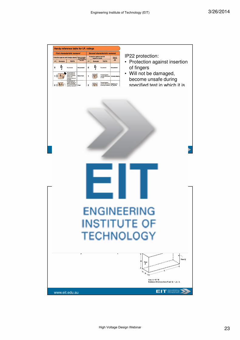
• Classifies, rates degree of protection provided against intrusion of:
− Solid objects (including body parts like hands, fingers)
− Dust− Accidental contact− Water
in mechanical casings and with electrical enclosures
IP Code, Ingress Protection Rating
Engineering Institute of Technology (EIT)
High Voltage Design Webinar
3/26/2014
23
www.eit.edu.au
IP22 protection:• Protection against insertion
of fingers• Will not be damaged,
become unsafe during specified test in which it is exposed to vertically or nearly vertically dripping water
• Typical minimum requirement for design of electrical accessories for indoor use
www.eit.edu.au
• Measure of resistance to current flow in ground
• Earthing effectiveness is a function of low soil resistivity
• Resistivity of soil can vary depending on:− Moisture content− Conducting salts concentration− Compaction level− Temperature
Soil resistivity in Ohm meters р = R * A / L
Soil electrical resistivity
Engineering Institute of Technology (EIT)
High Voltage Design Webinar

3/26/2014
24
www.eit.edu.au
System reliability
• Distribution reliability primarily relates to equipment outages and customer interruptions
• Normal operating conditions - All equipment (except standby equipment) energized and all customers receive power
• Scheduled outages (e.g. maintenance) and unscheduled events disrupt normal operating conditions and can lead to outages, interruptions
Cont…..
www.eit.edu.au
System reliability
• System Average Interruption Frequency Index
SAIFI = (Total number of customer interruptions) / (Total number of customers served)
• System Average Interruption Duration Index
SAIDI = (Total customer interruption durations) / (Total number of customers served)
• Customer Average Interruption Duration Index
CAIDI = (Total customer interruption durations) / (Total number of customer interruptions)
Engineering Institute of Technology (EIT)
High Voltage Design Webinar

3/26/2014
25
www.eit.edu.au
On 28th of a month five outages were recorded. The table below shows each outage, the duration of the outage, and the number of customers affected by outage. The utility has a total of 50,000 customers. Calculate the following.
a) SAIDIb) CAIDIc) SAIFId) CAIFIe) MAIFI
Assume the system had six momentary substation breaker operations on 28th. One breaker operated twice affecting 1015 customers and four other breakers operated once affecting 867, 2005, 1500, and 1330 customers.
Date TimeNo. of
customersDuration
28th 9:53 10 90
28th 11:02 1000 20
28th 13:15 2 175
28th 20:48 1 120
28th 22:35 1 38
System reliability - Calculations
www.eit.edu.au
The first outage was at 9:53 in the morning and 10 customers where out of service for 90 minutes (1.5 hours). Therefore, the customer hours are 10 * 1.5 or 15 hours.
Date Time No. of customers Duration Customer-hours
28th 9:53 10 90 15.00
28th 11:02 1000 20 333.33
28th 13:15 2 175 5.83
28th 20:48 1 120 2.00
28th 22:35 1 38 0.63
Total 1,014 443 356.80
The customer hours are calculated for each outage and then summed for a total of 356.80 customer-hours. i.e. The result is 356.80 * 60 = 21408 customer-minutes.
System reliability - Calculations
Engineering Institute of Technology (EIT)
High Voltage Design Webinar

3/26/2014
26
www.eit.edu.au
= 21408/50000= 0.428 minutes
This says that the average customer was out for 0.428 minutes on the 28th of the month.
= 21408/1014= 21.1 minutes
On average, any customer who experienced an outage on the 28th was out of service for 21.1 minutes.
served customers ofnumber Total
durationson interrupticustomer all of SumSAIDI=
SAIFI
SAIDI
onsinterrupticustomer ofnumber Total
durationson interrupticustomer all of SumCAIDI ==
System reliability - Calculations
www.eit.edu.au
System reliability - Calculations
= 1014/50000= 0.020
This says that on the 28th of the month, the customers at this utility had a 0.020 probability of experiencing a power outage.
= 5/1014= 0.005
This says that the average number of interruptions for a customer who was interrupted is 0.005 times.
oninterrupti oneatleast had whocustomers ofnumber Total
onsinterrupticustomer ofnumber TotalCAIFI=
served customers ofnumber Total
onsinterrupticustomer ofnumber TotalSAIFI=
Engineering Institute of Technology (EIT)
High Voltage Design Webinar

3/26/2014
27
www.eit.edu.au
System reliability - Calculations
MAIFI = ∑ (IDi * Ni) / NT
∑(IDi * Ni) = (2 * 1015) + (1 * 867) + (1 * 2005) + (1 * 1500) + (1 * 1330)= 7732 customer-interruptions
MAIFI = 7732/50000= 0.154
On average, the customers experienced 0.128 momentary interruptions on the 28th.
served customers ofnumber Total
timedefined than theless onsinterrupticustomer ofnumber TotalMAIFI=
www.eit.edu.au
• Categorize site loads into emergency, essential, non-essential loads; Agree on outage criteria and backup arrangement for each• Permissible out-of-service time - Important parameter in determining backup arrangement for category of supply• Identify items of plant that can be shed for isolated system• Failure cause-and-effect analysis will influence switching facilities
Security of supply (S.O.S)
Engineering Institute of Technology (EIT)
High Voltage Design Webinar

3/26/2014
28
www.eit.edu.au
System reliability
Selecting voltages:
• Distribution systems used for residential, commercial loads exposed to many hazards. Transmission systems are more reliable
• Technical considerations prevail economic considerations for transmission systems (High quality equipment together with fast, reliable protection systems used for transmission)
Redundancy:
• Duplication of power paths between source and load provide additional reliability
• Allows maintenance of one path while the other is being used
Cont…..
www.eit.edu.au
System reliability
• Protection coordination: Selective, coordinated protection system removes minimum number of loads for any fault without affecting other loads
• Simple power systems: Simple systems normally provide more reliability due to their simple interlocking logic, simple protection logic, simple intertripping scheme
• Monitoring and control: Proper alarms, switching, intertripping, and interlocking will result in minimum outage
Engineering Institute of Technology (EIT)
High Voltage Design Webinar
3/26/2014
29
www.eit.edu.au
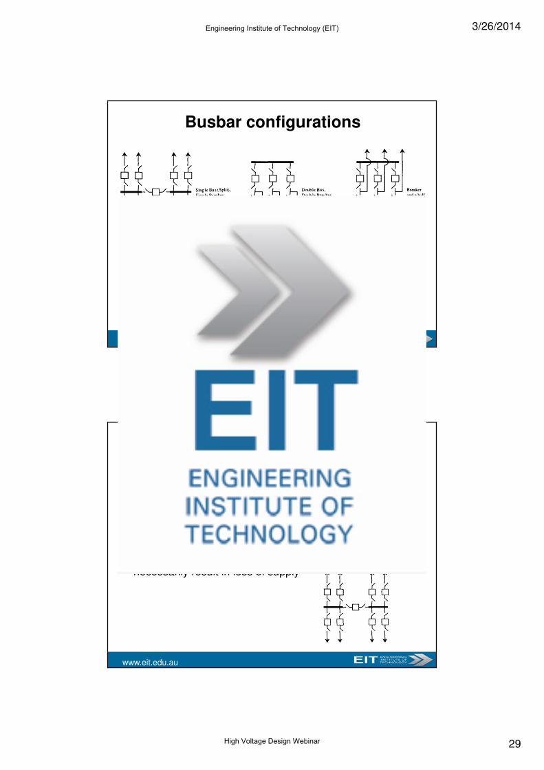
Busbar configurations
www.eit.edu.au
Single busbar with single breaker
• Simple to operate, low cost• Used generally in small outdoor substations with relatively
few outgoing/incoming feeders/lines. Not normally used in major substations
• Economical addition of future feeder bays• Feeder breaker maintenance involves loss of that circuit• Minimum reliance on signaling for satisfactory protection• Each circuit with its own breaker – Plant outage does not
necessarily result in loss of supply
Engineering Institute of Technology (EIT)
High Voltage Design Webinar

3/26/2014
30
www.eit.edu.au
Double busbar with single breaker
• Utilizes single breaker per circuit that can be connected to either bus
• Tie breaker between buses allows circuits to be transferred without being de-energised
• Requires four switches per circuit – Issues like space, maintenance, reliability important
• Double bus with single breaker configuration well suited for GIS applications
www.eit.edu.au
Double busbar with double breakers
• Configuration used for large switching stations• Requires two breakers for each feeder circuit, makes it
expensive• Each circuit, normally connected to both buses – Makes this
configuration reliable and flexible
Engineering Institute of Technology (EIT)
High Voltage Design Webinar
3/26/2014
31
www.eit.edu.au
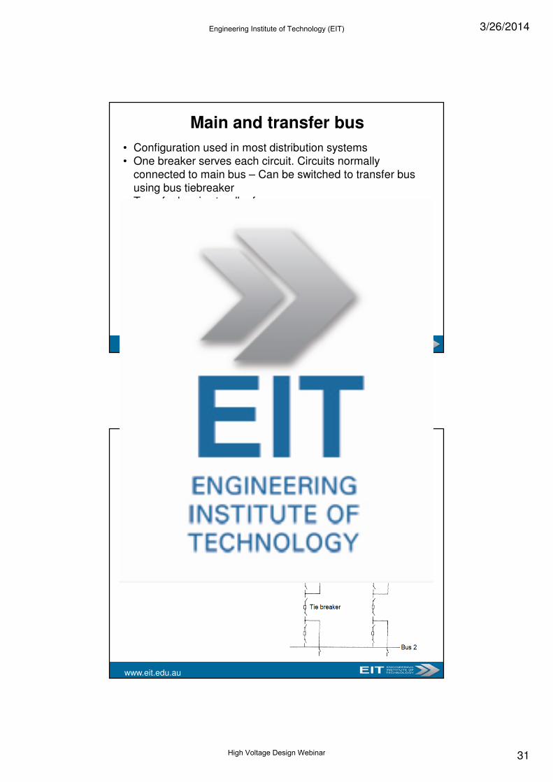
Main and transfer bus
• Configuration used in most distribution systems• One breaker serves each circuit. Circuits normally
connected to main bus – Can be switched to transfer bus using bus tiebreaker
• Transfer bus is standby for emergency purposes• Circuits on transfer bus not protected by breakers – Fault
on one transferred circuit results in outages for all transferred circuits
www.eit.edu.au
Breaker and a half
• Three series breakers connected between two buses
• All breakers are closed, two main buses energized under normal operating conditions
• Two associated breakers must be opened to trip circuit
• More expensive, but provides high reliability, maintainability and flexibility
• Protective relaying more complex
• Breakers, other system components rated for sum of load of two circuits
• High security against loss of supply
Engineering Institute of Technology (EIT)
High Voltage Design Webinar
3/26/2014
32
www.eit.edu.au
Ring busbar• Requires only one breaker per circuit - Economical
• Each outgoing circuit has two sources of supply, provides high reliability
• Practical up to five circuits
• Common to initially build a SS as ring bus, convert to breaker and a half when having more requirement
• Natural configuration for GIS applications with any number of circuits
• Protective relaying relatively complex
• Busbar fault causes all circuits to be lost until identified and isolated
• Maintenance of isolator requires outage of both adjacent circuits, unless isolators are duplicated
Thank You For Your InterestIf you are interested in further training, please visit:
The Engineering Institute of TechnologiesOnline Certificate and
Advanced Diploma programs:
www.eit.edu.au
IDC Technologies
1, 2 & 3 day practical workshops, technical manuals,
onsite training & International conferences:
www.idc-online.com
Engineering Institute of Technology (EIT)
High Voltage Design Webinar