high temperature superconductor lead assemblies for xrism · • high temperature superconductor...
TRANSCRIPT

National Aeronautics and Space Administration
CEC-ICMC
High Temperature Superconductor Lead Assemblies for XRISM
Edgar R. Canavan and Brian Comber
1 NASA – Goddard Space Flight Center
https://ntrs.nasa.gov/search.jsp?R=20190027702 2020-06-19T17:12:38+00:00Z

NASA — Goddard Space Flight CenterCEC-ICMC
Background: RESOLVE
LHe Tank(1.2 K)
ADRstages
Vacuum shell (~300 K)
Cryocooler(1 of 2)
Cooled shield (~28 K)
JT cooled shield(~4.5 K)
RESOLVE Thermal System:• (2x) 2 stage Stirling coolers• JT cooler (4.5 K)• 40 l LHe tank (1.2 K)• 3 stage ADR ( 50 mK )
Madison, WI, July 10–14, 2017 2
RESOLVE: soft x-ray spectrometer on XRISM (X-Ray Imaging and Spectroscopy Mission)
Rebuild of SXS instrument on Astro-H — no changes except where necessary
Uses a microcalorimeter array operating at 50 mK

NASA — Goddard Space Flight CenterCEC-ICMC
Background: HTS Lead Assemblies• High Temperature Superconductor Lead Assemblies necessary to carry high current to 3 ADR magnets
• Driving requirements:– 2 Amp maximum on each of 3 circuits @ up to 62 K warm end– < 12 µWatt total conducted heat leak to 1.3 K– < 10 µΩ per circuit total resistance at cold end (bolted and solder joints)
3Madison, WI, July 10–14, 2017

NASA — Goddard Space Flight CenterCEC-ICMC
HTS Lead Assemblies — Configuration
• Status– Engineering Model complete– Flight Model 1 fabricated and fully verified– Flight Model 2 fabricated; pre-vibe testing complete
4Madison, WI, July 10–14, 2017
Cold (1.2 K) transition board
Warm (< 62 K) transition board
JT (4.5 K) transition board
Bolted joints — transition to ADR magnet leads
Connector to current harness
3rd Stage Assembly 1st & 2nd Stage AssemblyJT heat strap
Warm (< 62 K) transition board

NASA — Goddard Space Flight CenterCEC-ICMC
Solder Joints: Material Changes• HTS tape
– SXS: AuAg alloy coated tape; slit to 1 mm after production (open sides)– RESOLVE:
• Slit to 1 mm, then sputter coated with AuAg (all sides)• Individual sections cut and plated over solder region with > 20 µm Cu• Section Ic’s measured to 20 Amperes:
– 37 of 48 long (590 mm), 21 of 24 short (335 mm) sections ≥ 20 A; – All Ic’s ≥ 16 A
• Solder – In3%Ag (SXS) ➔ In48%Sn (RESOLVE)
• Lower Tmelt (144 C ➔ 118 C)
5Madison, WI, July 10–14, 2017
NASA — Goddard Space Flight CenterCEC-ICMC
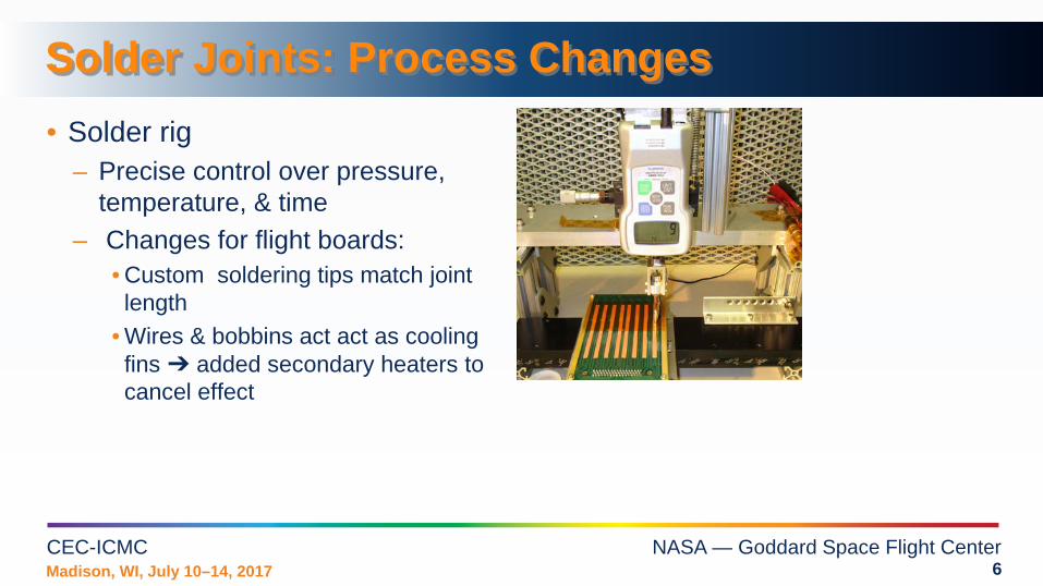
Solder Joints: Process Changes• Solder rig
– Precise control over pressure, temperature, & time
– Changes for flight boards:• Custom soldering tips match joint length
• Wires & bobbins act act as cooling fins ➔ added secondary heaters to cancel effect
6Madison, WI, July 10–14, 2017

NASA — Goddard Space Flight CenterCEC-ICMC
Solder Joints: Results• Improved Consistency:
– Compared all pre-vibe qualification tests: I-V measurement to 5 Amps, cold end at 4.5 K
– Cold end solder joint resistances much more uniform
– No values > 1.1 µΩ– Similar results for warm end (62 K)
• Very low resistance at low T– Bridge (low current) measurements show
transitions at ~5.0, ~3.7 K– Below 3.7 K, R < 0.4 µΩ
7Madison, WI, July 10–14, 2017
Histogram: Cold end jointsFlight units; pre-vibe tests

NASA — Goddard Space Flight CenterCEC-ICMC
Bolted Joints: Changes and Results
8Madison, WI, July 10–14, 2017
Metrology points [mm]
Bobbins: In-house Commercial
Cu material: 99.999% CU101
Au Plating Ni flash, Thick Au
No Ni flash,Standard thickness
Fabrication EDM, polished
Lathe
Metrology: rounded Flat,+ ridge Result: Bolted joint resistance now typically < 0.5 µΩat low T

NASA — Goddard Space Flight CenterCEC-ICMC
1st & 2nd Stage Thermal Intercept: Changes
Concern over stress concentration at JT thermal intercept
9Madison, WI, July 10–14, 2017
HTS tape
epoxy
Pyraluxheat strap
New strap design:
Multilayer Pyralux strap
Compliant bridge for each HTS tape
Each HTS tape bonded to small
flag on bridge
HTS tapes in 1st&2nd Stage unit must be well heat sunk to JT shield

NASA — Goddard Space Flight CenterCEC-ICMC
1st & 2nd Stage Thermal Intercept: Results• Measurement:
– Control TIVCS, TJT = TCSI
– Measure ∆QCSI vs TIVCS
• If strap conductance, 𝜅𝜅 → ∞– Ts = TJT = TCSI ➔
∆QCSI = Qs→CSI = 0• With imperfect strap:
10Madison, WI, July 10–14, 2017
TS
TIVCS TJT TCSI
QIVCSS QSCSI
QSJTQIVCS QJT QCSI
• 1-D Conduction-only model• For flight condition
(TIVCS = 28 K, TJT = 4.5 K, TCSI = 1.3 K), heat leak to CSI:

NASA — Goddard Space Flight CenterCEC-ICMC
Conclusions• HTS Lead Assemblies for RESOLVE instrument — largely rebuild, except• Solder joints:
– New tape and solder– Tighter solder process control– Result: much more consistent solder joint resistances
• Bolted joints:– Initial testing lead to change to commercial bobbins– Pre-assembly screening– Result: much more consistent and lower bolted joint resistances
• JT heat intercept:– New design eliminates concern over stress concentration– Improved thermal test apparatus allows determination of 1st & 2nd Stage parasitic conductance
• Overall, RESOLVE HTS lead assemblies meet their requirements with significantly better margin than the Hitomi/SXS units
Madison, WI, July 10–14, 2017 11