high temperature, short term tensile strength of …
TRANSCRIPT
HIGH TEMPERATURE, SHORT TERM TENSILE STRENGTH OF C6000/PMR-15 COMPOSITES
P.R. DIGlovannl and D. Paterson
Raytheon Company
Missile Systems Division
Tensile tests were conducted on 0° unldlrectlonally reinforced Cellon 6000
graphite fibers in PMR 15 polylmlde matrlx. Tensile strengths for coupons sub-
Jected to short and long term uniform temperatures were obtained. Thick coupons,
heated on one side to produce significant transient through thickness temperaturegradients, were tested and compared to the strength of specimens with uniform tem-perature distributions.
All coupons were radiantly heated and reached maximum test temperatures within
15 sec. Tensile loads were applied to the coupons after 15 sec of elevated temper-ature exposure. Loading rates were selected so that specimen failures occurred
within a maximum of 45 sec after reaching the test temperature. Results indicate
that significant tensile strength remains beyond the material post cure temperature.
BACKGROUND
Medium range tactical missile airframe components have historically been
designed with low cost metallic materials insulated by a variety of thermal protec-
tion coatings when flight regimes cause excessive aerodynamic heating of the struc-
ture. The major design considerations for missile body shells are strength,
stiffness, weight, minimum thickness to permit maximum internal packaging volume,and minimum unit cost in production. Aluminum airframe structures are limited to
moderate free flight Mach numbers due to the rapid reduction in strength at temper-atures above 600°F. High strength metallic airframe structures are more difficult
to manufacture and are subject to increasing material and fabrication costs. Abla-
tion or subliming thermal protection systems are costly, increase the net thickness
of components thereby resulting In constricted internal volume, and are susceptible
to damage during handling operations and aircraft captlve-carry.
The development of advanced continuous filament composite materials over thepast two decades has been mainly restricted to applications in the aircraft and
space technology areas and has used epoxy matrices which are limited to 250°F -
300°F for long term use. Polylmlde matrix materials have recently been developedwhich can sustain temperatures up to 600°F for long durations. The maturation of
graphlte/polylmlde composites, due to improved manufacturing technology and
increasing filament production, has contlnuously reduced hardware cost, stimulatingincreasing applications.
The unique aspects of graphlte/polylmlde materials such as tallorable thermalexpansions, stiffness and strength by appropriate selection of laminate orientation
are several characteristics important to the missile airframe designer. Thestrength data at elevated temperatures of most advanced composite materials has
been developed for aircraft applications which assume long term exposure at ele-vated temperature environments. Since many tactical missiles are characterized by
flight times of less than two minutes duration at higher than cure temperature,
advanced composite strength data obtained for long term high temperature exposure
25"/

ls potentially conservative for missile airframe applications. Therefore, a testprogram was conducted to determine if the strength of graphite/polylmide could beextended to temperatures up to gOO°F for short durations.
Two issues are being addressed as part of the short tlme hlgh temperaturestrength evaluatlon of-advanced composites. First, the evaluation of tensile
strengths of 0° unidirectional slx ply thick graphlte/polylmlde coupons when sub-
Jected to uniform through thickness transient temperatures for exposure times of
one minute or less. Second, the tensile strength evaluation of 20 ply thick 0°
graphlte/polylmlde coupons wherein significant through thickness temperature gradi-
ents existed. For the latter case, hlgh temperature exposure was limited to one
minute and maximum temperatures reached were the same as for the thin (slx ply)
test cases. The purpose of tests conducted during the existence of thermal gradl-
ents across the thick test coupon was to determine whether higher tensile strengthscould be achieved in those cases than for the uniform temperature case. When com-
paring strengths for both translent uniform and transient non-unlform coupon tem-perature histories, strengths for the non-unlform case were based on maximum face
temperatures, not average through thickness temperatures.
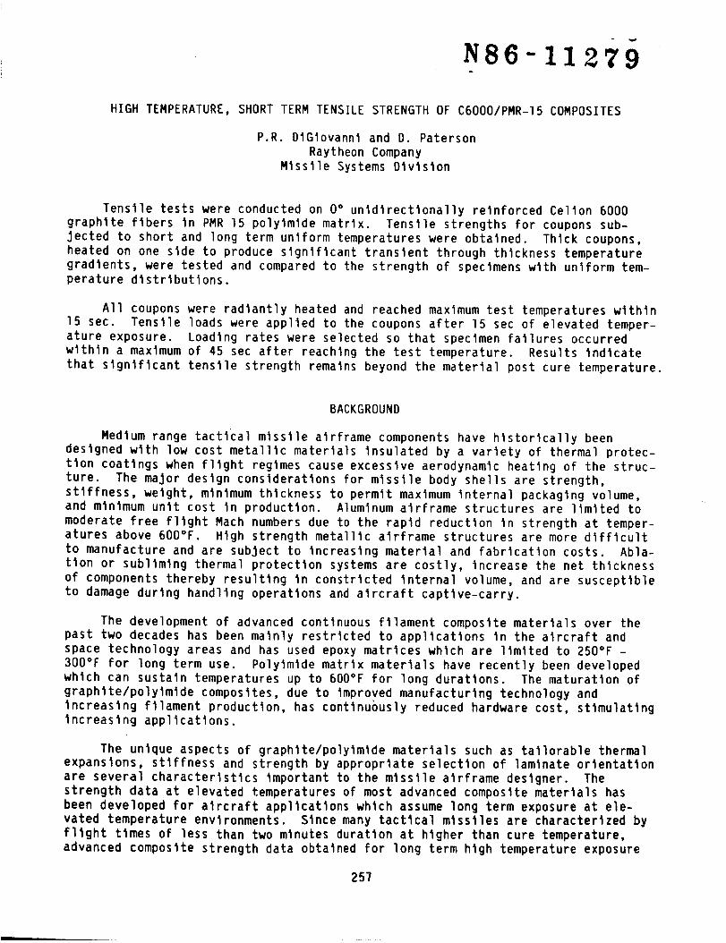
Shown In figure l, for tactical missiles, are typical ranges of maximum exter-
nal surface structural component temperature ranges, maximum through thickness tem-
perature differences, time to reach and tlme to maximum temperature, and totalflight times.
Ranges shown In figure 1 represented the bases for the tensile coupon testsconducted during the presently reported experimental study.
TEST SPECIMEN PREPARATION,INSTRUMENTATION, AND TEST PROCEDURE
Tensile test, straight edged, 0° unidirectional tabbed coupons were cut fromCellon 6000/PMR-15 panels fabricated by the Hamilton Standard Division of United
Technologies Corp., Windsor Locks, Ct. Slx ply and twenty ply panels, g In. xlO 3/4 In., were press-cured In heated ceramic platens. The six ply laminated
panels were used to provide uniform through thickness transient temperature testcoupons, while the thicker twenty ply laminated panels provided test coupons usedfor through thickness transient temperature gradient tensile tests. The unidirec-
tional panels were fabricated from Flberlte prepreg HY-E 1666AE, Lot CI-467. The
laminated panels were Imldlzed and cured following a procedure developed by Hamilton
Standard for fabrication of C6OO0/PMR-15 FlO0 engine nozzle flaps. The panels werepostcured at 600°F for 12 hrs. In an alr circulating oven.
Test coupon tab materials were fabricated using seven plies of 0o/90 ° 7781
fiberglass cloth/PMR-15 laminate for the slx ply 0° coupons and twenty plies of 0°
C6000/PMR-15 laminate for the thick twenty ply coupons. For the latter case, anadditional twenty ply C600O/PMR-15 panel was specifically fabricated to provide tab
material for the thick coupons. Tab lengths were l I/2 In. for both thin and thick
coupons and were bonded to the panels using PMR-15 adhesive for subsequent cuttinginto straight edged tensile coupon shape. Tab angles for all test coupons were
go °. Coupon widths were 0.5 in. nominal for thln (slx ply) and thick (20 ply) cou-
pons. Panel cutting was performed wlth diamond blades to ensure hlgh finishes oncoupon edge faces.
258
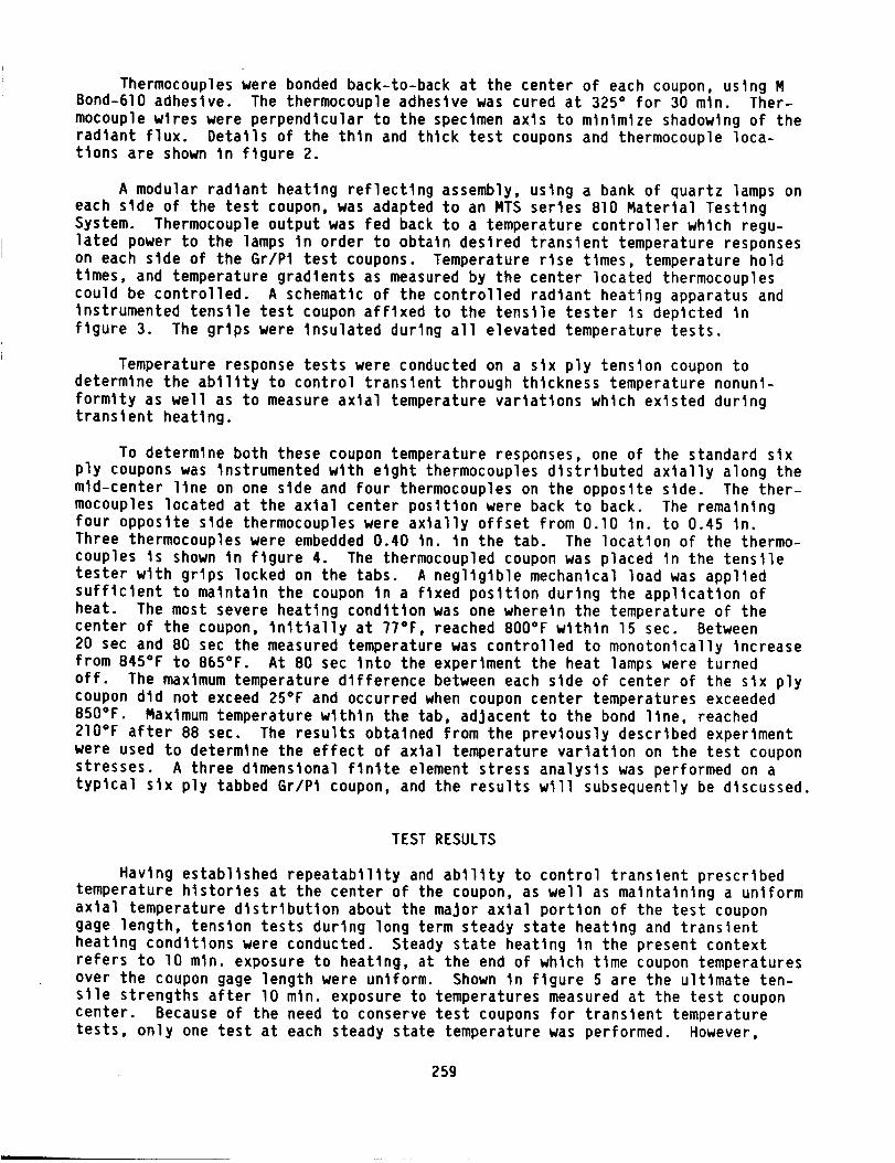
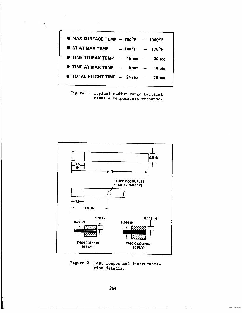
Thermocouples were bonded back-to-back at the center of each coupon, using MBond-610 adhesive. The thermocouple adhesive was cured at 325 ° for 30 mln. Ther-mocouple wires were perpendicular to the specimen axls to minimize shadowing of theradiant flux. Details of the thin and thick test coupons and thermocouple loca-tlons are shown In figure 2.
A modular radiant heating reflecting assembly, using a bank of quartz lamps oneach stde of the test coupon, was adapted to an MTS series 810 Material TestingSystem. Thermocouple output was fed back to a temperature controller which regu-lated power to the lamps in order to obtain desired transient temperature responseson each side of the Gr/Pt test coupons. Temperature rise times, temperature holdtimes, and temperature gradients as measured by the center located thermocouplescould be controlled. A schematic of the controlled radiant heating apparatus andinstrumented tensile test coupon affixed to the tensile tester Is depicted infigure 3. The grips were insulated during all elevated temperature tests.
Temperature response tests were conducted on a six ply tension coupon todetermine the abtllty to control transient through thickness temperature nonunl-formlty as well as to measure axial temperature variations which existed duringtransient heating.
To determine both these coupon temperature responses, one of the standard sixply coupons was instrumented with eight thermocouples distributed axially along themid-center line on one stde and four thermocouples on the opposite side. The ther-mocouples located at the axial center position were back to back. The remainingfour opposite side thermocouples were axtally offset from 0.10 In. to 0.45 In.Three thermocouples were embedded 0.40 In. tn the tab. The locatlon of the thermo-couples Is shown in figure 4. The thermocoupled coupon was placed in the tensiletester with grips locked on the tabs. A negligible mechanical load was appliedsufficient to maintain the coupon In a fixed position during the appllcatlon ofheat. The most severe heating condition was one wherein the temperature of thecenter of the coupon, lnltlally at 77°F, reached 800°F within 15 sec. Between20 sec and 80 sec the measured temperature was controlled to monotonically increasefrom 845°F to 865°F. At 80 sec Into the experiment the heat lamps were turnedoff. The maximum temperature difference between each side of center of the six plycoupon did not exceed 25°F and occurred when coupon center temperatures exceeded850°F. Maxlmum temperature within the tab, adjacent to the bond line, reached210°F after 88 sec. The results obtained from the previously described experimentwere used to determine the effect of axial temperature variation on the test couponstresses. A three dimensional ftnlte element stress analysis was performed on atypical stx ply tabbed Gr/Pt coupon, and the results wtll subsequently be discussed.
TEST RESULTS
Having established repeatability and ability to control transient prescribed
temperature histories at the center of the coupon, as well as maintaining a uniform
axial temperature distribution about the major axial portion of the test coupongage length, tension tests during long term steady state heating and transient
heating conditions were conducted. Steady state heating In the present context
refers to lO mln. exposure to heating, at the end of which time coupon temperatures
over the coupon gage length were uniform. Shown In figure 5 are the ultimate ten-
sile strengths after lO mln. exposure to temperatures measured at the test coupon
center. Because of the need to conserve test coupons for transient temperature
tests, only one test at each steady state temperature was performed. However,
259

while the tntttal set of stx ply 0 e coupons had observable tab offset (each side ofdifferent length) due to tntttal fabrication problems, four were tested at room
temperature conditions. Three of these four tests resulted tn an average ulttmatestress 203 ks1 with a spread of 4 ks1. The fourth coupon, with significant damagetn the stx ply regton at the edge of the tab, resulted In failure at the tab at astress of 172 ks1. An additional six ply panel was fabricated and the tab problemcorrected. No data from coupons obtatned from the problem tab panels Is pre-sented. Whtle the test data from the C6000/PRR-15 coupons exceeds that In refer-ence 1, It ts Important to note that two different 6r/Pt systems are compared Inthe results shown tn ftgure S. Also, the test coupon of (ref. 1) has a 4 In. gagesection and 2.5 tn. bevelled tabs. The Increase In strength from 750°F and 850°Fmay be Illusory because of the mtnlmum specimens tested, and/or post curingeffects. The former seems more 11kely since the 0° tensile strengths are fiberdominated.
In order to determine transient short term tensile strengths wtth uniformthrough thickness temperature distributions, six ply coupons were subjected to tem-perature histories as shown In ftgure 6. Loadtng was applied at a constant loadrate at 15 sec following start up of heating, and all coupons fatled wlthtn 40 sec.Assuming that the 0" tensile modulus Is never reduced below Sxl06 pst for a11short term temperatures to 850"F. max., thts results tn maximum strain rate durtngthe tests of 0.05 tn/tn-mtn.
The corresponding ultimate tensile strengths for short term untform throughthickness elevated temperatures are shown tn ftgure 7.
Three tenstle tests at each temperature were conducted as shown In figure 7.The primary results tndtcate that up to 850"F, approximately 70 percent of roomtemperature strength Is maintained for up to 40 sec. Failure stresses for the slxply coupons were between 199-205 ks1 at room temperature and between 125 and 165 ks1when sub3ected to short term 850"F transient temperatures. Relatively smoothstrength decreases were obtained for coupons subjected to temperatures between R.T.and 850"F. Unlike the steady state ulttmate strength behavior, significantstrength decrease ts apparent at 450"F, well below the post cure temperature of600"F. Strength continues to decrease with temperature to 750"F and then remainsconstant but wtth Increasing scatter to 8SO'F. This differs significantly from thesteady state O" tens11, strength variation up to matrix post cure temperatureexperienced by graphite/epoxies (ref. 1) and graphtte/polytmldes (ref. 2).
In order to determlne whether slgnlflcant strength Increases occur when hlghtranslent temperatures occur on only the external structural surfaces and largethrough thlckness thermal gradlents exlst due to low transverse thermal conduc-
tlvlty, translent temperature hlstorles were produced In thlck, [0"]20, couponsas shown In flgure 8.
As tn the case of [0"] 6 coupons, tenstle loads were applied to the thtckcoupons foil.wing 15 sec of heattng. After 20 sec of heattng the maximum tempera-ture on one side of the coupon was held constant while the temperature on thecooler stde continued to Increase. At 50 sec heating ceased and temperatures onboth stdes of the coupon Instantaneously decreased. For the thermal gradtent test,ulttmate tenstle stresses obtained for maxtmum coupon surface temperature of 650",750", 850" and gS0"F are shown tn ftgure g.
260

No significant increase In strength for coupons subjected to short term ther-mal gradients were observed when compared to the coupons subjected to short termuniform temperatures for the same maximum temperatures. Even when the short termthermal gradient strength data ts compared to strengths obtained for long term tem-perature subjected coupons (figure 5), no significant increase In tensile strengthIs observed. (However, sufficient analysis has not been conducted to determinewhether longer end tabs should be used for 20 ply straight coupons and If a uniformuntaxtal state of stress exists tn the gage section of 9 in. thick coupons.) Thelow value of room temperature ulttmate stress, as shown In figure 9, for the
[0"]20 tensile specimen compared to the [0"] 6 specimen suggests at least a fur-ther investigation Into the stress state In thick tenstle coupons. Also, it shouldbe noted that 5 percent less fiber volume was measured in the thick 20 ply panelthan tn the thin stx ply panel from which the test coupons providing the data tnquestion were obtained (both fiber volume measurements were obtained from one ran-dom sample of each panel).
THREE DIMENSIONAL FINITE ELEMENT
IDEALIZATION OF THERMAL STRESS EFFECTS
To better understand the effect of axial thermal gradlents In the [0°]6Gr/PI test coupon, the test coupon including end tabs and adheslve were analyzedusing the finite element idealization.
Symmetry of the test coupon enables the stress analysis to be performed usingone-elghth of the coupon. The analysis Is based on a 20 node Is,parametric ortho-
tropic brick element using the SAPV Structural Analysis Program (ref. 3). The
finite element model represents a 6 laminae 0° unidirectional Gr/PI end tab, a
0.002 in. PMR-15 adhesive layer, and a 6 laminae 0° unidirectional Gr/PI specimen.
The end tab was modeled using three elements (two laminae) In the thicknessdirection, the adhesive layer by one element In the thickness direction, and the
test specimen by 6 elements In the thickness direction, one for each lamina. Thewidth of the elements was reduced In the tab end region In the axial direction of
the center of the test coupon. It Is assumed that the test coupon Is stress free
at the post cure temperature of 600°F. The detailed finite element geometricalmodel Is shown In figure lO. The tab and adhesive element widths are 0.05 in. In
the tab/speclmen region and increase to 0.25 In. for the remainder of the tab. The
specimen element width Is O.l In. and increases to 0.5 In. for the remainder of the
specimen length.
The measured temperature distribution for the [0"] 6 ply coupon at 25 secafter heating Is shown In figure II. Through thickness variations were small andneglected In the flnlte element analysis.
Material properties used In the flnlte element analysis are given below:
Graphlte/Polylmlde Specimen (refs. 4 and 5)
Ell = 20xlO 6 psl E22 = E33 = 1.2xlO 6 psl
612 . 613 = 623 ,, lxlO 6 pst
u12 = u13 - u23 = 0.33
261

=11 = 1x10⁻⁷ ln/ln-°F
=22 = =33 = 1.44 x 10 -5 ln/tn-°F at 70°F
a22 = a33 = 1.58 x 10 -5 ln/ln-°F at 300°F
=22 = a33 = 1.15 x 10 -5 ln/ln-°F at 900°F
PRR-15 Adhesive (ref. 6)
E = 0.47 x 10⁶ pst
G = 0.17 x 10⁶ psi
u = 0.36
= 28 x 10 .6 ln/ln-°F
The Important results for calculated stresses are shown tn figure 12. Recallthat the stresses calculated are due solely to steady temperature distributionmeasured experimentally. The stress free state was assumed to exist at the postcure temperature of 600°F.
The maximum transverse coupon normal stress distribution Indicates failure ofthe matrix between fibers In the tab region. Examinat_on of the temperature dis-tribution (figure 11) shows that coupon temperatures are below 200°F. Since thetab ts fixed on the outer face, the large transverse tensile stress Is In responseto constraining the coupon contraction. At the stress level predicted severemlcrocracklng would have been Initiated leading to a redistribution of transversestress. Since the tenstle tests are ftber dominated, no significant effect of thetransverse cracking on the 0 ° tensile would be expected If damage between thematrix and fiber surface also does not result. The early strength decrease w_thtemperature as shown In figure 7 may be an Indication of early fiber/matrix inter-face failure. Further experimentation and photomlcrographlc exam_natlon of sec-tioned tab region Is Indicated to better understand the failure mechanism underelevated temperature htghly transient environments.
CONCLUDING REMARKS
Tenstle tests at transient elevated temperatures on [0°]6 Cellon 6000/PRR-15graphite polytmlde material for maximum temperatures up to 850°F were conducted.It was shown that controlled quartz heat lamps can provide near untform throughthickness temperature distributions for 60-70 sec for stx ply coupons. Thick,20 ply 0 ° coupons were used to provide controlled maximum surface temperature andprescribed transient temperature gradients.
During untform through thickness transient temperature tests, 0° strengthdecreased moderately at 450°F, whtle 70 percent of the room temperature strengthexisted for peak transient temperature up to 850°F. Tenstle strengths up to 115 kslwere obtained for 20 ply 0 ° coupons when the outer surface maximum temperaturereached 950°F in less than one m_nute. A three d_mens_onal f_ntte element analysisof a [0°]6 heated coupon, exhibiting a significant axial thermal gradient, Indi-cated high transverse tensile normal stress In the tab region of the tenstle cou-pon. Finally, In order to better understand failure of thick unidirectional
262

coupons subjected to short term through thickness and axtal temperature gradients,a detailed stress and thermal analysls should be further studied to determine edgeand thickness effects and to establish an optimum tensile coupon configuration.
REFERENCES
1. Hofer, K.E., 3r.; Larsen, D.; Humphreys, V.E.: Development of Engineering Dataon the Mechanical and Physical Properties of Advanced Composite Materials.AFML-TR-74-266, 1975.
2. Kerr, J.R.; Hasklns, 3.F.: Time-Temperature-Stress Capabilities of CompositeMaterials for Advanced Supersonic Technology Application - Phase I. NASACR-159267, 1980.
3. SAPV2: A Structural Analysis Program for Static and Dynamic Response of LinearSystem USC, Dept. of Civil Eng'g. Los Angeles, 1977.
4. Campbell, M.D.; Burleigh, D.D.: Thermophyslcal Properties Data on Graphite/
Polylmlde Composite Materials: NASA CR-15g164, 1979.
5. McCleskey, S.F.; Cushman, 3.B.; Skoumal, D.E.: Hlgh Temperature Composites forAdvanced Missiles and Space Transportation Systems. AIAA Paper No. 82-0707,
1982. Also in Proc, AIAA/ASME/ASCE/AHS 23rd Structures, Structural Dynamics and
Materials Conf., May 1982, pp. 212-222.
6. Hanson, M.P.; Chamls, C.C.: Graphite Polylmlde Composite for Application to
Aircraft Engines. NASA TN-D-7698, 1974.
263
• MAX SURFACE TEMP - 750°F - 1000°F
• AT AT MAX TEMP - 100°F - 175°F
• TIME TO MAXTEMP - 15sec - 30set
• TIME AT MAXTEMP - 0sec - 10sec
• TOTAL FLIGHT TIME - 24sec - 70sec
Figure i Typical medium range tacticalmissile temperature response.
±
II I Io "THERMOCOUPLES
//(BACi'TO'BACK)
_'---_ 4.5 IN-_'--"_
0.05 IN
0.05 IN i
THIN COUPON(6 PLY)
0.146 IN
0.146 IN i
TTHICK COUPON
(20 PLY)
Figure 2 Test coupon and instrumenta-tion details.
264

INSULATED LOADGRIPS
CONTROLLER[_ I POWER
-I_ INPUT
I JAWS
CONTROLLER
INPUT
Figure 3 Transient heating/tensileloading schematic.
0.70
THERMOCOUPLE
0.00
1.22
1.50
_' 1.80UJ
2.30Z
1.65
2.10
2.40
3.25
4.50
Figure 4 Thermocoupled test coupon(6 ply - 0°).
255

<aRAYTHEON DATA (CELION 6000/PMR-15)
220|1"- <t - 10 MIN. EXPOSURE
='v_ 180 - <i
160 --
r-; _ 140 - o BEE.2 DATA(HTS/710)
00 I I I I I I I I I100 200 300 400 500 600 700 800 900TEMPERATURE (OF)
Figure 5 Long term uniform temReraturetensile strength of 0v Gr/Pi.
900
SOO
700
600
4OO
3oo
UNIFORM TEMPm
2OO
100
0
STARTLOAD
/
I _ I I I I I10 20 30 40 50 60
TIME (sec)
Figure 6 Transient temperature histories
for 0° 6 ply tensile coupons.
255

220--[00]6CELION6000/PMR-15
uJ•.J ..,. 200_'_Z_
18ouuc.9I- z'¢ uJ 160=Ea:
_ _ 140
120
B
I 1 I I I I I I I0 100 200 300 400 500 600 700 800 900
TEMPERATURE (° F)
Figure 7 Short term uniform temperature
tensile strength.
TEMP GRADIENT90O
800
700
600
_ 400
200 _-// TMA x = 850oFIII
100 _r START
I "7°0 10 20 30 40 50 60
TIME (sec}
Figure 8 Transient temperature history
for [00]20 coupons.
26"/

' :::F ,oo,2oCEL,o,8ooo/PMR-lS
_ 14o-120 --
®
100 I I I I I I I I I I0 100 200 300 400 500 600 700 800 900 1000
TEMPERATURE (OF)
Figure 9 Short term thermal gradient
tensile strength.
z 0.25IN---//-- -//---0.05 iN
E'OT'BII"ADHESIVE -_
SPECIMEN illl/ /y"
///
-X
Figure i0 F.E. idealization of test
coupon.
268

°_v1000 L
_600_ _
o) = i ;I ; ;<l: 0 1.0 2.0 3.0 4.0 5.0
£ x
Figure ii Temperature versus axial position along [0°]6temperature gradient.
for maximum axial
'"1-_ VI Q°x"_X_°°"°"-i°o°12 I A I ® oy MAX/COUPON I
)_ _'_'_ _I(_)(_ r MAX/BOND1 0"4
,o -1<,., _
o-"" 'lff- ........--t"_"o'it/ _ 1 -°'__" 'U Ik_ -°°o="- °_-°" i
-20 1.0 2.0 3.0 4.0 4.5
Figure 12 Maximum stress distributions in coupon, bond line, and end tab dueto heating (stress free temperature - 600°F),
269