high-temperature alkaline water electrolysis · 2019-04-24 · relevance overall project objectives...
TRANSCRIPT

2019 DOE H2 and Fuel Cell Annual Merit Review Meeting
High-Temperature Alkaline
Water Electrolysis
Hui Xu (PI) and Kailash Patil
Giner Inc.
Prabhakar Singh
University of Connecticut
Project # May 1, 2019 P143
This presentation does not contain any proprietary, confidential, or otherwise restricted information
Project Overview
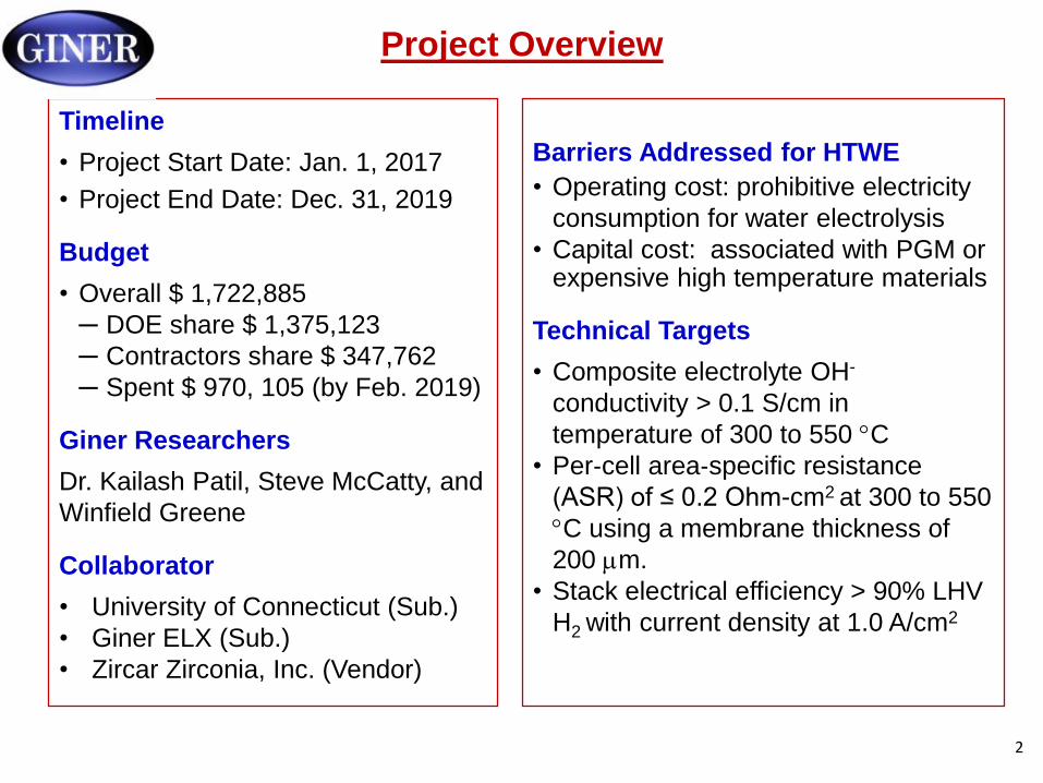
Timeline
• Project Start Date: Jan. 1, 2017
• Project End Date: Dec. 31, 2019
Budget
• Overall $ 1,722,885
─ DOE share $ 1,375,123
─ Contractors share $ 347,762
─ Spent $ 970, 105 (by Feb. 2019)
Giner Researchers
Dr. Kailash Patil, Steve McCatty, and
Winfield Greene
Collaborator
• University of Connecticut (Sub.)
• Giner ELX (Sub.)
• Zircar Zirconia, Inc. (Vendor)
Barriers Addressed for HTWE
• Operating cost: prohibitive electricity
consumption for water electrolysis
• Capital cost: associated with PGM or expensive high temperature materials
Technical Targets
• Composite electrolyte OH-
conductivity > 0.1 S/cm in
temperature of 300 to 550 C
• Per‐cell area‐specific resistance
(ASR) of ≤ 0.2 Ohm-cm2 at 300 to 550
C using a membrane thickness of
200 m.
• Stack electrical efficiency > 90% LHV
with current density at 1.0 A/cm2 H2
2

Relevance
Overall Project Objectives
To develop high-temperature alkaline electrolysis using molten hydroxides in porous metal oxide matrix
FY 2018-19 Objectives
Develop electrolyte support metal oxide matrix
Evaluate the matrix materials stability in hydroxide electrolyte at 400-550 °C.
Demonstrate single cell performance <1.5 V at 1,000 mA/cm2 at temperature <550 °C.
Reduced the electrolyzer cell temperature of 550 °C to 450 °C.
Impact
Reduce the capital and operating costs of water electrolysis to meet DOE goals and to make water electrolysis
more viable and competitive against other technologies
DOE: Distributed Forecourt Water Electrolysis
Feedstock costs (electricity) consists of 50% of total cost
High-temperature electrolysis offers the advantage of lower energy requirements due
to both faster kinetics and greatly reduced equilibrium voltages
3

Technical Approaches
Major Advantages
Flexible temperatures-
intermediate T compared to PEM
and SO system)
Less expensive materials
Key to Success
Porous metal oxide matrices resistant to
molten hydroxides
Microstructures of the porous oxide matrices
determine whether they can successfully
retain molten hydroxides
- thickness, porosity and pore structures
4
Task
No.
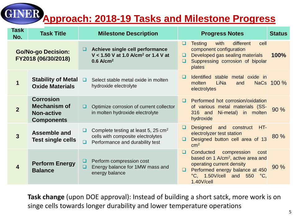
1 Stability of Metal
Oxide Materials Select stable metal oxide in molten
hydroxide electrolyte
Identified stable metal oxide in
molten LiNa and NaCs
electrolytes 100 %
2
Corrosion
Mechanism of
Non-active
Components
Optimize corrosion of current collector
in molten hydroxide electrolyte
Performed hot corrosion/oxidation
of various metal materials (SS-
316 and Ni-metal) in molten
hydroxide
90 %
3 Assemble and
Test single cells
Complete testing at least 5, 25 cm2
cells with composite electrolytes
Performance and durability test
Designed and construct HT-
electrolyzer test station
Designed button cell area of 13
cm2
80 %
4 Perform Energy
Balance
Perform compression cost
Energy balance for 1MW mass and
energy balance
Conducted compression cost
based on 1 A/cm2 , active area and
operating current density
Performed energy balance at 450
°C, 1.50V/cell and 550 °C,
1.40V/cell
90 %
Approach: 2018-19 Tasks and Milestone Progress
Task Title
o-go Decision:
(06/30/2018)
Milestone Description Progress Notes Status
Go/N
FY2018
Achieve single cell performance
V < 1.50 V at 1.0 A/cm2 or 1.4 V at
0.6 A/cm2
Testing with different cell
component configuration
Developed gas sealing materials
Suppressing corrosion of bipolar
plates
100%
Task change (upon DOE approval): Instead of building a short satck, more work is on singe cells towards longer durability and lower temperature operations
5
- - -
LiOH-NaOH
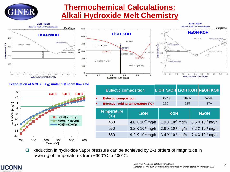
Thermochemical Calculations: Alkali Hydroxide Melt Chemistry
Evaporation of MOH (l g) under 100 sccm flow rate
LiOH-KOH NaOH-KOH
Eutectic composition LiOH NaOH LiOH KOH NaOH KOH
Eutectic composition 30-70 18-82 52-48
Eutectic melting temperature (°C) 220 225 170
0
LiOH(l) = LiOH(g)
NaOH(l) = NaOH(g)
KOH(l) = KOH(g)
650˚C 550˚C 450˚C
200 300 400 500 600 700
-2
-4
-6
-8
Log
P M
OH
(m
g/h
)
-10
-12
Temperature
(°C) LiOH KOH NaOH
450 4.0 X 10⁻⁷ mg/h 1.9 X 10⁻⁶ mg/h 5.6 X 10⁻⁶ mg/h
550 3.2 X 10⁻⁵ mg/h 3.6 X 10⁻⁵ mg/h 3.2 X 10⁻⁴ mg/h
650 9.2 X 10⁻⁴ mg/h 3.4 X 10⁻⁴ mg/h 7.4 X 10⁻³ mg/h -14
-16
Temp (°C)
Reduction in hydroxide vapor pressure can be achieved by 2-3 orders of magnitude in
lowering of temperatures from ~600°C to 400°C.
Data from FACT salt databases (FactSage) Conference: The 13th International Conference on Energy Storage Greenstock 2015
6
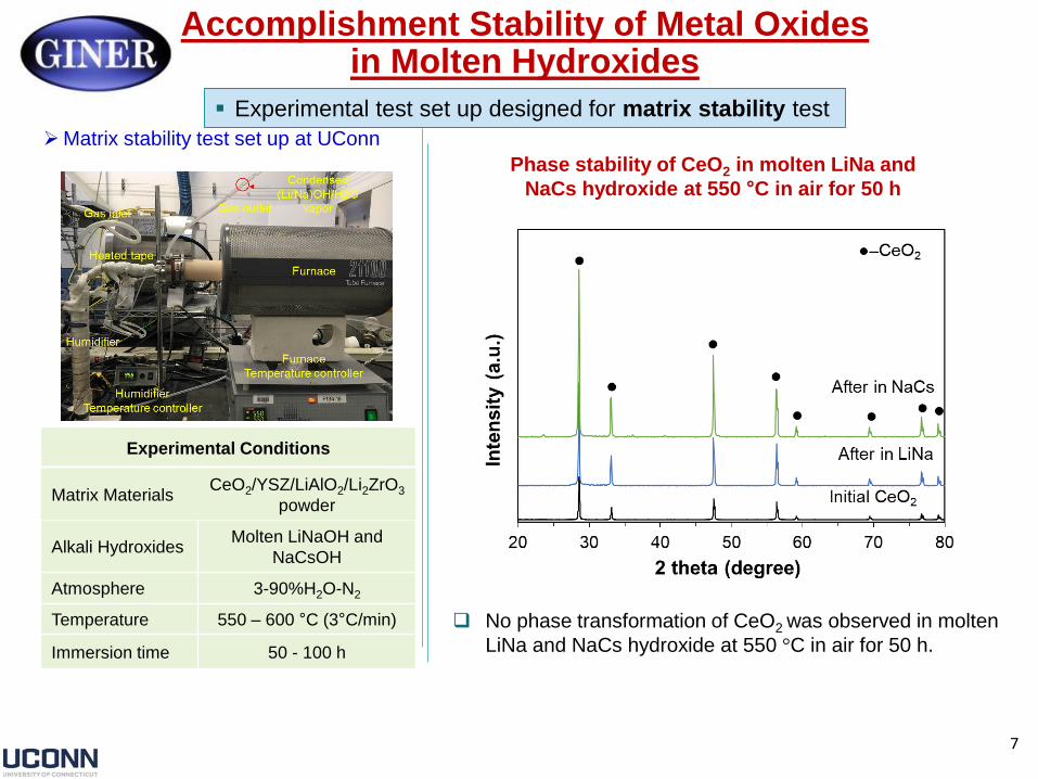
Accomplishment Stability of Metal Oxides in Molten Hydroxides
Experimental test set up designed for matrix stability test
Matrix stability test set up at UConn
Phase stability of CeO2 in molten LiNa and
NaCs hydroxide at 550 °C in air for 50 h
Experimental Conditions
CeO2/YSZ/LiAlO2/Li2ZrO3 Matrix Materials powder
Molten LiNaOH and Alkali Hydroxides
NaCsOH
Atmosphere 3-90%H2O-N2
Temperature 550 – 600 °C (3°C/min) No phase transformation of CeO2 was observed in molten
LiNa and NaCs hydroxide at 550 °C in air for 50 h. Immersion time 50 - 100 h
7
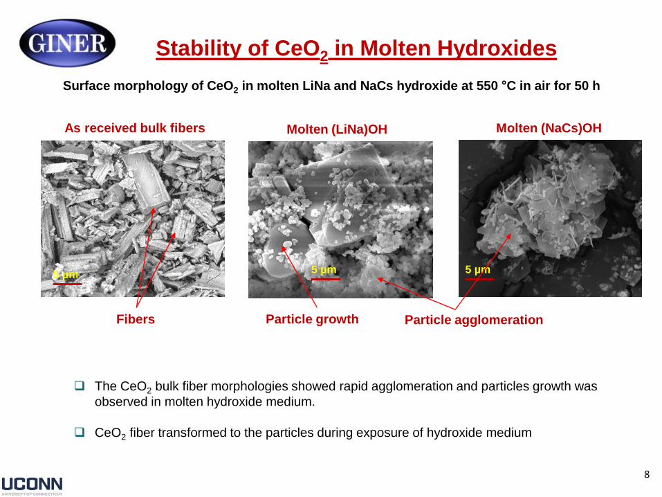
Stability of CeO2 in Molten Hydroxides
Surface morphology of CeO2 in molten LiNa and NaCs hydroxide at 550 °C in air for 50 h
As received bulk fibers Molten (LiNa)OH Molten (NaCs)OH
5 µm 5 µm 5 µm
Fibers Particle growth Particle agglomeration
The CeO2 bulk fiber morphologies showed rapid agglomeration and particles growth was
observed in molten hydroxide medium.
CeO2 fiber transformed to the particles during exposure of hydroxide medium
8
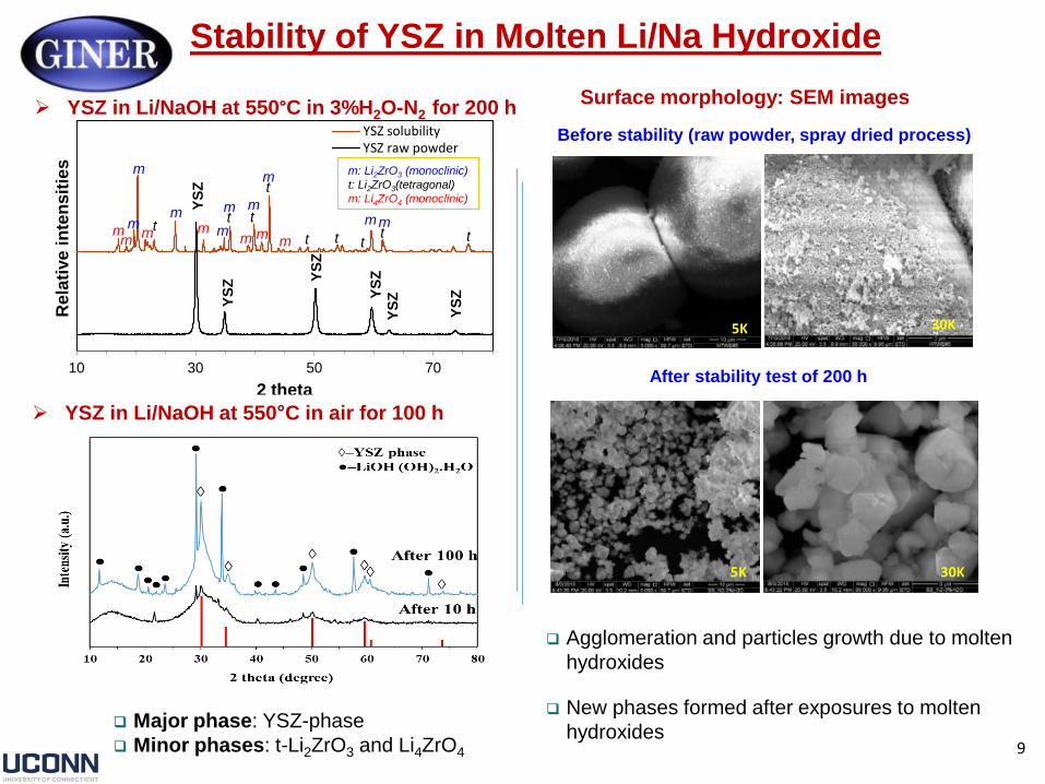
Stability of YSZ in Molten Li/Na Hydroxide
YSZ in Li/NaOH at 550°C in 3%H2O-N2 for 200 h
10 30 50 70
Rela
tive
in
ten
sit
ies
YSZ solubility YSZ raw powder
m
m
m m m t
t t
m t
t t t
m t t m
m m m m m m m
m Y
SZ
m: Li2ZrO3 (monoclinic)
t: Li2ZrO3(tetragonal)
m: Li4ZrO4 (monoclinic)
YS
Z YS
Z
YS
Z
YS
Z
YS
Z
2 theta
YSZ in Li/NaOH at 550°C in air for 100 h
Major phase: YSZ-phase
Minor phases: t-Li2ZrO3 and Li4ZrO4
Surface morphology: SEM images
Before stability (raw powder, spray dried process)
5K 30K
After stability test of 200 h
5K 30K
Agglomeration and particles growth due to molten
hydroxides
New phases formed after exposures to molten
hydroxides 9
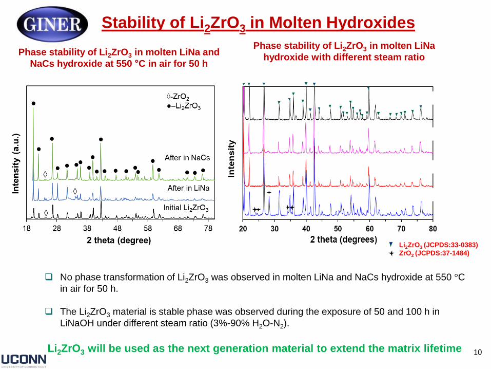
Stability of Li2ZrO3 in Molten Hydroxides
Phase stability of Li2ZrO3 in molten LiNa Phase stability of Li2ZrO3 in molten LiNa and
hydroxide with different steam ratio NaCs hydroxide at 550 °C in air for 50 h
As received powder
N2 -3%H2O after 50 h 550 °C
N2 -90%H2O after 50 h at 550 °C
N2 -3%H2O after 100 h at 600 °C
Li2ZrO3 (JCPDS:33-0383)
ZrO2 (JCPDS:37-1484)
No phase transformation of Li2ZrO3 was observed in molten LiNa and NaCs hydroxide at 550 °C
in air for 50 h.
The Li2ZrO3 material is stable phase was observed during the exposure of 50 and 100 h in
LiNaOH under different steam ratio (3%-90% H2O-N2).
Li2ZrO3 will be used as the next generation material to extend the matrix lifetime 10

Stability of Li2ZrO3 in Molten Hydroxides
Surface morphology of Li2ZrO3 after stability test: SEM images
As received powder (LiNa)OH at 550 °C for 50 h in air (NaCs)OH at 550°C for 50 h in air
10 µm 10 µm 10 µm
at 550 °C for 50h Accelerated test
LZO in
Molten (Li/Na)OH
10 µm 10 µm
at 600 °C for 100h
10 µm
3%H2O-N2 3%H2O-N2 90%H2O-N2
Li2ZrO3 powder remains unchanged during exposure to higher steam content and at higher temperatures.
No significant changes in the particle size and morphology were observed.
Li2ZrO3 will be used as the next generation material to extend the matrix lifetime 11
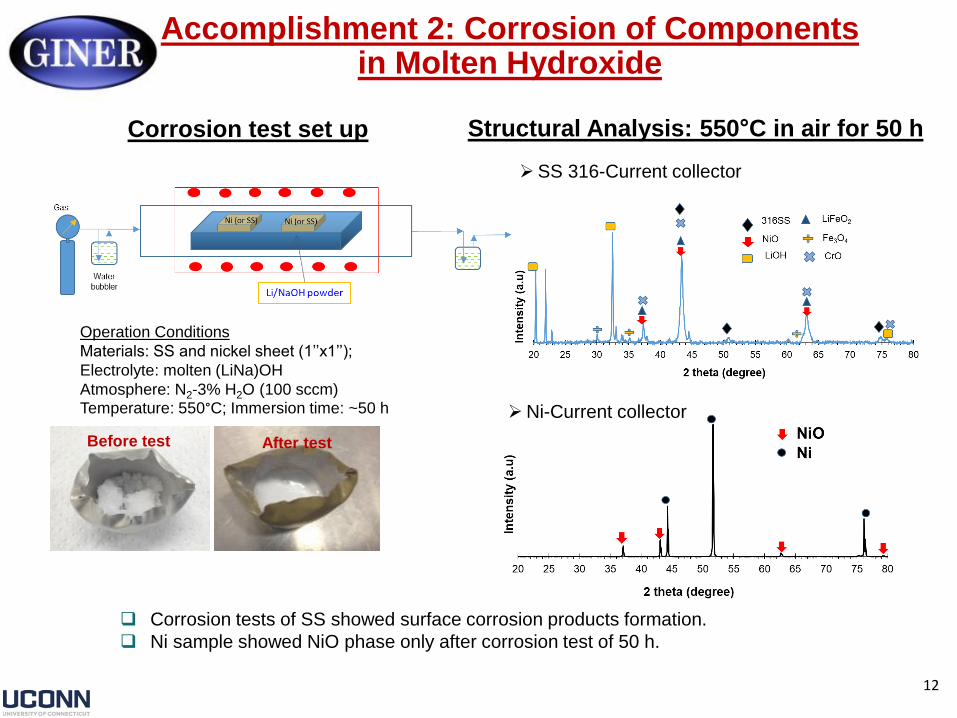
Accomplishment 2: Corrosion of Components in Molten Hydroxide
Corrosion test set up Structural Analysis: 550°C in air for 50 h
SS 316-Current collector
Ni-Current collector
Operation Conditions
Materials: SS and nickel sheet (1’’x1’’);
Electrolyte: molten (LiNa)OH
Atmosphere: N2-3% H2O (100 sccm) Temperature: 550°C; Immersion time: ~50 h
Before test After test
Corrosion tests of SS showed surface corrosion products formation.
Ni sample showed NiO phase only after corrosion test of 50 h.
12

Hot Corrosion Test: 316L SS-in Li/Na Hydroxide
Test Condition: N2-3%H2O at 450 and 550°C for 50 h.
450°C 550°C As received
Formation of mixed oxide scales (LiFeO2, LiFe5O8) with faceted morphology could be
spontaneously produced in Li/NaOH electrolyte due to its negative Gibbs energies.
13

Hot Corrosion Test: Ni-Metal in Li/Na Hydroxide
Test Condition: N2-3%H2O at 450 and 550°C for 50 h.
550°C 450°C As received
At 550 ℃, nickel was oxidized to form
NiO phase on the surface and the
NiO peaks increase in a higher
temperature.
Lowering temperature to 450 ℃ can mitigate hot corrosion
tremendously
- No NiO observed from XRD
14
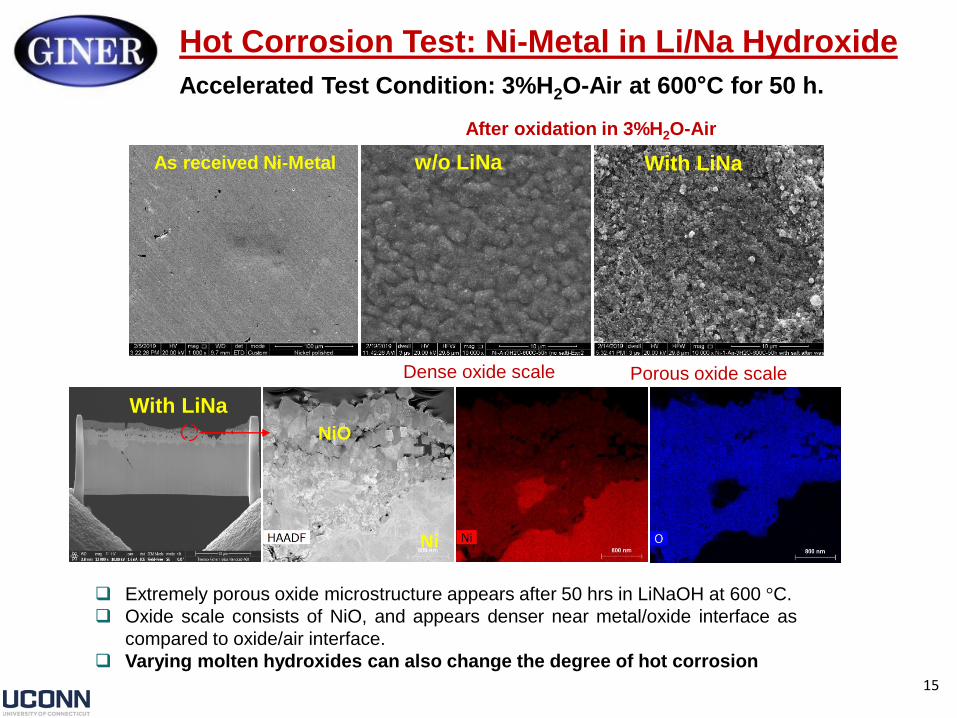
Hot Corrosion Test: Ni-Metal in Li/Na Hydroxide
Accelerated Test Condition: 3%H2O-Air at 600°C for 50 h.
After oxidation in 3%H2O-Air
As received Ni-Metal w/o LiNa With LiNa
Dense oxide scale Porous oxide scale
With LiNa
Ni
NiO
Extremely porous oxide microstructure appears after 50 hrs in LiNaOH at 600 °C.
Oxide scale consists of NiO, and appears denser near metal/oxide interface as
compared to oxide/air interface.
Varying molten hydroxides can also change the degree of hot corrosion
15
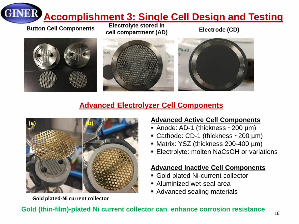
Accomplishment 3: Single Cell Design and Testing Electrolyte stored in
Button Cell Components Electrode (CD) cell compartment (AD)
Advanced Electrolyzer Cell Components
Advanced Active Cell Components
Anode: AD-1 (thickness ~200 µm)
Cathode: CD-1 (thickness ~200 µm)
Matrix: YSZ (thickness 200-400 µm)
Electrolyte: molten NaCsOH or variations
Advanced Inactive Cell Components
Gold plated Ni-current collector
Aluminized wet-seal area
Advanced sealing materials
Gold (thin-film)-plated Ni current collector can enhance corrosion resistance
Gold plated-Ni current collector
(a) (b)
16
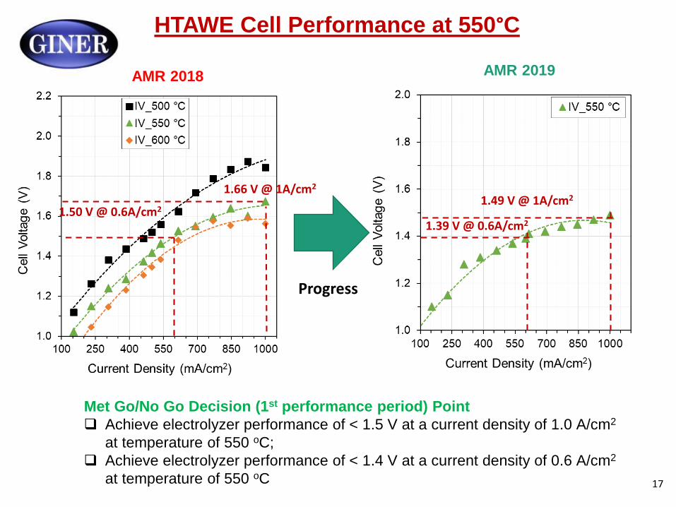
HTAWE Cell Performance at 550°C
AMR 2019 AMR 2018
1.39 V @ 0.6A/cm2
1.49 V @ 1A/cm2
1.50 V @ 0.6A/cm2
1.66 V @ 1A/cm2
Progress
Met Go/No Go Decision (1st performance period) Point
Achieve electrolyzer performance of < 1.5 V at a current density of 1.0 A/cm2
at temperature of 550 oC;
Achieve electrolyzer performance of < 1.4 V at a current density of 0.6 A/cm2
at temperature of 550 oC 17

Constructed Automatic Electrolyzer Test Station
Old Test Station New Test Station
Use nitrogen as a carrier gas in No nitrogen as a carrier gas
order to deliver reactants Industrial controller to continuously
Manually refill the boiler, and monitor cell conditions
regulate steam flow rates and Automatically refill the boiler, and regulate
temperatures steam flow rates and temperatures
Ability to produce up to 1.7kg/h of pure
steam at atmospheric pressure
18
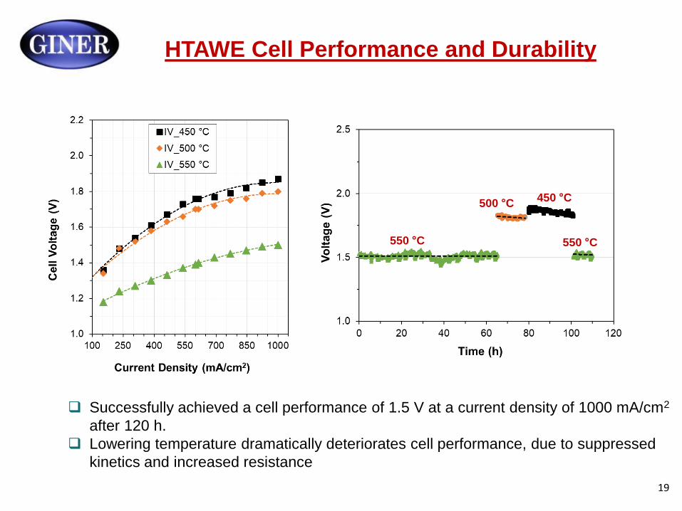
HTAWE Cell Performance and Durability
550 °C
450 °C
550 °C
500 °C
Successfully achieved a cell performance of 1.5 V at a current density of 1000 mA/cm2
after 120 h.
Lowering temperature dramatically deteriorates cell performance, due to suppressed
kinetics and increased resistance
19
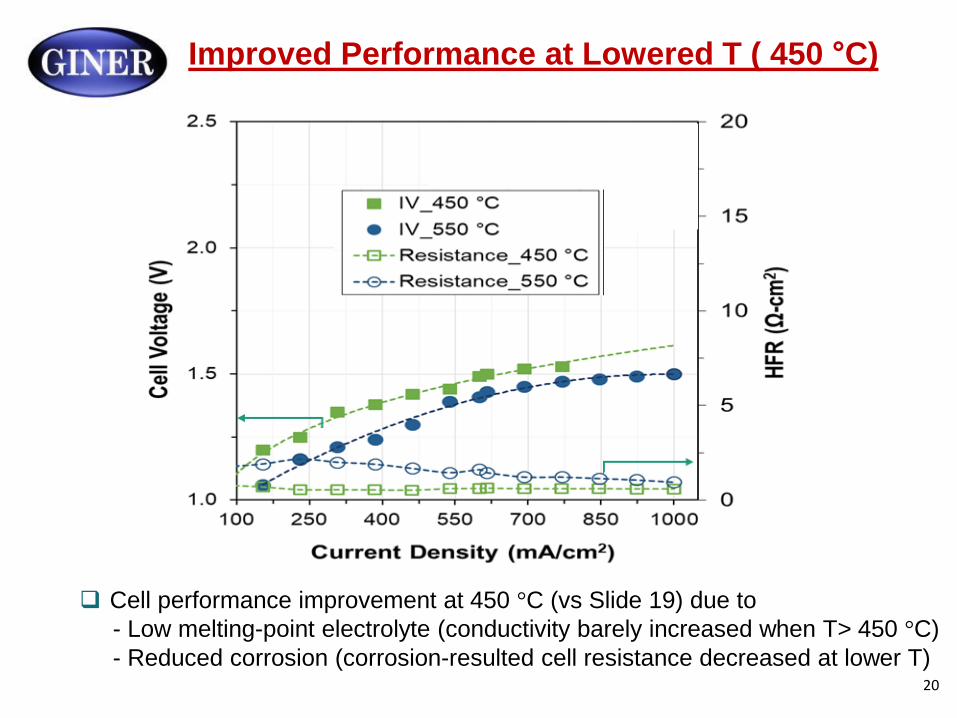
Improved Performance at Lowered T ( 450 °C)
Cell performance improvement at 450 °C (vs Slide 19) due to
- Low melting-point electrolyte (conductivity barely increased when T> 450 °C)
- Reduced corrosion (corrosion-resulted cell resistance decreased at lower T) 20
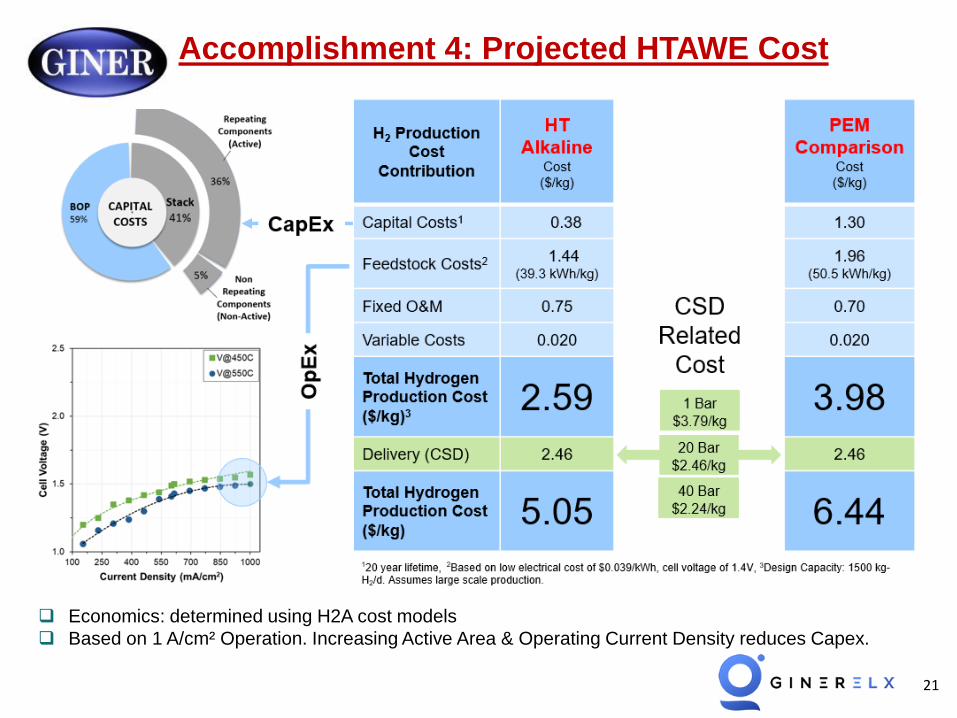
Accomplishment 4: Projected HTAWE Cost
Economics: determined using H2A cost models
Based on 1 A/cm² Operation. Increasing Active Area & Operating Current Density reduces Capex.
21
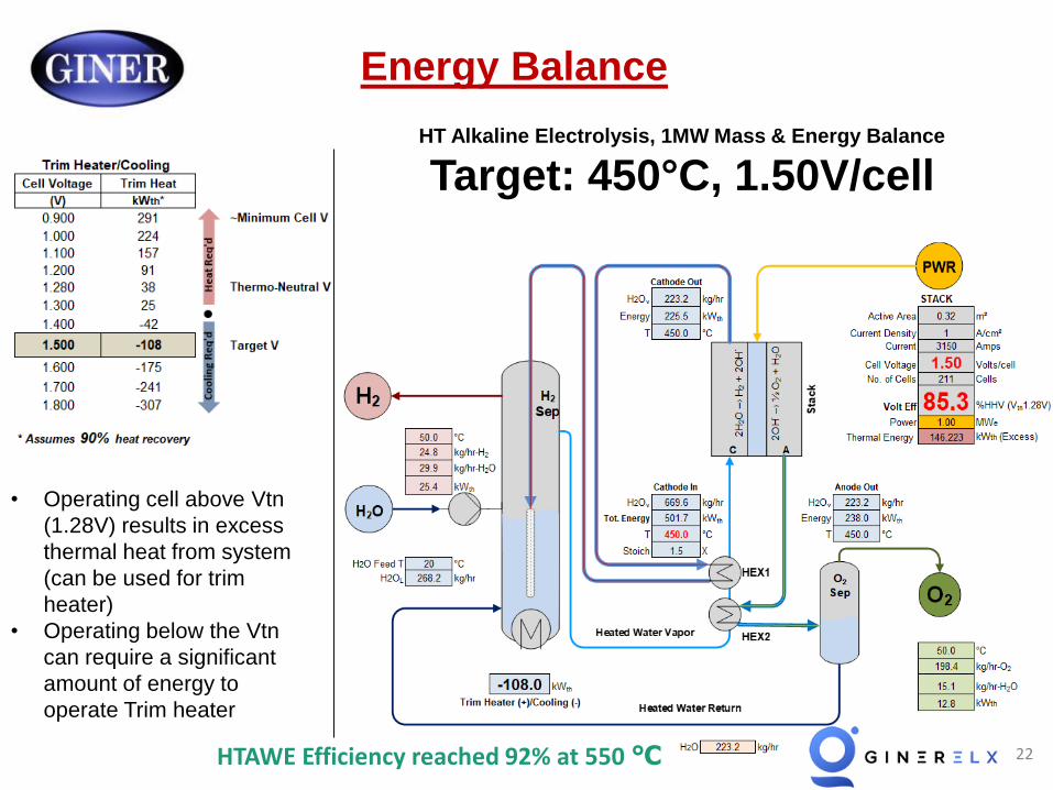
Energy Balance
HT Alkaline Electrolysis, 1MW Mass & Energy Balance
Target: 450°C, 1.50V/cell
• Operating cell above Vtn
(1.28V) results in excess
thermal heat from system
(can be used for trim
heater)
• Operating below the Vtn
can require a significant
amount of energy to
operate Trim heater
22 HTAWE Efficiency reached 92% at 550 ℃
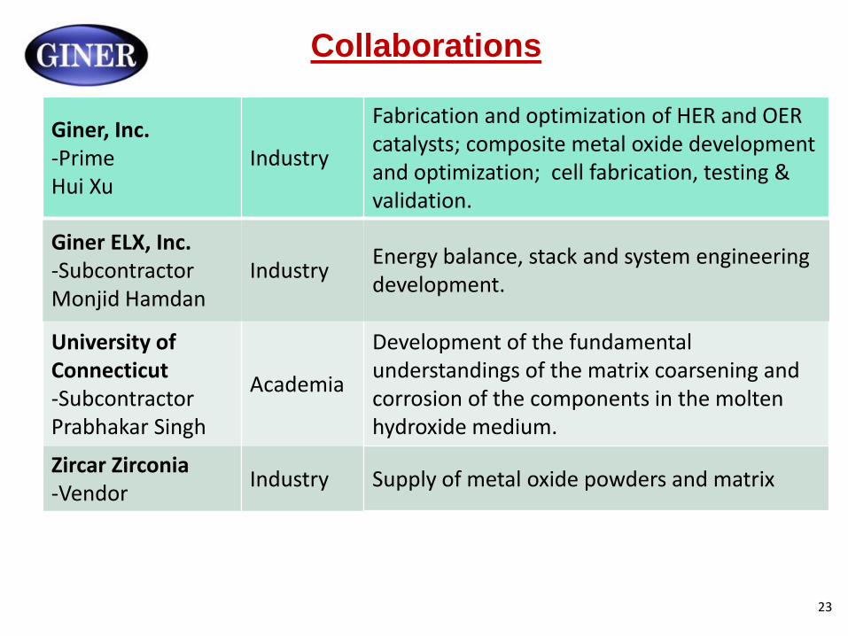
Collaborations
Giner, Inc. -Prime Hui Xu
Industry
Fabrication and optimization of HER and OER catalysts; composite metal oxide development and optimization; cell fabrication, testing & validation.
Giner ELX, Inc. -Subcontractor Monjid Hamdan
Industry Energy balance, stack and system engineering development.
University of Development of the fundamental Connecticut -Subcontractor
Academia understandings of the matrix coarsening and corrosion of the components in the molten
Prabhakar Singh hydroxide medium.
Zircar Zirconia -Vendor
Industry Supply of metal oxide powders and matrix
23
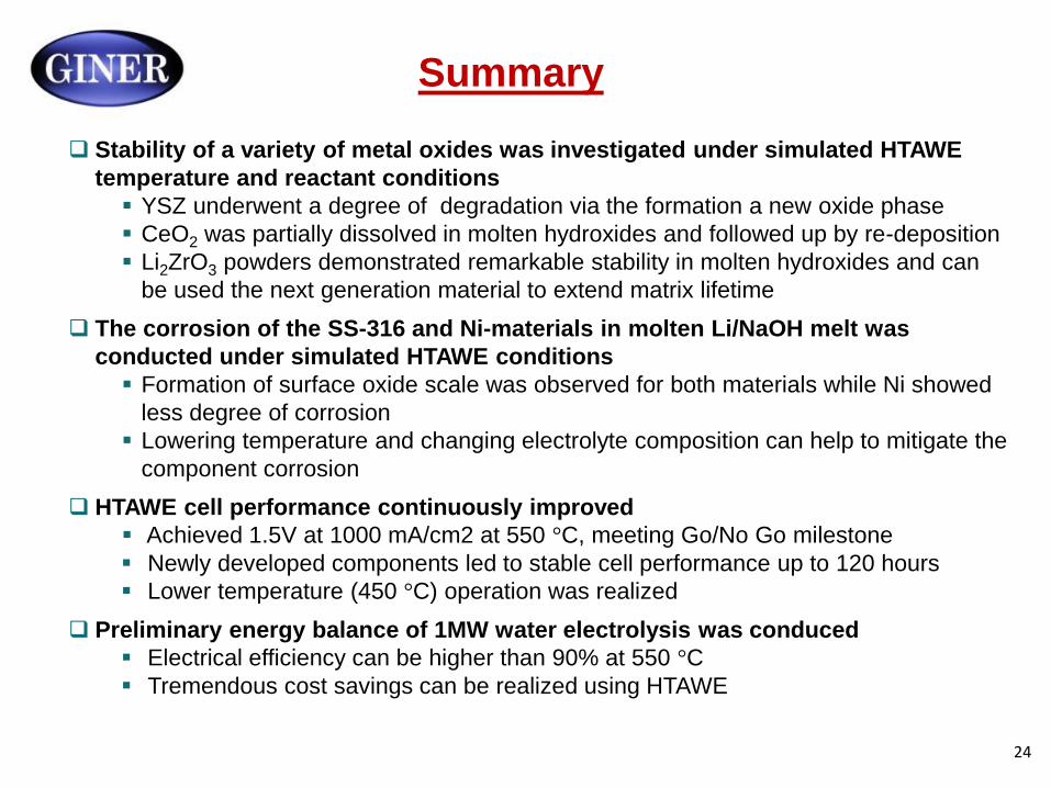
Summary
Stability of a variety of metal oxides was investigated under simulated HTAWE
temperature and reactant conditions
YSZ underwent a degree of degradation via the formation a new oxide phase
CeO2 was partially dissolved in molten hydroxides and followed up by re-deposition
Li2ZrO3 powders demonstrated remarkable stability in molten hydroxides and can
be used the next generation material to extend matrix lifetime
The corrosion of the SS-316 and Ni-materials in molten Li/NaOH melt was
conducted under simulated HTAWE conditions
Formation of surface oxide scale was observed for both materials while Ni showed
less degree of corrosion
Lowering temperature and changing electrolyte composition can help to mitigate the
component corrosion
HTAWE cell performance continuously improved
Achieved 1.5V at 1000 mA/cm2 at 550 °C, meeting Go/No Go milestone
Newly developed components led to stable cell performance up to 120 hours
Lower temperature (450 °C) operation was realized
Preliminary energy balance of 1MW water electrolysis was conduced
Electrical efficiency can be higher than 90% at 550 °C
Tremendous cost savings can be realized using HTAWE
24
Future Plans and Challenges (FY18-19)
Future Plans
Matrix and composite electrolyte optimizations
Synthesize new matrix material (e.g. Li2ZrO3-fine powder)
Optimize the Li2ZrO3-matrix fabrication process
Optimize electrolyte compositions-e.g. ternary electrolyte inventory
HER and OER catalysts optimizations at 450 °C
Fabricate thinner electrodes
Optimize microstructure design
Reduced electrolyzer cell temperature to 450 °C
Perform durability test at 450 °C for 300 h
Components corrosion mitigation
Optimize SS-316 or 310 and Ni-based current collector
Perform perovskite oxides coating to minimize corrosion at lower T
Design the stack module
Cost analysis and system design (Giner-Elx)
Future Challenges
Maintaining the electrolyte in the single/stack cells for long term durability
Maintaining the seals of single/stack cells 25
Acknowledgments
Financial support from DOE EERE Fuel Cell
Technology Office under award # DE-EE0007644
DOE program manager: Dr. David Peterson
Giner Personnel
- Corky Mittelsteadt, Steve McCatty,
Fuel Cell Energy: Dr. Chao-yi Yuh
26