high temperature air-water heat pump split -...
TRANSCRIPT

Installation and maintenance manual
PAC HT SplitHigh temperature air-water heat pump split
PAC HT Split12-6 / 14-7 / 18-9

2
[ GENERAL RECOMMENDATIONS ]
Please read the following safety precautions very carefully before installing the unit.
n SAFETY DIRECTIONSFollow the safety rules in forces when you are working on your appliance.The installation, commissioning and maintenance of these units should be performed by qualified personnel having a good knowledge of standards and local regulations, as well as experience of this type of equipment.This appliance has not been designed for use by persons (including children) with reduced physical, sensorial or mental faculties or by persons without any experience or knowledge of heating systems, unless they act under the safety and supervision of a responsible person or have received prior training concerning the use of the appliance.Children should be supervised to ensure that they do not play with the appliance.The unit should be handled using lifting and handling equipment appropriate to the unit’s size and weight.Any wiring produced on site must comply with the corresponding national electrical regulations.Make sure that the power supply and its frequency are adapted to the required electric current of operation, taking into account specific conditions of the location and the current required for any other appliance connected to the same circuit.The unit must be EARTHED to avoid any risks caused by insulation defects.It is forbidden to start any work on the electrical components if water or high humidity is present on the installation site.
n WARNINGCutoff power supply before starting to work on the appliance.When making the hydraulic connections, ensure that no impurities are introduced into the pipe work.The manufacturer declines any responsibility and the warrantly becomes void if these instructions are not respected.If you meet a problem, please call the Technical Department of your area.If possible, assemble the compulsory or optional accessories before placing the appliance on its final location. (see instructions provided with each accessory).In order to become fully familiar with the appliance, we suggest to read also our Technical Instructions.The information contained in these Instructions are subject to modification without advance notice.
POWER SUPPLY MUST BE SWITCHED OFFBEFORE STARTING WORK IN THE ELECTRIC CONTROL BOX

3
n EQUIPEMENT SAFETY DATA
Safety Data R407C
Toxicity Low
In contact with skin
Liquid splashes or sprays may cause freeze burns. Unlikely to be hazardous by skin absorption. However, R407C may be slightly irritant and, if liquid, it has a strong degreasing effect. Flush contaminated skin areas with running water. If it comes into contact with fabrics, the liquid refrigerant will cause them to freeze and adhere to the skin. Carefully remove the contaminated clothing since it might adhere to the skin and cause freeze burns. Contact a doctor if the affected skin areas are reddened or irritated.
In contact with eyes
Vapours have no effect. Liquid splashes or sprays may cause freeze burns. In these cases rinse your eyes with running water or with a solution for eye lavages for at least 10 minutes. Immediately contact a doctor.
Ingestion
Very unlikely to occur. If this should be the case, it may cause freeze burns. Never induce vomiting. Keep the patient awake. Make him rinse his mouth with running water and make him drink about 1/4 of a litre. Immediately contact a doctor.
Inhalation
R407C: High concentration levels of its vapours in the air can produce an anaesthetic effect, including the loss of consciousness. Particularly severe exposures may cause heart arrhythmia and sometimes prove to be also fatal.At high concentrations there is a danger of asphyxia due to a reduced oxygen content in the atmosphere. In these cases take the patient to the open air, in a cool place and keep him at rest. Administer oxygen, if required. Apply artificial respiration if breathing has ceased or if it has become irregular. In case of heart failure immediately apply cardiac massage. Immediately contact a doctor.
Further Medical Advice
A symptomatic and supportive therapy is generally suitable. A heart sensitisation has been observed in some cases, as a result of exposures to particularly high concentrations. In the presence of catecholamines (such as for example adrenaline) in the blood flow, it has increased the irregularity of the cardiac rhythm and then caused the heart failure.
Long-term exposure
R407C: A lifetime study which has been conducted on the effects inhalation may have on rats at 50,000 ppm has shown the onset of benign tumours of the testicle. These remarks suggest that there is no danger for human beings if they are exposed to concentrations below the occupational limits or equal to them.
Occupational exposure limits
R407C: Recommended limits: 1,000 ppm v/v 8 hours TWA.
Stability R407C: Not specified.
Conditions to avoid Use in the presence of exposed flames, red heat surfaces and high humidity levels.
Hazardous reactions Possibility of violent reactions with sodium, potassium, barium and other alkaline substances. Incompatible materials: magnesium and all the alloys containing over 2% of magnesium.
Hazardous decomposition products R407 C: Halogen acids deriving from thermal decomposition and hydrolysis.
General precautions
Avoid the inhalation of high concentrations of vapours. The concentration in the atmosphere shall be kept at the minimum value and anyway below the occupational limits. Since vapours are heavier than air and they tend to stagnate and to build up in closed areas, any opening for ventilation shall be made at the lowest level.
Breathing protection In case of doubt about the actual concentration, wear breathing apparatus. It should be self-contained and approved by the bodies for safety protection.
Storage PreservationRefrigerant containers shall be stored in a cool place, away from fire risk, direct sunlight and all heat sources, such as radiators. The maximum temperature shall never exceed 45°C in the storage place.
Protection clothes Wear boots, safety gloves and glasses or masks for facial protection.
Behaviour in case of leaks or escapes
Never forget to wear protection clothes and breathing apparatus. Isolate the source of the leakage, provided that this operation may be performed in safety conditions. Any small quantity of refrigerant which may have escaped in its liquid state may evaporate provided that the room is well ventilated.In case of a large leakage, ventilate the room immediately. Stop the leakage with sand, earth or any suitable absorbing material. Prevent the liquid refrigerant from flowing into drains, sewers, foundations or absorbing wells since its vapours may create an asphyxiating atmosphere.
DisposalThe best procedure involves recovery and recycle. If this is not possible, the refrigerant shall be given to a plant which is well equipped to destroy and neutralise any acid and toxic by-product which may derive from its disposal.
Combustibility features R407C: Non flammable in the atmosphere.
Containers If they are exposed to the fire, they shall be constantly cooled down by water sprays. Containers may explode if they are overheated.
Behaviour in case of fire In case of fire wear protection clothes and self-contained breathing apparatus.

4
[ INSPECTION AND STORAGE ]
At the time of receiving the equipment carefully cross check all the elements against the shipping documents in order to ensure that all the crates and boxes have been received. Inspect all the units for any visible or hidden damage. In the event of shipping damage, write precise details of the damage on the shipper’s delivery note and send immediately a registered letter to the shipper within 48 hours, clearly stating the damage caused. Forward a copy of this letter to the manufacturer or his representative.Never store or transport the unit upside down. It must be stored indoors, completely protected from rain, snow etc. The unit must not be damaged by changes in the weather (high and low temperatures). Excessively high tempera-tures (above 60 °C) can harm certain plastic materials and cause permanent damage. Moreover, the performance of certain electrical or electronic components can be impaired.
[ WARRANTY ]
The units are delivered fully assembled and tested.Any modification to the units without the manufacturer’s prior approval, shall automatically render the warranty null and void.The following conditions must be respected in order to maintain the validity of the warranty:q Commissioning shall be performed by specialised technicians from technical services approved by the manu-
facturer.q Maintenance shall be performed by technicians trained for this purpose.q Only Original Equipment spare parts shall be used.q All the operations listed in the present manual shall be performed within the required time limits.
THE WARRANTY SHALL BE NULL AND VOID IN THE EVENT OF NON-COMPLIANCE WITH ANY OF THE ABOVE CONDITIONS.
[ CONTENTS OF PACKAGE ]
q Outdoor unit:n 1 heat pump PAC HT Split
(outdoor unit)n 1 documentation pouchn 4 anti-vibration pads
q Indoor unit:n 1 heat pump PAC HT Split
(indoor unit)n 1 documentation pouchn 1 water filter kitn 1 stop cock
[ PRODUCT PRESENTATION ]
This range of air/water PAC HT Split (High Temperature) appliances offers the special feature of producing hot water at 65° C at outdoor temperatures between 0° C and -20° C, while guaranteeing a high COP.Between 0°C and +42°C, the temperature of the hot water produced varies between 65°C and 55°C for the Hea-ting mode and is maintained at 60°C for the Domestic Hot Water (DHW) mode.Consequently, this PAC HT Split system is ideally suited to replace a traditional hot water boiler in producing DHW without alterations to the rest of the system.
This technology uses two-stage compressors connected to a patented refrigeration circuit.This technology ensures remarkably accurate “capacity supplied/heating needs” matching due to its ability to run each compressor independently. Depending on the demand for heating capacity and the operating temperature of heat emitters (i.e. radiators, etc.) the PAC HT Split regulator selects either the small or large compressor to operate on its own or in a two-stage mode.

5
[ ACCESSORIES ]
n Set of stop cocks with pressure tapn Set of 2 flexible pipes (length 1m)n Hydraulic connection kitn Sludge pot (decanting filter)n Domestic hot water tank (300l)n Domestic hot water plate exchanger kits for:
- wall-mounted electric tank (DHW outflow via the bottom) - floor-mounted electric tank (DHW outflow via the top)
n Directional valve to be linked to the: - domestic Hot Water function. - boiler substitution function - swimming pool function (with temperature probe kit)
n 140 litre buffer tankn Anti-vibration pads (Anti-vibration mountings)n 6kW in-line electric heatern Dual zone Under-floor / Radiator heating kit (modulating valve + electric control box + temperature probe)n Dual zone management kit for existing valve (electric control box + temperature probe)n Wired programmable ambience terminaln Wireless programmable ambience terminal } Accessory recommended for an optimal functioning
[ DIMENSIONS ]
q See Appendix
[ HANDLING ]
q Outdoor unitTake care to avoid any rough handling or impacts when unloading and moving the appliance. Only push or pull the appliance by its base. Place a safety wedge between the unit base and the fork lift truck to avoid damaging the unit’s structure and casing.The handles present on the appliance’s panels are intended for the removal/refitting of the latter and must not be used for handling the complete appliance (too heavy to be supported by the panels).
q Indoor unit
NEVER USE THE REFRIGERATING PIPES TO MOVE THE UNIT.
Wedge required along the entire length of the unit
Transit holes Ø30 mm

6
[ NET WEIGHT (kg) ]
[ TECHNICAL SPECIFICATIONS ]
n PHYSICAL CHARACTERISTICS
q Outdoor unit
12-6 14-7 18-9
REFRIGERANT
Type R407C
Factory charge for links between 0 and 20 metres g See name plate
Additional charge between 20 and 45 metres g/m See appendix
LINKING PIPES
links between 0 and 25 mSuction (gas) pipe inches 5/8
Liquid pipe inches 3/8
links between 0 and 45 mSuction (gas) pipe inches 3/4
Liquid pipe inches 1/2
FANS
FANS (x2) 206 W - 700 tr/mn - 6000 m³/h
ACOUSTIC PRESSURE
Acoustic pressure – outdoor unit dB(A) 65 65 65
This equipment contains fluorinated gas with greenhouse gas effects covered by the Kyoto agreement.
q Indoor unit
12-6 / 14-7 * 18-9
LINKING PIPES
Gas inches 5/8
Liquid inches 3/8
HYDRAULIC LINKS
Inlet water gas 1" Female / Rotating nut
Outlet water gas 1" Female / Rotating nut
WATER FLOW
Nominal l/h 1030 / 1230 1480
Minimum l/h 880 / 1050 1260
Maximum l/h 1170 / 1390 1670
ACOUSTIC PRESSURE
Acoustic pressure- indoor unit dB(A) 41 41 41
q Outdoor unit
12-6 14-7 18-9
184 209 213
q Indoor unit
12-6 / 14-7* 18-9
28 28 30
* Outdoor unit common to Indoor units 12-6 and 14-7

7
n ELECTRICAL CHARACTERISTICS
q Outdoor unit
12-6 14-7 18-9
Supply voltage 400V / 3 Ph / 50Hz
Start-up current draw with limiter A < 60
MAXIMUM CURRENT
Only outdoor unit A 12.2 13.2 15.2
Outdoor unit + indoor unit + accessories* A 15.5 16.5 18.5
Supply voltage 230V / 1 Ph / 50Hz
Start-up current draw with limiter A < 45
MAXIMUM CURRENT
Only outdoor unit A 25.7 27.2 /
Outdoor unit + indoor unit + accessories* A 29 30.5 /
* Depending on the installation configuration, the power supply to the Indoor unit can either be separate or routed via the Outdoor unit (single master unit circuit protection).
q Indoor unit
12-6 / 14-7 * 18-9
Supply voltage 230V / 1 Ph / 50Hz
MAXIMUM CURRENT
Only indoor unit A 1.8
Indoor unit + accessories A 3.3
n OPERATING LIMITSPAC HT Split appliances are equipped with a 2-stage output system with a ratio of 1:2.When heating needs are low and when the required outlet water temperature is below 55° C, only the first stage is used at reduced capacity until the temperature balance point is reached. In other cases, the PAC HT Split ope-rates at full capacity to supply heating needs until the chosen balance point is reached.The outlet water temperature is automatically adjusted to the water rule (heating curve) up to a maximum tempe-rature of 65° C.
Wat
er o
utle
t set
poi
nt te
mpe
ratu
re (°
C)
Outside temperature (°C)
10-20 -15 -10 -5 0 5 10 15 20 25
15
20
25
30
35
40
45
50
55
60
65
70
DOUBLE STAGE
SINGLE STAGE
Double stage - minimum water return
Single stage - maximum water outlet
Double stage - maximum water outlet

8
n THERMODYNAMIC DOMESTIC HOT WATER PRODUCTIONq Performances
PAC HT Split 12-6 PAC HT Split 14-7 PAC HT Split 18-9
Configuration Compressor C2
Compressor C1+C2
Compressor C2
Compressor C1+C2
Compressor C2
Compressor C1+C2
Outdoor temp. °C 40 7 0 -10 40 7 0 -10 40 7 0 -10
PAC max. outlet temp. °C 60 60 65 65 60 60 65 65 60 60 65 65
Average capacity kW 9 5.5 10.6 9.3 11 7.1 13.6 12 13.3 8.3 16 14.1
DHW temperature °C 56 58 58 58 54 57 56 57 53 56 55 56
Time [min] Initial temperature: 15°C min 97 163 85 98 72 124 63 73 60 103 52 61
Time [min] Initial temperature: 35°C min 49 87 45 53 35 65 32 38 28 53 26 31
Tank capacity: 300 litres
THE ABOVE PERFORMANCE FIGURES ARE STATED FOR A SYSTEM WITH THE DOMESTIC HOT WATER TANK ACCESSORY.
The tank is equipped with a 2.5kW back-up heating element for single or three phase connection. The performances obtained and stated in the above table are without back-up heating. For higher domestic hot water temperatures or for Legionnaires disease protection treatment, the use of the back-up electric heating resistances is required.
q Pressure loss
[ REFRIGERATION AND HYDRAULIC DIAGRAM ]
q See Appendix
0
0.5
1
1.5
2
2.5
800 900 1000 1100 1200 1300 1400 1500 1600 1700 1800
kPa
Pres
sure
loss
Water flow (l/h) Pres
sure
loss
Water flow (l/h)
kPa
0
0.05
0.10
0.15
0.20
0.25
0.30
0.35
0.40
0.45
800 900 1000 1100 1200 1300 1400 1500 1600 1700 1800
DHW TANK 300 litres
3-WAY-VALVE HEATING/DHW

9
[ INSTALLATION ]
The unit is not designed to withstand weights or stresses from adjacent equipment, pipe work or construc-tions. Any foreign weight or stress on the unit structure could lead to a malfunction or a collapse with dangerous consequences for personnel and property. In such an event, the warranty shall be null and void.
OUTDOOR UNIT
n SITING THE INSTALLATIONThe outdoor unit must be installed outdoors with sufficient surrounding clearance to enable unobstructed air cir-culation through the appliance and access for maintenance work.
q Prevailing windIn the case of the unit being sited in areas exposed to high winds, you must avoid the wind hitting the fan blowing surface areas directly to avoid any risk of recycling cooled air. Exchanger fan operation can be disrupted by strong winds, which can cause de-icing problems and fan malfunctions.Unit operation depends on air temperature. Any recycling of air extracted by the fan lowers the air intake temperature across the exchanger fins and alters the standard operating conditions.The arrows show the direction of air circulation through the appliance. (Refer to the § ATTACHEMENT TO THE GROUND).
q Condensate water managementDepending on temperature and outdoor air humidity conditions, water vapour contained in the air can condense on the finned heat exchanger and even form ice under low outdoor temperature conditions (around < 5°C). This condensate water and defrosted water runs off via outlets provided under the exchanger. To aid water run-off and avoid frozen water remaining in the appliance in winter, we recommend that it is mounted at a height of around 10cm off the ground by installing the ant-vibration mounting kit. In this way, condensate and defrosted water can run off freely and be absorbed into the ground or channelled to a basin built under the appliance in order to protect the environment.In areas where outdoor temperatures fall below 1°C, the system can be equipped with a condensate anti-freeze protection system (e.g. a heated pipe sheath, Not supplied).
q How to reduce noise pollutionIn order to contain noise levels, we equip our appliances with quiet fans and encase the technical compartment in sound-proofed panels. However, noise levels can be reduced even further by following a few installation pre-cautions:
- Do not install the appliance near a bedroom window. Avoid locating the appliance in a corner (increased reverberated noise).
- Install the rubber pads supplied or anti-vibration pads (available as an option) under the appliance.- Do not join the concrete slab supporting the appliance to the structure of the dwelling (structure- borne noise
transmission).
n CLEARANCEWhen choosing the location for the appliance, take care to leave sufficient free clearance on all sides to ensure easy access for maintenance work. The minimum free clearance dimensions indicated must be observed to ensure both proper system operation and allow access for maintenance and cleaning.
REF. DIMENSIONA 800 mmB 500 mmC 500 mmD 400 mmE 800 mmF 100 mm
A
B
D
E
C
F
10
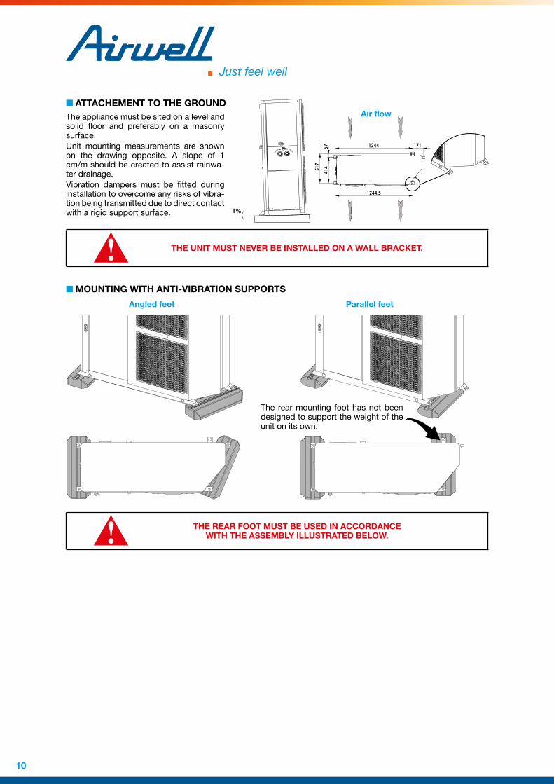
n ATTACHEMENT TO THE GROUNDThe appliance must be sited on a level and solid floor and preferably on a masonry surface.Unit mounting measurements are shown on the drawing opposite. A slope of 1 cm/m should be created to assist rainwa-ter drainage.Vibration dampers must be fitted during installation to overcome any risks of vibra-tion being transmitted due to direct contact with a rigid support surface.
THE UNIT MUST NEVER BE INSTALLED ON A WALL BRACKET.
n MOUNTING WITH ANTI-VIBRATION SUPPORTS
517
17112445741
4
1244.5
1%
Angled feet Parallel feet
The rear mounting foot has not been designed to support the weight of the unit on its own.
THE REAR FOOT MUST BE USED IN ACCORDANCE WITH THE ASSEMBLY ILLUSTRATED BELOW.
Air flow

11
NEVER USE THE REFRIGERATING PIPES TO MOVE THE UNIT.
A
D
C
B
260
INDOOR UNIT
n SITING THE INSTALLATIONThe unit has been designed for indoor applications and must be sited in a location protected from bad weather and without any risk of freezing during winter months. The premises must be clean, dry and properly ventilated.If there is a possibility of the indoor temperature falling below 1°C, you must take every precaution to provide anti-freeze protection for the hydraulic circuit (addition of mono-propylene glycol).When choosing the location for the appliance, take care to leave sufficient free clearance all around to ensure easy access for maintenance work. These minimum free clearance dimensions around the appliance should be main-tained in order to provide access to the unit.
n CLEARANCE
REF. DIMENSIONA 150 mmB 1160 mmC 100 mmD 100 mm
n WALL-MOUNTING1. Remove the Indoor unit casing.2. Attach the wall support (2 X Ø8 screws)3. Hang the Indoor unit.
➊
➋
➌

12
[ HYDRAULIC LINKS ]
When choosing and installing water pipes, you must consult and observe all current local standards, regulations and instructions.
n GENERAL RECOMMENDATIONSYou must design the pipe network with the minimum number of bends and keep the number of changes in height to the strict minimum. This will reduce installation costs and ensure optimum system performance. The pipe network must include:q A vibration elimination system (e.g.: link hoses available as an accessory) on all pipes connected to the appliance
in order to reduce vibrations and noise transmitted to the building fabric.q Stop cocks to isolate the hydraulic circuit during maintenance.q Manual or automatic bleed valves at the highest point on the water circuit.q A suitable system for maintaining water pressure in the circuit (expansion tank).q The installation of thermometers and pressure gauges on the heat exchanger inlet and outlet to facilitate day-
to-day controls and system maintenance.
n ANTI-CLOGGING PROTECTIONTo avoid any risk of foreign bodies entering the appliance and to guarantee operating performance, WE STRONGLY RECOMMEND THAT YOU INSTALL THE WATER FILTER ACCESSORY on the indoor unit inlet pipe.
When installing PAC HT Split appliances in existing water circuits, a sludge trap and a removable mesh filter should be installed upstream of the appliance.
n MINIMUM HEATED WATER VOLUME REQUIREMENTS – BUFFER TANK.To ensure that the system operates correctly you must use suitably sized and properly routed pipes for the hydrau-lic links between the Heat pump and the mains network.The volume of water contained in the installation must be sufficient to avoid any possibility of the compressor “short cycling”, and to guarantee adequate compressor running times in order to provide optimum service life and to ensure that de-icing cycles are performed properly.To ensure the PAC HT Split functions efficiently, available installation water volume must be:
200L < AVAILABLE WATER VOLUME < 250L
When water circulation through heat emitters can be interrupted (thermostatic radiator valves closed) or the hea-ting supply halted, you must ensure that:q The heat pump maintains its nominal water flow,q The heat pump operates in a loop with a minimum available volume of 200 litres.
The use of a 3-speed circulation pump enables water flow through the appliance to be adapted to pressure losses in the system. (Pump supplied set on Max position).

13
n STANDARD CIRCUITS
q PAC HT Split only
Layout 1: Application without room by room regulation This layout is recommended when the PAC HT Split water flow is continuous and close to the nominal value (no thermostatic valves).The buffer tank (2) provides extra circulating water volume to maintain the minimum volume.
CAPTIONS
NO. NAME
1 Shut-off valve
2 Buffer tank
3 Water filter Pot
4 Sludge pot
5 Three-way domestic hot water valve
6 300-litre domestic hot water tank
7 Plumbing safety unit
8 Recirculator pump
9 Circulator pump
11 Flow adjustment valve
12 Expansion vessel
13 On-line heater (optional)
14 Bleeder
15 Safety valve
16 Backflow preventer
Cold water
Hot water
Heat pump communication
DHW recycling loop
* Components not supplied.** Always check that the capa-
city of the vessel is suitable for the installation. Mandatory accessory.
Layout 2: Application with room by room regulation This layout is recommended for heating installations with wide operating water flow variations (radiator thermostatic valves present in the system). We strongly recom-mend including the buffer tank (2) as it guarantees that the heating loop capacity is higher than the minimum volume when the maximum number of thermostatic valves are closed.The flow regulating valve (11) is used to balance the flow in heating mode and domestic hot water production mode to always ensure optimum PAC HT Split operation.
3
2
1
1 1
31
EC
EF
5
6
7
8
1 1
1514
13
1
12
1
1 1
1
2
1
1 1
31
5
6
7
8
94
14
13
15
11
1
12
1
1
1 1
16
1 1
EC
EF
3

14
Layout 3: Application with room by room regulation This layout is also recommended for heating installations with wide operating water flow variations (radiator thermostatic valves present in the system). Minimum system volume is guaranteed by a mixing tank (10). Take care when calculating the volume of water in the installation and only take account of 50% of the mixing tank’s volume.Example: For a useful volume of 100 litres the actual mixing tank volume will be 200 litres.The flow regulating valve (11) is used to balance the flow in heating mode and domestic hot water production mode to always ensure optimum PAC HT Split operation.
CAPTIONS
REP. DÉSIGNATION
1 Shut-off valve
3 Water filter Pot
4 Pressure release valve
5 Domestic Hot Water 3-way valve
6 300-litre domestic hot water tank
7 Plumbing safety unit
8 Recirculator pump
9 Circulator pump
10 140-litre mixing tank
11 Flow adjustment valve
12 Expansion vessel
13 Optional in line warmer (see top diagram)
14 Drain or boiler
15 Safety valve
16 Backflow preventer
17 Domestic hot water preparation kit
Cold water
Hot water
Heat pump communication
DHW recycling loop
* Components not supplied.** Always check that the capa-
city of the vessel is suitable for the installation. Mandatory accessory.
Layout 4: Domestic Hot Water (DHW) production by way of the plate exchanger kit for fitment on the existing DHW tank Example: for a wall-mounted tank (DHW outflow via the bottom)A different kit is required for a floor-mounted tank (DHW outflow via the top). Please refer to the corresponding documentation.
3
1
31
5
6
10
7
8
9
4
14
17
13
15
11
1
12
1
1
1 1
1
111 1 1
EC
EF
1 1
16
16
3
1
1 1
31
5
6
10
7
8
9
4
14
13
15
11
1
12
1
1
1
1 1
16
11 1
EC
EF

15
q PAC HT Split as a boiler substituteWe recommend the fitting of a zone valve to avoid heat losses via the boiler when the PAC HT Split is working on its own. All system devices should be of a suitable size to limit pressure losses. Water flow within the heating circuit is normally driven by the circulation pump already present in the installation (recommended solution) or by the PAC HT Split’s circulation pump. In this case, you must ensure that the circulation pump generates sufficient water pressure.There is no need to replace the existing buffer tank on the circuit to take account of the small volume of water added by the presence of the PAC HT Split.IMPORTANT: the hydraulic kit available as an option enables you to prepare the circuit for connection to the PAC HT Split in accordance with our recommendations. The hydraulic kit is available with or without zone valves.
CAPTIONS
NO. NAME
1 Shut-off valve
3 Water filter Pot
4 Pressure release valve
5 Three-way domestic hot water valve
6 300-litre domestic hot water tank
7 Plumbing safety unit
8 Recirculator pump
9a/9b Circulator pump
10 140-litre mixing tank
11 Flow adjustment valve
12 Expansion vessel
13 Three-way domestic hot water valve
14 Boiler
15 Mixer valve
16 Backflow preventer
17 Dual-zone kit probe
18 Feeder
19 Safety valve
20 Mixing tank
21 Controller
Cold water
Hot water
Heat pump communication
DHW recycling loop
* Components not supplied.** Always check that the capa-
city of the vessel is suitable for the installation. Mandatory accessory.
q PAC HT Split dual zone installation (under-floor heating + radiators)The PAC HT Split manages a radiator zone (high temperature, zone 2) and an under-floor heating zone (low temperature, zone 1) by way of an under-floor temperature outlet probe, a modulating 3-way valve (230V 3 phase motor) and a water circulation pump for each zone. Each zone can be controlled by a dedicated ambience terminal, which then enables the PAC HT Split to manage 2 independent water laws. When the radiators zone is not in operation, the PAC HT Split switches over automatically to the under-floor heating water law, and thereby optimises the seasonal COP for the entire installation.
DO NOT FIT A BOILER SUBSTITUTE VALVE:• WALL-MOUNTED GAS-FIRED BOILER with domestic
hot water production and a single circulation pump used for both heating and domestic hot water.
• BOILER with a circulation pump.
3
1
1 1
31
5
6
10
7
8
9
14 134
11
1
12
1
1 1
16
EC
EF
1
1
1
1 1
3
1
1 1
31
5
6
10
7
8
14 13
189a
9b15 17
4
11
1
12
1
1 1
16
EC
EF
1 1
1 1
19

16
n WATER QUALITYThe water must be analyzed; the hydraulic network system installed must include all elements necessary for water treatment: filters, additives, intermediate exchangers, drain valves, vents, check valves, etc., according to the results of the analysis.
The PAC HT Split must not run on a network with open loops, likely to cause incidents related to oxygenation, or with non treated table water.
Using improperly treated or non treated water in the PAC HT Split may cause scaling, erosion, corrosion or algae or sludge deposits in the exchangers. Refer to a specialist skilled in water treatment to determine any treatment to apply. The manufacturer will not be held liable for damages caused when non treated or improperly treated water, demineralized water, salty water or sea water are used.
Apply the following guidelines:q No NH4+ ammonium ions in the water, highly detrimental to copper. <10mg/lq Cl- chloride ions are detrimental to copper with a risk of puncture by picking corrosion. <10mg/l.q SO42- sulphate ions may cause perforating corrosion. < 30mg/l.q No fluoride ions (<0.1 mg/l)q No Fe2+ and Fe3+ ions, particularly in case of dissolved oxygen. Fe< 5mg/l with dissolved oxygen < 5mg/l. The
presence of these ions with dissolved oxygen indicates corrosion of steel parts, likely to generate corrosion of copper parts under Fe deposits, particularly in the case of multitubular exchangers.
q Dissolved silica: silica is an acid element of water and may also cause corrosion. Content < 1mg/l.q Water hardness: TH > 2.8K. Values between 10 and 25 may be recommended. This facilitates scaling deposits
likely to limit copper corrosion. Excess TH values may lead to clogging the pipes.q TAC<100q Dissolved oxygen: Prevent any sudden change in the water’s oxygenation conditions. Also, avoid deoxygena-
ting water by sparging inert gas as well as overoxygenating it by pure oxygen sparging. Disturbing oxygenation conditions destabilizes copper hydroxides and particle salting-out.
q Electrical Resistivity - Conductivity: The higher the resistivity, the slower the corrosion. Values above 3000 ohm/cm are preferred. A neutral environment favours maximum resistivity. For electrical conductivity, values around 200-600 S/cm can be recommended.
q pH: neutral pH at 20°C (7 < pH < 8)
If the water circuit is to be drained for a time exceeding one month, the circuit must be fully charged with nitrogen to prevent any risk of corrosion by differential venting.
The manufacturer is not liable for recommendations in terms of water treatment (call a specialized company).However, this matter has a critical nature, and particular care must be given to ensure that the type of treatment applied is effective.
The liability of the manufacturer or its representative will not be sought when non treated water or non compliant quality water is used.
n CONNECTION TO THE CENTRAL HEATING LOOPYou must check water tightness and the cleanliness of the installation before connecting the PAC HT Split .For the PAC HT Split ’s WATER INLET and OUTLET connections, you must install manual stop cocks with the same diameter as the main pipe work. This will enable maintenance work to be carried out on the PAC HT Split without having to bleed the entire system. A link valve with pressure tap kit is available.The PAC HT Split must be protected by a water filter. When connecting this device to the PAC HT Split , take care to keep the water filter sieve pointing downwards. A sludge trap should be fitted in the event of high sludge build-ups.
An expansion tank adapted to the volume of water in the installation must be installed.
It is important to ensure that the mains water supply pressure is sufficient to fill the installation.
THE MANUFACTURER’S WARRANTY IS VOID IF THE FILTER SUPPLIED WITH THE PAC HT SPLIT IS NOT INSTALLED TO PROTECT THE APPLIANCE

17
WARNING!Take care not to damage the hydraulic pipe links by applying too much tightening pressure. Use a second wrench to compensate for the tightening torque.You should always use a counter-wrench for tightening valves.
n HEAT INSULATIONTo guarantee proper energy efficiency and compliance with current standards, water pipes passing through unin-habited zones should be properly lagged to retain heat.To achieve correct insulation with conductivity of 0.04 W/mK, lag the pipes with insulating material with a radial thickness between 25mm and 30 mm.
n FILLING THE SYSTEM WITH WATEROnce the installation is complete and after having clean and rinsed out the circuit network, you must fill the water circuit in accordance with current professional standards until you obtain the service pressure which will be:
0.5 bar < P. service < 2.5 bars.The PAC HT Split is equipped with an electronic water pressure sensor. This can be viewed on the main P1 screen on the display, as well as on the Maintenance screens.The water supply should come either from the mains network or from the Heat Pump or from any other point on the installation.Check that the automatic bleed valve operates correctly.You must completely bleed the circuit of all air to ensure efficient operation.Close the inlet water valve once the hydraulic circuit is filled correctly.
n SAFETY VALVE DRAIN CONNECTIONThe safety valve is equipped with a drain pipe. In the event of abnormally high heating circuit pressure (overheating, inadequate expansion tank water volume, faulty expansion tank, continuous filling…), water can be drained off via the valve. At the time of installation, you must ensure that these water discharges present no risk to the user. If necessary, connect the drain pipe to the waste water network via a siphon incorporating an opening to view proper water drainage.
n ELECTRONIC FLOW METERThe condenser water circuit is equipped with a vortex effect electronic flow meter. This device provides real-time readings of the installation’s water flow and reas-surance that this flow is adequate before starting the unit.The appliance is also equipped with a group of safety devices including a valve set at 3 bars, and a manual relief valve.
n WATER FLOW REGULATIONWater flow can be viewed on screen P2 as well as on the Maintenance screens.Use the water circulation pump speed selector to adjust the flow in the installation at the recommended nominal value (Refer to the § PHYSICAL CHARAC-TERISTICS). Pressure drop of the installation must be situated in the circulator operating range.

18
[ REFRIGERANT CONNECTIONS ]
n PIPE LINKS TO BE CREATED ON SITEThis work must be performed by qualified personnel in accordance with the best heating and air conditioning engineering practices (brazing, vacuum draining, filling, etc.).
1. Only use refrigeration quality copper pipe.2. Use anti-vibration collars for attaching pipe work to the
walls.3. To avoid the introduction of foreign bodies into the pipes
(dust, filings, etc.) always fit the pipes with end caps before handling or work.
4. Carefully unwind pipe coils in the opposite direction to the spirals and take care to avoid creating folds or twists.
q Refrigeration pipe bendingThe bending radius of the pipes should be equal to or more than 3,5 times de outside dia-meter of the pipe.Do not bend the pipes consecutively more than three times and do not make more than 12 bends over the complete length of the link.
q Link pipe lengthsPAC HT Split appliance is factory-charged with refrigerant for link pipe lengths of up to 20m. By observing the addi-tional charge chart (Refer to the § REFRIGERANT CONNECTIONS, appendix <?>) this length can be increased to 45m. PAC HT Split appliance can operate with a maximum height difference of 15m between modules.
q Pipe brazingPipes must only be cut with a pipe cutter (no filings) and then de-burred and scoured before brazing.You are advised to remove all grommets and protect the bodywork before starting any brazing work to avoid damaging the paintwork.To avoid introducing any scale deposits inside the pipes we recommend that brazing is performed in a dry nitrogen atmosphere by using the ¼" take-offs on the refrigerant stop cocks. One take-off is used to introduce the nitrogen and the other serves as a vent.The solder must contain at least 5% silver.
On the Indoor unit, we recommend that you braze the pipe links before making the electrical wiring connections.
1/4" STOP COCKTOP COCK CLOSED
VENT
LOW FLOW SUPPLY
DEHYDRATED NITROGEN
OUTDOOR UNIT
5% SILVER COLLAR
INDOOR UNIT

19
n PIPE INSULATION (NOT SUPPLIED)In order to avoid heat exchange with the ambient air, we recommend you insulate the pipe links between the Outdoor and Indoor units.The temperature in the gas pipe can exceed 100°C, while the liquid pipe temperatures are close to water inlet temperatures.Therefore, it is very important to insulate these pipes with quality lagging compliant with EN ISO 8497 standards (thermal conductivity λ<0.040 W/m.K). Furthermore, all pipe links should be protected by lagging of adequate thickness.In practice, we recommend an insulation thickness of 9mm for the liquid pipe and 13mm for the gas pipe (thermal conductivity λ<0.040 W/m.K).
Example on the gas pipe:q for a temperature difference between the fluid and the ambient air of 100K,q with 13mm thick insulation (thermal conductivity λ<0.040 W/m.K),q the heat loss is 18.7 W/m.
n VACUUM OF COOLING PIPES AND INDOOR UNIT
Only the outdoor unit is charged with refrigerant fluid. The indoor unit contains a small quan-tity of a neutral gas. This the reason it is imperative to vacuum the linking pipes and the indoor unit and always leave both the stop cocks on the outdoor modules in the closed position.
You should use a set of pressure gauges or a manifold to carry out this operation.
1. Keep the Outdoor Unit ball valves closed.2. Connect the end hoses to the ¼" take-off situated on the caged-ball valves (one hose on the liquid circuit stop
cock and one hose on the gas circuit stop cock). Connect the vacuum pump to the main hose.3. Open all the valves on the set of pressure gauges. Start the vacuum pump and check that the indicator needle
drops to – 0.2 mm Hg. Then leave the pump to run for at least 15 minutes.4. Before removing the vacuum pump, you must check that the vacuum indicator remains stable for at least five
minutes.5. Isolate the pump by closing the valves on the set of pressure gauges. Then stop the vacuum pump.6. Open the 2 caged-ball valves.7. In the case where one of the refrigeration links is 20m higher than the other, you must an additional refrigerant
fluid charge (Refer to the § REFRIGERANT CONNECTIONS, appendix <?>).8. To guarantee the tightness of the caged-ball valves, remember to refit the caps once the work is completed.9. Check tightness of the pipe links. Use an electronic leak detector or a soapy sponge.

20
[ WIRING DIAGRAM AND LEGEND ]
n WIRING DIAGRAMq See Appendix
n LEGEND
N 791
SE 4162 indoor unit 12-6/14-7/18-9 Control 1-Phase 230V +/-10% 50Hz
SE 4163 outdoor unit 12-6 Power 1-Phase 230V +/-10% 50Hz
SE 4164 outdoor unit 12-6 Control 1-Phase 230V +/-10% 50Hz
SE 4165 outdoor unit 14-7 Power 1-Phase 230V +/-10% 50Hz
SE 4166 outdoor unit 14-7 Control 1-Phase 230V +/-10% 50Hz
SE 4167 outdoor unit 12-6/14-7 Power 3-Phases 3N~400V +/-10% 50Hz
SE 4168 outdoor unit 12-6 Control 3-Phases 3N~400V +/-10% 50Hz
SE 4169 outdoor unit 14-7 Control 3-Phases 3N~400V +/-10% 50Hz
SE 4170 outdoor unit 18-9 Power 3-Phases 3N~400V +/-10% 50Hz
SE 4171 outdoor unit 18-9 Control 3-Phases 3N~400V +/-10% 50Hz
q Power supplyTerminal connections:
OUTDOOR UNITINDOOR UNIT
230 V +/-10% 50 Hz 3N~400V +/-10% 50 Hz
L: phase L1 (L1): phase
Connection to the FFG fuse holder and the earth terminal
N: neutral L2 (L2): phase
: ground L3 (L3): phase
N (N): neutral
: ground
The appliance’s electrical installation and wiring must comply with the country’s current standards.

21
q Wiring diagram key descriptions
OUTDOOR UNITFT1/2 M1/2 compressors thermo-magnetic relay (three phase models)FF1/2 M1/2 compressors protection fuse carrier (single phase models)KM1/2 M1/2 compressors power contactor or relayM1/2 Compressors
CM1/2 M1/2 compressors capacitors (single phase models)AS1/2 "Soft START" starterR1/2 Sump resistance
OF1/2 Air exchanger fan motorKOF1 OF1 fan motor relay
FOF1/2 OF1/2 motors internal safetyCOF1/2 OF1/2 motors capacitors
CF OF1/2 fan motor variatorFFC Control circuit protection fuse carrierKA1 Phase sequence and cut-out control module (three phase models)µPC Controller
FT1/2 Thermo-magnetic relays ancillary contacts for M1/2 compressorsHP Automatic reset high pressure switchEEV Electronic pressure relief valveIHP Intermediate high pressure switchDHP De-icing high pressure switchRV 4-way cycle changeover valves ISV Injection valveDRV De-icing valveESV Oil equalization valveEP Pressure transducer (evaporation pressure)
OCT De-icing temperature probe (evaporator inlet)CDT High discharge temperatureCST Evaporation temperature probe
INDOOR UNITFFG Main fuse holder FFT T1 transformer protection fuse (24V secondary circuit)T1 Ambience terminal 230/24V power supply transformer
WFL Flow meter (water flow measurement)WPR Water pressure sensorMP Water pump
KMP MP water pump relayEWT Inlet water temperature probeLWT Outlet water temperature probe
q Options
DZ WP/2 Dual zone water pumps
DZ MV Dual zone mixer valve
SP V Swimming pool 3-way valve
AEH1 Backup electric heating (Stage 1)
AEH2 Backup electric heating (Stage 2)
BOILER Hot water boiler (ON dry switch)
DHW WP Domestic Hot Water circulation pump (kit with plate exchanger)
DHW V Domestic Hot Water 3-way valve
DHW EH Domestic Hot Water tank electric heating resistance
BR V Substitute Boiler 3-way valve
DZWT Dual zone water temperature probe (Under-floor heating outlet)
DHWT Domestic hot water temperature probe
SPWT Swimming pool water temperature probe
ON/OFF Remote ON/OFF switch (Summer/Winter parameter settings)
DAY/NIGHT Off-peak hours electricity contact (DHW)
EMH Backup heating switch (electric heater and boiler substitution)

22
q Contactor fuse ratings, nominal currents settings (class AC3/AC1)
OUTDOOR UNIT
Supply voltages3N~400V +/-10% 50Hz
12-6 14-7 18-9
Only outdoor unit General protection fuse rating (not supplied) aM type (1) 16 A 16 A 20 A
Outdoor unit + indoor unit + accessories General protection fuse rating (not supplied) aM type (1) (2) 16 A 20 A 20 A
FUSE RATINGS
FFC aM type 4 A 4 A 4 A
THERMO-MAGNETIC CUT-OUT SWITCH
FT1Range 9 - 14 A 9 - 14 A 9 - 14 A
Setting 10 A 11 A 13 A
FT2Range 4 - 6.3 A 4 - 6.3 A 4 - 6.3 A
Setting 4.2 A 5.1 A 6.3 A
CONTACTORS
K1 12 A 12 A /
K2 9 A 9 A 9 A
Supply voltages230V +/-10% 50Hz
12-6 14-7
Only outdoor unit General protection fuse rating (not supplied) aM type (1) 32 A 32 A
Outdoor unit + indoor unit + accessories General protection fuse rating (not supplied) aM type (1) (2) 32 A 32 A
FUSE RATINGS
FF1 aM type 25 A 25 A
FF2 aM type 12 A 16 A
FFC aM type 4 A 4 A
CONTACTORS
K2 12 A /
(1) These values are provided for information purposes only and must be checked and adjusted in relation to currently applicable standards. They vary depending on the type of installation and the choice of conductors.(2) Depending on the installation configuration, the power supply to the Indoor unit can either be separate or routed via the Outdoor unit (single master unit circuit protection).
INDOOR UNIT
Supply voltages230V +/-10% 50Hz
12-6 / 14-7 18-9
FUSE RATINGS
FFG gG type 4A
FFT T type 1.6A
This 4A (gG) protection fuse corresponds to the appliance’s own consumption, plus the consumption of the various accessories available. Change the fuse rating if the consumption exceeds 4A (installation of additional pumps for example).

23
[ ELECTRICAL CONNECTIONS ]
WARNING
Before carrying out any work on the equipment, make sure that the electrical power supply is disconnected and that there is no possibility of the unit being started inadvertently.
Non-compliance with the above instructions can lead to injury or death by electrocution.
The electrical installation must be performed by a fully qualified electrician, and in accordance with local electrical standards and the wiring diagram corresponding to the unit model.Any modification performed without our prior authorisation may result in the unit’s warranty being declared null and void.The power supply cable section must be sufficient to provide the appropriate voltage to the unit’s power supply terminals, both at start-up and under full load operating conditions.The use of under-sized power supply cables can lead to major losses of around 100W to 200W.The power supply cable shall be selected in accordance with the following criteria:
1. Power supply cable length.2. Maximum unit starting current draw – the cables shall supply the appropriate voltage to the unit terminals
for starting.3. Power supply cables’ installation mode.4. Cables’ capacity to transport the total system current draw.
Short circuit protection shall be provided. This protection shall comprise fuses or circuit breakers with high brea-king capacity, mounted on the distribution board.If the planned installation includes an ambience terminal, the latter must be connected with shielded cable which must not run through the same conduits as the power supply cables, as the possible voltage generated could cause a unit operating fault.
n PHASE SEQUENCE AND CUT-OUT CONTROLLERq Very important:
3N~400V-50HzThe outdoor unit is equipped as standard with a phase sequence and cut-out controller located in the electrical box.
THE LED’S INDICATE THE FOLLOWING CONDITIONS:Green LED = 1 Green LED = 1 Green LED = 0Yellow LED = 1 Yellow LED = 0 Yellow LED = 0
Power ON Phase inversion or phase absent (L1) Phase absent (L2 or L3)The compressor rotation direction is
correct.The compressor and the fans do not
start.The compressor and the fans do not
start.
n PROGRESSIVE START-UP
3N~400V-50Hz
The PAC HT Split 18-9 is equipped with a progressive starter (soft start) for the C1 compressor. The starter is situated in the electrical box of the outdoor unit and marked “AS1”. It is important to check the following settings:q Start slope........................................................................... 1sq Stop slope ........................................................................... 0sq Minimum starting voltage ............................................... 60%
Start slope
Stop slope
Minimum starting voltage

24
230 V +/-10% 50 Hz
q Important :The compressors are equipped with a soft starter. The starter is situated in the electrical box of the outdoor unit and marked “AS1/2”.
THE LED’S INDICATE THE FOLLOWING CONDITIONS:
Green diode Red diode Meaning Recommended action Comments
On Off No fault
Off OffNo supply voltage present at starter
terminals.
Check the power supply to the PAC. Check the condition of the 230V protection
fuse. Replace the fuse if it has melted.
Flashing Off
Insufficient supply voltage (compressor
stopped).
Measure the compressor starter supply voltage at rest. Cut the power supply to
the PAC and check whether or not the fault reappears. Refer to the following cause in
the event of repeated failure.Defective starter power
supply component.Cut the power supply to the PAC. If the fault
persists, replace the starter.
On
Flashing twice Insufficient compressor
starting voltage (<190V).
Check the mains supply voltage at rest. Contact the electricity supplier if < 207V.
The alarm resets itself automatically after
5 min. If the fault re-occurs during the next start-up procedure, the
compressor seizes and the power supply has to be disconnected to reset it.
With the compressor running, check the mains supply voltage and the starter output voltage. In the event of major voltage drop,
check the diameter of the PAC power supply cable. As a last resort, contact the
electricity supplier.
On
Flashing 3 times Excessive compressor
starting current.
Force the compressor to start several times and check whether it is a one-off or
recurring fault.
The alarm resets itself automatically after
5 min. If the fault re-occurs during the next start-up procedure, the
compressor seizes and the power supply has to be disconnected to reset it.
If the fault persists, when the compressor is running, check for normal current draw. In the event of excessively-high current draw,
replace the compressor.Starter fault. Replace the starter.
On
Flashing 4 times Starter internal
condenser Replace the starter.
On
Flashing 5 times Incomplete or defective
compressor starting sequence
Force the compressor to start several times and check whether it is a one-off or
recurring fault.
The alarm resets itself automatically after 5 min. If the fault re-occurs during
the next start-up procedure, the compressor seizes and the power supply has to be
disconnected to reset it.
In the event of a persistent fault, check the compressor power supply cable.

25
n CONNECTIONSRemove the inspection cover to gain access to the electrical connection box.Pass the power supply cable through the cable passage provided on the appliance.Install end fittings suitable for the cable section to ensure a good contact. Make the connections as shown.
q Mains power supply
INDOOR UNIT
Mains power supply
OptionsMains power
supply
Com bus
OUTDOOR UNITA circuit breaker or fuse holder (not supplied) must be installed on the main power supply of the unit in accordance with the circuit diagram; for the ratings, refer to the electrical specifications.
NN L LNN L1 L1 L2 L3
Inspection cover
Mains power supply
Electrical cable passage
Mains power supply
Indoor unit bus
Indoor unit power supply *
3N~400v-50Hz 230V +/-10% 50Hz
Indoor unitMains power supply 400V
Indoor unit
Mains power supply 230V
* Depending on the installation configuration, the power supply to the Indoor unit can either be separate or routed via the Outdoor unit (single master unit circuit protection).

26
q Ambience terminal2 separate cables for power supply (24V) and communication (A-B-GND).Power supply 24V: Single pair cable 1 mm²Communication: Shielded twisted single pair cable with screen 0.33 mm² to 0. 5mm² (AWG 20/22)
A
B
24V AC/1
24V AC/2
GND
{{Communication
Power supply
{{ A
B
24V AC/1
24V AC/2
GND
Communication
Power supply
Raccordement du terminal d’ambiance
q Interconnection
D
C
GND
D
C
GND
Interconnection
Communication: Shielded twisted single pair cable with screen 0.33 mm² to 0.5 mm² (AWG 20/22)
Indoor unit Outdoor unit

27
[ DOMESTIC HOT WATER ]
n CONNECTION TO THE CENTRAL HEATING LOOPAn On-Off 3-way valve directs hot water produced by the PAC HT Split to either the heating circuit or the domestic hot water tank. Hydraulic connections must be made in accordance with the circuit layout diagrams provided.Warning: You must ensure that the 3-way valve orifices (marked A, B and AB) are connected correctly to the circuit in order for the valve to operate in accordance with the electrical diagram provided.
q 3-Way heating / domestic hot water valveFit the valve in accordance with the flow direction marks etched on the valve.
THE CONNECTIONS MUST CORRESPOND EXACTLY WITH THE FLOW DIRECTIONS INDICATED ON THE LAYOUT DIAGRAM FOR THE TYPE OF INSTALLATION.
Position the flow changeover control in the Y1 position.
A
B
AB
Motor disengagement
Domestic hot water tank
PAC HT SPLIT
Heating circuit
q Electrical connections
µPC
µPC µPC
DHW valve
DHW tank
DHW sensor
DHW valve DHW tank DHW sensor

28
PROG
Main screens P1 P4
Screen Reference
INSTALLATION MENU
ENTER
Power on screen
ESC
INSTALLATION MENU
MAIN MENU MP
ON/OFF-SUM/WIN O0
HEAT CURVE L1 L4
DOMESTIC HOT WATER ES0 ES10
ROOM TERMINAL TH0 TH3
ALARM LOG H1 H2
OPERATING TIME TM1 TM2
Screen Reference
Password
NEW PASSWORD
MANUAL OUPUTS
MANUAL DEICING
COMPRESSOR MNGT
MAINTENANCE
INSTALLATION CONFIG
DUAL ZONE
BOILER RELIEF
ELECTRIC HEATER
IE1 IE7DOMESTIC HOT WATER
WATER SETPOINT
WATER PUMP
MIENTER ENTER
ENTER
BOILER RELIEF R0 R1
n DOMESTIC HOT WATER PRODUCTION MODESThe PAC HT Split controller manages domestic hot water production in accordance with the following operating modes:
q Permanent comfort modeDomestic hot water production has priority over heating except when the ambiance temperature / set temperature difference is greater than 2° C (Maximum one hour).Example: Set temperature = 20°C, Ambience < 18°C
q Economy modeDomestic hot water is produced during off-peak hours (dry contact) or in accordance with times programmed in the controller.Option: Possibility to restart domestic hot water production outside off-peak hours if the water temperature has reached a programmable minimum temperature.
q Immediate domestic hot water productionThe PAC HT Split ’s regulator enables domestic hot water production to be forced as required. At the end of the cycle, the system returns to its usual operating mode.The Legionnaires’ Disease protection treatment managed by the PAC HT Split ’s controller is fully programmable (frequency, temperature threshold, treatment length).The PERMANENT COMFORT and ECONOMY modes place priority on thermodynamic heating. In the event of excessive demand for Domestic Hot Water Temperature that does not permit the compressor(s) to operate, the backup electric heating function is activated. In order to achieve energy savings, it is important to use the lowest possible set temperature points.
We recommend:ECO SET TEMPERATURE < COMFORT SET TEMPERATURE < 53°C
n DOMESTIC HOT WATER HEATING FUNCTION ACTIVATION

29
PROG
Main screens P1 P4
Screen Reference
INSTALLATION MENU
ENTER
Power on screen
ESC
INSTALLATION MENU
MAIN MENU MP
ON/OFF-SUM/WIN O0
HEAT CURVE L1 L4
DOMESTIC HOT WATER ES0 ES10
ROOM TERMINAL TH0 TH3
ALARM LOG H1 H2
OPERATING TIME TM1 TM2
Screen Reference
Password
NEW PASSWORD
MANUAL OUPUTS
MANUAL DEICING
COMPRESSOR MNGT
MAINTENANCE
INSTALLATION CONFIG
DUAL ZONE
BOILER RELIEF
ELECTRIC HEATER EH0 EH7
DOMESTIC HOT WATER
WATER SETPOINT
WATER PUMP
MIENTER ENTER
ENTER
BOILER RELIEF R0 R1
[ IN-LINE ELECTRIC HEATER ]
n ELECTRICAL CONNECTIONSq See Appendix
n OPERATING MODEOperating parameters for these modes can be set via the display on the PAC HT Split .
q Boost modeThe backup electric heating offers additional capacity when the demand for heating is higher than the capacity of the PAC HT Split. The aim is to maintain occupant comfort, while favouring thermodynamic operation for opti-mised performance.The resistances are only activated below a certain outdoor temperature (values can be set for Stage 1, AEH1 and Stage 1+2, AEH1+AEH2) and only if the PAC HT Split regulation system detects a lack of capacity in compressor only mode (check on water temperature and ambient temperature).Activation of the EMH Back-up switch on the heater switches the PAC HT Split into Back-up mode.
q Back-up modeAs opposed to Booster mode, this mode operates only when the user activates the EMH Back-up switch (this supposes an alarm on the PAC HT Split ). Outdoor temperature conditions are overridden and priority is no longer given to the thermodynamic mode but to the heating resistances that are nevertheless still controlled by the PAC HT Split.
n ELECTRIC HEATER FUNCTION ACTIVATION

30
PROG
Main screens P1 P4
Screen Reference
INSTALLATION MENU
ENTER
Power on screen
ESC
INSTALLATION MENU
MAIN MENU MP
ON/OFF-SUM/WIN O0
HEAT CURVE L1 L4
DOMESTIC HOT WATER ES0 ES10
ROOM TERMINAL TH0 TH3
ALARM LOG H1 H2
OPERATING TIME TM1 TM2
Screen Reference
Password
NEW PASSWORD
MANUAL OUPUTS
MANUAL DEICING
COMPRESSOR MNGT
MAINTENANCE
INSTALLATION CONFIG
DUAL ZONE
BOILER RELIEF IR0 IR4
ELECTRIC HEATER
DOMESTIC HOT WATER
WATER SETPOINT
WATER PUMP
MIENTER ENTER
ENTER
BOILER RELIEF R0 R1
[ BOILER RELIEF ]
n ELECTRICAL CONNECTIONSThe boiler relief function uses the digital outputs of the in-line electric heater function to control the hot water boiler ON/OFF switch (Boiler dry contact switch) as well as a 3-way valve output (230V BRV). A switch should be wired to the ICS input to ensure operation in Back-up mode.
n OPERATING MODESOperating parameters for these modes can be set via the display on the PAC HT Split.
q Boost modeHot water boiler operation is only authorised below a certain set outdoor temperature value and the appliance can also be placed in forced shutdown mode below a different outdoor temperature value. Just as the electric heater, the PAC HT Split continuously checks the water temperature and the ambient temperature to optimise compres-sor operation and to only start the hot water boiler when absolutely necessary.The PAC HT Split can also be set to manage a heat curve on the hot water boiler higher than the temperature set for the appliance (65° C maximum).
q Back-up modeActivation of the EMH switch (to be wired by the installer) or the Back-up parameter, via the “Boiler Relief” tab on the main menu of the PAC HT Split display, switches the system into Back-up mode and both outdoor tempera-ture and ambient temperature conditions are overridden.
We strongly recommend the installation of the ambience terminal for effective operation of the Boiler Relief function. In the absence of an ambience terminal the PAC HT Split will be unable to optimise hot water boiler operation and this will lead to unnecessary energy consumption.
n BOILER RELIEF FUNCTION ACTIVATION

31
PROG
Main screens P1 P4
Screen Reference
INSTALLATION MENU
ENTER
Power on screen
ESC
INSTALLATION MENU
MAIN MENU MP
ON/OFF-SUM/WIN O0
HEAT CURVE L1 L4
DOMESTIC HOT WATER ES0 ES10
ROOM TERMINAL TH0 TH3
ALARM LOG H1 H2
OPERATING TIME TM1 TM2
Screen Reference
Password
NEW PASSWORD
MANUAL OUPUTS
MANUAL DEICING
COMPRESSOR MNGT
MAINTENANCE
INSTALLATION CONFIG
DUAL ZONE DZ1 DZ8
BOILER RELIEF
ELECTRIC HEATER
DOMESTIC HOT WATER
WATER SETPOINT
WATER PUMP
MIENTER ENTER
ENTER
BOILER RELIEF R0 R1
[ DUAL ZONE ]
n ELECTRICAL CONNECTIONSq See Appendix
n ACTIVATING THE DUAL ZONE FUNCTION
You MUST install one room terminal per zone.
You must specify the type of emitter for each zone. Zone 1 corresponds to the low temperature zone. Setting the Aqu@Scop HT controls the water output tem-perature using the DZMV modulating valve and the DZWT temperature sensor.
n AMBIENCE TERMINALThe double zone function requires the use of one ambiance terminal per zone. You must specify one address per ambiance terminal.q Zone 1: Address 1q Zone 2: Address 2
CHANGING THE AMBIENCE TERMINAL ADDRESS FOR ZONE 2.See the communicating ambiance terminal’s installation manual (IOM WATTS 01-N-2ALL).

32
[ COMMISSIONING ]
n PRE-START CHECK LISTBefore commissioning the system, you must carry out a certain number of installation checks to ensure that the appliance will operate in the best possible conditions. The following list of checks is not exhaustive and only serves as a minimum reference guide.
q Visual check
1. Check free clearances around the unit, including the exchanger air intake and outlet, and access for maintenance work.
2. Comply with the free clearance dimensions around the domestic hot water tank.3. Check unit assembly in accordance with specifications.4. Check presence and tightness of all screws and bolts.5. Check the position of the rubber anti-vibration pads or the vibration-absorbing supports.6. Check that the unit is level and that condensates drain freely away from the unit.7. Check that there is no possibility of blown air being recycled through the fans due to wind exposure.8. In arduous climates (sub-zero temperature, snow, high humidity), check that the appliance is raised 10 cm
off ground.9. Check that the ambience terminal is located correctly (frequently occupied area, 1.5 m above ground level,
etc.).10. For refrigerant leaks in connections and components.
q Electrical check
11. Electrical installation has been carried out according to unit wiring diagram and the Supply Authority Regulations.
12. Size fuses or circuit breaker has been installed at the main power supply.13. Supply voltages as specified on unit wiring diagram.14. Check the tightness of wire to component connections.15. the cables and wires are clear of or protected from pipework and sharp edges.16. Check the electrical grounding of the appliance.
q Hydraulic check
1. Check that the external water circuit components (pumps, user equipment, filters, expansion tank and reservoir if supplied) have been correctly installed in accordance with the manufacturer’s recommendations and that the water inlet and outlet connections are correct.
2. Check the presence, direction and position of the water filter upstream of the appliance. Rinse the filter after the first 2 hours of operation.
3. Check that the water quality complies with stated standards.4. Check that the hydraulic circuit is filled correctly and that the fluid flows freely without any signs of leaks
or air bubbles.5. Adjust the water flow in order to comply with the specifications. (Refer to the § WATER FLOW REGULA-
TION, page 21)6. Check the presence and position of the stop cocks to isolate the appliance for maintenance.7. Check the presence of the air bleed valve.8. Check protection against freezing (heat isolation, antifreeze percentage if required...).9. Check that the bleed valve in the appliance has been opened.

33
[ STARTING THE APPLIANCE ]
After checking all the electrical connections and making any rectifications as required, proceed with starting up the installation.
n USER INTERFACEThe terminal is a 6-button, 8-line x 22-character LCD model, which can display text in various sizes and icons.
q Keypad
ALARM : When you press the Alarm key (the red bell is apparent if an alarm is active), the first active alarm is displayed on the screen and the screen buzzer is switched off (if active). Use the UP/DOWN keys to view all the active alarms. Press the Alarm key a second time to cancel all alarms that can be cancelled in this manner. Alarms that remain active are still displayed. If no alarm is active, pressing the key returns the system to the “NO ALARM ACTIVE” screen.
ESC : Moves to previous level in the menu arborescence. Press this to change an analogue or integer variable, such as 34.5 for example (as opposed to a digital variable such as Yes/No), to cancel the current change and return to the previous menu. This function is very important if a parameter is changed by mistake.
PROG : From any screen, this key returns to the main menu. Just as the ESCAPE key, this key cancels the current change.
UP/DOWN : These keys have several functions:In a menu, they enable you to scroll through the list of available selections. When the cursor is placed in the top left hand corner of the screen it is possible to scroll through the screens available in this arborescence.Finally, these keys enable you to change the value of a parameter when the cursor is placed on the parameter in question.
ENTER : On those screens where it is possible to change one or several parameters, the first press on the key moves the cursor to the first parameter on the screen. A second press validates the current parameter and the cursor scrolls to the following parameter until it returns to the upper left hand corner.
q Backlighting
All the screen keys are backlit.
The ALARM key diode lights up when at least one alarm is active. The key is lit when you are in the main menu or in one of its sub-menus.
The , , and keys light up along with the display backlighting.
If no key is pressed during a 5 minute period, the display automatically reverts to the first main screen (P1) and all backlighting is switched off.
Alarme
Prog
Escape
Up
Down
Enter

34
q Menus
The display comprises several menus. Some have unrestricted access and one (the Installation menu) is password protected.All the screens include a reference in the top right hand corner to make it easier to navigate between the different menus.
PROG
Main screens P1 P4
Screen Reference
INSTALLATION MENU
ENTER
Power on screen
ESC
INSTALLATION MENU
MAIN MENU MP
ON/OFF-SUM/WIN O0
HEAT CURVE L1 L4
DOMESTIC HOT WATER ES0 ES10
ROOM TERMINAL TH0 TH3
ALARM LOG H1 H2
OPERATING TIME TM1 TM2
Screen Reference
Password
NEW PASSWORD NI1
MANUAL OUPUTS S1 S6
MANUAL DEICING D1 D2
COMPRESSOR MNGT CP1
MAINTENANCE M1 M21
INSTALLATION CONFIG CI1 CI6
DUAL ZONE DZ1 DZ8
BOILER RELIEF IR0 IR4
ELECTRIC HEATER EH0 EH7
IE1 IE7DOMESTIC HOT WATER
CE1 CE2WATER SETPOINT
WATER PUMP C1 C5
MIENTER ENTER
ENTERBOILER RELIEF R0 R1
q Icons
P1
Outlet water set temperature, calculated from the heat curve parameters, the outdoor temperature, the ambience set temperature and the variance between the set and the ambience temperature.
Compressor 1 (large) in operation - Flashing => Compressor in time delay
Compressor 2 (small) in operation- Flashing => Compressor in time delay
Fan 1 (upper) in operation
Fan 2 (lower) in operation
Outlet water temperature
Inlet (return) water temperature
PAC HT Split in Summer mode
Flashing: Countdown for de-icing Fixed on: De-icing in progress
Circulation pump in operation
P3
Instantaneous outdoor temperature
ref. Reference outdoor temperature used by the PAC HT Split (upper fan special management)
Deice Evaporator inlet temperature (used for calculating the length of the de-icing time period).
Domestic hot water temperature (when the option is installed)
PAC HT Split in domestic hot water production mode (flashing)
Electric heater Stage 1 in operation (flashing)
Electric heater Stage 2 in operation (flashing)
Hot water boiler in operation (flashing)

35
n SIMPLIFIED START-UP PROCEDURE
q Main screensOn the PAC HT Split display, after having checked the coherence of the temperature probes on the main screens P1, P2 and P3, as well as effective communication with the ambience terminal, it is advisable to set the heat curve
parameters before starting the PAC HT Split. The main screen P1 is accessible by pressing the key several
times. The main screen P1 also appears after 5 minutes of display inactivity.
q Installation configuration
First of all, certain installation parameters must be configured via the “Config installation” menu.
PROG
Main screens P1 P4
Screen Reference
INSTALLATION MENU
ENTER
Power on screen
ESC
INSTALLATION MENU
MAIN MENU MP
ON/OFF-SUM/WIN O0
HEAT CURVE L1 L4
DOMESTIC HOT WATER ES0 ES10
ROOM TERMINAL TH0 TH3
ALARM LOG H1 H2
OPERATING TIME TM1 TM2
Screen Reference
Password
NEW PASSWORD
MANUAL OUPUTS
MANUAL DEICING
COMPRESSOR MNGT
MAINTENANCE
INSTALLATION CONFIG CI1 CI6
DUAL ZONE
BOILER RELIEF
ELECTRIC HEATER
DOMESTIC HOT WATER
WATER SETPOINT
WATER PUMP
MIENTER ENTER
ENTER
BOILER RELIEF R0 R1
CI1 Configuration of the type of heating emitter: radiators or under-floor heating. Changing this parameter auto-matically leads to changes in the water law parameters. It is very important to configure this parameter before making any alterations whatsoever to the water law parameters and before starting the PAC HT Split for the first time.

36
CI2 Outdoor temperature probe. This probe should not be installed remotely.
CI3 Ambience terminal Activation/deactivation (Default setting: activated). The temperature differential parameters in relation to the set ambient temperature control the starting and stopping of the PAC HT Split in terms of ambient temperature (even though the water law is also managed by ambient temperature conditions). As a default setting, the PAC will stop at the set ambient temperature + 1°C and restart at the set ambient temperature + 0.5°C (this enables the installation to anticipate any drop in ambient temperature and avoid excessive temperature fluctuations).
CI4 Configuration of the remote all or nothing ON/OFF input. Refer to the Indoor unit wiring diagram.
In ON/OFF configuration, this input enables the PAC HT Split to be stopped completely. When the boiler substitution function is activated, switching to OFF automatically activates the boiler. It is possible to configure this input as Normally Open or Closed (Default setting: NO).
In SUMMER/WINTER configuration, this input stops the Heating function while maintaining the DHW function active (equivalent to the ambience terminal switching to OFF). NO (Normally Open) or NC (Normally Closed) configuration is also possible.
CI5 Refer to the § TIME AND DATE VERIFICATION.
CI6 Display buzzer authorisation in the event of an alarm (Default setting: authorised).

37
RADIATOR HEAT CURVE PARAMETERS
20
25
30
35
40
45
50
55
60
65
70
-15 -10 -5 0 5 10 15 20
Outdoor temperature (°C)
Leavi
ng
wate
r te
mp
eratu
re s
etp
oin
t (°
C)
Correction Coef. 0,5
Correction Coef. 0,8
Correction Coef. 1,0
Base outd. T.
Base water SPT
Screen L1
Screen L2
Screen L3
Screen L4
q Heat curve parameters
On the main menu (key ), use the / arrows to highlight the “HEAT CURVE” menu. Validate this
selection with the key. This moves the display to the L1 screen. Use the and / keys to set the
following parameters:
Altitude: Installation site altitude, in km (e.g. 0.5km equals 500m. Default setting: 0).Base outd. T.: Typical outdoor temperature for the installation region (Default setting: -7°C).Corr. Coef.: Correction Coefficient for the base of the slope. This is a simple way of changing the water set temperature (Default setting: 0.8).
Losses at base Outdoor Temp : Estimated heat loss for the dwelling for an ambient temperature of 20°C and a base outdoor temperature (e.g. -7°C). This parameter is used to calculate the outdoor temperature that triggers the change from small compressor mode to two-stage compressor mode. This value is cap-ped at the maximum capacity of the PAC HT Split model in question for this same outdoor temperature (Default value = Maximum value).Water outlet temperature at -07°C Outdoor temperature : Outlet water tem-perature required at the base outdoor temperature (-7°C for example) to have an ambient temperature of 20°C (Default setting: 65°C).
Information screen for the outdoor temperature calculated automatically by the PAC HT Split . With the preceding default parameters, the value of 5.4° C means that below an outdoor temperature of 5.4° C the PAC HT Split will start the large compressor or the two-stage compressor. Above 5.4° C the PAC HT Split will start the small compressor.
The value of the outdoor balance temperature displayed on L4 is the one upda-ted by the PAC HT Split after running for some time, in the event that the PAC HT Split detects a lack of capacity with the small compressor.Zero reset: This is required in the event of changes to the heat curve parame-ters in order for the PAC HT Split to register these changes. The parameter on screen L3 is then recopied into screen L4.

38
PROG
Main screens P1 P4
Screen Reference
INSTALLATION MENU
ENTER
Power on screen
ESC
INSTALLATION MENU
MAIN MENU MP
ON/OFF-SUM/WIN O0
HEAT CURVE L1 L4
DOMESTIC HOT WATER ES0 ES10
ROOM TERMINAL TH0 TH3
ALARM LOG H1 H2
OPERATING TIME TM1 TM2
Screen Reference
Password
NEW PASSWORD
MANUAL OUPUTS S1 S6
MANUAL DEICING
COMPRESSOR MNGT
MAINTENANCE
INSTALLATION CONFIG
DUAL ZONE
BOILER RELIEF
ELECTRIC HEATER
DOMESTIC HOT WATER
WATER SETPOINT
WATER PUMP
MIENTER ENTER
ENTER
BOILER RELIEF R0 R1
Screen TH1
Screen TH0
q Verification of communication with the communicating ambience terminal
By default, the ambience terminal is declared in the regulator. This means that an alarm will be visible on the screen of the PAC HT Split a few seconds after the power supply is switched on, if the terminal is not connected. Proper terminal operation can be checked on screens TH1 to TH3.
All the terminal parameters are accessible via the “Ambience Terminal” menu in
the main menu (key ).
Screens: TH0 to TH3.
The screen TH0 appears when the terminal is deactivated (installation menu) or disconnected. This screen provides access to a set temperature to facilitate the inputting of water law offset values.
q Compressor sump heater function activationAfter the first power ON (compressors OFF), and for any outdoor air temperature, manually switch ON the com-pressor sump heaters.Before starting the compressors, the sump heaters must be powered On for at least 2 hours in order to evaporate any liquid refrigerant that could be in the compressors to ensure their lubrification at the first start-up.

39
Screen O0
Screen O0
q Indoor unit time and date verification
The time and the date are used to manage the:- alarm log.- the DHW Legionnaires Disease protection function.
When a communicating ambience terminal is connected to the PAC HT Split, the time is automatically updated in the regulator. The date is managed solely by the regulator. At commissioning, check:The date, screen P4. Update as required in the “Config installation” CI5 menu.The time (screen P4) if no ambient terminal is connected. Update as required in the “Config installation” CI5 menu.
q PAC HT SPLIT ON/OFF settingsIn order to start, the PAC HT Split must always be ON at the level of the appliance’s display. In addition, the ambience terminal must be in demand mode (when it is connected). To force the terminal to enter demand mode,
change it to Comfort mode with an ambience temperature set at 30° C.
The appliance OFF function will always have priority and therefore you will never be able to start the PAC HT Split in this mode.
From the main menu, use the / arrows to highlight the “ON/OFF-
SUMMER/WINTER” menu. Validate this selection by pressing the key.
The display moves to the O0 screen.
Press the key twice to move the cursor to the GENERAL OFF parameter.
Use the / arrows to change this parameter to ON.
Press to validate and then on the key .
If the ambience terminal is in demand mode, and if no alarm is active and the water temperature condition permits (inlet water at least 7° C below set temperature ), the PAC HT Split will start operating.Normal PAC HT Split operation is guaranteed with an appliance inlet (system return) water temperature above 20° C.

40
n OPERATING CHECK LIST
q GeneralCheek for any unusual noises or vibration in the running components, particularly the fan drive system.
q Phase rotation protectionIf the phase of the power supply are not correct, the phase rotation protection device will prevent the machine from starting.
q Electrical
OPERATING VOLTAGE Recheck voltage at unit supply terminals.
CONTROL Verify all sensor inputs, using the controller display.
q Fan & driveCheck that the fans rotate freely, in a balanced manner without any rubbing.
q Compressor and refrigeration system1. Checking operation: Start the PAC HT Split . Check for any abnormal noises
or vibrations.2. After a few minutes operation, the evaporator outlet superheating should be:
• 3K (±1K) with C2 compressor operating on its own, • 5K (±1K) with C1 + C2 compressors or C1 operating on its own. (*)
q Final check1. All panels and fan guards are in place and secured.2. Unit clean and free of remainder installation material.
[ FINAL TASKS ]
Place the plugs back on the valves and check that they are properly tightened.If needed, fix the cables and the pipes on the wall with clamping collars.Operate the PAC HT Split in the presence of the user and explain all functions.
[ IN CASE OF WARRANTY - MATERIAL RETURN PROCEDURE ]
Material must not be returned without permission of our After Sales Department.To return the material, contact your nearest sales office and ask for a “return form”. The return form shall be sent with the returned material and shall contain all necessary information concerning the problem encountered.The return of the part is not an order for replacement. Therefore, a purchase order must be entered through your nearest distributor or regional sales office. The order should include part name, part number, model number and serial number of the unit involved.Following our personal inspection of the returned part, and if it is determined that the failure is due to faulty material or workmanship, and in warranty, credit will be issued on customer’s purchase order. All parts shall be returned to our factory, transportation charges prepaid.
[ ORDERING SERVICE AND SPARE PARTS ORDER ]
The part number, the order confirmation and the unit serial number indicated on the name plate must be provided whenever service works or spare parts are ordered.For any spare part order, indicate the date of unit installation and date of failure. Use the part number provided by our service spare parts, if it not available, provide full description of the part required.
* These checks can be performed at the time of commissioning with the help of qualified technical personnel.

41
[ MAINTENANCE ]
The user is responsible for ensuring that the unit is in perfect working order and that the technical installation and minimum annual maintenance operations have been performed by a qualified technician in accordance with the procedures described in the present manual.
Some alarms can only be cancelled by switching the PAC HT Split to OFF.Generally, an alarm means that there is an anomaly present on the appliance. We strongly recom-mend that you refrain from repeatedly resetting an alarm without rectifying its cause in order to avoid the risk of causing irrevocable damage to one or several components.
Depending on actual operational constraints and regulatory changes, the installer might recommend increased maintenance operations and more frequent inspections.WARNING: Isolate unit from power supply before working on unit.
n SERVICING CHECKLISTCarry out a visual inspection of the complete installation in service.
q Outdoor unit1. Clean the outer panels.2. Remove the panels.3. Check that the insulation is not damaged. Repair as required.
q Condensate recovery tray1. Check that the drainage orifices are not blocked.2. Eliminate all accumulated dirt.3. Check that no traces of rust are present.
q Refrigeration circuit1. Check the absence of gas leaks.
A control of gas leaks absence should be performed on this device at least once a year, by a qualified technician. Referred to national requirements for the frequency of such controls.
2. Check that the copper tubes or the capillary tubes do not rub against any metal or vibrate.3. Check that the compressors do not generate any abnormal noises or vibrations.4. Check the compressor discharge temperature.5. Check that the crankcase heater is energised during the OFF cycle. (Switch on manually if necessary)
q Fin exchanger1. Clean the heat exchanger using a special product for aluminium-copper heat exchangers, and rinse with
water. Do not use hot water or steam, as this could cause the pressure of the refrigerant to rise.2. Check for signs of wear on the fan bearings.3. Verify the condition of the fans and the motors.
q Electrical equipmentLes interventions dans les boitiers électriques sont réalisées pars des techniciens habilités.
1. Check that the main power supply cable is not damaged or altered in such a way as to affect the insulation.2. Check that the interconnecting cables between the two units are not damaged or altered, and that they are
correctly connected.3. Check the tightness of the screw terminals.4. Check the general tightness of all cable connections.5. Perform a visual check of the condition of the contacts.6. Inspect the relay contact surfaces and the contractors and replace them if necessary.7. Check nominal current draw and the condition of the fuses.8. Clean the control box with compressed air to remove any build-ups of dust or dirt.9. Check the earth grounding connection.

42
q Protection devices1. Check the proper operation of the high pressure protection devices.
q Hydraulic circuit1. Check that the hydraulic circuit is filled correctly and that the fluid circulates freely without any sign of leaks
or air bubbles.2. Inspect filter cleanliness.3. Check water pressure and flow.
n INDOOR UNIT CLEANINGClean the aluminium panels with a micro-fibre cloth and water or a special aluminium cleaning product.
n OUTDOOR UNIT REFRIGERANT CHARGE RECOVERYIn the event of having to store the entire refrigerant charge contained in the Outdoor unit (in the case of work on pipe links between the Indoor and Outdoor units, moving the Outdoor unit…), the charge recovery procedure (pump down procedure) is available in the Maintenance menu. All the details and steps to follow are described on the various "RC" screens. Once the procedure has been completed, almost all the refrigerant charge will be stored in the Outdoor unit.
CAUTION
BEFORE CARRYING OUT ANY OPERATION ON THE EQUIPMENT, CHECK THAT THE ELECTRICAL POWER SUPPLY IS SWITCHED OFF
AND THAT IT CANNOT BE SWITCHED ON INADVERTENTLY.
IT IS RECOMMENDED THAT THE DISCONNECT SWITCH BE PADLOCKED

43
[ ALARM LIST AVAILABLE ON THE PAC HT SPLIT DISPLAY ]
Software version: 6.0Some terms may differ depending on the software version.
Ref. Alarm description
PAC HT Split action
Alarm cancellation
Time delay Possible cause(s) Recommended action(s)
AL01
Entering water temperature sensor disconnected or damaged
Complete shutdown Manual 10 s
Disconnected or faulty sensor Check the probe wiring, replace the probe if faulty.
AL02
Leaving water temperature sensor disconnected or damaged
Complete shutdown Manual 10 s
AL03
Outdoor temperature sensor disconnected or damaged
Complete shutdown Manual 10 s
AL04
Domestic hot water temperature sensor disconnected or damaged
DHW function stopped. Manual 10 s
AL05
Deicing temperature sensor (coil bend) disconnected or damaged
Thermodynamic function stopped
completely. Manual 10 s
AL06 Lack of water flow, freezing risk
Complete stoppage and forced water circulation pump operation during
stoppage
Manual
30s after start of
circulation pump
Seized water pump Check water pump operation
Clogged water filter. Clean the filter.
Water flow too low or air in the system
Check the PAC’s temperature difference in operation.
Increase the flow (change the water pump speed)
AL07
Double zone temperature sensor disconnected or damaged
Radiator zone stoppage, under-
floor heating water law, modulating
valve 100% open.
Manual 10 s Probe disconnected or faulty. Check the probe wiring, replace the probe if faulty.
AL08 Outdoor fans faultThermodynamic function stopped
completely. Manual None
Internal temperature protection cut-out in one of
the fans
Reset the alarm after allowing the motors to cool. Check which fan is overheating. Replace the defective fan.
AL09 Compressor 1 / big overload
Automatic changeover to C2
compressor WARNING: De-
icing impossible.
Manual (PAC HT Split OFF via
keypad)None Thermo-magnetic circuit
breaker tripped (three phase)
Reset the circuit breaker. Check that the setting
corresponds to specifications
AL10 Compressor 2 / small overload
Automatic changeover to C1
compressor
Manual (PAC HT Split OFF via
keypad)None Thermo-magnetic circuit
breaker tripped (three phase)
Reset the circuit breaker. Check that the setting
corresponds to specifications
AL11 High pressure lockout
Complete thermodynamic
function stoppage (no manual reset ).
Manual (PAC HT Split OFF via
keypad) after at least 2 minutes
stoppage
None
Refer to the fault diagnosis guide in the Installation and
Maintenance Manual
Refer to the fault diagnosis guide in the Installation and
Maintenance Manual
Water flow too low or air in the system
Re-establish nominal water flow or bleed the system
AL12 Low pressure lockout
Complete thermodynamic
function stoppage (no manual reset ).
Manual (PAC HT Split OFF via
keypad) after at least 2 minutes
stoppage
60 s after compressor
start-up
Refer to the fault diagnosis guide in the Installation and
Maintenance Manual
Refer to the fault diagnosis guide in the Installation and
Maintenance Manual
Coil blocked Clean the finned coil
ncomplete de-icing (lack of refrigerant charge)
Check the amount of refrigerant charge
AL13 Internal clock of the controller faulty. Information Manual None Defective internal regulator
clock.
Confirm the problem by switching the mains power on
several times. Replace the Indoor unit
regulator.
AL14 Both compressor alarm, unit stopped
Complete thermodynamic
function stoppage
Manual (PAC HT Split OFF via
keypad)None Both compressors in Alarm
modeFind the cause of the alarm
for each compressor

44
Ref. Alarm description
PAC HT Split action
Alarm cancellation
Time delay Possible cause(s) Recommended action(s)
AL16
Comm. loss PAC HT Split / room terminal, heating forced.
Switchover to forced Heating
mode by changing the
adjustable ambient temperature
(Default setting: 20° C)
Manual
Variable depending
on the cause of
the problem (clean trip or trip due to electrical interference)
Ambiance terminal is not connected
Deactivate it via the PAC HT Split keypad
One of the communication cables is disconnected
Check the connections on the PAC HT Split and the terminal as well as the
polarities (A and B)
Too much interference on the communication bus
Use shielded cable as recommended
AL17 Phase inversion or one phase missing
Complete shutdown Manual None
Power supply fault detection by the phase controller (three
phase)
Two phases have been inverted or one phase is missing. Refer to the
Installation and Maintenance Manual
AL18Deicing required, compressor 1 / big not available
Complete shutdown
Auto. If outdoor conditions permit natural de-icing
None
There is a fault on the large C1 compressor at a time when it is required by the PAC HT Split for de-icing
Rectify the fault on the C1 compressor
AL20Deicing by evaporating pressure < 0.6bar
De-icing Automatic after 30 min. compressor
operation. DVariable
Outdoor temperature or De-icing probe defective but
undetected.
Check the values recorded by the Outdoor and De-icing temperature probes. Replace
the probe if necessary.
Evaporation pressure sensor defective but undetected.
Check the evaporation pressure value in operation.
Replace the sensor if necessary.
Outdoor temperature too low for PAC HT Split operation.
AL21
2 deicings by evaporating pressure < 0.6bar in 30 minutes
Thermodynamic function stopped
completely.
Refrigerant leak. Checked for leaks. Check the refrigerant charge.
Ineffective de-icing, exchanger blocked. Clean the fin exchanger.
Outdoor temperature too low for PAC HT Split operation.
AL22Deicing ended abnormally by maximum duration
De-icing stopped
Auto. Alarm displayed for
10 minutes for information purposes
None
De-icing has lasted over 10 minutes. This is abnormal as de-icing usually takes between 3 and 4 minutes
Monitor the appliance to see if this fault is a one-off occurrence, If not, check
all possible causes of poor de-icing (lack of refrigerant
charge)
AL23
Deicing ended abnormally by leaving water temp. < 10°C
De-icing stopped
Auto. Alarm displayed for
10 minutes for information purposes
NoneOutlet water temperature during de-icing has fallen
below 10° C
Check that there is sufficient water volume in the system,
as recommended in the Installation and Maintenance
Manual
AL25Discharge temperature too high
Thermodynamic function stopped
completely. Manual None
Cut out by the N°2 compressor outlet temperature probe
Monitor to determine whether this fault is a one-off incident. If not, check the overheating
value on the display (may be too high in the event of
outflow being cut off).
AL27 Deicing valve failureThermodynamic function stopped
completely.
Manual (PAC HT Split OFF via
keypad)90 s
De-icing valve fault detected automatically by the control system. Valve disconnected,
inverted or blocked
Check valve wiring. Activate the Manual controller outputs
and check that the valve operates. Replace the valve if the slide is blocked or the coil
is burnt out
AL28Compressor 1 alarm by controller, 2 successive AL34
Automatic changeover to C2
compressorWARNING: De-
icing impossible.
Manual (PAC HT Split OFF via
keypad)90 s Fault detected
automatically by the system management (e.g. when the Temp. difference is
too low, indicating that the compressor has not started)
Refer to fault diagnosis guide in the Installation and
Maintenance Manual Probable cause: Faulty
single phase soft starter, compressor protection fuse
melted, excessively low supply voltage or phase
missing on the compressor. AL29
Compressor 2 alarm by controller, 2 successive AL35
Automatic changeover to C1
compressor
Manual (PAC HT Split OFF via
keypad)90 s
AL30Deicing problem - Compressor 1 or compressor valve
Automatic changeover to C2
compressor
Manual (PAC HT Split OFF via
keypad)90 s
Zero temperature difference during de-icing due to C1 compressor not starting or non activation of the
compressor changeover valve. Impossible to
determine the cause of the blockage in compressor C1
with certainty
Check that C1 is operating correctly.
Check the compressor changeover valve wiring.
Activate the Manual controller outputs and check that the valve operates. Replace the
valve if the slide is blocked or the coil is burnt out
AL31Compressor reversing valve failure
Automatic changeover to C2
compressor
Manual (PAC HT Split OFF via
keypad)10 s
Alarm generated by the intermediate pressostat. Compressor changeover
valve disconnected, blocked or coil burnt out
Check the compressor changeover valve wiring.
Activate the Manual controller outputs and check that the valve operates. Replace the
valve if the slide is blocked or the coil is burnt out

45
Ref. Alarm description
PAC HT Split action
Alarm cancellation
Time delay Possible cause(s) Recommended action(s)
AL32Entering/leaving water sensors reversed
Complete shutdown
Manual (PAC HT Split OFF via
keypad)90 s
Auto detection by checking whether the water
temperature probes are inverted.
Invert the probes at the level of the regulator. Check the probe values when the
compressor(s)is/are running.
AL33 DT > 20°C, low water flow
Complete thermodynamic
function stoppage
Manual (PAC HT Split OFF via
keypad)90 s
Insufficient water flow in the circuit, flow too low for proper PAC HT Split
operation
Check that the water flow in the system is always adequate (presence of
thermostatic radiator valves)Clean the inlet water filter on
the PAC HT Split
AL34Compressor 1 alarm by controller (water DT < 1°C)
Complete shutdown during 7 minutes. 2 cut-outs
AL28
Automatic 90 s Fault detected automatically by the system
management (e.g. when the Temp. difference is
too low, indicating that the compressor has not started)
Refer to fault diagnosis guide in the Installation and
Maintenance Manual Probable cause: Faulty
single phase soft starter, compressor protection fuse
melted, excessively low supply voltage or phase
missing on the compressor
AL35Compressor 2 alarm by controller (water DT < 1°C)
Complete shutdown during 7 minutes. 2 cut-outs
AL29
Automatic 90 s
INF36
--Information-- Back-up heater Boiler/Electric heater enabled
Information Stop backup mode None
Activation of the EMH digital input of the controller or
backup mode through the display for boiler relief
AL39Water pressure < 0.5bar in the heating circuit
Information Pressure > 1 bar for 5s. 10 s Insufficient water pressure in
the Heating circuit.
Add water to the heating circuit. Check proper
expansion tank operation. Check for leaks on the
Heating network.
AL40No communication with the outdoor unit
Complete thermodynamic
function stoppage
Manual and Com OK for 22s. 22s
Incorrect wiring. Check bus connections at both ends.
Communication bus cable cut.
Check the condition of the bus cable
Unshielded cable. Install shielded cable.
Outdoor unit not auto-detected.
Check the wiring of the Outdoor unit probes.
AL41
1 PAC HT Split unit not recognized on the communication bus
Information Automatic None
Probes B1 to B4, B8 and B9 partially or totally
disconnected on the unit in question.
Check the probe values on the display and check the
probe connections.
AL42
Indoor/outdoor units software versions incompatible
Complete thermodynamic
function stoppagePower supply cut. None Different versions for Indoor
and Outdoor units.Update the programme for
both units.
AL43No PAC HT Split model detected Split or Monobloc
Complete stoppage. Power supply cut. None
Probes B1 to B4, B8 and B9 partially or totally
disconnected on the unit in question.
Check the probe values on the display and check the
probe connections.
AL44PAC HT Split model modified for the indoor unit
Information None
Probes B1 to B4, B8 and B9 partially or totally
disconnected on the unit in question
=> incorrect model detection
Check the probe values on the display and check the
probe connections.
µPC replaced by that of another PAC HT Split (Split Indoor/Outdoor /Monobloc) Confirm once the situation is
understood.Programme taken from another PAC HT Split (Split Indoor/Outdoor/Monobloc)
AL45PAC HT Split model modified for the outdoor unit
Information None
Probes B1 to B4, B8 and B9 partially or totally
disconnected on the unit in question
=> incorrect model detection
Check the probe values on the display and check the
probe connections.
µPC replaced by that of another PAC HT Split (Split Indoor/Outdoor /Monobloc) Confirm once the situation is
understood.Programme taken from another PAC HT Split (Split Indoor/Outdoor/Monobloc).
AL46 Size modified for the outdoor unit Information None
Modification of the wiring of the analogue inputs B5
and B12 of the Outdoor unit configuration.
Check the status and the wiring of B5 and B12
Programme or µPC replaced by another Outdoor unit.
Confirm once the situation is understood.

46
Ref. Alarm description
PAC HT Split action
Alarm cancellation
Time delay Possible cause(s) Recommended action(s)
AL47 Different indoor and outdoor unit sizes Information None Different Indoor and Outdoor
unit sizes.
Check the sizes and their correspondence on the
makers plates. Check the status and the
wiring of inputs B5 and B12 on the Outdoor unit.
AL48Water flow meter disconnected or damaged
Complete stoppage. Manual 10 s
Flow meter disconnected or faulty.
Check the wiring of the flow meter, replace the flow meter
if it is faulty.
Faulty 0-5V supply. Measure the 0-5V voltage.
AL49
Water pressure sensor disconnected or damaged
Information Manual 10 ssWater pressure sensor
disconnected or damaged.
Check the sensor wiring, replace the sensor if it is
faulty.
Faulty 0-5V supply. Measure the 0-5V voltage.
AL50
Compressor discharge sensor disconnected or damaged
Complete thermodynamic
function stoppageManual 10 s Probe disconnected or
damaged.
Check the probe wiring, replace the probe if it is
faulty.
AL51
Evaporating temperature sensor disconnected or damaged
Complete thermodynamic
function stoppageManual 10 s Probe disconnected or
damaged.
Check the probe wiring, replace the probe if it is
faulty.
AL52
Evaporating pressure sensor disconnected or damaged
Complete thermodynamic
function stoppageManual 10 s Transducer disconnected or
damaged.
Check the transducer wiring, replace the transducer if it
is faulty.
INF56Software updated or new controller in the indoor unit
Information Manual None Programme update or µPC replaced in the Indoor unit.
Confirm once the situation is understood.
INF57Software updated or new controller in the outdoor unit
Information Manual None Programme update or µPC replaced in the Outdoor unit.
Confirm once the situation is understood.
INF58No indoor unit size in controller memory
Information Manual None Programme update or µPC replaced in the Indoor unit.
Check the size of the Indoor unit on the makers plate.
Key in the details and then confirm
AL59
Swimming pool sensor disconnected or damaged
Swimming pool function stopped. Manual 10 s Probe disconnected or
damaged.
Check the probe wiring, replace the probe if it is
faulty.
AL76
PAC HT Split stopped by outdoor temperature too high
Complete thermodynamic
function stoppageAutomatic None
Outdoor temperature too high (>40°C) for Heating or DHW
operation.
Wait until the outdoor temperature drops (restart value visible on the alarm
screen).
GENERAL COMMENTS:If you have a doubt about a PAC HT Split component, use the Manual activation function for the outputs (all the all or nothing outputs excluding the compressors) via the “INSTALLATION” menu on the appliances display. Use a voltmeter to check that the regulator output is activated (230V) and that the component is question in also acti-vated.The PAC HT Split retains a very comprehensive log of alarms, i.e. the 150 last alarms, as well as temperature probe values (water inlet and outlet, outdoor and outdoor battery) when the alarm appears. You can access this log from the main menu (sub-menu “Alarm log”).
Press the ENTER ( ) key to switch back and forth between the log screen and the probes screen.
Generally, an alarm means that there is an anomaly with the appliance. We strongly advise against repeatedly resetting an alarm at the risk of causing irreparable damage to one or several components.

47
[ FAULTY DIAGNOSIS GUIDE ]
Simple diagnosis advice. In the event of a breakdown, you should contact your local after sales department for confirmation and assistance.
Compressor does not start
Problem symptoms Probable cause Recommended action
Power is present at the compressor terminal but the motor does not rotate
Motor burnt out Replace the compressor
Motor contactor inoperable Coil burnt out or contacts broken Repair or replace the contactor
No current upstream of the motor contactor Circuit breaker tripped Check the fuses / thermo-magnetic circuit
breakers and electrical connections
Current upstream of the fuse, but not on the contactor side
Fuse blown or thermo-magnetic circuit breaker tripped
Replace the fuse. Reset the thermo-magnetic circuit breaker
Check current valuesLow voltage measured on voltmeter Voltage too low Contact your electricity supplier
No power supply to contactor coil Regulation open circuit
Use the appliance display to check that the system is actually calling for compressor
operationCompressor operates but current draw is abnormally high
Compressor damaged Replace the compressor
”Growling” compressor motorExcessive output pressure
Abnormally low voltage on start-up in single phase
Check the supply voltage. Refer to the single phase soft start faults chart
Check the controller control relays and their wiring (refer to wiring diagrams)
Compressor stops
Problem symptoms Probable cause Recommended action
HP pressostat triggered Excessively high outlet pressure Refer to instructions provided for “high outlet pressure”
Discharge thermostat triggered
Lack of refrigerant fluid Repair the leak. Add refrigerant fluid or completely replace the charge
Abnormal Compressor superheat Set the superheat on the expansion valve
Defective de-icing Check proper de-icing operation
Inlet pressure too low
Dryer filter blocked Replace dryer filter
Lack of refrigerant fluid Repair the leak. Add refrigerant fluid or completely replace the charge
Faulty expansion valve Replace the expansion valve
Abnormal icing up of finned exchanger Check proper operation of de-icing function
Dryer filter iced up Blocked dryer filter Replace the dryer filter
Compressor lubrication problem
Problem symptoms Probable cause Recommended action
Noisy compressor Fault in oil equalisation system Check operation of the oil equalisation valve. Contact your After Sales Service

48
Excessively high discharge pressure
Problem symptoms Probable cause Recommended action
Major difference between condensing and water outlet temperatures
Presence of incondensable matter in the system or excessive refrigerant fluid charge
Presence of air in water circuit
Bleed the incondensable matter and drain off the excess refrigerant fluid
Bleed the air from the circuit
High output pressure and very high water ∆T Insufficient water flow
Flow meter control Ensure that there is an adequate water flow
through the entire system
Excessively high inlet pressure
Problem symptoms Probable cause Recommended action
Presence of liquid in the intake line Expansion valve open too far
Check the overheating value on the display. Check the position of the pressure sensor and the evaporation temperature probe. Check the values present on the display.
Refrigerant fluid flow back towards the compressor, irrespective of the expansion valve setting
Expansion valve blocked in open position
Inspect the electronic regulator wiring on the Outdoor unit regulator.
Replace the regulator if it does not react when mains power is switched on to the unit.
Excessively low inlet pressure
Problems - symptoms Probable cause Recommended action
Excessive pressure loss across the dryer filter Clogged dryer filter Replace the dryer filter
Refrigerant does not pass through the electronic pressure relief valve, irrespective of the regulator settings.
The electronic pressure relief valve is faulty. Replace the electronic pressure relief valve.
The electronic pressure relief valve is disconnected from the Outdoor unit’s
regulator
Reconnect the electronic pressure relief valve wiring.
Loss of power
Expansion valve blocked Replace the expansion valve
Lack of refrigerant fluid Repair the leak. Add refrigerant fluid or completely replace the charge
Evaporator blocked Clean the finned evaporator
Insufficient air flow Check proper operation of the fan/motor units
Defective de-icing Check proper operation of de-icing function

49
Appendix

50
[ DIMENSIONS - OUTDOOR UNIT ]
1374
1308
10
1456.60
206 84
693
10
466
517
1711244
5741
4
1244.5

51
[ DIMENSIONS - INDOOR UNIT ]
2609
27
951084863
10057
720
52.5049.50
400
260
Ø3/8"
Ø5/8"
Ø 1"GasØ 1"Gas

52
[ REFRIGERATION AND HYDRAULIC LINKS DIAGRAM ]
1 Large compressor
2 Small compressor
3 Plate heat exchangers. Counter-current heating
4 Liquid tank
5 Plate heat exchangers. economiser
6 Finned heat exchanger and fans
7 Circulation pump
8 Oil separator
9 Dehydrator filter
10 Liquid warning light
11 Non-return valve
12 Automatic bleed
13 Flowmeter
V1 Four-way valve
V2 Four-way valve
V3 Injection electrovalve
V4 Electrovalve
V5 Injection expansion valve
V6 Electronic expansion valve
V7 Safety valve (3 bar)
P1 High Pressure safety pressostat
P2 High Pressure pressostat
P3 Defrost system high pressure control pressostat
P4 Evaporation pressure probe
P5 Water pressure probe
P Pressure take-off
CDT Outlet temperature probe
CST Evaporation temperature probe
LWT Water temperature probe (outlet)
EWT Water temperature probe (inlet)
OCT Outdoor coil temperature probe
OAT Outdoor air temperature probe
OUT
IN
12 7
V7
5
OFF
V1
OFF
V2
V3
V4
PP
8
8
V5
9
11
11
V6
10
OCT
OAT
6
EWT LWT
3
4
1
2CDT
CST
P5
P3
P2
P4
P1
P
P
13

53
L = 45 meters max.
L = 45 meters max.
H =
15
met
ers
max
.
L = 45 meters max.
H =
15
met
ers
max
.
Length(meter)
Ø gas line(inch)
Ø liquid line(inch)
Additionalcharge
(g)
20 5/8" 3/8" 0
21 5/8" 3/8" 57
22 5/8" 3/8" 114
23 5/8" 3/8" 171
24 5/8" 3/8" 228
25 5/8" 3/8" 285
26 3/4" 1/2" 1792
27 3/4" 1/2" 1904
28 3/4" 1/2" 2016
29 3/4" 1/2" 2128
30 3/4" 1/2" 2240
31 3/4" 1/2" 2352
32 3/4" 1/2" 2464
33 3/4" 1/2" 2576
34 3/4" 1/2" 2688
35 3/4" 1/2" 2800
36 3/4" 1/2" 2912
37 3/4" 1/2" 3024
38 3/4" 1/2" 3136
39 3/4" 1/2" 3248
40 3/4" 1/2" 3360
41 3/4" 1/2" 3472
42 3/4" 1/2" 3584
43 3/4" 1/2" 3696
44 3/4" 1/2" 3808
45 3/4" 1/2" 3920
[ REFRIGERANT PIPINGS AND ADDITIONAL CHARGES - PAC HT SPLIT ]

54
[ WATER FLOW CALCULATION GRAPH ]
0
10
20
30
40
50
60
70
80
0 500 1000 1500 2000 2500 3000 3500 4000
Water flow [l/h]
Ava
ilab
le p
ress
ure
[kP
a]
Max.flow
Min.flow
Nominalflow
Circulator operating range
0
10
20
30
40
50
60
70
80
0 500 1000 1500 2000 2500 3000 3500 4000
Water flow [l/h]
Ava
ilab
le p
ress
ure
[kP
a]
Max.flow
Min.flow
Nominalflow
Circulator operating range
0
10
20
30
40
50
60
70
80
0 500 1000 1500 2000 2500 3000 3500 4000Water flow [l/h]
Ava
ilab
le p
ress
ure
[kP
a]
Max.flow
Min.flow
Nominalflow
Circulator operating range
n PAC HT SPLIT 12-6
n PAC HT SPLIT 14-7
n PAC HT SPLIT 18-9
[ WIRING DIAGRAM ]
TAKE CARE!These wiring diagrams are correct at the time of publication. Manufacturing changes
can lead to modifications. Always refer to the diagram supplied with the product.
POWER SUPPLY MUST BE SWITCHED OFF BEFORE STARTING TO WORK IN THE ELECTRIC CONTROL BOXES!

55
n PAC HT SPLIT 12-6 230V +/-10% 50HZ
CO
NTR
OL
WIR
ING
DIA
GRA
M
SE 4
164
399
1224
PAC
HT
SPLI
T (1
2-6)
230
V
LEG
END
N
791
OU
TDO
OR
UN
IT
>>
µPC
>

56
POW
ER W
IRIN
G D
IAG
RAM
SE 4
163
3991
223
LEG
END
N
791
PAC
HT
SPLI
T (
12-6
) 23
0V
OU
TDO
OR
UN
IT

57
n PAC HT SPLIT 14-7 230V +/-10% 50HZ
CO
NTR
OL
WIR
ING
DIA
GRA
M
SE 4
166
399
1226
PAC
HT
SPLI
T (
14-7
) 23
0V
LEG
END
N
791
OU
TDO
OR
UN
IT
>>
µPC
>

58
POW
ER W
IRIN
G D
IAG
RAM
SE 4
165
3991
225
LEG
END
N
791
PAC
HT
SPLI
T (1
4-7)
230
V O
UTD
OO
R U
NIT

59
n PAC HT SPLIT 12-6 3N~400V +/-10% 50HZ
CO
NTR
OL
WIR
ING
DIA
GRA
M
SE 4
168
3991
228
LEG
END
N
791
PAC
HT
SPLI
T (1
2-6)
3N
400V
O
UTD
OO
R U
NIT
>>
µPC
>

60
n PAC HT SPLIT 14-7 3N~400V +/-10% 50HZ
CO
NTR
OL
WIR
ING
DIA
GRA
M
SE 4
169
3991
229
LEG
END
N
791
PAC
HT
SPLI
T (1
4-7)
3N
400V
O
UTD
OO
R U
NIT
>>
µPC
>

61
n PAC HT SPLIT 12-6 / 14-7 3N~400V +/-10% 50HZ
POW
ER W
IRIN
G D
IAG
RAM
SE 4
167
PAC
HT
SPLI
T (1
2-6+
14-7
) 3N
400V
399
1227
LEG
END
N
791
OU
TDO
OR
UN
IT

62
n PAC HT SPLIT 18-9 3N~400V +/-10% 50HZ
CO
NTR
OL
WIR
ING
DIA
GRA
M
OU
TDO
OR
UN
ITSE
417
139
9123
1
LEG
END
N
791
PAC
HT
SPLI
T (1
8-9)
3N
400V
>>
µPC
>

63
POW
ER W
IRIN
G D
IAG
RAM
SE 4
170
399
1230
LEG
END
N
791
PAC
HT
SPLI
T (1
8-9)
3N
400V
O
UTD
OO
R U
NIT

64
n PAC HT SPLIT INDOOR UNIT
WIR
ING
DIA
GRA
M
LEG
END
N
791
PAC
HT
SPLI
TIN
DO
OR
UN
IT
SE 4
162
A39
9122
2
µPC

65
[ DOMESTIC HOT WATER TANK ]
[ ELECTRIC HEATER + DUAL ZONE KIT ]
µPC PAC HT Split controllerDHW WT Domestic hot water tank
µPC PAC HT Split controllerAEH Additional electric heater
PAC HT SPLIT
DHW WT BALLON D'EAU CHAUDE SANITAIRE
DHW WT
DHW WT DOMESTIC HOT WATER TANK
DHW WT BRAUCHWASSERVERSORGUNG
DHW WT ACUMULADOR DE AGUA CALIENTE SANITARIA
DHW WT PALLA DI ACQUA CALDA SANITARIA
µPC
µPC REGULATEUR DE L'AQU@SCOP HT SPLIT
µPC AQU@SCOP HT SPLIT CONTROLLER
µPC KONTROLLEUR DES AQU@SCOP HT SPLIT
µPC CONTROLLO ELETTRONICO DEL AQU@SCOP HT SPLIT
µPC CONTROL DE LA AQU@SCOP HT SPLIT
PAC HT SPLITµPC
AEH CHAUFFAGE ELECTRIQUE ADDITIONNELµPC REGULATEUR DE L' AQU@SCOP HT SPLIT
AEH
AEH ADDITIONAL ELECTRIC HEATERµPC AQU@SCOP HT SPLIT CONTROLLER
AEH ZUSATZLICHE ELEKTROHEIZUNGµPC KONTROLLEUR DES AQU@SCOP HT SPLIT
AEH CALEFACCION ELECTRICA ADICIONALµPC CONTROL DE LA AQU@SCOP HT SPLIT
AEH RESISTENZE ELETTRICHE ADDIZIONALEµPC CONTROLLO ELETTRONICO DEL AQU@SCOP HT SPLIT

66
[ PERFORMANCES ]
n PAC HT SPLIT 12-6
Air 7°C Water 35°C
Air 2°C Water 35°C
Air -7°C Water 35°C
Air -15°C Water 35°C
Air 7°C Water 45°C
Air 7°C Water 55°C
Air -7°C Water 55°C
Air 20°C Water 55°C
Outdoor temperature 2 2 -7 -15 7 7 -7 20
Outlet water temperature 35 35 35 35 45 55 55 55
Water flow L/h 1 008 1 008 1 008 1 008 960 584 584 584
Heating capacity W 6 000 8 640 8 960 7 200 5 760 5 520 9 000 7 600
Power input (1) W 1 459 2 784 2 934 2 796 1 868 2 286 3 681 2 176
COP 4.11 3.10 3.05 2.57 3.08 2.42 2.45 3.49
Compressor C2 C1+C2 C1+C2 C1+C2 C2 C2 C1+C2 C2
n PAC HT SPLIT 14-7
Air 7°C Water 35°C
Air 2°C Water 35°C
Air -7°C Water 35°C
Air -15°C Water 35°C
Air 7°C Water 45°C
Air 7°C Water 55°C
Air -7°C Water 55°C
Air 20°C Water 55°C
Outdoor temperature 2 2 -7 -15 7 7 -7 20
Outlet water temperature 35 35 35 35 45 55 55 55
Water flow L/h 1 260 1 260 1 260 1 260 1 200 730 730 730
Heating capacity W 7 500 10 800 11 200 9 000 7 200 6 900 11 250 9 500
Power input (1) W 1 820 3 473 3 660 3 488 2 330 2 851 4 592 2 714
COP 4.12 3.11 3.06 2.58 3.09 2.42 2.45 3.50
Compressor C2 C1+C2 C1+C2 C1+C2 C2 C2 C1+C2 C2
n PAC HT SPLIT 18-9
Air 7°C Water 35°C
Air 2°C Water 35°C
Air -7°C Water 35°C
Air -15°C Water 35°C
Air 7°C Water 45°C
Air 7°C Water 55°C
Air -7°C Water 55°C
Air 20°C Water 55°C
Outdoor temperature 2 2 -7 -15 7 7 -7 20
Outlet water temperature 35 35 35 35 45 55 55 55
Water flow L/h 1 487 1 487 1 487 1 487 1 416 861 861 861
Heating capacity W 8 850 10 800 11 200 9 000 7 200 6 900 11 250 9 500
Power input (1) W 2 085 3 372 3 554 3 387 2 262 2 768 4 458 2 635
COP 4.24 3.20 3.15 2.66 3.18 2.49 2.52 3.61
Compressor C2 C1+C2 C1+C2 C1+C2 C2 C2 C1+C2 C2
(1) According to EHPA and EN 14511

67

3, AVENUE DU CENTRE, LES QUADRANTS, BAT. A - 78280 GUYANCOURT, FRANCE
TEL: +33 (0)1 76 21 82 00 FAX: +33 (0)1 76 21 82 01 www.airwell-residential.com
IOM
PA
C H
T sp
lit G
B 0
815
- S
pec
ifica
tions
sub
ject
to
chan
ge w
ithou
t no
tice.
Pic
ture
s no
n co
ntra
ctua
l. P
rinte
d in
UE
.