high strength solution-strengthened ferritic ductile cast iron
TRANSCRIPT
Rilwan Okunnu High Strength Solution-Strengthened Ferritic Ductile Cast Iron Master’s Thesis Espoo, August 10, 2015
Supervisor: Professor. Juhani Orkas Advisor: Kalle Jalava, M.Sc
“We do not grow absolutely, chronologically. We grow sometimes in one dimension, and not in another; unevenly. We grow partially. We are relative. We are mature in one realm, childish in another. The past, present, and future mingle and pull us backward, forward, or fix us in the present. We are made up of layers, cells, constellations.”
― Anaïs Nin
Aalto University, P.O. BOX 11000, 00076 AALTO www.aalto.fi
Abstract of master's thesis
Author: Rilwan Okunnu Title of thesis: High Strength Solution-Strengthened Ferritic Ductile Iron
Degree programme: Mechanical Engineering Major: Mechanical Engineering Code: IA3027
Thesis supervisor Professor. Juhani Orkas Thesis advisor(s): M.Sc. Kalle Jalava Date August 10, 2015 Number of pages: 80 Language English Abstract: High Silicon ductile iron (SSFs) represents a state-of-art in standardized ductile Iron grades, because it uniquely combines uniform hardness, intermediate strength and ductility rivalling that of some steels. Also backed by economic and technical potentials, it is imperative to take advantage of these unique properties to explore avenues to reach even higher strength levels in this grade. Within the SSF grade, strengthening limit with Silicon is reached at 4.3wt% with mechanical properties markedly plunging at this point, necessitating the need to investigate alternative strengthening measures aside expensive heat treatments, hence thesis objective to research methods to develop high strength SSF ductile irons as-cast. Casting process and production methods to mitigate against challenges of current SSF irons also form part of this objective. Researching and developing high strength SSF offers to the engineering materials pool, aside from obvious financial benefits, additional options in material selection for different applica-tions, energy savings due to lighter castings, improved tool life from uniform hardness and boost knowledge on suitability of cast irons as viable replacements for steel in some applica-tions. The solution approach in the thesis started with extensive literature reviews and background researches on DI standardized grades with emphasis on the SSFs and strengthening mecha-nisms to understand present challenges of these grades. The idea was then to aim for higher strength using the EN-GJS-600-10, the SSSF grade with the highest Silicon content and strength as both reference and base iron for designing the experimental high strength SSF. Using a suc-cession of elimination methods in the product development process based on identified pa-rameters for high strength in DIs, such as improving graphite properties, reducing carbidic pres-ence etc., controlled chemical composition with Cobalt (Co) as alloying element was proposed. The result of the casting trials proved that Co indeed fortified the experimental SSF showing increase in strength and elongation. Graphite properties were improved, with refined nodules and higher nodule counts. In addition, no apparent graphite degeneracy was noticed in the microstructure with a homogenous ferritic matrix. The overall qualities of the Co-alloyed irons were better compared to the reference EN-GJS-600-10. The significance of the results is that silicon limit in current SSF grade does not affect the possi-bility of reaching higher strength via controlled alloying with other element. Co alloying provid-ed better graphite attributes in the Iron which influenced elongation and cast quality. Although from the result data, it is statistically insufficient to ascertain if further increase in Co will be proportional to strength or elongation, Co however, similar in effect to Si, stabilizes austenite contributing positively to strength, increased nucleation and nodularisation efficiency. Keywords Ductile irons, Solution strengthened ferritic irons, solid solution, strengthen-ing mechanisms, casting, tensile testing, microscopy
Acknowledgment Firstly, I am grateful to Finland for creating this sustainable and top-notch educational
system which I have benefited from. It has been an enlightening journey for me and I
am highly appreciative of this.
I would like to thank Professor Juhani Orkas for giving me the opportunity to work on
this thesis, it has been one of the most enjoyable projects of my academics and I hope I
repaid the faith in letting me work on it.
My greatest gratitude however, goes to my thesis advisor, Kalle Jalava; I am extremely
indebted for your help throughout the thesis work. From the unscheduled meetings to
the random pop-ins to your office, you provided lots of insightful moments and assis-
tance which gave this work substance. Thank you very much.
And to all the staff, course mates past and present at Aalto University who have directly
or indirectly contributed to my growth, I am immensely grateful.
Rilwan Okunnu Espoo 10.8.15
5
Table of Content Abstract Foreword Table of Content ................................................................................................................ 5 List of figures .................................................................................................................... 7 List of tables ...................................................................................................................... 8 Abbreviations and Acronyms ............................................................................................ 9 Introduction ..................................................................................................................... 10
1.1 Purpose ............................................................................................................. 11 1.2 Approach .......................................................................................................... 12 1.3 Delimitation ...................................................................................................... 13
2 Theoretical background ........................................................................................... 14 2.1 Cast Irons .......................................................................................................... 14 2.2 Ductile Irons ..................................................................................................... 16 2.3 Typical Ductile Iron composition ..................................................................... 18 2.4 Standardized grades - DI .................................................................................. 20 2.5 Solution strengthened Ferritic DI - SSFs ......................................................... 21
2.5.1 Mechanical properties of SSFs ................................................................. 22 2.5.2 Influence of high silicon on mechanical properties .................................. 28 2.5.3 Chunky graphites ...................................................................................... 29 2.5.4 Segregation of alloys ................................................................................. 31 2.5.5 Foundry Logistics and casting practicalities ............................................. 32
2.6 Strengthening Mechanisms .............................................................................. 33 2.6.1 Solid solution strengthening ...................................................................... 35
3 Literature Review .................................................................................................... 38 3.1 SSF grade – Literature assessment and research .............................................. 38
3.1.1 Effect of high silicon ................................................................................. 38 3.1.2 Effect of chemical composition ................................................................ 40 3.1.3 CHG and solidification mechanism .......................................................... 41 3.1.4 Cooling rates and strengthening ................................................................ 43 3.1.5 Effects of Inoculation and scrap quality.................................................... 44
3.2 High strength SSF – ideation ............................................................................ 46 3.2.1 Chemical composition ............................................................................... 47 3.2.2 Strengthening Alloy - Co .......................................................................... 51 3.2.3 Recommendable casting practices ............................................................ 52
4 Experimentation and casting trials .......................................................................... 53 4.1 Material preparation and properties characterization ....................................... 57
4.1.1 Microstructural analysis ............................................................................ 58 4.1.2 Static mechanical analysis ........................................................................ 61
5 Results ..................................................................................................................... 63 5.1 Microstructure .................................................................................................. 63 5.2 Mechanical properties ...................................................................................... 66
6 Discussion of Results .............................................................................................. 69 6.1 Graphite properties ........................................................................................... 69 6.2 Mechanical properties ...................................................................................... 70 6.3 Recommendation for further studies ................................................................ 73
Bibliography .................................................................................................................... 75 7 Appendices .............................................................................................................. 81
7.1 Appendix 1. Scrap composition and melt charge. .............................................. 1

6
7.2 Appendix 2. Inoculant Specification - FoundriSil .............................................. 2 7.3 Appendix 3. Nodulariser specification - Lamet ................................................. 4 7.4 Appendix 4. Spectrometry analysis .................................................................... 5 7.5 Appendix 5. Stress- strain curves ....................................................................... 7
7
List of figures Figure 2-1. Classification of cast irons - Cooling rates and microstructures4. ................ 14 Figure 2-2: Typical commercial production process of ductile irons5 ............................ 15 Figure 2-3: Typical microstructure of nodular cast iron, ................................................ 17 Figure 2-4. Iron-Carbon phase diagram4** ..................................................................... 18 Figure 2-5: Ratio 0.2% proof strength /tensile strength1 ................................................ 23 Figure 2-6 : Elongation vs 0.2% proof strength1 ............................................................ 23 Figure 2-7. Hardness variation in ferritic-perlitic grade vs SSF grade11......................... 24 Figure 2-8. Influence of matrix on surface roughness. EN-GJS-500-7 vs EN-GJS-500-14.11 ................................................................................................................................. 25 Figure 2-9 (left). Relation between Brinell hardness and 0.2% proof strength .............. 25 Figure 2-10. Fatigue result for 4-point bending test- Ferritic-perlitic vs SSF (as-cast surfaces) 12 ....................................................................................................................... 26 Figure 2-11. Comparable fatigue results for ferritic-perlitic and SSF grade.11 ............... 27 Figure 2-12: Influence of high silicon on mechanical properties of SSFs11 ................... 29 Figure 2-13: Deviation in graphite shape in SSF, chain of small nodules11 ................... 30 Figure 2-14. Effect of silicon on fracture pattern of DI: (a) dimple fracture (2.9Si); (b) dimple and cleavage (4.0Si); (c) cleavage (4.3Si) 13. ...................................................... 32 Figure 2-15. Silicon segregation- Decohesion between nodules and ferrite matrix3 ...... 32 Figure 2-16. Strain hardening ......................................................................................... 35 Figure 2-17. Effect of Solute content on solid solution strengthening ........................... 36 Figure 3-1. Process steps for developing composition for high strength SSF ................ 47 Figure 3-2: Material parameters to influence high strength in SSF irons ....................... 47 Figure 4-1: Filling the molds for the experimental alloys¨ ............................................. 56 Figure 4-2: Overview of Image processing software used for micrograph analyses ...... 60 Figure 4-3: Tensile test Specimen dimensions (mm) ...................................................... 61 Figure 4-4: (a).Images of tensile test bars (b): Tensile testing machine (MTS 810) ...... 62 Figure 5-1(a): Un-etched microstructure of the (a) 600-10, (b) 2%-Co and (c)4%-Co Irons. ............................................................................................................................... 63 Figure 5-2: etched microstructure of (a) EN-GJS-600-10, (b) 2%-Co and (c) 4%-Co Iron ......................................................................................................................................... 64 Figure 5-3: Etched microstructure of (a) EN-GJS-600-10, (b) 2%-Co and (c) 4%-Co Iron .................................................................................................................................. 64 Figure 5-4: Comparison of graphite properties of the three irons (a) Nodule counts: S.f implies shape factor. (b) Nodularity ................................................................................ 66 Figure 5-5: Mechanical properties for the 600-10 Vs Co-alloyed irons ......................... 68 Figure 6-1: Effect of nodule counts on overall quality of the Irons ................................ 72
8
List of tables Table 2-1. Ferritic to perlitic grades specified in the EN 15631 ...................................... 21 Table 2-2. Austempered ductile iron grades as specified in the EN 1564 ...................... 21 Table 2-3. SSF grades specified in the EN 15631 ........................................................... 22 Table 3-1. Initial Basic composition for EN-GJS-600-10 .............................................. 48 Table 3-2. Chemical composition for intended high strength SSF ................................. 49 Table 3-3: Decision matrix for potential alloying elements. .......................................... 50 Table 4-1: Combined Spectrometry analysis for the three irons..................................... 59 Table 5-1: Microstructure properties of the SSF Iron and Co-alloyed Iron .................... 63 Table 5-2: Summary of mechanical properties of the three Irons ................................... 67
9
Abbreviations and Acronyms
DI Ductile iron α - iron Alpha iron δ – iron Gamma Iron SGI Spheroidal graphite iron SSF Solution strengthened ferritic DI WBS Work breakdown structure Hi-Si High silicon Fe-C Iron-Carbon C Carbon P Phosphorus Gn Nodular graphite Gf Flaky graphite Mg Magnesium Ce Cerium Fe3C Cementite, also known iron-carbide BCC Body centered cubic FCC Face centered cubic HCP Hexagonal close packed CHG Chunky graphite CE Carbon equivalent RE Rare earth Pb Lead Sb Antimony O Oxygen S Sulphur Al Aluminum Cu Copper Zn Zinc Cr Chromium Sn Tin B Boron Bi Bismuth
10
Introduction Constantly evolving trends and increasing functional requirements of mechanical prod-
ucts and structural designs has placed quite a premium on engineering materials. Cou-
pled with sustainable energy and environmental considerations, lightweight designs are
central to improving efficiency and optimize energy consumption. It is imperative that
enhanced materials are continuously researched and developed to meet these demands.
Finding these solutions at relatively low cost and short lead time are essential parts of
the development process for such engineering materials whilst not compromising on
their structural integrity and mechanical properties.
Casting as a manufacturing process offers promising options in this area with develop-
ment of new cast Iron grades driving the surge. Within the available cast irons grades
offering attractive combination of excellent mechanical properties, castability and low
cost, spheroidal graphite cast irons (SGI) have been thrust into the serious discourse as
comparable alternatives to steels in numerous engineering applications. More promi-
nently, the grades specified in the EN 1563:2012 standard- the first and second genera-
tions of ductile Irons (DI). These are also known as the ferritic-perlitic and solution
strengthened ferritic (SSF) ductile iron also sometimes referred to as high-silicon (Hi-
Si) irons1. These two DI grades are particularly important amongst the different classes
of cast irons because of their castability in complex geometries, excellent mechanical
properties and relative low cost.
In the ferritic-perlitic DI grade, some challenges like hardness variation caused by a
composite matrix of ferrite and perlite creates machining difficulties and limited elonga-
tion thus making its use restricted to specific applications where these features are not
specifically demanded. Conversely, the development of the SSF grades has however
provided a solution to this problem and this has furthered the positive reception and
huge market penetration it has been getting with increasing usage in different engineer-
ing applications. Nonetheless, it is still necessary to consolidate on this momentum by
understanding, researching and developing methods to improve mechanical properties
and technical appeal of this grade relative to current market and material requirements.
This essentially means pushing the limits on current properties of the SSF irons even
further through the development of iron grades with higher strength and/or elongation
without adverse economic or production disadvantage. The current SSF grades therefore
11
presents a good start point to evaluate for further possibilities in fortification for high
strength SSF irons.
Current limitations in properties achievable with current SSF grades is the alloying
amount allowed in the solid solution with silicon. It is known that the matrix governs
much of the mechanical properties of iron castings and the matrix itself is influenced
with the casting production paths: solidification (as-cast) and heat treatment (post pro-
duction). For obvious reasons, solidification provides a more economically feasible
route to achieve the desired microstructure using sound composition control of alloying
elements compared to expensive heat treatment and time consuming secondary post-
production activities. Against this logic, the thesis focuses on solidification to achieve
high strength as-cast for the intended SSF iron. Additional benefit of using this method
is that as-cast characteristics of DI are based on calculated composition which is repre-
sentative of alloying constituent. Therefore, this thesis work explores the possibilities
within this production route and aims to fill the knowledge gap within this perspective
for high strength DI.
1.1 Purpose SSF irons represent a state of art in current grades of standardized DIs with superior
mechanical properties based on a predominantly ferrite matrix. These excellent proper-
ties however drastically deteriorate at over 4.3wt% silicon addition2,3 in solid solution
strengthening implying inability to reach higher strength by this alloy or method alone.
This objective of this thesis is therefore to find potential means of reaching higher
strength in SSF iron as-cast and in doing so explore suitable strengthening alternatives
to heat treatment for this. In addition to evaluating causes and effect of the sudden drop
in properties at over 4.3wt% silicon content, understanding how current SSF grades
differ from earlier standardized grades in terms of microstructural composition and ef-
fects of composition on the microstructure is also included in the work-breakdown
structure (WBS) for the thesis goal. These two aspects of the WBS were included in the
solution scheme as necessary requisite to understanding and assessing whether solution
strengthening with Silicon alone is no longer sufficient to reach greater strength value.
Clear appraisal of this fact in relation to current SSF grades will provide a useful incen-
tive to evaluate new possibilities for further strengthening as well as with other alloying
alternatives. In summary, while not restraining possibilities in potential outcome of the
thesis, a good target still for high strength SSF would be an experimental iron with
12
properties besting the EN-GJS-500-14 or EN-GJS-600-10 as-cast in either tensile
strength and/or elongation.
1.2 Approach Addressing the problem statement of the thesis requires a systematic approach to solu-
tion plus extensive research and literature review covering existing studies on standard-
ized DI grades. The work breakdown structure and solution formula for the thesis prob-
lem starts with a detailed theoretical background familiarizing with development con-
cepts behind standardized grades with particular emphasis on the ferritic-perlitic and
SSF grades followed by methods in strengthening mechanisms. The WBS is then de-
tailed down to the literature review utilizing a thematic approach to examine researches
covering the SSF grades and factors affecting their mechanical properties. More focus
here would be on challenges of the SSF irons, studying and discerning different view-
points from researches, role of constituent alloys on microstructure, limiting effects of
solution strengthening with Si, and inferences on potentials for reaching high strength.
The results of which would be synthesized to propose alternate potential composition
which would be experimentally developed and characterized from standardized test.
The solution approach for the WBS is summarily broken down in this order.
1. Review of existing literatures covering standardized grades specifically focusing
on the ferritic-perlitic and SSF grades. Assessing present challenges and effects
of composition on microstructure and mechanical properties of these grades.
2. Based on insights from the previous step, inferences on material parameters
supporting high strength based on material properties’ indicators would be
synthesized to form the governing criteria for a decision matrix matched with an
appropriate strengthening method suitable to produce high strength SSF as-cast.
3. The outcome of studies into feasible strengthening method compared against
parameters supporting high strength will lead to a proposed composition for high
strength experimental iron. Composition control of elements based on the
collective and individual activity is an important highlight of this step.
4. Development of experimental iron from casting trials and characterization of the
iron through microstructural and mechanical properties analysis.
13
5. Result analysis and discussion of outcomes comparing experimental iron to a
reference SSF grade for validation of properties as specified for standardized
SSF.
1.3 Delimitation It is necessary to mention that considering the scope and timeframe for completing this
thesis work, some aspects of work related to this topic would not be covered. Some of
these areas while pertinent to the thesis subject would require more time and wider
technical resources to cover hence their delimitation. The casting trials and mechanical
testing would only cover static mechanical properties. Cyclic or dynamic mechanical
properties are not included in the tests because primary properties essential to the re-
quired iron characterization are adequately satisfied by static properties analysis alone.
Likewise, metallurgical characterization will not include crystallographic evaluation or
mechanical behavior of the test casts. These aspects would require extensive studies
done in another field of study, related to material physics. Areas such as these not cov-
ered in this work would nonetheless be recommended in the final section of the report
as recommendation for future research work.
14
2 Theoretical background
2.1 Cast Irons Cast irons are engineering materials from the ferrous metal taxonomy developed in
1948 with carbon contents above 2.14wt%4. In practice, cast irons actually contain 3-
4.5wt% carbon and depending on application, the inclusion of other relevant alloying
elements notably silicon. The carbon concentration minimizes the melting temperature
from the eutectic point 1150oC - 1300oC which is significantly lower than that of steel
and with this fluidity, making castability relatively easy. Addition of other alloying el-
ement in cast irons production may however affect the maximum solubility of carbon in
austenite in which case eutectic structures with less than 2 wt% carbon can be attained
in such alloys4,5 . The microstructure of cast irons are formed and largely dependent on
chemical composition which in turn determines mechanical properties and general char-
acteristics of the cast iron.
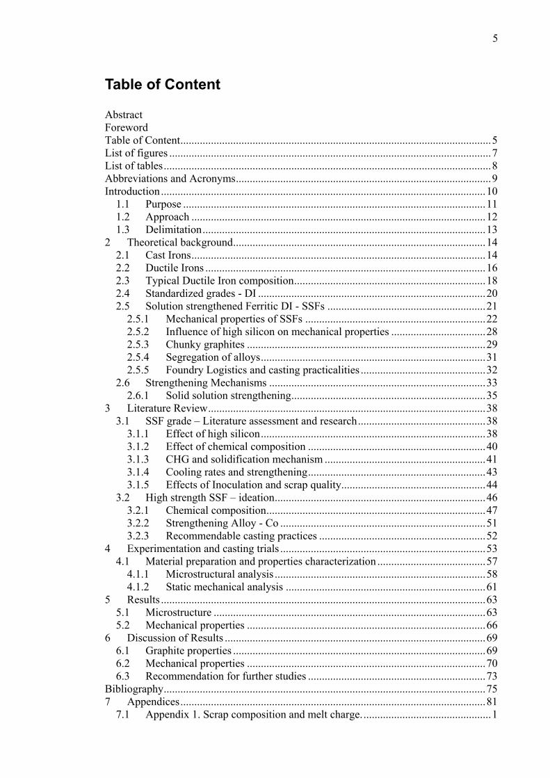
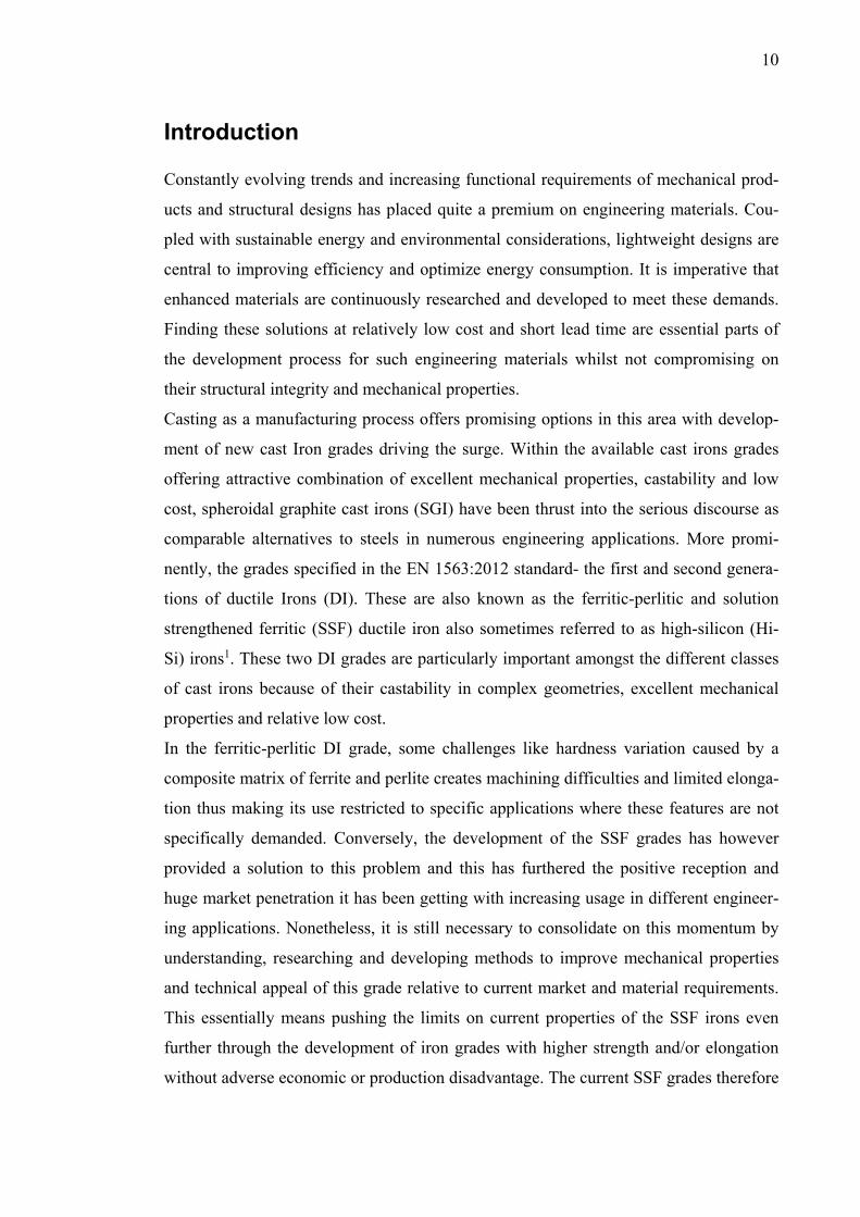
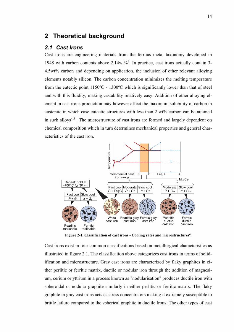
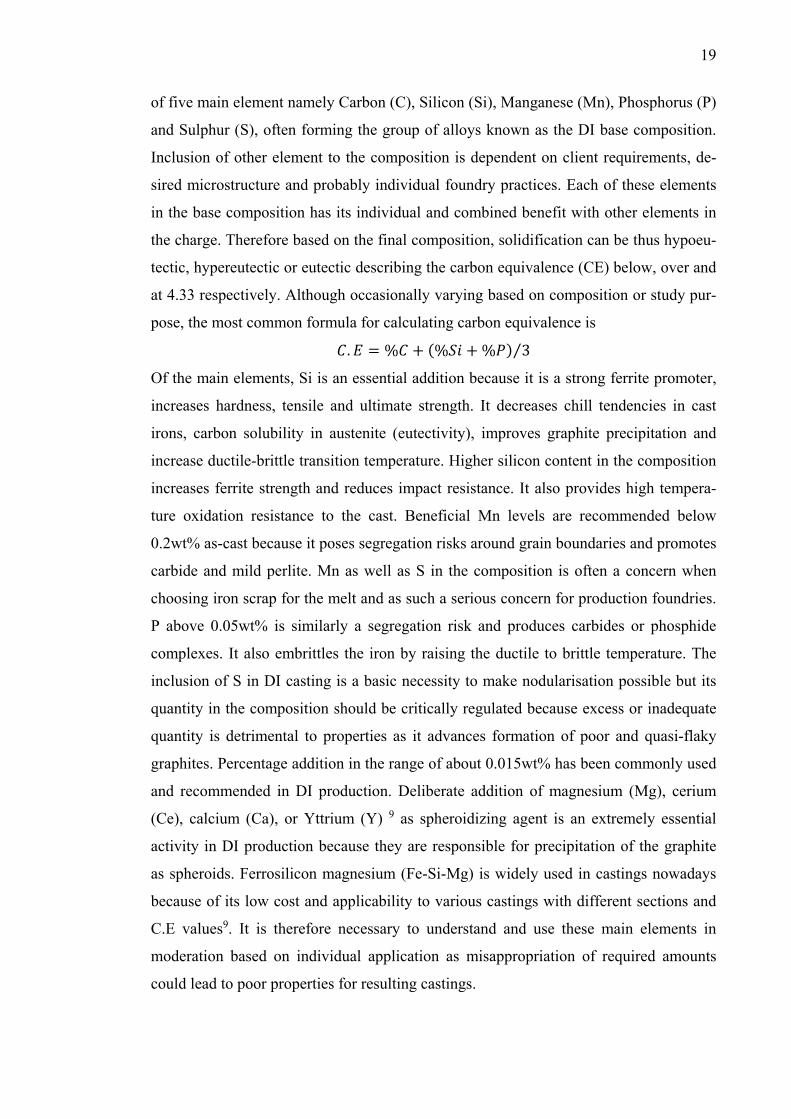
Figure 2-1. Classification of cast irons - Cooling rates and microstructures4.
Cast irons exist in four common classifications based on metallurgical characteristics as
illustrated in figure 2.1. The classification above categorizes cast irons in terms of solid-
ification and microstructure. Gray cast irons are characterized by flaky graphites in ei-
ther perlitic or ferritic matrix, ductile or nodular iron through the addition of magnesi-
um, cerium or yttrium in a process known as "nodularisation" produces ductile iron with
spheroidal or nodular graphite similarly in either perlitic or ferritic matrix. The flaky
graphite in gray cast irons acts as stress concentrators making it extremely susceptible to
brittle failure compared to the spherical graphite in ductile Irons. The other types of cast
15
irons are white irons which are even more brittle because of carbon existing mostly as
cementite in its microstructure4,6. Malleable cast irons are the heat-treated variation of
white irons while the last types are vermicular or compacted-graphite irons which com-
bine microstructural properties of both gray and ductile irons with a worm-like or ver-
micular shaped graphite.
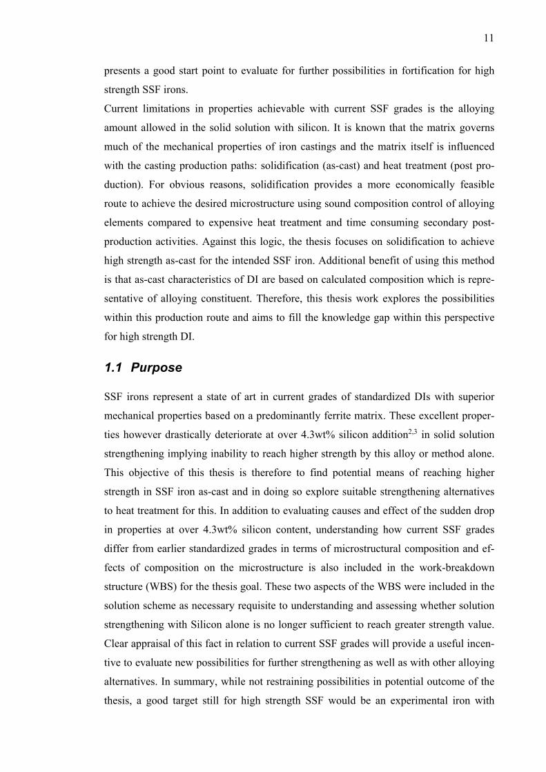
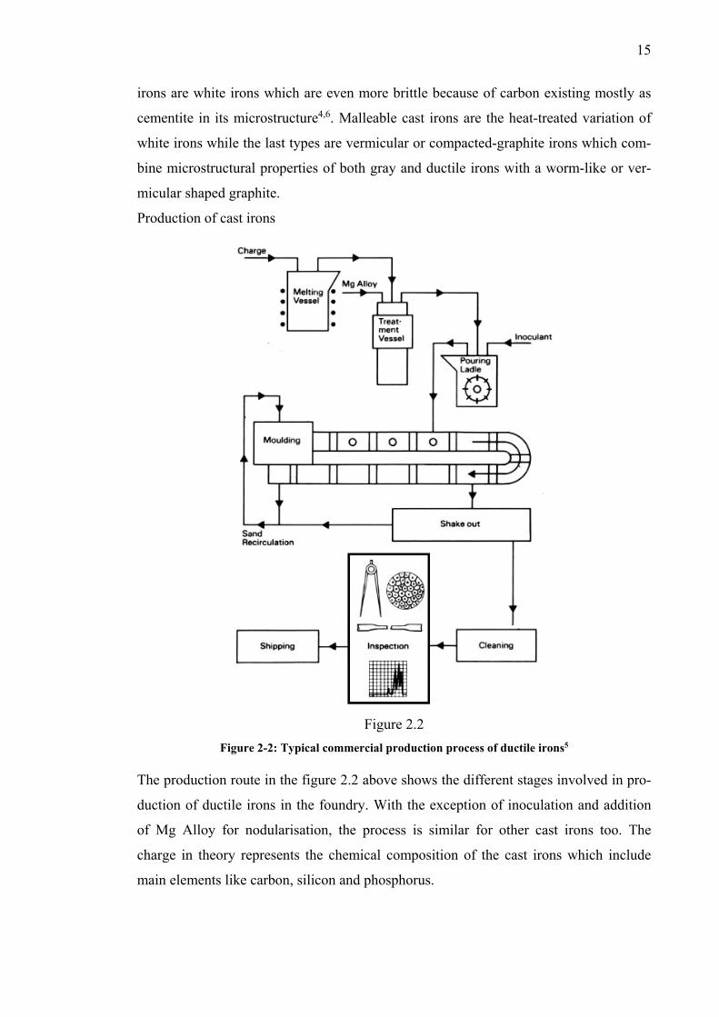
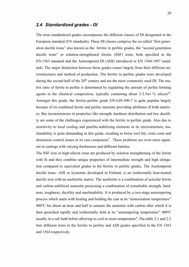
Production of cast irons
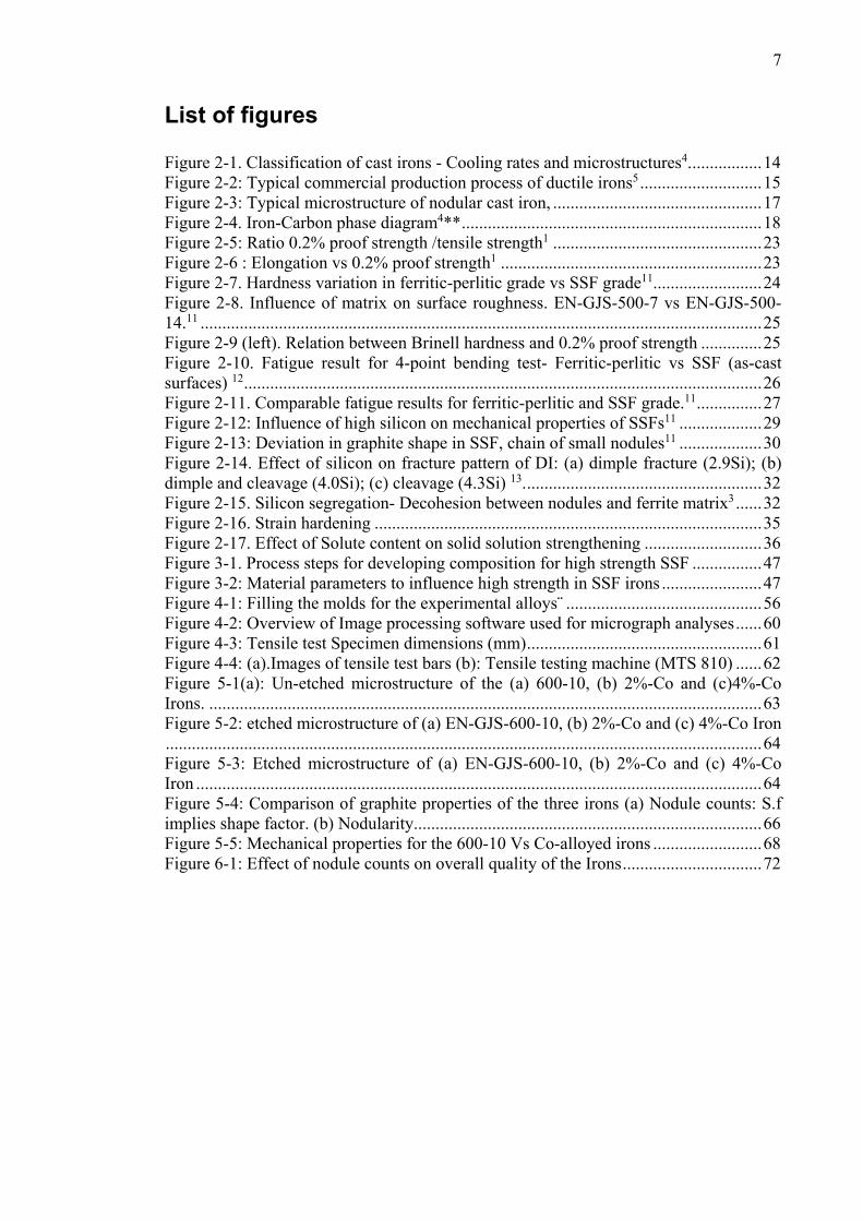
Figure 2.2
Figure 2-2: Typical commercial production process of ductile irons5 The production route in the figure 2.2 above shows the different stages involved in pro-
duction of ductile irons in the foundry. With the exception of inoculation and addition
of Mg Alloy for nodularisation, the process is similar for other cast irons too. The
charge in theory represents the chemical composition of the cast irons which include
main elements like carbon, silicon and phosphorus.
16
2.2 Ductile Irons Ductile irons (DI), also referred to as nodular or spheroidal graphite irons (SGI) are
produced through the addition of either cerium, yttrium or magnesium in the liquid cast
iron melt to precipitate the graphite as spheroids or nodules. As exemplified in the clas-
sification method used in figure 2.1, solidification sequence and composition control of
alloying elements in the chemical composition determines the microstructure of DI re-
sulting in a wide range of grades available today. As the name implies, ductile irons
have significantly higher tensile elongation and substantial strength compared to gray
irons for example, primarily because of the graphite morphology. The spheroidal graph-
ites act as dislocation inhibitors because of its surface area to volume ratio compared to
flaky graphites in gray irons which act as notches or stress concentrators. For DI, the
microstructure comprise micro constituents describing nodule count, matrix structure
and “nodularity” which have significant influence on properties of the iron individually
or in combination6,7. The guidelines on nodularity for DI are designated in the EN-ISO
945-1 dividing nodule forms into categories I to VI, form V and VI being the most op-
timal. The nodularity is integral to mechanical properties such as toughness and elonga-
tion and there is often a strong correlation between deterioration of properties and de-
viation of the nodules from the recommendable forms V, VI. High nodule count is also
very desirable to some mechanical properties and it is one of the benefits of effective
inoculation in DI production.
Inoculation is an important aspect of cast iron production and performed to provide suf-
ficient nucleation sites for dissolved carbon to precipitate as graphite rather than ce-
mentite Fe3C in the iron. This is achieved by preventing undercooling below the meta-
stable eutectic temperature where brittle white iron structures are formed8. Depending
on the cast iron type or chemical reactivity of constituent alloys in the charge, the inocu-
lants may be added in either the treatment vessel or pouring ladle as in schematic de-
picted in figure 2.2. Available grades of DI exist typically from fully ferritic to fully
perlitic depending on the chemical composition, production method or grade. The per-
centage ratio of ferrite and perlite in the matrix structure typically governs the material
strength. DI as-cast are commonly pearlite which is a micro-constituent comprising al-
ternating layers of ferrite and cementite. The ferrite matrix which represent the pure
phase of iron can be derived through heat treatment or appropriate alloying composi-
tion. Ferrite has low strength and hardness but relatively high toughness and ductility
while perlite has high strength and hardness but low ductility. As mentioned earlier,
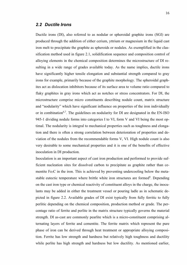
17
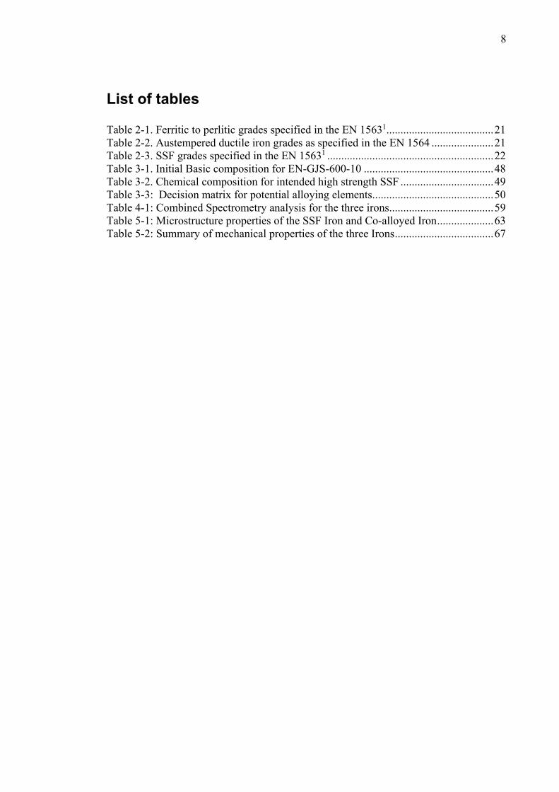
both types of matrices can be produced as-cast in DI completely or in shared ratio
through controlled heat-treatment, composition control or solidification sequence. Fig-
ure 2.3 shows the three possible DI microstructures attainable from either of the process
mentioned above and as seen from all three microstructure, a common feature are the
nodular graphites.
(a) (b) (c)
Figure 2-3: Typical microstructure of nodular cast iron, (a) Fully ferritic matrix, (b) ferritic-perlitic matrix, (c) fully perlitic matrix.
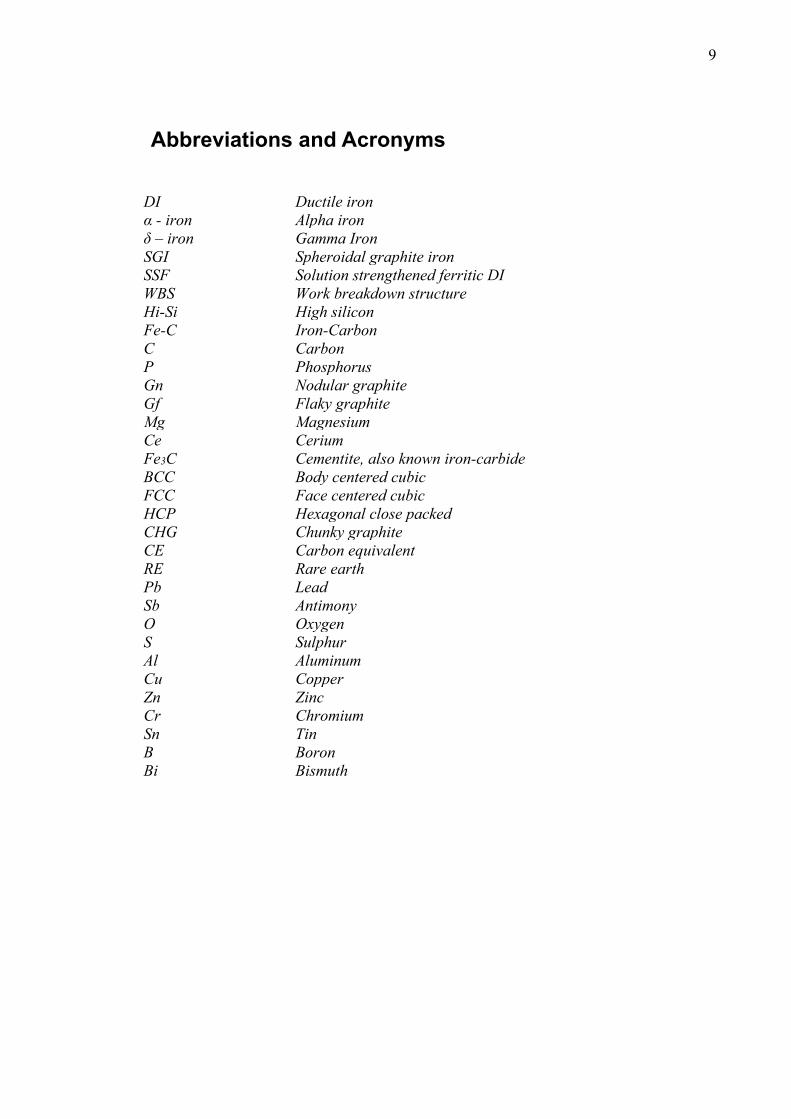
The iron-carbon diagram (Fe-C phase diagram) in figure 2.4 describes the different
phases of iron relative to solubility limits of carbon. This diagram best explains the so-
lidification process of DI producing those microstructures above. The Fe-C diagram
shown is only a portion of the whole diagram ending at a maximum carbon composition
limit 6.7wt% with a cementite matrix. In practice, this means all steels and cast irons
have lesser carbon content4. Pure iron can exist in three phase forms when melted as
indicated on the leftmost axis. Ferrite or α-iron at room temperature up to 912oC with
BCC crystal structure and maximum carbon solubility of 0.22wt%, austenite with a
FCC crystal structure upon further heating up till 1394oC and as δ-iron up until 1538oC
which is the melting point of iron. The δ-iron is structurally the same as α-iron, the only
difference being the temperature ranges in which they exist. Phase transformation with
respect to austenite is of prime importance to cast irons, it has maximum carbon solubil-

18
ity of 2.14wt% at 1147oC and the FCC crystal structure permits this amount due to larg-
er interstices for carbon in the solid solution. Austenite does not exist below the lower
critical temperature- 727oC at which point the metastable cementite Fe3C forms.
Figure 2-4. Iron-Carbon phase diagram4**
**Solid curve represents the metastable system Fe-Fe3C and dashed curves represent the stable system iron-graphite
2.3 Typical Ductile Iron composition DI are used in many applications where combined qualities of strength and ductility are
essential. In contrast to gray iron for instance, strength in DI is doubled and elongation
raised by factor 204. These properties are attributed to primary chemical composition of
DI which might of course vary depending on foundries and influenced by purity level of
scrap metal used in the melt charge during castings. Typical composition of DI consist
19
of five main element namely Carbon (C), Silicon (Si), Manganese (Mn), Phosphorus (P)
and Sulphur (S), often forming the group of alloys known as the DI base composition.
Inclusion of other element to the composition is dependent on client requirements, de-
sired microstructure and probably individual foundry practices. Each of these elements
in the base composition has its individual and combined benefit with other elements in
the charge. Therefore based on the final composition, solidification can be thus hypoeu-
tectic, hypereutectic or eutectic describing the carbon equivalence (CE) below, over and
at 4.33 respectively. Although occasionally varying based on composition or study pur-
pose, the most common formula for calculating carbon equivalence is
𝐶𝐶.𝐸𝐸 = %𝐶𝐶 + (%𝑆𝑆𝑆𝑆 + %𝑃𝑃) 3⁄
Of the main elements, Si is an essential addition because it is a strong ferrite promoter,
increases hardness, tensile and ultimate strength. It decreases chill tendencies in cast
irons, carbon solubility in austenite (eutectivity), improves graphite precipitation and
increase ductile-brittle transition temperature. Higher silicon content in the composition
increases ferrite strength and reduces impact resistance. It also provides high tempera-
ture oxidation resistance to the cast. Beneficial Mn levels are recommended below
0.2wt% as-cast because it poses segregation risks around grain boundaries and promotes
carbide and mild perlite. Mn as well as S in the composition is often a concern when
choosing iron scrap for the melt and as such a serious concern for production foundries.
P above 0.05wt% is similarly a segregation risk and produces carbides or phosphide
complexes. It also embrittles the iron by raising the ductile to brittle temperature. The
inclusion of S in DI casting is a basic necessity to make nodularisation possible but its
quantity in the composition should be critically regulated because excess or inadequate
quantity is detrimental to properties as it advances formation of poor and quasi-flaky
graphites. Percentage addition in the range of about 0.015wt% has been commonly used
and recommended in DI production. Deliberate addition of magnesium (Mg), cerium
(Ce), calcium (Ca), or Yttrium (Y) 9 as spheroidizing agent is an extremely essential
activity in DI production because they are responsible for precipitation of the graphite
as spheroids. Ferrosilicon magnesium (Fe-Si-Mg) is widely used in castings nowadays
because of its low cost and applicability to various castings with different sections and
C.E values9. It is therefore necessary to understand and use these main elements in
moderation based on individual application as misappropriation of required amounts
could lead to poor properties for resulting castings.
20
2.4 Standardized grades - DI The term standardized grades encompasses the different classes of DI designated in the
European standard (EN standards). These DI classes comprise the so-called “first gener-
ation ductile irons” also known as the ferritic to perlitic grades, the “second generation
ductile irons” or solution-strengthened ferritic (SSF) irons, both specified in the
EN:1563 standard and the Austempered DI (ADI) introduced in EN 1564:1997 stand-
ards. The major distinction between these grades comes largely from their different mi-
crostructures and method of production. The ferritic to perlitic grades were developed
during the second half of the 20th century and are the more commonly used DI. The ma-
trix ratio of ferrite to perlite is determined by regulating the amount of perlite forming
agents in the chemical composition, typically containing about 2-2.5wt % silicon10.
Amongst this grade, the ferritic-perlitic grade EN-GJS-500-7 is quite popular largely
because of its combined ferrite and perlite structure providing attributes of both matrix-
es. But inconsistencies in properties like strength, hardness distribution and low ductili-
ty are some of the challenges experienced with the ferritic to perlitic grade. Also due to
sensitivity to local cooling and pearlite-stabilizing elements in its microstructure, ma-
chinability is quite demanding in this grade, resulting in lower tool life, extra costs and
dimension control issues in its cast component7. These problems are even more appar-
ent in castings with varying thicknesses and different batches.
The SSF iron or high-silicon irons are produced by solution strengthening of the ferrite
with Si and they combine unique properties of intermediate strength and high elonga-
tion compared to equivalent grades in the ferritic to perlitic grades. The Austempered
ductile irons -ADI or kymenite developed in Finland, is an isothermally heat-treated
ductile iron with an ausferritic matrix. The ausferrite is a combination of acicular ferrite
and carbon-stabilized austenite possessing a combination of remarkable strength, hard-
ness, toughness, ductility and machinability. It is produced by a two-stage austempering
process which starts with heating and holding the cast at its “austenisation temperature”
900oC for about an hour and half to saturate the austenite with carbon after which it is
then quenched rapidly and isothermally held at its “austempering temperature” 400oC
usually in a salt bath before allowing to cool at room temperature9. The table 2.1 and 2.2
lists different irons in the ferritic to perlitic and ADI grades specified in the EN 1563
and 1564 respectively.
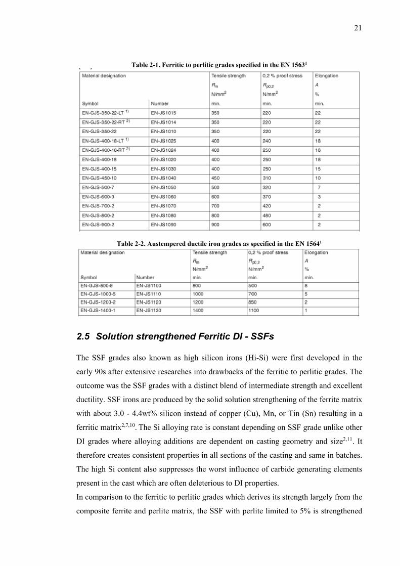
21
Table 2-1. Ferritic to perlitic grades specified in the EN 15631
Table 2-2. Austempered ductile iron grades as specified in the EN 15641
2.5 Solution strengthened Ferritic DI - SSFs The SSF grades also known as high silicon irons (Hi-Si) were first developed in the
early 90s after extensive researches into drawbacks of the ferritic to perlitic grades. The
outcome was the SSF grades with a distinct blend of intermediate strength and excellent
ductility. SSF irons are produced by the solid solution strengthening of the ferrite matrix
with about 3.0 - 4.4wt% silicon instead of copper (Cu), Mn, or Tin (Sn) resulting in a
ferritic matrix2,7,10. The Si alloying rate is constant depending on SSF grade unlike other
DI grades where alloying additions are dependent on casting geometry and size2,11. It
therefore creates consistent properties in all sections of the casting and same in batches.
The high Si content also suppresses the worst influence of carbide generating elements
present in the cast which are often deleterious to DI properties.
In comparison to the ferritic to perlitic grades which derives its strength largely from the
composite ferrite and perlite matrix, the SSF with perlite limited to 5% is strengthened
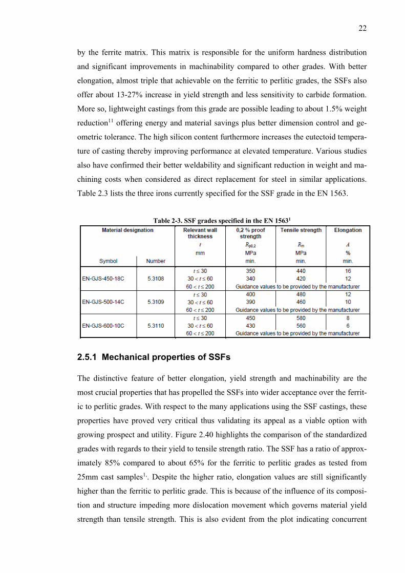
22
by the ferrite matrix. This matrix is responsible for the uniform hardness distribution
and significant improvements in machinability compared to other grades. With better
elongation, almost triple that achievable on the ferritic to perlitic grades, the SSFs also
offer about 13-27% increase in yield strength and less sensitivity to carbide formation.
More so, lightweight castings from this grade are possible leading to about 1.5% weight
reduction11 offering energy and material savings plus better dimension control and ge-
ometric tolerance. The high silicon content furthermore increases the eutectoid tempera-
ture of casting thereby improving performance at elevated temperature. Various studies
also have confirmed their better weldability and significant reduction in weight and ma-
chining costs when considered as direct replacement for steel in similar applications.
Table 2.3 lists the three irons currently specified for the SSF grade in the EN 1563.
Table 2-3. SSF grades specified in the EN 15631
2.5.1 Mechanical properties of SSFs The distinctive feature of better elongation, yield strength and machinability are the
most crucial properties that has propelled the SSFs into wider acceptance over the ferrit-
ic to perlitic grades. With respect to the many applications using the SSF castings, these
properties have proved very critical thus validating its appeal as a viable option with
growing prospect and utility. Figure 2.40 highlights the comparison of the standardized
grades with regards to their yield to tensile strength ratio. The SSF has a ratio of approx-
imately 85% compared to about 65% for the ferritic to perlitic grades as tested from
25mm cast samples1,. Despite the higher ratio, elongation values are still significantly
higher than the ferritic to perlitic grade. This is because of the influence of its composi-
tion and structure impeding more dislocation movement which governs material yield
strength than tensile strength. This is also evident from the plot indicating concurrent
23
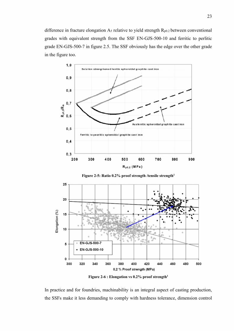
difference in fracture elongation A5 relative to yield strength Rp0.2 between conventional
grades with equivalent strength from the SSF EN-GJS-500-10 and ferritic to perlitic
grade EN-GJS-500-7 in figure 2.5. The SSF obviously has the edge over the other grade
in the figure too.
Figure 2-5: Ratio 0.2% proof strength /tensile strength1
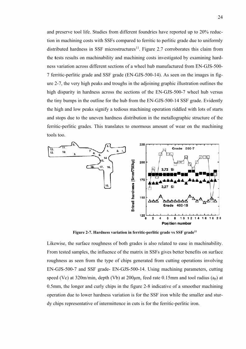
Figure 2-6 : Elongation vs 0.2% proof strength1
In practice and for foundries, machinability is an integral aspect of casting production,
the SSFs make it less demanding to comply with hardness tolerance, dimension control
24
and preserve tool life. Studies from different foundries have reported up to 20% reduc-
tion in machining costs with SSFs compared to ferritic to perlitic grade due to uniformly
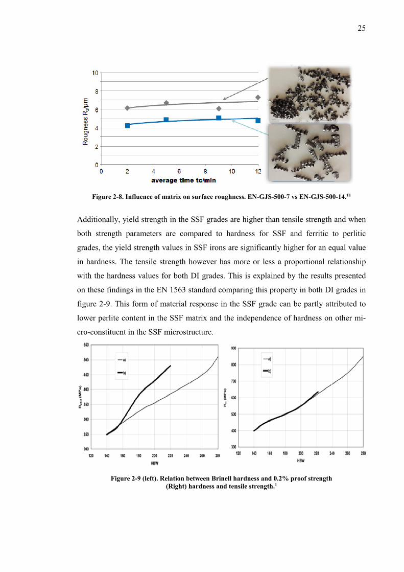
distributed hardness in SSF microstructures11. Figure 2.7 corroborates this claim from
the tests results on machinability and machining costs investigated by examining hard-
ness variation across different sections of a wheel hub manufactured from EN-GJS-500-
7 ferritic-perlitic grade and SSF grade (EN-GJS-500-14). As seen on the images in fig-
ure 2-7, the very high peaks and troughs in the adjoining graphic illustration outlines the
high disparity in hardness across the sections of the EN-GJS-500-7 wheel hub versus
the tiny bumps in the outline for the hub from the EN-GJS-500-14 SSF grade. Evidently
the high and low peaks signify a tedious machining operation riddled with lots of starts
and stops due to the uneven hardness distribution in the metallographic structure of the
ferritic-perlitic grades. This translates to enormous amount of wear on the machining
tools too.
Figure 2-7. Hardness variation in ferritic-perlitic grade vs SSF grade11
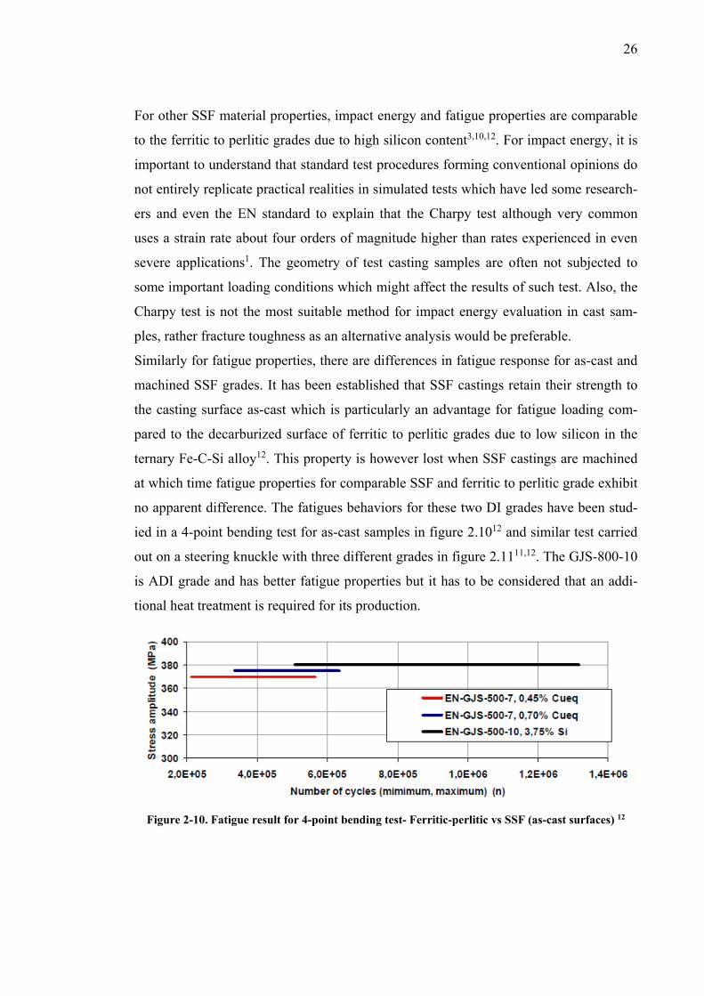
Likewise, the surface roughness of both grades is also related to ease in machinability.
From tested samples, the influence of the matrix in SSFs gives better benefits on surface
roughness as seen from the type of chips generated from cutting operations involving
EN-GJS-500-7 and SSF grade- EN-GJS-500-14. Using machining parameters, cutting
speed (Vc) at 320m/min, depth (Vb) at 200μm, feed rate 0.15mm and tool radius (ap) at
0.5mm, the longer and curly chips in the figure 2-8 indicative of a smoother machining
operation due to lower hardness variation is for the SSF iron while the smaller and stur-
dy chips representative of intermittence in cuts is for the ferritic-perlitic iron.
25
Figure 2-8. Influence of matrix on surface roughness. EN-GJS-500-7 vs EN-GJS-500-14.11
Additionally, yield strength in the SSF grades are higher than tensile strength and when
both strength parameters are compared to hardness for SSF and ferritic to perlitic
grades, the yield strength values in SSF irons are significantly higher for an equal value
in hardness. The tensile strength however has more or less a proportional relationship
with the hardness values for both DI grades. This is explained by the results presented
on these findings in the EN 1563 standard comparing this property in both DI grades in
figure 2-9. This form of material response in the SSF grade can be partly attributed to
lower perlite content in the SSF matrix and the independence of hardness on other mi-
cro-constituent in the SSF microstructure.
Figure 2-9 (left). Relation between Brinell hardness and 0.2% proof strength
(Right) hardness and tensile strength.1
26
For other SSF material properties, impact energy and fatigue properties are comparable
to the ferritic to perlitic grades due to high silicon content3,10,12. For impact energy, it is
important to understand that standard test procedures forming conventional opinions do
not entirely replicate practical realities in simulated tests which have led some research-
ers and even the EN standard to explain that the Charpy test although very common
uses a strain rate about four orders of magnitude higher than rates experienced in even
severe applications1. The geometry of test casting samples are often not subjected to
some important loading conditions which might affect the results of such test. Also, the
Charpy test is not the most suitable method for impact energy evaluation in cast sam-
ples, rather fracture toughness as an alternative analysis would be preferable.
Similarly for fatigue properties, there are differences in fatigue response for as-cast and
machined SSF grades. It has been established that SSF castings retain their strength to
the casting surface as-cast which is particularly an advantage for fatigue loading com-
pared to the decarburized surface of ferritic to perlitic grades due to low silicon in the
ternary Fe-C-Si alloy12. This property is however lost when SSF castings are machined
at which time fatigue properties for comparable SSF and ferritic to perlitic grade exhibit
no apparent difference. The fatigues behaviors for these two DI grades have been stud-
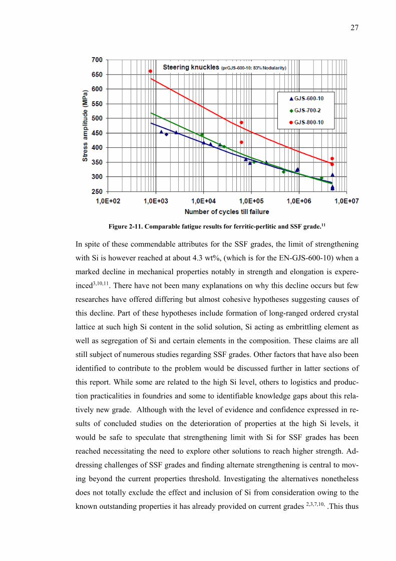
ied in a 4-point bending test for as-cast samples in figure 2.1012 and similar test carried
out on a steering knuckle with three different grades in figure 2.1111,12. The GJS-800-10
is ADI grade and has better fatigue properties but it has to be considered that an addi-
tional heat treatment is required for its production.
Figure 2-10. Fatigue result for 4-point bending test- Ferritic-perlitic vs SSF (as-cast surfaces) 12
27
Figure 2-11. Comparable fatigue results for ferritic-perlitic and SSF grade.11
In spite of these commendable attributes for the SSF grades, the limit of strengthening
with Si is however reached at about 4.3 wt%, (which is for the EN-GJS-600-10) when a
marked decline in mechanical properties notably in strength and elongation is expere-
inced3,10,11. There have not been many explanations on why this decline occurs but few
researches have offered differing but almost cohesive hypotheses suggesting causes of
this decline. Part of these hypotheses include formation of long-ranged ordered crystal
lattice at such high Si content in the solid solution, Si acting as embrittling element as
well as segregation of Si and certain elements in the composition. These claims are all
still subject of numerous studies regarding SSF grades. Other factors that have also been
identified to contribute to the problem would be discussed further in latter sections of
this report. While some are related to the high Si level, others to logistics and produc-
tion practicalities in foundries and some to identifiable knowledge gaps about this rela-
tively new grade. Although with the level of evidence and confidence expressed in re-
sults of concluded studies on the deterioration of properties at the high Si levels, it
would be safe to speculate that strengthening limit with Si for SSF grades has been
reached necessitating the need to explore other solutions to reach higher strength. Ad-
dressing challenges of SSF grades and finding alternate strengthening is central to mov-
ing beyond the current properties threshold. Investigating the alternatives nonetheless
does not totally exclude the effect and inclusion of Si from consideration owing to the
known outstanding properties it has already provided on current grades 2,3,7,10, .This thus
28
broadens the possibilities of working with and around current SSF composition. The
main challenges of the SSF grades although not only limited to the Si amount has ad-
versely culminated in some undesirable effect on strength and elongation and like in
other DI grades, the amount of different alloying elements in the chemical composition
also plays a role in this problem and these would be examined in the next section to
create a better perception of what the properties limitations are and why they exist.
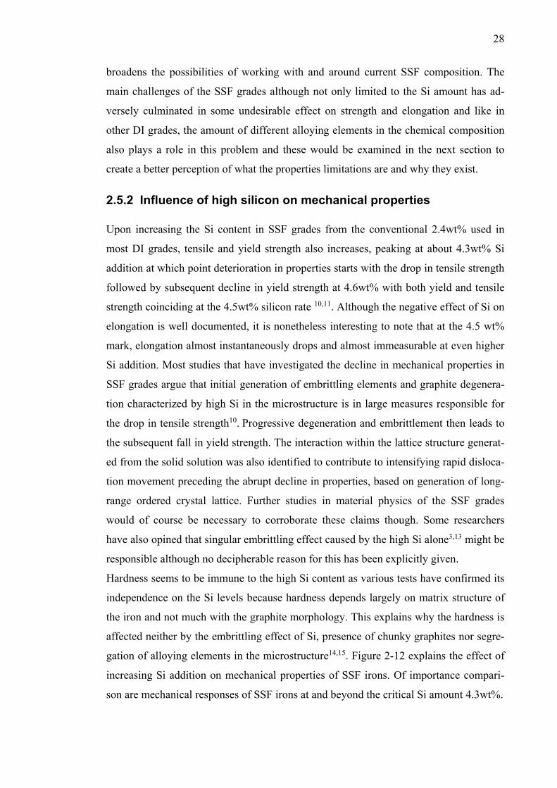
2.5.2 Influence of high silicon on mechanical properties Upon increasing the Si content in SSF grades from the conventional 2.4wt% used in
most DI grades, tensile and yield strength also increases, peaking at about 4.3wt% Si
addition at which point deterioration in properties starts with the drop in tensile strength
followed by subsequent decline in yield strength at 4.6wt% with both yield and tensile
strength coinciding at the 4.5wt% silicon rate 10,11. Although the negative effect of Si on
elongation is well documented, it is nonetheless interesting to note that at the 4.5 wt%
mark, elongation almost instantaneously drops and almost immeasurable at even higher
Si addition. Most studies that have investigated the decline in mechanical properties in
SSF grades argue that initial generation of embrittling elements and graphite degenera-
tion characterized by high Si in the microstructure is in large measures responsible for
the drop in tensile strength10. Progressive degeneration and embrittlement then leads to
the subsequent fall in yield strength. The interaction within the lattice structure generat-
ed from the solid solution was also identified to contribute to intensifying rapid disloca-
tion movement preceding the abrupt decline in properties, based on generation of long-
range ordered crystal lattice. Further studies in material physics of the SSF grades
would of course be necessary to corroborate these claims though. Some researchers
have also opined that singular embrittling effect caused by the high Si alone3,13 might be
responsible although no decipherable reason for this has been explicitly given.
Hardness seems to be immune to the high Si content as various tests have confirmed its
independence on the Si levels because hardness depends largely on matrix structure of
the iron and not much with the graphite morphology. This explains why the hardness is
affected neither by the embrittling effect of Si, presence of chunky graphites nor segre-
gation of alloying elements in the microstructure14,15. Figure 2-12 explains the effect of
increasing Si addition on mechanical properties of SSF irons. Of importance compari-
son are mechanical responses of SSF irons at and beyond the critical Si amount 4.3wt%.
29
Figure 2-12: Influence of high silicon on mechanical properties of SSFs11
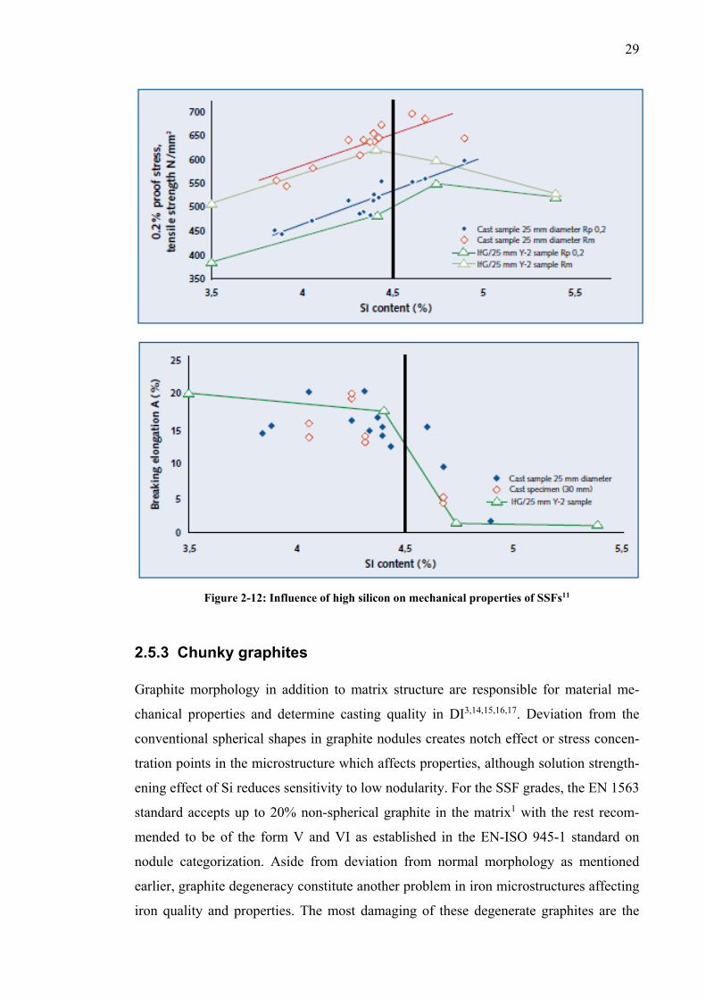
2.5.3 Chunky graphites Graphite morphology in addition to matrix structure are responsible for material me-
chanical properties and determine casting quality in DI3,14,15,16,17. Deviation from the
conventional spherical shapes in graphite nodules creates notch effect or stress concen-
tration points in the microstructure which affects properties, although solution strength-
ening effect of Si reduces sensitivity to low nodularity. For the SSF grades, the EN 1563
standard accepts up to 20% non-spherical graphite in the matrix1 with the rest recom-
mended to be of the form V and VI as established in the EN-ISO 945-1 standard on
nodule categorization. Aside from deviation from normal morphology as mentioned
earlier, graphite degeneracy constitute another problem in iron microstructures affecting
iron quality and properties. The most damaging of these degenerate graphites are the
30
branched and interconnected degenerated graphites often occurring in the thermal center
of DI castings14. They are commonly referred to as chunky graphites (CHG).
Heavy section DI castings with large wall thickness (typically larger than 60mm)2 re-
quiring long solidification time have in particular shown more susceptibility to CHG.
The presence of this form of graphites in these type of castings especially with SSF
irons have proven detrimental to properties such as ductility and UTS although with
lesser effect on Brinell hardness and yield strength14,20. Deeply etched images from SSF
cast samples in figure 2.13 reveal presence of CHG in DI casting and as manifested in
the images, they macroscopically resemble a cluster of degenerated graphite in the mi-
crostructure. The existence of CHG is not entirely new to DI castings but has apparently
not been discussed with much fervor until its effects on the properties of SSF grades
were examined.
Different suggestions on causes of CHG in DI grades vary from inoculation practices in
different foundries relating to presence of Oxygen and Sulphur in the cast to changing
melt conditions during solidification to micro-segregation of alloying element in the
composition. The hypothesis relating to shortage of Oxygen and Sulphur to inoculation
seems credible because tests on reducing CHG through supplemental increase of oxy-
gen and Sulphur in the melt while inoculating have recorded sizeable reduction in
CHG8. Change in melt condition during solidification might prove to be more challeng-
ing to control especially for thicker cast sections since CHG typically form at the ther-
mal center. More so, oxygen shortage can also be attributed to the presence of strong
oxide formers like Aluminum, Calcium, cerium and other rare-earth (RE) metal in the
melt.
Figure 2-13: Deviation in graphite shape in SSF, chain of small nodules11
31
Studies and foundry experiences have argued that enormous mass, longer solidification
time are some of the predisposing factors in heavy section castings often precipitating
graphite degeneration in normal DI. This is similar in SSF castings because the high Si
content coupled with foundry practices like inoculation, pouring temperature, solidifica-
tion conditions and purity level of the melt all affect graphite degeneracy10,13,17.
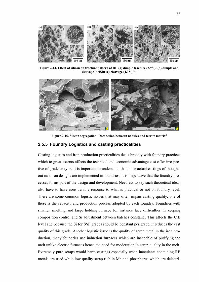
2.5.4 Segregation of alloys Evaluation of current studies on SSFs and fractograph analysis from ruptured samples
show mechanical resistance to failure is also impaired by Si and Mn segregation around
eutectic cell regions of the iron3,13. Si segregates typically around the graphite nodules
and eutectic cell areas while Mn is sequestered usually at cell boundaries in the ana-
lyzed SSF samples. This promotes interfacial weakness in the micro-constituents of the
iron and eliminates bonding forces between the nodules and ferrite matrix as explained
in studies assessing fracture patterns in SSF iron3. Standard casting practices offers rec-
ommendable guidelines on how to minimize these segregations but variations in found-
ry processes does not entirely guarantee properties in SSF grades totally devoid this
problem at either production level or in compositions. Analysis of fractograph have also
indicated failure pattern consistent with dislocation movement and cracks propagated at
areas in the microstructure where the segregations are highest. The effect of segregated
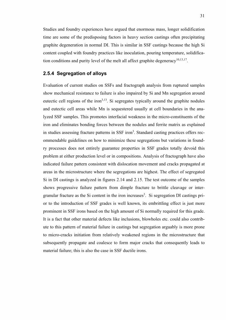
Si in DI castings is analyzed in figures 2.14 and 2.15. The test outcome of the samples
shows progressive failure pattern from dimple fracture to brittle cleavage or inter-
granular fracture as the Si content in the iron increases3. Si segregation DI castings pri-
or to the introduction of SSF grades is well known, its embrittling effect is just more
prominent in SSF irons based on the high amount of Si normally required for this grade.
It is a fact that other material defects like inclusions, blowholes etc. could also contrib-
ute to this pattern of material failure in castings but segregation arguably is more prone
to micro-cracks initiation from relatively weakened regions in the microstructure that
subsequently propagate and coalesce to form major cracks that consequently leads to
material failure; this is also the case in SSF ductile irons.
32
Figure 2-14. Effect of silicon on fracture pattern of DI: (a) dimple fracture (2.9Si); (b) dimple and
cleavage (4.0Si); (c) cleavage (4.3Si) 13.
Figure 2-15. Silicon segregation- Decohesion between nodules and ferrite matrix3
2.5.5 Foundry Logistics and casting practicalities Casting logistics and iron production practicalities deals broadly with foundry practices
which to great extents affects the technical and economic advantage cast offer irrespec-
tive of grade or type. It is important to understand that since actual castings of thought-
out cast iron designs are implemented in foundries, it is imperative that the foundry pro-
cesses forms part of the design and development. Needless to say such theoretical ideas
also have to have considerable recourse to what is practical or not on foundry level.
There are some common logistic issues that may often impair casting quality, one of
these is the capacity and production process adopted by each foundry. Foundries with
smaller smelting and large holding furnace for instance face difficulties in keeping
composition control and Si adjustment between batches constant8. This affects the C.E
level and because the Si for SSF grades should be constant per grade, it reduces the cast
quality of this grade. Another logistic issue is the quality of scrap metal in the iron pro-
duction, many foundries use induction furnaces which are incapable of purifying the
melt unlike electric furnaces hence the need for moderation in scrap quality in the melt.
Extremely pure scraps would harm castings especially when inoculants containing RE
metals are used while low quality scrap rich in Mn and phosphorus which are deleteri-

33
ous, perlite and carbide promoting elements affects cast properties. That being said,
high Si in the cast composition have nonetheless been found to counter the combined
effect of these two element at certain levels since controlling their levels in low quality
scrap may sometimes prove impractical3. Also in terms of logistics, return scraps from
initial castings cannot be interchangeably used for different DI grades, which creates an
additional requirement and extra instrumentation for foundries to separate scraps.
Lastly, the level of knowledge and awareness concerning cast irons in general as engi-
neering materials are still lacking compared to steels. There are multiple applications
currently utilizing steels where cast irons would adequately suffice and offer compara-
ble properties at better technical and economic advantage. This problem affects the level
of researches and studies into DI and particularly, the new SSF grades.
In summary, the points discussed in this section are major challenges recognized from
studies into DI production with specific focus on the SSF grade. Design approach to
getting more out of this grade is to sufficiently address present challenges and formulate
solutions around them. Comprehensive reviews on current studies have identified fac-
tors such as the embrittling effect of silicon, susceptibility to formation of CHG, silicon
and alloy segregation as well as production practicalities as the some of the crippling
factors affecting the SSF grade.
2.6 Strengthening Mechanisms The underlying principle in material strengthening mechanism is restricting the ease of
dislocation movement across the crystal structure of the metal lattice of the material.
This in essence means increasing the mechanical forces required to initiate plastic de-
formation which is a function of microscopic dislocation movement in the lattice. Three
conventional ways exist to strengthen polycrystalline metals through lattice disruption
and as would be seen in their description, these methods are in fact, introduction of
some form of defect into the material structure to stem the intensity of dislocation
movement. The three methods are grain size reduction, solid solution strengthening and
strain hardening. These mechanisms are suitable for single-phase metals and not typi-
cally suitable for multi-phase metals.
Other strengthening methods such Precipitation hardening, martensitic hardening etc.
are some examples of strengthening techniques used for multiphase alloys. Practically,
some of these strengthening methods like precipitation hardening are quite difficult to
even implement with cast irons. Graphite structures can be severely affected by the high
34
treatment times and temperatures that often accompany these strengthening method and
also formation of elements often harmful to casting practices (-eg nodularisation) can
be precipitated in the process. This and other examples of apparently negative effects of
some strengthening methods on graphitic properties limits the number of available
strengthening options open to cast irons compared to cast steels. The emphasis in this
section would therefore be more on solid-solution strengthening with some brief intro-
duction to other similar methods.
Grain size reduction relies on greater grain boundary area to constrain dislocation mo-
tion. Grain boundaries functionally block dislocation movement causing a huge pile up
at the boundary which consequently leads to driving forces that at some point are strong
enough to traverse across adjacent grains. The bigger the grain and crystallographic
orientation, the larger the area available for dislocations to accumulate as driving force
and propagate. Reduced grain size therefore utilizes an atomic disorder within grain
boundary region resulting in lower dislocation pile up and lesser accumulation of driv-
ing forces. This effectively means larger stress level would be required to move disloca-
tion to adjacent grains as a result of the increased crystallographic disorientation. This
means higher yield strength for the material. Grain size reduction also increases the ma-
terials toughness.
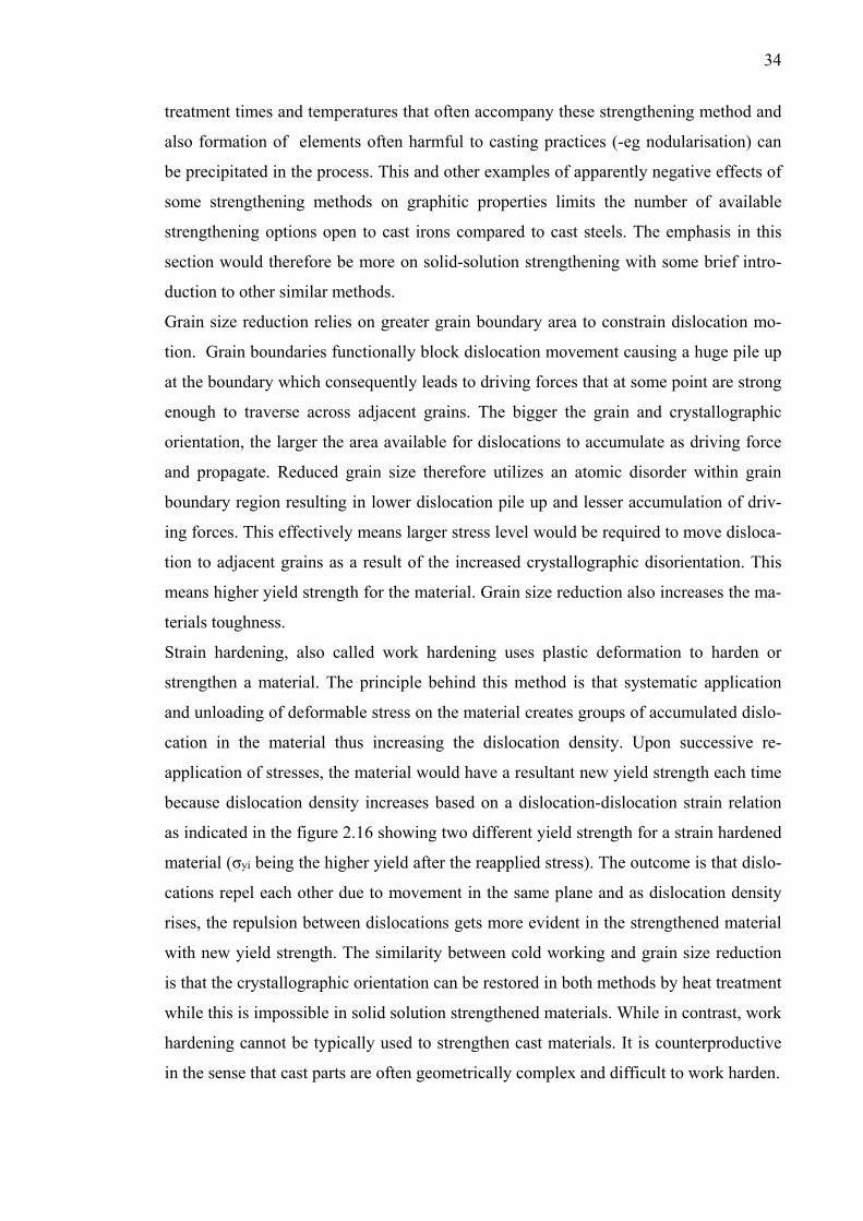
Strain hardening, also called work hardening uses plastic deformation to harden or
strengthen a material. The principle behind this method is that systematic application
and unloading of deformable stress on the material creates groups of accumulated dislo-
cation in the material thus increasing the dislocation density. Upon successive re-
application of stresses, the material would have a resultant new yield strength each time
because dislocation density increases based on a dislocation-dislocation strain relation
as indicated in the figure 2.16 showing two different yield strength for a strain hardened
material (σyi being the higher yield after the reapplied stress). The outcome is that dislo-
cations repel each other due to movement in the same plane and as dislocation density
rises, the repulsion between dislocations gets more evident in the strengthened material
with new yield strength. The similarity between cold working and grain size reduction
is that the crystallographic orientation can be restored in both methods by heat treatment
while this is impossible in solid solution strengthened materials. While in contrast, work
hardening cannot be typically used to strengthen cast materials. It is counterproductive
in the sense that cast parts are often geometrically complex and difficult to work harden.
35
Figure 2-16. Strain hardening
2.6.1 Solid solution strengthening Solid solution strengthening is implemented through the introduction of impurity atoms
into the crystal structure of pure metals. It is one of the three alternatives available for
alloying as a strengthening option, the other two being dispersion strengthening and
precipitation hardening which are used for multiphase metals. Solid solution strengthen-
ing introduces these impurity atoms in the host metal structure either by substitution or
interstitially and they impose a lattice strain on neighboring host atoms causing re-
striction in progressive dislocation movement in the crystal lattice4. These solute atoms
isolates around dislocation in such manner that it relieves the overall strain energy
equaling some of the strain previously induced by dislocations in the surrounding lat-
tice.
In substitution solid solution strengthening, the solute and solvent atoms are typically
similar in size and as the name implies, some of the solvent atoms are substituted by the
impurity (solute) atoms in the lattice. Interstitial solution strengthening exploits the
smaller size of the solute atoms to occupy interstices in the solvent lattice. Solid solu-
tions are compositionally homogenous as the solute atoms are randomly distributed
across the material matrix. Practically, solid solution strengthening depends on the solu-
bility of the solute atoms in the host matrix and is largely affected by a number of fac-
tors to be effective. These factors include Atomic size, crystal structure, solute concen-
tration and valence of the solute atoms (for ionic materials). The atomic size factor
specifies according to Huume-Rothery rule is that the difference in atomic radii of so-
36
lute and solvent atom should be less than 15% to minimize the risk of lattice distortion.
It is also effective if the crystal structures of both solute and solvent matrices are similar
and a high valence solute would be readily dissolved in the solvent. The solute atomic
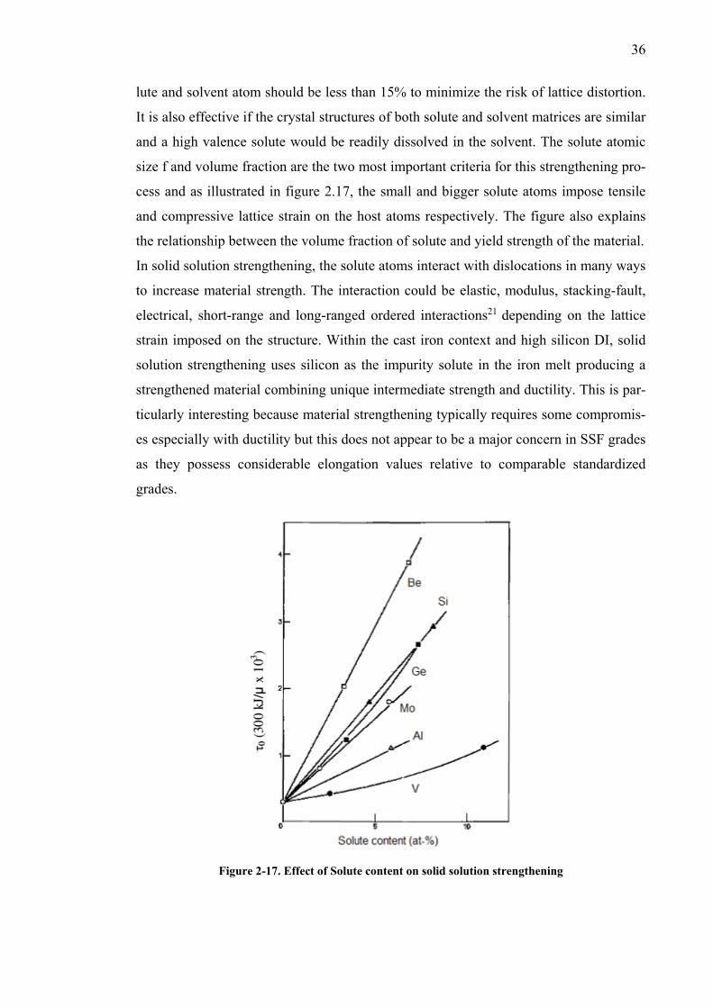
size f and volume fraction are the two most important criteria for this strengthening pro-
cess and as illustrated in figure 2.17, the small and bigger solute atoms impose tensile
and compressive lattice strain on the host atoms respectively. The figure also explains
the relationship between the volume fraction of solute and yield strength of the material.
In solid solution strengthening, the solute atoms interact with dislocations in many ways
to increase material strength. The interaction could be elastic, modulus, stacking-fault,
electrical, short-range and long-ranged ordered interactions21 depending on the lattice
strain imposed on the structure. Within the cast iron context and high silicon DI, solid
solution strengthening uses silicon as the impurity solute in the iron melt producing a
strengthened material combining unique intermediate strength and ductility. This is par-
ticularly interesting because material strengthening typically requires some compromis-
es especially with ductility but this does not appear to be a major concern in SSF grades
as they possess considerable elongation values relative to comparable standardized
grades.
Figure 2-17. Effect of Solute content on solid solution strengthening

37
Other alloying methods for solution strengthening such dispersion strengthening and
precipitation hardening are based on the formation or introduction of second phase ma-
terials or foreign particles which obstruct dislocation movement to improve material
strength. Fiber strengthening and martensitic strengthening are also different methods
for raising material yield strength but all these are suitable for multiphase materials
which are not a focus in this report.
38
3 Literature Review
3.1 SSF grade – Literature assessment and research The solution approach for the thesis objective is exploratory as much as novel in that it
explores possibilities of reaching higher strength in SSF irons as-cast with properties
besting current grades. But reaching the potentials for higher strength in the grades ne-
cessitates a critical understanding of the challenges experienced with current standard-
ized SSF grades and limitations in properties attainable with present method of solution
strengthening with Si.
Using a thematic approach in reviewing existing researches on this grade represents the
core of solution strategy for information scavenging and qualitative outlook on the es-
sentials required to understand the intrinsic potentials and challenges of the SSF grade.
It also enhances the possibility to advance on improvement methods. Researches on
SSF are although limited and relatively unexpansive owing to its level of maturity
amongst engineering materials and market penetration. This situation is expected to and
rapidly changing, judging by growing interests and better understanding of prospects of
the grade. Therefore, this thesis asides its major objective also aims to supplement the
information repository on the SSF grade.
This section reviews different literatures addressing topics and issues identified as sub-
themes of the thesis which are sets of pertinent questions drawn up as guides for choos-
ing relevant literatures to analyze. This approach provide better insights into the state of
art in DI production, examine disparate perspectives of researchers and studies on dif-
ferent casting challenges of standardized grades or quality-augmentation techniques and
then harmonize their inferences for a more coherent understanding of DI castings. This
would supply much needed input for development strategies utilized in the ideation
phase of this thesis work
3.1.1 Effect of high silicon With respect to the high Silicon grades, major obstacles in reaching higher properties
strengthening with Silicon above 4.4wt% have been attributed to the singular embrit-
tling effect caused by the high amount of silicon, graphite degeneracy (commonly
termed chunky graphites (CHG)) and segregation of some alloying element in and
around the eutectic cells10. Characterization overview of SSFs and microstructural eval-
uation of the EN-GJS-500-14 and 600-10 grades examined by Stets et al, (2014) high-
39
lighted the importance of inoculation and solidification mechanism as essential tools in
production of this grade. While this study does not explicitly provide decipherable rea-
sons for the particular embrittling effect of Silicon it mentions, it appeared to suggest at
such high silicon content, generation of long-ranged ordered lattice structure in the re-
sulting solid solution aids rapid extensive dislocation movement across the microstruc-
ture resulting in abrupt material failure. Hung-Mao et al (2003)13, similarly concluded
that the rate of embrittlement experienced in ductile iron is proportional to the increase
in silicon content. Evidence for this assertion was presented in the form of fracture pat-
terns seen on different ductile irons tested with increasing amount of silicon ranging
from dimple failure to brittle cleavages. These modes of failure pattern are representa-
tive of ductile and brittle fracture respectively. Furthermore, it was suggested that the
presence of inclusions and segregation of oxides of magnesium or cerium in the eutectic
cell boundaries further assist the action of Silicon in the evaluated fractograph.
Likewise Larker (2009)8, provided proof that while silicon-rich DI fare remarkably well
at elevated temperatures and thermal cycles because silicon raises the eutectoid temper-
ature, they are also affected by the Silicon content at these stages.
Other challenges encountered with SSF grades identified in this study included the
presence of CHG, dross formation and susceptibility to porosities. Similar results were
also reported by Duit (2013)2 from casting experiences with SSF irons. The report fur-
ther suggested lesser dependence of mechanical properties on nodularity in SSF grades
compared to first generation DIs because nodule shape or graphite morphology allows
the matrix structure determine the mechanical properties of the iron.
Alhussein et al,(2014)3, comments that increased silicon does not affect average grain
size and that the combined effect of Silicon segregation and casting defects is most re-
sponsible for the drastic change in ductility and material resilience at high silicon con-
tents. Using consequential evidences from observing microstructures and failure pat-
terns of high-silicon irons, the study explained the importance of composition on the
initiation and propagation of cracks in SSF grades. Macro-segregation of silicon close to
the graphite nodules causes decohesion between the nodules and matrix during yield
because this level of segregation does not offer much resistance to propagation of dislo-
cation. Larker (2009)8 provided evidences of very comparable impact energy and
slightly better fracture toughness between SSF and ferritic to perlitic grades of equiva-
lent strength. Due to a homogenous ferritic matrix structure precipitated by solid solu-
tion strengthening effect of Silicon, SSF grades have very low hardness variation which
40
translates to better machinability compared to the ferritic to perlitic grades. From a pro-
duction point of view in foundries, this improves dimensional accuracy and geometric
control easier. Bjorkegren and Hamberg (2003)18 and Herfurth (2011)19 agreed with
these conclusions and Herfurth et al explored further on the theoretical links between
the highly homogenous hardness distribution in SSF castings, solidification and cooling
conditions through different forms of castings. It was inferred that continuous castings
as opposed to sand casting provided better cooling conditions favorable for SSF grades,
especially heavy section castings traditionally prone to graphite degeneracy. The results
of this method constituted preemptive studies for casting the GOPAC C500 F19, a high-
ly pressurized hydraulic blocks presented in the research.
3.1.2 Effect of chemical composition The richness in Silicon is not solely responsible for both enhanced properties and chal-
lenges in SSFs, studies have also shown that present limitations in properties can also be
related to influence of other elements in the chemical composition or subversive trace
elements present in scraps used in the casting. Selection and priority of elements in the
chemical composition is key to moving beyond current property thresholds of this grade
(Serrallach et al, 2010)20.
Production of ductile iron through an adequate balance of alloying elements can more
than adequately substitute heat treatment and mechanical properties obtained through
this method according to results obtained from the works of Gonzaga (2013)16, Gonzaga
and Carrasquilla (2005)21 are often better than those obtained through common meth-
ods. It is quite pragmatic to also draw inspiration for improvement ideas from enhance-
ment techniques in other engineering materials for applicable method for the thesis goal.
Steel production and super alloys are interesting areas to look into considering how
these super alloys have in a relatively short time became almost ubiquitous in aero-
space, energy, chemical industries and even medicine. Combination of excellent me-
chanical properties, corrosion resistance and bio-compatibility renders these alloys the
best material choice for many critical applications22. Strengthening mechanisms through
controlled alloying is a popular concept even in steel production.
Gonzaga (2013)16, Gonzaga and Carrasquilla (2005)21 clearly pointed out that graphite
nodularity governs yield and fracture elongation and identified the deleterious effect of
excess manganese (Mn) and phosphorus (P) on ferritic ductile irons. With a similar re-
search outcome, Riposan (2007)23 also recommended that less than 0.03wt% P and no
41
more than 0.2wt% Mn are optimal percentages for both elements in chemical composi-
tion to obtain as-cast ferritic structure in DI. Nonetheless, according Gonzaga and Car-
rasquilla (2005), high silicon in DI nullifies the combined adverse effect of Mn and P in
the composition3,16
One of the primary features of typical compositions for DI is that it is constituted to
reduce the probability of carbide formation, volume fraction of ferrite or perlite in the
microstructure depending on the desired matrix, as well as the graphite properties.
While these conditions as mentioned before could be met with appropriate choice and
amount of elements in the composition, there are secondary factors like inoculation and
solidification sequences that also contribute and should be controlled to get the best
quality castings (Serrallach et al, 201020, Gonzaga (2013)16. Getting either of these fac-
tors wrong affect the outcome and mechanical properties of the casting.
3.1.3 CHG and solidification mechanism Occurrence of chunky graphites in the microstructure is one of the marks of these
aforementioned factors, although it is relatively unclear which of these factors consider-
ably influences this form of graphite. CHG is one of the least understood phenomenon
in casting as there still exist no unified theory addressing its formation or definitive
combative measures. Different researches have discussed its causes and proposed pre-
ventive actions but these are based on their respective angles of study and research
scopes.
For example, Källbom (2005, 2006)15 on solidification sequence in ductile iron attribut-
ed the presence of “degenerate” graphite in the microstructure to solidification mecha-
nism used for individual castings. Since spherical graphites were present in the last so-
lidified areas, it was argued that that chunky graphite forms early during the eutectic
solidification. The study went to propose that the volume percentage of chunky graph-
ites present in the microstructure influences in measurable amount the decline in ulti-
mate tensile strength and fracture elongation of the casting14. Correspondingly, Mu-
hmond & Fredriksson (2013) also believes this form of graphite in high-silicon DI
showed low graphite nucleation potential caused by the absence of Oxygen and Sulphur
in the affected areas. The presence of Sulphur and Oxygen in the melt is a quite compli-
cated topic in relation to graphite growth morphologies in cast irons. In DI for instance,
nodularizing agents like Magnesium and inoculants influences the presence of these
elements which subsequently affects transition in graphite morphology24. Supplemental
42
addition of S and O to reduce shrinkage, chill (carbide formation), sustain continued
graphite nucleation and growth for high quality DI casting was suggested by Skaland
(2009)25 arguing for the use of inoculants containing rare-earth (RE) metal for DI cast-
ings. Using RE metals inoculants should however be a function of the purity level of the
scrap metal because excessive amounts in high purity scrap will promote formation of
chunky graphites26. These studies are indication of the role of Sulphur and Oxygen in
graphite characterization in cast irons. As with most elements in the composition, Sul-
phur and oxygen at moderated levels post-inoculation promotes suitable nuclei for
graphite precipitation with positive effects on nodularity (Riposan et al, 2003)27. The
implications of these studies purporting the continual supply of Sulphur and Oxygen
could be vital to solving the presence of CHG in the microstructure. Low graphite nu-
cleation potential could be addressed through supplemental addition post-inoculation
experimented in the works of Skaland25,28 to reduce the occurrence probability of CHG.
More so, In spite of the higher Carbon and Silicon in ductile irons, the shrinkage and
chilling tendencies in ductile iron is more than in other types of cast irons which is
largely due to difference in graphitization during their respective eutectic solidification.
Contrary views on the formation of CHG was the time-dependent thickening of the aus-
tenite shell in DI which inhibits continuous nucleation of graphite due to low carbon
diffusion rate causing lesser and possibly larger nodular graphites. (Nakae, 2007)29
Larranaga et al (2009)30,31 in agreement with Nakae (2011)32 proposed that in castings
with Cerium, stringent control of cooling and addition of higher amount of Antimony
(Sb) in a proportionate ratio will improve properties of such casts. In castings where RE
metal inoculation is used, addition of Sb or other anti-spherodizing elements was found
to balance out the negative effect of RE metals especially in high-purity melts and large
section casting33 since concentration of Sb or lead (Pb) around the graphite was ex-
pected to stop impending degeneracy. The study notwithstanding does not give compel-
ling evidence that this measure effectively nullifies the presence of CHG because Sb if
not controlled in the composition is known apart from being a perlite promoter to also
cause further graphite degeneracy. Zhe, 201234 expounded on this idea with focus on
how the effect of Sb in the composition can be influenced by cooling rates. From evalu-
ated cooling curves, it was established that since graphite deteriorates between 1,170 ℃
to 1,080 ℃ during solidification, slow cooling rates plus an optimal ratio of 2 between
Sb and RE metal would prevent the occurrence of degenerate graphites.
43
3.1.4 Cooling rates and strengthening Baring the problem of CHG in thin and heavy sections castings, the effect of cooling
rates on solidification of cast irons in both are quite similar given similar chemical
composition and casting parameters. In relation to their cooling curves, heavy sections
differ with a longer eutectic plateau. The cooling curves confirm that cooling rates af-
fect solidification time of the eutectic transformation and that characteristic temperature
points on the cooling curves remain unchanged35,36. The nodularity and nodule count is
also found to be dependent on the cooling rates of the castings34,36 which of course are
also exemplified in graphites characteristics of DI with perlitic matrix when fast-cooled.
Liang et al, (2015)37 studied the effect of silicon on mechanical properties of heavy sec-
tion DI but the effect of cooling rate was rather more apparent from the study. The pres-
ence of quasi-spheroidal, vermicular and chunky graphite is result of decreasing cooling
rates and insufficient nucleation during solidification of these heavy sections. The proof
presented in this study purporting the presence of CHG in the last solidified section is in
contrast with views held by Källbom (2006)15 that formation of CHG precedes the sphe-
roidal graphites. It was further outlined that cooling rate in heavy sections affects
graphite properties and consequently, mechanical properties of the silicon-alloyed DI.
The reasoning here is that the cooling rate is a function of the casting’s section modulus
and heat removal rate which are both dependent on mold geometry, material and pour-
ing parameters. This accounts for the variation in mechanical properties governed by
matrix structure in different sections of the same casting (Shinde, 2012)38.
Elements such as Bismuth (Bi), Aluminum (Al), Boron (B), Tin (Sn), Copper (Cu), are
acknowledged to prevent the formation of CHG15,37,39 but with complications being ei-
ther anti-spheroidizing agents or perlite promoters which in the case of DI are undesira-
ble.
Besides the basic composition in DI described in the first section of this report, selection
of additional alloying elements are based on the role of the elements on the intended
properties of the cast iron. Carefully assessing the properties of chosen element to alloy
has to be relative to the base composition either individually or in combination. Cho et
al (2007)40 detailed visible changes in nodule count, graphite morphology and volume
fraction of ferrite to perlite in tests administered with Mo, Cu, Ni and Cr as alloying
element to pure DI melt. It was possible to even get a different matrix structure and
graphite properties at different alloying contents of the same element.
44
Comparable with the scope of this thesis, Hsu (2007) examined the role of alloying as
an alternative to heat treatment on mechanical properties of as-cast DI using ferrite and
perlite promoting Cobalt (Co) and Nickel (Ni). Using a mathematical model relating
tensile strength and elongation by Siefer (1970) it was maintained that solution
strengthening by Co produced up to 45% increase in nodule count with a dominant fer-
ritic matrix. Strength values also more than doubled those in compared unalloyed DI.
The result showed that Co plays an important role in stabilizing the ferritic matrix with
increase in nodule count. Shen et al (1995)41 equally declared that Co improves graphite
shape and increases the nodule size but does not typically improve nodule counts espe-
cially in small additions. The disparity between these two studies coming from the ef-
fective alloying content of Co. Homogenous solubility of Co in the DI matrix makes it a
lesser segregation risk with fractograph showing mixed fibrous flow and cleavage facets
on the fractured surface supporting a mix of ductile and brittle failure.
While the role of cobalt in ductile iron production is far from fully understood, a dis-
cernible conclusion from many researches is that noticeable effect of Co are usually at
high alloying amounts.(Shen et al, 1995).
Properties relating to strength and elongation diminish as the percentage of non-nodular
graphites increase as well as decrease in nodule count and larger size. Likewise, hard-
ness and impact toughness are influenced by the matrix structure3,6,16,21,42. Niobium as
an illustration may increase nodule count but its effect on nodularity negatively affects
elongation while positive effects on strength and hardness can be traced to the formation
of stable carbides43-45. Niobium alloying was more popular in steel production before
being introduced in cast irons. While this element would offer tremendous properties in
wear resistant or hard castings, for DI It is necessary to minimize carbide levels as it
will often segregate strongly and affect ductility. Similar trends were observed alloying
with Vanadium (Vn)41.
3.1.5 Effects of Inoculation and scrap quality Casting practicalities like inoculation and scrap quality also constitute integral parts of
the production process for DI castings. Different forms of inoculation and inoculants are
suited to different castings and thus the choice of inoculant and scrap should be permu-
tated against each other and the chemical composition. Typical elements such as Zinc
(Zn), Al, Cu, Cr, Pb, or other trace elements could be found in the scrap depending on
application or industry they originate from. For Instance, magnetic steel scrap are rich in
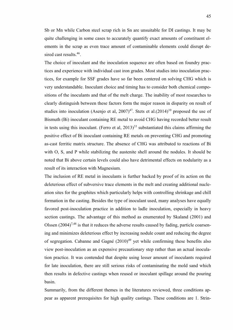
45
Sb or Mn while Carbon steel scrap rich in Sn are unsuitable for DI castings. It may be
quite challenging in some cases to accurately quantify exact amounts of constituent el-
ements in the scrap as even trace amount of contaminable elements could disrupt de-
sired cast results.46.
The choice of inoculant and the inoculation sequence are often based on foundry prac-
tices and experience with individual cast iron grades. Most studies into inoculation prac-
tices, for example for SSF grades have so far been centered on solving CHG which is
very understandable. Inoculant choice and timing has to consider both chemical compo-
sitions of the inoculants and that of the melt charge. The inability of most researches to
clearly distinguish between these factors form the major reason in disparity on result of
studies into inoculation (Asenjo et al, 2007)47. Stets et al.(2014)10 proposed the use of
Bismuth (Bi) inoculant containing RE metal to avoid CHG having recorded better result
in tests using this inoculant. (Ferro et al, 2013)33 substantiated this claims affirming the
positive effect of Bi inoculant containing RE metals on preventing CHG and promoting
as-cast ferritic matrix structure. The absence of CHG was attributed to reactions of Bi
with O, S, and P while stabilizing the austenite shell around the nodules. It should be
noted that Bi above certain levels could also have detrimental effects on nodularity as a
result of its interaction with Magnesium.
The inclusion of RE metal in inoculants is further backed by proof of its action on the
deleterious effect of subversive trace elements in the melt and creating additional nucle-
ation sites for the graphites which particularly helps with controlling shrinkage and chill
formation in the casting. Besides the type of inoculant used, many analyses have equally
favored post-inoculation practice in addition to ladle inoculation, especially in heavy
section castings. The advantage of this method as enumerated by Skaland (2001) and
Olssen (2004)7,48 is that it reduces the adverse results caused by fading, particle coarsen-
ing and minimizes deleterious effect by increasing nodule count and reducing the degree
of segregation. Cabanne and Gagné (2010)49 yet while confirming these benefits also
view post-inoculation as an expensive precautionary step rather than an actual inocula-
tion practice. It was contended that despite using lesser amount of inoculants required
for late inoculation, there are still serious risks of contaminating the mold sand which
then results in defective castings when reused or inoculant spillage around the pouring
basin.
Summarily, from the different themes in the literatures reviewed, three conditions ap-
pear as apparent prerequisites for high quality castings. These conditions are 1. Strin-
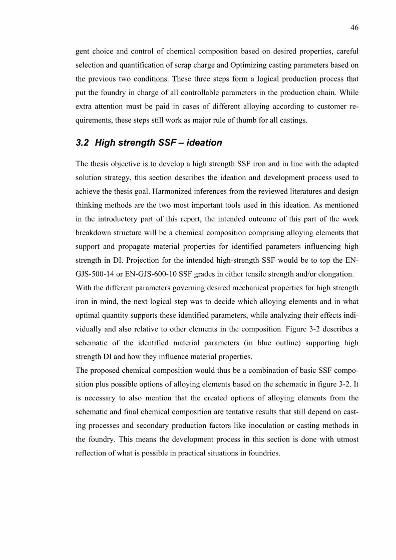
46
gent choice and control of chemical composition based on desired properties, careful
selection and quantification of scrap charge and Optimizing casting parameters based on
the previous two conditions. These three steps form a logical production process that
put the foundry in charge of all controllable parameters in the production chain. While
extra attention must be paid in cases of different alloying according to customer re-
quirements, these steps still work as major rule of thumb for all castings.
3.2 High strength SSF – ideation The thesis objective is to develop a high strength SSF iron and in line with the adapted
solution strategy, this section describes the ideation and development process used to
achieve the thesis goal. Harmonized inferences from the reviewed literatures and design
thinking methods are the two most important tools used in this ideation. As mentioned
in the introductory part of this report, the intended outcome of this part of the work
breakdown structure will be a chemical composition comprising alloying elements that
support and propagate material properties for identified parameters influencing high
strength in DI. Projection for the intended high-strength SSF would be to top the EN-
GJS-500-14 or EN-GJS-600-10 SSF grades in either tensile strength and/or elongation.
With the different parameters governing desired mechanical properties for high strength
iron in mind, the next logical step was to decide which alloying elements and in what
optimal quantity supports these identified parameters, while analyzing their effects indi-
vidually and also relative to other elements in the composition. Figure 3-2 describes a
schematic of the identified material parameters (in blue outline) supporting high
strength DI and how they influence material properties.
The proposed chemical composition would thus be a combination of basic SSF compo-
sition plus possible options of alloying elements based on the schematic in figure 3-2. It
is necessary to also mention that the created options of alloying elements from the
schematic and final chemical composition are tentative results that still depend on cast-
ing processes and secondary production factors like inoculation or casting methods in
the foundry. This means the development process in this section is done with utmost
reflection of what is possible in practical situations in foundries.
47
Figure 3-1. Process steps for developing composition for high strength SSF
Figure 3-2: Material parameters to influence high strength in SSF irons
Expectedly, there is a huge bank of potential alloying elements fitting preliminary re-
quirements for some of these identified parameters for higher strength in DI. To narrow
down the huge number of elements down to more veritable options, more specific de-
tails in the DI specification like its ferritic matrix and grade were matched against prop-
erties of each element. The remainders are then further reduced by considering their
properties and performance against the identified parameters for high strength SSF as
described by step 1 in figure 3-1 showing the process steps leading to the final composi-
tion.
3.2.1 Chemical composition Step 1. – The EN: 1563 standard typically specifies parameters and properties defining
the SSF grade but within the scope of this thesis work, these specifications are loosely
followed to avoid limiting the creative solution space for the intended objective. How-
ever exceptions to this limitation are specifications on Silicon amount and graphite
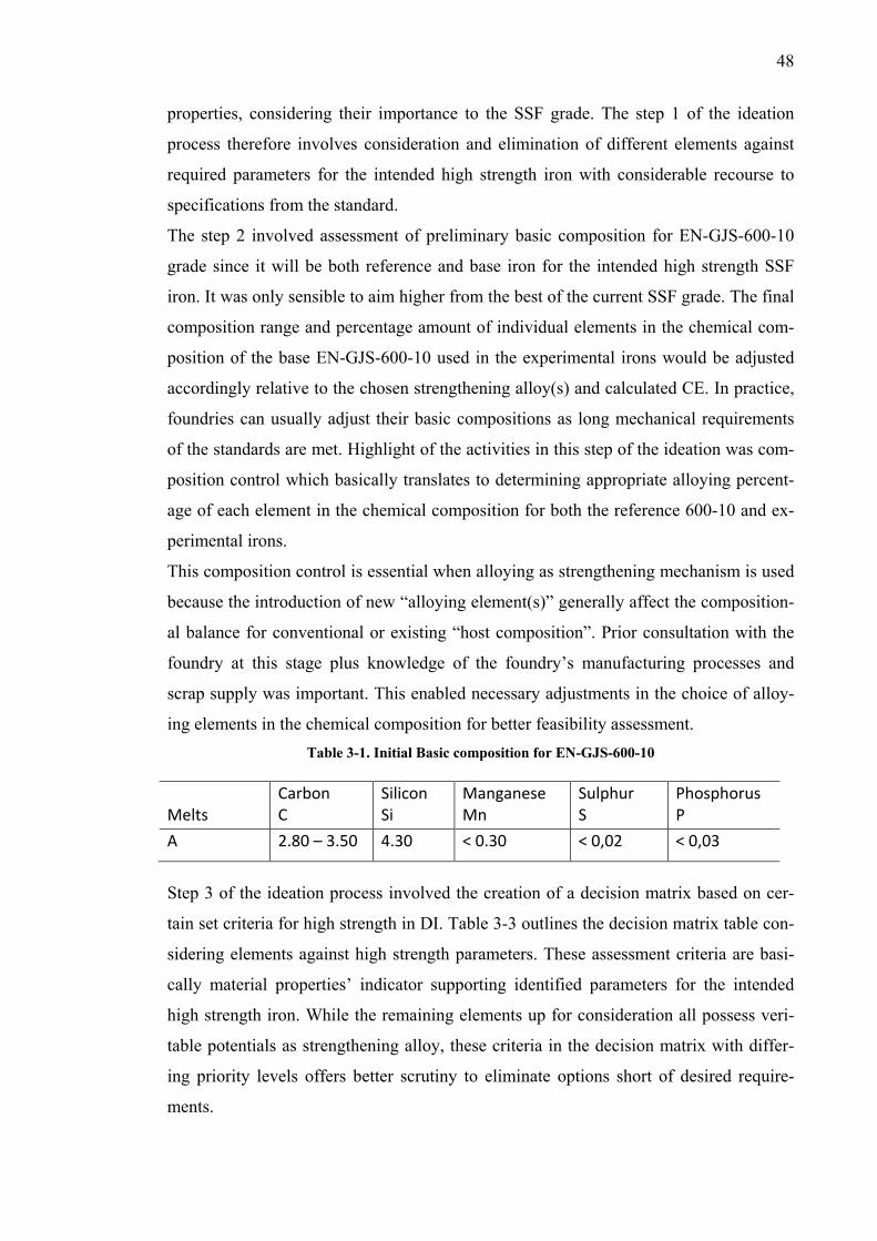
48
properties, considering their importance to the SSF grade. The step 1 of the ideation
process therefore involves consideration and elimination of different elements against
required parameters for the intended high strength iron with considerable recourse to
specifications from the standard.
The step 2 involved assessment of preliminary basic composition for EN-GJS-600-10
grade since it will be both reference and base iron for the intended high strength SSF
iron. It was only sensible to aim higher from the best of the current SSF grade. The final
composition range and percentage amount of individual elements in the chemical com-
position of the base EN-GJS-600-10 used in the experimental irons would be adjusted
accordingly relative to the chosen strengthening alloy(s) and calculated CE. In practice,
foundries can usually adjust their basic compositions as long mechanical requirements
of the standards are met. Highlight of the activities in this step of the ideation was com-
position control which basically translates to determining appropriate alloying percent-
age of each element in the chemical composition for both the reference 600-10 and ex-
perimental irons.
This composition control is essential when alloying as strengthening mechanism is used
because the introduction of new “alloying element(s)” generally affect the composition-
al balance for conventional or existing “host composition”. Prior consultation with the
foundry at this stage plus knowledge of the foundry’s manufacturing processes and
scrap supply was important. This enabled necessary adjustments in the choice of alloy-
ing elements in the chemical composition for better feasibility assessment. Table 3-1. Initial Basic composition for EN-GJS-600-10
Step 3 of the ideation process involved the creation of a decision matrix based on cer-
tain set criteria for high strength in DI. Table 3-3 outlines the decision matrix table con-
sidering elements against high strength parameters. These assessment criteria are basi-
cally material properties’ indicator supporting identified parameters for the intended
high strength iron. While the remaining elements up for consideration all possess veri-
table potentials as strengthening alloy, these criteria in the decision matrix with differ-
ing priority levels offers better scrutiny to eliminate options short of desired require-
ments.
Melts
Carbon C
Silicon Si
Manganese Mn
Sulphur S
Phosphorus P
A 2.80 – 3.50 4.30 < 0.30 < 0,02 < 0,03
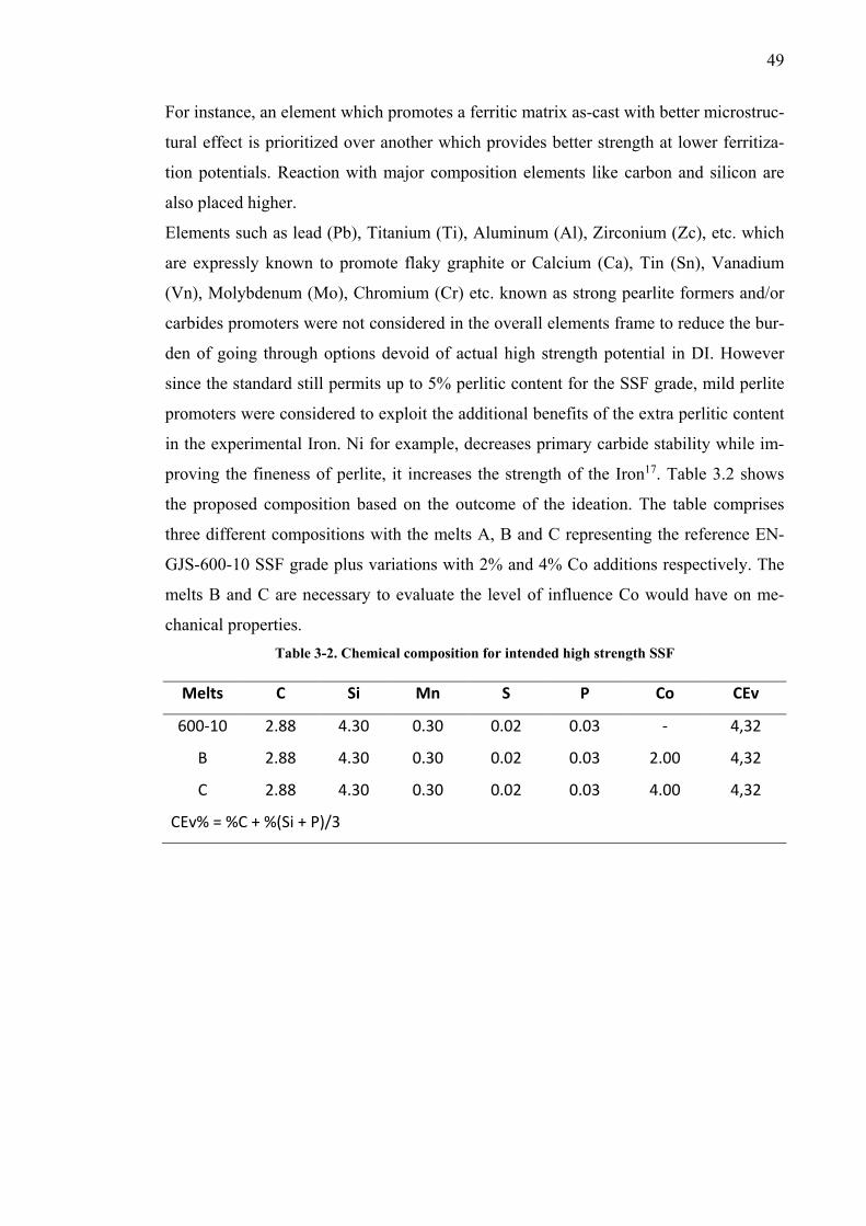
49
For instance, an element which promotes a ferritic matrix as-cast with better microstruc-
tural effect is prioritized over another which provides better strength at lower ferritiza-
tion potentials. Reaction with major composition elements like carbon and silicon are
also placed higher.
Elements such as lead (Pb), Titanium (Ti), Aluminum (Al), Zirconium (Zc), etc. which
are expressly known to promote flaky graphite or Calcium (Ca), Tin (Sn), Vanadium
(Vn), Molybdenum (Mo), Chromium (Cr) etc. known as strong pearlite formers and/or
carbides promoters were not considered in the overall elements frame to reduce the bur-
den of going through options devoid of actual high strength potential in DI. However
since the standard still permits up to 5% perlitic content for the SSF grade, mild perlite
promoters were considered to exploit the additional benefits of the extra perlitic content
in the experimental Iron. Ni for example, decreases primary carbide stability while im-
proving the fineness of perlite, it increases the strength of the Iron17. Table 3.2 shows
the proposed composition based on the outcome of the ideation. The table comprises
three different compositions with the melts A, B and C representing the reference EN-
GJS-600-10 SSF grade plus variations with 2% and 4% Co additions respectively. The
melts B and C are necessary to evaluate the level of influence Co would have on me-
chanical properties. Table 3-2. Chemical composition for intended high strength SSF
Melts C Si Mn S P Co CEv
600-10 2.88 4.30 0.30 0.02 0.03 - 4,32
B 2.88 4.30 0.30 0.02 0.03 2.00 4,32
C 2.88 4.30 0.30 0.02 0.03 4.00 4,32
CEv% = %C + %(Si + P)/3
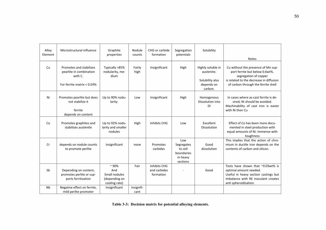
50
Alloy
Element
Microstructural influence
Graphite
properties
Nodule counts
CHG or carbide
formation
Segregation potentials
Solubility
Notes
Cu
Promotes and stabilizes pearlite in combination
with C.
For ferrite matrix < 0.03%
Typically >85% nodularity, me-
dium
Fairly high
Insignificant
High
Highly soluble in
austenite.
Solubility also depends on
carbon.
Cu without the presence of Mn sup-
port ferrite but below 0.6wt%. segregation of copper
is related to the decrease in diffusion of carbon through the ferrite shell
Ni
Promotes pearlite but does
not stabilize it
ferrite depends on content
Up to 90% nodu-
larity.
Low
Insignificant
High
Homogenous
Dissolution into DI
In cases where as-cast ferrite is de-
sired; Ni should be avoided. Machinability of cast iron is easier with Ni then Cu
Co
Promotes graphites and
stabilizes austenite
Up to 92% nodu-larity and smaller
nodules
High
Inhibits CHG
Low
Excellent
Dissolution
Effect of Co has been more docu-mented in steel production with
equal amounts of Ni. Immense with toughness
Cr
depends on nodule counts
to promote perlite
insignificant
none
Promotes carbides
Low Segregates
to cell boundaries
in heavy sections
Good
dissolution
This implies that the action of chro-mium in ductile iron depends on the contents of carbon and silicon.
Sb
Depending on content,
promotes perlite or sup-ports ferritization
~ 90% And
Small nodules (depending on cooling rate)
Fair Inhibits CHG and carbides
formation
-
Good
Tests have shown that ~0.03wt% is optimal amount needed. Useful in heavy section castings but imbalance with RE inoculant creates anti spheroidisation.
Nb Negative effect on ferrite, mild perlite promoter
Insignificant Insignifi-cant
Table 3-3: Decision matrix for potential alloying elements.
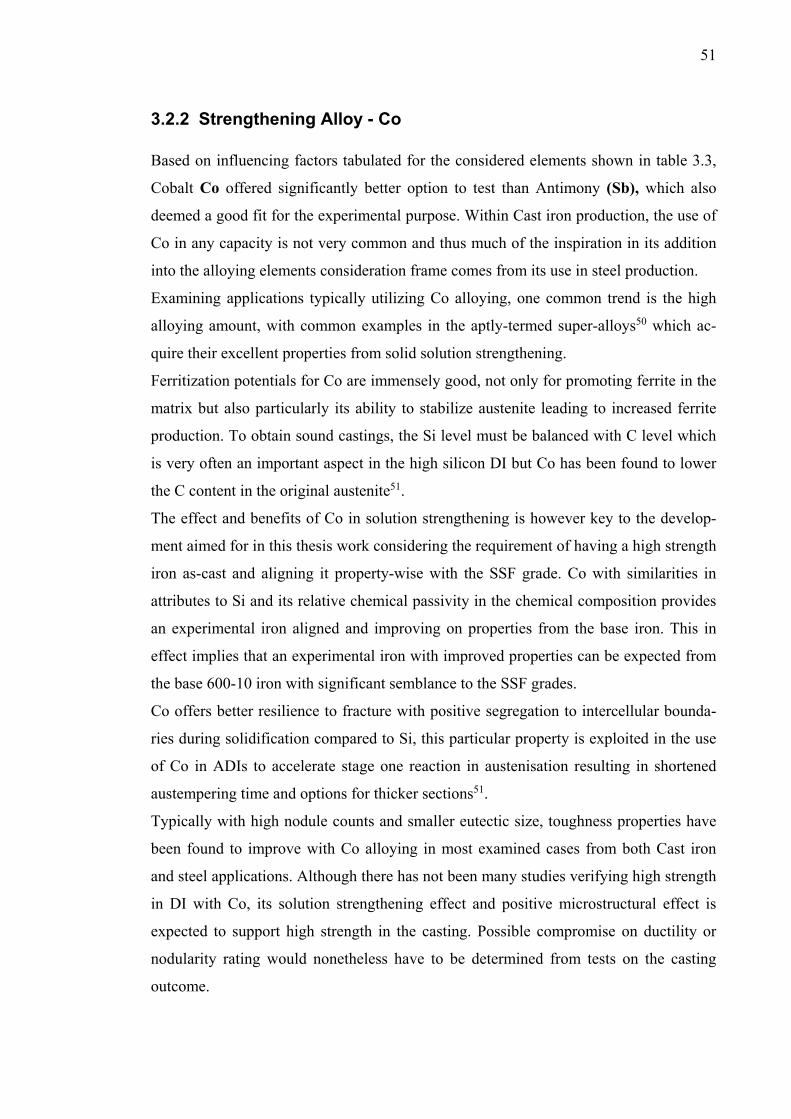
51
3.2.2 Strengthening Alloy - Co Based on influencing factors tabulated for the considered elements shown in table 3.3,
Cobalt Co offered significantly better option to test than Antimony (Sb), which also
deemed a good fit for the experimental purpose. Within Cast iron production, the use of
Co in any capacity is not very common and thus much of the inspiration in its addition
into the alloying elements consideration frame comes from its use in steel production.
Examining applications typically utilizing Co alloying, one common trend is the high
alloying amount, with common examples in the aptly-termed super-alloys50 which ac-
quire their excellent properties from solid solution strengthening.
Ferritization potentials for Co are immensely good, not only for promoting ferrite in the
matrix but also particularly its ability to stabilize austenite leading to increased ferrite
production. To obtain sound castings, the Si level must be balanced with C level which
is very often an important aspect in the high silicon DI but Co has been found to lower
the C content in the original austenite51.
The effect and benefits of Co in solution strengthening is however key to the develop-
ment aimed for in this thesis work considering the requirement of having a high strength
iron as-cast and aligning it property-wise with the SSF grade. Co with similarities in
attributes to Si and its relative chemical passivity in the chemical composition provides
an experimental iron aligned and improving on properties from the base iron. This in
effect implies that an experimental iron with improved properties can be expected from
the base 600-10 iron with significant semblance to the SSF grades.
Co offers better resilience to fracture with positive segregation to intercellular bounda-
ries during solidification compared to Si, this particular property is exploited in the use
of Co in ADIs to accelerate stage one reaction in austenisation resulting in shortened
austempering time and options for thicker sections51.
Typically with high nodule counts and smaller eutectic size, toughness properties have
been found to improve with Co alloying in most examined cases from both Cast iron
and steel applications. Although there has not been many studies verifying high strength
in DI with Co, its solution strengthening effect and positive microstructural effect is
expected to support high strength in the casting. Possible compromise on ductility or
nodularity rating would nonetheless have to be determined from tests on the casting
outcome.
52
3.2.3 Recommendable casting practices While this section does not necessarily try to change conventions about castings or usu-
al practices with different foundries, it aims to give some insight into favorable supple-
mentary practices that could enhance foundry experience while handling SSF castings.
The suggestions given represents combination of different recommendations from nu-
merous researches into how the practical issues in foundries can influence the casting
quality for high silicon ductile irons.
The difference in type of casting has been noted to also have a bearing on the casting
outcome but sand molds are more instrumental in getting a good cast and also a good
option for SSF irons especially in cases where complex castings with large variations in
section size or constrained thin sections. These types of sections are very prone to resid-
ual stresses which can be relieved using sand molds, although usually the occurrence of
residual stresses could be handled with good casting designs. Likewise, premature
shakeout can subsequently induce residual stress in the cast even when sand casting has
been used and also cause hardness variation across the sections52.
The inoculation method used for castings depends on foundry’s experience and also on
type of casting but traditionally, commercial inoculants have been based on ferrosilicon
alloys containing metallic additives such as Calcium, Barium, Strontium, Aluminum,
Zirconium, Rare Earth’s, etc. But with SSF irons, susceptibility to CHG may however
warrant a slight change of direction on conventional inoculants. With restricted availa-
bility of Sulphur and Oxygen in the iron, performance of metallic inoculant additives
would be limited when their effectiveness are restricted by the number of potent nuclea-
tion sites from after inoculation7. Hence the choice of inoculant and application method
should be determined by the quality of scrap metal used and desired properties or ge-
ometry of the casting. For instance, the presence of RE elements in high purity scrap
can be unnecessary and even lead to CHG. Bismuth containing inoculant for both thin
and thick section and Ca-Ce-containing inoculants for thin sections SSF irons have re-
turned good results in recent tests.
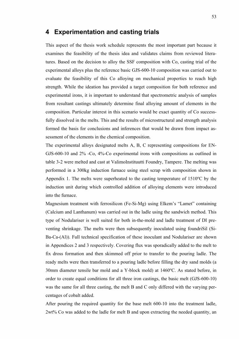
53
4 Experimentation and casting trials This aspect of the thesis work schedule represents the most important part because it
examines the feasibility of the thesis idea and validates claims from reviewed litera-
tures. Based on the decision to alloy the SSF composition with Co, casting trial of the
experimental alloys plus the reference basic GJS-600-10 composition was carried out to
evaluate the feasibility of this Co alloying on mechanical properties to reach high
strength. While the ideation has provided a target composition for both reference and
experimental irons, it is important to understand that spectrometric analysis of samples
from resultant castings ultimately determine final alloying amount of elements in the
composition. Particular interest in this scenario would be exact quantity of Co success-
fully dissolved in the melts. This and the results of microstructural and strength analysis
formed the basis for conclusions and inferences that would be drawn from impact as-
sessment of the elements in the chemical composition.
The experimental alloys designated melts A, B, C representing compositions for EN-
GJS-600-10 and 2% -Co, 4%-Co experimental irons with compositions as outlined in
table 3-2 were melted and cast at ValimoInstituutti Foundry, Tampere. The melting was
performed in a 300kg induction furnace using steel scrap with composition shown in
Appendix 1. The melts were superheated to the casting temperature of 1510oC by the
induction unit during which controlled addition of alloying elements were introduced
into the furnace.
Magnesium treatment with ferrosilicon (Fe-Si-Mg) using Elkem’s “Lamet” containing
(Calcium and Lanthanum) was carried out in the ladle using the sandwich method. This
type of Nodulariser is well suited for both in-the-mold and ladle treatment of DI pre-
venting shrinkage. The melts were then subsequently inoculated using foundriSil (Si-
Ba-Ca-(Al)). Full technical specification of these inoculant and Nodulariser are shown
in Appendices 2 and 3 respectively. Covering flux was sporadically added to the melt to
fix dross formation and then skimmed off prior to transfer to the pouring ladle. The
ready melts were then transferred to a pouring ladle before filling the dry sand molds (a
30mm diameter tensile bar mold and a Y-block mold) at 1460oC. As stated before, in
order to create equal conditions for all three iron castings, the basic melt (GJS-600-10)
was the same for all three casting, the melt B and C only differed with the varying per-
centages of cobalt added.
After pouring the required quantity for the base melt 600-10 into the treatment ladle,
2wt% Co was added to the ladle for melt B and upon extracting the needed quantity, an
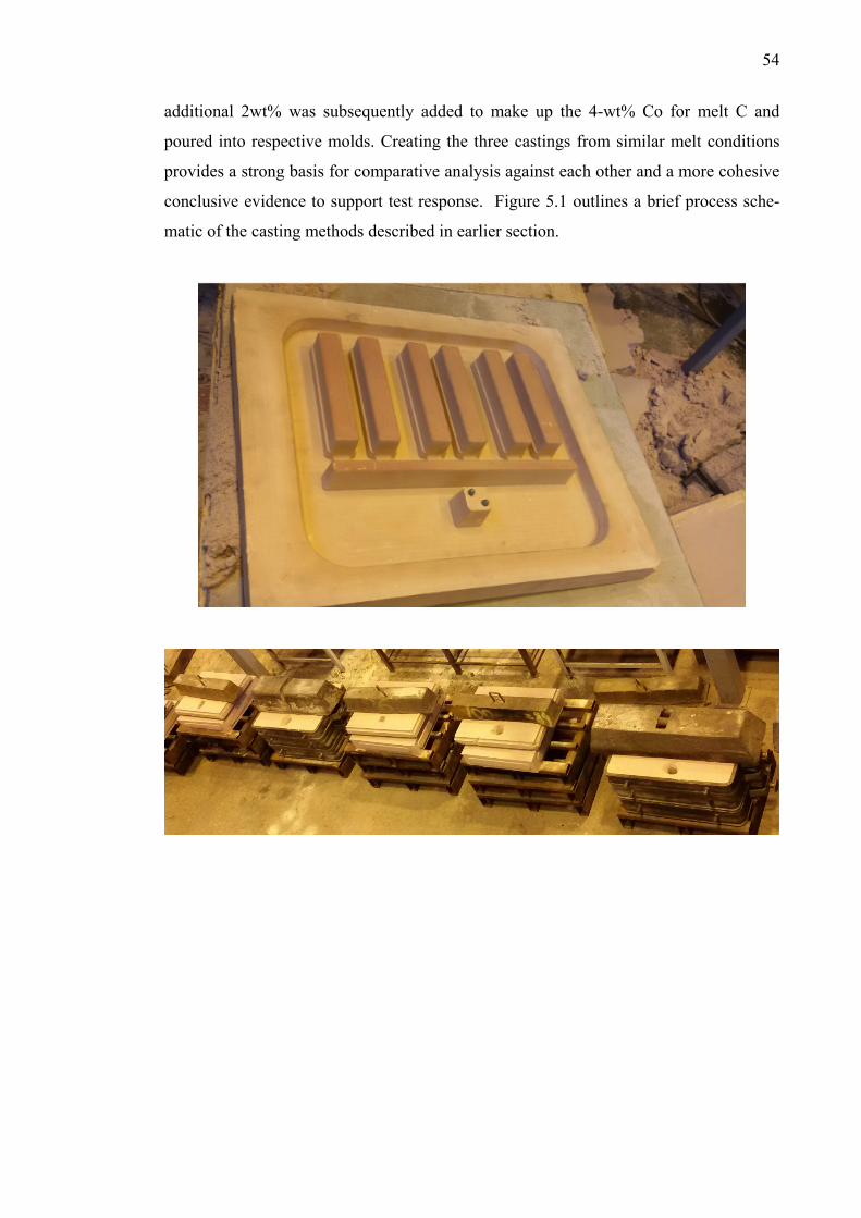
54
additional 2wt% was subsequently added to make up the 4-wt% Co for melt C and
poured into respective molds. Creating the three castings from similar melt conditions
provides a strong basis for comparative analysis against each other and a more cohesive
conclusive evidence to support test response. Figure 5.1 outlines a brief process sche-
matic of the casting methods described in earlier section.
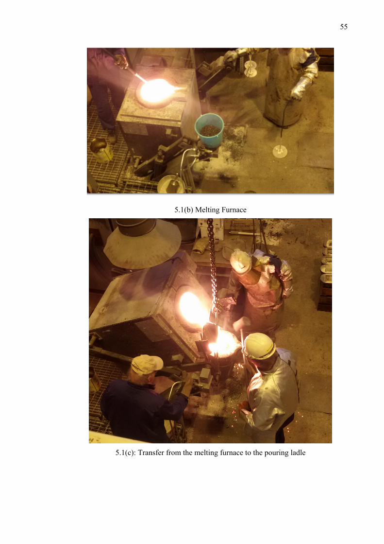
55
5.1(b) Melting Furnace
5.1(c): Transfer from the melting furnace to the pouring ladle
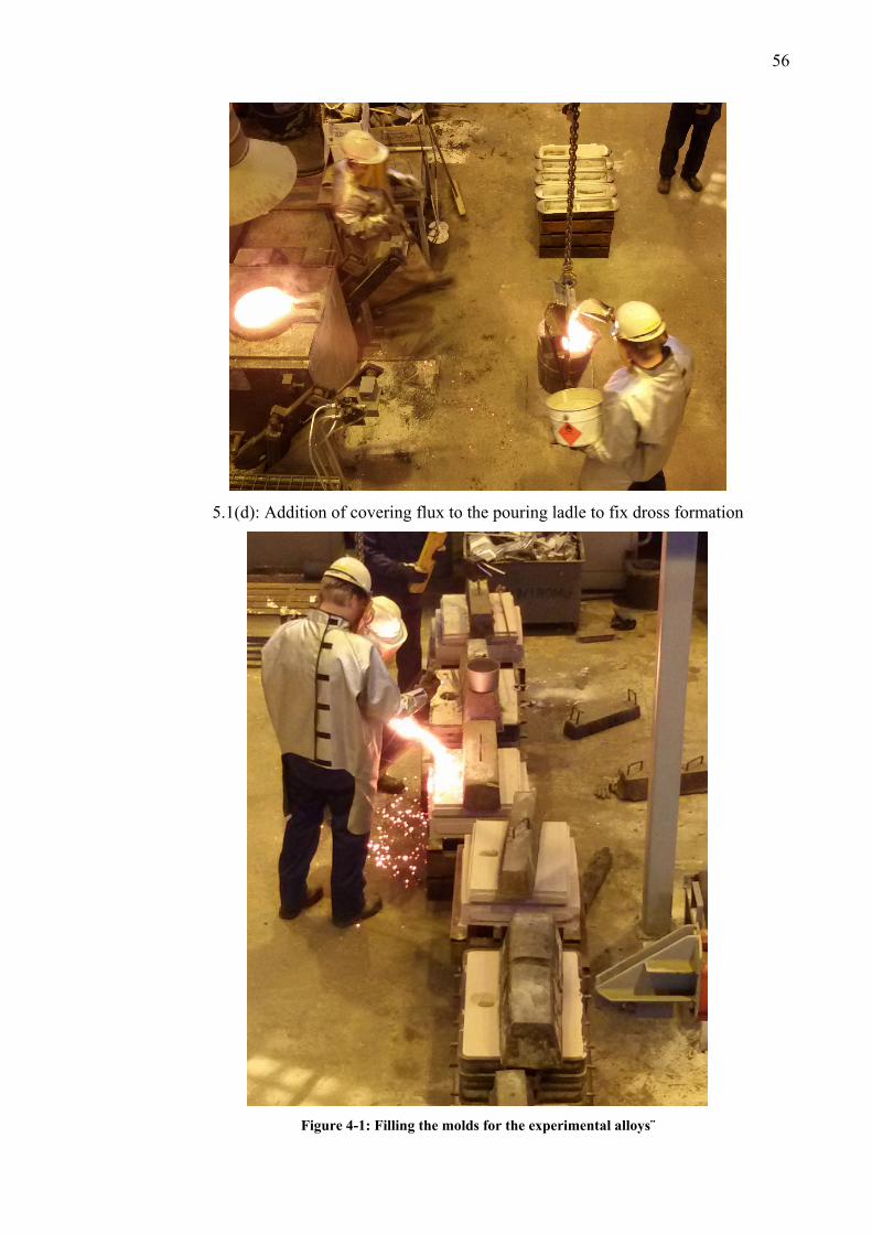
56
5.1(d): Addition of covering flux to the pouring ladle to fix dross formation
Figure 4-1: Filling the molds for the experimental alloys¨
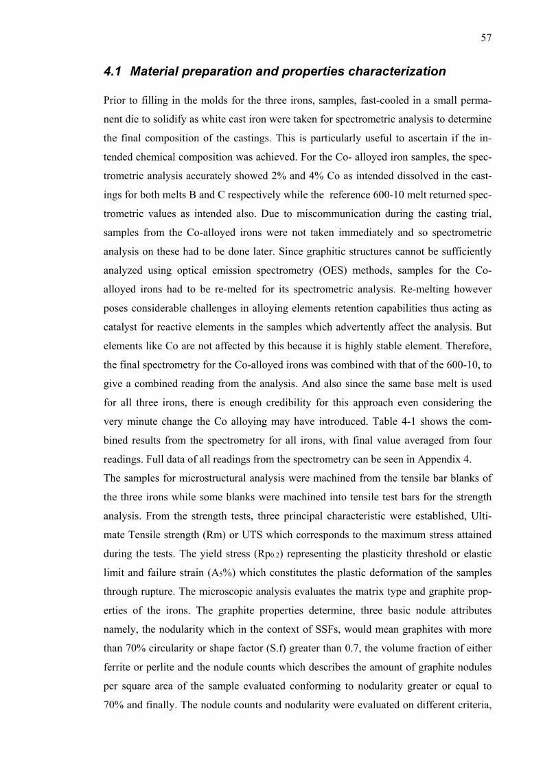
57
4.1 Material preparation and properties characterization Prior to filling in the molds for the three irons, samples, fast-cooled in a small perma-
nent die to solidify as white cast iron were taken for spectrometric analysis to determine
the final composition of the castings. This is particularly useful to ascertain if the in-
tended chemical composition was achieved. For the Co- alloyed iron samples, the spec-
trometric analysis accurately showed 2% and 4% Co as intended dissolved in the cast-
ings for both melts B and C respectively while the reference 600-10 melt returned spec-
trometric values as intended also. Due to miscommunication during the casting trial,
samples from the Co-alloyed irons were not taken immediately and so spectrometric
analysis on these had to be done later. Since graphitic structures cannot be sufficiently
analyzed using optical emission spectrometry (OES) methods, samples for the Co-
alloyed irons had to be re-melted for its spectrometric analysis. Re-melting however
poses considerable challenges in alloying elements retention capabilities thus acting as
catalyst for reactive elements in the samples which advertently affect the analysis. But
elements like Co are not affected by this because it is highly stable element. Therefore,
the final spectrometry for the Co-alloyed irons was combined with that of the 600-10, to
give a combined reading from the analysis. And also since the same base melt is used
for all three irons, there is enough credibility for this approach even considering the
very minute change the Co alloying may have introduced. Table 4-1 shows the com-
bined results from the spectrometry for all irons, with final value averaged from four
readings. Full data of all readings from the spectrometry can be seen in Appendix 4.
The samples for microstructural analysis were machined from the tensile bar blanks of
the three irons while some blanks were machined into tensile test bars for the strength
analysis. From the strength tests, three principal characteristic were established, Ulti-
mate Tensile strength (Rm) or UTS which corresponds to the maximum stress attained
during the tests. The yield stress (Rp0.2) representing the plasticity threshold or elastic
limit and failure strain (A5%) which constitutes the plastic deformation of the samples
through rupture. The microscopic analysis evaluates the matrix type and graphite prop-
erties of the irons. The graphite properties determine, three basic nodule attributes
namely, the nodularity which in the context of SSFs, would mean graphites with more
than 70% circularity or shape factor (S.f) greater than 0.7, the volume fraction of either
ferrite or perlite and the nodule counts which describes the amount of graphite nodules
per square area of the sample evaluated conforming to nodularity greater or equal to
70% and finally. The nodule counts and nodularity were evaluated on different criteria,
58
the former in three categorization of shape factor (S.f) 0.7, 0.9 and perfectly spherical
nodules at unity (1.0), while the latter was evaluated based on “area” and on “nodule
count”. The “area” criterion describes percentage area of spherical nodules in the total
nodule area of the analyzed sample while the nodularity by count expresses percentage
spherical nodules based on nodule counts in the samples. Using these different criteria
for nodularity and nodule counts opens up the possibility of many inferences depending
on assessment perspectives or application.
4.1.1 Microstructural analysis The as-cast samples for the microstructural analysis was sectioned from each of the
three alloys and then prepared using standard metallographic techniques. The samples
were first ground using Silicon carbide paper (SiC-paper) with surface grits from 80 to
1000 and polished with up to 1-micron paste smoothness to get the un-etched surface
microstructures. Further treatment for etching using 2% Nital for the etched micro-
graphs was then performed on the samples. The preliminary grinding and polishing ac-
tivity was necessary to rid the samples of machining scratches or lathe marks for a more
discernable micrograph before and after etching. Optical microscopy (using Nikon
Epiphot 200) for the microstructural analysis was done for normal and 10X magnifica-
tions using similar methods employed in Dasgupta et al53 and Hsu et al17. The matrix
structure was determined through visual inspection against reference images while nod-
ularity and graphite morphology were analyzed using guidelines from the ASTM stand-
ard A-247. All these micro-constituents were then further compared against specifica-
tions for SSF irons provided in EN: 1563 standard. The micrograph analysis were com-
pleted with a scientific image processing open-source software (ImageJ)54 and as de-
fined in the software’s specification, its characterization algorithms for nodule counts
and nodularity ratings follows recommendations from the ASTM E2567-11 stand-
ard55,56. Figure 4.2 shows an overview of the process used in image analysis of the mi-
crographs taken from the samples from this software.
59
Table 4-1: Combined Spectrometry analysis for the three irons
Iron 1 EN-GJS-600-10
C Si Mn P S Cu Al Cr Mo Ni
% % % % % % % % % %
2,77 4,356 0,289 0,019 0,0042 0,025 0,021 0,087 0,0056 0,112
2,746 4,442 0,287 0,018 0,003 0,023 0,019 0,084 0,0049 0,105
2,717 4,398 0,29 0,018 0,0029 0,023 0,019 0,085 0,0062 0,106
2,74 4,36 0,291 0,018 0,0035 0,023 0,019 0,085 0,0055 0,107 Avg 1 2,743 4,389 0,289 0,018 0,003 0,024 0,020 0,085 0,006 0,108
Iron 2 Co-2%
C Si Mn P S Cu Al Cr Mo Ni Co
% % % % % % % % % % %
2,7135 4,381 0,2915 0,0175 0,00285 0,0220 0,0180 0,084 0,0058 0,104 1,951
2,7016 4,3778 0,2924 0,0172 0,00263 0,0214 0,0174 0,0835 0,0059 0,1026 1,91
2,6897 4,3746 0,2933 0,0169 0,00241 0,0208 0,0168 0,083 0,006 0,1012 1,884
2,6778 4,3714 0,2942 0,0166 0,00219 0,0202 0,0162 0,0825 0,0061 0,0998 1,866
Avg 2 2,696 4,376 0,293 0,017 0,003 0,021 0,017 0,083 0,006 0,102 1,903
Iron 3 Co-4%
C Si Mn P S Cu Al Cr Mo Ni Co
% % % % % % % % % % %
2,6659 4,3682 0,2951 0,0163 0,00197 0,0196 0,0156 0,082 0,0062 0,0984 4,114
2,654 4,365 0,296 0,016 0,00175 0,019 0,015 0,0815 0,0063 0,097 4,035
2,6421 4,3618 0,2969 0,0157 0,00153 0,0184 0,0144 0,081 0,0064 0,0956 3,98
2,6302 4,3586 0,2978 0,0154 0,00131 0,0178 0,0138 0,0805 0,0065 0,0942 4,029
Avg 3 2,648 4,363 0,296 0,016 0,002 0,019 0,015 0,081 0,006 0,096 4,040
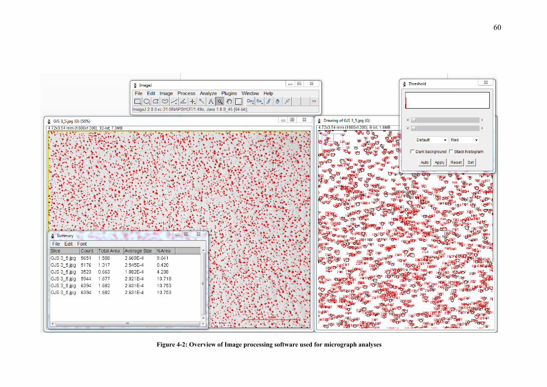
60
Figure 4-2: Overview of Image processing software used for micrograph analyses
61
4.1.2 Static mechanical analysis Strength analysis for the three samples was performed with a 100kN servo-hydraulic
dynamic testing system (MTS 810) shown in figure 4.4. Two sample specimens from
each casting were machined and tested and an average of these values collated. The
analysis procedure follows requirements from the ASTM standard E-8M57 and the test
specimens’ dimensions are shown in figure 4.3. As seen from the figure, the parts of the
bar at opposite ends with larger diameters (12mm) are placed in the wedge grip of the
test machine while the mid-part with the original diameter (10mm) and gauge length
(70mm) represents the core part of the test bar where actual measurements are taken.
The change in gauge length and diameter of this middle part gives the elongation values
at rupture and the ratio of the time-dependent applied loads and the geometric area of
this part provides the tensile stress values. Further estimations of the Ultimate tensile
strength (UTS) and yield strength were then estimated from the stress-strain curves
from data output from the tests. Due to the scope of this thesis, the fracture surface of
specimens were only visually inspected to observe fracture patterns at failure, lending
some evidence to the material behavior in relation to composition or metallurgy when
ruptured.
Figure 4-3: Tensile test Specimen dimensions (mm)
62
Figure 4-4: (a).Images of tensile test bars (b): Tensile testing machine (MTS 810)
Additionally, hardness measurements were done with a Brickers-220 (Gnehm) hardness
tester at a test load 10kg for Vickers hardness. The average of three different readings
on each sample, same used for the microstructural analysis were taken. The three points
were chosen randomly on the samples since the micro-hardness analysis was not ex-
pressly essential for the scope of this thesis. All mechanical tests described in this sec-
tion were implemented at room temperature and in the ambient atmosphere.
63
5 Results
5.1 Microstructure The micrographs of the as-cast samples of GJS-600-10, 2% Co-SSF and 4% Co-SSF
irons in both un-etched and etched conditions are shown in the figures 5-1 and 5.2. The
un-etched microstructure indicates major micro-constituent properties of the iron in-
cluding graphite shapes, size and distribution across the surface. The major difference
with etched samples are clear distinguishable surface showing matrix type, grain
boundaries, and graphite morphology specifically in the etched micrographs of 10X
magnification. A summary of the microstructural properties from the metallographic
analysis of the three samples is presented in Table 5.1. Table 5-1: Microstructure properties of the SSF Iron and Co-alloyed Iron
Sample Nodule
count (Nodule/mm2)
Avg nodule
size µm2
Nodularity %
Graphite %
Ferrite Matrix
%
Perlite (projected)
%
600-10 286 517 86 14.65 ≥ 83.35 < 2
2% Co-iron 352 321 88 11.44 ≥ 84.56 < 4
4% Co- Iron 392 296 88 11.52 ≥ 84.48 < 4
(a) (b) (c)
Figure 5-1(a): Un-etched microstructure of the (a) 600-10, (b) 2%-Co and (c)4%-Co Irons.
64
(a) (b) (c)
Figure 5-2: Etched microstructure of (a) EN-GJS-600-10, (b) 2%-Co and (c) 4%-Co Iron
(a) (b) (c)
Figure 5-3: Etched microstructure of (a) EN-GJS-600-10, (b) 2%-Co and (c) 4%-Co Iron
In analysis of the graphite properties, all nodule sizes (in area) less than 25µm2 were not
considered for evaluation and thus excluded from the results. The shape factor (S.f) or
“spheroidicity” of the nodule is also one of the criteria utilized in analysis. According to
provisions from the ASTM E-2567 standard, nodules with shape factor greater than 0.6
are sufficient for DI characterization and within the scope of SSF iron, the categoriza-
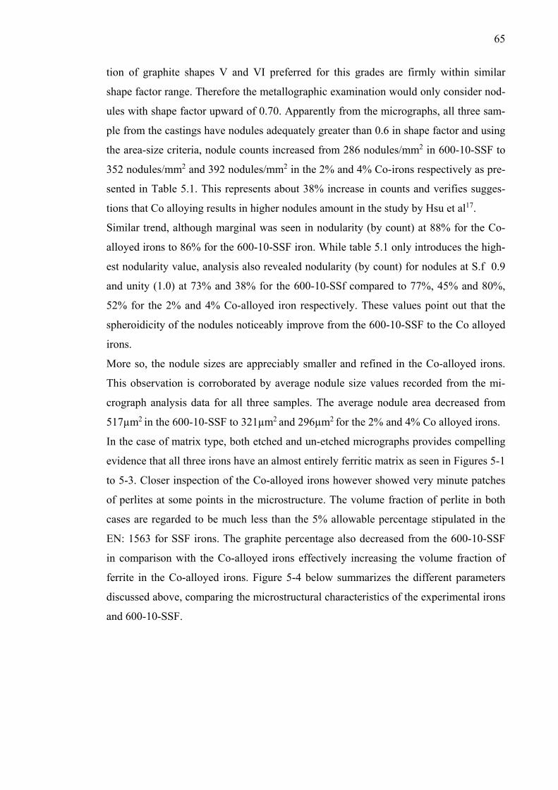
65
tion of graphite shapes V and VI preferred for this grades are firmly within similar
shape factor range. Therefore the metallographic examination would only consider nod-
ules with shape factor upward of 0.70. Apparently from the micrographs, all three sam-
ple from the castings have nodules adequately greater than 0.6 in shape factor and using
the area-size criteria, nodule counts increased from 286 nodules/mm2 in 600-10-SSF to
352 nodules/mm2 and 392 nodules/mm2 in the 2% and 4% Co-irons respectively as pre-
sented in Table 5.1. This represents about 38% increase in counts and verifies sugges-
tions that Co alloying results in higher nodules amount in the study by Hsu et al17.
Similar trend, although marginal was seen in nodularity (by count) at 88% for the Co-
alloyed irons to 86% for the 600-10-SSF iron. While table 5.1 only introduces the high-
est nodularity value, analysis also revealed nodularity (by count) for nodules at S.f 0.9
and unity (1.0) at 73% and 38% for the 600-10-SSf compared to 77%, 45% and 80%,
52% for the 2% and 4% Co-alloyed iron respectively. These values point out that the
spheroidicity of the nodules noticeably improve from the 600-10-SSF to the Co alloyed
irons.
More so, the nodule sizes are appreciably smaller and refined in the Co-alloyed irons.
This observation is corroborated by average nodule size values recorded from the mi-
crograph analysis data for all three samples. The average nodule area decreased from
517µm2 in the 600-10-SSF to 321µm2 and 296µm2 for the 2% and 4% Co alloyed irons.
In the case of matrix type, both etched and un-etched micrographs provides compelling
evidence that all three irons have an almost entirely ferritic matrix as seen in Figures 5-1
to 5-3. Closer inspection of the Co-alloyed irons however showed very minute patches
of perlites at some points in the microstructure. The volume fraction of perlite in both
cases are regarded to be much less than the 5% allowable percentage stipulated in the
EN: 1563 for SSF irons. The graphite percentage also decreased from the 600-10-SSF
in comparison with the Co-alloyed irons effectively increasing the volume fraction of
ferrite in the Co-alloyed irons. Figure 5-4 below summarizes the different parameters
discussed above, comparing the microstructural characteristics of the experimental irons
and 600-10-SSF.
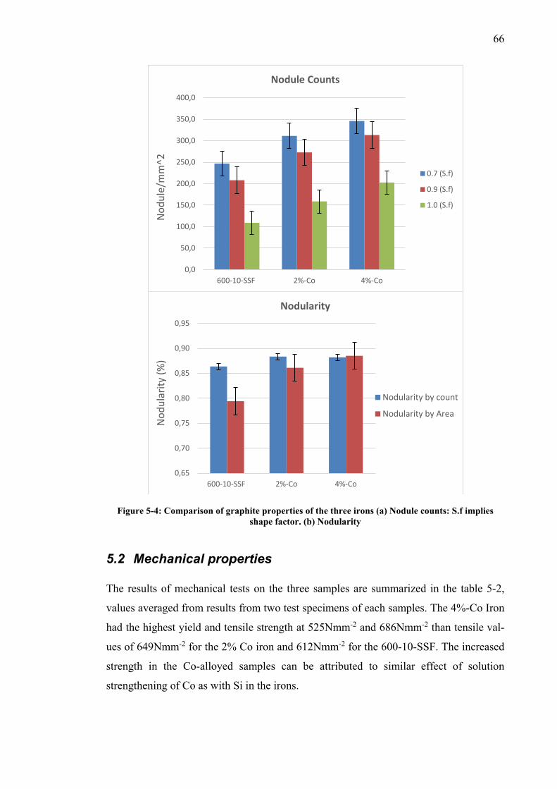
66
Figure 5-4: Comparison of graphite properties of the three irons (a) Nodule counts: S.f implies shape factor. (b) Nodularity
5.2 Mechanical properties The results of mechanical tests on the three samples are summarized in the table 5-2,
values averaged from results from two test specimens of each samples. The 4%-Co Iron
had the highest yield and tensile strength at 525Nmm-2 and 686Nmm-2 than tensile val-
ues of 649Nmm-2 for the 2% Co iron and 612Nmm-2 for the 600-10-SSF. The increased
strength in the Co-alloyed samples can be attributed to similar effect of solution
strengthening of Co as with Si in the irons.
0,0
50,0
100,0
150,0
200,0
250,0
300,0
350,0
400,0
600-10-SSF 2%-Co 4%-Co
Nod
ule/
mm
^2
Nodule Counts
0.7 (S.f)
0.9 (S.f)
1.0 (S.f)
0,65
0,70
0,75
0,80
0,85
0,90
0,95
600-10-SSF 2%-Co 4%-Co
Nod
ular
ity (%
)
Nodularity
Nodularity by count
Nodularity by Area
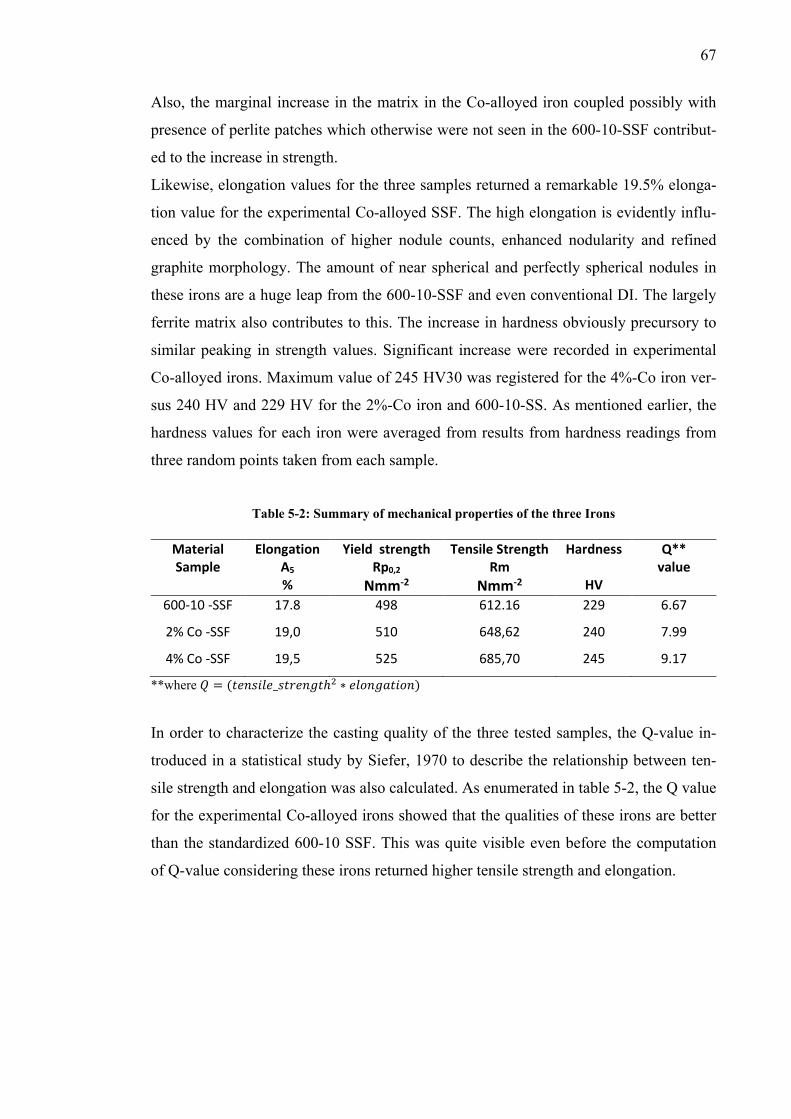
67
Also, the marginal increase in the matrix in the Co-alloyed iron coupled possibly with
presence of perlite patches which otherwise were not seen in the 600-10-SSF contribut-
ed to the increase in strength.
Likewise, elongation values for the three samples returned a remarkable 19.5% elonga-
tion value for the experimental Co-alloyed SSF. The high elongation is evidently influ-
enced by the combination of higher nodule counts, enhanced nodularity and refined
graphite morphology. The amount of near spherical and perfectly spherical nodules in
these irons are a huge leap from the 600-10-SSF and even conventional DI. The largely
ferrite matrix also contributes to this. The increase in hardness obviously precursory to
similar peaking in strength values. Significant increase were recorded in experimental
Co-alloyed irons. Maximum value of 245 HV30 was registered for the 4%-Co iron ver-
sus 240 HV and 229 HV for the 2%-Co iron and 600-10-SS. As mentioned earlier, the
hardness values for each iron were averaged from results from hardness readings from
three random points taken from each sample.
Table 5-2: Summary of mechanical properties of the three Irons
Material Sample
Elongation A5 %
Yield strength Rp0,2
Nmm-2
Tensile Strength Rm
Nmm-2
Hardness
HV
Q** value
600-10 -SSF 17.8 498 612.16 229 6.67
2% Co -SSF 19,0 510 648,62 240 7.99
4% Co -SSF 19,5 525 685,70 245 9.17
**where 𝑄𝑄 = (𝑡𝑡𝑡𝑡𝑡𝑡𝑡𝑡𝑆𝑆𝑡𝑡𝑡𝑡_𝑡𝑡𝑡𝑡𝑠𝑠𝑡𝑡𝑡𝑡𝑠𝑠𝑡𝑡ℎ2 ∗ 𝑡𝑡𝑡𝑡𝑒𝑒𝑡𝑡𝑠𝑠𝑒𝑒𝑡𝑡𝑆𝑆𝑒𝑒𝑡𝑡)
In order to characterize the casting quality of the three tested samples, the Q-value in-
troduced in a statistical study by Siefer, 1970 to describe the relationship between ten-
sile strength and elongation was also calculated. As enumerated in table 5-2, the Q value
for the experimental Co-alloyed irons showed that the qualities of these irons are better
than the standardized 600-10 SSF. This was quite visible even before the computation
of Q-value considering these irons returned higher tensile strength and elongation.
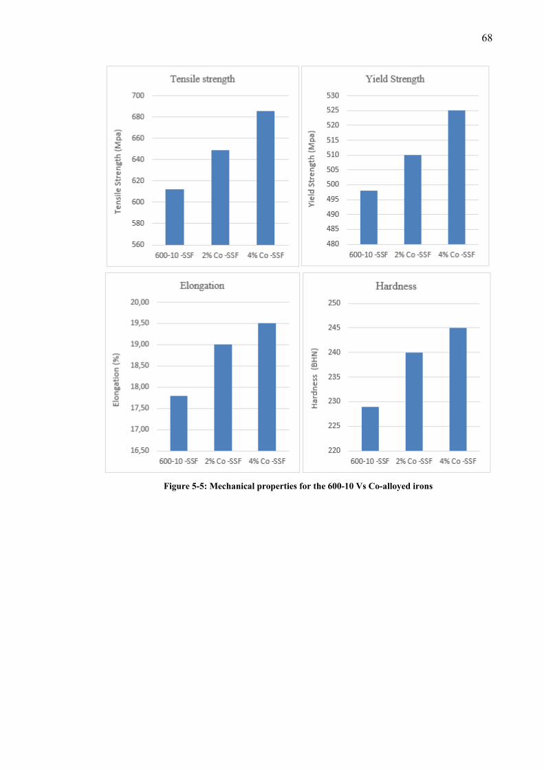
68
Figure 5-5: Mechanical properties for the 600-10 Vs Co-alloyed irons
69
6 Discussion of Results
6.1 Graphite properties Improvement in graphite properties and strength recorded for the experimental Co-
alloyed irons summed up the most significant effect of Co in the chemical composition.
The graphite properties provides an explanation for the elongation results and casting
quality. As expected, results from the optical microscopy analysis from all three irons,
the GJS-600-10 and Co-alloyed experimental SSFs shows a dominant ferrite matrix
with no obvious signs of graphite degeneracy thus confirms similarity in both Si and Co
as strong ferrite promoters. The perlite content in the matrix is estimated to be less than
the allowable 5% of total micro constituent in the iron as specified in the EN 1563 for
SSF irons. Despite the known effect of Si as a strong graphitizer and ferrite promoter,
similar stronger action for Co is quite apparent from the microstructural results showing
increased nodule counts, smaller graphite size and refined spherical nodules in agree-
ment with conclusions from studies into Co-alloying in DI by Hsu et al, 2007 and Modl,
197258.
1. The higher nodule count, improved morphology and enhanced nodularity
accounts for the better elongation seen in the experimental Co-alloyed irons
compared to the standardized 600-10-SSF. The gains in nodule counts and
nodularity in the experimental irons can be credited to the austenite stabilizing
effect of Co in the irons. This property enables better carbon diffusion in an
increased nucleation sites for eutectic graphites in the microstructure. In current
SSF grades, the high Si have been linked to influence aggregation of CHG due
to large formation of heterogeneous nucleation sites and drop in melting point of
austenitic shells. The stability provided by the addition of Co in the iron
improves impending lattice de-registry with austenite found in oxidized iron
containing numerous Si oxide particles. Therefore, the better nodularity in the
Co-alloyed irons minimized notch effects from the nodules thereby increasing
strength needed to propagate dislocation movement.
2. The microstructural assessment also revealed improved and refined graphite
morphology in the experimental Co irons. The average nodule size decreased
from 517µm2 for the reference 600-10 to 321µm2 and 296µm2 for the 2% and
4% Co-alloyed experimental SSF respectively. Such because nodularisation
70
efficiency is higher in the Co-alloyed irons arising from a shift in levels of
heterogeneous nucleation sites also due to stabilized austenite. The choice of
inoculants containing Ca, Ba along with ferrosilicon also played a vital role in
microstructural properties. Inoculants present and solidification condition
determine the nucleation temperature and the eutectic cell counts. They also
influence the solidification condition when growth starts
3. Although, microstructural evaluation did include a fractograph analysis to
examine failure pattern of the irons or dispersive extent of Co or other alloying
element in the composition. Visual inspection of the fractured samples and
speculative inferences from using similar base composition for all three irons
suggests that potential segregation from chill carbides, Si or Co is kept to a very
minimum in these castings. The 600-10 iron casting meeting its mechanical
properties requirements as designated in the standard also supports this
conjecture. Nevertheless, it is noteworthy that detailed fracture analysis is
necessary to definitively validate this conclusion.
6.2 Mechanical properties The mechanical properties of the three irons samples are consistent with the composi-
tion and microstructure of the irons. While ferritization by Si is well documented and
expected for the 600-10 iron, similar results for the Co alloyed irons shows that Co also
promotes ferrite. Co influences the diffusion of carbon through the ferrite shell, moving
the knee of a transformation diagram to lower time interval stabilizing the ferrite matrix
and resulting in reduced perlite formation.
4. From the results of the Co-alloyed irons, the better UTS and yield strength can
be explained through the solution strengthening effect of Co on the matrix.
While exact volume fraction of ferrite in the microstructure cannot be precisely
quantified with metallographic analysis tool used, hardness increase corresponds
to the improvements seen in strength for the Co-alloyed irons indicating matrix
homogeneity. Co in addition to improving nodule formation5,17 also influence
more ferrite formation through its austenite stabilization capabilities within
eutectic graphites cells. While Silicon possess similar influences on the iron, the
difference between both is the sensitivity of Si to forming CHG above certain
amount in the composition if improperly managed.

71
5. It was also found that the finer and homogenous microstructure was influenced
by the increased nodule counts which provided more nucleation sites for ferrite
growth and reduction of segregation potential for deleterious elements in the
melt59 which are often responsible for the presence of intercellular carbides,
pearlite and degenerate graphite.
Owing to a refined matrix, eutectic cell carbides, perlite or degenerated graphites cannot
be precipitated making dislocation movement difficult to propagate. These different
factors relating to the matrix however possess different effects on mechanical proper-
ties.
6. Nodule count influences the pearlite content in as-cast DI. Increasing the nodule
count decreases pearlite which then affects strength and increases elongation.
Improved nodule counts, through the reduction of chill carbides, segregation
carbides, and carbides associated with "inverse chill", improves ductility and
from a production point, machinability of the casting.
7. The increased nodule counts in the Co-alloyed irons and efficient nodularisation
again owing to austenite stability by Co alloying influenced graphite size and
shape. Using deductive inferences relating this outcome to results from similar
studies in Co-alloying, fatigue and fracture properties in the experimental Co
irons are expected to be improved.
8. The overall quality measured with the Q-value indicate that increased nodule
counts is an important feature and highlight of the experimental Co irons in this
thesis work. As shown in figure 6-1, the effect of the hiked counts in the Co-
alloyed irons contributed to both elongation and strength of the iron which is
evident on overall casting quality.
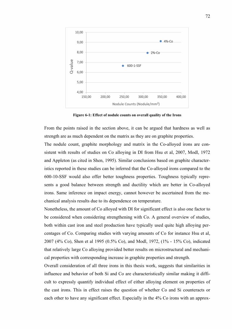
72
Figure 6-1: Effect of nodule counts on overall quality of the Irons
From the points raised in the section above, it can be argued that hardness as well as
strength are as much dependent on the matrix as they are on graphite properties.
The nodule count, graphite morphology and matrix in the Co-alloyed irons are con-
sistent with results of studies on Co alloying in DI from Hsu et al, 2007, Modl, 1972
and Appleton (as cited in Shen, 1995). Similar conclusions based on graphite character-
istics reported in these studies can be inferred that the Co-alloyed irons compared to the
600-10-SSF would also offer better toughness properties. Toughness typically repre-
sents a good balance between strength and ductility which are better in Co-alloyed
irons. Same inference on impact energy, cannot however be ascertained from the me-
chanical analysis results due to its dependence on temperature.
Nonetheless, the amount of Co alloyed with DI for significant effect is also one factor to
be considered when considering strengthening with Co. A general overview of studies,
both within cast iron and steel production have typically used quite high alloying per-
centages of Co. Comparing studies with varying amounts of Co for instance Hsu et al,
2007 (4% Co), Shen et al 1995 (0.5% Co), and Modl, 1972, (1% - 15% Co), indicated
that relatively large Co alloying provided better results on microstructural and mechani-
cal properties with corresponding increase in graphite properties and strength.
Overall consideration of all three irons in this thesis work, suggests that similarities in
influence and behavior of both Si and Co are characteristically similar making it diffi-
cult to expressly quantify individual effect of either alloying element on properties of
the cast irons. This in effect raises the question of whether Co and Si counteracts or
each other to have any significant effect. Especially in the 4% Co irons with an approx-
73
imately equal amount of Si in the irons. It can of course be suggested that increasing
Co can produce further strength increase and elongation for the irons going by a linear
forecast of the data points from the strength testing. However, data points from the three
irons tested in this thesis work, are statistically insufficient to project on what form or
type of increment will be derived for irons with increasing amounts of Co.
Within the body of studies relating to strengthening SSF irons, this thesis work is the
first of such research endeavors, the result of which cannot be conclusively related to all
grades within the SSF family. There is not enough evidence from this work alone to
prove either the EN-GJS-500-14 or 450-18 would behave similarly. In similar perspec-
tive, although there is considerable difference in mechanical properties between the 2%
and 4% Co-alloyed 600-10, it is still a bit difficult to clearly claim or understand if the
strength increase for instance between these two irons will either be continuously pro-
portional to Co percentage increase or plateau out as some alloying quantity. It might
also be the case that a 2% difference in alloying content is not sufficient enough to visu-
alize this. Hence the need for a more detailed work utilizing differing amount of Co.
Additionally, knowledge of Co alloying especially in DI casting is generally lacking
which and as such, considerable independent assessment of its properties in combina-
tion with traditional DI composition should be adequately understood before reincorpo-
ration into SSF use.
6.3 Recommendation for further studies Generally, while the results derived from tests satisfies the intended objectives of the
thesis work, there are still important questions relating to the use of cobalt alloying that
remained unanswered. And also some due to inconclusive evidence based on the extent
of the implemented tests within the scope of this work.
Although, there appears to be remarkable difference in properties between the 600-10
SSF and Co-alloyed iron, further exploratory study of Co in SSFs with Si level above
the identified critical percentage of 4.3wt% would be a good insight and stronger valida-
tion of the effect of Co-alloying in creating higher strength SSF. With results from such
studies, the exact role of Co in actual quantifiable measures in this regard can be ade-
quately verified. More so, the issue of CHG is still not ideally addressed within the con-
text of the results and casting trials. Further casting trials with heavier casting sections
traditionally prone to CHG should be implemented to examine the effect of Co. Defini-
tive assessment and tests on toughness, impact strength and fracture analysis would be a
74
useful supplement to the tests reported here in the report. It gives more credence and
fuller characterization to the properties of the experimental alloys. In addition, SEM
analysis and the material behavior at elevated temperatures would also be application to
the attribute portfolio of the Co-alloyed irons.
75
Bibliography
1. Standard E. NORM FprEN 1563:2011, founding - spheroidal graphite cast irons.
EUROPEAN COMMITTEE FOR STANDARDIZATION. 2011;ICS 77.080.10.
2. Duit B. EN 1563: New generation ductile irons ( solid solution strengthened ductile
irons ). . 2012.
3. Alhussein a, Risbet M, Bastien a, Chobaut JP, Balloy D, Favergeon J. Influence of
silicon and addition elements on the mechanical behavior of ferritic ductile cast
iron. Materials Science and Engineering: A. 2014;605:222-228.
4. Wiley J. Fundamentals of materials science and engineering an interactive. .
file:///C:/Users/pachoskie/Desktop/HiSi/CI/Callister - Fundamentals of Materials
Science and Engineering 5e HQ.pdf. Accessed 2/5/2015 5:12:34 AM.
5. RTZ Iron and Titanium America. A design engineer's digest of ductile iron - the cast
iron of the past, present and future. Sorel Metal. ;Ductile iron marketing group di-
gests(8th Edition).
6. Olsson A. Fatigue strength of truck components in cast iron. . 2011.
7. Elkem foundry products. Cast iron inoculation. the technology of graphite shape con-
trol. Products market brochure. 2012;1(1):1.
8. Larker R, Ab I, Vindeln S-. Solution strengthened ferritic ductile iron ISO 1083 / JS /
500-10 provides superior consistent properties in hydraulic rotators. . 2009.
9. Prihti T. Wear behaviour of ductile irons in continuous sliding motion. [Msc]. Tam-
pere university of technology; 2011.
10. Stets W, Lablich H, Giebereitechnik I, Gassner G, Schumacher P. Solution strength-
ened ferritic ductile cast irons- properties, production and application. . 2013;18(2).
11. Componenta Dokum A.S. EN1563 - new generation ductile irons. 7th International
Ankiros Foundry congress. 2014;1(1):1-55.
76
12. Rousku M. CASE : Uudet valuraudat valun kayton seminaari 2010. Componenta
Oy. 2010.
13. Lin H, Lui T, Chen L. Effect of silicon content on intergranular embrittlement of
ferritic spheroidal graphite cast iron suffered from cyclic heating. Materials Trans-
actions. 2003;44(1):173-180.
14. Källbom, R. K Hamberg, L-E Björkegren. Chunky graphite in ductile iron castings.
World foundry conference. 2006.
15. Källbom R, Hamberg K, Wessén M, Björkegren L-. On the solidification se-
quence of ductile iron castings containing chunky graphite. Materials Science and
Engineering: A. 2005;413-414:346-351.
16. Gonzaga RA. Influence of ferrite and pearlite content on mechanical properties of
ductile cast irons. Materials Science and Engineering: A. 2013;567:1-8.
17. Hsu C, Chen M, Hu C. Microstructure and mechanical properties of 4% cobalt and
nickel alloyed ductile irons. Materials Science and Engineering: A. 2007;444(1-
2):339-346.
18. Björkegren LE, Hamberg K. 2003 keith millis symposium on ductile cast iron sili-
con alloyed ductile iron with excellent ductility and machinability 2003 keith millis
symposium on ductile cast iron. . 2003.
19. Herfurth VONK, Gorski R, Beute K, Marcus UND. Gusswerkstoff fUr den maschi-
nenbau mit hoherer festigkeit und bruchdehnung bei sehr homogener hartevertei-
lung. . 2011.
20. Serrallach J, Lacaze J, Sertucha J, Suárez R, Monzón A. Effect of selected alloy-
ing elements on mechanical properties of pearlitic nodular cast irons. Key Eng Mat.
2010;457:361-366.
21. Gonzaga RA, Carrasquilla JF. Influence of an appropriate balance of the alloying
elements on microstructure and on mechanical properties of nodular cast iron. J
Mater Process Technol. 2005;162-163:293-297.
77
22. Jovanović MT, Lukić B, Mišković Z, Bobić I, Cvijović I, Dimčić B. Processing and
some applications of nickel, cobalt and titanium-based alloys. .
23. Riposan I, Chisamera M, Stan S. Influencing factors on as-cast and heat treated 400-
18 ductile iron grade characteristics. . 2007;4(4):6-9.
24. Muhmond HM, Fredriksson H. Graphite growth morphologies in cast iron. Mater
Sci Forum. 2014;790-791:458 <last_page> 463.
25. Skaland T. Ductile iron shrinkage control through graphite nucleation and growth.
International Journal of Cast Metals Research. 2003;16(1):11-16.
26. Kallbom, R., Hamberg, K., Bjorkegren, L. E. Chunky graphite formation and influ-
ence on mechanichal properties in ductile cast iron. In Component Design by Cast-
ings, VTT Symposium. 2005(237.).
27. I. Riposan, M. Chisamera, R. Kelley,M. Barstow, R. L. Naro. Magnesium-sulfur
relationships in ductile and compacted graphite cast irons as influenced by late sul-
fur additions. AFS Transactions. 2003;111(03-093):869-883.
28. Skaland T. A new approach to ductile iron inoculation. . 2001:1-12.
29. Nakae, H., Jung, S., Kitazawa, T. Eutectic solidification mode of spheroidal graphite
cast iron and graphitization. Research & Development. 2007.
30. Larrañaga P, Asenjo I, Sertucha J, Suarez R, Ferrer I, Lacaze J. Effect of antimony
and cerium on the formation of chunky graphite during solidification of heavy-
section castings of near-eutectic spheroidal graphite irons. Metallurgical and Mate-
rials Transactions A. 2009;40(3):654- 661.
31. Larrañaga P, Asenjo I, Sertucha J, Suárez R, Ferrer I, Lacaze J. Effect of antimony
on the eutectic reaction of heavy section spheroidal graphite castings. International
Journal of Cast Metals Research. 2009;22(1-4):192 - 195.
32. Nakae H, Fukami M, Kitazawa T, Zou Y. Influence of si, ce, sb and sn on chunky
graphite formation. .
78
33. Ferro P, Fabrizi a, Cervo R, Carollo C. Effect of inoculant containing rare earth
metals and bismuth on microstructure and mechanical properties of heavy-section
near-eutectic ductile iron castings. J Mater Process Technol. 2013;213(9):1601-
1608.
34. Zhe L, Weiping C, Yu D. Influence of cooling rate and antimony addition content
on graphite morphology and mechanical properties of a ductile iron. Research &
Development. 2012.
35. Diao XG, Ning ZL, Cao FY, Ren SZ, Sun JF. Microstructure evolution of heavy
section ductile iron. Advanced Materials Research. 2010;97-101:1020 <last_page>
1023.
36. Diao XG, Ning ZL, Cao FY, Ren SZ, Sun JF. Microstructure evolution of heavy
section ductile iron. Advanced Materials Research. 2010;97-101:1020 <last_page>
1023.
37. Song L, Guo E, Wang L, Liu D. Effects of silicon on mechanical properties and
fracture toughness of heavy-section ductile cast iron. Metals. 2015;5(1):150
<last_page> 161.
38. Shinde VD, Ravi B, Narasimhan K. Solidification behaviour and mechanical prop-
erties of ductile iron castings with varying thickness. International Journal of Cast
Metals Research. 2012;25(6):364 <last_page> 373.
39. ZOU Y. Influence of alloying elements and melting conditions on graphite mor-
phology and matrix in fe-C and ni-C alloys. [Doctoral dissertation]. Wased Univer-
sity; 2012.
40. Cho GS, Choe KH, Lee KW, Ikenaga A. Effects of alloying elements on the micro-
structures and mechanical properties of heavy section ductile cast iron. .
2007;23(1):97-101.
41. Shen P, Harris SJ, Noble B. Influence of small vanadiul11and cobalt additions on
microstructure and properties of ductile iron. . 1995;11.
79
42. Ramadan M, Fathy N, Hafez KM. Effect of graphite nodularity on mechanical prop-
erties of ductile iron for waterworks fittings and accessories. . :1-5.
43. Engineering F. Effect of small additions of vanadium and niobium on structure and
mechanical properties of ductile iron. . 2007;7(1):89-92.
44. Nylén T. NIOBIUM IN CAST IRON. .
45. Solis E, Hernandez B. Effect of niobium in medium alloyed ductile cast irons. .
2003;16(5):3-9.
46. Hiratsuka S, Horie H, Kowata T, Koike K, Shimizu K. Influence of steel scrap on
microstructure and mechanical properties of spheroidal graphite cast iron. Materi-
als Transactions. 2003;44(7):1419-1424.
47. Asenjo I, Larranaga P, Sertucha J, et al. Effect of mould inoculation on formation of
chunky graphite in heavy section spheroidal graphite cast iron parts. International
Journal of Cast Metals Research. 2007;20(6):319 <last_page> 324.
48. Olsen SO, Skaland T, Hartung C. Inoculation of grey and ductile iron A comparison
of nucleation sites and some practical advises. .
49. Cabanne, P., Gagné, M. INOCULATION OF DUCTILE IRON- WHY AND
WHEN? Suggestions for Ductile Iron Production. 2010;Sorelmetal Technical Ser-
vices(115):1.
50. Reed R. The superalloys: Fundamentals and applications. Cambridge University
Press.
51. S Yazdani HB,R Elliott. The influence of cobalt on the austempering reaction in
ductile cast iron. International journal of cast metals research. 2001;13:317-326.
52. Davis JR. ASM specialty handbook: Cast irons. ASM international; 1996.
53. Dasgupta RK, Mondal DK, Chakrabarti AK, Ganguli AC. Microstructure and me-
chanical properties of as-cast ductile irons alloyed with manganese and copper.
Journal of Materials Engineering and Performance. 2011;21(8):1728-1736.
80
54. Kevin E. imageJ is an open source image processing program designed for scientific
multidimensional image. http://imagej.net/Welcome. Accessed 5/11/2015, 2015.
55. Prakash P, Mytri V, Hiremath P. Digital microstructure analysis system for testing
and quantifying the ductile cast iron. International Journal of Computer Applica-
tions. 2011;19.
56. ASTM E2567 - 11 standard test method for determining nodularity and nodule
count in ductile iron using image analysis.
http://www.astm.org/DATABASE.CART/HISTORICAL/E2567-11.htm. Accessed
5/11/2015, 2015.
57. ASTM E8 / E8M - 13a standard test methods for tension testing of metallic materi-
als. http://www.astm.org/Standards/E8.htm. Accessed 5/11/2015, 2015.
58. Modl EK, inventor; Sulzer Ag, assignee. Compacted graphite cast irons in the iron-
carbon-aluminum system. 1972.
59. Bockus S, Zaldarys G. Evaluation of producing technique factors affecting the ma-
trix microstructure of as-cast ductile iron castings. Metalurgija. 2011;50(1):9-12.

81
7 Appendices Appendix 1. Scrap composition and melt charge. 1 page. Appendix 2. Inoculant Specification – FoundriSil. 2pages Appendix 3. Nodulariser specification – Lamet. I page Appendix 4. Spectrometric analysis -2 pages. Appendix 5. Stress- strain curves and Rp0.2 estimation curves. 2 pages

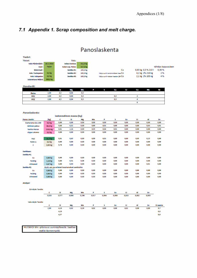
Appendices (1/8)
7.1 Appendix 1. Scrap composition and melt charge.
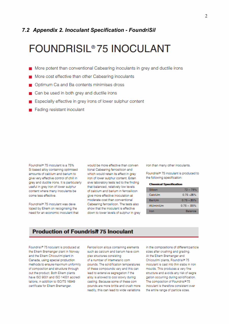
2
7.2 Appendix 2. Inoculant Specification - FoundriSil
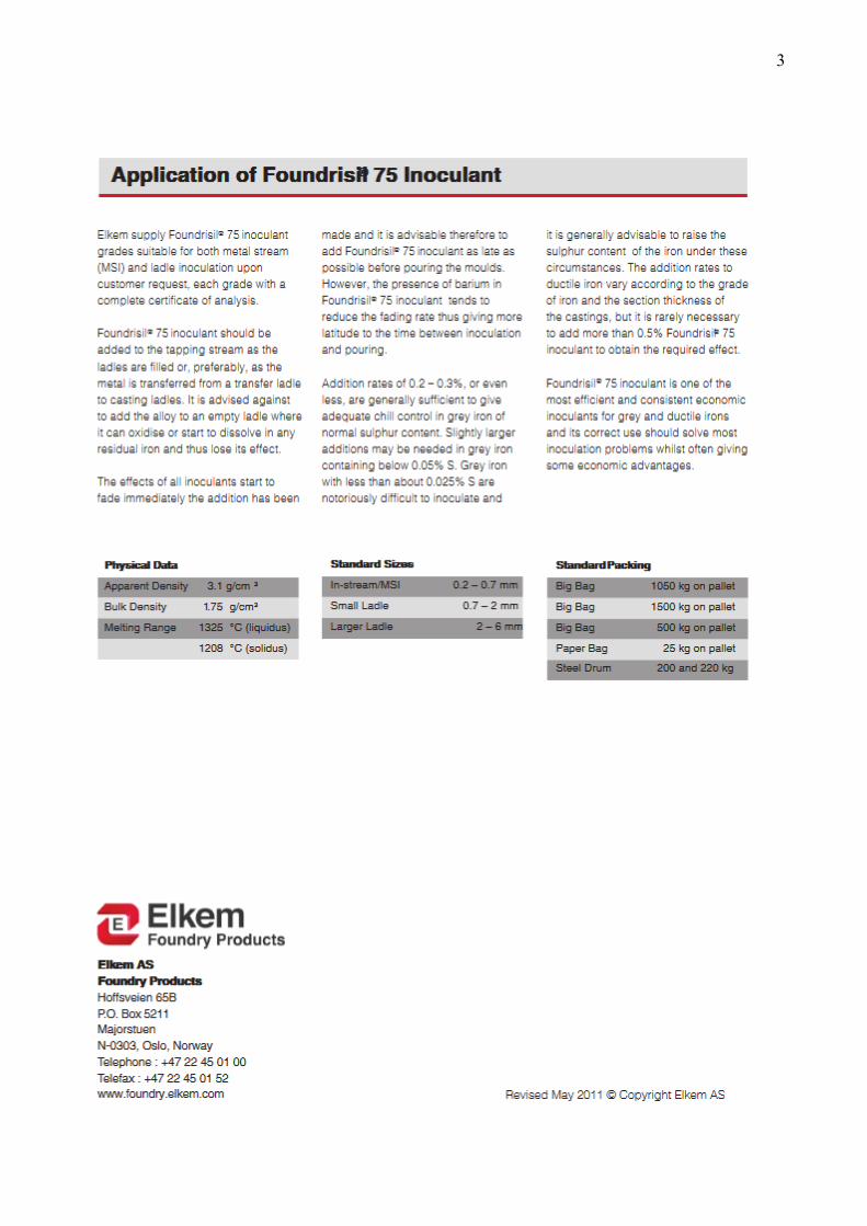
3
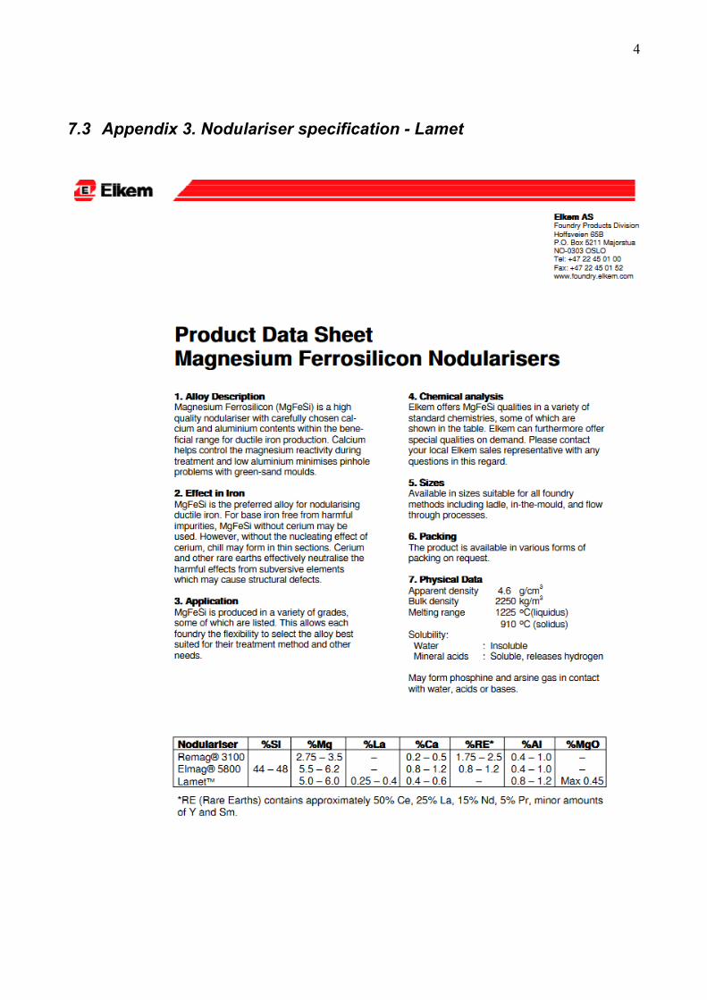
4
7.3 Appendix 3. Nodulariser specification - Lamet
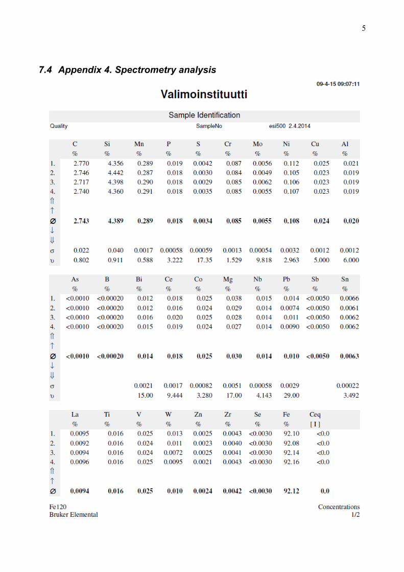
5
7.4 Appendix 4. Spectrometry analysis
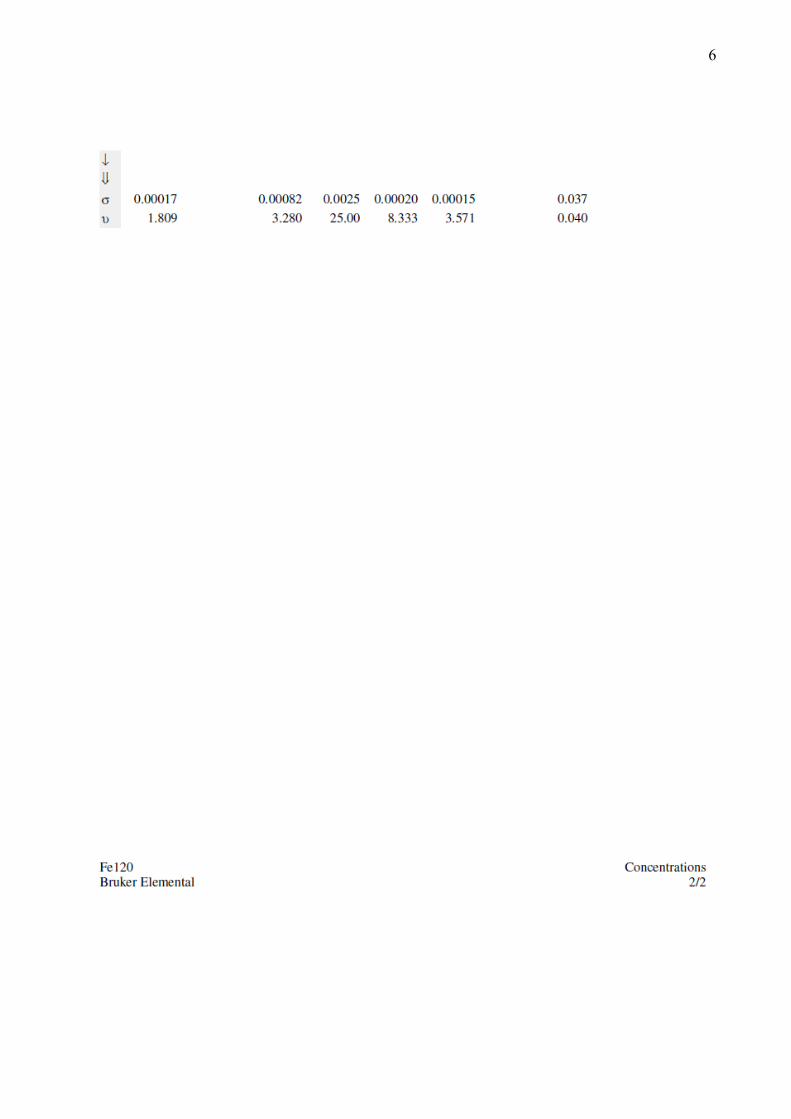
6
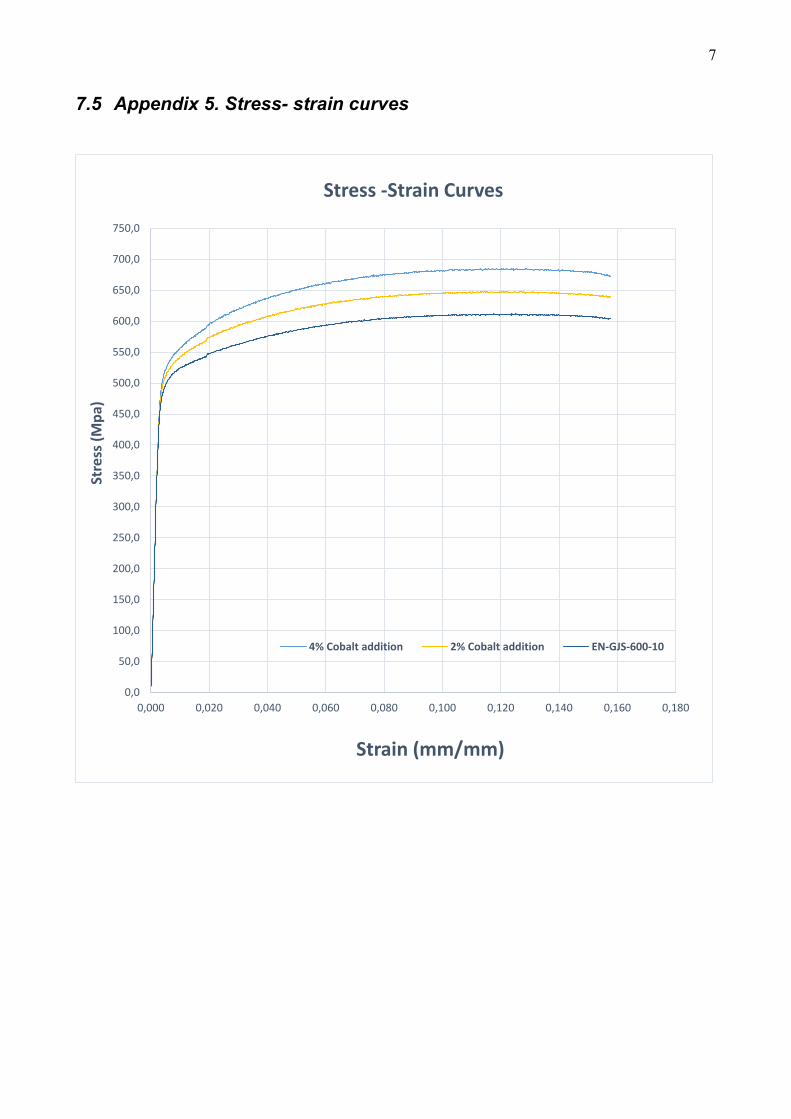
7
7.5 Appendix 5. Stress- strain curves
0,0
50,0
100,0
150,0
200,0
250,0
300,0
350,0
400,0
450,0
500,0
550,0
600,0
650,0
700,0
750,0
0,000 0,020 0,040 0,060 0,080 0,100 0,120 0,140 0,160 0,180
Stre
ss (M
pa)
Strain (mm/mm)
Stress -Strain Curves
4% Cobalt addition 2% Cobalt addition EN-GJS-600-10
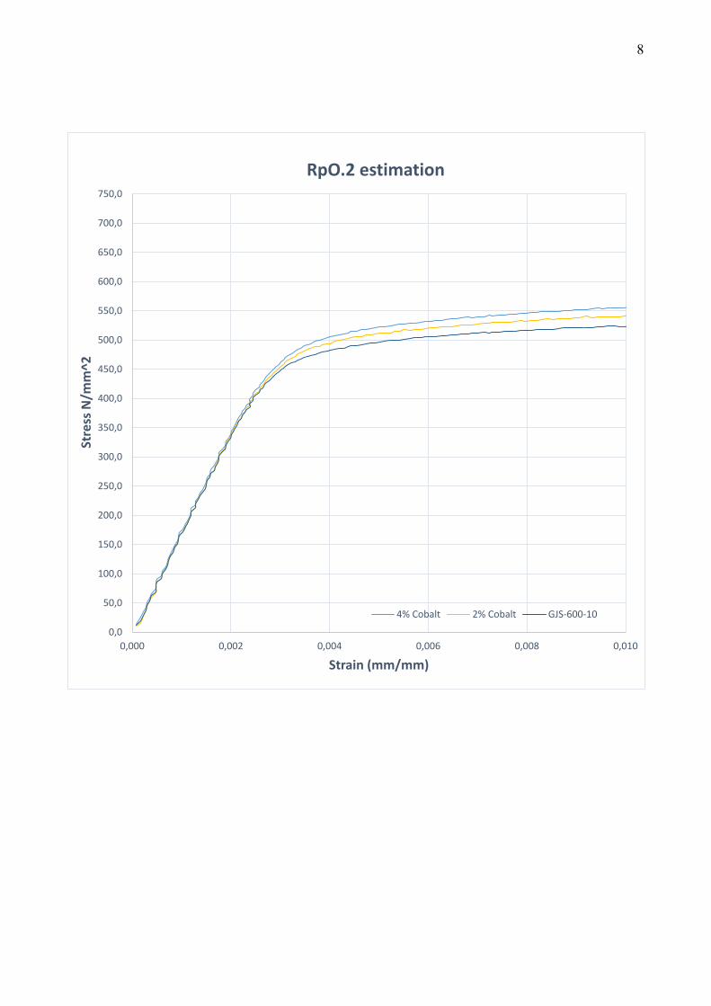
8
0,0
50,0
100,0
150,0
200,0
250,0
300,0
350,0
400,0
450,0
500,0
550,0
600,0
650,0
700,0
750,0
0,000 0,002 0,004 0,006 0,008 0,010
Stre
ss N
/mm
^2
Strain (mm/mm)
RpO.2 estimation
4% Cobalt 2% Cobalt GJS-600-10