high-speed t-38a landing gear extension loads · all strain gages except the one located on the...
TRANSCRIPT

_ ,4//'.7,.;_Y.,_-,_-fzz
3 1176 00162 3884 !
NASA Technical Memorandum 58226 NASA-TM-5822619800016824
High-Speed T-38A Landing Gear
_ Extension Loads
Arthur L. Schmitt
March 1980
National Aeronautics andSpace Administrahon
Lyndon B. Johnson Space CenterHouston. Texas77058
https://ntrs.nasa.gov/search.jsp?R=19800016824 2019-05-10T05:51:18+00:00Z

NASATechnicalMemorandum58226
High-Speed T-38A Landing Gear" Extension Loads
Arthur L.SchmittLyndonB.JohnsonSpaceCenterHouston,Texas
NationalAeronautics andSpace Administration
Scientific and TechnicalInformation Office
1980


CONTENTS
Section Page
SUMMARY ............................. I
INTRODUC TION .......................... I
T-38A LANDING GEAR DESCRIPTION ................. ]
TEST INSTRUMENTATION DESCRIPTION ................ 2
TEST RESULTS .......................... ?
CONCLUDING REMARKS ...................... 4
iii

TABLES
Table Pagc_
I SELECTED FLIGHT DATA FOR T-38 AIRCRAFT WITHOUTSTRUT-DOOR FLAPS .................. 5
II SELECTED FLIGHT DATA FOR T-38 AIRCRAFT WITHSTRUT-DOOR FLAPS ................... 6
FIGURES
F igure Pag_?
1 T-38 main landing gear ................. 7
2 T-38 nose landing gear ................. 8
3 T-38A main landing gear hydraulic schematic ....... 9
4 F-5B strut-door flap mechanism ............. 9
5 T-38A main-actuator pressure history during
gear deployment .................... I0
6 Peak hydraulic pressure during gear deploymentin T-38A with F-5B strut-door mechanism ........ i0
7 Peak hydraulic pressure9 with and without active
strut-door flaps, versus airspeed ........... ii
8 Landing gear deployment envelope for Space Shuttlechase-mission aircraft with strut-door flap actu-
ators. Altitude values are above mean sea level 12
iv
SUMMARY
A series of high-speed landing gear extension flight tests was conducted
at the NASA Lyndon B. Johnson Space Center with a T-38A aircraft. The objec-
tive of the flight tests was to determine the maximum safe airspeed at which
the T-38A landing gear could be extended at high altitude (12 192 meters
. (40 000 feet)), for the purpose of planning Space Shuttle chase missions.
The flight-test results indicate that both altitude and airspeed affect
landing gear extension loads. A safe landing gear extension speed limit atlow altitude will not necessarily be a safe limit at high altitude. Aero-
dynamic forces apparently cause high landing gear extension loads, and flight-test results prove that these forces can be controlled to within acceptable
limits with strut-door flaps.
INTRODUCTION
Flight plans for the first few Space Shuttle missions require a chase
aircraft during the final portions of the return trajectory. The chase air-
craft, a T-38A, will rendezvous with the returning Space Shuttle at I0 668 to12 192 meters (35 000 to 40 000 feet) altitude and follow the Space Shuttle
during its descent while providing assistance to the pilot and photographing
the Space Shuttle return. However, the chase mission poses a technical prob-lem for the T-38A chase aircraft. The landing gear must be extended while
flying very hLgh and very fast to provide the necessary aerodynamic drag to
stay with the Space Shuttle on its steep return glidepath. The maximum land-
ing gear extension speed for a T-38A is normally 123 m/s (240 knots indicated
airspeed (KIAS)), but the chase-aircraft landing gear must be extended at
speeds as great as 144 m/s (280 KIAS corrected for instrument and position
error (KCAS)), and at altitudes as high as 12 192 meters (40 000 feet). To de-" termine the maximum airspeed at which the T-38A landing gear could be extended
for the chase missions, a flight-test program was conducted at the NASA
Lyndon B. Johnson Space Center.
In compliance with the NASA's publication policy, the original units ofmeasure have been converted to the equivalent value in the Systeme Interna-tional d'Unites (SI). As an aid to the reader, the SI units are written
first and the original units are written parenthetically thereafter.
T-38A LANDING GEAR DESCRIPTION
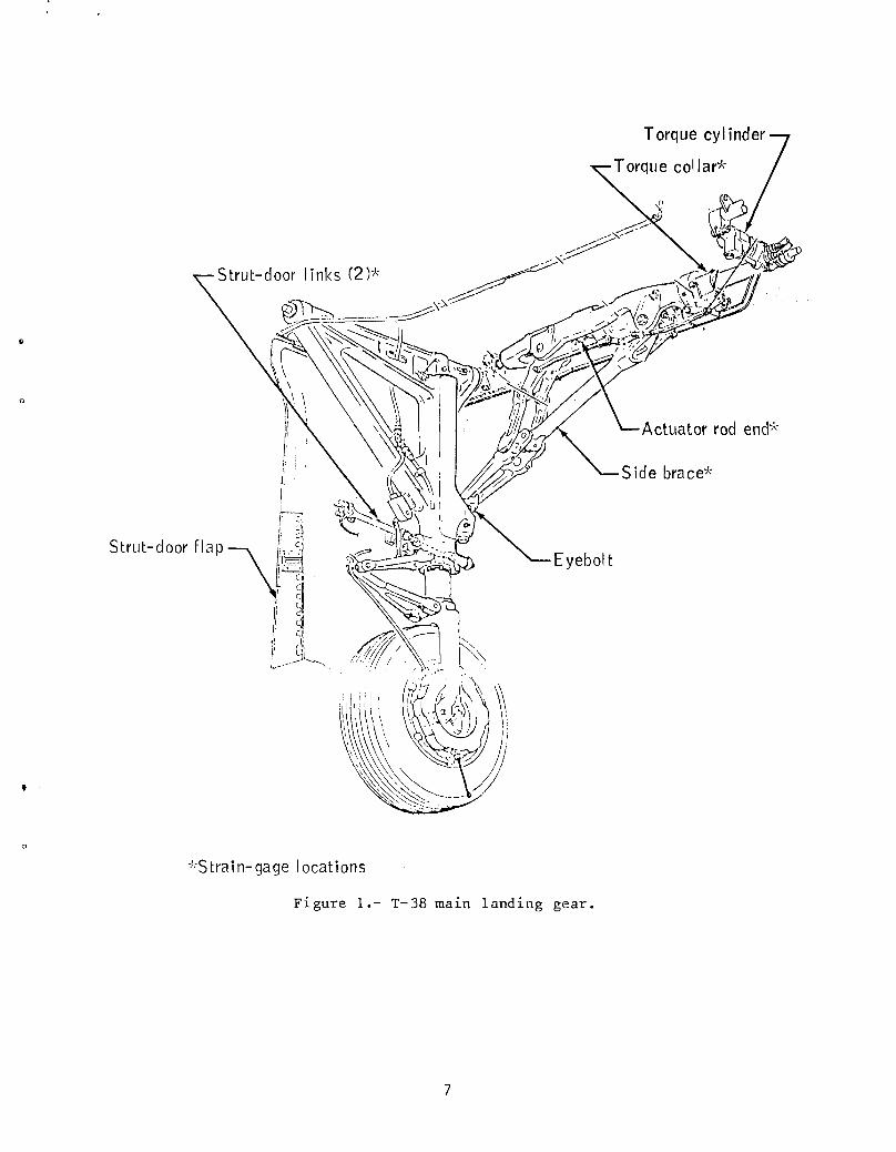
The T-38A landing gear is hydraulically operated and fully retractable
(figs. 1 and 2). The main landing gear retraction mechanism is operated by
two hydraulic cylinders. One cylinder, the main actuator, is located inside
the side-brace assembly, and the other, the torque cylinder, is located be-
side a wing rib. The two cylinders are part of the utility hydraulic system,
which normally operates at a pressure of 20 684 kN/m 2 (3000 Ib/in2). How-ever, all retraction-mechanism components are designed to have a positive
seructural margin of safety I with 24 132 kN/m 2 (3500 ib/in 2) pressure applied
to the hydraulic cylinders at any landing gear position between full up andfull down. The main landing gear hydraulic system includes two flow re-
strictors (fig. 3). These flow restrictors provide hydraulic damping dur-
ing the landing gear extension cycle and control extension and retractionrates. During landing gear extension at high airspeed, gravity and aerody-
namic forces pull the gear down rapidly. A rapid extension is damped by the
flow restrictors, but high hydraulic pressures can exist between the cylin-
ders and the flow restrictors while the sear is in motion. These pressuresmust not exceed 24 132 kN/m 2 (3500 Ib/inZ), the limit pressure for the land-
ing gear system.
All T-38 and F-5 (the fighter version of the T-38) aircraft are equipped
with flaps on the landing gear strut doors. The flaps were designed to aid
in gear retraction, but they also partly overcome the aerodynamic forces that
cause rapid gear extension. All T-38 strut-door flaps were pinned several
years ago because of maintenance problems with the flap mechanisms. However,all F-5 aircraft retain active strut-door flaps. The T-38A aircraft was
tested both with pinned strut-door flaps and with active strut-door flaps;
F-5B parts were used on the test aircraft to activate the flaps (fig. 4).
TEST INSTRUMENTATION DESCRIPTION
The test-aircraft landing gear was instrumented with strain gages
located on the following components.
i. Main-gear side brace
2. Main-actuator rod end
3. Main-gear torque collar
4. Strut-door links
5. Nose-gear drag brace
6. Wheel-door actuator rod
7. Nose-gear-door connector rod
iThe structural margin of safety is the reciprocal of the following ratio:
1.5 times the applied load divided by the ultimate load.

All strain gages except the one located on the main-gear torque collar
were load-calibrated in the laboratory. The torque-collar strain gage was
calibrated on the aircraft so that the gage output could be correlated with
the aircraft torque-cylinder hydraulic pressure. Main-actuator hydraulic
pressure was calculated by dividing the rod-end force by the piston area.
The strain-gage circuits included bridge balancing units and amplifiers.
Gage voltage output was recorded on magnetic tape during flight for subse-quent data reduction° The reduced raw data were in the form of strip charts,which were scaled and read manually. Altitude, airspeed, and other relevant
information were recorded by the T-38A pilot on a tape-recorder voice track.
All major instrumentation components except the strain gages were located i,l
the aft cockpit of the test aircraft°
TEST RESULTSi,
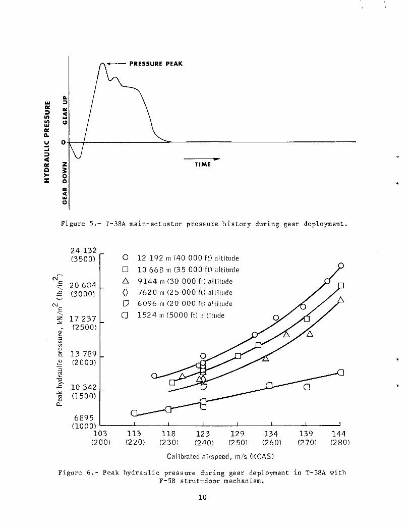
A plot of main-actuator hydraulic pressure versus time during a landing
gear extension is shown in figure 5. The hydraulic cylinders start the gearmechanism in motion, but as soon as the wheels clear the wheel wells, aero-
dynamic and gravitational forces extend the gear rapidly and cause a pres-
sure peak. As the landing gear side brace unfolds, the hydraulic cylinders
gain mechanical advantage, and the gear is slowed by hydraulic damping beforeit reaches the fully extended position. The main-actuator and the torque-
cylinder pressure histories have similar shapes, and the measured peak pres-sures are the same within the accuracy of the instrumentation. The maximum-
pressure peak was used as a criterion for determining safe landing gear
extension speeds for NASA T-38 aircraft that will be used for specialmissions.
The variation in peak hydraulic pressure with respect to airspeed and
altitude is shown in figure 6. At a given calibrated airspeed, the aero-
dynamic forces apparently increase with Mach number as altitude is increased.
The highest Mach number tested was 0.91. Table I includes the airspeed and
altitude information along with other selected flight-test data for the T-38
without strut-door flaps. Table II contains the same information for the
T-38 with strut-door flaps.w
The T-38 and F-5 strut-door flaps have a pronounced effect on landing
gear extension hydraulic-pressure peaks. Activating the strut-door flaps on
. the test T-38A reduced the pressure peaks by almost 30 percent in some cases.
A comparison of the pressure peak data with and without strut-door flaps is
shown in figure 7°
Strain gages on gear components other than those associated with the
hydraulic cylinders indicate the extension loads are low with respect to
landing loads. Thus, these parts have a large positive margin of safety
with respect to high-speed gear extension loads. The landing gear extension
envelope for NASA aircraft flying Space Shuttle chase missions is shown infigure 8.

As a result of these tests, all NASA chase aircraft will undergo special
landing gear component inspections.s
CONCLUDING REMARKS
Both altitude and airspeed affect landing gear extension loads. Landing
gear extensions at high speed and high altitude impose higher than normal ex-
tension loads on the landing gear. These aerodynamic forces on a T-38A can
be controlled to within limits of safety with strut-door flaps. The maximumsafe landing gear extension speed for T-38A aircraft equipped with strut-door
flaps is 144 m/s (280 KCAS) at 12 192 meters (40 000 feet) above mean sea
level and below. Because of the results of the landing gear extension tests,
the strut-door flaps on all T-38A chase aircraft will be activated and spe-
cial landing gear component inspections will be performed.
Lyndon B. Johnson Space Center
National Aeronautics and Space Administration
Houston, Texas, March 28, 1980953-36-00-00-72
4

TABLE I.- SELECTED FLIGHT DATA FOR T-38 AIRCRAFT WITHOUT STRUT-DOOR FLAPS
Airspeed, Mach no. Peak Force_ N (Ib)
m/s (KCAS) hydraulic Side brace Strut-door Strut-door Wheel-door Nosewheel Nosewheel-
pressure, (a) fwd link aft link actuator drag brace door link
kN/m 2 (Ib/in 2) (a) (a)
Altitude, 1524 m (5000 ft)
113 (220) 0.36 11 983 (1738) -20 818 (-4680) -1913 (-430) 445 (100) -578 (-130) 11 121 (2500) 1334 (300)123 (240) .4 14 127 (2049) -24 576 (-5525) -2402 (-540) 801 (180) -1806 (-406) 13 122 (2950) 1468 (330)129 (250) .41 15 410 (2235) -25 533 (-5740) -2882 (-648) 1112 (250) -1201 (-270) 14 412 (3240) 1579 (355)134 (260) .43 16 375 (2375) -26 511 (-5960) -3203 (-720) 1112 (250) -1459 (-328) 15 124 (3400) 1624 (365)
Altitude, 12 192 m (40 000 ft)
123 (240) 0.79 18 726 (2716) -31 227 (-7020) -4804 (-1080) 1281 (288) -2709 (-609) 13 122 (2950) 1397 (314)128 (249) .81 19 691 (2856) -31 227 (-7020) -4448 (-lO00) 1281 (288) -2709 (-609) 14 323 (3220) 1486 (334)130 (253) .83 22 153 (3213) -33 046 (-7429) -5004 (-1125) 1601 (360) -3074 (-691) 14 457 (3250) 1366 (307)L_132 (257) .84 24 469 (3549) -36 311 (-8163) -5507 (-1238) 1601 (360) -3194 (-718) 15 524 (3490) 1379 (310)135 (263) .86 24 683 (3580) -35'857 (-8061) -5872 (-1320) 1770 (398) -3616 (-813) 16 547 (3720) 1455 (327)
aMinus indicates tension.

TABLE ll.- SELECTED FLIGHT DATA FOR T-38 AIRCRAFT WITH STRUT-DOOR FLAPS
Airspeed, Mach no. Peak Force_ N (Ib)m/s (KCAS) hydraulic Side brace Strut-door Strut-door Wheel-door Nosewheel Nosewheel-
pressure, (a) fwd link aft link actuator drag brace door linkkN/m2 (lb/in2) (a) (a)
Altitude, 1524 m (5000 ft)
113 (220) 0.36 8 136 ([180) -14 950 (-3361) -96! (-216) 961 (216) ......123 (240) .4 9 308 (1350) -16 823 (-3/82) -1281 (-288) 1090 (245) ......134 (260) .43 I0 928 (1585) -19 283 (-4335) -1570 (-353) 160[ (360) ......
Altitude) IO 668 m (35 000 ft)
144 280) 0.82 20 960 (3040) -28 887 (-6494) -2722 (-612) 1059 (238) -3256 (-732) 20 208 (4543) 1797 (404)
Altitude, 12 192 m (40 000 ft)
123 (240) 0.79 12 838 (1862) -22 908 (-5150) -2500 (-562) 832 (187) ......131 (255) .84 16 051 (2328) -25 008 (-5622) -3140 (-706) 961 (216) ......
134 (260) .86 17 657 (2561) -27 490 (-6180) -3172 (-713) 992 (223) ......138 (269) .88 18 705 (2713) _-28 193 (-6338) -3114 (-700) 872 (196) -3025 (-680) 16 903 (3800) 1601 (360)142 (276) .90 21 374 (3100) -30 234 (-6797) -3456 (-777) 965 (217) -3|76 (-714) 17 393 (3910) 1601 (360)144 (280) .91 22 946 (3328) -31 004 (-6970) -3203 (-720) 992 (223) -3541 (-796) 19 901 (4474) 1664 (374)
aMinus indicates tension.
Torque cyl inder
orque col lar*
Actuator rod end*
'' Side brace*
*Strai n- gage locations
Figure 1o- T-38 main landing gear.
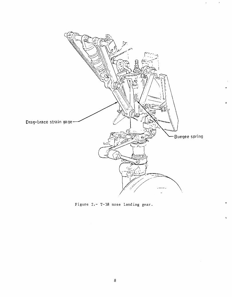
Drag-brace strain gage
Bungee spring
1
Figure 2.- T-38 nose landing gear.
8

GEAR DOWN MAIN ACTUATOR
TORQUE ACTUATOR
-°'-""11ti
S,DE.ACE l U_?_"'__
MECHANISM
- 1AERODYNAMIC FORCEDUE TO SPANWISE FORCE
,ill .cu.oSYSTEM PRESS. 3000 PSI _/
GEAR DoWNFLOW GEAR UP
FLOW
Figure 3.- T-38A main landing gear hydraulic schematic.
t
-......,.. -.... _ -. DOOR
j,
ADJUSTMENIS.,MS ----_
!
¢ /'
O001,'
FLAP g (
?;i /"] STRUT O00R FLAI :)
I ;'. (SHOWN IN CLOSE() STRUT DOOR FLAP /POSITION I T ORSIOI_ BAR
Figure 4.- F-5B strut-door flap mechanism.
9
AK
_u o
o_ TIME
Figure 5.- T-38A main-actuator pressure history during gear deployment.
24 132(3500) O 12 192 m (40 000 ft) altitude
[] I0 668 m (35 000 ft) altitude ,_/
= A 9144 m (30 000 ft) altitude
_ 20684_ i._A" [3(3000) 0 7620 m (25 000 ft) altitude
eJ [T 6096 m (20 000 ft) altitudeE
,.z17 237 _ Q 1524m(5000ft)altittlde__,_/(2500) .'Z
/__ 13 789 _ 0.- (2000)-z
"o
-= I0342 _(1500)
6895(1000) I I I I I I I
103 113 118 123 129 134 139 144(200) (220) (230) (240) (250) (260) (270) (280)
Calibratedairspeed, m/s (KCAS)
Figure 6.- Peak hydraulic pressure during gear deployment in T-38A withF-5B strut-door mechanism.
i0

27 579(4000) 0 Without strut-
door flaps
24 132 [] With active 0 0e4_ (3500) strut-door flaps .
.E
0 °20 684(3000)-
z
-_ 17 237(2500)
__ 13 789"_ (2000)t'-
vt_oa_ 10 342
B
(1500)
6895(I000) I I I I I I I
103 113 118 123 129 134 139 144
(200) (220) (230) (240) (250) (260) (270) (2801
Calibrated airspeed, m/s (KCAS)
Figure 7.- Peak hydraulic pressure, with and without active strut-doorflaps, versus airspeed.
ii

15 240
(50 x 103)
12 192 /(40) //
///////
9144 /(30)--- ¢
-- /
:_ 6096 /-- /D
< (20) ///////////3048 /
(I0) ,//
¢
0 I l I I118 123 129 134 139 144
(230) (2 40) (250) (260) (2 70) (280)
Calibrated airspeed, m/s (KCAS)
Figure 8.- Landing gear deployment envelope for Space Shuttle chase-mission
aircraft with strut-door flap actuators. Altitude values are abovemean sea level.
12

1. Report No. 2. Government AccessionNo. 3. Recipient's Catalog No.
NASA TM-58226
4. Title and Subtitle 5. Report Date
HIGH-SPEED T-38A LANDING GEAR March 1980
EXTENSION LOADS 6. Performing Organization CodeJSC-16497
7. Author(s) 8. Performing Organization Report N,o.
Arthur L. Schmitt
10. Work Unit No,
9. Performing Organization Name and Address 953-36-00-00-72
Lyndon B. Johnson Space Center 11. Contract or Grant No.
Houston, Texas 77058
13. Type of Repor_ and Period Covered
12. Sponsoring Agency Name and Address Technical Memorandum
National Aeronautics and Space Administration
Washington, D.C. 20546 14. Sponsoring Agency Code
15. Supplementary Notes
16. Abstract
Testing of T-38A landing gear extension at high speed and high altitude is described.
The mechanisms are shown together with peak-hydraulic-pressure data during landing
gear deployment with active and inactive strut-door flaps. Results of strain-gagemeasurements of stress on various structural members are included.
17. Key Words(Suggest_ by Author(s)) 18. Distribution Statement
Space Shuttle chase aircraft Flight tests STAR Subject Category: 05
Landing gear Flight safety (Aircraft Design, Testing, and
Landing gear deployment T-38A air- Performance)loads craft
Landing gear design
19. Security Cla_if.(ofthisreport) 20, SecurityClassif.(ofthis _ge) [ 21. No. of Pages I 22. Dice"
Unclassified Unclassified I 17 [ $3.50
*For_lebvtheNationalTechni_llnformatio6 _ice, Springfield,Virginia 22161
.!SC !:orm 1424 (R_ Nuv 75) _ _.S.GOVER_MENTPRINTINGOFFICE 980 - 611-099/]613 NASA---,_

