high-spanning glazing system
TRANSCRIPT
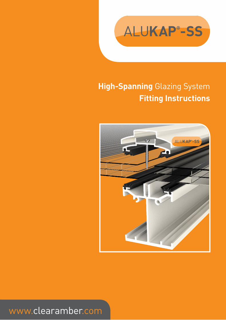
High-Spanning Glazing SystemFitting Instructions
www.clearamber.com

ALUKAP-SS® Low Profile/High Span BarThe ALUKAP®-SS Low Profile glazing bar system offers a spanning range of between three and four meters depending on chosen loading ratings and choice of glazing material.
This High Span Alukap-SS bar outperforms possibly every other bar on the market when it comes to self-supported spanning distances.
ALUKAP-SS® Bar CapThe ALUKAP®-SS Bar Cap provides additional support to the glazing sheets whilst also providing a high standard of finish to the ALUKAP®-SS System.
ALUKAP-SS® Gable BarThe ALUKAP®-SS Gable Bar is the perfect solution for closing off any open ends of a canopy.
ALUKAP-SS® Wall BarThe ALUKAP®-SS Wall Bar provides the required support whilst the top cap sits flush against the wall.
ALUKAP-SS® Wall & Eaves BeamThe ALUKAP®-SS Wall and Eaves Beam provides two systems in one allowing a simple and high quality solution for both aspects of the canopy.
ALUKAP®-SS : Components
www.clearamber.com © Copyright – Clear Amber Group Ltd – March 2019

1. Cut the ALUKAP®-SS Wall Plate to the overall external width of your roof structure. Drill holes through the back of the ALUKAP®-SS Wall Plate and screw/bolt securely with suitable stainless steel fixings suited to the wall. Fit ALUKAP® bar gasket on to the base rail and upright rail.
2. Cut the ALUKAP®-SS Eaves Beam to the overall external width of your roof structure. Screw/bolt securely to the top of your window frame or post bracket with suitable stainless steel fixings. Fit ALUKAP® bar gasket on to the base rail and upright rail.
3. Now cut the ALUKAP®-SS Bar Cap lengths to the same width as the ALUKAP®-SS Eaves Beam and Wall Plate. Offer up the top and bottom ALUKAP®-SS Bar Cap on to the ALUKAP®-SS Eaves Beam and Wall Plate respectively.
ALUKAP®-SS Glazing DeductionsGlazing deduction guidelines are shown below for the Alukap-SS bar system for ALUKAP®-SS wall bars, ALUKAP®-SS standard/centre bars and ALUKAP®-SS gable bars. However these may need to amended depending on chosen glazing materials and glazing centres.
Samples are readily available to users to test and verify the exact sizes according to their site requirements.
Deduct 38mm Deduct 15mm Deduct 45mm
www.clearamber.com© Copyright – Clear Amber Group Ltd – March 2019
NOTE: FOR HEAVY LOADS OR LONG SPANS
For longer spans and / or heavier loading we recommend posts for additional support below the wall plate also.
Inasmuch as Clear Amber have no control over the circumstances in which our material may be used, or site specific parameters, we cannot guarantee that any particular results will be achieved. Users should carry out their own tests to determine the suitability of the material for their application. Installers should satisfy themselves that published permissible loadings and bar spacings for ALUKAP®-SS structures, together with any supporting posts, frames, or walls and fixings, are sufficient to provide adequate strength for the intended use and to meet regional loading requirements. Installers should also obtain their own job-specific structural engineer’s report for their individual site. Samples are readily available to users to test and verify the exact sizes according to their site requirements.

4. Cut the first ALUKAP®-SS High Span/Low Profile base bar to the correct length to allow it to rest between the top and bottom ALUKAP®-SS Bar Caps. Measure the bolt fixing position from the end of the ALUKAP®-SS base bar for drilling a hole through the ALUKAP®-SS Span base bar and down through the bold flange on the ALUKAP®-SS Eaves Beam and Wall Plate. This will vary between 40mm and 70mm depending on the pitch).
5. Measure out the positions of the ALUKAP®-SS High Span/Low Profile bars for the rest of the roof and mark them on the ALUKAP®-SS Bar Cap, allowing for a minimum of 2mm either side of the glazing for thermal expansion appropriate to the chosen glazing material.
6. Cut the rest of the ALUKAP®-SS Span Base Bars to exact length
www.clearamber.com © Copyright – Clear Amber Group Ltd – March 2019
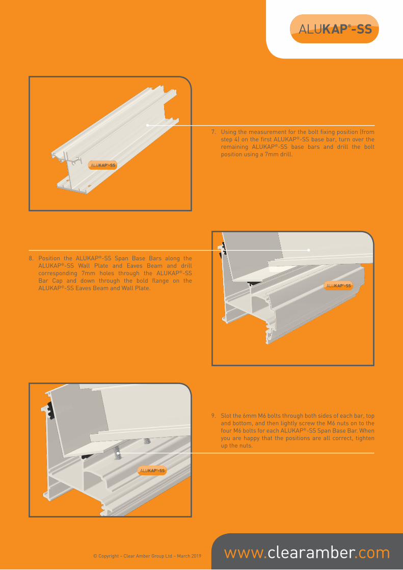
7. Using the measurement for the bolt fixing position (from step 4) on the first ALUKAP®-SS base bar, turn over the remaining ALUKAP®-SS base bars and drill the bolt position using a 7mm drill.
8. Position the ALUKAP®-SS Span Base Bars along the ALUKAP®-SS Wall Plate and Eaves Beam and drill corresponding 7mm holes through the ALUKAP®-SS Bar Cap and down through the bold flange on the ALUKAP®-SS Eaves Beam and Wall Plate.
9. Slot the 6mm M6 bolts through both sides of each bar, top and bottom, and then lightly screw the M6 nuts on to the four M6 bolts for each ALUKAP®-SS Span Base Bar. When you are happy that the positions are all correct, tighten up the nuts.
www.clearamber.com© Copyright – Clear Amber Group Ltd – March 2019

10. Now fit ALUKAP®-SS bar gasket on to both sides of each ALUKAP®-SS Span Base Bar and also on to the ALUKAP®-SS Bar Cap along the direction of the Eaves Beam and Wall Plate.
11. Next, offer up the first glazing panel. On the upper outside edge of the end ALUKAP®-SS Base Bar add a packer the same thickness as the glazing material.
12. Ensure that ALUKAP®-XR Endstop Bar is fitted to the lower ends of the glazing material.
www.clearamber.com © Copyright – Clear Amber Group Ltd – March 2019

13. Measure the required length for the ALUKAP®-SS Top Bar Base Cap allowing for the overhang in to the gutter and the continuation at the wall plate end up to the wall abutment. Secure the ALUKAP®-SS Top Bar Base Cap to the first ALUKAP®-SS Base Bar using suitable stainless steel screws, taking care not to over-tighten the screws, but making sure that the gasket are creating a uniform seal with the glazing material. The fixing torque for standard screws in the ALUKAP®-XR bars that we recommend in most conditions is 6-7.
14. Drill a 2.5mm hole in the ALUKAP®-SS Top Bar Base Cap for the ALUKAP®-XR endcap screw. Secure the ALUKAP® End Cap on to the ALUKAP®-SS Top Bar Base Cap. It is normally recommended that this covers the ALUKAP®-XR Endstop Bar, which will be fitted to the glazing material.
15. Then offer up the next glazing panel and repeat the procedure above to fix the next intermediate ALUKAP®-SS Top Bar Base Cap between the first and second glazing panel. Then continue along the rest of the roof until all glazing panels are secured.
www.clearamber.com© Copyright – Clear Amber Group Ltd – March 2019

www.clearamber.com
16. Now carefully cut the ALUKAP®-SS Top Bar Top Cap to the accurate length required for a perfect aesthetically pleasing finish. For gable end or wall abutments use the ALUKAP®-SS Gable Bar or Wall Bar Top Cap. Snap the ALUKAP®-SS Top Bar Top Caps on to the ALUKAP®-SS Top Bar Base Caps along the whole length of the bar. Use a suitable rubber / plastic headed hammer for this action and avoid heavy impact, to avoid damage to the ALUKAP®-SS bar and the glazing materials.
17. Fix QUADRAFLO gutter brackets to the front face of the ALUKAP®-SS Eaves Beam, and then fit the remaining desired Quadraflo gutter and downpipe as required. QUADRAFLO Deep Style gutter brackets are designed to snap fix in to the front of the ALUKAP®-SS Eaves Beam, and only then require location fixings as desired, saving time on site.
18. Fit a flashing tape or lead to the back wall and any adjacent wall as required
ALUKAP®-SS | FI | V3.05 | 03-19
Inasmuch as Clear Amber have no control over the circumstances in which our material may be used, or site specific parameters, we cannot guarantee that any particular results will be achieved. Users should carry out their own tests to determine the suitability of the material for their application. Installers should satisfy themselves that published permissible loadings and bar spacings for ALUKAP®-SS structures, together with any supporting posts, frames, or walls and fixings, are sufficient to provide adequate strength for the intended use and to meet regional loading requirements. Installers should also obtain their own job-specific structural engineer’s report for their individual site. Samples are readily available to users to test and verify the exact sizes according to their site requirements.
© Copyright – Clear Amber Group Ltd – March 2019. No part of this publication may be copied, reproduced, scanned, or stored in any electronic database, whether in whole or in part, in any form or by any means, without permission in writing from Clear Amber. Clear Amber will not hesitate to take appropriate legal action if its rights in this respect are infringed.
WARNING : REGISTERED DESIGNS & PATENTSThe IP of the designs in this brochure are protected by internationally registered design rights. Many products are also protected with active or pending Patents. Clear Amber will not hesitate to take appropriate legal action if its rights in this respect are infringed.