high resolution industrial ct systems: advances and ... 2014 1 high resolution industrial ct...
TRANSCRIPT

NDE 2014
1
High resolution industrial CT systems:
Advances and comparison with synchrotron-based CT
Oliver BRUNKE*, Eberhard NEUSER
*, Alexander SUPPES
*, Samaresh CHANGDAR
+
*GE Sensing & Inspection Technologies GmbH,
Niels-Bohr-Str. 7, 31515 Wunstorf, Germany + GE India Industrials PVt Ltd, 401, Delphi C Wing
Hiranandini Business Park, Powai, Mumbai, India
E-mail: [email protected]
Abstract. Nowadays, X-ray tube-based high-resolution CT systems are widely used in scientific research
and industrial applications. Compact XCT systems are available that can reach resolutions down to 1 µm
and below. But the potential, convenience and economy of these lab systems is often underestimated. The present paper shows the comparison of sophisticated conventional µCT with synchrotron radiation-
based µCT (SRµCT). The different aspects and characteristics of both approaches like spatial and density
resolution, penetration depth, scanning time or sample size is described in detail. Beside this, the
advances in technology of industrial high resolution CT systems are shown.
The paper also presents recent advances in the area of industrial high resolution CT systems from phoenix product line of General Electric. All major parts are designed to make the system extremely
stable during the data acquisition process. So, the system is equipped with granite base and very precise
rotation unit. The unique nanofocus tube technology with build-in cooling system stabilizes the tube and
at the same time the diamond based target allows high photon flux at very small focal spot sizes. The
unique detector with excellent contrast resolution and SNR is also thermally stabilized. Also, the user friendliness is increased through the fully automated process chain starting with detector calibration and
going through acquisition and data reconstruction process with automated volume data evaluation
The application results of this new technology show its high potentials for usage of the state of the art
laboratory systems in the industrial and scientific application fields of material research, metrology,
petro-industry, etc. To compare the potentials of laboratory based CT with synchrotron based CT, different samples were used: e.g. a low-carbon steel sample, and an aluminium multi-phase sample
(AlMg5Si7) and some other. Concerning measurement costs, scanning volume, accessibility and user-
friendliness sub-µXCT has significant advantages in comparison to synchrotron-XCT.
1. Introduction
High resolution CT nowadays is a well established method for numerous industrial
applications [1][2][3] as well as wide range of research areas [4][5]. For both fields the choice of the optimal method is strongly driven by many different factors like sample size
and composition, required spatial and contrast resolution or scanning volume and time, etc.
For example in today’s quality market, achieving the smallest feature recognition possible
in the inspection process has become a higher priority than ever before. Due to complex
geometries and miniaturization of many high reliability components in the automotive, electronics and aerospace industries, achieving this level of feature recognition has also
become increasingly difficult. CT techniques are used to measure internal distances or the
internal wall thickness of complex castings and areas which are often inaccessible for
National Seminar & Exhibition on Non-Destructive Evaluation, NDE 2014, Pune, December 4-6, 2014 (NDE-India 2014)
Vol.20 No.6 (June 2015) - The e-Journal of Nondestructive Testing - ISSN 1435-4934www.ndt.net/?id=17873

NDE 2014
2
optical scanners or conventional tactile coordinate measurement machines. The CT volume
data provides information for reverse engineering or first article inspection of the entire part by merging it with the CAD model to generate a variance map of both data sets [6][7][8].
Combined, these capabilities contribute to early detection of process and product
weaknesses therefore increasing yield and productivity.
Regarding high resolution computed tomography with voxel sizes of a few microns or even
in the submicron range the state of the art benchmark is defined by CT setups which use synchrotron radiation for the X-ray source. Synchrotron radiation based CT was introduced
in the 1980s by Bonse et al [9]. Nowadays it is a standard experiment for users from
scientific research as well as industry at numerous Synchrotron laboratories worldwide. The
main advantages of these setups are the highly collimated and almost parallel beam and the
photon flux which is several orders of magnitude higher than for conventional X-ray sources. Due to this high flux monochromators can be effectively used to perform CT scans
with monochromatic radiation at the desired energy level.
However, in recent years major steps in important hardware components like open
microfocus or even nanofocus X-ray tube technology (the later was commercially
introduced the first time by phoenix|x-ray in 2001) on the one side and the development of highly efficient and large flat panel detectors (by e.g. GE, Perkin-Elmer, Varian or
Hamamatsu) using CCD or CMOS technology on the other, allowed the development of
very versatile and high resolution laboratory CT systems like the nanotom m (see next
section) which are commercially available. Electromagnetic focusing of the electron beam
allows generating X-ray beams with an emission spot diameter down to well below one µm which is essential for CT examination with voxels in the sub-micron range. These
characteristics principally allow CT measurements which, with respect to spatial resolution,
can compete with many absorption contrast setups at synchrotron radiation facilities [10].
The advantages of laboratory X-ray tube based setups like e.g. its accessibility, user-
friendliness, high cost effectiveness, large scanning area and thus comparably high scanning speed (especially for cone beam based systems like the nanotom) are
unfortunately still quite often not known or neglected.
The purpose of this work is to show the potential of high resolution laboratory CT scanners
as a powerful complementary approach, to support the costly, time consuming and complex
examination at synchrotron facilities. In the following the comparison of datasets obtained with both, an absorption contrast SRµCT setup and a recently developed high resolution
cone beam laboratory scanner will show the unique properties of both approaches. The
advantages (and limitations) of both methods are shown at several example specimen with
high and low absorption characteristics. These cover the materials science sector as well as
the biomedical world. Also, a comparison with an older state of the art sub-µCt system is made.
2. The CT systems
2.1 The phoenix nanotom m laboratory CT system
The first nanotom CT system for sub-micron scans was introduced in 2006 by phoenix|x-ray in order to cover the growing demands for a compact laboratory CT system for spatial
resolutions which could be reached only by synchrotron radiation based setups on the one
hand. On the other it should give the user extreme high flexibility for applications in fields
such as materials science, micro mechanics, electronics, geology, and biology to name a
few. Therefore, it is particularly suitable for examination of sensors, complex mechatronic

NDE 2014
3
samples, microelectronic components as well as for material samples such as synthetic
materials, ceramics, sintered alloys, composite materials, mineral and organic samples. The nanotom system was used for several years as the state of the art tomography system for
material science labs, and also in this paper it will be referred as a state of the art sub-µCT
device.
To further increase the application range, the successor system nanotom m was
introduced 2010 by GE Sensing and Inspection Technologies within its phonix|x-ray product line. This system incorporates most recent developments of major components of
that belong to a CT system like x-ray tube, x-ray detector and very user friendly software
package. Also, the overall system design (granite based manipulator, an air-conditioned
cabinet, a high accuracy direct measuring system, a very precise air bearing rotating unit as
well as vibration insulation of the manipulator) significantly contributes to the to excellent overall image quality.
2.1.1 Components of the nanotom m
In order to cover the widest possible range of samples, the system is equipped with
the first commercially available 180kV high power nanofocus (HPNF) tube. This tube was
further optimized regarding the long term stability specially for the nanotom m system. The
internal cooling of tube reduces effectively thermal drifts and therefore allows even sharper
imaging also when running very long scanning times. Optionally, a diamond target is available for extremely high focal spot stability and up to 2 times faster data acquisition at
the same high image quality level.
This source can be operated in four different modes. On the one hand, in the so
called nanofocus mode it provides an X-ray spot size of down to approximately < 0.9 µm
which allows excellent detail detectability and can be used for highest resolution CT scans with sub-micrometer voxel size. Due to the penumbra effect, the spot size predominates the
images sharpness for extreme magnifications (for details see e.g. [11]). In Fig. 1 the
resolution capability of the high power nanofocus source is demonstrated. It shows that the
0.6 µm structure (line width) of the JIMA test pattern (designed by the Japan Inspection
Instruments Manufacturers' Association for testing high resolution X-ray equipment [12]) can clearly be resolved with more than approximately 20% of the CTF, showing the X-ray
source size can be as small as below 0.9 µm.
Fig. 1: X-ray images of test patterns showing the capabilities of resolution and detail detectability of
phoenix|x-ray’s high power nanofocus tube. On the left side, the 0.6 µm line pair structure of the JIMA test pattern is clearly resolved
0.0 0.5 1.0 1.5 2.0 2.5 3.0 3.5 4.0 4.5 5.0 5.5 6.0
0.0
0.2
0.4
0.6
0.8
1.0
Re
l. In
t.
Dist [µm]
Line profile

NDE 2014
4
In the high power mode (up to 15 Watts at the target) on the other hand, the tube has
enough penetration power to examine high-absorption samples like copper, steel or tin alloys and thus allowing e.g. the analysis of new connection systems for electronic devices
or high absorbing geological samples, etc. The tube is equipped with a transmission type
target. This means the target is a thin layer (a few microns) of W or Mo which has been
sputtered on the beryllium or chemical vapor deposited (CVD) diamond exit window which
is hit by the focused electron beam. For the transmission geometry, the X-rays are emitted in the same direction as the incoming electron beam.
On the detection side, a unique GE flat panel detector is firstly used in an industrial
CT device. This detector is temperature stabilized and is based on amorphous silicon (a-Si)
panel with CsI scintillator deposited as needle structure. It offers 3,072 x 2,400 pixels with
100mm pixelsize and excellent dynamic range of up to 10,000 : 1, which is up to ~10x higher compared to the detector in the older nanotom systems. The high dynamic range and
signal-to-noise ratio (SNR) allows up to 4 time faster CT acquisition at the same signal-to-
noise ratio. To further increase the field of view, the 1.5-fold virtual detector possibility can
be used.
For reconstruction of the volume data GE Sensing & Inspection Technologies uses a proprietary implementation based on Feldkamps cone beam reconstruction algorithm
[13]. The reconstruction software contains several modules for artefact reduction (e.g. beam
hardening, ring artefacts, drift compensation) to optimize the results. In Fig. 2, the effect of
the ring artefact suppression method is shown. Here, two identical cross sections of a
cortical bone sample (human bone) scanned with the nanotom at 90 kV and 150 µA and 1.8 µm voxel size are shown. The original study was performed by M. Dalstra et al using the
SRµCT setups at HASYLAB/DESY to quantitatively evaluate the remodelling process in
osteoporotic cortical bone [14]. For quantitative analysis of the datasets it was essential to
minimize the artefacts in the reconstructed volume. As it can bee seen in Fig. 2, the
approach implemented by phoenix|x-ray effectively eliminates the ring artefacts and therefore a further quantitative analysis could also be performed on the nanotom CT
datasets as it was done with the results of the SRµCT scans. One remarkable result of the
shown nanotom data is the high contrast resolution which even allows a separation of the
different density phases in the bone [14].
Fig. 2: Cross section of cortical bone sample scanned with the nanotom. Due to an effective ring artifacts suppression a segmentation of the different phases in the bone structure becomes possible.
1 mm
(a) (b)

NDE 2014
5
With datos|x 2 CT software, the entire CT process chain can be fully automated,
significantly reducing operator time: Once the appropriate setup is programmed, the whole scanning and reconstruction process including volume optimization features or surface
extraction runs without any operator interaction. Furthermore, 3D metrology or failure
analysis tasks performed with third party programs can also be executed automatically.
Once programmed, automatic creation of a first article inspection report even with complex
internal geometries can be provided within an hour.
2.1.2 Performance comparison with state of the art sub-micron CT
To compare the performance of the new nanotom m CT device, a typical sample from the material science application range was chosen: a metallic foam from an material
development and characterization lab in automotive industry, sample size ca. 2x2x3 cm,
fig. 3. The results made with nanotom m show a clear improvement comparing with a state
of the art sub-micron CT system: the signal-to-noise ration is improved by 100% and thus,
finer details can be distinguished in the volume data. This benefit can be achieved due to diamond window of the x-ray tube on the one hand and low noise high contrast GE x-ray
detector on the other hand.
Fig. 3. Comparison of scans of a metallic foam on the state of the art sub-micron CT system (older nanotom)
(left) and on the new phoenix|x-ray nanotom m CT system (right). In both cases, the voxel size of 15µm, the tube settings and scanning time of 1 hour were identical
2.2 The synchrotron CT setup
Synchrotron radiation based micro-CT systems (SRµCT) offer significant advantages by their adjustability, partial coherence and nearly parallel beam of high brilliance [18]. These
advantages cause fewer artifacts, improved contrast and resolution, as well as faster
recording for synchrotron tomography. In [16], a comparison between synchrotron based
and laboratory CT system is shown. There, a synchrotron based µCT setup at
HASYLAB/DESY in Hamburg/Germany was used to investigate some higher absorbing materials and to compare the results with the state of the art sub-µCT.
The ID19 beamline of ESRF—European Synchrotron Radiation Facility in
Grenoble [17, 18] provided monochromatic X-rays with beam energy of 29 kV in parallel
beam geometry. The SRµCT projections were recorded by a 2D-CCD camera with
2048x2048 pixels and an effective pixel size of 0.3 mm. For reconstruction 1500
1 mm

NDE 2014
6
projections were acquired. The samples were measured in phase contrast mode using a
distance sample-to-detector of 39 mm. The recordings took about 15 min.
3. Comparison
Two different sample types have been chosen to be studied by SRµCT as well as with high resolution industrial laboratory sub-micron CT system. Identical regions of the specimen
described in the following have been scanned by both systems. In order to allow a
quantitative comparison, the resulting volume data had to be registered to each other using
either a software described in [15] or manually using e.g. VGStudio MAX by Volume
Graphics, Heidelberg/Germany. In the material science several typical tasks can be solved using CT technology. One
common task is to quantitatively and qualitatively investigate inhomogeneities like pores,
cracks, inclusions of higher and lower density, … . Classically used standard methods are
mechanical slicing together with subsequent evaluation using either optical microscopy or
even scanning electron microscopy (SEM). In the last years, x-ray CT becomes more and more popular due to its capability for volumetric and non-destructive evaluation of the
materials.
3.1. Low-carbon steel sample
The low-carbon steel investigated in this paper was produced using continuously cast
condition and has max. diameter of ca. 0.5 mm. Inhomogeneities that are of special interest
for this kind of samples are pores and different phases like CaAl-, MgO-, CaS-, NiC-
phases. The table 1 shows the CT settings that were used to achieve the results. The results are comparatively shown in the fig. 4.
Table 1. CT settings for low-carbon steel sample
CT Parameter State of the art
sub-µCT
New nanotom m SRµCT,
ID19 beamline, ESRF Grenoble
Voltage (kV)/ beam
energy
50, W Target 50, W Target 30
Current (µA) 480 480 -
Tube Mode 3 3 -
Voxel size (µm) 0,5 0,5 0,3
Scanning time (min) 180 180 15
Fig. 4. Comparison of CT results for low carbon steel sample between state of the art sub-µCT (left), sub-
µCT with new nanotom m (middle) and SRµCT (right)
SRµCT at ID19 beamline/
ESRF Grenoble [17] sub-µCT with new nanotom m State of the art sub-µCT
NDE 2014
7
As it was already reported in [17], the ring artefacts are most pronounced for the
SRµCT-data, whereas both laboratory devices show almost no ring artefacts due to special settings in the hard- and software on the one hand and also due to unique temperature
stabilized detector in the nanotom m device. Ring artefacts are well known and are caused
by non-stabilities or faults of the detector pixels. In [17], it was also reported that both, state
of the art sub-µCT as well as SRµCT, shows very comparable contrast and spatial
resolution. But also some drawbacks of the laboratory system were shown: this is the signal-to-noise ratio and the edge sharpness in the volume data.
With the new nanotom m, the sharpness could be increased by 40% comparing to
the older state of the art sub-µCT. This fact can also be clearly seen in the fig. 4. Also, the
SNR is increased by ca. 100%, compare also with fig. 3. These both positive advances are
not only due to new GE detector technology, that is firstly available within the new nanotom m system for industrial applications, but also due to increased thermal stability for
the whole system (compare section 2.1).
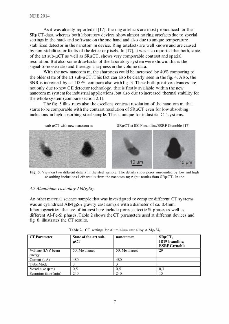
The fig. 5 illustrates also the excellent contrast resolution of the nanotom m, that
starts to be comparable with the contrast resolution of SRµCT even for low absorbing
inclusions in high absorbing steel sample. This is unique for industrial CT systems.
Fig. 5. View on two different details in the steel sample. The details show pores surrounded by low and high
absorbing inclusions Left: results from the nanotom m; right: results from SRµCT. In the
3.2 Aluminium cast alloy AlMg5Si7
An other material science sample that was investigated to compare different CT systems
was an cylindrical AlMg5Si7 gravity cast sample with a diameter of ca. 0.4mm.
Inhomogeneities that are of interest here include pores, eutectic Si phases as well as
different Al-Fe-Si phases. Table 2 shows the CT parameters used at different devices and fig. 6. illustrates the CT results.
Table 2. CT settings for Aluminium cast alloy AlMg5Si7
CT Parameter State of the art sub-
µCT
nanotom m SRµCT,
ID19 beamline, ESRF Grenoble
Voltage (kV)/ beam
energy
50, Mo Target 50, Mo Target 29
Current (µA) 480 480
Tube Mode 3 3
Voxel size (µm) 0,5 0,5 0,3
Scanning time (min) 240 240 15
sub-µCT with new nanotom m SRµCT at ID19 beamline/ESRF Grenoble [17]

NDE 2014
8
Fig. 6. Comparison of CT results for AlMg5Si7: state of the art sub-µCT (left), sub-µCT with new nanotom m
(middle) and SRµCT (right)
Pores and ferroaluminides are clearly visible in all three results, as well as Mg2Si
phases. But again, the nanotom m results shows better SNR and contrast resolution
comparing with the state of the art sub-µCT. In the STµCT results, also the phase contrast
effects are clearly observable. This is due to very monochromatic x-ray spectrum, that is typical for synchrotron radiation sources. The phase contrast leads to a kind of “ringing”
resp. edge amplification and can be advantageous for visual inspection as well as a
drawback for automated inspection that often requires some volume segmentation.
4. Summary and outlook
The present study aimed to show on the one hand new advances in laboratory sub-µCT
systems and on the other hand a comprehensive comparison of performance between commercial high end CT scanner with a nanofocus x-ray tube and a absorption synchrotron
radiation based CT setup. Two samples with different absorption characteristics (a steel and
an aluminum sample) have been scanned in a sub-micron voxel size. The chosen specimens
are good examples for typical application from the material science.
The analysis of the scans reveals that the new phoenix|x-ray nanotom m has clear advantages comparing to the older state of the art laboratory sub-µCT systems due to
significant improvements in overall system design, new temperature stabilized detector
with better contrast resolution and high performance cooled nanofocus x-ray tube with
much better flux at the same focal spot sizes due to diamond window. This system gives
excellent data quality which in many cases can even compete with SRµCT data. In [16] was reported that especially in some cases where higher voltages are required to penetrate
bigger samples, the state of the art sub-µCT systems can even outperform the SRµCT
systems with respect to spatial resolution. In other cases, the SNR and the resolution was
very comparable. Also, the bigger scanning volume of a cone beam system like nanotom m
is an advantage and can lead to even lower scanning times for bigger samples. With the new nanotom m system even better results can be expected for larger samples with higher
absorption materials, what will be put under examination within next research steps.
The synchrotron radiation CT on the other hand provides an excellent contrast
resolution, precisely adjustable monochromatic radiation and therefore no beam hardening
artefacts. So, for situations in which optimal contrast resolution or artefact free data is needed, the synchrotron radiation based CT would be the system of choice.
In total, the major pros of the laboratory scanner are its large field of view, large
scanning volume, high penetration power due to the 180kV tube, scanning speed (scanned
volume per time), ease of use and overall cost effectiveness. Also, the recently developed
high performance industrial sub-µCT scanners like nanotom m by phoenix x-ray can
State of the art sub-µCT sub-µCT with new nanotom m SRµCT at ID19 beamline/ ESRF Grenoble [17]

NDE 2014
9
adequately support and complement research projects where high quality CT data is
required. Due to its flexibility, the nanotom can be used for both, extreme high resolution scans with sub-µm voxel size of small samples on the one hand or also fast scans of high
absorbing (or larger) specimen using the high power mode on the other.
References
[1] Roth, H. Mazuik B., “ What you can’t see can hurt you”, Quality Test and Inspection, 5, (2003)
[2] Moller – Gunderson, D., “ When 2D X-ray isn’t enough” SMT , 8, (2007). [3] Nier, E., Roth, H., “ Analysis of Crimp Interconnections by Microfocus Computed Tomography” XXX,
2004. [4] Bonse, U., (Editor.), “ Developments in X-Ray Tomography IV” SPIE, Wellingham WA, (2004).
[5] Bonse U., (Editor.), “ Developments in X-Ray Tomography V”, SPIE, Wellingham WA, (2006). [6] Obrist, A. et al., “ First Article Inspection Based on Industrial X-ray Computed Tomography”, Materials
Testing and Research, International Conference, Nuremburg, 177-180 (2001). [7] Brunke O., “ Dimensionelles Messen mit hochauflösender 3D-CT“ , QZ, 62-64 (2008).
[8] Suppes, A., Neuser, K., „Metrology with µCT: precision challenge” in Developments in X-ray Tomography VI, edited by Stuart Stock, Proceedings of SPIE Vol. 7078, (2008)
[9] Bonse U., Busch F., „X-ray computed microtomography (µCT) using synchrotron radiation (SR)., Prog. Biophys. Mol. Biol., 65(1-2), 133-169 (1996)
[10] Withers, P., “ X-ray nanotomography”, Materials Today, 10(12), 26-34 (2007) [11] Brockdorf, K. et al., “ Sub-micron CT: visualization of internal structures” in Developments in X-ray
Tomography VI, edited by Stuart Stock, Proceedings of SPIE Vol. 7078, (2008). [12] Japan Inspection Instruments Manufacturers' Association, http://www.jima.jp
[13] Feldkamp, L.A., Davis, L.C., Kress, J.W. “ Practical cone-beam algorithm”, Journal of the Optical Society of America A, 1(6), 612-619 (1984)
[14] Dalstra, M. et al., “ Osteonal mineralization patterns in cortical bones studied by synchrotron radiation-based computed microtomography and scanning acoustic microscopy”, in Developments in X-ray
Tomography IV, edited by U. Bonse, SPIE Vol. 5535, 143-151 (2004) [15] Drews S, et al, “ Three dimensional characterization of the bone-cartilage interface using micro
computed tomography” in Developments in X-ray Tomography VI, edited by Stuart Stock, Proceedings of SPIE Vol. 7078, (2008).
[16] Brunke, O, “ Comparison between x-ray tube based and synchrotron based µCT”, 10th European Conference on NDT, Moscow, June 7-11, Spektr, (2010)
[17] J. Kastner, B. Harrer, G. Requena, O. Brunke, “ A comparative study of high resolution cone beam X-ray tomography and synchrotron tomography applied to Fe- and Al-alloys”, in NDT&E Int. vol. 43, pages
599-605, (2010) [18] http://www.esrf.eu/