high rate behavior and discharge limits in micro-pattern
TRANSCRIPT

Nuclear Instruments and Methods in Physics Research A 424 (1999) 321—342
High rate behavior and discharge limits in micro-pattern detectors
A. Bressan!, M. Hoch!, P. Pagano!, L. Ropelewski!, F. Sauli!,*, S. Biagi", A. Buzulutskov#,M. Gruwe$, G. De Lentdecker%, D. Moermann&, A. Sharma'
! CERN, PPE Division, CH-1211, Geneva 23, Switzerland" University of Liverpool, Liverpool, UK
# Budker Institute for Nuclear Physics, Novosibirsk, Russia$ DESY-University, Hamburg, Germany
% ULB-VUB, Bruxelles, Belgium& University of Karlsruhe, Karlsruhe, Germany
' GSI, Darmstadt, Germany
Received 23 September 1998
Abstract
We present and discuss a set of systematic measurements, carried out with gaseous proportional micro-patterndetectors, in order to assess their maximum gain when irradiated with high-rate soft X-rays and heavily ionizing alphaparticles. The inventory of detectors tested includes: micro-strips, micromegas, micro-dot, gas electron multiplier, CAT(compteur a trous), trench (or groove), micro-CAT (or WELL) detectors, as well as systems with two elements of gaseousamplification in cascade. We confirm the general trend of all single-stage detectors to follow Raether’s criterion, i.e.a spontaneous transition from avalanche to streamer, followed by a discharge, when the avalanche size reaches a value ofa few 107; a noticeable exception is the micro-dot counter holding more than 108. In multiple structures, where the gain isshared between two devices in cascade, the maximum overall gain under irradiation is increased by at least one order ofmagnitude; we speculate this to be a consequence of a voltage dependence of Raether’s limit, larger for low operatingpotentials. Our conclusion is that only multiple devices can guarantee a sufficient margin of reliability for operation inharsh LHC running conditions. ( 1999 Elsevier Science B.V. All rights reserved.
*Corresponding author: Tel.: #41 22 7673670; fax: #41 227677 100; e-mail: [email protected].
1. Introduction
Triggered by the invention, ten years ago, of themicro-strip gas chamber (MSGC) [1], during thelast decade a new generation of fast, performing gasdetectors has emerged, relying for manufacturing
on more or less sophisticated photo-lithographicpatterning technologies. A non-exhaustive list ofsuch innovative devices includes the micro-gap [2],micro-dot [3], “compteur a trous” (CAT) [4], smallgap [5], micromegas [6], gas electron multiplier(GEM) [7], micro-CAT [8], micro-groove andWELL detectors [9,10]. For a recent review see forexample Refs. [11,12]. All these devices, here collec-tively named micro-pattern detectors, share a com-mon characteristics setting them aside in behavior
0168-9002/99/$ — see front matter ( 1999 Elsevier Science B.V. All rights reserved.PII: S 0 1 6 8 - 9 0 0 2 ( 9 8 ) 0 1 3 1 7 - 5

from multiwire counters: a high electric field ex-tends over a large fraction or all of the gap betweenanodes and cathodes, generally very narrow (fewtens to few hundred lm), and in most cases highfield singularities also exist close to the cathodesurface.
The presence of a high field on cathode edgeslimits the maximum voltage that can be reached inMSGCs, even in absence of radiation, due to spon-taneous field emission [13]. It has been observedthat under high irradiation rate and/or exposure toheavily ionizing tracks, occasional transitions fromproportional avalanche to streamer occur at highoperating voltage, most of the times followed bya discharge, harmful and often fatal to the delicatestructures and readout electronics. Proximity of theelectrodes to an insulating or slightly conductingsupport, with the ensuing surface field enhance-ment and dynamic charging-up, appears to aggra-vate the situation [14,15].
Early observations of a reduction in the max-imum operating voltage for MSGC exposed toheavily ionizing tracks (5.6 MeV a particles from241Am) were reported by the authors of Ref. [16].Probably due to the low rate and the limited sizeof the irradiated area, the reduction was moderateand appeared compatible with safe operationat the gains needed for detection of minimum ioniz-ing particles (2—3]103). A near catastrophic experi-ence was however reported by the Heidelberggroup testing large size prototype MSGCs ina mixed field beam, containing heavily ionizingnuclear fragments: many of the detectors did notsurvive the exposure, suffering irreversible damagesattributed to discharges [17]. A similar, albeit lessdramatic, negative experience was reported by theauthors of Ref. [18], who observed a continuousdeterioration of performance and a decreaseof operating voltage during several months of expo-sure to a high intensity beam. These, and otherobservations, have stimulated detailed studies ofdischarge mechanisms in micro-pattern detectorsunder controlled laboratory conditions [19—22], aswell as encouraged the search for structures stur-dier than the fragile standard MSGCs [23]. At thesame time, it encouraged the development of inno-vative devices possibly capable of a more reliableoperation.
This paper describes systematic measurementscarried out on a representative inventory of re-cently introduced micro-pattern detectors, exposedto radiation as close as possible to the real operat-ing conditions.
2. Transition from avalanche to streamer
The complex physical processes leading to thetransition from a proportional avalanche multipli-cation to a streamer, and to the ensuing discharge,have been a classic subject of study and are dis-cussed in many textbooks [24—26]. A mathematicalmodel describing the avalanche development andthe transition from proportional avalanche tostreamer has been developed for the particular caseof a uniform electric field [27]. More recently, thesubject has been analyzed in parallel plate cham-bers, both experimentally and theoretically [28,29].The major outcomes of the studies can be sum-marized as follows. While at low gas pressuressecondary feedback mechanisms involving photonsand ions are significant (and can lead to the so-called slow breakdown), at pressures close to atmo-spheric the dominant mechanism of discharge isa fast, photon-mediated transition from propor-tional multiplication to streamer, followed bybreakdown. Detailed simulations of the time devel-opment of the avalanche and of the streamer havebeen performed; the results match qualitativelyrather well the observations. The general con-clusion is that when the total charge in the ava-lanche exceeds a value in the range between 107and 108 electron—ion pairs, the so-called Raetherlimit, the enhancement of the electric field in frontand behind the primary avalanche is such as toinduce the fast growth of secondary avalanches,and the appearance of a long, filament-like forwardand backward charge propagation namedstreamer. In a uniform, strong electric field, thestreamer propagates all the way through the gap.The outcome of the process is the creation ofa densely ionized, low-resistivity channel betweenanode and cathode, inevitably leading to discharge;the onset of the process is very fast, few tens of ns,hence the name of fast breakdown. The observedearly failure induced by heavily ionizing tracks is
322 A. Bressan et al. /Nuclear Instruments and Methods in Physics Research A 424 (1999) 321—342

then the obvious consequence of the large ava-lanche size reached with even moderate multiplica-tion factors. It was obscure however, and it is stillrather unclear today, why a high flux of low specificionization radiation (such as soft X-rays) inducesa similar transition.
In a typical thin-gap gas counter, exposure toparticles from an external source of heavily ionizingradiation (such as a particles) results in the depos-ition of &104 pairs per cm; one would expect theRaether limit to be reached at gains between 103and 104, as indeed observed. This is within therange of gains required to gas devices in order todetect minimum ionizing particles, and is a directoutcome of the signal to noise features offered bymodern highly integrated fast electronics, com-bined with the high rate requirements demandinga narrow sensitive gap that can be quickly clearedfrom the charge produced in the avalanches. Themargin between the voltage required for efficientdetection of relativistic particles, and the appear-ance of discharges in the presence of a high flux ofheavily ionizing background is therefore small, ifany, and depends critically on the choice of theoperating parameters, as well as on the composi-tion of the radiation field. This has motivated theresurgence of detailed studies on the subject bymany groups developing modern fast micro-pat-tern detectors.
It should be recalled that in multiwire propor-tional chambers and derivatives, having a high elec-tric field around the thin wires but well below thecritical values for multiplication in most of theremaining volume, a transition from proportionalto streamer regime is also observed at high volt-ages, but in most cases the streamer propagationstops in the decreasing field well before reaching thecathode. The limited streamer regime has beenwidely exploited for obtaining conveniently largesignals in wire counters [30] and has as sole short-coming a modest rate capability.
3. Previous observations with micro-patterndetectors
The appearance of discharges on approachingsome critical voltage is a permanent struggle with
gas proportional counters, and has been intensivelystudied for many detector designs and in a widerange of operating conditions aiming at the optim-ization of performances.
Three major mechanisms leading to the onset ofa discharge can be distinguished:
(a) Spontaneous breakdown, in absence of radi-ation, above a critical voltage. This appears to begeometry and position-dependent, particularly inmicro-pattern detectors, revealing the essential roleof the manufacturing quality and of local defects.An example of distribution of discharge voltage inabsence of radiation across a micro-strip chamberis shown in Fig. 1 [31,32]. For the measurement,realized with a 10]10 cm2 MSGC plate with thinchromium anode and cathode strips at 200 lmpitch manufactured on diamond-like coated glass[33], groups of 16 strips were sequentially activatedwith all others left floating; each entry in the histo-gram represent the discharge voltage threshold forone group. The range is rather wide, a typicalfeature of MSGCs, due to manufacturing imperfec-tions and/or presence of unsolicited residues intro-duced during assembly. The overall performance ofthe plate is obviously determined by the worstgroups, discharging at a gain around 103, whilemost of the remaining area would permit gainsalmost an order of magnitude higher to be reached.Usually, only a few strips are found to be defectivewithin the group, and can be disconnected fromoperation; this is often done to improve the generalbehavior of the detector. It can also be seen that,with a suitable selection of the active area, a widerange of performances can be covered; this clearlydemonstrates the advantages and dangers intrinsicin the exposure to radiation of small areas only tocharacterize a detector.
(b) Rate-induced breakdown. Contrary to classicmultiwire chambers, where the outcome of a highcounting rate is to reduce the gain, due to the fieldmodification induced by accumulating positiveions, in high-rate micro-pattern devices the mostimportant effect of rate is a reduction of the max-imum operating voltage due to the onset of dis-charges. Given the very fast clearing of ions in thesmall gaps and high fields typical for the devices(few ls), simple arguments relying on a chargebuilt-up due to the overlap of avalanches do not
A. Bressan et al. /Nuclear Instruments and Methods in Physics Research A 424 (1999) 321—342 323

Fig. 1. Gain as a function of cathode voltage in a standard MSGC, measured locally and at low rates. The histogram represents thedistribution of discharge voltage without radiation for groups of 32 anodes powered in succession.
1Provided by C. Besch, Heidelberg University.
seem to hold, and the physical reasons for the ratedependence of the discharge point are still subjectof speculations. Some authors have suggested thepresence of long-lived excited states produced inthe gas or, according to recent evidence, more likelyon the electrode surface [34].
Because of the irreversible damaging effects ofdischarges on thin anode strips, scanty data existon the rate dependence of the maximum voltagethat can be reached in MSGCs. Recent measure-ments indicate a decrease of the maximum gain, ascompared to the low-rate value, by a factor ofaround two at 105 Hz/mm2 [35]. Similar resultshave been obtained with a micro-gap chamber[22]. Both measurement were realized exposinga small (few mm2) area of the detectors to a col-limated 6 keV X-ray beam.
Systematic exposure of individual groups ofstrips, covering one at a time the whole active areaof a MSGC, exhibits also a position-dependentdischarge voltage under high-flux continuous ir-
radiation (Fig. 2) [31]. By comparison with Fig. 1,one can see that the average maximum voltageunder strong irradiation is decreased by around50 V, with a corresponding decline of the usefulgain. The maximum gain for the full device is ofcourse determined by the worst group; even inhibi-ting several strips in the particularly bad groups,the average gain before discharge does not exceeda few thousand, quite a marginal value for efficientdetection of minimum ionizing particles.
(c) Heavily ionizing tracks. Exposure to particleswith high ionization power results also in a con-siderable decrease of the maximum safe operatingvoltage. Various methods have been used to char-acterize this process, and will be described in thenext section. The plot in Fig. 3 (deduced from un-published data of the Heidelberg group1) shows thedischarge probability, defined as the fraction of
324 A. Bressan et al. /Nuclear Instruments and Methods in Physics Research A 424 (1999) 321—342

Fig. 2. Distribution of discharge voltage for the anode groups, under irradiation with soft X-rays at a flux of 104 Hz/mm2.
signals with exceedingly large amplitude, as a func-tion of cathode voltage for a MSGC exposed to aninternal 220Rn a emitter. The detector was a 10]10 cm2 device manufactured with chromiumstrips on a diamond-like coated glass with reducedsurface resistivity (&1014 )/square). Fig. 4shows measurements realized at CERN with theMSGC described in Ref. [36], similar in construc-tion to the previous, and exposed locally to anexternal 241Am a source. In both measurements,the discharge threshold is met at a gain between2 and 3]103.
In a recent work, the authors of Ref. [32] havecompared the performance of a standard MSGC,alone and with the addition of a gas electron multi-plier as pre-amplifying stage, under identical condi-tions of irradiation. The results of the simultaneousexposure to a high X-rays flux (&104 Hz mm~2)and to the internal a source are summarized inFig. 5, providing the distribution of discharginggroups as a function of the MSGC cathode voltage,as well as the corresponding gain curves (measured
at low rates) without and with a moderate addedpre-amplification (by a factor of 50). Remarkably,the MSGC discharge voltage is almost independentof the GEM gain, resulting in a considerable in-crease of the safe gain for the cascaded operation.Even including a group seriously damaged duringthe study (indicated by the arrow), the operation atgains up to ten thousand is still possible. Thisobservation has led to the adoption of theMSGC#GEM technology by the HERA-B ex-periment [17].
4. Experimental set-up and procedures
All measurements reported here on various de-tectors have been performed as far as possible inidentical conditions and, whenever allowed by thesize of the detector, exposing to radiation similaractive volumes; in all devices, the thickness of thesensitive gap (the conversion and drift volume) wasaround 3 mm.
A. Bressan et al. /Nuclear Instruments and Methods in Physics Research A 424 (1999) 321—342 325
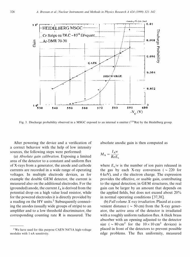
Fig. 3. Discharge probability observed in a MSGC exposed to an internal a emitter (220Rn) by the Heidelberg group.
2We have used for this purpose CAEN N471A high-voltagemodules with 1 nA sensitivity.
After powering the device and a verification ofa correct behavior with the help of low intensitysources, the following steps were performed:
(a) Absolute gain calibration. Exposing a limitedarea of the detector to a constant and uniform fluxof X-rays from a generator, the anode and cathodecurrents are recorded in a wide range of operatingvoltages. In multiple electrode devices, as forexample the double GEM detector, the current ismeasured also on the additional electrodes. For the(grounded) anode, the current I
Ais derived from the
potential drop on a high value load resistor, whilefor the powered electrodes it is directly provided bya reading on the HV units.2 Subsequently connect-ing the anodes (usually wide groups of strips) to anamplifier and to a low threshold discriminator, thecorresponding counting rate R is measured. The
absolute anodic gain is then computed as
MA"
IAw
ReE9
where E9/w is the number of ion pairs released in
the gas by each X-ray conversion (&220 for6 keV), and e the electron charge. The expressionprovides the effective, or usable gain, contributingto the signal detection; in GEM structures, the realgain can be larger by an amount that depends onthe applied fields, but does not exceed about 20%in normal operating conditions [37,38].
(b) Full volume X-ray irradiation. Placed at a con-venient distance (&50 cm) from the X-ray gener-ator, the active area of the detector is irradiatedwith a roughly uniform radiation flux. A thick brassabsorber with an opening adjusted to the detectorsize (&80 cm2 for the 10]10 cm2 devices) isplaced in front of the detectors to prevent possibleedge problems. The flux uniformity, measured
326 A. Bressan et al. /Nuclear Instruments and Methods in Physics Research A 424 (1999) 321—342

Fig. 4. Large signals (precursors) probability observed in a MSGC exposed to an external a source by the CERN group.
3 In the form of a mesh used for light enhancements in gasflame lamps (Welsbach mantle).
independently with the help of a small collimator, isbetter than 10% over the irradiated area; the valueof the flux is deduced from the measured currentsand the known absolute gain (see above). For eachsetting of the X-ray flux, the detectors’ operatingvoltage is increased progressively, recording theanodic current, until instabilities or discharges areencountered.
(c) Exposure to heavily ionizing particles. Openingthe gas flow to a bypass containing a thorium oxidecompound,3 the mixture is enriched with radon220Rn whose main decay mode (with 54 s lifetime)produces a particles of 6.4 MeV. Depending on thedistance from the generator, the gas flow and thedetector geometry, we record between a few anda few tens decays/s and cm3 of active volume. Thepulse height spectrum directly recorded at moder-ate gains on a wide group of anodes, without an
electronic amplifier to avoid saturation, is shown inFig. 6; the energy scale has been (approximately)calibrated by comparison with the charge detectedon soft X-rays. The spectrum has a peak around500 keV, and an exponentially decreasing tail ex-tending to several MeV.
In all measurements, the most delicate issue is thedefinition of the discharge limits and rates. As in-dicated in the previous section, several methodshave been used by different authors and a compari-son of results is not always straightforward. For thepresent study, we have adopted the rather extremeposition of defining a discharge as an event causingan overload of the current-limited power supplies,set at a threshold of about ten times the averagenormal current, with the consequent temporaryinhibition of the detected normal signals. To avoiddamages due to sustained discharges, a dead timeof several minutes has been built-in after each dis-charge before restoration of the voltages. Despiteits roughness, this definition of discharge is in factthe closest to represent the practical limits in the
A. Bressan et al. /Nuclear Instruments and Methods in Physics Research A 424 (1999) 321—342 327

Fig. 5. Gain (measured at low rates) as a function of cathode voltage of a MSGC without and with the added preamplification of a gaselectron multiplier. The histogram represents the distribution of discharge voltage for groups of anodes observed under simultaneousexposure to X-rays (&104 Hz mm~2) and to the internal a source.
use of a detector. To avoid distortions caused bythe power supply recovery time, and also possibledamages to the more delicate structures, themeasurement is suspended when the discharge rateexceeds a few counts per minute. We have verifiedthat this definition gives results virtually coincidingwith those obtained with the alternative method ofcounting pulses exceeding a pre-set large threshold,or precursors, typically an order of magnitudehigher than the largest normal signals.
In most detectors, we have observed a rathersharp transition from the condition of no dischargeto the onset of instabilities; with reference to Fig. 4,one may define as “discharge limit” the voltage justbelow the first non-zero count (580 V in the figure),and “maximum gain before discharge” the corre-sponding value of gain. In most plots, this value isindicated by a dashed vertical line. Note howeverthat, in view of the very low discharge rate oftenrecorded at the lowest voltages, these indicativevalues depend on the time allowed for each
measurement, and a complete discharge probabil-ity curve such as those shown is a more realisticrepresentation of the process.
5. Experimental results
Systematic measurements of discharge limits un-der high-flux X-ray exposure and internal a decayshave been performed with a collection of recentlydeveloped detectors; Table 1 provides schematicsand summary of parameters for the devices tested.Some of the detectors were built at CERN, otherswere provided by collaborating institutions, as in-dicated later in the text. Whilst we have attemptedto operate all detectors in similar conditions, some-times this was not possible or desirable; forexample, the active volume for some devices (e.g.the micro-dot) was considerably smaller, and thefilling gas (a mixture of argon and carbon dioxidefor all GEM-based devices) was changed to use
328 A. Bressan et al. /Nuclear Instruments and Methods in Physics Research A 424 (1999) 321—342

Fig. 6. Energy loss spectrum of an internal 220Rn a particles source, recorded with the micro-dot chamber.
4Produced by Alenia, Italy, and provided by IIHE ULB-VUB Brussels.
mixtures preferred by the developers of the micro-dot, micromegas and the advanced passivationMSGC. In general, a wider investigation on theeffect of the gas choice on the performance of thedetectors would be desirable; however, measure-ments with GEM in different mixtures (argon withcarbon dioxide, argon-DME and neon-DME, seelater) yielded essentially the same results. Also, tak-ing into account the previous discussions on thenon-uniformity of response, some variability in theresults may have been introduced by the unevenquality of the detectors themselves. In comparingthe measurements, one should consent to a spread,within the same class of devices, of perhaps a factorof two in the observed values of limiting gain.Nevertheless we consider that the major con-clusions of this study are general enough to be onlymarginally affected by this variability.
5.1. Micro-strip gas chamber: standard
Measurements with this device have alreadybeen reported, and have not been repeated;
Figs. 1—4 provide a summary of previous results.One should note that a discharge in the delicateMSGC structures often results in permanent dam-age, affecting the performances of the detector; thisis particularly true if a low melting point metal suchas gold is used for the strips. The outcome of themeasurements depends, more than with any other,on the previous history of the device.
5.2. Micro-strip gas chamber: advanced passivation
A technology for protecting the cathode stripsedges with a thin polymide coating has been re-cently developed, with the aim of increasing thevoltage required for the onset of discharges [20].We have tested a 10]10 cm2 MSGC plate with theso-called advanced passivation, manufactured withgold strips on a support coated with a thin layerof electron conducting glass.4 The operating
A. Bressan et al. /Nuclear Instruments and Methods in Physics Research A 424 (1999) 321—342 329
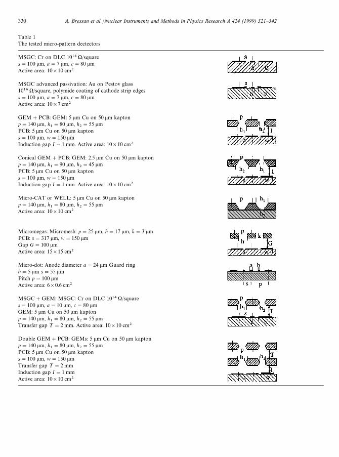
Table 1The tested micro-pattern dectectors
MSGC: Cr on DLC 1014 )/squares"100 lm, a"7 lm, c"80 lmActive area: 10]10 cm2
MSGC advanced passivation: Au on Pestov glass1016 )/square, polymide coating of cathode strip edgess"100 lm, a"7 lm, c"80 lmActive area: 10]7 cm2
GEM#PCB: GEM: 5 lm Cu on 50 lm kaptonp"140 lm, h
1"80 lm, h
2"55 lm
PCB: 5 lm Cu on 50 lm kaptons"100 lm, w"150 lmInduction gap I"1 mm. Active area: 10]10 cm2
Conical GEM#PCB: GEM: 2.5 lm Cu on 50 lm kaptonp"140 lm, h
1"90 lm, h
2"45 lm
PCB: 5 lm Cu on 50 lm kaptons"100 lm, w"150 lmInduction gap I"1 mm. Active area: 10]10 cm2
Micro-CAT or WELL: 5 lm Cu on 50 lm kaptonp"140 lm, h
1"80 lm, h
2"55 lm
Active area: 10]10 cm2
Micromegas: Micromesh: p"25 lm, h"17 lm, k"3 lmPCB: s"317 lm, w"150 lmGap G"100 lmActive area: 15]15 cm2
Micro-dot: Anode diameter a"24 lm Guard ringb"5 lm s"55 lmPitch p"100 lmActive area: 6]0.6 cm2
MSGC#GEM: MSGC: Cr on DLC 1014 )/squares"100 lm, a"10 lm, c"80 lmGEM: 5 lm Cu on 50 lm kaptonp"140 lm, h
1"80 lm, h
2"55 lm
Transfer gap ¹"2 mm. Active area: 10]10 cm2
Double GEM#PCB: GEMs: 5 lm Cu on 50 lm kaptonp"140 lm, h
1"80 lm, h
2"55 lm
PCB: 5 lm Cu on 50 lm kaptons"100 lm, w"150 lmTransfer gap ¹"2 mmInduction gap I"1 mmActive area: 10]10 cm2
330 A. Bressan et al. /Nuclear Instruments and Methods in Physics Research A 424 (1999) 321—342
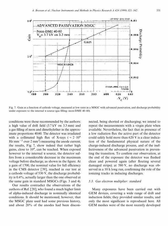
Fig. 7. Gain as a function of cathode voltage, measured at low rates in a MSGC with advanced passivation, and discharge probabilityunder exposure to the internal a source (gas filling: neon-DME 40—60).
conditions were those recommended by the authors:a high value of drift field (3.7 kV on 3.3 mm) anda gas filling of neon and dimethylether in the approx-imate proportions 40:60. The detector was irradiatedwith a collimated high flux of X-rays (&2 )104Hz mm~2 over 2 mm2) measuring the anode current;the results, Fig. 7, show indeed that rather highgains, close to 104, can be reached. When exposedhowever to the internal a source, the detector suf-fers from a considerable decrease in the maximumvoltage before discharge, as shown in the figure. Ata gain of 1700, the nominal value for full efficiencyin the CMS detector [39], reached in our test ata cathode voltage of 530 V, the discharge probabil-ity is 0.4%, actually larger than the one observed atthe same gain in standard MSGCs (Figs. 3 and 4).
Our results contradict the observations of theauthors of Ref. [20], who found a much higher limitof alpha-induced discharge in nominally identicalconditions. It should be mentioned, however, thatthe MSGC plate used had some previous history,and about 20% of the anodes had been discon-
nected, being shorted or discharging; we intend torepeat the measurements with a virgin plate whenavailable. Nevertheless, the fact that in presence ofa low radiation flux the active part of the detectorcould safely hold more than 620 V is a clear indica-tion of the fundamental physical nature of thecharge-induced discharge process, and of the inef-fectiveness of the advanced passivation in preven-ting the transition. To confirm our observation, atthe end of the exposure the detector was flushedclean and powered again (after floating severaldamaged strips); at 580 V, no discharge was ob-served in a 10 h long run, confirming the role of theionizing tracks in inducing discharges.
5.3. Gas electron multiplier: standard
Many exposures have been carried out withGEM devices, covering a wide range of drift andinduction fields; they provided similar results, andonly the most significant is reproduced here. AllGEM meshes were of the most recently developed
A. Bressan et al. /Nuclear Instruments and Methods in Physics Research A 424 (1999) 321—342 331

Fig. 8. Current as a function of voltage in the GEM detector with printed circuit readout, at increasing X-ray fluxes. For the lowestcurve, the value of gain is given on the right scale. The dashed curve represents the maximum sustainable voltage before discharge.
high-gain model, produced with a double maskprocessing and having quasi-cylindrical holes80 lm in diameter at the metal sides [37,40]. Asa filling gas we have used argon—CO
2in the
70:30 vol.%, a convenient mixture for the use inlarge detectors, even though certainly not the bestfor obtaining high gains [32]. Fig. 8 shows, asa function of GEM voltage and at increasing rates,the current measured on a group of anode strips(covering 100]5 mm2) whilst irradiating the wholeactive area of the detector with X-rays. The scale onthe right provides, for the lowest curve, the corre-sponding values of effective gain. The gain curvesare exponential and parallel within the errors, dem-onstrating the excellent rate capability of the GEMdetector. The last point on each line corresponds tothe voltage value reached just before discharge, andthe dashed curve represents the boundary for stableoperation. The maximum stable gain, around 8000at low rates, is reduced by a factor of two at a flux of104 Hz mm~2 over the whole active area.
In Fig. 9, one can see the effect of adding theinternal a emitter; gain and discharge probabilityare given as a function of GEM voltage. Realizedwith a higher field in the induction gap, the gaincurve is slightly shifted, compared to the previous,to lower voltages, due to the increased collectionefficiency [37]. Stable up to a gain of about 1500,the detector exhibits a low but quickly increasingrate of discharges above that value.
Several attempts have been made to improve themaximum gain with a different choice of the gasmixture, having a priori better quenching proper-ties than Ar—CO
2. While moderately larger gains
could indeed be obtained, for example in DME-rich mixtures, the gain at discharge on exposure toheavily ionizing tracks appears to be almost invari-ant. As an example, Fig. 10 shows the resultsobtained with neon—DME, a mixture reported topermit high gains in MSGCs due to a strongsuppression of photon emission in the avalanches[41]. As before, a fast increasing a-induced
332 A. Bressan et al. /Nuclear Instruments and Methods in Physics Research A 424 (1999) 321—342

Fig. 9. Effective gain and discharge probability on the internal a source obtained with the GEM detector with an argon—CO2gas filling.
discharge probability at gains above 1500 isobserved.
5.4. Gas electron multiplier: conical
The characteristics of GEM devices with conicalholes, conveniently manufactured with a single-mask processing, have been described before [40];because of peculiarities in their performances (amore pronounced charging-up, and limitations tothe values of external fields) they have not yet beenused extensively.
We have employed for this measurement a gain-limited early prototype, with rather wide holediameters of 90 and 45 lm on the two sides respec-tively. Fig. 11 summarizes the behavior of a conicalGEM with PCB readout, mounted in two config-urations: electrons drifting from the narrow to thewide side (N-'W) and the reverse (W-'N). Asexpected for this design, the maximum gain thatcan be reached at low irradiation rates is moderate.The internal a emitter reduces this gain further,
with a slight preference for the N-'W configura-tion (gain 2000 as against 1000 before discharge).Because of the different field configuration andcharge sharing in the two configurations, the realgains at discharge (as against the effective onesshown in the figure) are actually rather close.
5.5. Micro-CA¹ (or ¼E¸¸) detector
Recently introduced, the Micro-CAT [8], micro-groove [9] and WELL [10] detectors are in factvariants of the original CAT device [4], realizedwith the more sophisticated etching technologiesdeveloped for GEM. We have manufactured aWELL device replacing the open holes on the backside of a standard GEM with collecting strips con-stituting anodes for the multiplying structure. Theresponse of the detector under a irradiation isshown in Fig. 12; the maximum operating voltagebefore discharge corresponds to a gain of 2000.Note that in this device, and unlike the standardGEM detector, all the avalanche charge is
A. Bressan et al. /Nuclear Instruments and Methods in Physics Research A 424 (1999) 321—342 333

Fig. 10. Effective gain and discharge probability with the internal a source observed with the GEM detector in neon—DME.
5Manufactured by EURYSIS Measures, France and pro-vided by ULB Bruxelles.
collected, and the effective and real gains coincide;nevertheless, because of the ballistic deficit intrinsicin devices operated in the avalanche mode, thesignal detected by a fast amplifier on the anodes isactually smaller.
5.6. Micromegas
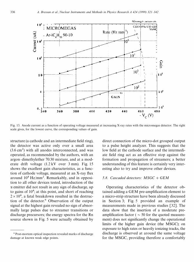
To realize this measurement we have obtaineda commercial device already extensively tested5. Inorder to get consistent results, the filling gas wasargon—isobutane in the 90:10 vol.%, as recommen-ded by the providers. Fig. 13 summarizes the re-sults of the exposure to an increasing X-ray flux,and Fig. 14 shows the response to the internala emitter. All X-ray measurements were realizedirradiating most of the active area, with the excep-tion of the highest rate where the exposed area was
reduced to 64 mm2 to elude problems due to thepotential drop on protection resistors. In agree-ment with the original observations [6], very highgains could be achieved, even though adecrease inmaximum gain is observed at the highest rates.
Remarkably however, and much as in all pre-viously described devices, introduction of the220Rn emitter reduced the maximum gain beforedischarge at a value around between 2500 and3000. Note that, while the mechanical structure ofthe detector is impervious to damage due to dis-charges, this may not be the case of the sensitiveelectronics used for the readout of signals on theanode strips, particularly in view of the largecapacitance of the detector.
5.7. Micro-dot chamber
The micro-dot tested was a small size standarddevice developed and provided by the Liverpoolgroup [3,42]. Consisting of individual anodic dots,24 lm in diameter, centered in a double annular
334 A. Bressan et al. /Nuclear Instruments and Methods in Physics Research A 424 (1999) 321—342

Fig. 11. Effective gain and discharge probability with the internal a source for two configurations of the conical GEM detector.
Fig. 12. Effective gain and discharge probability with the internal a source for the micro-CAT or WELL detector.
A. Bressan et al. /Nuclear Instruments and Methods in Physics Research A 424 (1999) 321—342 335
6Post-mortem optical inspection revealed marks of dischargedamage at known weak edge points.
Fig. 13. Anode current as a function of operating voltage measured at increasing X-ray rates with the micromegas detector. The rightscale gives, for the lowest curve, the corresponding values of gain.
structure (a cathode and an intermediate field ring),the detector was active only over a small area(3.6 cm2) with all anodes interconnected, and wasoperated, as recommended by the authors, with anargon—dimethylether 70:30 mixture, and at a mod-erate drift voltage (1.2 kV over 3 mm). Fig. 15shows the excellent gain characteristics, as a func-tion of cathode voltage, measured at an X-ray fluxaround 104 Hz/mm2. Remarkably, and in opposi-tion to all other devices tested, introduction of thea emitter did not result in any sign of discharge, upto gains of 104; at this point, and short of reaching2]104, a fatal breakdown resulted in the destruc-tion of the detector.6 Observation of the outputsignal at the highest gain revealed no sign of abnor-mally large pulses due to streamer transitions ordischarge precursors; the energy spectra for the Rnsource shown in Fig. 5 were actually obtained by
direct connection of the micro-dot grouped outputto a pulse height analyzer. This suggests that thelow field at the cathode surface and the intermedi-ate field ring act as an effective stop against theformation and propagation of streamers; a betterunderstanding of this feature is certainly very inter-esting also to try and improve other devices.
5.8. Cascaded detectors: MSGC#GEM
Operating characteristics of the detector ob-tained adding a GEM pre-amplification element toa micro-strip structure have been already discussedin Section 3; Fig. 5 provided an example ofmeasurements made in previous studies [32]. Thedata show that the insertion of a moderate pre-amplification factor (&50 for the quoted measure-ment) does not significantly change the operationallimits of the higher gain device (the MSGC); onexposure to high rates or heavily ionizing tracks, thedischarge is observed at around the same voltagefor the MSGC, providing therefore a comfortably
336 A. Bressan et al. /Nuclear Instruments and Methods in Physics Research A 424 (1999) 321—342

Fig. 14. Gain and discharge probability with the internal a source in the micromegas detector.
Fig. 15. Gain as a function of voltage in the micro-dot detector. No effect of the internal a source has been observed up to a gain of 104.
A. Bressan et al. /Nuclear Instruments and Methods in Physics Research A 424 (1999) 321—342 337

Fig. 16. High rate behavior of the double GEM detector, irradiated over &3 mm2 with an increasing X-ray flux. The anodic current isgiven as a function of voltage in the second GEM, with the first kept constant.
higher safety margin. Several groups have confirmedthese findings [22,43—45], and the MSGC#GEMdevice has been adopted for the HERA-B innertracker after an extensive campaign of experimentalexposures to different beam conditions [17,46].
5.9. Cascaded detectors: double GEM#PCB
The combination of two gas electron multipliersin cascade permits very large stable gains to beachieved; in good approximation, and taking intoaccount the (small) transfer losses between the twoelements, the overall gain is the product of the two[47,48]. With a double-GEM device having thegeometry described in Table 1, we have measuredat increasing X-ray fluxes the current on a group ofanodes as a function of the voltage difference ap-plied to the two GEMs. Due to the high values ofgain and flux, and to limit the voltage drop on theprotection resistors, for the higher fluxes the irra-
diated area had to be reduced to a few mm2, andthe data correspondingly normalized. As shown inFig. 16, the current measured on the charge-collect-ing anodes increases exponentially with the voltageapplied to the second GEM, for fixed value of thefirst, and curves at increasing rates are parallelwithin the measurement errors, demonstrating theabsence of surface or space charge distortions.Fig. 17 provides, for the highest irradiation rate(5]105 Hz mm~2) the effective gain as a functionof voltage applied to the multipliers; a gain wellabove 104 can be reached in a wide range of poten-tials, with a maximum up to 105. The dashed curvein the figure represents the discharge limit; consid-ering the first GEM to act only as a variable chargeinjector, the trend of withstanding larger gains (lar-ger amount of charge) when the second multiplieroperates at lower potentials supports our presump-tion of a voltage dependence of the discharge limit.We have repeated the gain measurement with expo-sure of the detector to the internal a source; in this
338 A. Bressan et al. /Nuclear Instruments and Methods in Physics Research A 424 (1999) 321—342

Fig. 17. Effective gain of the double GEM detector at high X-ray flux (5]105 Hz mm~2) as a function of voltage on the second GEM,for several values of the first. The dashed curve shows the maximum gain envelope.
case, only the upper boundary of stability beforedischarge has been recorded (Fig. 18). Themaximum gain is again reduced by an amount thatdepends on the gain sharing between the two multi-pliers; the optimum is an operation with closevalues of the voltage difference. For large offsetsbetween the two, the characteristic limitations ofa single GEM are found.
6. Conclusions and summary
This work describes the results of systematicmeasurements obtained with an exhaustive list ofrecently developed fast gaseous detectors, in orderto assess their performances and reliability in theharsh operating conditions that will prevail in ex-perimental set-ups at high luminosity colliders,namely the simultaneous presence of a high flux ofrelativistic charged particles and of rarer but heav-ily ionizing tracks. The general trend emergingfrom the study of single-stage devices is that, al-
though they differ in the maximum gain reached ina low radiation environment, the difference tends tovanish with an exposure to a high flux of X-raysand to heavily ionizing tracks, emulated in thisstudy by an internal alpha emitter added to the gasflow. In these conditions, a non-negligible probabil-ity of a transition from proportional avalanche tostreamer followed by a discharge is observed atproportional gains between one and two thousand.A remarkable exception in this class of devices, themicro-dot detector seems to withstand the highestgains in such conditions.
Taking into account the measured ionizationloss distribution (Fig. 6), it can be inferred that thetransition begins to occur when the average ava-lanche size exceeds a 2—3]107 electrons, close tothe so-called Raether limit. The low dischargeprobability at the onset of the process, below onepercent of the recorded a particles countingrate, suggests that the transition is an outcome ofstatistical fluctuations on the avalanche formation,leading from time to time to what the authors of
A. Bressan et al. /Nuclear Instruments and Methods in Physics Research A 424 (1999) 321—342 339
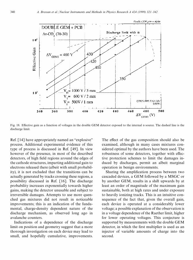
Fig. 18. Effective gain as a function of voltages in the double GEM detector exposed to the internal a source. The dashed line is thedischarge limit.
Ref. [14] have appropriately named an “explosive”process. Additional experimental evidence of thistype of process is discussed in Ref. [49]. In viewhowever of the presence, in most of the describeddetectors, of high field regions around the edges ofthe cathode structures, imparting additional gain toelectrons released there (albeit with small probabil-ity), it is not excluded that the transitions can beactually generated by tracks crossing these regions, apossibility discussed in Ref. [16]. The dischargeprobability increases exponentially towards highergains, making the detector unusable and subject toirreversible damages. Attempts to use more quen-ched gas mixtures did not result in noticeableimprovements; this is an indication of the funda-mental, charge-density dependent nature of thedischarge mechanism, as observed long ago inavalanche counters.
Indications of a dependence of the dischargelimit on position and geometry suggest that a morethorough investigation on each device may lead tosmall, and hopefully cumulative, improvements.
The effect of the gas composition should also beexamined, although in many cases mixtures con-sidered optimal by the authors have been used. Therobustness of some detectors, together with effec-tive protection schemes to limit the damages in-duced by discharges, permit an albeit marginaloperation in benign environments.
Sharing the amplification process between twocascaded devices, a GEM followed by a MSGC orby another GEM, results in a shift upwards by atleast an order of magnitude of the maximum gainsustainable, both at high rates and under exposureto heavily ionizing tracks. This is an intuitive con-sequence of the fact that, given the overall gain,each device is operated at a considerably lowervoltage; a possible explanation of the observation isin a voltage dependence of the Raether limit, higherfor lower operating voltages. This conjecture issupported by measurements with the double GEMdetector, in which the first multiplier is used as aninjector of variable amounts of charge into thesecond.
340 A. Bressan et al. /Nuclear Instruments and Methods in Physics Research A 424 (1999) 321—342

An alternative explanation for the increased limitof divergence has been suggested by some authors(see Ref. [22] and references therein) as being a con-sequence of the reduction of charge density in theavalanche induced by the additional spread due todiffusion in the double devices. Recent measure-ments of cluster size in single and double GEMdetectors however do not seem to support thistheory, the average avalanche size increasing onlyby a small amount (20%) by the additional multi-plication [48]. More work on the subject is certain-ly required.
The comfortable margin between the gainneeded for full efficiency detection of fast particles(&2000) and the maximum gain before dischargein the double devices ('104) suggest that this re-cently introduced family of detectors is the mostsuited for reliable use in high rate experimentalset-ups, with simultaneous presence of a high fluxof relativistic charged particles to be detected, andof a considerable background of unwanted, highlyionizing events, as for example proton knock-off byneutrons conversions and production of nuclearfragments.
It should be mentioned that simulation studiesshow that alpha particles, as used in this work, givean optimistic view of the conditions to be met atLHC [50]. Under these circumstances, and pend-ing a realistic test of the devices at the new collider,it is suggested that more experimental work anda careful analysis to the operational safety marginsshould be made before the adoption of a detectorgeometry for the experiments.
Acknowledgements
Two of the detectors used in this work, micro-megas and the advanced passivation MSGC, havebeen provided by W. Van Doninck and S. Taver-nier (IIHE ULB-VUB Bruxelles); their contribu-tion is here acknowledged. The technology formanufacturing the GEM electrodes has beendeveloped by A. Gandi and R. De Oliveira(CERN-EST-MT). The detectors were assembledby M. Delattre and M. Van Stenis in the EP-TA1group led by A. Placci, whose continuing supportfor our work is here acknowledged. The wire bond-
ing for the connection of the electrodes to thereadout boards have been made by O. Runolffsonand K. Muhlemann (CERN-EP-OPAL).
References
[1] A. Oed, Nucl. Instr. and Meth. A 263 (1988) 351.[2] F. Angelini, R. Bellazzini, A. Brez, M.M. Massai, R. Raffo,
G. Spandre, M.A. Spezziga, Nucl. Instr. and Meth. A 335(1993) 69.
[3] S.F. Biagi, T.J. Jones, Nucl. Instr. and Meth. A 361 (1995)72.
[4] F. Bartol, M. Bordessoule, G. Chaplier, M. Lemonnier, S.Megtert, J. Phys. III (France) 6 (1996) 337.
[5] V. Chorowicz, J.-F. Clergeau, D. Contardo, R. Harout-unian, L. Mirabito, S. Muanza, G. Smadja, Nucl. Instr.and Meth. A 401 (1997) 238.
[6] I. Giomataris, P. Rebourgeaud, J.P. Robert, G. Charpak,Nucl. Instr. and Meth. A 376 (1996) 29.
[7] F. Sauli, Nucl. Instr. and Meth. A 386 (1997) 531.[8] A. Savestrani, H.J. Besch, M. Junk, W. Meissner, N. Sauer,
R. Stiehler, A.H. Walenta, R.H. Menk, Study and applica-tions of hole structures as gas gain devices for two-dimen-sional high rate X-ray detectors, Nucl. Instr. and Meth.,1998, submitted.
[9] R. Bellazzini, M. Bozzo, A. Brez, G. Gariano, L. Lan-tronico, N. Lumb, A. Papanestis, G. Spandre, M.M. Mass-ai, R. Raffo, M.A. Spezziga, Nucl. Instr. and Meth. A,(1998) in press.
[10] R. Bellazzini, M. Bozzo, A. Brez, G. Gariano, L. Lan-tronico, N. Lumb, A. Papanestis, G. Spandre, M.M. Mass-ai, R. Raffo, M.A. Spezziga, Nucl. Instr. and Meth. A 423(1999) 125.
[11] F. Sauli, Nucl. Phys. B 61 B (1998) 236.[12] F. Sauli, Nucl. Instr. and Meth. A 419 (1998) 189.[13] T. Beckers, R. Bouclier, C. Garabatos, G. Million, F. Sauli,
L. Shekhtman, Nucl. Instr. and Meth. A 346 (1994) 95.[14] V. Peskov, B.D. Ramsey, P. Fonte, Nucl. Instr. and Meth.
A 392 (1997) 89.[15] V. Peskov, B.D. Ramsey, J.J. Kolodziejczak, P. Fonte,
Nucl. Instr. and Meth. A 397 (1997) 243.[16] R. Bouclier, M. Capeans, C. Garabatos, G. Manzin, G.
Million, L. Ropelewski, F. Sauli, T. Temmel, L. Shekht-man, V. Nagaslaev, Y. Pestov, A. Kuleshov, Nucl. Instr.and Meth. A 365 (1995) 65.
[17] B. Schmidt, Nucl. Instr. and Meth. A 419 (1998) 230.[18] A. Barr et al., Nucl. Instr. and Meth. A 403 (1998) 31.[19] B. Boimska, R. Bouclier, M. Capeans, S. Claes,
W. Dominik, M. Hoch, G. Million, L. Ropelewski,F. Sauli, A. Sharma, L. Shekhtman, W.V. Doninck,L.V. Lancker, Nucl. Phys. B 61 B (1998) 498.
[20] R. Bellazzini, A. Brez, L. Lantronico, N. Lumb,G. Spandre, Nucl. Instr. and Meth. A 398 (1998) 426.
[21] V. Peskov, B.D. Ramsey, P. Fonte, IEEE Trans. Nucl. Sci.NS-45 (1998) 244.
A. Bressan et al. /Nuclear Instruments and Methods in Physics Research A 424 (1999) 321—342 341
[22] P. Fonte, V. Peskov, B.D. Ramsey, Nucl. Instr. and Meth.A 419 (1998) 405.
[23] H.S. Cho, W.S. Hong, N. Palaio, J. Kadyk, K.B. Luk,V. Perez-Mendez, K.S. Joo, J. Vujic, Nucl. Phys. B 61B (1998) 258.
[24] L.B. Loeb, Basic Processes in Gaseous Electronics, Uni-versity of California Press, Berkeley, CA, 1961.
[25] H. Raether, Electron Avalanches and Breakdown inGases, Butterworth, London, 1964.
[26] J.A. Rees, Electrical Breakdown in Gases, MacMillanPress, London, 1973.
[27] J.M. Meek, Phys. Rev. 57 (1940) 722.[28] P. Fonte, V. Peskov, F. Sauli, Nucl. Instr. and Meth. A 305
(1991) 91.[29] P. Fonte, IEEE Trans. Nucl. Sci. NS-43 (1996) 2135.[30] E. Iarocci, Nucl. Instr. and Meth. 217 (1983).[31] B. Boimska, R. Bouclier, M. Capeans, W. Dominik, M.
Hoch, G. Million, L. Ropelewski, F. Sauli, A. Sharma,CMS Tracking Note TN/97-020, 1997.
[32] R. Bouclier, W. Dominik, M. Hoch, J.C. Labbe, G. Mil-lion, L. Ropelewski, F. Sauli, A. Sharma, G. Manzin, Nucl.Instr. and Meth. A 396 (1997) 50.
[33] R. Bouclier, M. Capeans, G. Million, L. Ropelewski, F.Sauli, T. Temmel, R.A. Cooke, S. Donnel, S.A. Sastri, N.Sonderer, Nucl. Instr. and Meth. A 369 (1996) 328—331.
[34] P. Fonte, V. Peskov, B.D. Ramsey, Which gaseous de-tector is the best at high rates? Int. Report, 1998.
[35] Y. Ivanouchenkov, P. Fonte, V. Peskov, B.D. Ramsey,Nucl. Instr. and Meth. A 422 (1999) 300.
[36] R. Bouclier, M. Capeans, A. Di Mauro, M. Hoch, L.Ropelewski, F. Sauli, A. Sharma, L. Shekhtman, CERNCMS-TN/96-018, 1996.
[37] J. Benlloch, A. Bressan, M. Capeans, M. Gruwe, M. Hoch,J.C. Labbe, A. Placci, L. Ropelewski, F. Sauli, Nucl. Instr.and Meth. A 419 (1998) 410.
[38] R. Bellazzini, A. Brez, G. Gariano, L. Latronico, N. Lumb,G. Spandre, M.M. Massai, R. Raffo, M.A. Spezziga, Nucl.Instr. and Meth., 1998, submitted.
[39] D. Abbaneo et al., Nucl. Instr. and Meth. A 409 (1998)37.
[40] J. Benlloch, A. Bressan, C. Buttner, M. Capeans, M.Gruwe, M. Hoch, J.C. Labbe, A. Placci, L. Ropelewski, F.Sauli, A. Sharma, R. Veenhof, IEEE Trans. Nucl. Sci.NS-45 (1998) 234.
[41] F. Angelini, R. Bellazzini, A. Brez, M.M. Massai, R. Raffo,G. Spandre, M.A. Spezziga, Nucl. Instr. and Meth. A 382(1996) 461.
[42] S. Biagi, T.J. Bowcock, D. Duxbury, E. Gabathuler, Nucl.Phys. B 61 B (1998) 311.
[43] Y. Benhammou, J.M. Brom, J.C. Fontaine, D. Huss, F.Jeanneau, A. Lounis, I. Ripp-Baudot, A. Zghiche, IReS98-13, 1998.
[44] W. Van Doninck, C. Vandervelde, F. Udo, O. Bouhali, P.Vanlaer, V. Zhukov, GEM and MSGC: Results obtainedin the cosmic hodoscope, Wire Chamber Conf. Vienna,22—26 February, 1998; Nucl. Instr. and Meth., 1998,submitted.
[45] W. Beaumont, T. Beckers, J. DeTroy, V. Van Dyck, O.Bouhali, F. Udo, C. VanderVelde, W. Van Doninck, P.Vanlaer, V. Zhukov, Nucl. Instr. and Meth. A 419 (1998)394.
[46] M.G. Ziegler, Untersuchungen von Detektorprototypenfur das innere Spurkammersystem des HERA-B Experi-mentes, Thesis, Univ. Heidelberg, 1998.
[47] C. Buttner, M. Capeans, W. Dominik, M. Hoch, J.C.Labbe, G. Manzin, G. Million, L. Ropelewski, F. Sauli, A.Sharma, Nucl. Instr. and Meth. A 409 (1998) 79.
[48] A. Bressan, J.C. Labbe, P. Pagano, L. Ropelewski, F. Sauli,Beam tests of the gas electron multiplier, Nucl. Instr. andMeth. A, (1999) in press.
[49] I. Ivaniouchenkov, P. Fonte, V. Peskov, R. Ferreira-Mar-ques, A. Policarpo, IEEE Trans. Nucl. Sci. NS-45 (1998)258.
[50] M. Huhtinen, Factors to scale highly ionizing particlerates in MSGC irradiation tests to the LHC radiationenvironment, CMS Note 1997/073, 1997.
342 A. Bressan et al. /Nuclear Instruments and Methods in Physics Research A 424 (1999) 321—342