high pressure gear pumps kp 1 - process pump sales€¦ · discharge flow refer to charts page 4...
TRANSCRIPT

High Pressure Gear Pumps KP 1

General Characteristics
Mounting Flange and Foot-TypePipe Connection Flange Type,
G-GAS thread on requestDirection of Rotation Clockwise or AnticlockwiseWeight refer to Dimensional SheetsFitting Position OptionalPermissible Ambient ϑu min = – 20 °CTemperature Range ϑu max = + 60 °C
Operating Characteristics
Operating PressuresInlet Port pe min = – 0.4 bar (Vacuum)
pe max = 2 barShort Time pe max = 5 bar Outlet Port pmax = see technical Data
Fluid Temperature Range ϑm max = 90 °C for NBR-RotaryShaft Lip-Type Seal100 °C for FPM-RotaryShaft Lip-Type Seal
Viscosity Range νmin = 10 mm2/sνmax = 600 mm2/s
Recommended Class 19/16 acc. to ISO /DIS 4406Oil Cleanliness ➧➧ Class 10 acc. to NAS 1638Recommended Filtration Filter with Filtration Quotient
β25 ≥ 75 for … 300 barβ40 ≥ 75 for … 100 bar
RecommendedViscosity Range ν = 30 … 45 mm2/sDischarge Flow refer to Charts Page 4Input Power refer to Charts Page 4Hydraulic Fluids Mineral Oil acc. to DIN 51524/25
Engine Oil acc. to DIN 51511Bio-oils of type „HEES“, can beused up to 70 °C, max. pressuremust be reduced minus 20% (use only on request)
Materials
Housing Aluminium-Alloy, Cast Iron on request
Bearing Double-Gland Bearing with Multi-component Plane Bearing Bushes
Journals and Gears Case Hardening Steel acc. to DIN 17210 Surface Hardened andGround
Seals 1 NBR Rotary ShaftLip-Type Seal ϑ ≤ 90 °C 2 FPM Rotary ShaftLip-Type Seal ϑ ≤ 100 °C
Configuration of High Pressure Gear Pump KP 1
KRACHT GmbH · Postbox 1420/1440 · D-58774 Werdohl · Phone 0049 (23 92) 935-0 · Fax 0049 (23 92) 935 209 · Internet: www.kracht-hydraulik.de · e-mail: [email protected]
Description
Accordingly to its configuration – the Design Principle is illustra-ted by the Sectional Figure – the Kracht External Gear-Type PumpSeries KP1 is to be classified into the category of the so-calledGland-Type Bearing Pumps.All essential functional parts as the gearing and the gland bea-rings are located in an aluminium housing (cast iron on requestpossible) manufactured of a high strength extrusion alloy whichare closed on each side by an end cover or by a flange mountingcover respectively.The gearing of case hardening steel in surface hardened conditionconsists of the driving shaft pinion and the driven shaft pinion.Highest manufacturing quality is assured by grinding and honingof the tooth flanks. The surfaces of the journals are superfinished.An important reduction of the type dependent deviation of thevolumetric flow and of the pressure pulsation incident thereto wasachieved on the basis of the great teeth number (z = 13) and ofthe specially shaped teeth. The gland bearings located on bothsides of the gearing carry the journals in heavyduty multicompo-nent plane bearing bushes and contain additionally those sealingelements which serve for the pressure field sealing to compensatethe axial clearance.All sealings are optionally available in Perbunan (NBR) or Viton(FPM) compounds in dependence on the different applicationsconcerning the temperature ranges and/or medium requirements.If required the pumps can be supplied with a Pressure ReliefValve-Type DBD... – directly attached to the pump or with specialvalve arrangements assembled onto the pump instead of the endcover. Manifold Pump Combinations are available as well.
Special Note
1. External Loads Loads acting on the drive shaft end from outside impair thefunctions of the doublegland bearing.Radial loads can be absorbed in dependence on the extent andthe direction of the loads. Axial Ioads are NOT permissible. Toabsorb outer loads only those pump types shall be used whichare equipped with an Outboard Bearing.
2. Direction of Rotation Regarding the direction of rotation basically the followingapplies provided the view is directed toward the drive shaft end:Drive shaft end rotating clockwise: Flow direction from left to right. Drive shaft end rotating anticlockwise:Flow direction from right to left.
1 Housing2 Gearing3 Drive Shaft End4 Flange Mounting Cover5 End Cover6 Double-Gland Bearing with
special plane bearing bushes7 Rotary Shaft Lip-Type Seals8 Pressure Field Sealing for
axial clearance compensation9 Sealing of the Housing
37185 4269
Technical Data
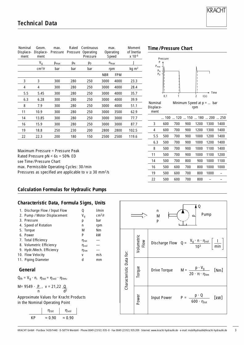
Nominal Geom. max. Rated Continuous max. MomentDisplace- Displace- Pressure Pressure Operating Operating of Inertia
ment ment Pressure Speed x 10-6
Vg pmax pN pD nmax J
cm3/r bar bar bar rpm kg m2
NBR FPM
3 3 300 280 250 3000 4000 23.3
4 4 300 280 250 3000 4000 28.4
5.5 5.45 300 280 250 3000 4000 35.7
6.3 6.28 300 280 250 3000 4000 39.9
8 7.9 300 280 250 3000 4000 51.1
11 10.9 300 280 250 3000 3500 62.9
14 13.85 300 280 250 3000 3000 77.7
16 15.9 300 280 250 3000 3000 87.7
19 18.8 250 230 200 2800 2800 102.5
22 22.3 200 180 150 2500 2500 119.6
Nominal Minimum Speed at p = … barDisplace- rpm
ment
…100 …120 …150 …180 …200 …250
3 600 700 900 1200 1300 1400
4 600 700 900 1200 1300 1400
5.5 500 700 900 1000 1200 1400
6.3 500 700 900 1000 1200 1400
8 500 700 900 1000 1100 1400
11 500 700 900 1000 1100 1200
14 500 700 800 900 1000 1100
16 500 600 700 800 1000 1000
19 500 600 700 800 1000 –
22 500 600 700 800 – –
Time / Pressure Chart
Calculation Formulas for Hydraulic Pumps
Maximum Pressure = Pressure PeakRated Pressure pN < 6s = 50% EDsee Time / Pressure Chartmax. Permissible Operating Cycles: 30/ minPressures as specified are applicable to ν ≥ 30 mm2/s
Characteristic Data, Formula Signs, Units1. Discharge Flow / Input Flow Q l/min2. Pump / Motor Displacement Vg cm3/r3. Pressure p bar4. Speed of Rotation n rpm5. Torque M Nm6. Power P kW7. Total Efficiency ηη tot —8. Volumetric Efficiency ηη vol —9. Hydr./Mech. Efficiency ηη hm —
10. Flow Velocity v m/s11. Piping Diameter d mm
General
Qth = Vg · n, ηη tot = ηη vol · ηη hm,
M= 9549 · P , v = 21,22 Q n d2
Approximate Values for Kracht Products in the Nominal Operating Point
ηη tot ηη vol
KP ≈ 0.90 ≈ 0.90
Char
acte
ristic
Dat
a fo
r:
Pow
erTo
rque
Volu
met
ric
Flow Discharge Flow Q = Vg · n · ηvol
103l
min
Drive Torque M = p · Vg
20 · π · ηhm[Nm]
Input Power P = p · Q 600 · η tot
[kW]
Q
p
nMP
PPressure
Pmax
PNPD
0,1 1 2 t (s)Time
Pump
KRACHT GmbH · Postbox 1420/1440 · D-58774 Werdohl · Phone 0049 (23 92) 935-0 · Fax 0049 (23 92) 935 209 · Internet: www.kracht-hydraulik.de · e-mail: [email protected] 3
KRACHT GmbH · Postbox 1420/1440 · D-58774 Werdohl · Phone 0049 (23 92) 935-0 · Fax 0049 (23 92) 935 209 · Internet: www.kracht-hydraulik.de · e-mail: [email protected]
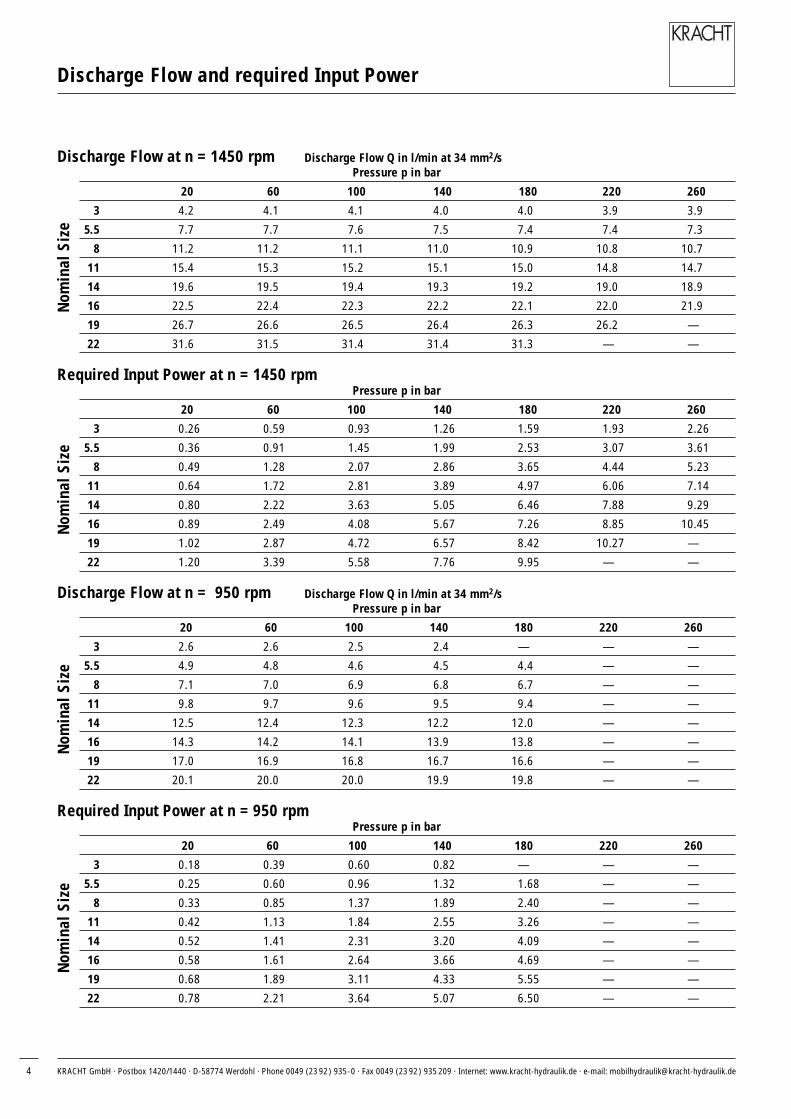
Discharge Flow and required Input Power
Discharge Flow at n = 1450 rpm Discharge Flow Q in l/min at 34 mm2/s Pressure p in bar
20 60 100 140 180 220 260
3 4.2 4.1 4.1 4.0 4.0 3.9 3.9
5.5 7.7 7.7 7.6 7.5 7.4 7.4 7.3
8 11.2 11.2 11.1 11.0 10.9 10.8 10.7
11 15.4 15.3 15.2 15.1 15.0 14.8 14.7
14 19.6 19.5 19.4 19.3 19.2 19.0 18.9
16 22.5 22.4 22.3 22.2 22.1 22.0 21.9
19 26.7 26.6 26.5 26.4 26.3 26.2 —
22 31.6 31.5 31.4 31.4 31.3 — —
Required Input Power at n = 1450 rpmPressure p in bar
20 60 100 140 180 220 260
3 0.26 0.59 0.93 1.26 1.59 1.93 2.26
5.5 0.36 0.91 1.45 1.99 2.53 3.07 3.61
8 0.49 1.28 2.07 2.86 3.65 4.44 5.23
11 0.64 1.72 2.81 3.89 4.97 6.06 7.14
14 0.80 2.22 3.63 5.05 6.46 7.88 9.29
16 0.89 2.49 4.08 5.67 7.26 8.85 10.45
19 1.02 2.87 4.72 6.57 8.42 10.27 —
22 1.20 3.39 5.58 7.76 9.95 — —
Discharge Flow at n = 950 rpm Discharge Flow Q in l/min at 34 mm2/sPressure p in bar
20 60 100 140 180 220 260
3 2.6 2.6 2.5 2.4 — — —
5.5 4.9 4.8 4.6 4.5 4.4 — —
8 7.1 7.0 6.9 6.8 6.7 — —
11 9.8 9.7 9.6 9.5 9.4 — —
14 12.5 12.4 12.3 12.2 12.0 — —
16 14.3 14.2 14.1 13.9 13.8 — —
19 17.0 16.9 16.8 16.7 16.6 — —
22 20.1 20.0 20.0 19.9 19.8 — —
Required Input Power at n = 950 rpmPressure p in bar
20 60 100 140 180 220 260
3 0.18 0.39 0.60 0.82 — — —
5.5 0.25 0.60 0.96 1.32 1.68 — —
8 0.33 0.85 1.37 1.89 2.40 — —
11 0.42 1.13 1.84 2.55 3.26 — —
14 0.52 1.41 2.31 3.20 4.09 — —
16 0.58 1.61 2.64 3.66 4.69 — —
19 0.68 1.89 3.11 4.33 5.55 — —
22 0.78 2.21 3.64 5.07 6.50 — —
Nom
inal
Siz
eN
omin
al S
ize
Nom
inal
Siz
eN
omin
al S
ize
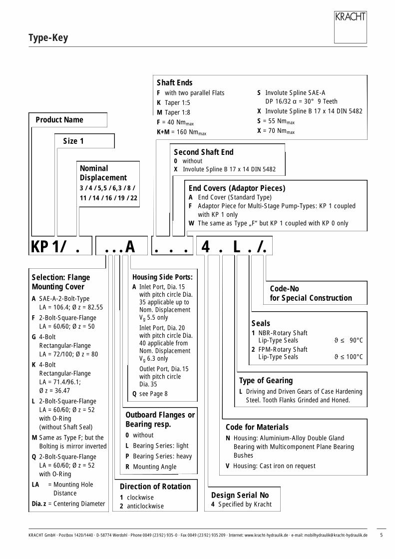
Type-Key
Product Name
NominalDisplacement3 / 4 / 5,5 / 6,3 / 8 / 11 / 14 / 16 / 19 / 22
Direction of Rotation1 clockwise2 anticlockwise
Housing Side Ports:A Inlet Port, Dia. 15
with pitch circle Dia.35 applicable up toNom. DisplacementVg 5.5 only
Inlet Port, Dia. 20with pitch circle Dia.40 applicable fromNom. DisplacementVg 6.3 only
Outlet Port, Dia. 15with pitch circle Dia. 35
Q see Page 8
Shaft EndsF with two parallel FlatsK Taper 1:5M Taper 1:8F = 40 Nmmax
K+M = 160 Nmmax
Seals1 NBR-Rotary Shaft
Lip-Type Seals ϑ ≤ 90°C2 FPM-Rotary Shaft
Lip-Type Seals ϑ ≤ 100°C
End Covers (Adaptor Pieces)A End Cover (Standard Type)F Adaptor Piece for Multi-Stage Pump-Types: KP 1 coupled
with KP 1 onlyW The same as Type „F“ but KP 1 coupled with KP 0 only
Code-No for Special Construction
Size 1
KP 1/ . 4 . L . /.. . .. ..A
Selection: FlangeMounting CoverA SAE-A-2-Bolt-Type
LA = 106.4; Ø z = 82.55
F 2-Bolt-Square-FlangeLA = 60/60; Ø z = 50
G 4-Bolt Rectangular-FlangeLA = 72/100; Ø z = 80
K 4-Bolt Rectangular-FlangeLA = 71.4/96.1; Ø z = 36.47
L 2-Bolt-Square-FlangeLA = 60/60; Ø z = 52with O-Ring (without Shaft Seal)
M Same as Type F; but theBolting is mirror inverted
Q 2-Bolt-Square-FlangeLA = 60/60; Ø z = 52 with O-Ring
LA = Mounting HoleDistance
Dia.z = Centering Diameter
Type of GearingL Driving and Driven Gears of Case Hardening
Steel. Tooth Flanks Grinded and Honed.
Outboard Flanges orBearing resp.0 without
L Bearing Series: light
P Bearing Series: heavy
R Mounting Angle
Design Serial No4 Specified by Kracht
Code for MaterialsN Housing: Aluminium-Alloy Double Gland
Bearing with Multicomponent Plane BearingBushes
V Housing: Cast iron on request
Second Shaft End0 withoutX Involute Spline B 17 x 14 DIN 5482
S Involute Spline SAE-ADP 16/32 α = 30° 9 Teeth
X Involute Spline B 17 x 14 DIN 5482S = 55 Nmmax
X = 70 Nmmax
KRACHT GmbH · Postbox 1420/1440 · D-58774 Werdohl · Phone 0049 (23 92) 935-0 · Fax 0049 (23 92) 935 209 · Internet: www.kracht-hydraulik.de · e-mail: [email protected] 5

M 6-13 deep
Ø 35
Ø 15
100
14
23.5
7.5
13Ø d
h11
Ø 16
.5
15.7
-0.1
0 -0
.06
Ø 80
Ø 40
M 6-13 deep
E
F
Ø 9
118
100
34.5
90
84
72
AM = 30 Nm
100
Ø 9
Ø 15
13Ø d
15.7
Ø 17 -0
.10
-0.0
6Ø
80
Ø 40
1.5
M 6-13 deep
38E
F 7.5
1317
M 1
2x
1.5
M 6-13 deep
Ø 35
118
100
34.5
90
84
72
High Pressure Gear Pumps KP 1
G-Flange, Tapered Shaft End
G-Flange, Involute Spline Shaft End
Shaft End: Taper 1:5Hex. Lock Nut M 12 x 1.5DIN EN 28675Curved Spring washer B12 DIN 137Woodruff Key 3 x 6.5 DIN 6888
Ordering Code: KP 1/4 G10A K0A 4NL1
Ordering Code: KP 1/4 G10A X0A 4NL1
The Direction of Rotation as represented is clockwise. In case of Anticlockwise Rotation theInlet and Outlet Ports are opposite
Nominal3 4 5.5 6.3 8 11 14 16 19 22
Displacement
d 15.0 15.0 15.0 20.0 20.0 20.0 20.0 20.0 20.0 20.0
E 87.5 89.2 91.7 93.1 95.9 100.9 105.9 109.3 114.3 120.1
F 39.5 40.4 41.6 42.3 43.7 46.2 48.7 50.4 52.9 55.8
Weight kg 2.1 2.2 2.2 2.3 2.3 2.5 2.6 2.8 2.9 3.1
Shaft End: Involute SplineB 17 x 14 DIN 5482but tooth thickness Sw = 3.206Addendum Modification = +0.6
Outlet Port
Inlet Port
Outlet Port
Inlet Port
KRACHT GmbH · Postbox 1420/1440 · D-58774 Werdohl · Phone 0049 (23 92) 935-0 · Fax 0049 (23 92) 935 209 · Internet: www.kracht-hydraulik.de · e-mail: [email protected]

M 6-13 deep
Ø 35
Ø 15
R 12 h
11Ø
16.5
14
23.5
-0.0
5Ø
82.5
5
6.35
11
15.7
Ø 40
Ø d
M 6-13 deep
E
F
R 47
.6
100
Ø 11
Ø 23
18.3
106.4
84
M 6-13 deep
Ø 35
Ø 15
-0.1
3Ø
15.4
6
16
31.7
-0.0
5Ø
82.5
5
6.35
11
15.7
Ø 40
Ø d
M 6-13 deep
E
F
R 12
R 47
.6
100
Ø 11
Ø 23
18.3
106.4
84
AM = 30 NmM 1
0
-2 +315
-0.0
50 -0
.025
Ø 50
40.5
7.2
E
F
15.7
Ø 17
Ø 40
Ø d
1.5
M 6-13 deep 1317
M 1
2x1.
5
M 6-13 deep
Ø 35
Ø 15
MA = 50+10 Nm
MA = 50+10 Nm60
60 100
14.3
84
SAE A-Flange, Tapered Shaft End
SAE A-Flange, SAE A-Shaft
SAE A-Flange, Involute Spline Shaft End
Shaft End: Taper 1:5Hex. Lock Nut M 12 x 1.5DIN EN 28675Curved Spring washer B12 DIN 137Woodruff Key 3 x 6.5 DIN 6888
The Direction of Rotation as represented is clockwise. In case of Anticlockwise Rotationthe Inlet and Outlet Ports are opposite
Shaft End: Involute SplineSAE-A 9 T; D/P 16/32; α = 30°
Shaft End: Involute SplineB 17 x 14 DIN 5482
Ordering Code: KP 1/4 A10A K0A 4NL1
Ordering Code: KP 1/4 A10A S0A 4NL1
Ordering Code: KP 1/4 A10A X0A 4NL1
Nominal3 4 5.5 6.3 8 11 14 16 19 22
Displacement
d 15.0 15.0 15.0 20.0 20.0 20.0 20.0 20.0 20.0 20.0
E 87.5 89.2 91.7 93.1 95.9 100.9 105.9 109.3 114.3 120.1
F 39.5 40.4 41.6 42.3 43.7 46.2 48.7 50.4 52.9 55.8
Weight kg 2.5 2.6 2.6 2.7 2.7 2.9 3.0 3.2 3.3 3.5
High Pressure Gear Pumps KP 1
Outlet Port
Inlet Port
Outlet Port
Inlet Port
Outlet Port
Inlet Port
KRACHT GmbH · Postbox 1420/1440 · D-58774 Werdohl · Phone 0049 (23 92) 935-0 · Fax 0049 (23 92) 935 209 · Internet: www.kracht-hydraulik.de · e-mail: [email protected] 7

88
Ø 8.5
113
96.1
71.4
84
100
h11
Ø 16
.5
22
14
-0.0
5Ø
36.4
7
15.7
Ø 13.5
± 0.15Ø 30.213
M 6-13 deep
4.8F
E
M 8-13 deep
± 0.15Ø 39.7
Ø 20
M 6-13 deep
± 0.15Ø 30.2
Ø 13.5
8
High Pressure Gear Pumps KP 1
KRACHT GmbH · Postbox 1420/1440 · D-58774 Werdohl · Phone 0049 (23 92) 935-0 · Fax 0049 (23 92) 935 209 · Internet: www.kracht-hydraulik.de · e-mail: [email protected]
M 6-13 deep
± 0.15Ø 30.2
Ø 13.510
0
-0.0
5Ø
36.4
7M 1
2x1.
5
1.5
Ø 17
15.7
Ø d
± 0.15Ø 30.213
M 6-13 deep
4.8
18.2
12.1
39.5
F
E
M 8-13 deep
± 0.15Ø 39.7
Ø d
88
Ø 8.5
113
96.1
71.4
84
K-Flange, Tapered Shaft End 1 : 8
K-Flange, Involute Spline Shaft End
The Direction of Rotation as represented is clockwise. In case of Anticlockwise Rotation theInlet and Outlet Ports are opposite
The Direction of Rotation as represented is clockwise. In case of Anticlockwise Rotation theInlet and Outlet Ports are opposite
Shaft End: Taper 1:5Hex. Lock Nut M 12 x 1.5DIN EN 28675Curved Spring washer B12 DIN 137Woodruff Key 3 x 6.5 DIN 6888
Shaft End: Involute SplineB 17 x 14 DIN 5482but tooth thickness Sw = 3.206Addendum Modification = +0.6
Ordering Code: KP 1/4 K10Q M0A 4NL1
Ordering Code: KP 1/4 K10Q X0A 4NL1
Nominal3 4 5.5 6.3 8 11 14 16 19 22
Displacement
d 13.5 13.5 13.5 13.5 13.5 20.0 20.0 20.0 20.0 20.0
E 89.0 90.7 93.2 94.6 97.4 102.4 107.4 110.8 115.8 121.6
F 41.0 41.85 43.1 43.8 45.2 47.7 50.2 51.9 54.4 57.3
Weight kg 2.1 2.2 2.2 2.3 2.3 2.5 2.6 2.8 2.9 3.1
Inlet PortNG 3-8
Inlet PortNG 11-22
Outlet Port
Inlet PortNG 3-8
Inlet PortNG 11-22
Outlet Port

High Pressure Gear Pumps KP 1
KRACHT GmbH · Postbox 1420/1440 · D-58774 Werdohl · Phone 0049 (23 92) 935-0 · Fax 0049 (23 92) 935 209 · Internet: www.kracht-hydraulik.de · e-mail: [email protected]
AM = 30 NmM 1
0 -2 +315
-0.0
50 -0
.025
Ø 50
40.5
7.2
E
F
15.7
Ø 17
Ø 40
Ø d1.
5
M 6-13 tief 1317
M 1
2x1.
5
M 6-13 tief
Ø 35
Ø 15
MA = 50+10 Nm
MA = 50+10 Nm60
60 100
14.3
84
F-Flange, Tapered Shaft End
F-Flange, Involute Spline Shaft End
The Direction of Rotation as represented is clockwise. In case of Anticlockwise Rotation theInlet and Outlet Ports are opposite
The Direction of Rotation as represented is clockwise. In case of Anticlockwise Rotation theInlet and Outlet Ports are opposite
Shaft End: Taper 1:5Hex. Lock Nut M 12 x 1.5DIN EN 28675Curved Spring washer B12 DIN 137Woodruff Key 3 x 6.5 DIN 6888
Shaft End: Involute SplineB 17 x 14 DIN 5482but tooth thickness Sw = 3.206Addendum Modification = +0.6
Ordering Code: KP 1/4 F10A K0A 4NL1
Ordering Code: KP 1/4 F10A X0A 4NL1
Nominal3 4 5.5 6.3 8 11 14 16 19 22
Displacement
d 15.0 15.0 15.0 20.0 20.0 20.0 20.0 20.0 20.0 20.0
E 85.0 86.7 89.2 90.6 93.4 98.4 103.4 106.8 111.8 117.6
F 37.0 37.9 39.1 39.8 41.2 43.7 46.2 47.9 50.4 53.3
Weight kg 2.1 2.2 2.2 2.3 2.3 2.5 2.6 2.8 2.9 3.1
Inlet Port
Outlet Port
M 6-13 deep
Ø 35
Ø 15
MA = 50+10 Nm
MA = 50+10 Nm14
h11
Ø 16
.5
26
M 1
0
-2 +315
-0.0
50 -0
.025
Ø 50
7.2
E
F
15.7
Ø 40
Ø d
M 6-13 deep60
60 100
14.3
84
Inlet Port
Outlet Port
9

High Pressure Gear Pumps KP 1
KRACHT GmbH · Postbox 1420/1440 · D-58774 Werdohl · Phone 0049 (23 92) 935-0 · Fax 0049 (23 92) 935 209 · Internet: www.kracht-hydraulik.de · e-mail: [email protected]
AM = 30 NmM 1
0 -2 +315
-0.0
50 -0
.025
Ø 50
40.5
7.2
E
F
15.7
Ø 17
Ø 40
Ø d
1.5
M 6-13 deep 1317
M 1
2x1.
5
M 6-13 deep
Ø 35
Ø 15
MA = 50+10 Nm
MA = 50+10 Nm
60
60 100
14.3
84
M-Flange, Tapered Shaft End
M-Flange, Involute Spline Shaft End
The Direction of Rotation as represented is clockwise. In case of Anticlockwise Rotation theInlet and Outlet Ports are opposite
The Direction of Rotation as represented is clockwise. In case of Anticlockwise Rotation theInlet and Outlet Ports are opposite
Shaft End: Taper 1:5Hex. Lock Nut M 12 x 1.5DIN EN 28675Curved Spring washer B12 DIN 137Woodruff Key 3 x 6.5 DIN 6888
Shaft End: Involute SplineB 17 x 14 DIN 5482but tooth thickness Sw = 3.206Addendum Modification = +0.6
Ordering Code: KP 1/4 M10A K0A 4NL1
Ordering Code: KP 1/4 M10A X0A 4NL1
Nominal3 4 5.5 6.3 8 11 14 16 19 22
Displacement
d 15.0 15.0 15.0 20.0 20.0 20.0 20.0 20.0 20.0 20.0
E 85.0 86.7 89.2 90.6 93.4 98.4 103.4 106.8 111.8 117.6
F 37.0 37.9 39.1 39.8 41.2 43.7 46.2 47.9 50.4 53.3
Weight kg 2.1 2.2 2.2 2.3 2.3 2.5 2.6 2.8 2.9 3.1
Inlet Port
Outlet Port
M 6-13 deep
Ø 35
Ø 15
MA = 50+10 Nm
MA = 50+10 Nm
h11
Ø 16
.5
14
26
M 1
0
-2 +315
-0.0
50 -0
.025
Ø 50
7.2
E
F
15.7
Ø 40
Ø d
M 6-13 deep60
60 100
14.3
84
Inlet Port
Outlet Port
MA = 50+10 Nm
MA = 50+10 Nm
M 6-13 deep
Ø 35
Ø 15
-0.0
6 -0
.03
Ø 52
7.2
h11
Ø 16
.5
14
26
M 1
0
-2 +315
E
F
15.7
Ø 40
Ø d
M 6-13 deep60
60 100
14.3
84
AM = 30 Nm
-0.0
6 -0
.03
Ø 52
M 1
0 -2 +315
40.5
7.2
E
F
15.7
Ø 17
Ø 40
Ø d
1.5
M 6-13 deep 1317
M 1
2x1.
5
M 6-13 deep
Ø 35
Ø 15
MA = 50+10 Nm
MA = 50+10 Nm 60
60 100
14.3
84
High Pressure Gear Pumps KP 1
KRACHT GmbH · Postbox 1420/1440 · D-58774 Werdohl · Phone 0049 (23 92) 935-0 · Fax 0049 (23 92) 935 209 · Internet: www.kracht-hydraulik.de · e-mail: [email protected] 11
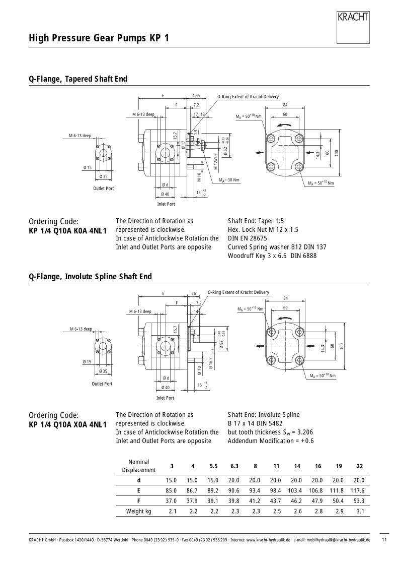
Q-Flange, Tapered Shaft End
Q-Flange, Involute Spline Shaft End
The Direction of Rotation as represented is clockwise. In case of Anticlockwise Rotation theInlet and Outlet Ports are opposite
The Direction of Rotation as represented is clockwise. In case of Anticlockwise Rotation theInlet and Outlet Ports are opposite
Shaft End: Taper 1:5Hex. Lock Nut M 12 x 1.5DIN EN 28675Curved Spring washer B12 DIN 137Woodruff Key 3 x 6.5 DIN 6888
Shaft End: Involute SplineB 17 x 14 DIN 5482but tooth thickness Sw = 3.206Addendum Modification = +0.6
Ordering Code: KP 1/4 Q10A K0A 4NL1
Ordering Code:KP 1/4 Q10A X0A 4NL1
Nominal3 4 5.5 6.3 8 11 14 16 19 22
Displacement
d 15.0 15.0 15.0 20.0 20.0 20.0 20.0 20.0 20.0 20.0
E 85.0 86.7 89.2 90.6 93.4 98.4 103.4 106.8 111.8 117.6
F 37.0 37.9 39.1 39.8 41.2 43.7 46.2 47.9 50.4 53.3
Weight kg 2.1 2.2 2.2 2.3 2.3 2.5 2.6 2.8 2.9 3.1
Inlet Port
Outlet Port
Inlet Port
Outlet Port
O-Ring Extent of Kracht Delivery
O-Ring Extent of Kracht Delivery

M 6-13 deep
Ø 35
Ø 15
MA = 50+10 Nm
MA = 50+10 Nm
-0.0
6 -0
.03
Ø 52
7.2
M 1
0
-2 +315
E
F
15.7
Ø 40
Ø d
M 6-13 deep 60
60 100
14.3
84
2
Ø 17
6.5
2.7
Ø 40
Ø 32
-0.0
83 -0
.025
8
M 6-13 deep
Ø 35
Ø 15
MA = 50+10 Nm
MA = 50+10 Nm2
-0.0
6 -0
.03
Ø 52
7.2
M 1
0
-2 +315
E
F
15.7
Ø 40
Ø d
M 6-13 deep 60
60 100
14.3
8414
2.8
h11
16.5
Ø 18
Ø 40
Ø 32
High Pressure Gear Pumps KP 1
KRACHT GmbH · Postbox 1420/1440 · D-58774 Werdohl · Phone 0049 (23 92) 935-0 · Fax 0049 (23 92) 935 209 · Internet: www.kracht-hydraulik.de · e-mail: [email protected]
L-Flange, Parallel Flat Shaft End
L-Flange, Involute Spline Shaft End
The Direction of Rotation as represented is clockwise. In case of Anticlockwise Rotation theInlet and Outlet Ports are opposite
The Direction of Rotation as represented is clockwise. In case of Anticlockwise Rotation theInlet and Outlet Ports are opposite
Shaft End: Involute SplineB 17 x 14 DIN 5482but tooth thickness Sw = 3.206Addendum Modification = +0.6
Ordering Code: KP 1/4 L10A F0A 4NL1
Ordering Code: KP 1/4 L10A X0A 4NL1/204
Nominal3 4 5.5 6.3 8 11 14 16 19 22
Displacement
d 15.0 15.0 15.0 20.0 20.0 20.0 20.0 20.0 20.0 20.0
E 85.0 86.7 89.2 90.6 93.4 98.4 103.4 106.8 111.8 117.6
F 37.0 37.9 39.1 39.8 41.2 43.7 46.2 47.9 50.4 53.3
Weight kg 2.1 2.2 2.2 2.3 2.3 2.5 2.6 2.8 2.9 3.1
Inlet Port
O-Ring Extent of Kracht Delivery
Outlet Port
Inlet Port
Outlet Port
O-Ring Extent of Kracht Delivery

2,5
2,0
1,5
1,0
0,5
00 10 20 30 40 50
l in mm
FR in
kN
60 70
2,5
2,0
1,5
1,0
0,5
00 10 20 30 40 50
l in mm
FR in
kN
AM = 63 Nm
RF
l
8
14
2
Ø 20
15.520M
14x
1.5
-0.1
0 -0
.06
Ø 80
4734
Ø 9
R 9
M 10-22 deep
15.7
60
72
100
34.5
60
RF
l
38
63.5
AM = 63 Nm
Ø 9
Ø 20
2
920
53.5
1520
M 1
4x1.
5
-0.1
0 -0
.06
Ø 80
37.5
R 10
72
100
34.5
60
M 10-22 deep
15.7
60
Outboard Bearing Type P, Tapered Shaft End
Weight of the Outboard Bearing = 1.0 kg
Outboard Bearing L, Tapered Shaft End KP1/4L1LA F0A 4NL1 Parallel Flat Shaft End 40 Nmmax
alternativ KP1/4 L1LA X0A 4NL1 Involute Spline Shaft End 70 Nmmax
Dimensions and type see Page 12
Shaft End: Taper 1:5Hex. Lock Nut M 14 x 1.5DIN EN 28675Curved Spring washer B14 DIN 127Woodruff Key 4 x 6.5 DIN 6888
Permissible Radial Load FR
as Function of the SupportingDistance l (for Lh = 10.000 h)FR = f(l)
Permissible Radial Load FR
as Function of the SupportingDistance l (for Lh = 10.000 h)FR = f(l)
Shaft End: Taper 1:5Hex. Lock Nut M 14 x 1.5DIN EN 28675Curved Spring washer B14 DIN 127Woodruff Key 4 x 6.5 DIN 6888
Ordering Code: KP 1/4 L1LA F0A 4NL1
Ordering Code: KP 1/4 Q1PA X0A 4NL1
High Pressure Gear Pumps KP 1
KRACHT GmbH · Postbox 1420/1440 · D-58774 Werdohl · Phone 0049 (23 92) 935-0 · Fax 0049 (23 92) 935 209 · Internet: www.kracht-hydraulik.de · e-mail: [email protected] 13
Outboard Bearing Type L, Tapered Shaft End
Weight of the Outboard Bearing = 3.5 kg
21,5 Middle of the Shaft End
n = 1000 min-1
n = 2000 min-1
n = 3000 min-1
n = 4000 min-1
n = 1000 min-1
n = 2000 min-1
n = 3000 min-1
n = 4000 min-1
38 Middle of the shaft End
Middle of the Bearing

AM = 30 Nm
1.5
Ø 17
19.5
48
28
13Ø
50
40.5
7.5
E
F
15.7
Ø 40
Ø d
M 6-13 deep 1317M
12x
1.5
M 6-13 deep
Ø 35
Ø 15
Ø 11
120
50
85
5590
60
100
84
Shaft End: Taper 1:5Hex. Lock Nut M 12 x 1.5DIN EN 28675Curved Spring washer B12 DIN 137Woodruff Key 3 x 6.5 DIN 6888
Ordering Code: KP 1/4 F1RA K0A 4NL1
High Pressure Gear Pumps KP 1
KRACHT GmbH · Postbox 1420/1440 · D-58774 Werdohl · Phone 0049 (23 92) 935-0 · Fax 0049 (23 92) 935 209 · Internet: www.kracht-hydraulik.de · e-mail: [email protected]
Mounting Angle, Tapered Shaft End
Pressure Relief Valve
Nominal 3 4 5.5 6.3 8 11 14 16 19 22
Displacement
d 15.0 15.0 15.0 20.0 20.0 20.0 20.0 20.0 20.0 20.0
E 85.0 86.7 89.2 90.6 93.4 98.4 103.4 106.8 111.8 117.6
F 37.0 37.9 39.1 39.8 41.2 43.7 46.2 47.9 50.4 53.3
Weight kg 3.7 3.8 3.8 3.9 3.9 4.1 4.2 4.4 4.5 4.7
Ordering Set Set Discharge Discharge-Code Pressure Pressure Flow Flow
Pv1 Pv2 Q1 max Q2 max
bar bar l/min l/min
DBD 10 D 1 A 300 10 280 15 75
DBD 10 D 1 A 200 10 200 15 70
DBD 10 D 1 A 150 10 150 10 55
DBD 10 D 1 A 850 10 85 10 45
DBD 10 D 1 A 400 10 40 10 30
DBD 10 D 1 A 160 5 16 9 20
Inlet Port
Outlet Port
60
169.
5
92.5
66
a Straight Flanged Connection GDA 1/12 1/16
b Elbow Flanged Connection WDA 1/12 1/16
Tank Connection G 1⁄2* Fixing Screws
a Straight Flanged Connection 4 Pieces M6 x 70 DIN 912
b Elbow Flanged Connection 2 Pieces M6 x 70 DIN 9122 Pieces M6 x 85 DIN 912
* Disc acc. to Drawing No 17 406/5
* O-Ring 18 x 2,5 (2 Pieces)
Pressure Gauge Port G 1⁄4
*Extent of KRACHT Delivery

High Pressure Gear Pumps KP 1
KRACHT GmbH · Postbox 1420/1440 · D-58774 Werdohl · Phone 0049 (23 92) 935-0 · Fax 0049 (23 92) 935 209 · Internet: www.kracht-hydraulik.de · e-mail: [email protected] 15
Tandem Pump, Tapered Shaft End
The Direction of Rotation as represented is clockwise. In case of Anticlockwise Rotation theInlet and Outlet Ports are opposite
Ordering Code: KP 1/4 G10A KXA 4NL1/271 +KP 1/4 010U X0A 4NL1/271
multistage with other flanges and shaft possible
Ordering Code: KP 1/4 G10A KXF 4NL1/271 +KP 1/4 010A X0A 4NL1/271
Shaft End: Taper 1:5Hex. Lock Nut M 12 x 1.5DIN EN 28675Curved Spring washer B12 DIN 137Woodruff Key 3 x 6.5 DIN 6888
AM = 30 Nm
M 6
-13
deep
Ø 35
Ø 15
M 6
-13
deep
Ø 35
Ø 15
100 Ø
17
15.7
Q M
M 6-13 deep
Ø 40
Ø 20
1.5
-0.1
0 -0
.06
Ø 80
M 1
2x1.
5
13
13
16
7.5M
38L
84
34.5
118
100
Ø 9
72
90
AM = 30 Nm
100
Q
M 6-13 deep
Ø 20
Ø 40Ø 40
Ø 20
M 6-13 deep
Ø 17
15.7 1.5
-0.1
0 -0
.06
Ø 80
M 1
2x1.
5
13
13
16
7.5M
38L
maximal Capacity at npsh = 1 m
Viscosity ν = 120 mm2/s 34 mm2/s
Qmax at pipe size 28 L 65 l/min 90 l/minQmax at pipe size 35 L 85 l/min 110 l/min
Maximum shaft:(p1 *V1 + p2 *V2) ≤ 9000
p1.2 = pressure in barV1.2 = Displacement in cm3
Common Inlet Ports
Outlet Ports
Inlet Ports
M Nominal 1. StageDisplacement 22 19 16 14 11 8 6.3 5.5 4 3
Q L Q L Q L Q L Q L Q L Q L Q L Q L Q L
3 39.5 3 103.8 207.6 100.9 201.8 98.4 196.8 96.7 193.4 94.2 188.4 91.7 183.4 90.3 180.6 89.6 179.2 88.4 176.7 87.5 175.0
4 40.4 4 104.7 209.3 101.7 203.5 99.2 198.5 97.6 195.1 95.0 190.1 92.6 185.1 91.2 182.3 90.5 180.9 89.2 178.5
5.5 41.6 5.5 105.9 212.1 103.0 206.0 100.5 201.0 98.8 197.6 96.3 192.6 93.8 187.6 92.4 184.8 91.7 183.4
6.3 42.3 6.3 106.6 213.2 103.7 207.4 101.2 202.4 99.5 199.0 97.0 194.0 94.5 189.0 93.1 186.1
8 43.7 8 108.0 216.0 105.1 210.2 102.6 205.2 100.9 201.8 98.4 196.8 95.9 191.8
11 46.2 11 110.5 221.0 107.6 215.2 105.1 210.2 103.4 206.8 100.9 201.8
14 48.7 14 113.0 226.0 101.1 220.2 107.6 215.2 105.9 211.8
16 50.4 16 114.7 229.4 111.8 223.6 109.3 218.6
19 52.9 19 117.2 234.4 114.3 228.6
22 55.8 22 120.1 240.2
2. S
tage
Nom
inal
Disp
lace
men
t

High Pressure Gear Pumps KP 1
KRACHT GmbH · Postbox 1420/1440 · D-58774 Werdohl · Phone 0049 (23 92) 935-0 · Fax 0049 (23 92) 935 209 · Internet: www.kracht-hydraulik.de · e-mail: [email protected]
Coupling Weight Moment Rough Bore Finished Bore Dimensions OrderingSize of
min. min. max. max.Code
InertiaPart Part Part Part Part Part
kg kgm2 2 3 2 3 2 3 l l1 E s b L M M1 DH D D1 dH
24 0.20 0.00008 – – 9 – 24 – 30 18.5 18 2 14 66.5 24 12.5 55 40 – 27 RA 24-K18/17-Z 30/...
28 0.35 0.0002 – – 10 – 28 – 35 18.5 20 2.5 15 73.5 28 11.5 65 48 – 30 RA 28-K18/17-Z 35/...Type38 0.75 0.0007 – – 12 – 38 – 45 18.5 24 3 18 87.5 37 10.5 80 66 – 38 RA 38-K18/17-Z 45/...A
42 1.15 0.0014 25 – 28 – 42 – 50 18.5 26 3 20 94.5 40 8.5 95 75 – 46 RA 42-K18/17-Z 50/...
24/28 0.22 0.0001 – 20 – 22 – 28 30 18.5 18 2 14 66.5 24 12.5 55 40 56 27 RA 24/38-K18/17-Z 30/...
Type28/38 0.42 0.0003 – 23 – 28 – 38 35 18.5 20 2.5 15 73.5 28 11.5 65 48 67 30 RA 28/38-K18/17-Z 35/...
B 38/45 0.82 0.0008 – 36 – 38 – 45 45 18.5 24 3 18 87.5 37 10.5 80 66 77 38 RA 38/45-K18/17-Z 45/...
38/45 2.50 0.0020 – – – 38 – 45 70 18.5 24 3 18 112.5 62 10.5 80 66 78 38 RA 38/45-K18/17-Z 70/...
42/55 1.29 0.0018 – 25 – 42 – 55 50 18.5 26 3 20 94.5 40 8.5 95 75 94 46 RA 42/55-K18/17-Z 50/...
Operating Temperatur: – 40 °C bis + 90 °C (Short Time Temperature peaks up to + 120 °C are permissible) RA: Hub Material AlWeights as well as Moments of Inertia relate to the max. bore dia. after final machining – but without key-way. RG: Hub Material Part 2 and 3 GGBore Finish acc. to ISO-Fit Class H7; Key-Ways acc. to DIN 6885 / Part 1.
Couplings and Accessories
b
dH
ss
E ll1
MM1
DDH D
L
b
dH
lEl1
M1
s
M
s
D
L
DH D
Internal Flexible Coupling Block ofPolyurethane (Vulkollan)Shore Hardness 92°Colour: Natural coloured
Taper 1:5
Type A Type B
Part 1 Part 2 Part 1 Part 3
RA 38 – K 18/17 – Z 45/38
Coupling SizeLength of the CouplingHub and the Hub BorePump Sided
Length of the Coupling Huband the Hub Bore Motor SidedStraight Hub Bore
Ordering Code:
Taper 1:5
Ø 25
32
Ø 39
.6
19
9
15.8
Ø 19
H8
8
Ø 30 12
Coupling Sleeve: Coupling:
Retaining Ring14 x 1 DIN 472
Internal InvoluteA 17 x 14DIN 5482 Blatt 1
Coupling Sleeve Size 1 Partnumber : B.0079020001
Coupling KP1 K-ShaftPartnumber : E.0187220001
Coupling KP 1L Partnumber: E.0104040001

KRACHT GmbH · Postbox 1420/1440 · D-58774 Werdohl · Phone 0049 (23 92) 935-0 · Fax 0049 (23 92) 935 209 · Internet: www.kracht-hydraulik.de · e-mail: [email protected] 17
High Pressure Gear Pumps KP 1
Straight Flanged Connector
Elbow Flanged Connector
1 LL
32
1
L
LL
L1 Hex. Socket Head Cap Screw (DIN 912 – 8.8)2 Single Coil Spring Lock Washer (A6 DIN 127)3 Covering Nut with Cutting Ring (SW)
Ordering Code of a complete connection:For the Inlet Port:Straight Flanged Connector GSA 1/22For the Outlet Port:Elbow Flanged Connector WDA 1/20
Extend of Kracht Delivery: Hex. Socket HeadCap Screw acc. to DIN 912 as well as SingleCoil Spring Lock Washers and O-Rings.
Inlet Port Ordering Discharge Flow Dimensions Cap Screws WeightPipe Externa Dia. Code Q in l/min
mm at 34 mm2/s L SW kg
22 GSA 1/22 45 86 36 4 x M6 x 22 0.23
18 GSA 1/18 30 86 32 4 x M6 x 22 0.22
15 GSA 1/15 12 85 27 4 x M6 x 22 0.19
Outlet Port Ordering Rated Pressure Dimensions Cap Screws WeightPipe Externa Dia. Code PN in bar
mm L1 SW kg
16 GDA 1/16 315 82 30 4 x M6 x 22 0.18
15 GDA 1/15 250 81 27 4 x M6 x 22 0.17
12 GDA 1/12 315 81 22 4 x M6 x 22 0.16
Inlet Port Ordering Discharge Flow Dimensions Cap Screws WeightPipe Externa Dia. Code Q in l/min
mm at 34 mm2/s L L3 SW kg
35 WSA 1/35 65 52 74 50 2 x M6 x 60 2 x M6 x 22 0.55
28 WSA 1/28 45 49 70 41 2 x M6 x 50 2 x M6 x 20 0.38
22 WSA 1/22 25 47 64.5 36 4 x M6 x 22 0.27
18 WSA 1/18 18 47 64.5 32 4 x M6 x 22 0.25
15 WSA 1/15 12 46 64.5 27 4 x M6 x 22 0.23
Outlet Port Ordering Rated Pressure Dimensions Cap Screws WeightPipe Externa Dia. Code PN in bar
mm L1 L2 SW kg
20 WDA 1/20 315 56 67 36 2 x M6 x 45 2 x M6 x 22 0.40
16 WDA 1/16 315 48 62 30 2 x M6 x 40 2 x M6 x 22 0.28
15 WDA 1/15 250 46 58.5 27 2 x M6 x 35 2 x M6 x 22 0.22
12 WDA 1/12 315 47 58.5 22 2 x M6 x 35 2 x M6 x 22 0.20
1 23
123
GDA GSAO-Ring
(20 x 2.5)
O-Ring (20 x 2.5) O-Ring (26 x 2.5)
O-Ring(24 x 2.5)
1 2
3WDA WSA
3
12
KRACHT GmbH · Postbox 1420/1440 · D-58774 Werdohl · Phone 0049 (23 92) 935-0 · Fax 0049 (23 92) 935 209 · Internet: www.kracht-hydraulik.de · e-mail: [email protected]
High Pressure Gear Pumps KP 1
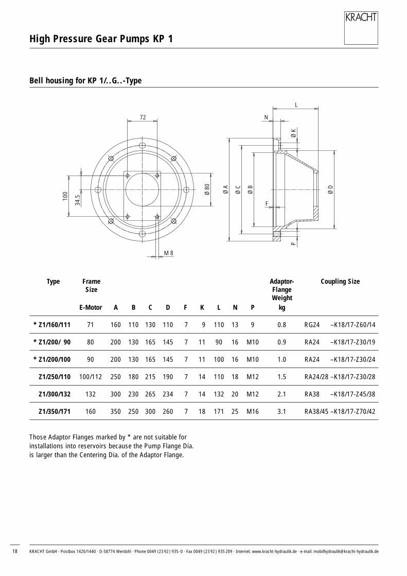
Bell housing for KP 1/..G..-Type
Those Adaptor Flanges marked by * are not suitable forinstallations into reservoirs because the Pump Flange Dia.is larger than the Centering Dia. of the Adaptor Flange.
Ø 80
M 8
100
34.5
72
F
Ø D
PØ
K
Ø B
Ø C
Ø A
N
L
Type Frame Adaptor- Coupling SizeSize Flange
WeightE-Motor A B C D F K L N P kg
* Z1/160/111 71 160 110 130 110 7 9 110 13 9 0.8 RG24 –K18/17-Z60/14
* Z1/200/ 90 80 200 130 165 145 7 11 90 16 M10 0.9 RA24 –K18/17-Z30/19
* Z1/200/100 90 200 130 165 145 7 11 100 16 M10 1.0 RA24 –K18/17-Z30/24
Z1/250/110 100/112 250 180 215 190 7 14 110 18 M12 1.5 RA24/28 –K18/17-Z30/28
Z1/300/132 132 300 230 265 234 7 14 132 20 M12 2.1 RA38 –K18/17-Z45/38
Z1/350/171 160 350 250 300 260 7 18 171 25 M16 3.1 RA38/45 –K18/17-Z70/42

KRACHT GmbH · Postbox 1420/1440 · D-58774 Werdohl · Phone 0049 (23 92) 935-0 · Fax 0049 (23 92) 935 209 · Internet: www.kracht-hydraulik.de · e-mail: [email protected] 19
High Pressure Gear Pumps KP 1
Motor with pump
f
c
g
p
h
b
e
a1
L1
w1 a
s
L
Frame Size Dimensions in mmL a1 a b c e g h L1 p s w1
80S 90 200 100 125 5 120 156 80 244 199 10 5080 90 200 100 125 5 120 156 80 244 199 10 50
90S 100 200 100 140 12 158 190 90 258 210 9 5690L 100 200 125 140 12 158 190 90 258 210 10 56
100LS 110 250 140 160 12 172 213 100 298 232 12 63100L 110 250 140 160 12 172 213 100 298 232 12 63112M 110 250 140 190 12 172 234 112 325 252 12 70
132S 132 300 140 216 12 187 265 132 358 283 12 89132M 132 300 178 216 12 218 298 132 399 303 12 89
160M 171 350 210 254 16 306 323 160 476 341 15 108160L 171 350 254 254 16 306 323 160 476 341 15 108
Frame Power Operating Power Operating Bell- Coupling Weight E-Motor Bell-Size Speed Speed housing housing
Motor 6-pole Motor 4-pole kgkW rpm kW rpm 6-pole 4-pole kg
80S 0.37 920 0.55 1400 Z1/200/90-K RA 24-K18/17-Z30/19 11 10 0.980 0.55 910 0.75 1400 12 11
90S 0.75 925 1.1 1410 Z1/200/100-K RA 24-K18/17-Z30/24 13 13 1.090L 1.10 935 1.5 1420 17 15
100LS — — 2.2 1420 — 21100L 1.50 940 3.0 1430 Z1/250/110-K RA 24/28-K18/17-Z30/28 20 24 1.5112M 2.20 945 4.0 1440 29 31
132S 3.00 955 5.5 1445 Z1/300/132-K RA 28/38-K18/17-Z35/38 36 39 2.1132M 4.00 960 7.5 1450 63 60
160M 7.50 960 11.0 1450 Z1/350/171-K RA 38/45-K18/17-Z70/42 76 76 3.1160L 11 . 00 960 15.0 1450 94 90
Motor frame sizes are based on Schäfer. Other manufactures motors canbe supplied on request as IM B 35.

KP1.e.12.2000
KRACHT GmbH · Postbox 1420/1440 · D-58774 Werdohl · Phone 0049 (23 92) 935-0 · Fax 0049 (23 92) 935 209 · Internet: www.kracht-hydraulik.de · e-mail: [email protected]
Transfer pumps
Transfer pumps for lubrica-ting oil supply equipment,low pressure filling and feedsystems, dosing and mixingsystems, including PUR.
Industrial hydraulics
Cetop directional controland proportional valves,hydraulic cylinders, pressure,quantity and stop valves forpipe and slab construction,hydraulic accessories forindustrial hydraulics (mobile and stationary use).
Volutronic®
Gear flow meters and electronics for volume andflow metering technology in hydraulics, processingand laquering technology.
Mobile hydraulics
Single and multistage high pressure gear pumps, hydraulic motors and valvesfor construction machinery, vehicle-mounted machines.
With our decades of experience, we are at yourside, world-wide, for the professional mastery of specific applications andcomplete solutions inhydraulics and process technology.
Overview ofour completeprogramme