high pressure double diaphragm pump - wsb finishing...
TRANSCRIPT
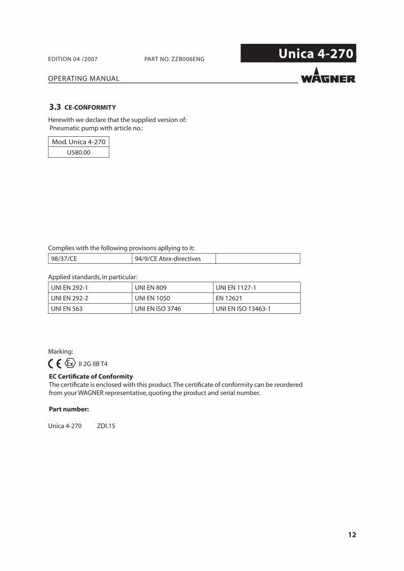
II 2G IIB T4
High pressureDouble diaphragm pump
Unica 4-270
Edition 04 / 2007
Translation of the original
Operating Manual

3
Unica 4-270.
OPERATING MANUAL
EDITION 04 /2007 PART NO. ZZB006ENG
Contents
1 ABOUT THESE INSTRUCTIONS 51.1 Languages 51.2 Warnings, notes and symbols in these instructions 5
2 GENERAL SAFETY INSTRUCTIONS 62.1 Safety instructions for the operator 62.1.1 Electrical equipment 62.1.2 Personnel qualifi cations 62.1.3 A safe work environment 62.2 Safety instructions for staff 62.2.1 Safe handling of WAGNER spray units 72.2.2 Earth the unit 72.2.3 Material hoses 72.2.4 Cleaning 82.2.5 Handling hazardous liquids, varnishes and paints 82.2.6 Touching hot surfaces 82.3 Correct use 82.4 Use in an explosion hazard area 92.4.1 Correct use 92.4.2 Explosion protection identifi cation 92.4.3 Max. surface temperature 92.4.4 Safety regulations 9
3 PRODUCT LIABILITY AND WARRANTY 113.1 Important notes on product liability 113.2 Warranty 113.3 CE-CONFORMITY 12
4 DESCRIPTION 134.1 Field of application 134.1.1 Using in accordance with the instructions 134.1.2 Examples of application areas 134.2 Extent of delivery 144.3 Data 144.3.1 Materials used for components in contact with the product 144.3.2 Technical data 154.3.3 Dimensions and connections 174.3.4 Performance diagrams 184.4 Functioning 194.4.1 Pump 194.4.2 Air supply unit (optional) 20
5 STARTING UP AND OPERATING 215.1 Installation and connection 215.1.1 Pump wall-installation 215.1.2 Pump installation on ground frame 215.1.3 Compressed air supply circuit 225.1.4 Suction circuit 225.1.5 Delivery circuit 22
4
Unica 4-270.
OPERATING MANUAL
EDITION 04 /2007 PART NO. ZZB006ENG
Contents5.1.6 Example of typical installation 235.1.7 Earthing 245.2 Start up 265.2.1 Safety regulations 265.2.2 Pressure release procedure 285.2.3 Pump washing 285.2.4 Filling with working fl uid 285.2.5 Pump stop 285.3 Finishing work and cleaning 295.4 Storing for longer periods of time 29
6 FAULT LOCATION, MAINTENANCE AND REPAIR 306.1 Trouble shooting and solution 306.2 Maintenance 326.2.1 Lubrication 326.2.2 Washing and storing 326.2.3 Regular check of sealing and tightness 326.2.4 Plan of preventive maintenance 326.3 Pump repair 336.3.1 Maintenance of the hydraulic circuit 336.3.1.1 Operations on the hydraulic circuit during maintenance 356.3.1.2 Hydraulic circuit emptying 356.3.1.3 Hydraulic circuit fi lling 35
7 ACCESSORIES 367.1 Wall mounting kit 367.2 Stand kit 377.3 Air pressure regulator kit 38
8 SPARE PARTS 398.1 How to order spare parts 398.2 Overview modules 418.3 Air motor 428.3.1 Pneumatic feeler 448.3.2 Reversing valve 458.4 Hydraulic circuit 468.5 Fluid section 48
5
Unica 4-270.
OPERATING MANUAL
EDITION 04 /2007 PART NO. ZZB006ENG
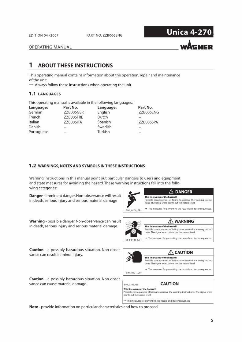
1.2 WARNINGS, NOTES AND SYMBOLS IN THESE INSTRUCTIONS
1 ABOUT THESE INSTRUCTIONS
1.1 LANGUAGES
ZZB006GER ZZB006ENG ZZB006FRE -- ZZB006ITA ZZB006SPA -- -- -- --
6
Unica 4-270.
OPERATING MANUAL
EDITION 04 /2007 PART NO. ZZB006ENG
2 GENERAL SAFETY INSTRUCTIONS
2.1 SAFETY INSTRUCTIONS FOR THE OPERATOR
2.1.1 ELECTRICAL EQUIPMENT
2.1.2 PERSONNEL QUALIFICATIONS
2.1.3 A SAFE WORK ENVIRONMENT
2.2 SAFETY INSTRUCTIONS FOR STAFF
7
Unica 4-270.
OPERATING MANUAL
EDITION 04 /2007 PART NO. ZZB006ENG
2.2.1 SAFE HANDLING OF WAGNER SPRAY UNITS
2.2.2 EARTH THE UNIT
2.2.3 MATERIAL HOSES
8
Unica 4-270.
OPERATING MANUAL
EDITION 04 /2007 PART NO. ZZB006ENG
2.2.4 CLEANING
2.2.5 HANDLING HAZARDOUS LIQUIDS, VARNISHES AND PAINTS
2.2.6 TOUCHING HOT SURFACES
2.3 CORRECT USE
9
Unica 4-270.
OPERATING MANUAL
EDITION 04 /2007 PART NO. ZZB006ENG
2.4.1 CORRECT USE
2.4.2 EXPLOSION PROTECTION IDENTIFICATION
2.4.3 MAX. SURFACE TEMPERATURE
2.4.4 SAFETY REGULATIONS
2.4 USE IN AN EXPLOSION HAZARD AREA
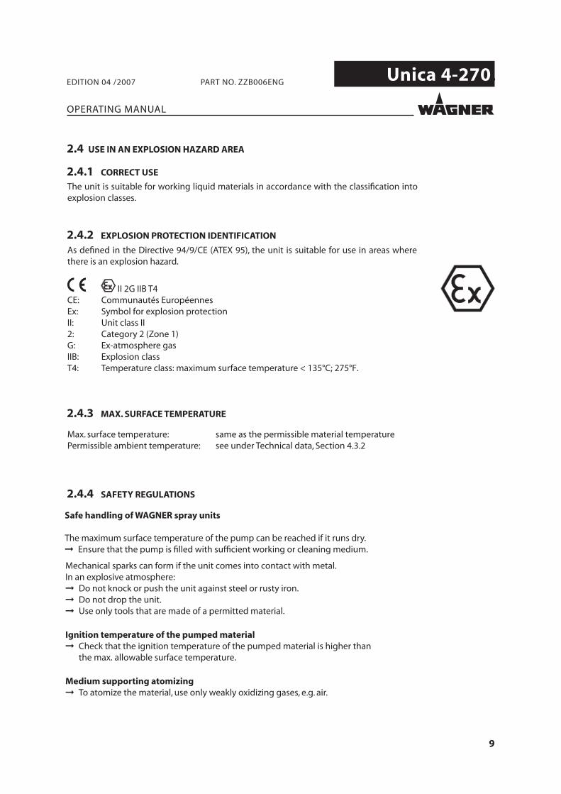
As defined in the Directive 94/9/CE (ATEX 95), the unit is suitable for use in areas wherethere is an explosion hazard.
II 2G IIB T4CE: Communautés EuropéennesEx: Symbol for explosion protectionII: Unit class II 2: Category 2 (Zone 1) G: Ex-atmosphere gas IIB: Explosion class T4: Temperature class: maximum surface temperature < 135°C; 275°F.
Max. surface temperature: same as the permissible material temperaturePermissible ambient temperature: see under Technical data, Section 4.3.2
Safe handling of WAGNER spray units
The maximum surface temperature of the pump can be reached if it runs dry.Ensure that the pump is filled with sufficient working or cleaning medium.
Mechanical sparks can form if the unit comes into contact with metal.In an explosive atmosphere:
Do not knock or push the unit against steel or rusty iron.Do not drop the unit.Use only tools that are made of a permitted material.
Ignition temperature of the pumped materialCheck that the ignition temperature of the pumped material is higher than the max. allowable surface temperature.
Medium supporting atomizingTo atomize the material, use only weakly oxidizing gases, e.g. air.
10
Unica 4-270.
OPERATING MANUAL
EDITION 04 /2007 PART NO. ZZB006ENG
11
Unica 4-270.
OPERATING MANUAL
EDITION 04 /2007 PART NO. ZZB006ENG
3 PRODUCT LIABILITY AND WARRANTY
3.1 IMPORTANT NOTES ON PRODUCT LIABILITY
3.2 WARRANTY
12
Unica 4-270.
II 2G IIB T4
OPERATING MANUAL
EDITION 04 /2007 PART NO. ZZB006ENG
3.3 CE-CONFORMITY
Complies with the following provisons apllying to it:
98/37/CE 94/9/CE Atex-directives
Applied standards, in particular:
UNI EN 292-1 UNI EN 809 UNI EN 1127-1
UNI EN 292-2 UNI EN 1050 EN 12621
UNI EN 563 UNI EN ISO 3746 UNI EN ISO 13463-1
Marking:
Unica 4-270 ZDI.15
Herewith we declare that the supplied version of: Pneumatic pump with article no.:
Mod. Unica 4-270
U580.00
13
Unica 4-270.
OPERATING MANUAL
EDITION 04 /2007 PART NO. ZZB006ENG
4 DESCRIPTION
4.1 FIELD OF APPLICATION
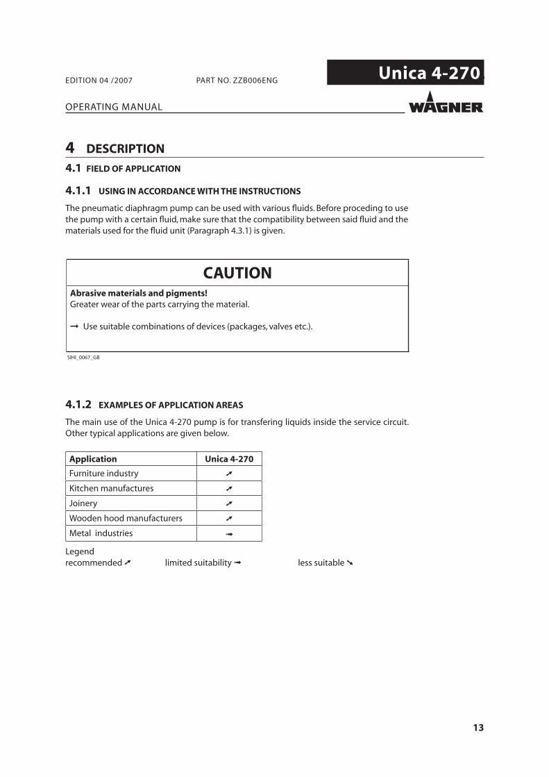
4.1.1 USING IN ACCORDANCE WITH THE INSTRUCTIONS
The pneumatic diaphragm pump can be used with various fl uids. Before proceding to use the pump with a certain fl uid, make sure that the compatibility between said fl uid and the materials used for the fl uid unit (Paragraph 4.3.1) is given.
4.1.2 EXAMPLES OF APPLICATION AREAS
The main use of the Unica 4-270 pump is for transfering liquids inside the service circuit. Other typical applications are given below.
Application Unica 4-270
Furniture industry ➚
Kitchen manufactures ➚
Joinery ➚
Wooden hood manufacturers ➚
Metal industries ➟
Legend recommended ➚ limited suitability ➟ less suitable ➘
14
Unica 4-270.
OPERATING MANUAL
EDITION 04 /2007 PART NO. ZZB006ENG
4.2 EXTENT OF DELIVERY
Double-diaphragm pneumatic pump composed of:
- Integrated pneumatic motor - Pumping stage
CE-conformity see Chapter 3.3Operating manual in english Part No.: ZZB006ENGOperating manual for the other language see Chapter 1.1
The delivery note shows the exact scope of delivery.Accessories: see chapter 7.
4.3 DATA
4.3.1 MATERIALS USED FOR COMPONENTS IN CONTACT WITH THE PRODUCT
Suction ducts Stainless steel EN 1.4301 (X 5 CrNi 18-10, AISI 304) Valves balls Stainless steel EN 1.4028 (X 30 Cr 13, AISI 420)Valves seats Stainless steel EN 1.4301 (X 5 CrNi 18-10, AISI 304)Valve bodies Acetal (POM)Diaphragms PTFEO-rings PTFE
15
Unica 4-270.
OPERATING MANUAL
EDITION 04 /2007 PART NO. ZZB006ENG
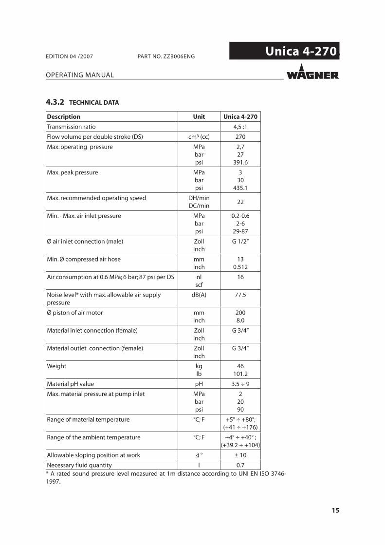
4.3.2 TECHNICAL DATA
Description Unit Unica 4-270
Transmission ratio 4,5 :1
Flow volume per double stroke (DS) cm³ (cc) 270
Max. operating pressure MPabarpsi
2,727
391.6
Max. peak pressure MPabarpsi
330
435.1
Max. recommended operating speed DH/minDC/min
22
Min. - Max. air inlet pressure MPabarpsi
0.2-0.62-6
29-87
Ø air inlet connection (male) ZollInch
G 1/2“
Min. Ø compressed air hose mmInch
130.512
Air consumption at 0.6 MPa; 6 bar; 87 psi per DS nlscf
16
Noise level* with max. allowable air supply pressure
dB(A) 77.5
Ø piston of air motor mmInch
2008.0
Material inlet connection (female) ZollInch
G 3/4“
Material outlet connection (female) ZollInch
G 3/4“
Weight kg lb
46101.2
Material pH value pH 3.5 ÷ 9
Max. material pressure at pump inlet MPabarpsi
22090
Range of material temperature °C; F +5° ÷ +80°; (+41 ÷ +176)
Range of the ambient temperature °C; F +4° ÷ +40° ; (+39.2 ÷ +104)
Allowable sloping position at work <) ° ± 10
Necessary fl uid quantity l 0.7* A rated sound pressure level measured at 1m distance according to UNI EN ISO 3746-1997.
16
Unica 4-270.
OPERATING MANUAL
EDITION 04 /2007 PART NO. ZZB006ENG
17
Unica 4-270.
A
B
C
D E G
F H
I
J
K
L
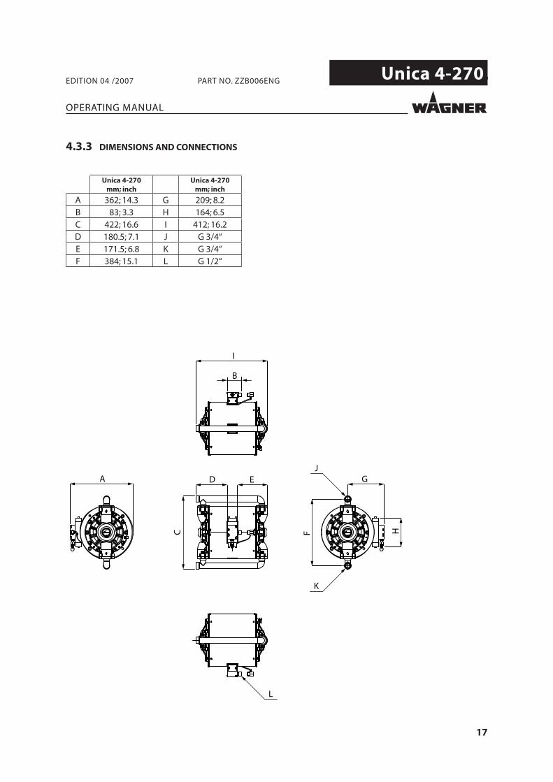
Unica 4-270mm; inch
Unica 4-270mm; inch
A 362; 14.3 G 209; 8.2B 83; 3.3 H 164; 6.5C 422; 16.6 I 412; 16.2D 180.5; 7.1 J G 3/4“E 171.5; 6.8 K G 3/4“F 384; 15.1 L G 1/2“
OPERATING MANUAL
EDITION 04 /2007 PART NO. ZZB006ENG
4.3.3 DIMENSIONS AND CONNECTIONS
18
Unica 4-270.
0
22.5 (2.25) <326>
15 (1.5) <218>
7.5 (0.75) <109>
0
10 20 30 40 50 60
750<26.5>
500<17.7>
250<8.8>
0 16.8 <4.44>
14.0 <3.70>
11.2 <2.96>
8.4 <2.22>
5.6<1.48>
2.8<0.74>
0
B
C
bar (MPa) <psi>
nl/min<scfm>
l/min<gpm>
A
B
C
30 (3) <435>
1000<35>
A
6 bar
4 bar
6 bar
4 bar
C_41_00003
2 bar2 bar
OPERATING MANUAL
EDITION 04 /2007 PART NO. ZZB006ENG
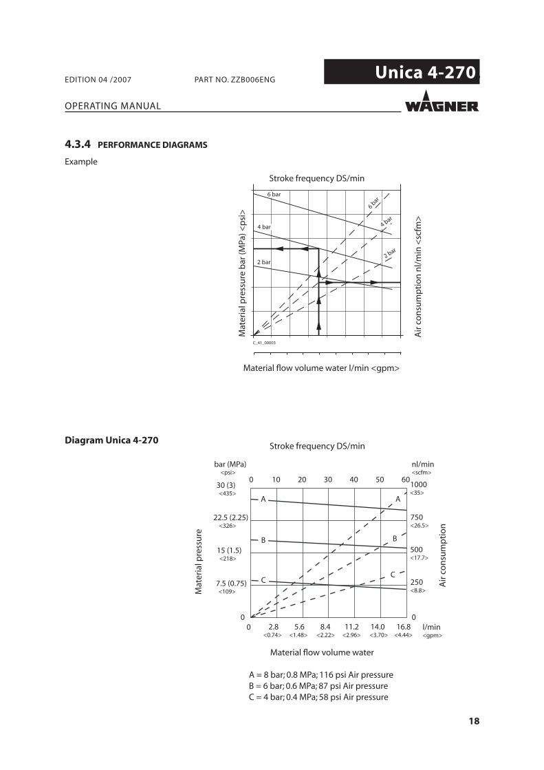
Diagram Unica 4-270Stroke frequency DS/min
Mat
eria
l pre
ssu
re
Air
co
nsu
mp
tio
n
Material fl ow volume water
A = 8 bar; 0.8 MPa; 116 psi Air pressureB = 6 bar; 0.6 MPa; 87 psi Air pressureC = 4 bar; 0.4 MPa; 58 psi Air pressure
4.3.4 PERFORMANCE DIAGRAMS
Example
Stroke frequency DS/min
Mat
eria
l pre
ssu
re b
ar (M
Pa) <
psi
>
Material fl ow volume water l/min <gpm>
Air
co
nsu
mp
tio
n n
l/m
in <
scfm
>
19
Unica 4-270.
6
8
9
4
3
1
2
5
7
10
OPERATING MANUAL
EDITION 04 /2007 PART NO. ZZB006ENG
4.4 FUNCTIONING
4.4.1 PUMP
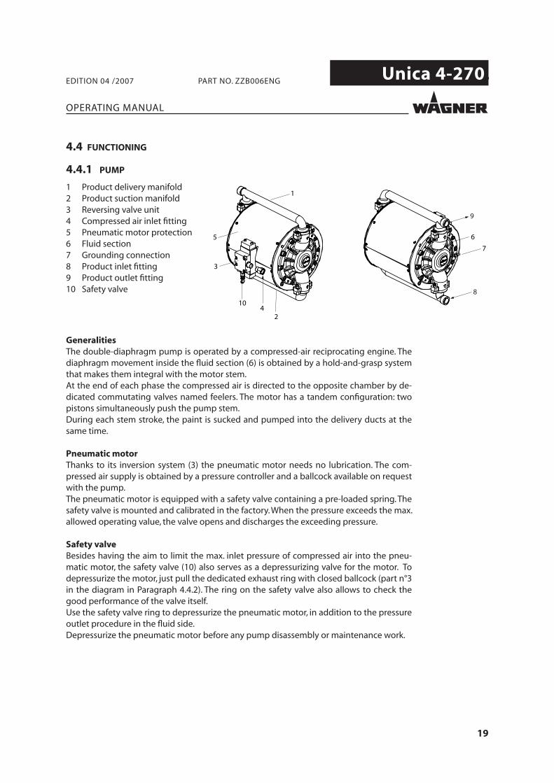
1 Product delivery manifold2 Product suction manifold3 Reversing valve unit4 Compressed air inlet fi tting5 Pneumatic motor protection6 Fluid section7 Grounding connection8 Product inlet fi tting9 Product outlet fi tting10 Safety valve
GeneralitiesThe double-diaphragm pump is operated by a compressed-air reciprocating engine. The diaphragm movement inside the fl uid section (6) is obtained by a hold-and-grasp system that makes them integral with the motor stem.At the end of each phase the compressed air is directed to the opposite chamber by de-dicated commutating valves named feelers. The motor has a tandem confi guration: two pistons simultaneously push the pump stem.During each stem stroke, the paint is sucked and pumped into the delivery ducts at the same time.
Pneumatic motorThanks to its inversion system (3) the pneumatic motor needs no lubrication. The com-pressed air supply is obtained by a pressure controller and a ballcock available on request with the pump.The pneumatic motor is equipped with a safety valve containing a pre-loaded spring. The safety valve is mounted and calibrated in the factory. When the pressure exceeds the max. allowed operating value, the valve opens and discharges the exceeding pressure.
Safety valveBesides having the aim to limit the max. inlet pressure of compressed air into the pneu-matic motor, the safety valve (10) also serves as a depressurizing valve for the motor. To depressurize the motor, just pull the dedicated exhaust ring with closed ballcock (part n°3 in the diagram in Paragraph 4.4.2). The ring on the safety valve also allows to check the good performance of the valve itself.Use the safety valve ring to depressurize the pneumatic motor, in addition to the pressure outlet procedure in the fl uid side.Depressurize the pneumatic motor before any pump disassembly or maintenance work.
20
Unica 4-270.
OPERATING MANUAL
EDITION 04 /2007 PART NO. ZZB006ENG
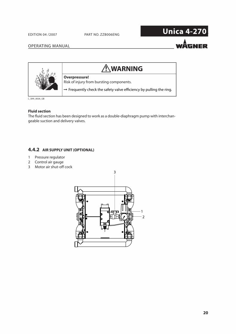
4.4.2 AIR SUPPLY UNIT (OPTIONAL)
1 Pressure regulator2 Control air gauge3 Motor air shut-off cock
3
1
2
Fluid section The fl uid section has been designed to work as a double-diaphragm pump with interchan-geable suction and delivery valves.
WARNINGOverpressure!Risk of injury from bursting components.
C_SIHI_0026_GB
Frequently check the safety valve efficiency by pulling the ring.
21
Unica 4-270.
OPERATING MANUAL
EDITION 04 /2007 PART NO. ZZB006ENG
5 STARTING UP AND OPERATING
5.1 INSTALLATION AND CONNECTION
The Unica 4-270 diaphragm pum can be wall-mounted or fl oor-mounted.For a diagram of the tipical installations, see Paragraph 5.1.6. The diagram does not represent the most suitable solution in all situations and is given as mere example. Please apply to a Wagner authorised engineer for further information about the best mounting solution for each user’s special needs.To make pump operation and maintenance easier install the device so that the pneumatic supply inlet and the pneumatic supply/suction fi ttings of the pump are easily accessible.Install the pump in a horizontal position.For support to integrate the pump in a pre-existing plant or for a customised location, please apply to a Wagner authorised engineer.Always use original Wagner spare parts.
5.1.1 PUMP WALL-INSTALLATION
The Unica 4-270 pump installation kit for wall-mounting can be supplied on request.I
Part number:Wall mounting kit: T6151.00
For information regarding the kit contents and assembling, please see the relevant para-graph in chapter 7 - Accessories.
5.1.2 PUMP INSTALLATION ON GROUND FRAME
The Unica 4-270 pump installation kit on a ground frame can be supplied on request.
Part number:Ground frame kit: T6148.00
For information regarding the kit contents and assembling, please see the relevant para-graph in chapter 7 - Accessories.
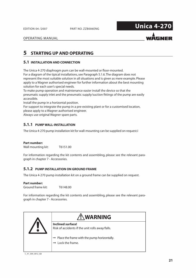
C_41_SIHI_0012_GB
WARNINGInclined surface!Risk of accidents if the unit rolls away/falls.
Place the frame with the pump horizontally.
Lock the frame.
22
Unica 4-270.
OPERATING MANUAL
EDITION 04 /2007 PART NO. ZZB006ENG
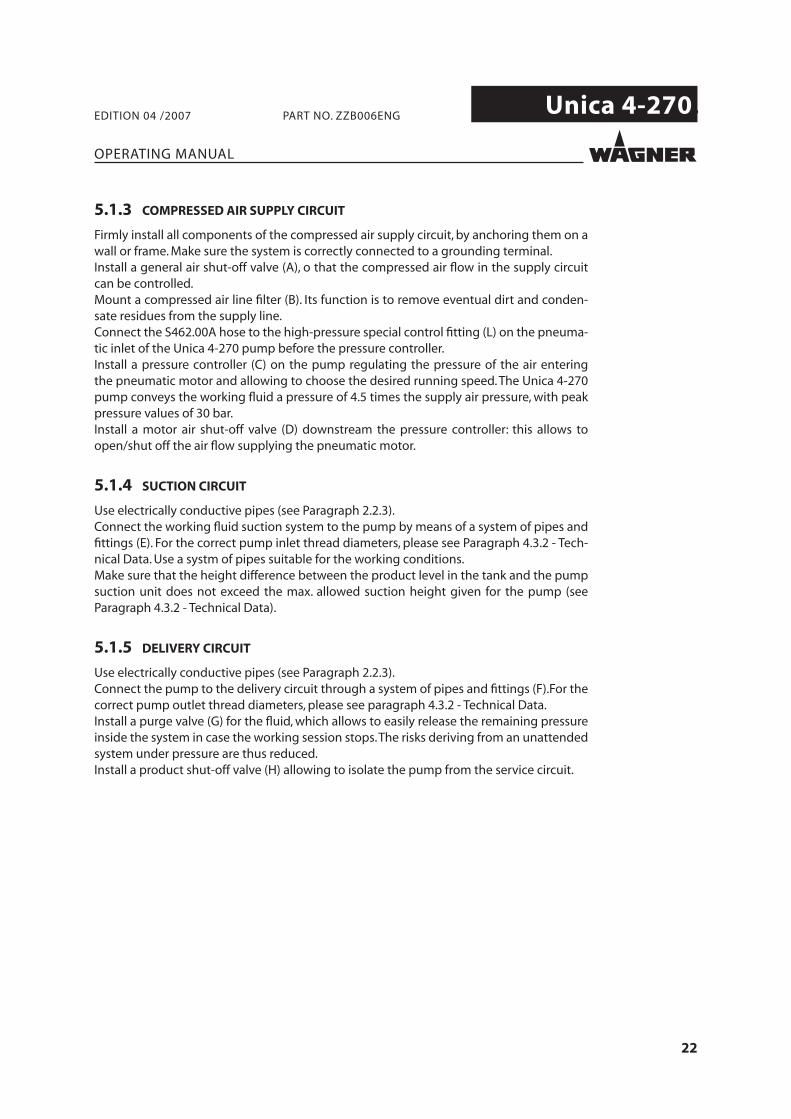
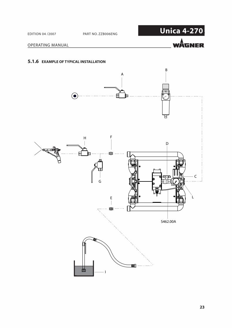
5.1.3 COMPRESSED AIR SUPPLY CIRCUIT
Firmly install all components of the compressed air supply circuit, by anchoring them on a wall or frame. Make sure the system is correctly connected to a grounding terminal.Install a general air shut-off valve (A), o that the compressed air fl ow in the supply circuit can be controlled.Mount a compressed air line fi lter (B). Its function is to remove eventual dirt and conden-sate residues from the supply line.Connect the S462.00A hose to the high-pressure special control fi tting (L) on the pneuma-tic inlet of the Unica 4-270 pump before the pressure controller. Install a pressure controller (C) on the pump regulating the pressure of the air entering the pneumatic motor and allowing to choose the desired running speed. The Unica 4-270 pump conveys the working fl uid a pressure of 4.5 times the supply air pressure, with peak pressure values of 30 bar.Install a motor air shut-off valve (D) downstream the pressure controller: this allows to open/shut off the air fl ow supplying the pneumatic motor.
5.1.4 SUCTION CIRCUIT
Use electrically conductive pipes (see Paragraph 2.2.3).Connect the working fl uid suction system to the pump by means of a system of pipes and fi ttings (E). For the correct pump inlet thread diameters, please see Paragraph 4.3.2 - Tech-nical Data. Use a systm of pipes suitable for the working conditions.Make sure that the height difference between the product level in the tank and the pump suction unit does not exceed the max. allowed suction height given for the pump (see Paragraph 4.3.2 - Technical Data).
5.1.5 DELIVERY CIRCUIT
Use electrically conductive pipes (see Paragraph 2.2.3).Connect the pump to the delivery circuit through a system of pipes and fi ttings (F).For the correct pump outlet thread diameters, please see paragraph 4.3.2 - Technical Data.Install a purge valve (G) for the fl uid, which allows to easily release the remaining pressure inside the system in case the working session stops. The risks deriving from an unattended system under pressure are thus reduced.Install a product shut-off valve (H) allowing to isolate the pump from the service circuit.
23
Unica 4-270.
OPERATING MANUAL
EDITION 04 /2007 PART NO. ZZB006ENG
5.1.6 EXAMPLE OF TYPICAL INSTALLATION
F
BA
E
C
D
H
G
S462.00A
L
I
24
Unica 4-270.
C_41_00007
R max < 1 M Ω
OPERATING MANUAL
EDITION 04 /2007 PART NO. ZZB006ENG
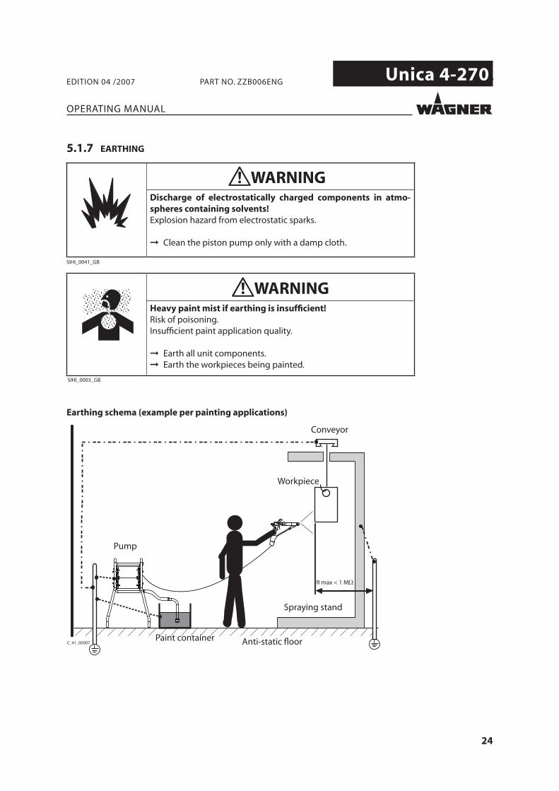
5.1.7 EARTHING
Earthing schema (example per painting applications)
Paint container
Workpiece
Conveyor
Anti-static fl oor
Pump
Spraying stand
25
Unica 4-270.
OPERATING MANUAL
EDITION 04 /2007 PART NO. ZZB006ENG
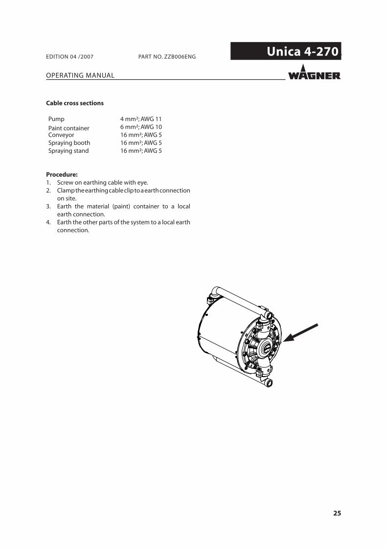
Cable cross sections
Pump 4 mm²; AWG 11
Paint container 6 mm²; AWG 10Conveyor 16 mm²; AWG 5Spraying booth 16 mm²; AWG 5Spraying stand 16 mm²; AWG 5
Procedure:1. Screw on earthing cable with eye.2. Clamp the earthing cable clip to a earth connection
on site.3. Earth the material (paint) container to a local
earth connection.4. Earth the other parts of the system to a local earth
connection.
26
Unica 4-270.
OPERATING MANUAL
EDITION 04 /2007 PART NO. ZZB006ENG
5.2 START UP
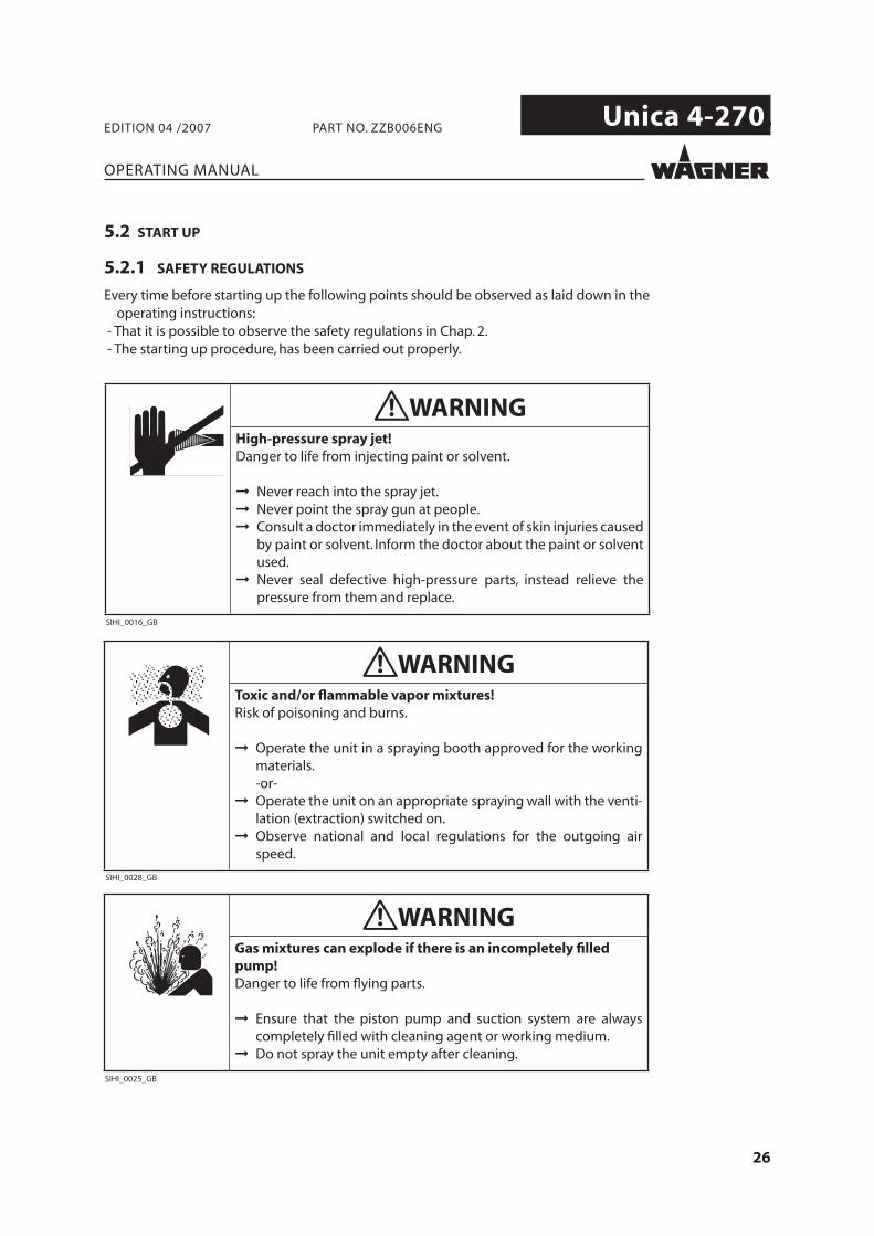
5.2.1 SAFETY REGULATIONS
Every time before starting up the following points should be observed as laid down in the operating instructions:
- That it is possible to observe the safety regulations in Chap. 2. - The starting up procedure, has been carried out properly.
27
Unica 4-270.
OPERATING MANUAL
EDITION 04 /2007 PART NO. ZZB006ENG
Before every start-up, the following points should be observed as laid down in the operating manual: - Check the permissible pressures - Check all connections for leaks - Check hose for damage
It should be ensured that the unit is in the following state before carrying out any work on it:- Interrupt compressed air supply.- Depressurise the pump and the product delivery circuit.
Emergency stop In case of unexpected events, it is necessary to immediately close the compressed air sup-ply and discharge the pressure from the pump service circuit.
28
Unica 4-270.
OPERATING MANUAL
EDITION 04 /2007 PART NO. ZZB006ENG
5.2.2 PRESSURE RELEASE PROCEDURE
1. Interrupt the pump compressed air supply.2. Open the usage and discharge the remaining pressure inside the pump and circuit.3. To guarantee a complete depressurisation of the pneumatic motor, pull the ring on the
safety valve (see Paragraph 4.4.1).
5.2.4 FILLING WITH WORKING FLUID
In this description reference is made to the exemplifying diagram given in Paragraph 5.1.6.1. Make sure the pump is correctly connected to a grounding terminal. Please see
Pragraph 5.1.7 - “Grounding” for further informaion.2. Check the tightness of all fi ttings and make sure they are tight enough. 3. Connect the pump suction duct to the tank with the working fl uid (I). For example, if a
drip-in pipe is used, dip it in the barrel of the product to be pumped.4. Connect the pump delivery duct to the usage. If a washing is in progress, direct the
product outlet pipe into the container collecting the solvent.5. Close the pump air pressure controller (C) , pressurise the compressed air supply line
and open the air shut-off valve on the pump (D).6. Slowly open the air pressure controller on the pump (C) until it starts to work. Have the
pump work slowly until all the air left inside the suction and delivery circuits has been discharged. Continue until the pump has correctly primed.
7. Only if the pump is being washed with solvent, have it cycle until the clean solvent fl ows inside the delivery circuit. Then close the pump air pressure controller (C).
5.2.3 PUMP WASHING
The Unica 4-270 pump is tested in the factory with oil.In case eventual testing fl uid residues may contaminate the working material, carry out a preliminary washing using a solvent compliant with the product. To perform the washing follow the instructions in the following paragraph, considering the solvent instead of the working material.
5.2.5 PUMP STOP
For a short-term stop, perform the pressure release procedure (Paragraph 5.2.2).
For a permanent stop, such as for example an overnight standstill:1. Clean the pump fl uid section by washing it with a compliant solvent.2. Leave the solvent inside the pump fl uid section.3. Perform the pressure release procedure (Paragraph 5.2.2).
For a stop preceding maintenance or disconnection of the pump, see the instructions given in Paragraph 5.3.
29
Unica 4-270.
OPERATING MANUAL
EDITION 04 /2007 PART NO. ZZB006ENG
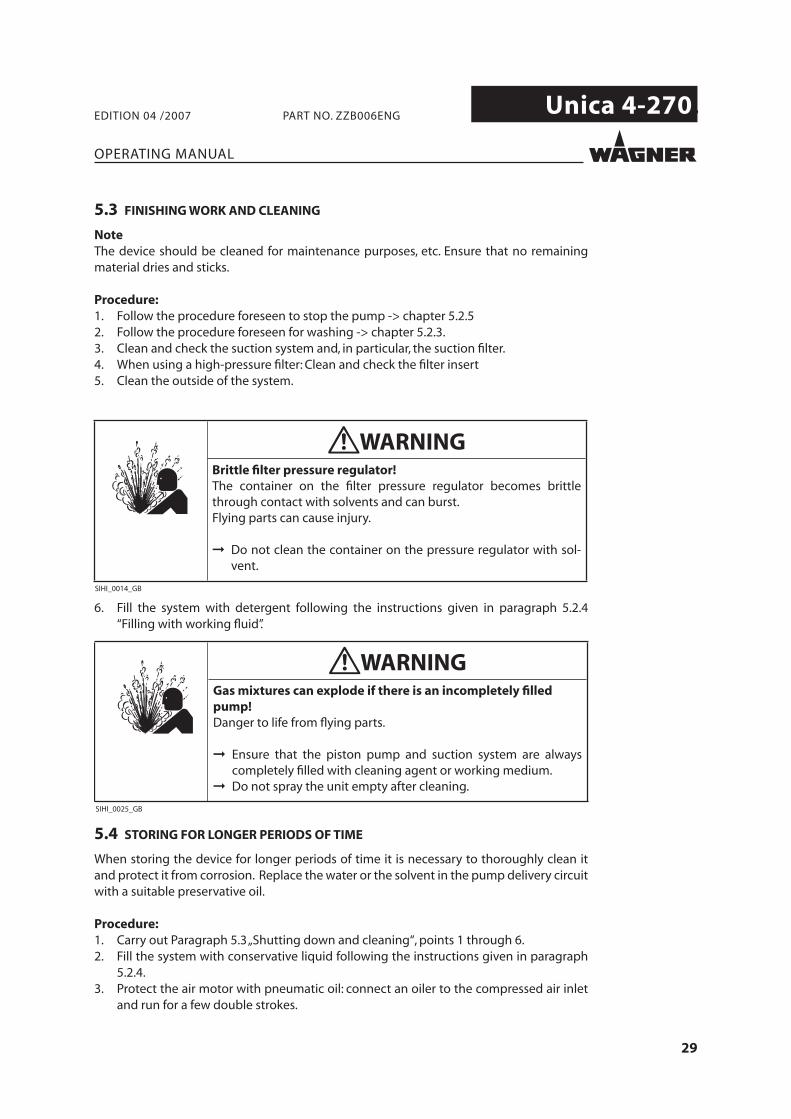
5.3 FINISHING WORK AND CLEANING
NoteThe device should be cleaned for maintenance purposes, etc. Ensure that no remaining material dries and sticks.
Procedure:1. Follow the procedure foreseen to stop the pump -> chapter 5.2.52. Follow the procedure foreseen for washing -> chapter 5.2.3.3. Clean and check the suction system and, in particular, the suction fi lter.4. When using a high-pressure fi lter: Clean and check the fi lter insert5. Clean the outside of the system.
6. Fill the system with detergent following the instructions given in paragraph 5.2.4 “Filling with working fl uid”.
5.4 STORING FOR LONGER PERIODS OF TIME
When storing the device for longer periods of time it is necessary to thoroughly clean it and protect it from corrosion. Replace the water or the solvent in the pump delivery circuit with a suitable preservative oil.
Procedure:1. Carry out Paragraph 5.3 „Shutting down and cleaning“, points 1 through 6.2. Fill the system with conservative liquid following the instructions given in paragraph
5.2.4.3. Protect the air motor with pneumatic oil: connect an oiler to the compressed air inlet
and run for a few double strokes.
30
Unica 4-270.
OPERATING MANUAL
EDITION 04 /2007 PART NO. ZZB006ENG
6 FAULT LOCATION, MAINTENANCE AND REPAIR
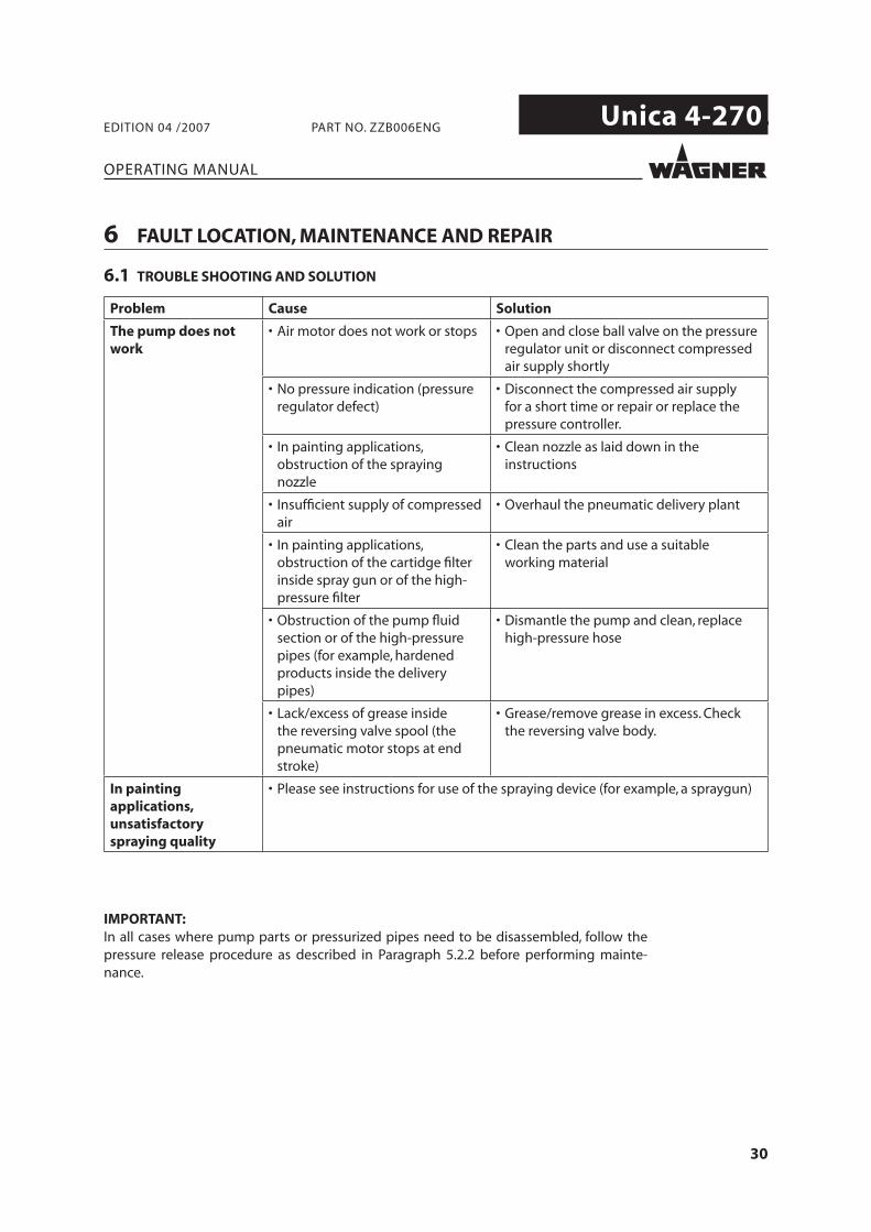
6.1 TROUBLE SHOOTING AND SOLUTION
Problem Cause Solution
The pump does not work
• Air motor does not work or stops • Open and close ball valve on the pressure regulator unit or disconnect compressed air supply shortly
• No pressure indication (pressure regulator defect)
• Disconnect the compressed air supply for a short time or repair or replace the pressure controller.
• In painting applications, obstruction of the spraying nozzle
• Clean nozzle as laid down in the instructions
• Insuffi cient supply of compressed air
• Overhaul the pneumatic delivery plant
• In painting applications, obstruction of the cartidge fi lter inside spray gun or of the high-pressure fi lter
• Clean the parts and use a suitable working material
• Obstruction of the pump fl uid section or of the high-pressure pipes (for example, hardened products inside the delivery pipes)
• Dismantle the pump and clean, replace high-pressure hose
• Lack/excess of grease inside the reversing valve spool (the pneumatic motor stops at end stroke)
• Grease/remove grease in excess. Check the reversing valve body.
In painting applications, unsatisfactory spraying quality
• Please see instructions for use of the spraying device (for example, a spraygun)
IMPORTANT:In all cases where pump parts or pressurized pipes need to be disassembled, follow the pressure release procedure as described in Paragraph 5.2.2 before performing mainte-nance.
31
Unica 4-270.
OPERATING MANUAL
EDITION 04 /2007 PART NO. ZZB006ENG
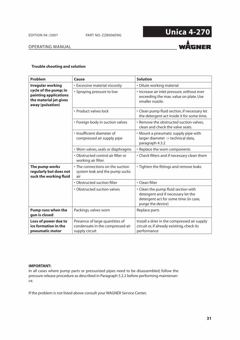
Problem Cause Solution
Irregular working cycle of the pump; in painting applications the material jet gives away (pulsation)
• Excessive material viscosity • Dilute working material
• Spraying pressure to low • Increase air inlet pressure, without ever exceeding the max. value on plate. Use smaller nozzle.
• Product valves lock • Clean pump fl uid section, if necessary let the detergent act inside it for some time.
• Foreign body in suction valves • Remove the obstructed suction valves, clean and check the valve seats.
• Insuffi cient diameter of compressed air supply pipe
• Mount a pneumatic supply pipe with larger diameter -> technical data, paragraph 4.3.2
• Worn valves, seals or diaphragms • Replace the worn components
• Obstructed control air fi lter or working air fi lter.
• Check fi lters and if necessary clean them
The pump works regularly but does not suck the working fl uid
• The connections on the suction system leak and the pump sucks air
• Tighten the fi ttings and remove leaks
• Obstructed suction fi lter • Clean fi lter
• Obstructed suction valves • Clean the pump fl uid section with detergent and if necessary let the detergent act for some time (in case, purge the device)
Pump runs when the gun is closed
Packings, valves worn Replace parts
Loss of power due to ice formation in the pneumatic motor
Presence of large quantities of condensate in the compressed air supply circuit
Install a drier in the compressed air supply circuit or, if already existinig, check its performance
Trouble shooting and solution
IMPORTANT:In all cases where pump parts or pressurized pipes need to be disassembled, follow the pressure release procedure as described in Paragraph 5.2.2 before performing maintenan-ce.
If the problem is not listed above consult your WAGNER Service Center.
32
Unica 4-270.
OPERATING MANUAL
EDITION 04 /2007 PART NO. ZZB006ENG
6.2 MAINTENANCE
6.2.1 LUBRICATION
No lubrication is required for the pneumatic motor. An excessive lubrication may cause system failure.Regularly check the condition of compressed air fi lters mounted on the pneumatic motor pilot system (parts nr. 25 in the diagram in Paragraph 8.3). Replace them if necessary.
6.2.2 WASHING AND STORING
Before stopping the pump for a period of time in which the fl uid may harden inside the curcuit and damage the system, carry out a washing with compliant solvent. Please see Paragraph 5.3 “Disconnection and cleaning” for the relevant procedure.
6.2.3 REGULAR CHECK OF SEALING AND TIGHTNESS
Before each usage of the pump:1. Make sure that all fl uid conveying pipes have no wear signs o damages. Replace them
if necessary.2. Check sealing and tightness of all threaded fi ttings. Make sure there are no leaks.
Check screws tightness at least once every two months. Please see this manual for information about the correct tightening torques.
6.2.4 PLAN OF PREVENTIVE MAINTENANCE
Work out a plan of preventive maintenance including the above checks, basing on the usage history of the pump. The wear of components depends on the using conditions. It is important to replace the parts subject to wear (e.g. valve seats or membranes) in due time, in order not to have the system damaged, which can be avoided by means of a plan of preventive maintenance.
33
Unica 4-270.
OPERATING MANUAL
EDITION 04 /2007 PART NO. ZZB006ENG
6.3 PUMP REPAIR
Before carrying out any maintenance measure:1. Possibly wash the pump fl uid section(see Paragraph 5.2.3)2. Release the pressure inside the pump following the procedure described in Paragraph
5.2.2.3. Disconnect the pump from the compressed air supply line and disconnect the fl uid
section from the external suction and service circuits.4. Remove the pump from the installation site and take it to a suitable place for the
maintenance work.
How to carry out a repair Ordinary and extraordinary maintenance is to be carried out according to the schemes and procedures given in this manual for Use and Maintenance,In all cases:1. Apply to a Wagner authorised engineer.2. Use only Wagner original spare parts.3. Before assembling parts, make sure they are clean and, if necessary, lubricated.4. Avoid damaging gasket sealing surfaces during maintenance.5. Whenever the pump is assembled, replace all o-rings in the fl uid section whcih have
already been subject to previous tightening.6. Avoid using silicone-based or silicone-contanining lubricants.
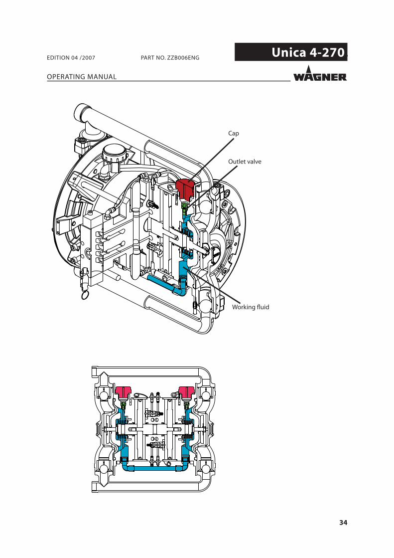
6.3.1 MAINTENANCE OF THE HYDRAULIC CIRCUIT
The Unica 4-270 pump includes a fl uid-mechanical conservation system granting the best possible performance of the diaphragms under normal working conditions.The hydraulic circuit is normally full of working fl uid fi lled in the factory. The safety card of the working fl uid can be supplied on requestBefore carrying out any maintenance involving the hydraulic circuit, the working fl uid is to be extracted as described in Paragraph 6.3.1.1.The quantity of working fl uid necessary to fi ll the circuit is about 1 l. It is advisable to use only Wagner spare fl uid:
Order numberHydraulic fl uid Unica 4-270 pump (1-litre bottle) Z126.00
The fl uid-mechanical system inside the hydraulic circuit needs no maintenance and the circuit doesn’t usually need disassembling. The need to disassemble it may arise in case it is necessary to add parts inside the pump which are subject to maintenance.If lacking Wagner spare fl uid after carrying out the maintenance, it is possible to tempo-rarily fi ll the hydraulic circuit with water; however, it is advisable to replace it with Wagner working fl uid soonest possible. For further information please apply to a Wagner authori-sed engineer.
An explanatory picture is given below.
The assembling diagram of the hydraulic circuit is given in Paragraph 8.4.
34
Unica 4-270.
OPERATING MANUAL
EDITION 04 /2007 PART NO. ZZB006ENG
Cap
Outlet valve
Working fl uid
35
Unica 4-270.
11
12
CD
OPERATING MANUAL
EDITION 04 /2007 PART NO. ZZB006ENG
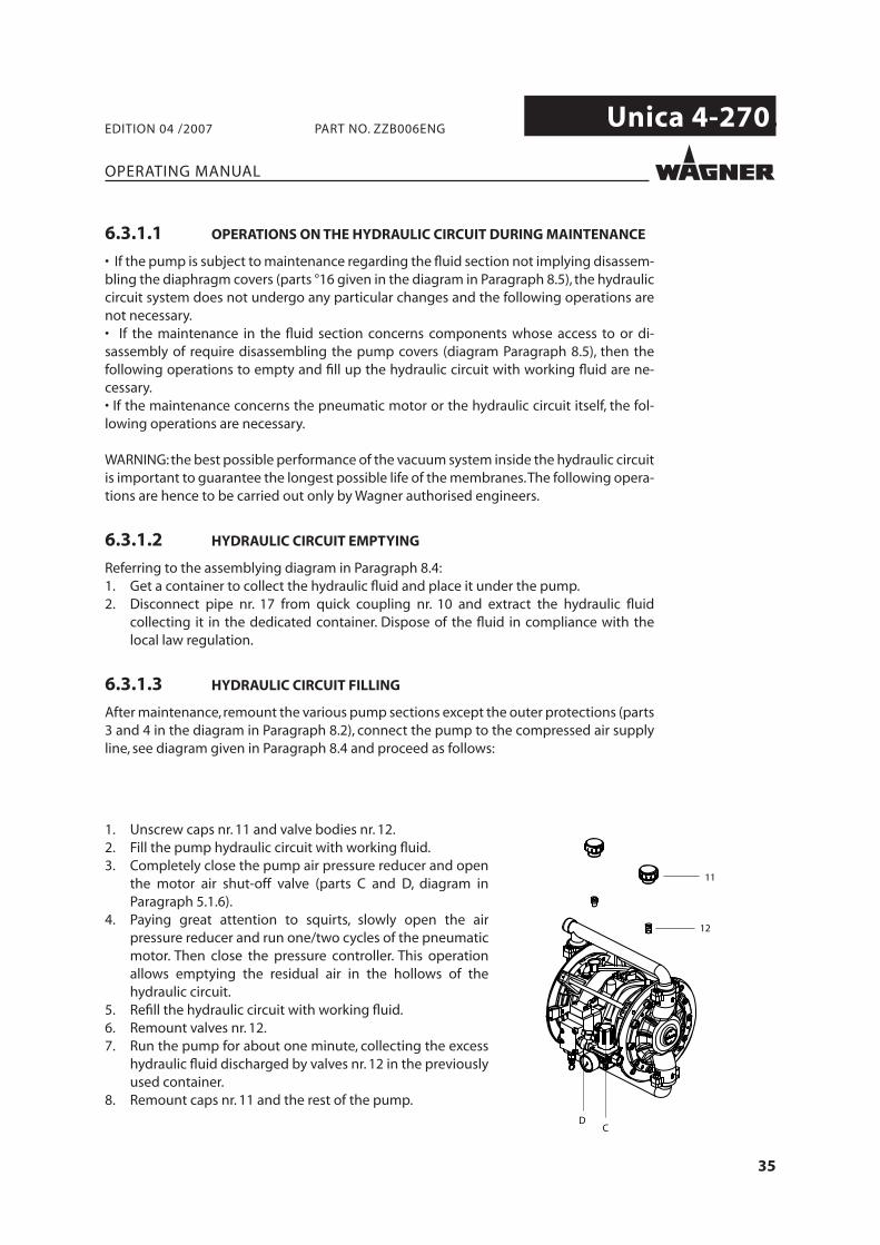
1. Unscrew caps nr. 11 and valve bodies nr. 12.2. Fill the pump hydraulic circuit with working fl uid.3. Completely close the pump air pressure reducer and open
the motor air shut-off valve (parts C and D, diagram in Paragraph 5.1.6).
4. Paying great attention to squirts, slowly open the air pressure reducer and run one/two cycles of the pneumatic motor. Then close the pressure controller. This operation allows emptying the residual air in the hollows of the hydraulic circuit.
5. Refi ll the hydraulic circuit with working fl uid.6. Remount valves nr. 12.7. Run the pump for about one minute, collecting the excess
hydraulic fl uid discharged by valves nr. 12 in the previously used container.
8. Remount caps nr. 11 and the rest of the pump.
6.3.1.1 OPERATIONS ON THE HYDRAULIC CIRCUIT DURING MAINTENANCE
• If the pump is subject to maintenance regarding the fl uid section not implying disassem-bling the diaphragm covers (parts °16 given in the diagram in Paragraph 8.5), the hydraulic circuit system does not undergo any particular changes and the following operations are not necessary.• If the maintenance in the fl uid section concerns components whose access to or di-sassembly of require disassembling the pump covers (diagram Paragraph 8.5), then the following operations to empty and fi ll up the hydraulic circuit with working fl uid are ne-cessary.• If the maintenance concerns the pneumatic motor or the hydraulic circuit itself, the fol-lowing operations are necessary.
WARNING: the best possible performance of the vacuum system inside the hydraulic circuit is important to guarantee the longest possible life of the membranes. The following opera-tions are hence to be carried out only by Wagner authorised engineers.
6.3.1.2 HYDRAULIC CIRCUIT EMPTYING
Referring to the assemblying diagram in Paragraph 8.4:1. Get a container to collect the hydraulic fl uid and place it under the pump.2. Disconnect pipe nr. 17 from quick coupling nr. 10 and extract the hydraulic fl uid
collecting it in the dedicated container. Dispose of the fl uid in compliance with the local law regulation.
6.3.1.3 HYDRAULIC CIRCUIT FILLING
After maintenance, remount the various pump sections except the outer protections (parts 3 and 4 in the diagram in Paragraph 8.2), connect the pump to the compressed air supply line, see diagram given in Paragraph 8.4 and proceed as follows:
36
Unica 4-270.
4
3
12
OPERATING MANUAL
EDITION 04 /2007 PART NO. ZZB006ENG
7 ACCESSORIES
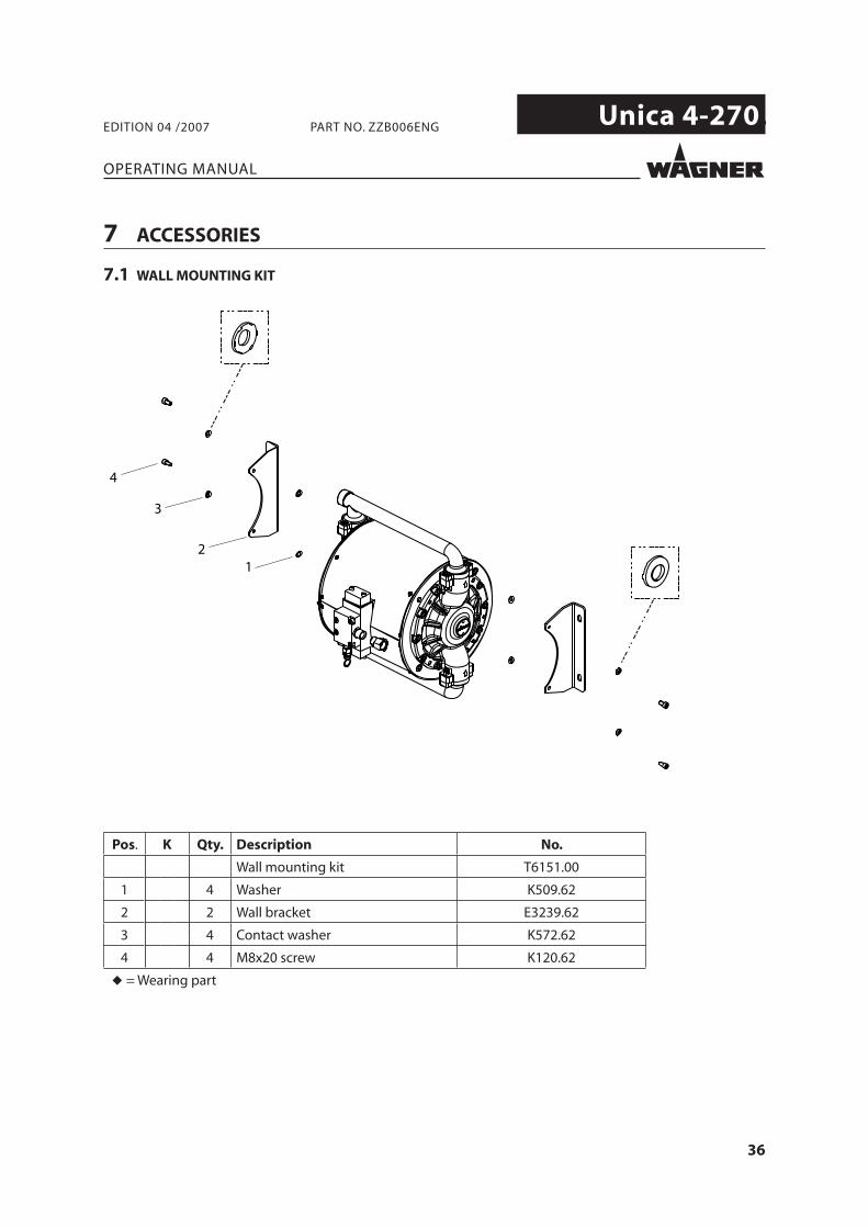
7.1 WALL MOUNTING KIT
Pos. K Qty. Description No.
Wall mounting kit T6151.00
1 4 Washer K509.62
2 2 Wall bracket E3239.62
3 4 Contact washer K572.62
4 4 M8x20 screw K120.62
◆ = Wearing part
37
Unica 4-270.
OPERATING MANUAL
EDITION 04 /2007 PART NO. ZZB006ENG
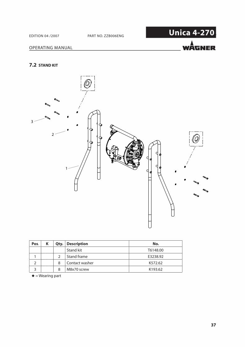
7.2 STAND KIT
3
1
2
Pos. K Qty. Description No.
Stand kit T6148.00
1 2 Stand frame E3238.92
2 8 Contact washer K572.62
3 8 M8x70 screw K193.62
◆ = Wearing part
38
Unica 4-270.
4
31
2
5
6
OPERATING MANUAL
EDITION 04 /2007 PART NO. ZZB006ENG
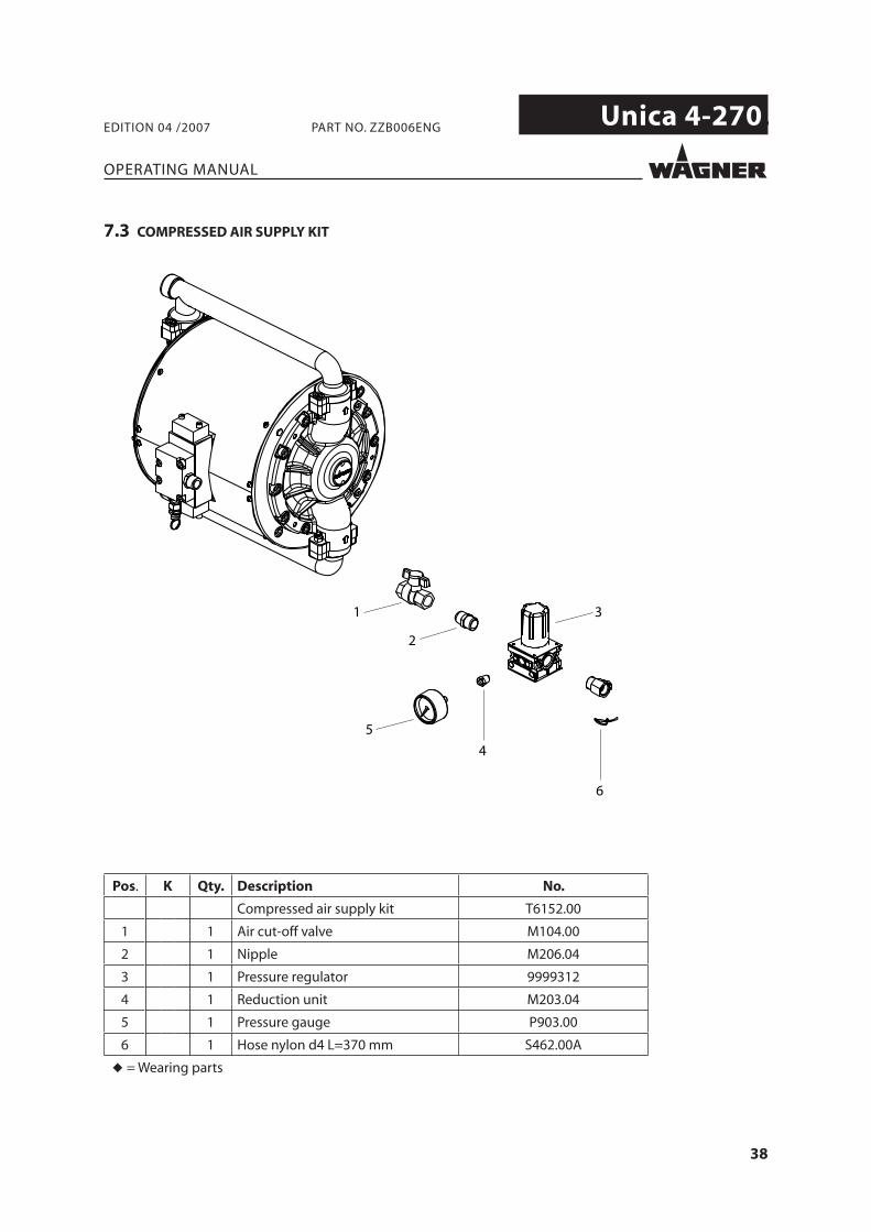
7.3 COMPRESSED AIR SUPPLY KIT
Pos. K Qty. Description No.
Compressed air supply kit T6152.00
1 1 Air cut-off valve M104.00
2 1 Nipple M206.04
3 1 Pressure regulator 9999312
4 1 Reduction unit M203.04
5 1 Pressure gauge P903.00
6 1 Hose nylon d4 L=370 mm S462.00A
◆ = Wearing parts
39
Unica 4-270.
OPERATING MANUAL
EDITION 04 /2007 PART NO. ZZB006ENG
8 SPARE PARTS
8.1 HOW TO ORDER SPARE PARTS
40
Unica 4-270.
OPERATING MANUAL
EDITION 04 /2007 PART NO. ZZB006ENG
41
Unica 4-270.
1
1
1
1
1
1
1
2 (*)
2 (**)
2 (*)
2 (**)
(*) (**)3
4
1
OPERATING MANUAL
EDITION 04 /2007 PART NO. ZZB006ENG
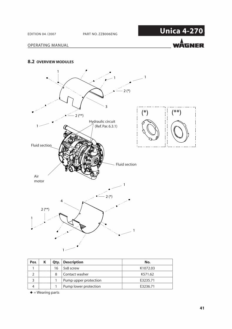
8.2 OVERVIEW MODULES
Hydraulic circuit (Ref. Par. 6.3.1)
Fluid section
Fluid section
Airmotor
Pos. K Qty. Description No.
1 16 5x8 screw K1072.03
2 8 Contact washer K571.62
3 1 Pump upper protection E3235.71
4 1 Pump lower protection E3236.71
◆ = Wearing parts
42
Unica 4-270.
20 a)50 Nm; 37 lbft
(*)
(**)(***)
19(**)
21
43 a)
64
7
15
14
14
14(*)
2415 Nm; 11.1 lbft
19(***)
8
13
10
12
11
9
23
16
7
1415
14
22
2415 Nm; 11.1 lbft
2217
18
2118
5 a) 3 a)
1
20 a)50 Nm; 37 lbft
2
6
4
25
23
14+15
14+15
14+15 25+14+22
25+16+22+2214+15
18+17
18+21
4
26
27
28
OPERATING MANUAL
EDITION 04 /2007 PART NO. ZZB006ENG
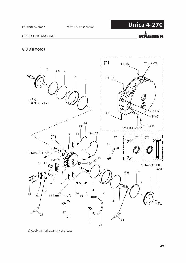
8.3 AIR MOTOR
a) Apply a small quantity of grease
43
Unica 4-270.
OPERATING MANUAL
EDITION 04 /2007 PART NO. ZZB006ENG
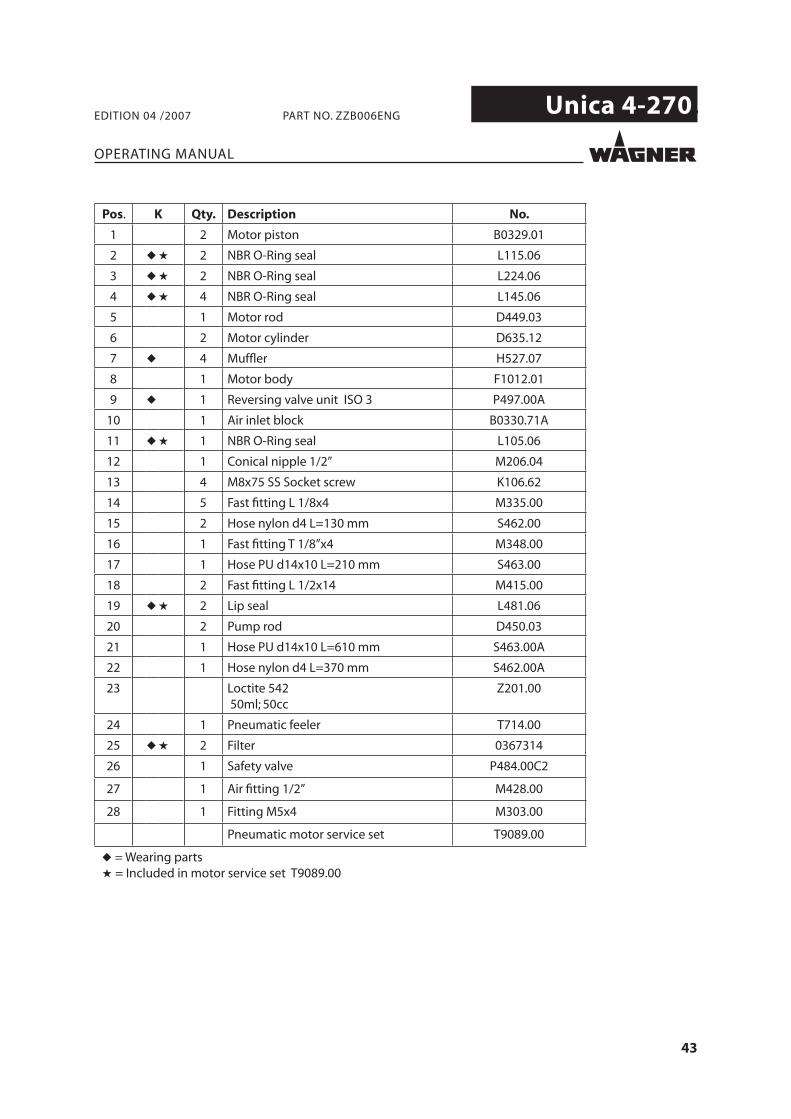
Pos. K Qty. Description No.
1 2 Motor piston B0329.01
2 ◆ ★ 2 NBR O-Ring seal L115.06
3 ◆ ★ 2 NBR O-Ring seal L224.06
4 ◆ ★ 4 NBR O-Ring seal L145.06
5 1 Motor rod D449.03
6 2 Motor cylinder D635.12
7 ◆ 4 Muffl er H527.07
8 1 Motor body F1012.01
9 ◆ 1 Reversing valve unit ISO 3 P497.00A
10 1 Air inlet block B0330.71A
11 ◆ ★ 1 NBR O-Ring seal L105.06
12 1 Conical nipple 1/2” M206.04
13 4 M8x75 SS Socket screw K106.62
14 5 Fast fi tting L 1/8x4 M335.00
15 2 Hose nylon d4 L=130 mm S462.00
16 1 Fast fi tting T 1/8”x4 M348.00
17 1 Hose PU d14x10 L=210 mm S463.00
18 2 Fast fi tting L 1/2x14 M415.00
19 ◆ ★ 2 Lip seal L481.06
20 2 Pump rod D450.03
21 1 Hose PU d14x10 L=610 mm S463.00A
22 1 Hose nylon d4 L=370 mm S462.00A
23 Loctite 542 50ml; 50cc
Z201.00
24 1 Pneumatic feeler T714.00
25 ◆ ★ 2 Filter 0367314
26 1 Safety valve P484.00C2
27 1 Air fi tting 1/2” M428.00
28 1 Fitting M5x4 M303.00
Pneumatic motor service set T9089.00
◆ = Wearing parts★ = Included in motor service set T9089.00
44
Unica 4-270.
4
6
8
3
1
9
2
5
7
10
OPERATING MANUAL
EDITION 04 /2007 PART NO. ZZB006ENG
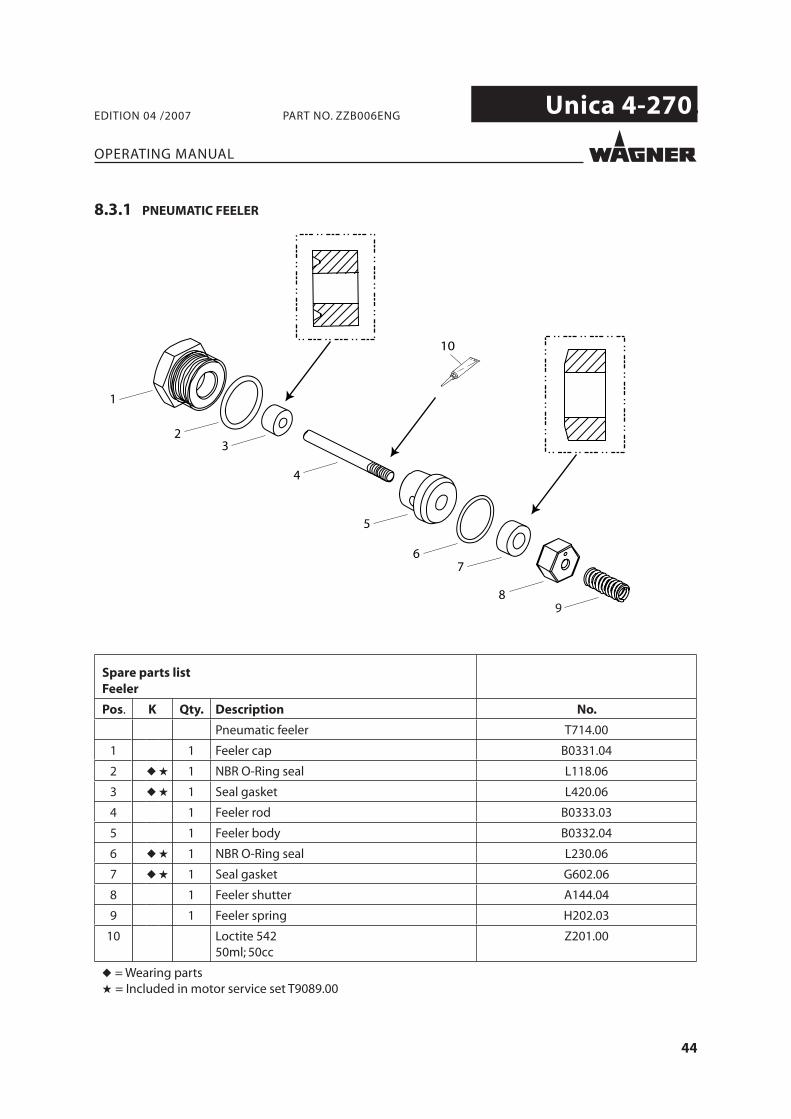
8.3.1 PNEUMATIC FEELER
Spare parts listFeeler
Pos. K Qty. Description No.
Pneumatic feeler T714.00
1 1 Feeler cap B0331.04
2 ◆ ★ 1 NBR O-Ring seal L118.06
3 ◆ ★ 1 Seal gasket L420.06
4 1 Feeler rod B0333.03
5 1 Feeler body B0332.04
6 ◆ ★ 1 NBR O-Ring seal L230.06
7 ◆ ★ 1 Seal gasket G602.06
8 1 Feeler shutter A144.04
9 1 Feeler spring H202.03
10 Loctite 54250ml; 50cc
Z201.00
◆ = Wearing parts★ = Included in motor service set T9089.00
45
Unica 4-270.
1
C_41_00022
2
3
45
67
8
9
12
10
3
11
1
6
13
OPERATING MANUAL
EDITION 04 /2007 PART NO. ZZB006ENG
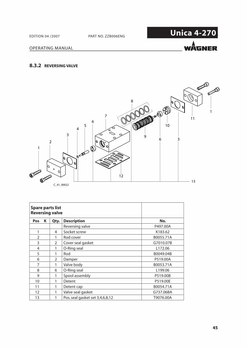
8.3.2 REVERSING VALVE
Spare parts list Reversing valve
Pos K Qty. Description No.Reversing valve P497.00A
1 4 Socket screw K183.622 1 Rod cover B0055.71A3 2 Cover seal gasket G7010.07B4 1 O-Ring seal L172.065 1 Rod B0049.04B6 2 Damper P519.00A7 1 Valve body B0053.71A8 6 O-Ring seal L199.069 1 Spool assembly P519.00B
10 1 Detent P519.00E11 1 Detent cap B0054.71A12 1 Valve seal gasket G737.06BA13 1 Pos. seal gasket set 3,4,6,8,12 T9076.00A
46
Unica 4-270.
1
2
4
3
186
78
9 (**)
12
14
11
13
10
5
5
15
16
10
17
1011
12
13
14
9 (*) 87
618
5
2 1
43
5
10
16
(**)(*)
55 Nm; 40.7 lbft
55 Nm; 40.7 lbft
55 Nm; 40.7 lbft
55 Nm; 40.7 lbft
OPERATING MANUAL
EDITION 04 /2007 PART NO. ZZB006ENG
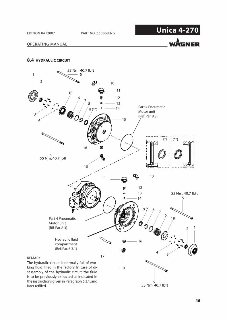
8.4 HYDRAULIC CIRCUIT
Hydraulic fl uid compartment(Ref. Par. 6.3.1)
REMARK:The hydraulic circuit is normally full of wor-king fl uid fi lled in the factory. In case of di-sassembly of the hydraulic circuit, the fl uid is to be previously extracted as indicated in the instructions given in Paragraph 6.3.1, and later refi lled.
Part 4 Pneumatic Motor unit(Rif. Par. 8.3)
Part 4 Pneumatic Motor unit(Ref. Par. 8.3)
47
Unica 4-270.
OPERATING MANUAL
EDITION 04 /2007 PART NO. ZZB006ENG
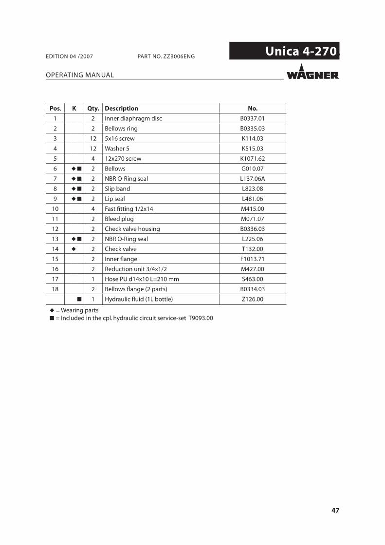
Pos. K Qty. Description No.
1 2 Inner diaphragm disc B0337.01
2 2 Bellows ring B0335.03
3 12 5x16 screw K114.03
4 12 Washer 5 K515.03
5 4 12x270 screw K1071.62
6 ◆ ■ 2 Bellows G010.07
7 ◆ ■ 2 NBR O-Ring seal L137.06A
8 ◆ ■ 2 Slip band L823.08
9 ◆ ■ 2 Lip seal L481.06
10 4 Fast fi tting 1/2x14 M415.00
11 2 Bleed plug M071.07
12 2 Check valve housing B0336.03
13 ◆ ■ 2 NBR O-Ring seal L225.06
14 ◆ 2 Check valve T132.00
15 2 Inner fl ange F1013.71
16 2 Reduction unit 3/4x1/2 M427.00
17 1 Hose PU d14x10 L=210 mm S463.00
18 2 Bellows fl ange (2 parts) B0334.03
■ 1 Hydraulic fl uid (1L bottle) Z126.00
◆ = Wearing parts■ = Included in the cpl. hydraulic circuit service-set T9093.00
48
Unica 4-270.
9
10 2
3
45 N/m; 33 lbft
16
125 N/m; 18.5 lbft
3
125 N/m; 18.5 lbft
22
9
45 N/m; 33 lbft
16
11
1213
1514
4
6
8
5
7
4
876
5
60 N/m; 44 lbft17
21 (*)201918
21 (*)
20
19 18
4
6
8
5
7
1011
5
7
6
84
23
23
2425
26
1760 N/m; 44 lbft
OPERATING MANUAL
EDITION 04 /2007 PART NO. ZZB006ENG
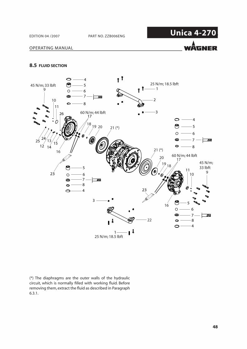
8.5 FLUID SECTION
(*) The diaphragms are the outer walls of the hydraulic circuit, which is normally fi lled with working fl uid. Before removing them, extract the fl uid as described in Paragraph 6.3.1.
49
Unica 4-270.
OPERATING MANUAL
EDITION 04 /2007 PART NO. ZZB006ENG
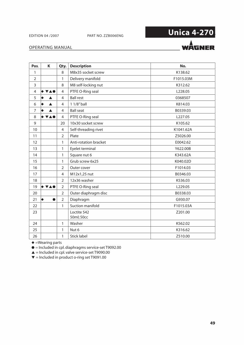
Pos. K Qty. Description No.
1 8 M8x35 socket screw K138.62
2 1 Delivery manifold F1015.03M
3 8 M8 self-locking nut K312.62
4 ◆ ▼▲● 4 PTFE O-Ring seal L228.05
5 ◆ ▲ 4 Ball rest 0368507
6 ◆ ▲ 4 1 1/8” ball K814.03
7 ◆ ▲ 4 Ball seat B0339.03
8 ◆ ▼▲● 4 PTFE O-Ring seal L227.05
9 20 10x30 socket screw K105.62
10 4 Self-threading rivet K1041.62A
11 2 Plate Z5026.00
12 1 Anti-rotation bracket E0042.62
13 1 Eyelet terminal Y622.00B
14 1 Square nut 6 K343.62A
15 1 Grub screw 6x25 K040.02D
16 2 Outer cover F1014.03
17 4 M12x1,25 nut B0346.03
18 2 12x36 washer K536.03
19 ◆ ▼▲● 2 PTFE O-Ring seal L229.05
20 2 Outer diaphragm disc B0338.03
21 ◆ ● 2 Diaphragm G930.07
22 1 Suction manifold F1015.03A
23 Loctite 54250ml; 50cc
Z201.00
24 1 Washer K562.02
25 1 Nut 6 K316.62
26 1 Stick label Z510.00
◆ =Wearing parts● = Included in cpl. diaphragms service-set T9092.00▲ = Included in cpl. valve service-set T9090.00▼ = Included in product o-ring set T9091.00
50
Unica 4-270.
OPERATING MANUAL
EDITION 04 /2007 PART NO. ZZB006ENG

ZZB006ENG