high performance tier implementation · pdf filehigh performance tier implementation...
TRANSCRIPT

High Performance Tier Implementation Guideline
A Dell Technical White Paper
PowerVault™ MD3200 and MD3200i Storage Arrays

MD32xx & MD32xxi High Performance Tier: Best Practices Implementation
Page ii
THIS WHITE PAPER IS FOR INFORMATIONAL PURPOSES ONLY, AND MAY CONTAIN TYPOGRAPHICAL ERRORS AND TECHNICAL INACCURACIES. THE CONTENT IS PROVIDED AS IS, WITHOUT EXPRESS OR IMPLIED WARRANTIES OF ANY KIND.
© 2010 Dell Inc. All rights reserved. Reproduction of this material in any manner whatsoever without the express written permission of Dell Inc. is strictly forbidden. For more information, contact Dell.
Dell, the DELL logo, and the DELL badge, PowerConnect, and PowerVault are trademarks of Dell Inc. Other trademarks and trade names may be used in this document to refer to either the entities claiming the marks and names or their products. Dell Inc. disclaims any proprietary interest in trademarks and trade names other than its own.
June 2010
MD32xx & MD32xxi High Performance Tier: Best Practices Implementation
Page 1
Contents What is High Performance Tier? ...................................................................................... 2
What are the Performance Advantages of High Performance Tier? ........................................... 2
When Should High Performance Tier be used? .................................................................... 2
Introduction ........................................................................................................... 2
Number of Disk Drives ............................................................................................... 3
Workload Dependencies ............................................................................................ 3
RAID Types ............................................................................................................ 4
How is High Performance Tier Enabled and Disabled? ........................................................... 4
What are the Best Tuning Practices for High Performance Tier? .............................................. 4
Performance Analysis .................................................................................................. 6
Introduction ........................................................................................................... 6
System Configuration for iSCSI .................................................................................... 6
System Topology for iSCSI .......................................................................................... 6
System Configuration for SAS ...................................................................................... 7
System Topology for SAS ............................................................................................ 7
Back-End SAS Cabling Diagram .................................................................................... 8
iSCSI Performance Data Base vs. High Performance Tier ..................................................... 8
SAS Performance Data Base vs. High Performance Tier..................................................... 10
MD32xx & MD32xxi High Performance Tier: Best Practices Implementation
Page 2
What is High Performance Tier?
High Performance Tier (also known as High Performance Tier Mode) is an optional upgrade that can increase the performance of MD3200 and MD3220 series arrays that have a high drive count, Solid state drives (SSDs) or high data transfer workloads. This implementation is based on an enhanced firmware algorithm and does not require any new hardware dependencies. Several factors will determine the potential performance increase, including the array configuration, host, operating system, HBA, number and types of drives, and application workload.
What are the Performance Advantages of High Performance Tier?
High Performance Tier uses the enhanced firmware with the existing hardware to extend the performance of the storage array. Enabling High Performance Tier improves the performance of the array in both data transfer rate (bandwidth) and I/O transactions per second (IOPS). The main advantages are increased bandwidth for sequential and random workloads, and increased IOPS for random workloads. For data transfer intensive workloads, both read and write bandwidth can be doubled, while for random access workload patterns, an increase of one-third has been measured.
When Should High Performance Tier be used?
Introduction
High Performance Tier will be most beneficial when the workload intensity exceeds the controller’s performance capability in base mode and the system configuration will support additional performance. Two primary aspects of workload are transactions per second, often represented as IOPS, and data rate or bandwidth. These factors will combine in varying ratios depending on the workload mix.
To present the MD32xx/MD32xxi with a workload that exceeds the base product limits, several factors must be realized. For high bandwidth applications, the following factors are essential for optimizing data transfer capability:
• Enough host links to provide the data rates to reach the controller’s limit. If there is a single host link to a controller it may not provide enough bandwidth to exceed the base performance capability.
• The workload from the host servers is adequate to exceed the controller’s base performance specifications. This is usually accomplished with large transfer sizes and enough outstanding IOs to keep the link saturated.
• Sufficient disk groups properly configured to support the data rates required. • A rough guideline for bandwidth requirements would be enough host interface capability to sustain
at least 1000 MB/s of data transfer rate per controller.
IO completions per second, or IOPS, will be maximized for smaller transfer sizes. If the controller CPU is not fully utilized, maximum IOPS will not be achieved. If the workload is not sufficient to exceed base product performance specifications or target configuration is not optimized for performance, then
MD32xx & MD32xxi High Performance Tier: Best Practices Implementation
Page 3
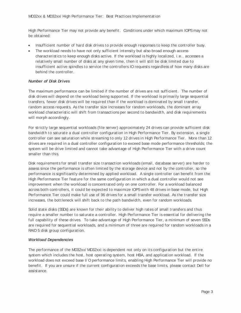
High Performance Tier may not provide any benefit. Conditions under which maximum IOPS may not be obtained:
• Insufficient number of hard disk drives to provide enough responses to keep the controller busy. • The workload needs to have not only sufficient intensity but also broad enough access
characteristics to keep enough disks active. If the workload is highly localized, i.e., accesses a relatively small number of disks at any given time, then it will still be disk limited due to insufficient active spindles to service the controllers IO requests regardless of how many disks are behind the controller.
Number of Disk Drives
The maximum performance can be limited if the number of drives are not sufficient. The number of disk drives will depend on the workload being supported. If the workload is primarily large sequential transfers, fewer disk drives will be required than if the workload is dominated by small transfer, random access requests. As the transfer size increases for random workloads, the dominant array workload characteristic will shift from transactions per second to bandwidth, and disk requirements will morph accordingly.
For strictly large sequential workloads (file server) approximately 24 drives can provide sufficient disk bandwidth to saturate a dual controller configuration in High Performance Tier. By extension, a single controller can see saturation while streaming to only 12 drives in High Performance Tier. More than 12 drives are required in a dual controller configuration to exceed base mode performance thresholds; the system will be drive limited and cannot take advantage of High Performance Tier with a drive count smaller than this.
Disk requirements for small transfer size transaction workloads (email, database server) are harder to assess since the performance is often limited by the storage device and not by the controller, so the performance is significantly determined by applied workload. A single controller can benefit from the High Performance Tier feature for the same configuration in which a dual controller would not see improvement when the workload is concentrated only on one controller. For a workload balanced across both controllers, it could be expected to maximize IOPS with 48 drives in base mode, but High Performance Tier could make full use of 96 drives for a small transfer workload. As the transfer size increases, the bottleneck will shift back to the path bandwidth, even for random workloads.
Solid state disks (SSDs) are known for their ability to deliver high rates of small transfers and thus require a smaller number to saturate a controller. High Performance Tier is essential for delivering the full capability of these drives. To take advantage of High Performance Tier, a minimum of seven SSDs are required for sequential workloads, and a minimum of three are required for random workloads in a RAID 5 disk group configuration.
Workload Dependencies
The performance of the MD32xx/MD32xxi is dependent not only on its configuration but the entire system which includes the host, host operating system, host HBA, and application workload. If the workload does not exceed base I/O performance limits, enabling High Performance Tier will provide no benefit. If you are unsure if the current configuration exceeds the base limits, please contact Dell for assistance.

MD32xx & MD32xxi High Performance Tier: Best Practices Implementation
Page 4
RAID Types
High Performance Tier should provide an improvement in performance for all RAID types supported by the MD32xx/MD32xxi. Characteristic performance for individual RAID types will not change – for example, RAID 0 will in general, have better WRITE performance than RAID 5; these types of inter-RAID type relationships will remain the same.
How is High Performance Tier Enabled and Disabled?
High Performance Tier is enabled using the MDSM management application by applying a Premium Feature key purchased from Dell. In order to have this key generated, you must provide the Feature Enable Identifier referenced in MDSM.
1. Obtain the Feature Enable Identifier by opening the Premium Features and Feature Pack Information window by selecting Premium Features from the Storage Array main menu item.
2. Provide your unique identifier to a Dell representative who will generate a key based on this
information. 3. Enable High Performance Tier by highlighting High Performance Tier entry in Premium Features
listing and select Enable to select High Performance Tier key provided by Dell. Once the key has been selected all MD32xx/MD32xxi controllers will perform a reboot automatically, PLEASE PLAN ACCORDINGLY.
4. Verify High Performance Tier entry in Premium Features listing changes to Enabled.
What are the Best Tuning Practices for High Performance Tier?
Proper array and server tuning is essential for realizing the advantages of High Performance Tier. If a storage system is not optimally tuned the benefits from High Performance Tier may not be fully realized. For sequential workloads, a controller cache block size of 32KB should be used (the default

MD32xx & MD32xxi High Performance Tier: Best Practices Implementation
Page 5
setting is 4KB). The cache setting may be changed by selecting Change -> Cache Settings from the Storage Array main menu item.
For random workloads, a controller cache block size of 16KB should be used, and cache pre-fetch should be disabled for each virtual disk. Virtual disk cache settings may be change by selecting Change -> Cache Settings from the Virtual Disk main menu item.
If the workloads are a mix of sequential and random IO, we initially recommend using the 16KB cache block with cache pre-fetch disabled, but encourage the system administrator to adjust cache block size as necessary to achieve the optimal results. Cache block size may be changed ‘on the fly’ without requiring a controller reset, and live system tuning may be required in some cases.
MD32xx & MD32xxi High Performance Tier: Best Practices Implementation
Page 6
Performance Analysis
Introduction
The purpose of this data and these tests are to show how an MD32xx/MD32xxi configuration using default settings (cache block size = 4KB, read cache enabled, write cache enabled, cache mirroring enabled, cache pre-fetch enabled, and segment size = 128KB) may benefit from High Performance Tier. It was not the intent of this report to show maximum performance characteristics of the MD32xx/MD32xxi.
System Configuration for iSCSI
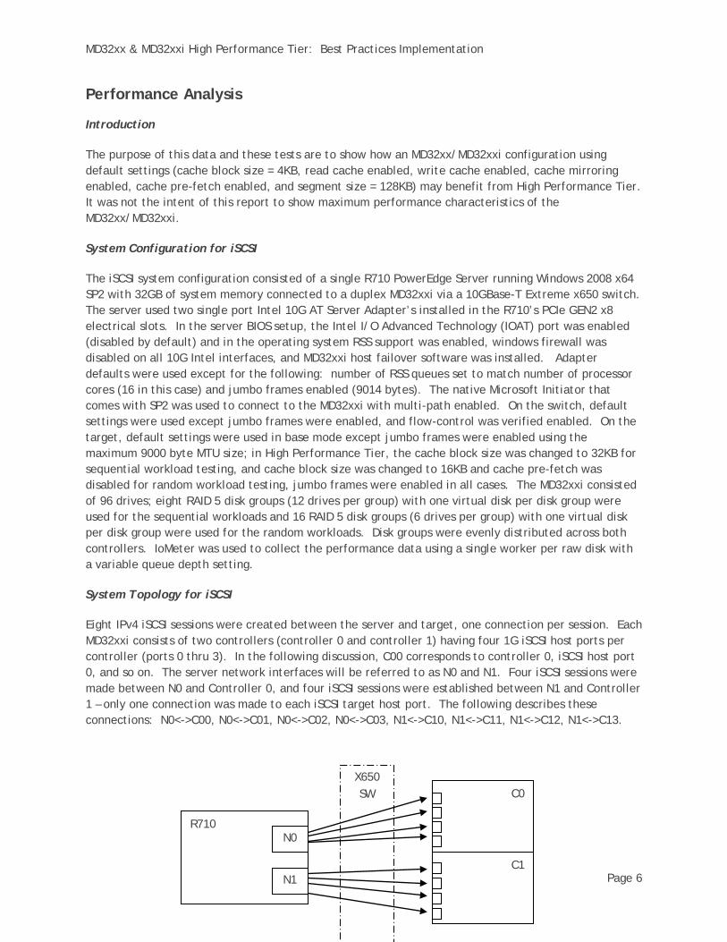
The iSCSI system configuration consisted of a single R710 PowerEdge Server running Windows 2008 x64 SP2 with 32GB of system memory connected to a duplex MD32xxi via a 10GBase-T Extreme x650 switch. The server used two single port Intel 10G AT Server Adapter’s installed in the R710’s PCIe GEN2 x8 electrical slots. In the server BIOS setup, the Intel I/O Advanced Technology (IOAT) port was enabled (disabled by default) and in the operating system RSS support was enabled, windows firewall was disabled on all 10G Intel interfaces, and MD32xxi host failover software was installed. Adapter defaults were used except for the following: number of RSS queues set to match number of processor cores (16 in this case) and jumbo frames enabled (9014 bytes). The native Microsoft Initiator that comes with SP2 was used to connect to the MD32xxi with multi-path enabled. On the switch, default settings were used except jumbo frames were enabled, and flow-control was verified enabled. On the target, default settings were used in base mode except jumbo frames were enabled using the maximum 9000 byte MTU size; in High Performance Tier, the cache block size was changed to 32KB for sequential workload testing, and cache block size was changed to 16KB and cache pre-fetch was disabled for random workload testing, jumbo frames were enabled in all cases. The MD32xxi consisted of 96 drives; eight RAID 5 disk groups (12 drives per group) with one virtual disk per disk group were used for the sequential workloads and 16 RAID 5 disk groups (6 drives per group) with one virtual disk per disk group were used for the random workloads. Disk groups were evenly distributed across both controllers. IoMeter was used to collect the performance data using a single worker per raw disk with a variable queue depth setting.
System Topology for iSCSI
Eight IPv4 iSCSI sessions were created between the server and target, one connection per session. Each MD32xxi consists of two controllers (controller 0 and controller 1) having four 1G iSCSI host ports per controller (ports 0 thru 3). In the following discussion, C00 corresponds to controller 0, iSCSI host port 0, and so on. The server network interfaces will be referred to as N0 and N1. Four iSCSI sessions were made between N0 and Controller 0, and four iSCSI sessions were established between N1 and Controller 1 – only one connection was made to each iSCSI target host port. The following describes these connections: N0<->C00, N0<->C01, N0<->C02, N0<->C03, N1<->C10, N1<->C11, N1<->C12, N1<->C13.
X650 SW
R710
C0
C1
N0
N1

MD32xx & MD32xxi High Performance Tier: Best Practices Implementation
Page 7
The arrows represent iSCSI sessions, not physical connections. The server has two physical 10G interfaces, and the MD32xxi has eight physical 1G interfaces (four per controller).
System Configuration for SAS
The 6G SAS system configuration consisted of a single R710 PowerEdge Server running Windows 2008 x64 SP2 with 32GB of system memory connected to a duplex MD32xx using two Dell 6G SAS HBA’s with MD32xx host failover software installed. The HBA’s were installed in the R710’s PCIe GEN2 x8 electrical slots and default adapter settings used. On the target, default settings were used in base mode; in High Performance Tier, the cache block size was changed to 32KB for sequential workload testing, and cache block size was changed to 16KB and cache pre-fetch was disabled for random workload testing. The MD32xx consisted of 96 drives; four RAID 5 disk groups (24 drives per group) with one virtual disk per disk group were used for the sequential workloads and 16 RAID 5 disk groups (6 drives per group) with one virtual disk per disk group were used for the random workloads. Disk groups were evenly distributed across both controllers. IoMeter was used to collect the performance data using a single worker per raw disk with a variable queue depth setting.
System Topology for SAS
Four connections were made between the server and MD32xx. Each MD32xx consists of two controllers (controller 0 and controller 1) having four 6G SAS host ports per controller (ports 0 thru 3). In the following discussion, C00 corresponds to controller 0 SAS host port 0, and so on. The server HBA interfaces will be referred to as S0, S1, S2 and S3 – each HBA has two SAS ports, S0 and S1 reside on one HBA, and S2 and S3 reside on the other HBA. Two SAS connections were made between S0, S1 and Controller 0, and two SAS connections were established between S2, S3 and Controller 1. The following describes these connections: S0<->C00, S1<->C02, S2<->C10, S3<->C12.
R710 S0
S1
C0
C1 S2
S3

MD32xx & MD32xxi High Performance Tier: Best Practices Implementation
Page 8
Back-End SAS Cabling Diagram
An asymmetric cabling method was used on both the SAS and iSCSI systems to interconnect controller and drive shelves. There is no evidence to show asymmetric vs. symmetric cabling improves performance, but it’s added here for consistency and best cabling practices. For asymmetric cabling, controller 0 (TOP (0)) connects to the top drive shelf controller (TOP (1)), and controller 1 (BOTTOM (0)) connects to the bottom drive shelf controller (BOTTOM (N)) – the drive shelves are then subsequently daisy chained as normal.
TOP(0) BOTTOM(0)
TOP(1) BOTTOM(1)
TOP(2) BOTTOM(2)
TOP(N) BOTTOM(N)
The “N” refers to the last shelf in the configuration.
iSCSI Performance Data Base vs. High Performance Tier
The following charts show Base vs. High Performance Tier performance for sequential READ (100/0 R/W), sequential WRITE (0/100 R/W) in MiB/s (1MiB = 1024*1024B), random READ (100/0 R/W) IOPS, and random WRITE (0/100 R/W) IOPS for transfer sizes ranging from 512B to 4MB.
0
200
400
600
800
1000
1200SEQUENTIAL READ (MiB/s)
Base
TurboHPT

MD32xx & MD32xxi High Performance Tier: Best Practices Implementation
Page 9
0
200
400
600
800
1000
1200SEQUENTIAL WRITE (MiB/s)
Base
Turbo
0
5000
10000
15000
20000
25000
30000
35000
40000RANDOM READ IOPS
Base
TurboHPT
HPT
MD32xx & MD32xxi High Performance Tier: Best Practices Implementation
Page 10
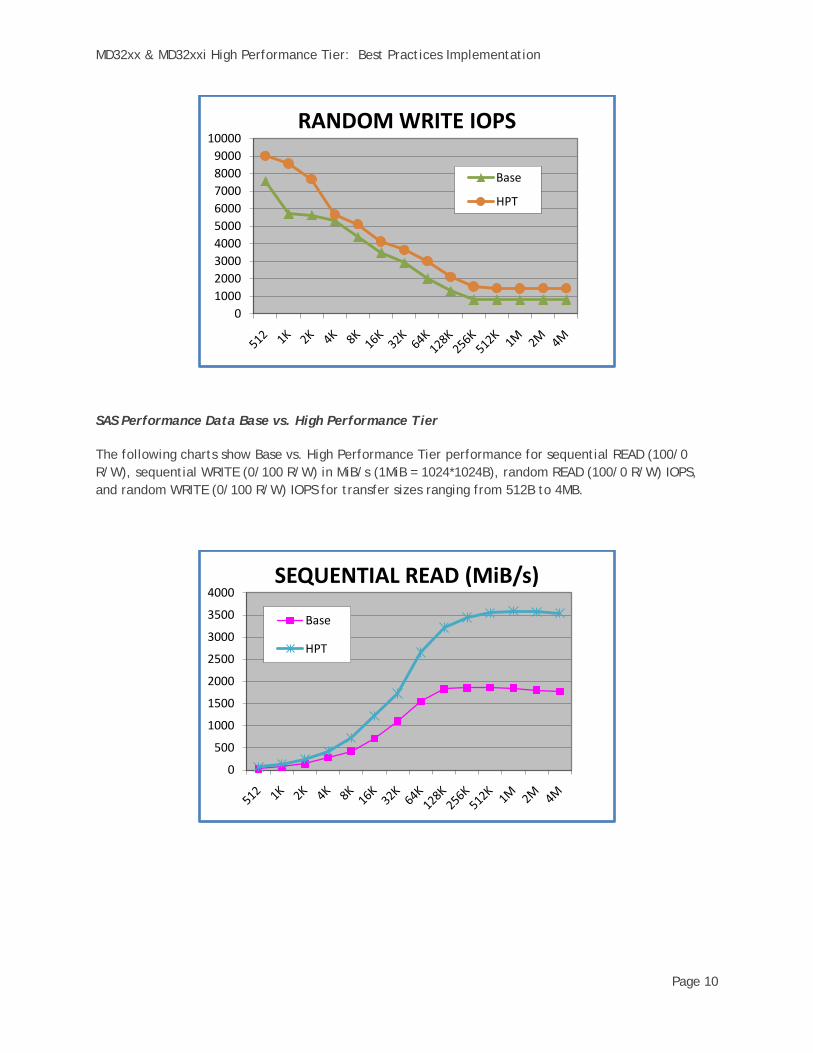
SAS Performance Data Base vs. High Performance Tier
The following charts show Base vs. High Performance Tier performance for sequential READ (100/0 R/W), sequential WRITE (0/100 R/W) in MiB/s (1MiB = 1024*1024B), random READ (100/0 R/W) IOPS, and random WRITE (0/100 R/W) IOPS for transfer sizes ranging from 512B to 4MB.
0100020003000400050006000700080009000
10000RANDOM WRITE IOPS
Base
Turbo
0
500
1000
1500
2000
2500
3000
3500
4000SEQUENTIAL READ (MiB/s)
Base
TurboHPT
HPT

MD32xx & MD32xxi High Performance Tier: Best Practices Implementation
Page 11
0
200
400
600
800
1000
1200
1400
1600SEQUENTIAL WRITE (MiB/s)
Base
Turbo
05000
1000015000200002500030000350004000045000
RANDOM READ IOPS
Base
TurboHPT
HPT