high performance micro actuators for … xin.pdf · actuation function. ... appendix d...
TRANSCRIPT

HIGH PERFORMANCE MICRO ACTUATORS FOR TACTILE DISPLAYS
A Dissertation Presented
By
Xin Xie
to
The Department of Electrical and Computer Engineering
in partial fulfillment of the requirements for the degree of
Doctor of Philosophy
in the field of
Electrical Engineering
Northeastern University Boston, Massachusetts
May 2017

ProQuest Number:
All rights reserved
INFORMATION TO ALL USERSThe quality of this reproduction is dependent upon the quality of the copy submitted.
In the unlikely event that the author did not send a complete manuscriptand there are missing pages, these will be noted. Also, if material had to be removed,
a note will indicate the deletion.
ProQuest
Published by ProQuest LLC ( ). Copyright of the Dissertation is held by the Author.
All rights reserved.This work is protected against unauthorized copying under Title 17, United States Code
Microform Edition © ProQuest LLC.
ProQuest LLC.789 East Eisenhower Parkway
P.O. Box 1346Ann Arbor, MI 48106 - 1346
10273384
10273384
2017

ii
ABSTRACT
Providing information to those who are blind or have low vision is critical for enhancing
mobility, situational awareness, education, and more. Tactile information delivery can be
effective, rapid, and private. Examples include refreshable Braille and text based tactile
displays, both of which convey text to the user through either quasistatic or vibratory
motion of piezoelectric bending beam actuators. However, not all information can be
conveyed easily in text format. Graphical information that sighted people would perceive
visually (e.g. scientific diagrams) can best be expressed to those with visual impairment
through tactile graphics. Existing technologies of tactile actuators lack the necessary
combination of compact size, large displacement and force, portability and cost
effectiveness.
In this work, a new type of tactile actuator is designed, modeled, implemented,
and characterized. The technologies needed to create these actuators are created as well.
In these actuators, the small, in-plane motions from an extensional actuator are converted
and amplified by a scissor mechanism into larger, out-of-plane motions that are suitable
for tactile sensing by human finger pads. These actuators offer the possibility of
providing large displacement and high force from a limited device area that is
comparable to the resolution of human finger pads. The design, fabrication and
characterization of several technology generations of MEMS-enabled, vibrational tactile
actuators are presented. In the first generation, flexural hinges created by additive

iii
manufacturing and in photodefinable epoxy are used to implement the jointed scissor
architecture. In the second generation, a down-scaled architecture is created by
implementing flexural hinges in a more compact geometry and a laminated architecture.
In the third and fourth generations of the device design, the jointed architecture is
implemented using two-part, concentric hinges that undergo free rotation within a given
rotational range. These technologies enable the creation of tactile actuators down to the
size scale of 2 mm2 area. The resulting tactile actuators deliver force per-unit-area of
greater than 2.5 mN/mm2 and displacement per-unit-area of greater than 1.5 µm/mm2.
Human sensing perception testing was also conducted, demonstrating successful tactile
actuation function. These actuators have potential in applications like virtual reality
sensory feedback, private communications and microrobotics.

iv
ACKNOWLEDGMENTS
I would like to express my foremost appreciation to my advisor, Prof. Carol Livermore
for offering me a research home in her Micropower and Nanoengineering Lab at
Northeastern University. I am really grateful for her guidance, advising, support and love
during my graduate career. Without her valuable knowledge, experience, suggestions and
assistance, this thesis can never happen.
I would like to thank my Ph.D. committee members, Prof. Matteo Rinaldi and Prof.
Yongmin Liu for their advising, suggestions and contributions to my research. They are
always been very helpful by generously sharing their knowledge and encouragement.
Many thanks to Prof. Seth Teller and Dr. Luis Velásquez-García at MIT for initiating this
research project with Prof. Carol Livermore, and for their contribution to the design and
fabrication suggestions.
It was my great pleasure working with Yuri Zaitsev and Battushig Myanganbayar on this
research project. I would also like to say thank you to my labmates Sanwei Liu, Chenye
Yang, Tian Liu, Majid Bigdeli Karimi, Chase Kelly, William Zhu, Philipp Mehner and
all summer students and teachers, it’s been a glad experience working with these amazing
people on various interesting projects.
Last but not least, I am indebted to my family. To my parents, Yongquan Xie and Hongju
Ren, thank you for always be there with me and support me. To my lovely wife Chunman,

v
gratefully thank you for taking great care of me and our little man Eric, and for your
always support of my dream in contributing my passion to the world of science and
engineering.

vi
TABLE OF CONTENTS
1. INTRODUCTION …………………………………………………………………….1
1.1 Motivations ………………………………………………………………………6
1.2 Research Contributions ………………………………………………………….7
1.3 Thesis Roadmap …………………………………………………………………..8
2. TACTILE PERCEPTION AND TACTILE INFORMATION DELIVERY ……….10
2.1 Mechanoreceptors ……………………………………………………………….10
2.2 Stimulation Methods and Actuation Technologies ……………………………..14
2.2.1 Thermal …………………………………………………………………..15
2.2.2 Electrotactile ……………………………………………………………..16
2.2.3 Mechanical ……………………………………………………………….16
2.2.3.1 Static Indentation ………………………………………………16
2.2.3.2 Vibration ……………………………………………………….17
2.2.3.3 Surface Acoustic Waves ………………………………………..18
2.2.3.4 Electrorheological and Magnetorheological Fluids …………..18
2.3 Vibrotactile Actuators for Tactile Feedback …………………………………….18
2.3.1 Rotary Electromagnet Actuators …………………………………………19
2.3.2 Linear Electromagnetic Actuators ……………………………………….19
2.3.3 Electroactive Polymer ……………………………………………………20
2.3.4 Shape Memory Alloy ……………………………………………………..20
2.3.5 Piezoelectric Actuators …………………………………………………..21
2.3.5.1 Piezoelectric Bending Beam Actuators ………………………..23

vii
2.3.5.2 Piezoelectric Extensional Beam Actuators ……………………..23
2.3.6 Pneumatic Actuation …………………………………………………….25
2.4 Conclusion ………………………………………………………………………26
3. DESIGN AND MODELING ………………………………………………………..27
3.1 Device Specifications ……………………………………………………………27
3.2 Ideal Tactile Element Performance ……………………………………………...28
3.3 MEMS-Scale and Milli-Scale Systems Illustration …………………………….36
4. TACTILE ACTUATORS WITH MONOLITHIC FLEXURAL HINGES ………..41
4.1 Design …………………………………………………………………………..41
4.2 Individual Actuator Fabrication …………………………………………………45
4.3 Element Connection and Array Fabrication …………………………………….49
4.4 Testing Protocol …………………………………………………………………52
4.5 Quantitative Measurements ……………………………………………………..57
4.6 Qualitative Testing ………………………………………………………………61
4.7 Chapter Summary ……………………………………………………………….65
5. TACTILE ACTUATORS WITH LAMINATED FLEXURAL HINGES …………67
5.1 Design …………………………………………………………………………..69
5.2 Fabrication ………………………………………………………………………71
5.3 Experiments and Results ………………………………………………………..79
5.4 Chapter Summary ……………………………………………………………….83
6. TACTILE ACTUATORS WITH PIVOT HINGES ………………………………...84
6.1 Design and Fabrication …………………………………………………………84
6.2 Experiments and Results ……………………………………………………….93
6.3 Chapter Summary ……………………………………………………………….97
7. TACTILE ACTUATORS WITH BARREL HINGES ……………………………..98
7.1 Design …………………………………………………………………………..99
7.2 Fabrication …………………………………………………………………….100

viii
7.3 Experiments and Results ………………………………………………………112
7.4 Chapter Summary ………………………………………………………………114
8. CONCLUSION AND FUTURE WORK …………………………………………116
8.1 Summary of Contributions …………………………………………………….116
8.2 Suggested Future Work ………………………………………………………..117
8.2.1 Minimizing Vibrational Damping ……………………………………..117
8.2.2 Self-aligned Assembly for the Laminated Scissors in Chapter 5 ………118
8.2.3 Investigation of How the Shape and Area of Sensing Pin Affect the Finger Sensory ……………………………………………………………………….119
8.2.4 A New Design Aiming to Double Displacement Per Unit Area ……….119
8.2.5 A 10 × 10 Tactile Display Array ………………………………………121
8.3 Conclusion …………………………………………………………………….121
9. REFERENCES …………………………………………………………………..123
10. Appendix A Microfabrication Process for Chapter 4 ……………………………132
11. Appendix B Microfabrication Process for Chapter 5 ……………………………134
12. Appendix C Microfabrication Process for Chapter 6 ……………………………136
13. Appendix D Microfabrication Process for Chapter 7 ……………………………142
14. Appendix E Useful Notes in Microfabrication …………………………………..148
15. Appendix F Northeastern University HSRP Approval Form …………………..149

1
Chapter 1
INTRODUCTION
We sense the world through different information perception channels; examples
include sight, smell, hearing, taste, and touch (Serres, 2008). Tactile (touch-based)
sensing, which is among the five basic senses when born, plays an important role in
getting information like object properties, motion, and force. Although touch plays a
critical role in babies’ and children’s early learning (Stack, 1994), information is more
commonly delivered to older children and adults by visual means, such as written text,
maps, graphs, pictures, and so forth. However, for those with low vision or who are
visually impaired, perceiving visible information is not an effective option. Audio
information delivery is one option for conveying information that a sighted person would
perceive visually. Audio delivery is more commonly used for some types of information
(e.g. text-to-speech) than for others (e.g. representation of a graph), and it can also limit a
blind person’s use of their ears for other purposes. Tactile information delivery is a
second option for conveying information that a sighted person would perceive visually.
Tactile delivery may be used to convey text (e.g. via Braille) and graphics (e.g. via
embossed patterns in paper), making the tactile sense a critical channel for enhancing
mobility, situational awareness, education and more. Tactile information delivery can be
effective, rapid, and private. Thus tactile display technology is in demand to deliver a
human machine interface that allows rich information communication. The importance of
tactile communication is apparent not only in our daily lives (especially in assistive
technologies), but also in greater demand for tactile sensors and actuators in applications
like virtual reality, human centered robotics, and private communications.

2
There are effective ways to convey text information. Braille is a tactile coding
system developed by Louis Braille in 1824 (Jiménez, 2009). This system is the most
widely used tactile language among people who are blind or visually impaired around the
world. Each Braille unit cell is a rectangular block that consists of a 2 x 3 or 2 x 4 array
of dots. The dots are encoded to either an out-of-plane bump or a plane dot, and the
pattern of dots represents different characters and meanings. This is a useful system for
exchanging static information, but traditional Braille must be preprinted on paper or
another carrier material, and it contains fixed information. The fact that printed Braille is
not able to show changing information in real time limits its use for more complicated
tasks like interaction, communication, and changing graphical demonstration. What is
really needed is a high resolution system that is able to deliver rich and changing
information to describe the time varying environment instantly.
There are also technologies to deliver changing text information. Examples
include refreshable Braille (Nakajima, 1991) and the Optacon (Bliss, 1970), both of
which convey text to the user through either quasi-static or vibratory motion of
piezoelectric bending beam actuators that are several centimeters in length. Refreshable
Braille displays in particular typically convey text information to a line of Braille
elements for people who are blind to read and learn. The dots of each element switch
between “bump” and “plane” positions when the device is refreshed; their motion is
triggered by actuators underneath the touch panel. Refreshable Braille actuators are
quasi-static. They are not able to show real-time information. Humans tend to detect
changes and moving objects more easily than they detect static patterns; thus a large
amplitude (an out-of-plane height) of 0.48 mm (U.S. Access Board, 2004) for a

3
conventional Braille display is needed in order to effectively convey the bumps. In fact,
refreshable Braille actuators typically have to be on the scale of centimeters in their
longest dimension, so that the individual actuators often must be stacked one over the
other with their long dimensions extending into the space off to either side or below the
actuators to fit them in the limited area as shown in figure 1.1. The most commonly used
actuator in commercial available refreshable Braille is the piezoelectric bending actuator;
its detailed working principle will be discussed in the next chapter. Piezoelectric material
is expensive and the electrical control unit for each piezoelectric bending actuator can be
complicated and bulky. The refreshable Braille display device usually utilizes a lot of the
piezoelectric material, which limits the whole device’s cost effectiveness and
compactness.
Figure 1.1: A refreshable Braille display unit by Metec.
However, not all information can be conveyed easily in text format. Graphical
information that sighted people would perceive visually (e.g. scientific diagrams,
mathematical plots, or icon-based signage) can best be expressed to those with visual
impairment through tactile graphics. The most commonly-used technology for conveying

4
tactile graphics is embossing of images on paper. Similar to Braille printing methods, the
embossed patterns are realized on substrates like paper (e.g. thermoform or microcapsule
paper), plastic, or metal by creating 3D shapes (Rowell, 2003). These methods are
effective, but each image is static and cannot convey information that changes in real
time. A refreshable 2D graphical interface would be preferred; however, it is challenging
to create actuators that are compact enough to be arrayed into an arbitrarily large number
of rows and columns. In addition, the actuators would need to be robust, easy to sense,
and rapidly switchable to convey information in real time. Two-dimensional graphical
interface arrays have been created, such as the HyperBraille® created by Metec Ingenieur
AG. In these systems, the actuators are engineered so that their long dimensions are
oriented perpendicular to the plane and protrude beneath the sensing surface. This
approach makes it possible to create an arbitrarily large 2D array with large enough
actuations for quasi-static sensing, but its large actuators do not address the challenges of
cost and bulk.
One possible solution to the challenges of cost and bulk is to use time-varying
stimuli rather than quasi-static stimuli. Because humans are more sensitive to changing
stimuli than to static stimuli (see chapter 2 for details), smaller actuations are required to
convey changing stimuli than are required to convey quasi-static stimuli. Lower sensing
thresholds mean smaller displacement and smaller force are needed from the tactile
actuators, enabling potentially smaller actuator sizes. The spatial resolution of human
finger pads is about 1 mm2 (Boven, 1994) This suggests that actuator sizes down to about
1 mm2 per element can improve the user experience, but that actuator sizes smaller than 1

5
mm2 will not lead to better user experience because human normally cannot distinguish
two stimuli within 1 mm.
Microelectromechanical systems (MEMS) actuators are well matched to this size
level. However, MEMS actuators’ typical force and displacement ranges are not well-
matched to purely MEMS actuators. The maximum forces of MEMS actuators are up to
10-3 N and their maximum displacements are up to 10-3 m (Bell, 2005), but these
extremes are not accomplished simultaneously in a given actuator. As a result, MEMS
actuator performance is not typically large enough to create effective tactile sensations on
the order of 10-2 N and 10-2 m as required for vibratory actuation (Xie, 2014). In addition,
the robustness for MEMS actuators is limited as compared with macro actuators, so that
they risk damage under the mechanical load of touch. MEMS actuators also typically
have significant design and fabrication complexity.
The main challenge in creating a small-sized actuator for high resolution tactile
displays is that conventional macro actuators are large in size, making high resolution
hard to implement, whereas MEMS actuators are small, making adequate force and
displacement for human sensing difficult to attain. This thesis demonstrates how a new
type of actuator can bridge the gap between macroscale forces and microscale
compactness to create effective tactile stimuli at the MEMS size scale. The actuator
converts forceful but small amplitude in-plane actuations from a bulk piezoelectric
extensional actuator into less forceful, larger-amplitude out-of-plane actuations via a
scissor mechanism as shown in figure 1.2; details of the actuator design and
implantations will be discussed in the following chapters. These actuators leverage the
properties of our senses and combine small macroscale actuators with newly-invented

6
microfabrication and assembly methods to create compact and robust structures that can
deliver force and displacement that can be readily sensed by humans. More specifically,
several sets of high performance micro tactile actuators are designed, fabricated and
characterized. A tactile display that consists of tactile actuators is demonstrated. These
device- and system-level achievements are supported by the creation of new fabrication
and assembly methods for self-aligned self assembly that provide faster and easier
manufacturing processes.
Figure 1.2: Concept diagram of new actuator utilizing scissor mechanism and PZT extensional actuator.
1.1 Motivations
There are an estimated 285 million people who are visually impaired worldwide
(World Health Organization, 2014). The lack of cost-effective, easy-to-learn information
and display technologies limits their independence and costs society a great deal in lost
productivity. We need tactile display systems that can provide rich and intuitive

7
information to them, not only for an easier and more convenient life, but also for enabling
hidden productivity.
Research on high performance micro actuators is important because it can be
manufactured economically not only for assistive technology (e.g. interfaces through
which people with blindness or low vision can perceive their environment), but also for
enhancing the multi-sensory displays for private communication (e.g. silent, covert
communication for military personnel), or advancing the tactile feedback in virtual reality,
or providing motion and force in microrobotics.
1.2 Research Contributions
The major efforts and contributions of this thesis are as follows.
• A new motion amplification mechanism enables large displacement and high
force from a limited area of actuator footprint.
• A set of high performance micro actuators with large displacement and high force
are developed, with potential applications in assistive technology, micropumps,
virtual reality, and private communication.
• Passively self-aligned assembly-based processes are created for rapidly
implementing compact, robust micro hinges with unconstrained rotation, along
with the tactile actuators that employ them.
• Human finger perception of tactile actuators based on different actuation
frequencies and vibrational amplitudes is quantitatively evaluated.
• A 28-element tactile display based on these techniques is demonstrated.
8
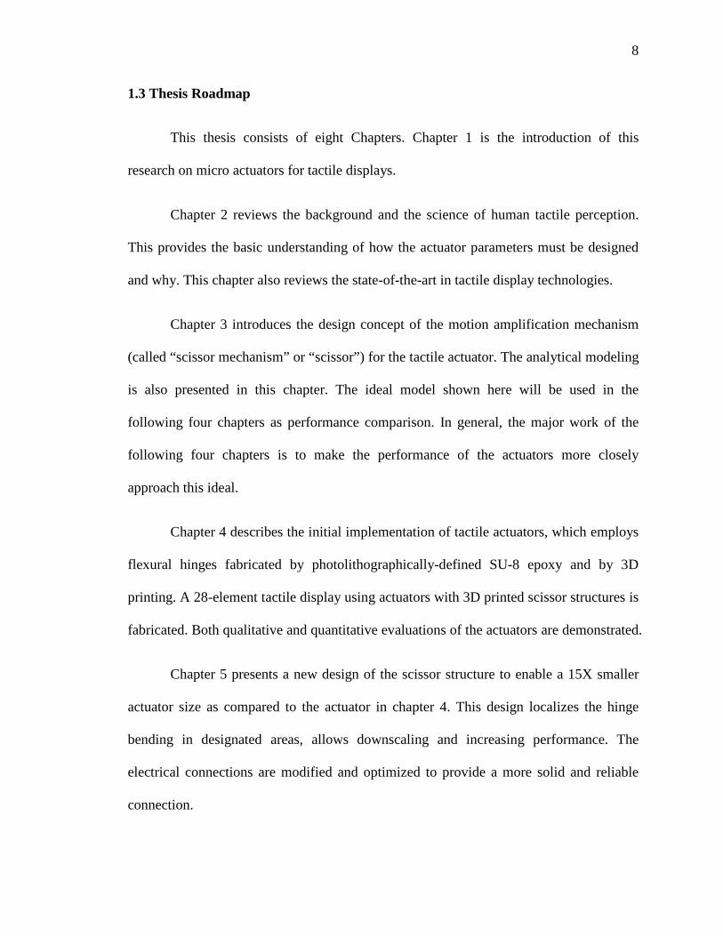
1.3 Thesis Roadmap
This thesis consists of eight Chapters. Chapter 1 is the introduction of this
research on micro actuators for tactile displays.
Chapter 2 reviews the background and the science of human tactile perception.
This provides the basic understanding of how the actuator parameters must be designed
and why. This chapter also reviews the state-of-the-art in tactile display technologies.
Chapter 3 introduces the design concept of the motion amplification mechanism
(called “scissor mechanism” or “scissor”) for the tactile actuator. The analytical modeling
is also presented in this chapter. The ideal model shown here will be used in the
following four chapters as performance comparison. In general, the major work of the
following four chapters is to make the performance of the actuators more closely
approach this ideal.
Chapter 4 describes the initial implementation of tactile actuators, which employs
flexural hinges fabricated by photolithographically-defined SU-8 epoxy and by 3D
printing. A 28-element tactile display using actuators with 3D printed scissor structures is
fabricated. Both qualitative and quantitative evaluations of the actuators are demonstrated.
Chapter 5 presents a new design of the scissor structure to enable a 15X smaller
actuator size as compared to the actuator in chapter 4. This design localizes the hinge
bending in designated areas, allows downscaling and increasing performance. The
electrical connections are modified and optimized to provide a more solid and reliable
connection.

9
Chapter 6 provides the concept and demonstration of a human synovial joint-
inspired, more space-saving pivot hinge for the scissor mechanism. The new structure is
fabricated by a multilayer self-aligned approach to deliver high force and large
displacement. Unlike the scissors in chapter 5 and 4, which employ a flexural hinged
scissor mechanism to provide fingertip stimulation via pure indentation, the presented
system in this chapter uses a pivot-hinged architecture to apply a combination of shear
and indentation forces to the users’ fingertips. The present actuator design also outputs
greater force per unit area of actuator than in chapters 4 and 5.
Chapter 7 shows an advanced design, fabrication, and assembly method that
increases both displacement per unit area and force per unit area. A two-stage, passively
self-aligned, assembly-based process for rapidly creating compact, micro-barrel hinges
with unconstrained rotation is shown in this chapter. These hinges’ ease of fabrication
and functional advantages are demonstrated through design, implementation, and
characterization of a displacement-amplifying, out-of-plane actuator. Most significantly,
the two-stage passive alignment of the barrel-hinged approach provides a rapid,
straightforward manufacturing technique of complex, out-of-plane MEMS architectures.
Chapter 8 summarizes the conclusion of this thesis and suggested future work of
this research.

10
Chapter 2
TACTILE PERCEPTION AND TACTILE INFORMATION DELIVERY
As the largest organ in human body, skin provides the important sensory channel
for humans to receive external stimulations based on touch. By the information perceived
through touch, people can feel and gain the properties of objects like weight, temperature,
textures, and motion etc. In fact, those properties are nerve stimuli to our brain received
by different kinds of receptors in the skin. Mechanical, electrical and thermal stimuli can
stimulate these receptors and cause different information to be conveyed through the
nerves. Technologies for actuators to provide mechanical, electrical or thermal stimuli
have been developed. These include static or vibrational actuation, electrostatic
stimulation, focused ultrasound and more. The design of tactile displays greatly relies on
leveraging of the properties of the skin. Thus it is important to have a deep understanding
of the skin’s sensing and nerve mechanisms.
This chapter aims to review the background biological knowledge of human
tactile sensing in order to give an understanding of how we sense and interact with the
world through the sense of touch, as well as the conventional and state-of-the-art
technologies of tactile actuators for tactile feedback delivery.
2.1 Mechanoreceptors
Human skin contains a variety of different mechanoreceptors (touch receptors),
each with its own structure, placement, frequency response, spatial resolution, adaptation
speed, and necessary magnitude of skin indentation to produce a response.
Mechanoreceptors are the sensing units that lie underneath the very outer skin surface for

11
retrieving stimulations. The presence and spacing of mechanoreceptors varies between
glabrous (naturally hairless) and hairy skin. There are four main types of
mechanoreceptors that react to different kinds of stimuli information such as vibration,
shear, texture, and pressure. These four receptors are called Pacinian corpuscles,
Meissner’s corpuscles, Merkel’s discs, and Ruffini endings (Schultz, 1984). Each
receptor has a similar basic sensing element except that their packaging and depth in the
skin are adapted to their specific sensing purposes.
Figure 2.1 shows a 3D diagram of tactile receptors in the skin. The four
mechanoreceptors can be divided into two major classifications, fast adapting types and
slow adapting types, based on their sensing capabilities. The fast adapting receptors
include Meissner’s corpuscles and Pacinian corpuscles and are only sensitive to
transitions like vibration and fluttering. The slow adapting receptors include Merkel’s
discs and Ruffini endings, and they are sensitive to steady or static stimulations like pure
indentation. The receptors can be further identified as type I and type II based on their
depth below the skin’s surface. Type I receptors are referred to as Meissner’s corpuscles
and Merkel’s discs; they are shallower receptors located at around 0.7 mm to 0.9 mm
below the skin surface. Type II receptors are deeper ones like Pacinian corpuscles and
Ruffini endings, which are often located at about 1 - 2 mm depth below the skin. The
deeper receptors have larger receptive area (Vallbo, 1984).

12
Table 2.1: Characteristics of the four mechanoreceptors. (Choi & Kuchenbecker, 2013)
Receptors Type (Depth)
Type (Adapting speed)
Receptive Field
Frequency (Hz)
Sensing Property
Merkel’s discs I Slow Small 5-15 Pressure, Texture
Ruffini endings II Slow Large 15-400 Stretch
Meissner’s corpuscles I Fast Small 20-50 Stroke, Fluttering
Pacinian corpuscles II Fast Large 60-400 Vibration
Merkel's disks and Ruffini's corpuscles are classified as slowly adapting
mechanoreceptors. Pressure, stretch, and static discrimination are sensed by these
receptors. Higher force and larger displacement are needed to convey static stimuli
sensations (Johnson, 2001). Receptors terminating in Merkel cells are found near the
surface of the skin and have excellent spatial resolution, with an ability to resolve stimuli
separated by as little as 0.5 mm in glabrous skin (Burgess, 1973). Merkel receptors are
the primary receptors that are used in reading Braille. However, their best sensitivity to
skin indentation is found in the range of 5 Hz to 15 Hz, at which frequency a minimum
skin indentation on the order of 50 μm is typically required to produce a response (Vallbo,
1968).
Meissner’s corpuscles, which are located in the shallowest area below the skin’s
surface, are particularly suitable to sense low frequency stroking and vibration.
Meissner’s corpuscles have maximum sensitivity between about 20 Hz to 50 Hz and have
a minimum sensitivity to skin indentation of about 14 μm (Lechelt, 1988). Meissner’s
corpuscles are located with a high density of about 150 receptors/cm2, but they have a
relatively lower spatial resolution and respond rather uniformly across their entire 3-5

13
mm receptive field. Pacinian corpuscles differ from Meissner's corpuscles in their shape,
depth and response threshold. They are more sensitive to the vibrations with frequency
ranging from a few tens of Hz to hundreds of Hz, with the highest sensitivity around 250
Hz (Verrillo, 1963).The highest sensitivity may be found in Pacinian corpuscles, which
have demonstrated sensitivity to less than 1 μm skin indentations around 250-300 Hz and
an effective frequency range from about 60 – 400 Hz (Verrillo, 1963). Pacinian
corpuscles have a large receptive field and can sense larger vibrations from a distance of
on the order of a centimeter away from the receptor. However, smaller vibrations near the
250 Hz frequency of optimal sensitivity produce a response that is localized directly over
the Pacinian corpuscle (Verrillo, 1969), thereby enabling improved spatial localization
with these highly sensitive receptors. The characteristics of mechanoreceptors have a
promising degree of overlap with the known characteristics of microactuators and MEMS
systems. Pacinian corpuscles also adapt faster than Meissner's corpuscles and have a
lower response threshold (Verrillo, 1965). For these reasons, Pacinian corpuscles are
often considered as the better candidate for retrieving the information primarily about
dynamic motion stimuli and high frequency vibrations.

14
Figure 2.1 Tactile receptors in the skin. Blausen.com staff. "Blausen gallery 2014". Wikiversity Journal of Medicine. DOI:10.15347/wjm/2014.010. ISSN 20018762.
2.2 Stimulation Methods and Actuation Technologies
Ideally, the display’s resolution should leverage the approximately one unit per
mm2 spacing of mechanoreceptors in human finger pads (Siegelbaum, 2000) and be
extendable to full 2D. It should be refreshable in real time (i.e., it should refresh at least
as quickly as human mechanoreceptors can react), allowing the information conveyed by
the display to keep up with rapidly changing inputs. The display should also code
information in a way that is easily detected and interpreted so that it is intuitive and easy
to learn to use. The psychophysics literature offers clear insights into humans’ ease of
sensing various types of tactile stimuli (static vs. moving, vibrating vs. quasistatic, and

15
low vs. high amplitude). In particular, humans are much more sensitive to motions and
changing stimuli than they are to static patterns (Downar, 2000), whether those stimuli
are visual, audible, or tactile. The display should therefore code information not only as
static patterns, but also as simulated motion against the user’s finger pads. Finally, its
power consumption should be compatible with portable use, and it should be
manufacturable by efficiently scalable means to ensure that its cost is compatible with the
resources of its intended user base. There are several ways to provide the stimuli for
tactile displays. The stimulation methods can be divided into approximately three
categories: thermal, electrical, and mechanical stimuli.
2.2.1 Thermal
Thermal stimulation or thermal flow is usually used for adding quality
characteristics in the information delivery such as mimicking the color rendering of a
vision system. A 3 x 3 thermal tactile display device with multiple heat sources that can
display temperatures from 5ºC to 55 ºC and produce different temperature field
distributions has been developed (Mao, 2012). Thermal sensation modeling for the
fingertip has been developed, showing that skin is more sensitive to rapid temperature
change, which leads to a difficulty in presenting long time stimulation duration
(Yamamoto, 2004). The combination of both vibrotactile and thermal stimuli is used in
the generation of haptic sensation (Kron, 2003). In spite of its capability of representing
color identification and discrimination, thermal tactile displays alone are not well-suited
to present rich information because of their low spatial resolution and their lower sensing
transition time between on/off states (Jia, 2015).

16
2.2.2 Electrotactile
Electrotactile stimulation uses electrical current flow from electrodes embedded
in the device to deliver stimuli to the sensing nerves of the skin, mimicking pressure or
vibration without any actual mechanical actuators involved (Strong, 1970). A 4 x 4
electrotactile matrix called SmartTouch is developed to selectively stimulate the Merkel’s
discs and Meissner corpuscles. The sensation is generated by electrodes that run electrical
current pulses of 1 - 3 mA with a duration of 0.2 ms through the nerves of the skin
(Kajimoto, 2004). A sensory substitution system that employs electrotactile and
vibrotactile displays was developed in (Kaczmarek, 1991). There are also oral
electrotactile displays. An array of 7 x 7 tactual actuators fabricated on polyimide-based
flexible film was placed on the roof of mouth, to deliver electrotactile stimulation with
relatively low stimulation intensities (Tang, 2003). Although electrotactile systems are
structurally simple and easily controlled, challenges remains in spatial resolution, safety,
comfort level and power consumption.
2.2.3 Mechanical
Mechanical tactile stimulation is the most commonly used method to create
sensation, not only because the mechanoreceptors tend to respond to direct and physical
mechanical stimuli easily, but also because of the finer spatial resolution as compared
with thermal and electrotactile stimulation.
2.2.3.1 Static Indentation
Braille is the most well-known example of static tactile information acquisition.
Braille can be printed on paper or produced on a refreshable Braille reader in which the

17
dots of each Braille cell are driven up and down by an array of stacked piezoelectric
bending beam actuators. Braille is an excellent means of providing text information to
those who are Braille-literate, as long as the information is available electronically as text
or can be scanned using optical character recognition. The most commonly-used
technology for conveying tactile graphics is embossing of images on paper (e.g.
thermoform or microcapsule paper) (Vega-Bermudez, 1991). Refreshable Braille displays
offer a quasi-static Braille display on a refreshed basis by employing extruded pins driven
by piezoelectric bimorph actuators. This provides an opportunity for intensive
information delivery using an electronic device that is more compact as compared with
printed Braille books.
2.2.3.2 Vibration
Skin nerves tend to sense vibration easier than they sense static indentation (Lee,
1999). Fast adapting Pacinian corpuscles are primarily responsible for vibrotactile
perception in human skin. The lower thresholds of force and displacement for vibration
as compared with static indentation make vibrotactile stimulation a widely and well-
researched candidate for tactile displays. Thus technologies have been developed to
deliver vibrations for tactile display. As human beings, we can distinguish successive
pulses with a time gap of 5 ms (Gescheider, 2010), which is even better than our vision
system in which the minimum time gap is 25 ms (Goldstein, 2002). This means that
vibration can be utilized to create rhythm or patterns for information with complex
meaning. Further variation in vibro-rhythm can be realized by changing the amplitude
and frequency.

18
2.2.3.3 Surface Acoustic Waves
Surface acoustic waves (SAW) generated by SAW transducers can stimulate the
skin to provide a sensation of continuous roughness. Both passive and active sensation
capture of SAW tactile devices have been reported (Kotani, 2007; Takasaki, 2005; Nara,
2001). Ultrasonic motors are used for generating vibration that can be directly sent to the
user’s finger, which is described as passive type SAW transducers. In contrast, active
tactile transducers utilize standing waves of a SAW and friction shift to form vibration.
2.2.3.4 Electrorheological and Magnetorheological Fluids
Electrorheological (ER) and magnetorheological (MR) fluids are special classes
of materials that can respond to the electrical field and magnetic field respectively. They
are both colloid suspensions with dielectric or ferromagnetic particles (1-100 µm) that are
sensitive to electric or magnetic potential. Under normal conditions, when there is no
electric or magnetic stimulus to the materials, the ER or MR fluids remain in liquid form.
Upon application of electric or magnetic field, the particles align themselves nearly
parallel to the direction of the fields. This causes the viscosity to change, and the liquids
become solid gels as the field applied increases. Such properties have been used to make
tactile displays (Klein, 2005; Klein, 2004; Liu, 2005).
2.3 Vibrotactile Actuators for Tactile Feedback
Vibrotactile displays have been researched and developed during the past few
decades because mechanoreceptors sense vibration sensations more easily and rapidly
than they sense quasistatic mechanical stimuli. The actuators used to generate vibration

19
range from large scale electric motors to MEMS scale hydraulic pumps. Each has
advantages and drawbacks for tactile displays.
2.3.1Rotary Electromagnet Actuators
Rotary DC motors (Boldea, 1997) are utilized to produce vibrotactile sensation.
The motors rotate when a DC current is applied. An off-centered mass affixed to the
output shaft of the motor (often referred as an eccentric mass) offers the vibration. The
feeling of vibration created by these motors varies linearly with the voltage or current
applied. A small voltage creates a small and slow vibration, whereas a large applied
voltage generates a strong and fast vibration. This type of actuator is the most commonly
used vibrational actuator in toys, game controls and virtual reality tactile devices
(Axonvr). The benefits of rotary actuators include their cost effectiveness, relatively
strong vibration, and relatively lower requirements for electronics. Their drawbacks
include their slow response time, which is usually in the range of tens of milliseconds. In
addition, because the rotation it generates is non-directional, it is also not suitable for
high quality precision tactile feedback. Also, the size of the rotary motor is usually
relatively large, which makes it a poor candidate for high resolution tactile displays.
2.3.2 Linear Electromagnetic Actuators
Linear electromagnetic actuators (LEA) are another main way of using
electromagnetic inputs to generate vibration. When a current passes through the
conductive wires wrapped to form a coil, an electromagnetic field is generated. That field
either pushes or drags a permanent magnet inside the coil, depending on its physical
orientation and the direction in which the current flows into the coil; the motion of the

20
magnet in turn causes a tactile vibration. LEA actuators are also commonly used in
mobile phones because of their low cost and the appropriateness of their compact size for
the mobile phone scale. The actuator only works at the resonant frequency of the system.
Although the LEA reacts faster than a rotary motor, it is still rather slow for a fast
response tactile system. In addition, braking the actuator can be complicated.
2.3.3 Electroactive Polymer
Electroactive polymers (EAP) are a group of polymers that change shape or size
when an electric field is applied. When they change shape or size, a vibration is formed.
Electroactive polymer actuators provide quasistatic millimeter-scale actuations and are
small enough to be arrayed with a pitch of a few millimeters, but they typically have
actuation times on the order of tenths of seconds to tens of seconds (Bar-Cohen, 2004;
Bicchi, 2008). The EAP is robust but slow in refresh rate. In addition, a voltage higher
than 300V is normally needed to activate the actuator, which is not ideal in a portable
tactile device.
2.3.4 Shape Memory Alloy
Shape memory alloy (SMA) actuators are metal alloys that remember their
original shapes; their shapes change under the response to a temperature change, for
example via Joule heating. This effect happens because of reversible phase changing
inside the alloy. Though SMA tactile displays have been developed to provide large
displacement and high force, their slow response times and large power consumptions
make real-time vibrational graphical tactile display almost impossible (Jairakrean, 2009;
Matsunaga, 2005; Mansour, 2015).

21
2.3.5 Piezoelectric Actuators
The piezoelectric effect was discovered in 1880 by two physicists (Jaffe, 2012). It
describes the phenomenon that in a certain group of materials, an electrical potential is
generated when a mechanical load (pressing or squeezing) is applied on the material. In
most crystals like metal, the unit cell that is the minimum repeating structure is
symmetric. In contrast, in piezoelectric crystal structures the unit cell is not symmetric.
Piezoelectric crystals are electrically neutral in their initial state. They can have an
electric polarization when no load is applied (being both ferroelectric and piezoelectric)
or no electric polarization when no load is applied (being purely piezoelectric). When a
mechanical load is applied, the positive and negative charges separate, generating an
electrical potential across the piezoelectric material. This process is also reversible. When
a voltage is applied on the opposing faces of the piezoelectric material, the material needs
to rebalance the electrical charges inside it, which causes a mechanical deformation. In
order to create the piezoelectric effect in piezoceramics, in which the piezoelectric crystal
grains are randomly oriented, the material needs to be heated to high temperature under a
strong electric field in a process called poling. The heat allows more free movement of
the molecules, and the poling directions of each grain are forced into nearly the same
direction under the strong electric field. After the poling process, the piezoelectric effect
is obtained in the treated material.

22
Figure 2.2 Crystal directions in piezoelectric material before and after poling process
The relationship between the mechanical deformation and the voltage applied on
the piezoelectric materials is defined as piezoelectric coefficient, which is mathematically
defined as in equation 2.1:
𝑑 = 𝑠𝑠𝑠𝑠𝑠𝑠 𝑑𝑑𝑑𝑑𝑑𝑑𝑑𝑑𝑑𝑠𝑑𝑑𝑑𝑠𝑑𝑑 𝑑𝑑𝑑𝑒𝑠𝑠𝑠𝑒 𝑓𝑠𝑑𝑑𝑑
(2.1)
Three axes termed as 1, 2, and 3 are used to identify directions in piezoceramic
material. The terms 1, 2, and 3 represent the axis of X, Y, and Z in the spatial 3D set of
axes. The 3 axis is defined as the axis that is parallel to the polarization direction during
the poling process. In practice, the piezoelectric coefficient is described as dij, in which
the subscripts i and j represent the poling direction of the piezoelectric material and the
direction of the mechanical strain, respectively. A larger dij value means that the material
has a greater mechanical deformation under same electric field in the specific direction
defined by i and j. The most commonly used dij are d33 and d31. The term d33 describes a
positive strain in the direction of its length when an electric field is in the same direction.
The term d31 describes a negative strain in the transverse direction as the electric field.

23
Figure 2.3 Diagram demonstration of piezoelectric effect
The piezoelectric effect has been used to produce vibrotactile motion.
Piezoelectric materials can be either solid ceramics or soft gel-like polymers, and they
change shape when a voltage is applied. This process is reversible, so piezoelectric
materials are also often used in sensors to detect mechanical deformation or the
corresponding force applied on the material. Piezoelectric material responds very quickly
(micro seconds) to electrical stimuli, and thus is often used to produce high frequency
vibration.
2.3.5.1 Piezoelectric Bending Beam Actuators
The piezoelectric effect is found not only in piezoceramics, but also in polymers
like PVDF (Polyvinylidene fluoride). Piezoelectric polymers can provide a good pulling
force not a good pushing force because of its mechanical flexibility. It also has a smaller
piezoelectric coefficient compared to piezoelectric ceramic; thus it is not suitable for
applications in which high frequency vibration with reasonable voltage is needed.

24
Piezoelectric actuators may be structured in various ways to produce extensional
or bending actuations. When a single long, thin plate or beam of a piezoceramic is poled
in its thinnest dimension, it forms a piezoelectric unimorph actuator. When a voltage is
subsequently applied across its thinnest dimension, the unimorph undergoes changes in
length and thickness; in other words, it forms an extensional actuator. An alternative
structure, a piezoelectric bimorph actuator, may be created by laminating two unimorphs
together so that the structure’s thickness is doubled. The two unimorphs may be
laminated so that their polarizations are either parallel (called Y-poled) or antiparallel
(called X-poled). When voltages are applied across the two layers of the bimorph, the
bimorph can provide extensional actuation (like a unimorph actuator) or bending (when
one layer is contracting and the other is expanding under the influence of an applied
voltage), depending on polarities of the applied voltages.
Piezoelectric bimorph bending-beam actuators may be used for vibrotactile
applications. The vibration occurs when an alternating voltage is applied on the actuator.
A device called the Optacon (Goldish, 1974) was created in the 1970’s to permit visually-
impaired people to read text from a page without first translating the information into
Braille. The system includes a camera that can be manually scanned across written text;
an image of each character is then transferred into a pattern of vibrating piezoelectric
beams in which the beam tips replicate the pattern of black and white of the character on
the page. The piezoelectric beams are bimorph actuators that vibrate to deliver
vibrotactile sensation. Although the Optacon is no longer in production, existing units are
still in use by a group of people who find its capabilities indispensable. An alternative
integrates piezoelectric bending beam actuators perpendicular to the tactile sensing plane,

25
enabling large bending beam actuators to be tightly packed for fully 2D displays
(Pasquero, 2003). The large amount of piezoelectric material required potentially
increases the cost of this type of architecture, as for other piezoelectric bending beam
actuator systems.
2.3.5.2 Piezoelectric Extensional Actuators
Although most tactile displays that engage the piezoelectric effect utilize bending
actuators, there are some tactile displays that use extensional piezoelectric actuators.
Piezoelectric extensional actuators are not able to provide as large of a displacement as
bending actuators, but with some motion amplification mechanisms, they can be compact
and still efficient. Piezoelectric extension actuators and MEMS technology are also
increasingly being leveraged to create tactile displays, as in (Ninomiya, 2009). Important
challenges nonetheless remain, including spatial resolution, refresh rate, fabrication
complexity and cost.
2.3.6 Pneumatic Actuation
In pneumatic actuation, air pressure changes are used to provide direct or indirect
vibration to the user’s skin. The pressurized air flow directly causes a pressure or acts as
a driver to move mechanical parts to interact with a finger (Kim, 2006; Yoo, 2015).
Pneumatic actuator systems can be compact and light, but they require external air pumps
to generate air pressure, and high frequency output can be a problem for pneumatic tactile
display.

26
2.4 Conclusion
Although refreshable 2D graphical interfaces have tremendous potential for
conveying complex information, it is challenging to create actuators that are compact
enough to be arrayed into an arbitrarily large number of rows and columns while still
being robust, easy to sense, and rapidly switchable. Each of the technologies presented in
this chapter has its own advantages and disadvantages, but none of the current actuators
discussed is optimal for compact, fast response, high resolution graphical tactile display
in terms of the tradeoff between tactile feedback effectiveness, system complexity, power
consumption and cost as shown in table 2.1.
Table 2.1: Comparison of common vibrotactile actuation types
Feedback
effectiveness System
complexity Size Power consumption
Response speed Cost
Rotary Motor Bad Good Bad Marginal Good Good
LEA Marginal Good Bad Marginal Good Good
EAP Good Marginal Good Bad Bad Marginal
SMA Good Bad Good Bad Bad Marginal
Piezoelectric Good Marginal Marginal Good Good Bad
Pneumatic Good Bad Bad Bad Marginal Bad

27
Chapter 3
DESIGN AND MODELING
As described in chapter 2, human finger pads contain multiple types of
mechanoreceptors that respond at different frequencies and vibrational amplitudes. The
receptors that can sense the smallest vibrations (Pacinian corpuscles) have been measured
to detect vibrations of less than 1 µm at frequencies of 250-300 Hz (Verrillo, 1963),
whereas the receptors that sense vibrations at lower frequencies of tens of Hz can more
typically detect vibrational amplitudes of greater than about 10 µm (Verrillo, 1965). In
order to make tactile actuators in a miniaturized size and to leverage sensing by the fast
adapting Pacinian corpuscles, a design that combines the advantages of piezoelectric
actuators’ high frequency response and a mechanism to amplify the deformation to levels
of force and displacement that are readily sensed by fingers will be proposed in this
chapter.
3.1 Device Specifications
The tactile actuating elements should be readily sensed by users with differing
finger sensitivities over a wide range of vibrational frequencies. In addition, finger
sensitivity varies among individuals based on age, health, environment (e.g. ambient
temperature), and experience with tactile sensing. The initial specification for vibrational
amplitude was set to >10 µm to accommodate the wide range of human finger
sensitivities at tens to hundreds of Hz. This threshold has been validated through
laboratory testing of the devices, which will be shown in chapter 4. An amplitude of 10
µm would not be adequate for reading Braille text, which relies on sensing quasistatic

28
dots at least 0.48 mm in height as described in (U.S. Access Board, 2004). However, the
present tactile elements for graphical displays operate in vibrotactile mode rather than
quasistatic mode, enabling detection at lower amplitudes. Because it is common for
individuals to be able to detect vibrations at the few-micron scale, a specification of >10
µm offers ample margin either for a given user’s reduced sensitivity or for sensitivity
variations as the frequency is changed between 10 Hz and 400 Hz. Actuator force may
also matter for sensing; if the tactile element has insufficient stiffness, the force that it
applies to the user’s fingers may be too small for robust detection. Rather than attempting
to create a universal force specification based on limited information, the quantitative
force requirements are instead identified later, during testing, by correlating measured
forces with observations of the user experience.
3.2 Ideal Tactile Element Performance
As mentioned in previous chapters, human are more sensitive to vibrational tactile
stimuli than to quasistatic tactile stimuli, thus the goal of designing the tactile element for
high resolution tactile display is to have a vibrational actuator with compact size. As
firstly introduced in chapter 1, the concept of the proposed tactile actuator employs an
extensional piezoelectric actuator, which has the ability to contract and expand in
response to an applied alternating voltage. A scissor mechanism is anchored to the ends
of the extensional actuator, and it converts and amplifies the lateral motion of the
piezoelectric into vertical motion of the peak of the scissor. When a voltage is applied
across the piezoelectric extensional actuator aligned with the poling direction, the
actuator gets longer and thinner in shape, caused the two ends of the scissor structure
fixed with the actuator moving towards to each other, and the center tip of the scissor

29
rises. When the voltage is applied in the opposite direction with the poling direction, the
material gets shorter and thicker, the center tip of the scissor drops. By applying the
alternating voltage to the actuator, lateral vibration of piezoelectric actuator is generated,
causing center tip of scissor vibrates up and down. The bending beam actuator is not
chosen for our design because it is difficult to achieve force and displacement at the right
levels in a bending beam actuator of reasonable size.
The purpose of modeling and analytically predicting the performance of the
scissor-amplified actuator is to determine whether the new design can provide sufficient
force and displacement for the tactile sensing, and to identify the correct design
parameters for the actuator system. Figure 3.1 shows the ideal tactile element geometry
and a free-body diagram of an ideal scissor structure under an applied vertical load
applied by the user. The structure of figure 3.1 uses pinned hinges, and the approximation
of pinned hinges is used for the modeling below. In practice, the real system sometimes
uses pinned hinges (e.g. chapters 4 and 5) and sometimes does not (e.g. chapters 6 and 7),
depending on its detailed architecture. These variations in the hinge design can contribute
variations between the predicted and observed system performance. For example, the
ideal structure has a finite tactile element stiffness against vertical, user applied loads,
arising from the stiffness of the piezoelectric actuator. However, the ideal scissor offers
zero stiffness against the lengthwise expansion or contraction of the piezoelectric. In
contrast, a non-ideal scissor with for example flexural hinges will have finite stiffness
that opposes the piezoelectric’s motion. In this way, the scissor’s design can impact the
performance of the actuator.

30
Figure 3.1: (a) Configuration and geometric parameters of a tactile element with an ideal scissor with pinned hinges, and (b) transmission of vertical forces applied to an ideal scissor into horizontal and vertical forces that are applied to the actuator.
In the absence of opposing forces from user load, the applied voltage V either
parallel or antiparallel to the piezoelectric actuator’s polarization produces an electric
field of
tVE = (3.1)
where t is the thickness of the piezoelectric actuator. This electric field results in a
lengthwise extension ∆L
tLVdL 31=∆ (3.2)
where L is the length of the piezoelectric actuator and d31 is the piezoelectric coefficient
described in previous chapter. In practice, the voltage is a function of time; it oscillates to
create an oscillating vibration. The peak voltage is described as Vmax. When Vmax is

31
applied, the lengthwise extension also achieves its maximum value of ∆Lmax, which is
given by
tLVdL 31max =∆ (3.3)
The actuator can extend or contract, depending on the sign of the applied voltage. The
scissor mechanism on top of the actuator converts the actuator’s horizontal displacement
into vertical displacement of the peak of the scissor and of the sensing pins as shown in
figure 3.2.
Figure 3.2: Scissor structure converts the actuator’s horizontal displacement into larger vertical displacement.
For a scissor with ideal pinned hinges, a geometric analysis gives the scissor’s
maximum vertical displacement ∆ymax as
, (3.4)

32
where θ is the angle between scissor and actuator as shown in figure 3.1. The magnitude
of the ratio of vertical displacement to horizontal displacement, which is also called the
amplification factor, can be large when the scissor angle θ is small. For example, an
angle of 5º corresponds to an amplification factor of 11, and an angle of 1.25º
corresponds to an amplification factor of greater than 45.
Users have to place their fingers on the center tip of the scissor structure and press
on it to feel the vibration. That force applies a downward load on the actuator. The
actuator’s net displacement then reflects both its electrical drive and the human-applied
force. Users apply loads to the system in the process of sensing the tactile display’s
output. User-applied vertical forces can affect the system’s performance by imparting
forces both to the underlying PZT beams and to the scissor amplifiers. For an ideal
scissor mechanism with rigid arms and pinned hinges, the scissor arms are two-force
members. The net force in a two-force member has to be along its axial direction. When
the vertical component is given (as for a use-applied force of given magnitude), then the
resultant and the horizontal component can be derived as well. The vertical force F
applied at the scissor’s peak produces larger axial forces of F/(2sin(θ)) in the scissor arms.
The axial forces in turn apply vertical forces of F/2 and horizontal forces of Fcot(θ)/2 at
the ends of the PZT beam. The vertical forces can bend the PZT if the PZT is supported
at points away from where the force is applied such as at the center part of the PZT, and
the forces’ magnitude (or the PZT’s resulting deflection) must be limited to prevent
breakage. The horizontal forces tend to stretch the PZT, lowering the peak displacement
of the scissor. In practice, the scissor linkages are not simple two force members when
the joint is not an ideal pinned hinge. For a non-ideal scissor mechanism (e.g. one with

33
flexural hinges rather than pinned hinges), the stiffness of the scissor itself can also affect
the tactile element’s performance. The lengthwise (horizontal) stiffness of the scissor will
apply tensile and compressive forces to the PZT in extension and contraction,
respectively, and tend to oppose the PZT’s actuation. A flexural scissor also has finite
vertical stiffness. For the purpose of analytical modeling to guide the initial tactile
element design, the forces arising from the scissor’s stiffness are neglected. It will be
seen in subsequent chapters that the ideal model provides a useful approximation of the
system’s physics even for the case of non-ideal hinge behavior.
The extensions predicted in equations (3.3) and (3.4) only describe the case in
which the PZT is not also subjected to axial forces. When an axial (horizontal) force is
applied along with a voltage, both the voltage and the force will contribute to the
actuator’s elongation. The axial force that is large enough to completely cancel out the
motion under a given applied voltage is called the blocking force Fb, and it is given by
(Moheimani, 2006)
(3.5)
where w is the width of the actuator and g31 is the actuator’s piezoelectric voltage
coefficient. The piezoelectric stiffness k of the actuating beam is given by the ratio of its
maximum extension to its blocking force,
(3.6)

34
When a voltage V is applied to the piezoelectric actuator along with an axial force Faxial,
the actuator’s lengthwise extension ∆L reflects both electrical and mechanical effects as
(Ronkanen, 2008)
(3.7)
For the case in which Faxial is the user-applied force component Fcot(θ)/2, by substituting
equation (3.6) and (3.3) into (3.7), the lengthwise extension of the piezoelectric actuating
beam relative to its zero-force, zero-voltage length is then given by
(3.8)
The vertical deflection of the top of the scissor relative to its zero-force, zero-voltage
height is given by substituting equation (3.4) into (3.8)
(3.9)
The vertical vibration amplitude ∆yvib is then the difference between the scissor’s
maximum and minimum positions,
(3.10)
A smaller scissor angle offers larger amplification (see the second term of equation (3.9)),
but a too-small scissor angle will reduce the achievable deflection for a given degree of
applied vertical user load. The deflection reduction arises because a smaller scissor angle
increases the magnitude of the force term relative to the voltage term in equation (3.9).
For sufficiently large applied finger forces, sufficiently small voltages, and/or sufficiently

35
small scissor angles, the terms will cancel out completely, so that the highest actuated
position is at the same height as the zero-force, zero-voltage position. The system
requires a protective layer that isolates the user from the system’s inner workings. This
protective layer protects the user from touching the electrical connections of the device; it
also protects the actuators from excessive user-applied pressure. The height of this
protective layer, which is called the cap plate, sets the minimum height at which the user
can sense the scissor’s peak point. Perforations in the cap plate allow the center pin
(sensing pin) of the scissor structure to protrude from the cap plate and interact with the
user’s finger. If the zero-force, zero-voltage position is flush with the cap plate, this will
prevent the scissor’s peak from ever rising above the cap during use.
In practice, the tactile array is assembled so that the sensing pin protrudes above
the cap plate in its zero-force, zero-voltage position. If the sensing pin protrudes
sufficiently far above the cap, applied force does not prevent vibration above the cap; it
just shifts the scissor’s vibrations (and its zero-voltage position) downward. However, a
too-small scissor angle will still compromise performance. As scissor angle is reduced,
the axial force increases until the scissor angle goes negative during use (i.e. the
downward displacement from equation (3.9) becomes larger than the original height of
the scissor’s peak above its lower hinges, so that the scissor turns “inside out” as shown
in figure 3.3). A negative scissor angle would correspond to an alternate stable
configuration in which the pin is recessed. If the scissor becomes stuck in an inverted
position, the system becomes ineffective for tactile information delivery; this situation
must therefore be avoided.

36
Figure 3.3: A too small angle would turn the scissor in an inside out position from the load and stuck in there.
3.3 MEMS-Scale and Milli-Scale Systems Illustration
Two nominal systems are considered for system illustration. In the first nominal
system, which is at the MEMS-scale, the actuator is taken to be 2500 µm × 400 µm × 250
µm (for a total area of 1 mm2). Its maximum positive voltage is chosen to be 200 V, and
its lowest tolerable negative voltage is set at -50 V. The asymmetric actuating voltages
are used for the MEMS-scale actuator to maximize vibrational amplitude within the
piezoelectric material’s limits; the material can tolerate a higher voltage in the poling
direction than it can in the anti-poling direction. The second nominal system is at the
milliscale, with the actuator assumed to be 10 mm × 3 mm × 0.38 mm (for a total area of
30 mm2). Because the larger actuator can provide larger displacements for the same
applied voltage, a smaller actuating voltage can be used. A symmetric voltage amplitude
of +/- 76 V is chosen because it remains within the material’s limits (reaching the same
electric field as 50 V across the MEMS-scale actuator), provides more than adequate
vibrational amplitude, and minimizes the safety concerns that accompany high voltage
drive. The predicted peak displacements under these conditions are 28 µm at an angle of

37
0.79° for the MEMS-scale tactile element and 70 µm at an angle of 0.6° for the milli-
scale tactile element. The scissor angle that offers maximum vibrational amplitude for
this value of applied force is therefore in the range of about 1°, depending on the size
scale. The force assumed for these calculations is 0.1 N. In practice, the applied force
may vary from user to user, and it is preferable to err on the side of somewhat larger
angles to minimize sensitivity to fabrication variations and to ensure that the system is
robust against larger applied forces.
Figure 3.4: Plot of predicted peak-to-peak deflection amplitude calculated using the analytical model for a tactile element with an ideal pinned-hinge scissor as a function of scissor angle for tactile elements at the MEMS and milli scales. The applied voltages are -50/+200 V and ± 76 V for the MEMS and milliscale tactile elements, respectively.
Figure 3.4 plots the vertical vibrational amplitude from equation (3.10) for
MEMS-scale and milliscale tactile elements with ideal pinned-hinge scissors subject to
the constraints that (i) the scissor angle must never go negative and (ii) the magnitude of
the negative voltage must not reach the PZT’s depolarization voltage. The results clearly

38
show that the tactile elements can be expected to provide adequate vibrational
displacements down to the 1 mm2 area of the MEMS-scale actuator.
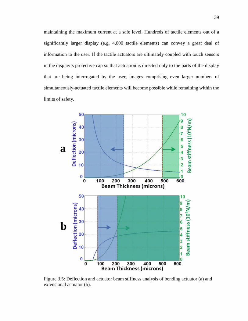
The key advantage of this architecture as compared with the bending beam
actuators of refreshable Braille is that it enables both robustness and sufficiently large-
amplitude actuations (figure 3.5). In figure 3.5, both bending actuator and extensional
actuator are set with same footprint of 1 mm2. The bending beam actuator needs to be
thinner than 250 µm in order to provide a > 10 µm displacement under a 100 V, but it
needs to be thicker than 480 µm otherwise it will break under the finger load. The thick,
short extensional actuator creates large actuation forces while providing excellent
robustness against bending under user-applied load under the same applied voltage. The
scissor amplifier converts the resulting small, in-plane deflections into larger vertical
vibrations. In contrast, a piezoelectric bending beam of comparable length would have to
be thinner than the actuators used here to achieve sufficient vibrational amplitude, and its
thinness would sacrifice robustness against applied forces.
The voltages of up to 200 V required to drive the MEMS-scale tactile element are
large, and the question arises of whether the tactile arrays may be operated safely.
Conventional refreshable Braille displays are driven by comparable voltages and undergo
similar use. To prevent user exposure to high currents under high driving voltages,
Braille displays are often equipped with a 4 mA current limiter. A 4 mA current limiter
applied to a tactile display of the type presented here would permit more than 500 tactile
elements (each 1 mm2 in area) to vibrate simultaneously at 100 Hz, while also ensuring
user safety. Operation at somewhat lower voltages, as figure 3.4 suggests should be
possible, permits an even larger number of tactile elements to vibrate at once while
39
maintaining the maximum current at a safe level. Hundreds of tactile elements out of a
significantly larger display (e.g. 4,000 tactile elements) can convey a great deal of
information to the user. If the tactile actuators are ultimately coupled with touch sensors
in the display’s protective cap so that actuation is directed only to the parts of the display
that are being interrogated by the user, images comprising even larger numbers of
simultaneously-actuated tactile elements will become possible while remaining within the
limits of safety.
Figure 3.5: Deflection and actuator beam stiffness analysis of bending actuator (a) and extensional actuator (b).
a
b

40
Supporting the actuator at its center frees its ends to move in extension and
contraction, but the suspended ends can bend or break under applied loads. The
maximum stress in the PZT under an applied load of 0.1 N was calculated using linear,
analytical models of beam bending and was compared with the material’s expected
failure stress of >60 MPa in pure bending (Fett, 1999). The predicted values of maximum
stress in the PZT were 40 MPa and 26 MPa for the MEMS-scale and milliscale devices,
respectively. Two deflection-limiters can be included for additional safety. First, the ends
of the actuator beams can rest on (or lie just above) the underlying support surfaces to
prevent the piezoelectric beams from bending significantly. Second, the tactile display
can be capped by a perforated plate as described above. The user can sense the pins’
vibration where the pins protrude through the holes, but the cap prevents overdeflection
of the tactile elements under load. The cap also provides electrical isolation and prevents
tactile distraction caused by feeling parts of the system other than the sensing pins.
The modeling in this chapter demonstrated that the design of the extensional
actuator plus the scissor motion amplifier would provide sufficient displacement for the
tactile sensing application.
41
Chapter 4
TACTILE ACTUATORS WITH MONOLITHIC FLEXURAL HINGES
Although the pinned hinge in the ideal scissor structure described in Chapter 3 is
desired, it is technically challenging and potentially costly to implement the pinned hinge
in small (micro or meso) scale systems while maintaining good mechanical properties for
tactile display applications. The design and demonstration of a hinge that can mimic the
ideal pinned hinge in performance while offering ease of fabrication and fast prototyping
are presented in this chapter. The design, fabrication, and characterization of the
milliscale tactile elements that were described in the modeling of chapter 3 are presented
in this chapter.
4.1 Design
The analytical models described in Chapter 3 are only strictly applicable to tactile
actuators that employ ideal scissor elements with pinned hinges. For ease of fabrication,
the present scissors use bending flexures in place of pinned hinges. The conversion of the
ideal, pinned-hinge scissor design to a design that employs bending flexures is carried out
as follows. The scissor angle is chosen to be 5.5° for the reasons described in the
previous chapter; this angle is small enough to offer the specified 10 µm-scale amplitudes
but large enough to improve the scissor’s robustness against turning inside out under
larger applied forces. The lower bending flexures are placed so that they meet the lower
anchor supports at the intended horizontal locations of the lower hinges. The upper
bending flexures are placed so that they meet the central sensing pin at a distance of L/2
from the anchor supports, with L defined as in figure 3.1 Note that the single central

42
hinge of the ideal design is replaced by two flexures, one on each side of the central
sensing pin. This translation of the ideal design to the bending flexure design is
approximate; in practice, the rotation of the bending flexures is distributed along their
length rather than being located at a single point as for a pinned hinge. The vertical
heights of the upper flexures relative to the lower flexures are chosen to ensure that the
line between the point where the lower flexure attaches to the anchor and the point where
the upper flexure attaches to the central sensing pin will create the desired 5.5° angle with
the horizontal. Finally, the nominally rigid scissor arms are designed as straight,
horizontal members for simplicity. The scissor arms do not need to be oriented precisely
horizontally; any relatively rigid structure that connects to the flexures at the appropriate
points and does not interfere mechanically with the other system components will suffice.
Scissors with flexures apply additional axial forces to the actuating beams as
described above in chapter 3, reducing the predicted displacement as compared with ideal
pinned hinge systems. The less-localized bending of the flexures is expected to reduce the
pin’s vibrational amplitude still further. Figure 4.1a shows a diagram of the flexural
scissor along with its integrated sensing pin. The dimensions of the nominally rigid
elements and the flexural hinges are chosen to meet four requirements. First, the scissor
angle must produce vibrational amplitudes that are large enough to be readily sensed.
Second, the scissor’s mechanical stiffness against lengthwise elongation and contraction
should be small enough that the scissor’s spring force is negligible compared with the
blocking force. This criterion ensures that the scissor’s stiffness will cause a minimal
reduction of the pin’s vibrational amplitude. Low lengthwise stiffness also enables the
scissor’s spring force to be neglected in the analytical model as compared with the axial

43
forces resulting from user interaction with the display. Assuming a PZT elongation on the
order of 1 µm and a conservative maximum tolerable scissor force in the axial direction
of 50 mN for the milliscale tactile element, the scissor’s lengthwise stiffness should be
less than 5x10⁴ N/m. Third, the flexural scissor’s mechanical stiffness against vertical
deformation under a user-applied load must be large enough to ensure that the scissor
does not deform excessively in use. Finally, the maximum stress in the scissor under
actuator forces or user-applied forces must be low enough to avoid scissor failure,
including failure by fatigue.
In order to make scissor structures with flexural hinges for the milliscale tactile
actuators, the material that will be used to fabricate the scissors must be chosen. The
material has to be flexible to form the hinge while not being too soft; if it is too soft, it
will not work properly. In this case, two materials were selected: a photopatternable
epoxy known as SU-8 and a 3D printed material known as VeroBlack Fullcure 870.
These materials are chosen because their Young’s modulus values of about 2 GPa
provide suitable structural stiffness. Namely, they are not stiff enough for the flexures to
prevent the scissors from functioning, and they are not flexible enough for the scissors to
collapse under the user’s applied forces); these constraints are described further below.
The length and width of the PZT actuator are set to be 10mm x 3mm; further details are
provided later in this chapter.
Finite element analysis (FEA) is used to predict the performance of the scissors
under actuation and under user-applied loads. The maximum acceptable stress in the
scissor is set to 2.5 MPa, which is more than 20 times less than the scissors’ failure
strengths based on tensile strengths of about 60 MPa and 51 MPa respectively for SU-8

44
and VeroBlack Fullcure 870 (the 3D printed material); the materials’ flexural strengths
are higher. The >20X factor of safety is chosen to ensure a long cycle life without failure
by fatigue. The nominal scissor designs have hinge thickness values th of 300 µm for the
SU-8 hinges and 400 µm for the 3D printed hinges. The hinge widths wh are designed as
1.5 mm and 2.8 mm for the SU-8 and 3D-printed scissors, respectively. The length of
each hinge lh for both scissor types is 800 µm out of a total 9.6 mm scissor length. Each
scissor includes a 6 mm tall sensing pin. Both the SU-8 and 3D-printed scissors have a
nominal scissor angle of 5.5°. The FEA results predict a lengthwise stiffness of
2.5x10⁴ N/m, meeting the design specifications, along with a vertical stiffness of 3x10³
N/m. Figure 4.1b shows the predicted stresses for an SU-8 scissor with the as-fabricated
dimensions when the anchors are brought 0.6 µm closer together, corresponding to the
zero-force displacement calculated from equation (3.3) for an actuating voltage of 95 V.
(It will be seen below that this voltage is larger than is necessary for effective sensing.)
These FEA results are obtained using ABAQUS. The predicted peak displacement of the
scissor is 2 µm (corresponding to a predicted peak-to-peak amplitude of 4 µm). The
maximum stress in this case is predicted to be 1.7 kPa, far below the 2.5 MPa value for
maximum tolerable stress in regular use, and it occurs at the stress concentrations created
by the sharp corners where the hinges meet the more rigid elements. Similarly, FEA
predicts that the maximum stress under a 0.1 N vertical load will be 1.1 MPa, which is
safely below the 2.5 MPa limit. These values meet the design specifications and leave
room for higher stresses due to compound loadings. The FEA results show that the
maximum tolerable peak voltage is determined by the PZT’s electrical limits rather than
by scissor stress. The user-applied load at which an SU-8 scissor with the nominal

45
geometry is predicted to reach the approximately 50 MPa failure stress is 4 N. The
protective cap will therefore play an important role in protecting the scissors from
overload.
Figure 4.1: (a) Diagram of the scissor with flexural hinges and (b) stresses predicted by FEA for an SU-8 scissor when the anchors are brought closer together by a distance equal to the zero-force displacement under 95 V.
4.2 Individual Actuator Fabrication
The individual milliscale tactile actuators include a combination of micro and
milli-scale features. Custom y-poled PZT actuators (Piezo Systems, Inc.) laser cut to 10
mm × 3 mm × 380 µm comprise the in-plane actuators. The scissor amplifiers are
manufactured by two methods, namely photolithographic definition in 1.5 mm thick SU-
8 and 3D printing. The MEMS-based and additive manufacturing approaches are selected
because of their ability to create the scissors’ 300 – 400 µm-thick bending flexures as
well as their anchors, pins, and nominally rigid elements. Manufacturing the scissors in
SU-8 offers the advantage of defining all of the scissors’ features in a single, batch-
manufactured photolithographic step. The single-mask process is enabled by the fact that

46
the scissors’ uniform width is defined by the SU-8’s film thickness, and all of the scissor
features (flexures, pins, etc.) are defined in the plane of the photolithographic mask. The
typically smooth sidewalls of thick SU-8 structures (with roughness measured at less than
one micrometer in (Lee, 2007)) minimize local dimensional variations and the potential
performance variations that they may cause. As discussed previously, FEA analysis
shows that the material properties of both the 3D printed material and SU-8 offer
effective operation for the scissor designs presented here, with sufficiently low material
stiffness to avoid significant loading of the actuators and sufficiently high failure stress to
avoid scissor failure during use. In addition, SU-8’s passive release process also enables a
gentle release from the substrate to avoid damage to these small scissors.
Figure 4.2: Fabrication process of SU-8 scissor structures. See details in appendix.

47
Figure 4.3: Masks for patterning SU-8 scissors (left) and photo of SU-8 scissors on wafer during developing (right).
To pattern the SU-8 scissors, 40 nm of OmniCoat (MicroChem) is spun onto a
silicon substrate in three layers. A 1.5 mm thick double layer of SU-8 2150 (MicroChem)
is spun over the OmniCoat and patterned photolithographically. The Omnicoat is
dissolved to lift the SU-8 scissors off the substrate. The microfabrication process and the
mask design of SU-8 scissors are shown in figure 4.2 and figure 4.3. The 3D-printed
scissors are defined from Veroblack Fullcure 870 UV-curable resin in an Objet Eden 333
3D printer. The 3D-printed scissors are created in array form, with each scissor connected
by snap-off tabs to a central bar as shown in figure 4.4. The as-fabricated hinge
dimensions are 800 µm long x 1470 µm wide x 270 µm thick and 800 µm long x 2900
µm wide x 390 µm thick for the SU-8 and 3D-printed scissors respectively. The
difference in hinge thickness primarily reflects the use of two designs with different
nominal thickness, and to a lesser extent reflects process biases. The difference in scissor
width reflects SU-8 process parameters.

48
Figure 4.4 Schematic view of 3D printed scissors connect by snap-off tabs to a bar.
Much larger individual tactile elements with otherwise similar designs are also
created to identify trends in tactile element performance across size scales. For these
macroscale comparison devices, the actuators comprise commercial, off the shelf y-poled
PZT actuators with dimensions of 30 mm × 3 mm × 380 µm. The actuators are paired
with hand-made flexural scissors comprising layers cut from thin (1 mm) ABS plastic
sheets. A single layer is used to define the flexural hinges, and two layers are laminated
together to form the more rigid scissor arms. The as-fabricated scissor angle of the
macroscale tactile element is 5°. The fabricated actuator is shown in Figure 4.5.

49
Figure 4.5: Fabricated macroscale tactile element.
4.3 Element Connection and Array Fabrication
An array of tactile elements with 3D printed scissors as described above is
fabricated to demonstrate the ability of conveying patterned tactile information. The array
consists of 28 tactile elements, and they are aligned in a repeated “4-3-4-3” formation as
shown in figure 4.7b. The purpose of this element arrangement is to minimize the pitch
between each sensing pin; the pins’ offset arrangement reduces the effects of the high
aspect ratio rectangular footprint shape of each actuator. Although larger arrays of tactile
elements would ultimately be soldered to a base plate (e.g. a printed circuit board), the
devices for single tactile element tests and small array tests are electrically connected by
soldering wires to the nickel electrodes on the upper and lower actuator surfaces. The
scissors are adhered to the actuators with a cyanoacrylate adhesive dispensed manually
through a 1 mm diameter nozzle. For single tactile element testing, to lowest order the

50
alignment of the scissor to the actuator does not affect performance, and no provisions
are made for alignment. Two individual tactile elements made by this method are shown
in Figure 4.6.
Figure 4.6: Photographs of fabricated tactile elements with (a) SU-8 and (b) 3D printed scissors.
For array fabrication, alignment is critical because the sensing pins must align
with the holes in the cap plate. The tactile elements for the arrays are created by the same
method as the individual tactile elements, except that the scissors are mechanically
aligned to the actuators using a reference surface. The reference surface is provided by a
machined plastic plate with walls to align and isolate each actuator. It is referred to as
“slots for PZT actuators” in figure 4.7a. 3D-printed scissors are chosen for array
fabrication because their footprint is nearly identical to that of the actuators, so that
alignment of the elements is straightforward. Twenty-eight electrically-connected
actuators and scissors are then placed into a passive alignment plate in which electrically
insulating mechanical stops control the position of each element to within about 50 µm
and prevent shorting of neighboring actuators. The package and its alignment features are
shown in Figure 4.7. The tactile elements in the array form an offset (staggered) array to

51
minimize pitch. A thin foam interlayer placed between the actuators and the alignment
plate prevents parasitic vibrations on neighboring pins but also reduces the vibrational
signal at the target pin. The electrical wires pass through vias in the alignment plate and
are soldered to an underlying printed circuit board. The alignment plate provides
mechanical support to prevent deflection of the actuator under load. The cap plate retains
the tactile elements in position while providing electrical isolation and protection against
mechanical overload. A mechanical spacer controls the height of the cap plate to ensure
that the pins protrude by approximately 300 µm, and all plates are aligned relative to each
other by a set of alignment pins.

52
Figure 4.7: (a) Diagram of package structure, and (b) photograph of 28-element tactile array during assembly.
4.4 Testing Protocol
The three types of individual tactile elements (two milliscale tactile elements and
one macroscale comparison tactile element) are mounted one at a time on a testing stage
under an optical stereomicroscope so that deformations of the scissors are visible in the
microscope’s viewing plane as shown in figure 4.8a with a zoomed in view in 4.8b.

53
Actuating voltages are applied, and the resulting displacements are measured. Square
wave voltages with a frequency of 0.5 Hz are output by a function generator and
amplified by a factor of 20X by a fixed gain amplifier (Falco WMA-20) to achieve peak
voltage amplitudes of up to 170 V. The voltage is increased in 10 V steps from a starting
value of 30 V to the maximum value of 170 V. Two or three images of each tactile
element in each of its maximum and minimum positions for each voltage are captured
using a microscope camera. The scissor displacement was measured from the captured
images by counting pixels; the pixelization of 1.16 µm for the milliscale tactile elements
and 2.7 µm for the macroscale tactile element dominates the measurement error.
To measure the amplitude of the force that the tactile elements apply when they
vibrate in contact with a rigid surface, the individual tactile elements are mounted on a
second testing stage that is held in the grips of a mechanical tester (Instron 5943) like in
figure 4.9a; a zoomed in view shows the scissor sensing pin against the tester in figure
4.9b. The mechanical tester is preloaded to apply a force of 40 mN to the sensing pin
when zero voltage is applied. A square wave voltage with a frequency of 10 Hz is applied
to the tactile element, and its peak amplitude is increased from 30 V and 170 V in
increments of 10 V. The resulting forces are measured by the mechanical tester’s load
cell. The raw data are post-processed in MATLAB to eliminate signals at frequencies
other than 10 Hz (noise and drift).

54
Figure 4.8: Displacement measurement setup (above) and zoomed-in photo of tactile actuator placed in plane for viewing (below).

55
Figure 4.9: Force measurement setup under Instron (above) and zoomed-in photo of tactile element under pressure load (below).
All four tactile devices (two individual milliscale tactile elements with SU-8 and
3D-printed scissors, one individual macroscale tactile element, and one array of
milliscale tactile elements) are tested by a small group of sighted volunteers to determine

56
the minimum voltages at which vibration can be sensed and (when possible) at which
vibration is comfortable. Although individual tactile element testing is naturally carried
out with single tactile elements, a group of seven adjacent actuated tactile elements is
sensed simultaneously for the array testing. The qualitative testing is conducted through a
testing platform with full protection to both the human tester and the device. A 3D
printed cap plate with holes that only allow the sensing pins to protrude covers the tactile
actuators as shown in figure 4.10. The black and yellow pins in the pictures represent the
actuators with 3D printed scissors and with microfabricated SU-8 scissors, respectively.
Figure 4.10: A 3D printed protective cap with two tactile elements.
Using a protocol approved by Northeastern’s institutional review board (IRB), the
sensing threshold for each tester at each frequency is identified by switching the actuation
of a subgroup of 14 tactile elements on and off at random intervals. The lowest voltage at
which a user who is not looking at the apparatus correctly identifies the beginning and
end of vibration is identified as the minimum detectable voltage. Each measurement is

57
repeated at 20 Hz, 100 Hz, and 250 Hz. The voltages at which the testers report minimum
detectability and comfortable usage levels are then correlated with the measured
displacements and forces at each voltage to determine typical operating values of
displacement and force for each tactile element design.
4.5 Quantitative Measurements
The measured peak-to-peak displacement is plotted in figure 4.11a for the
individual milliscale tactile elements and in figure 4.11b for the macroscale tactile
element; the error bars reflect a +/- one pixel measurement error. Also shown is the
vibrational amplitude predicted analytically from equation (3.4) for a tactile element with
an ideal, pinned-hinge scissor. For the purposes of the analytical calculation, the flexural
hinges are approximated as pinned hinges located on the neutral plane of the flexural
hinge directly adjacent to the anchor support and the central pin. Figure 4.11a also plots
FEA predictions of the vibrational amplitude for an SU-8 scissor with its anchors
displaced by an amount corresponding to the predicted zero-force actuator displacement
at that voltage from equation (3.3). Assuming zero-force displacement again neglects the
effects of the scissor’s small stiffness on the actuator’s in-plane displacement.
The tactile elements with SU-8 and 3D-printed scissors show similar
displacements. For the device with an SU-8 scissor, the displacement ranges from a
minimum of 3 µm measured at 30 V to a maximum of 10.7 µm measured at 170 V. For
the device with a 3D-printed scissor, the displacement ranges from 2 µm to 9.2 µm over
that same range. The slightly smaller displacements of the tactile element with the 3D-
printed scissor are attributed to that scissor’s larger stiffness and spring force due to its

58
greater width and thickness. As expected, the larger macroscale tactile element undergoes
larger displacement than the milliscale tactile elements, with vibrational amplitudes from
11.6 µm to 95.7 µm as the voltage is increased from 30 V to 170 V.
In all cases, the increase in displacement with applied voltage is similar but not
identical to the linear trend predicted by the analytical ideal pinned hinge model. The
analytical prediction overestimates the deflection of all three tactile elements for at least
some applied voltages. The up to 35% difference between predictions and measurements
is attributed to the finite stiffness and non-localized hinge structure of the flexural
scissors. Unsurprisingly, the FEA predicts the deflections of the milliscale tactile
elements more accurately than the analytical model does. The analytical, ideal pinned
hinge model nonetheless offers a useful initial tool for the design of future tactile
elements at various length scales, particularly when it is augmented by FEA in the later
stages of tactile element design.

59
Figure 4.11: Plot of tactile element displacement vs. voltage measured for (a) tactile elements with SU-8 and 3D-printed scissors and (b) macroscale tactile elements. Markers represent the data; error bars represent +/- 1 pixel measurement uncertainty; solid lines represent analytical model predictions of displacement for tactile elements with ideal pinned-hinge scissors; and the dotted line in (a) represents FEA predictions of vertical displacement when an SU-8 scissor’s anchors are displaced by an amount equal to the predicted zero-force displacement at that voltage.

60
Figure 4.12 plots the measured peak-to-peak amplitudes of the milliscale and
macroscale tactile elements’ oscillating forces. The markers represent the measured
forces, and the connecting lines are guides to the eye. Each force measurement is
repeated over 15 to 20 voltage cycles, resulting in 15 to 20 nominally identical force
measurements. The error bars represent the maximum variation that is observed between
nominally identical repeated measurements. Whereas the measured displacements are
similar for the SU-8 and 3-D printed devices and match the models well in all cases, the
measured forces differ widely between the two designs. As expected, the forces from the
macroscale tactile element are largest, reaching a maximum of 69.1 mN at 170 V. The
forces from the tactile element with the 3D printed scissor have intermediate values,
increasing from 6.9 mN at 30 V to 48.7 mN at 170 V. The forces from the tactile element
with the SU-8 scissor are smallest, ranging from 2.3 mN to 14.7 mN. The lower forces
from the tactile element with the SU-8 scissor primarily reflect the SU-8 scissor’s lower
stiffness due to differences in geometry, since the scissors’ Young’s modulus values are
similar. For identical hinge length, the SU-8 scissor’s 31% thinner and 46% narrower
hinge shape will be expected to produce an SU-8 hinge that is 18% as stiff as the 3D
printed hinge, as compared with the observed ratio of 30%. The difference between
predicted and measured force ratios is attributed in part to uncertainties in the Young’s
modulus of the SU-8. The difference in stiffness between the SU-8 and 3D-printed
scissors is observed to have a much greater effect on applied force than it does on
displacement, reflecting the fact that even the 3D-printed scissor’s spring force is small
compared with the PZT’s blocking force at this length scale.

61
Figure 4.12: Measured tactile element force vs. peak amplitude of the applied voltage. Markers represent data; error bars represent scatter in the data; lines are a guide to the eye.
4.6 Qualitative Testing
Figure 4.13 plots the voltages needed to create minimally-detectable and
comfortable vibrations for the volunteer testers as a function of tactile element type and
vibrational frequency; each volunteer is represented by points on the scatter plots. All
three frequencies examined here lie below the resonant frequencies of the system. The
resonant frequency of the milliscale PZT actuator under extensional vibration is
estimated analytically to be on the order of MHz, and the lowest scissor mode is
predicted by finite element analysis to be on the order of a few kHz. The experimentally
studied scissor motions may therefore be treated as quasistatic as compared with the
system’s resonances, so that the vibrational amplitude will be independent of driving
frequency over the studied frequency range. The results can be converted into minimum
detectable displacements and forces by comparison with Figures 4.11 and 4.12, except in

62
cases where the displacement or force corresponding to that voltage cannot be determined
from the measurements presented here. Although the number of testers is small compared
with the thousands of individuals that would need to test the devices prior to the
technology’s adoption, several trends emerge. At all three frequencies, the level of
comfortable vibration amplitude is typically in the range of 2-4 µm. For 3D-printed
scissors, the comfortable level of force is typically around 10 mN, whereas SU-8 scissors
enable comfortable detection at about the 2 mN scale. The macroscale tactile element can
be robustly sensed at forces near 10 mN and displacements near 3-5µm.

63
Figure 4.13: The (a) minimum and (b) comfortable forces needed by volunteer user testers as a function of tactile element type and vibrational frequency.
The difference in necessary force for sensing SU-8 and 3D printed scissors may
indicate that sensing is dominated by vibrational amplitude rather than by force in this
design range. Alternatively, it may indicate that the detailed shape of the sensing pin is a

64
critical determinant of the force required for sensing; the MEMS-based SU-8 sensing pins
have square corners, unlike the 3D printed pins’ more rounded tops. The minimum
detectable levels are of course lower than the values for comfortable usage. Since the
minimum detectable voltages (typically about 10 – 30 V) often lie below 30 V, the
corresponding minimum forces and displacements for sensing cannot be determined from
figures 4.11 and 4.12. (The measurement of force and displacement at lower actuating
voltages is precluded by the resolution limits of the measurement set up.) However, an
extrapolation of the results of figure 4.11 suggests that some volunteers can sense 250 Hz
vibrations at the sub-micron level. Higher frequencies are observed to permit sensing of
smaller forces and displacements, in agreement with the literature (Cholewiak, 1995).
Sensing of the tactile arrays (figure 4.14) is seen to be less robust and requires
higher voltages. For example, at 100 Hz, the volunteer testers require voltages ranging
from 65 V to 80 V with an average of 70 V to comfortably sense the display’s actuations.
Some variation in actuation strength is observed in different parts of the array, suggesting
that fabrication variations can affect the amplitude of the vibrations. In comparison, the
voltage required for comfortable sensing of individual 3D printed scissors at 100Hz
ranges between 34V and 65V with an average of 44 V. If the required displacement for
robust sensing is the same for the array as it is for individual tactile elements, this
suggests that the amplitude of vibration has been reduced by a factor of about 1.4 during
array integration. The difficulty of sensing vibrations in the arrays is attributed to the thin
foam interlayer included in the array package. Although this layer successfully minimizes
parasitic vibrations to neighboring pins, it also degrades vibrational amplitude on the
target pin. Future work should focus in part on minimizing vibrational damping at the

65
target pin while retaining appropriate isolation from neighboring pins.
Figure 4.14: Assembled 28-element tactile array.
4.7 Chapter Summary
In this Chapter, tactile elements based on the actuator plus amplifier design are
shown to be effective at the milliscale. Their measured performance agrees with the
models, with maximum deflections of greater than 10 µm and maximum forces above 45
mN that place the devices well above the sensing threshold. An analytical model based
on ideal pinned hinges over-predicts measured vibrational amplitudes by up to 35% but is
nonetheless shown to be useful for predicting the behavior of tactile elements with
flexural hinges. FEA analysis offers more accurate displacement predictions for design
finalization. The analytical model validation provides support for further downscaling of
the tactile elements to the 1-2 mm2 scale, since the models also predict successful

66
functioning at this scale. At the MEMS scale, the display’s resolution would correspond
to up to 100 tactile elements/cm2, i.e., about the mechanoreceptor density in human finger
pads. The measured performance confirms sensing thresholds of about 4 µm and 2 mN
for the most effective tactile devices.

67
Chapter 5
TACTILE ACTUATORS WITH LAMINATED FLEXURAL HINGES
Monolithically fabricated flexural hinged scissors were introduced in the last
chapter. The minimum footprint of the tactile actuators in chapter 4 is 30 mm2. It is
challenging to scale down the actuator size to for example the 2 mm2 scale by
conventional 3D printing techniques because of the manufacturing limitations. The SU-8
manufacturing process has the potential to be scaled down for the creation of smaller
scissors for tactile elements with few square millimeter areas. SU-8 fabrication can create
thin, high aspect ratio structures such as flexural hinges, even at somewhat smaller scales
than were demonstrated in chapter 4. However, when the target size is 2 mm2, the scaling
limits (mechanical performance, lateral extent, and manufacturability) of the flexural
hinges must be carefully assessed and are expected to place a lower bound on the
scissors’ downscaling. Thus the much thinner flexural SU-8 hinge at the 2 mm2 scale is
expected to pose a challenge.
In this chapter, a new design and process, modeled on that of chapter 4, to reduce
the size (area/element) of this technology by 15X relative to chapter 4 is employed. These
second generation tactile elements employ two layers of lithographically-patterned SU-8
microstructure laminated with a thin film of polyimide and adhesives to form hinged
microscissor motion amplifiers. Including rigid regions between compact hinges ensures
that the actuator’s response to external applied force (e.g. finger force) will be dominated
by the response of the PZT rather than by bending of the amplification element, in
contrast to a fully-flexible amplifier architecture such as in chapter 4. As in the devices

68
described in the previous chapters, the microscissors are coupled to piezoelectric
extensional actuators so that the microscissors convert the actuators’ in-plane motions
into larger out-of-plane vibrations at frequencies of tens to hundreds of Hz (figure 5.1).
The precise trade-off between displacement amplification and blocking force can be
tuned by varying the actuator’s detailed design parameters with details as discussed
below in this chapter.
Figure 5.1: Schematic diagram of a single actuator for a tactile array. The actuator comprises an in-plane PZT actuator with a laminated, micro-fabricated scissor amplifier to convert small in-plane vibrations into 10X larger out-of-plane vibrations.

69
5.1 Design
The microscissor requires both flexible elements (for the hinges) and rigid
elements (for the scissor linkages). The flexible elements are made of polyimide film,
with a Young’s modulus of about 2 GPa. The polyimide extends along the entire length
of the scissor. Because the structure requires bending to be localized in the four hinges as
in figure 5.1, the linkages are made more rigid by the lamination of
photolithographically-defined SU-8 elements onto the polyimide film in the regions that
are not supposed to bend. After the completed microscissor is mounted on the extensional
piezoelectric actuator, contraction and expansion of the actuator bend the scissor’s hinges
so that the center of the scissor rises and falls, as in previous versions of the tactile
actuator device. The offset, interleaved hinge structure leaves ample clearance for the
rigid linkages during bending. The present hinge structure shortens the hinge length as
compared with the devices described in Chapter 4, both in absolute terms and as a
fraction of total actuator length, maximizing the space available for longer linkages that
increase vertical displacement.
The initial mask design of the SU-8 microstructures for photolithography is
shown in figure 5.2. This design maximizes the manufacturable space on the wafer. After
patterning the single-layer SU-8 pattern and releasing it from the substrate, the SU-8 parts
are manually assembled on opposing sides of a double-sided, adhesive-coated polyimide
tape by tweezers handling. Because all parts are separate from each other and the
dimensions of each part are about a few hundred microns, it is extremely difficult to
maintain good alignment during the assembly.

70
To address the challenge of aligned assembly, a second mask is designed. This
mask, which is shown in figure 5.3, defines each part in a position that can be transferred
to the polyimide tape without manual assembly.
Figure 5.2: Initial mask design of the SU-8 micro parts for scissor structure assembly.

71
Figure 5.3: Updated mask design of the SU-8 micro parts for scissor structure assembly.
5.2 Fabrication
The as-fabricated dimensions of the rigid elements for the linkages (figure 5.4)
are 200 µm thick, 3.12 mm long, and 0.67 mm wide, suitable for creation of a tactile
actuator with an area of 2 mm2. Both the upper and lower rigid structures are patterned in
SU-8 2150 by a single-layer photolithography process. The SU-8 is patterned on top of a
15 nm layer of OmnicoatTM to enable subsequent release from the substrate. Two hollow,
rectangular SU-8 clamps are microfabricated separately for use later in one version of the
actuator assembly process. The subsequent assembly of the actuator is shown in figure
5.5. The steps shown in figure 5.5a-5.5f are common to all of the devices described in
this chapter, whereas the steps shown in figure 5.5g-5.5i are specific to the just one
version of the assembly process (the one that is described first).

72
Figure 5.4: Optical micrographs of (a) the 200 µm thick SU-8 structures (rigid elements of the actuator) with 30 µm gaps for hinge bending, and (b) the upper and lower hinge structures implemented in SU-8 for a 3 mm x 0.67 mm micro-scissor.
The details of the assembly process are carried out as follows. A temporary
“carrier tape” made of polyimide with a 38 µm (1.5 mil) layer of silicone adhesive is
adhered to the SU-8 structures while they are still on the wafer, and the OmnicoatTM is
then dissolved to release the SU-8 structures from the wafer. The carrier tape preserves
the relative positions of the SU-8 elements after release. The portion of the carrier tape
bearing the upper SU-8 structures is separated from the portion of the carrier tape bearing
the lower SU-8 structures, as shown in figure 5.5c. The upper and lower SU-8 structures,
still on their respective carrier tapes, are then laminated above and below the thin
polyimide film that comprises the hinge layer. Although the alignment of the upper and
lower SU-8 structures is carried out manually under a microscope for the present devices,
the use of an alignment frame (see chapters 6 and 7) can offer the potential for greater
ease of assembly for future devices. The SU-8 structures are retained on the polyimide
hinge by two layers of adhesive, thereby forming the microscissor. The carrier tape is
then mechanically peeled off of the SU-8/polyimide hinge/SU-8 structure. The
dimensions of the resulting polyimide hinges are 30 µm long, 670 µm wide, and either 25
73
µm, 50 µm, or 125 µm thick, depending on the thickness of the polyimide film that is
used. The short hinge length is set by the gaps between the SU-8 components.
Two adhesives are used. The first is a 50 µm (2 mil) thick low-modulus silicone
adhesive that comes laminated on both sides of a polyimide tape. The second is an
approximately 5 µm thick layer of cyanoacrylate adhesive that is applied manually to the
SU-8 parts before they are laminated onto a plain polyimide tape. The final thickness of
the cyanoacrylate is determined by measuring the thickness of the polyimide/SU-8
composite structure both with and without the adhesive layer; the volume of
cyanoacrylate is also well controlled to prevent application of excess adhesive. The
resulting microscissor is shown in figure 5.6a before the hinges are bent during the
assembly of the microscissors onto the actuators.

74
Figure 5.5: Fabrication process flow of a single actuator for a tactile array: a) pattern SU-8 on wafer, b) transfer SU-8 from wafer to polyimide carrier tape, c) separate the upper and lower SU-8 parts, d) laminate the polyimide film, adhesives and both sets of SU-8 parts, e) peel off the polyimide carrier tape, f) attach the tactile interface pin, g) attach the SU-8 clamps (fabricated separately) to the PZT extensional actuator, h) solder PZT to printed circuit board, and i) adhere scissor to PZT to form actuator. Steps a-f are common to all actuators described here, whereas steps g-i are specific to the packaging approach that utilizes soldering.

75
Figure 5.6: Optical micrographs of (a) an assembled SU-8 microscissor with total thickness of 430 µm, and (b) an assembled single tactile element with electrical connections.
The piezoelectric extensional actuators are custom-cut, y-poled PZT actuators
with dimensions of 3 mm x 0.67 mm x 0.38 mm (Piezo Systems, Inc.); the y-poling
allows the actuators to be driven by application of a voltage between the upper and lower
electrodes of the piezoelectric. The microscissors must then be mounted on the actuators.
The overall lengths of the two microscissors are designed to be slightly longer than the
length of the PZT actuator, by 120 µm. When the ends of the microscissor are aligned
with the ends of the PZT actuator, the hinges form a starting (unactuated) angle of 9°
between the scissor linkage and the PZT. The angle is selected as a compromise between
the degree of displacement amplification (which increases at smaller angles) and the
blocking force of the actuator (which increases at larger angles) as described in chapter 3.
The scissors are mounted to the actuators by two techniques, each of which is
designed to enable a different approach to packaging and electrical connection. In the
first approach, which is similar to the techniques of chapter 4 and is shown in figure 5.6b,
the actuators are electrically connected by soldering narrow wires directly to the upper

76
and lower electrodes of the PZT actuator. Because soldered wires do not create a fully
planar connection, clearance is required both above and below the PZT actuator. The
necessary clearance is implemented by sliding the two hollow, rectangular SU-8 clamps
with wall thickness of 200 µm onto the ends of the PZT actuators. The clamps must be
aligned with the ends of the actuators to ensure proper registration of the components.
While the clamps are temporarily displaced toward the center of the actuator,
cyanoacrylate adhesive is applied to the ends of the actuator. The clamps are then
returned to the ends of the actuator, where they are mechanically registered with the ends
of the PZT. Adhesive remains in the 20 µm gaps between the surfaces of the clamps and
the surfaces of the PZT, ensuring strong bonding. In addition to providing clearance for
the electrical connections both above and below the PZT actuator, the clamps serve as an
interface between the actuator and the scissor. The center of the actuator is soldered to a
printed circuit board, creating electrical connection and mechanical support. The top of
the PZT is grounded via a second soldered connection. A separately-fabricated SU-8
sensing pin is also attached with cyanoacrylate adhesive to the scissor’s central element
to create the sensing interface. Figure 5.6b shows a fully-assembled actuator created
using this packaging and electrical connection approach.
In the second packaging approach, each tactile actuator is electrically connected
to its drive voltages by two planar metal strips. One passes beneath the PZT actuator to
contact its lower actuating electrode, and the other passes between the PZT actuator and
the microscissor to contact the upper ground electrode. The advantage of this approach is
its scalability for larger arrays in a row/column architecture. The disadvantage of this
approach is that external supports are required for each tactile element to ensure that the

77
metal strips remain in contact with the electrodes. These external supports, which are
shown in figure 5.7, potentially increase the spacing between elements of a tactile array
and reduce the array’s spatial density.
In the implementation of the second packaging approach that is shown here, the 2
mm2 actuators are packaged in an external support that is even larger than what would be
required. The use of this up-scaled interface hardware provides an effective
demonstration of the second approach for electrical connection, but it does not represent
the limits of close-packing that may be achieved with this approach. For the second
packaging approach, the clamps used in the first approach are not applied to the
piezoelectric extensional actuator. The clamps are omitted because the actuator is
intended to be flush with the underlying electrode; clearance is not needed to create the
electrical connections in this case. Electrical connection to the lower electrode of the PZT
actuator is made by an aluminum strip running lengthwise along the tactile element. The
upper electrode of the PZT actuator is contacted by a thin (0.1 mm) strip of spring steel
running perpendicular to the element’s lengthwise direction, between the actuator and the
scissor. Spring steel is used because its high stiffness enhances the downward force
applied to the actuator, ensuring good electrical contact. In addition to making the
electrical connection to the top of the element in a way that may ultimately be scaled to a
full row/column architecture, the steel strip can act as a mechanical restraint to hold the
center of the tactile element in its proper position in an array. However, for the present
device, conductive epoxy applied between the bottom surface of the PZT and the lower
aluminum strip ensures that the center of the PZT will be the neutral point when the
device is actuated. The tactile actuator is surrounded by two C-shaped enclosures that can

78
be set at a height to protect the actuator from over deflection in case of excessive finger
load.
Figure 5.7. Schematic view (not to scale) of a tactile actuator with metal strips forming the electrical connections. The metal strips and the actuator are positioned relative to each other by a 3D-printed actuator support.
Figure 5.8. Photograph (left) of a tactile actuator with metal strips forming the electrical connections and packaged in a 3D-printed holder. The close up photograph at right shows the details of the electrical wiring approach.

79
5.3 Experiments and Results
The deflection and blocking force of each of the six actuators listed in Table 5.1
are characterized. The actuator parameters are chosen to capture the dependence of
performance on polyimide hinge thickness, on the type of adhesive used to attach the SU-
8 rigid elements to the polyimide hinge, and on the packaging/electrical connection
method. Two nominally identical devices are also measured to characterize repeatability.
To measure deflection, the individual actuators are mounted on a testing stage under an
optical stereomicroscope so that the deformations of the scissor are visible in the
microscope’s viewing plane. A square wave bipolar AC voltage with a frequency of 0.5
Hz is output by a function generator, amplified, and applied to the device. The voltage
amplitude is increased in 10 V steps from a starting value of 50 V to the maximum value
of 170 V. The maximum peak voltage is below the PZT’s maximum allowable voltage
and reflects the limits of the test electronics rather than the limits of the device. The tip
of the actuator moves under the applied voltage, and a microscope camera captures two
or three images of the actuator in its maximum and minimum positions for each voltage.
The actuator’s displacement is measured by pixel counting in the captured images, in
which each pixel is 0.45 µm. Displacement values are recorded for voltage values on
which the pixel count increments by a full pixel, avoiding the need for interpolation.

80
Table 5.1. Actuator parameters
Actuator # Adhesive type Polyimide thickness Electrical connection
1 silicone 25 µm metal strips
2 silicone 25 µm soldered
3 cyanoacrylate 25 µm soldered
4 cyanoacrylate 50 µm soldered
5 cyanoacrylate 50 µm soldered
6 cyanoacrylate 125 µm soldered
To measure the amplitude of the force that the actuators apply when they vibrate
in contact with a rigid surface, the individual actuators are mounted on a second testing
stage that is in turn mounted to the grips of a mechanical tester (Instron 5943). The
mechanical tester applies a compressive preload of 40 mN to the sensing pin when zero
voltage is applied to the actuator. A square wave bipolar voltage with a frequency of 10
Hz is applied to the actuator, and its peak amplitude is increased from 50 V to 170 V in
increments of 10 V. The resulting forces are measured by the mechanical tester’s load
cell.

81
Figure 5.9. Plots of (a) the measured vibrational amplitude and (b) the measured force output by the 2 mm2 tactile elements with various adhesives, layer thicknesses, and packaging methods vs. applied voltage.
The measured peak-to-peak displacement and the measured force are plotted in
figure 5.9. The solid line represents the displacement predicted analytically for the
simplified case of an ideal microscissor with pinned hinges as in chapter 3. The dashed
lines with markers represent measured data with different thicknesses of polyimide,
different adhesives, and different packaging techniques. The results show that
displacement is increased for the actuators with thinner polyimide hinges and that force

82
output is typically increased for the actuators with thicker polyimide hinges. At a
polyimide hinge thickness of 25 µm, the low-modulus silicone adhesive offers greater
displacement than the cyanoacrylate adhesive, whereas the cyanoacrylate adhesive
effectively increases the force applied by the actuator. The deviations of at most 4%
between the measured displacements and between the measured forces of the two
nominally identical actuators (with 50 µm hinge thickness, cyanoacrylate adhesive, and
soldered connections) are similar to the deviations of at most 6% that are measured
between the two actuators that are packaged with soldered and metal strip connections
(with 25 µm hinge thickness and silicone adhesive). These results indicate that the
packaging technique does not significantly affect the performance of the actuator.
The actuator with a 125 µm thick polyimide hinge adhered by cyanoacrylate
adhesive has a maximum displacement of 3.3 µm and a maximum force of 5.3 mN,
corresponding to a displacement per unit of actuator area of 1.6 µm/mm2 and a force per
unit of actuator area of 2.6 mN/mm2. This performance compares favorably with the
results described in chapter 4, which yielded a displacement and force per unit of actuator
area of 0.3 µm/mm2 and 1.6 mN/mm2, respectively. Its force output also compares
favorably with (Xie, 2014; Felder, 2015; Yosefi, 2014; Kyung, 2007), which yielded
forces per unit of actuator area of 0.96 mN/mm2, 1.1 mN/mm2, 0.9 mN/mm2, and 0.6
mN/mm2, respectively. Furthermore, the actuator’s performance may be optimized for
different applications by varying the layer thicknesses.

83
5.4 Chapter Summary
The design, fabrication, and performance of a set of compact tactile actuators that
have a 15X smaller footprint than previous generations of actuators in chapter 4 but still
achieve displacements of > 3 µm and forces of > 5 mN are demonstrated in this chapter.
The maximum peak voltage of 170 V applied here is below the PZT’s maximum
allowable voltage, indicating that the maximum measured displacement and force are
lower bounds on the actuator’s performance. The measured performance corresponds to
values of force per unit area and displacement per unit area that are 5.3 times and 1.6
times those described in Chapter 4, respectively. The current actuators’ performance is
enabled by the use of a laminated hinge architecture that maximizes the length available
for the scissor linkages in a compact area. The performance of the actuators is shown to
depend on the details of the microscissor design. Varying the thickness of the polyimide
hinge layer provides an effective means of tuning the actuators’ force and displacement,
and laminating the layers with a thin layer of cyanoacrylate adhesive instead of a more
compliant silicone adhesive optimizes force output at the cost of a slight decrease in
displacement. Overall, however, the measured displacements are close to predictions
based on an ideal pinned-hinge scissor. In addition, the actuator performance was shown
to be largely independent of the technique used for packaging and electrical connection.

84
Chapter 6
TACTILE ACTUATORS WITH PIVOT HINGES
The last two chapters introduced and demonstrated two approaches for
magnifying small in-plane actuations into larger out-of-plane vibrations using scissor
amplifiers. In both chapters, tactile actuators used piezoelectric extensional actuators and
scissor amplifiers manufactured in whole or in part from single layers of lithographically-
patterned SU-8. These designs simplified the ideal hinges of a scissor mechanism to a set
of thin flexural hinges defined in SU-8, in one case combined with polyimide tape. An
advantage of these approaches is their ease of fabrication; a disadvantage of these
approaches is that the hinge occupies a large portion of the actuator length, thereby
limiting the length of the scissor linkages. Since the amplitude of the vertical
displacement is proportional to the length of the scissor linkage, the loss of linkage length
is detrimental to the actuators’ performance. The research in this chapter is motivated by
the need for a more compact hinge architecture that maximizes the scissor linkage length
in a limited space.
6.1 Design and Fabrication
The concept of the current generation of tactile actuator is like that in chapters 4
and 5, in that the structure comprises a piezoelectric extensional actuator along with an
SU-8-based scissor mechanism to amplify its motions into larger displacements and
smaller forces. However, the hinge’s structure and manufacture are entirely different.
Inspired by the human synovial joint, a more space-saving pivot hinge was proposed for
the present device’s scissor amplifier. The pivot hinge employs a C-shaped housing with

85
a pivot that rotates inside the housing. In chapters 4 and 5, the flexural hinge makes the
tactile element move purely up and down so that it provides fingertip stimulation via pure
indentation. In contrast, the present system uses the new pivot-hinged architecture to
apply a combination of shear and indentation forces to the users’ fingertips. At each end
of the piezoelectric actuator, the rotating pivot forms the planar equivalent of a ball and
socket joint. The two pivots connect to rigid linkages, the tips of which connect to each
other by a third pivot/housing assembly (figure 6.1). A pin protrudes from the central
housing. When voltage elongates the piezoelectric actuator, the pivots rotate so that the
pin moves in a combination of amplified up-and-down and side-to-side motion. The ratio
of the pin tip’s displacement to the horizontal PZT displacement is called the
amplification factor and can be tuned by adjusting the initial angle between the scissor
and the actuator.
Figure 6.1: Schematic diagram of the pivot/housing structure of the motion amplifier.

86
The pivots are “capped” at both ends to prevent the pivot from slipping out of the
housing. Because the caps are wider than the pivot, fabricating them monolithically with
the pivot would involve fabricating re-entrant SU-8 structures and protecting the
underlying SU-8 layers from unintended exposure during subsequent patterning. This
approach would introduce a large number of process steps and would decrease overall
yield via the concatenated attrition of each step’s process yield. To avoid this decrease in
yield, the SU-8 mechanism is instead fabricated quickly and simply by a self-aligned
process (figure 6.2) in which a thin SU-8 “alignment frame” aligns the caps with the
pivots in the functional layer. The caps, pivot/housing layers, and alignment frames are
fabricated separately on silicon substrates coated with OmniCoatTM release layers. The
alignment frames are made of one layer of 100 µm thick SU-8 50, and the pivot and cap
are made of two layers of 200 µm thick SU-8 100. The main functional parts, including
the C-shaped housings, scissor linkages, and pin, are patterned in a 550 µm thick layer of
SU-8 2150.

87
Figure 6.2: Self-aligned fabrication and assembly process for the SU-8 motion amplifier.
To pattern each SU-8 structure, a release layer of 15 nm thick OmniCoatTM is first
deposited on the Si substrate. For each die, three capped pivots are defined via successive
exposure of two SU-8 layers followed by a single development step. The relative
positions of each die’s three capped pivots on the wafer match the relative positions that
are required to bond them to the functional layer as shown in figure 6.3a (housings,
scissor linkages, and pins). Figure 6.3b and 6.3c show the mask design of two layers of
capped pivots. However, if the capped pivots are released from the structure, this

88
alignment will be lost.
a
b c

89
Figure 6.3: Mask design for microfabrication of the scissor functional layer (a), cap (b), pivot (c), and alignment frames (d).
To prevent loss of alignment upon release, the capped pivots are first adhered to
an alignment frame; the mask design for the alignment frame is shown in figure 6.3d. The
alignment frame comprises three hollow rings (sized so that the pivots can protrude
through their central holes) that are attached by 50 µm wide breakaway tethers to an outer
frame. After the frames are released from the wafer on which they were fabricated,
approximately 5 µm thick cyanoacrylate adhesive is applied manually under a stereo
microscope to the rings. Each frame and its pivots/caps are adhered in a self-aligned
manner by placing the frame on the pivot under the stereo microscope. The resulting
“first level assemblies” are released from the substrate by dissolving the release layer.
d

90
Adhesive is then applied manually using sharpened wood stick to the protruding
ends of the circular pivots in the first level assembly. This adhesive will be used to bond
the portion of the pivot that was fabricated with the cap to the portion of the pivot that
was fabricated in the functional layer with the housing and scissor linkages. The first
level assembly is flipped over, aligned to the pivot/housing functional layer under a
stereomicroscope, and adhered to the functional layer to form a second-level assembly.
The diameter of the pivot is smaller in the cap/pivot layer than it is in the pivot/housing
layer. Its smaller diameter increases tolerance for misalignment in this step. The second-
level assemblies are released from the substrate by dissolving the release layer. For
fabrication of the present devices, care was taken during assembly to ensure that the
housings did not slip off of the pivots at this stage. In the future, a frame with breakaway
tethers may be attached to the pivot/housing layer for added robustness.
A second set of capped pivots must be applied to the opposite side of the
functional layer to prevent the pivot from slipping out in either direction. A second
cap/pivot/frame assembly is aligned with and adhered to the second side of the functional
layer using the same process as was described above. Finally, the tethers that connect the
caps to the alignment frames are snapped off to release the micro scissor motion amplifier.

91
Figure 6.4: Optical micrographs of pivot/housing structure with nominal pivot-to-housing gaps from 10µm to 100µm.
Pivot/housing structures fabricated with nominal pivot-to-housing gaps of 10 µm,
20 µm, 40 µm, 50 µm, 70 µm and 100 µm are shown in Figure 6.4. The range of gap
dimensions is included to optimize the displacement and force output from these devices.
The dimensions of the pivot, scissor linkage, and housing determine the pivot’s angular
range.
The assembled SU-8 scissors are adhered to 5 mm x 2 mm (10 mm2) and 3 mm x
0.67 mm (2 mm2), y-poled PZT actuators to form the final tactile actuators (Figure 6.5).
Cyanoacrylate adhesive is applied manually to the two anchors of the scissor before
attaching it to the actuator. The overall distance between the two ends of the scissor in its
flat position is designed to be larger than the length of the PZT actuator. The edges of the
scissor’s anchors are mechanically aligned with the ends of the PZT actuator during
assembly. This passive mechanical alignment ensures that the scissor forms an upside

92
down V-shape above the actuator with a starting (unactuated) angle of 8° between the
scissor linkage and the actuator.
Figure 6.5: Photographs of (a) 10 mm2 and (b) 2 mm2 assembled actuators.

93
Aluminum strips are adhered to the top and bottom surfaces of the PZT’s nickel
electrodes with conductive epoxy. The aluminum provides electrical connection on both
sides of PZT actuator. The conductive epoxy applied between the bottom center of the
PZT and the lower aluminum strip also helps to lock the PZT actuator down to the
substrate, ensuring that the center of the PZT will be the neutral point when the device is
actuated. Unlike in the schematic diagram of Figure 6.1, the implemented device includes
a protrusion (called the “stand”) beneath the center pin. In normal use, the stand is
separated from the actuator by a small gap. If an extreme load is applied, for example by
the user’s finger, the stand protects the scissor from over-deflection and breakage. A
pattern of protrusions also extends out from the side of the central pin, similar to the teeth
of a key. The pattern of the key teeth indicates which device design parameters are
implemented in a given structure.
6.2 Experiments and Results
The pivots with as-designed gaps of 10 µm, 20 µm and 40 µm do not consistently
move freely in the C-shaped housing. Thus the tested scissors are those with gaps greater
than 50 µm. To measure the total deflection of a scissor’s central pin, the device is
mounted on a testing stage that holds the device sideways, so that its deflection is visible
in the horizontal viewing plane of an optical stereomicroscope. A square wave bipolar
AC voltage with frequency of 0.5 Hz is generated by a function generator (BK precision
4040A), amplified by a voltage amplifier (Falco WMA-02), and applied to the
piezoelectric actuating beam. The peak amplitude of the applied voltage increases from
50V to 170V with a step size of 10V. The maximum peak voltage is below the PZT’s

94
maximum allowable voltage and reflects the limits of the test electronics rather than the
device. The microscope captures images when the central tip is in each of its two actuated
positions (i.e. maximum positive actuation and maximum negative actuation). Two to
three images were captured in each actuated position, and the difference between the two
positions represents the displacement of the tip. The displacement is measured by pixel
counting in the images, where each pixel is equal to 0.3 µm. To avoid the need for
interpolation, the displacement values are only included in the graph of the results for
voltage values at which the pixel count increments by a full pixel.
The force output of each device is measured by mounting it on a second stage that
is affixed to a mechanical tester (Instron 5943). The tip of the scissor contacts the
mechanical tester with a preload of 40 mN when null voltage is applied; this simulates
the circumstance in which the device is subject to a finger load. A square wave of bipolar
voltage with a frequency of 10 Hz is applied to the actuator; the voltage’s amplitude
increases from 50 V to 170 V with a step size of 10 V. The resulting forces are measured
by the mechanical tester’s load cell.
Figure 6.6 plots the measured vibrational amplitude vs. voltage and the measured
force vs. voltage for each of the tested devices. The dashed lines represent the
displacement predicted analytically for each geometry for the simplified case of an ideal
microscissor with ideal, zero-clearance pinned hinges (as in chapter 3). The red and green
lines represent the 10 mm2 and 2 mm2 pivot-hinged devices, respectively, whereas the
blue line represents the 3 mm x 0.67 mm flexure-hinged device from chapter 5 for which
the distance between the hinges is smaller than in the present 2 mm2 devices. The markers
represent measured data. The results show that for each actuator, displacements increase

95
linearly or nearly linearly with increasing voltage. The displacement is largest for the 10
mm2 device, as expected. Although the measurements for pivot-hinged devices generally
agree well with the predictions, the ideal hinge model uniformly overpredicts the
displacement of the current pivot-hinged devices. Many factors come into play in
interpreting the effects of increased clearance. Increased clearance is expected to shorten
the effective length of the scissor linkage. It also widens the maximum distance between
the outer edges of the pivot housings. Both of these effects could decrease the scissor’s
effective angle, thereby increasing its displacement. However, a larger-diameter scissor
housing also permits more side-to-side motion of the pivots within their housings. Lateral
motion of the pivot within the housing is hard to predict exactly; it will depend on the
detailed geometry and surface finish of the pivot/housing surfaces. If the pivots do slide
within their housings during the piezoelectric actuator’s driving actuation, then the real
in-plane extension of the scissor can be less than the in-plane extension of the underlying
piezoelectric actuator, resulting in lower vertical displacements. This effect is expected to
be more pronounced for housings that have larger clearance and the lower curvature that
comes with a larger radius, and it is consistent with the observed reduction in
displacement for larger clearances. The smaller displacements of the device with 100 µm
clearance are also reflected in a sparser data set for that device, since the data do not
interpolate between pixels. However, all of the pivot-hinged devices outperform the
comparably-sized flexure-hinged devices of chapter 5; their superior performance is
attributed to the greater functional distance enabled by compact pivot hinges. The force
measurements of figure 6.6b follow a trend similar to that of the displacement
measurements, with larger devices, devices with smaller clearances, and devices with

96
compact pivot hinges offering the highest force output.
The maximum measured displacements of 9.8 μm and 5.5 μm and the maximum
measured forces of 9.6 mN and 5.9 mN for pivot hinged actuators of 10 mm2 and 2 mm2,
respectively, correspond to displacements per unit actuator area of 0.98 µm/mm2 and 2.25
µm/mm2 and forces per unit actuator area of 0.96 mN/mm2 and 2.95 mN/mm2,
respectively. These results exceed the vibrational tactile sensing thresholds for
displacement and force of 4 μm and 2 mN as reported in chapter 4.
Figure 6.6. Plots of the measured displacement (above) and measured force (below) vs. applied voltage.

97
6.3 Chapter Summary
The design, fabrication, and characterization of a set of compact tactile actuators
that have areas of 10 mm2 and 2 mm2 and achieve displacements of 9.8 μm and 5.5 μm
and forces of 9.6 mN and 5.9 mN respectively have been demonstrated in this chapter.
The maximum peak voltage of 170 V applied here is below the PZT’s maximum
allowable voltage, indicating that the maximum measured displacement and force are
lower bounds on the actuator’s performance. The performance of the actuators is shown
to depend on the details of the microscissor design, with larger clearance resulting in both
reduced displacement as compared with predictions for a zero clearance hinge and lower
output force. However, a nominally 50 µm clearance works well, providing 80% to 95%
of the ideal displacement while enabling consistently smooth rotation of the pivot within
the hinge. These advances are enabled by a self-aligned assembly process that eliminates
the need to fabricate re-entrant SU-8 multilayers. The presented actuator design also
outputs greater force per unit area of actuator than in chapter 5 and in (Felder, 2015;
Yang, 2007; Park, 2011), with 2.4X, 4.3X, and 22X greater force/area than in (Felder,
2015), (Yang, 2007), (Park, 2011), respectively.

98
Chapter 7
TACTILE ACTUATORS WITH BARREL HINGES
In the last chapter, a pivot hinge was investigated to replace the flexural hinge in
the micro scissor mechanism. It shows improvements in both force and displacement per
unit area for the tactile actuation. However, the pivot hinge has a limited range of rotation,
so that it does not fully mimic the performance of real, ideal pinned hinges. The goal of
this portion of the research is to better mimic the performance of real, ideal pinned hinges
at this size scale. This technology will advance not only micro tactile actuators, but also
other robust, low-cost MEMS scale systems.
Micro hinges can permit large angular motions in MEMS actuators, but making
conventional hinges scalable down to the microscale while maintaining good mechanical
properties can be difficult. Surface micromachined, pinned hinges are well known (Pister,
1992), but the required investments of time and resources for conventional silicon-based
microfabrication are considerable. Flexural hinges as in chapter 5 offer a rapidly-
fabricated, low-cost alternative, but their finite stiffness and spatially-distributed rotation
prevent ideal pinned-hinge behavior. The pivot hinges of chapter 6 better maintain the
ideality of pinned hinges while reducing fabrication cost and complexity. The resulting
minimum nominal clearance of 50 µm separates the pivot from its housing, but the
hinge’s single-layer fabrication introduces significant taper and side play to the hinge’s
geometry and motion, allowing the pivots to tilt and shift within their housings and
limiting ideal hinge function.
In contrast, this chapter presents tactile actuators that feature barrel hinges in

99
which the pins are defined in separate layers from their housings. The assembly of
(sometimes multipart) pins into housings not only minimizes tilt and reduces side play by
a factor of >3X as compared with the pivot hinges of chapter 6 but also provides robust,
fine-scale self-alignment for straightforward assembly. The design, fabrication,
characterization, and performance of tactile actuators based on this technology are
described below.
7.1 Design
The tactile actuator employs a scissor-based, micro motion amplification
mechanism as in chapters 3-6. The implementation of the barrel hinge-enabled micro
motion amplifier into a tactile actuator is shown in figure 7.1. As in previous versions of
the tactile actuator, when the underlying PZT actuator contracts, the micro motion
amplifier converts the PZT’s small horizontal displacement into larger vertical
displacement. Similar to the pivot-hinged design of chapter 6, the actuator’s central pin
combines up-and-down motion with side-to-side motion. Unlike the previous versions of
the tactile actuator, the present scissor amplifier is designed with recessed anchors that
create end stops and passively align the scissor amplifier to the PZT actuator. The present
architecture is also distinguished by the ideality of the barrel hinges that enable its motion.

100
Figure 7.1: Schematic diagram of a barrel-hinged micro motion amplifier mounted on a PZT extensional actuator.
7.2 Fabrication
Like the pivot-hinged structures of chapter 6, the present scissor mechanisms are
fabricated from a set of simpler SU-8 structures that are then assembled together to form
the more complex, final scissor architecture. Figure 7.2 shows the fabrication of one of
the amplifier’s 3-layer SU-8 plates; see the appendix for the detailed fabrication process.
The plate shown includes two rigid scissor linkages, a tactile interface pin, and parts of
the hinges that connect the linkages to each other and to the supports.

101
Figure 7.2: Illustration of the microfabrication process for a nominal structural layer, showing (1) patterning of the scissor linkages and sensing interface over the release layer; (2) patterning of the linkages, sensing interface, and two-part outer pins; (3) patterning of the one-part central pin; (4) development of the SU-8 multilayer structure; and (5) release of the 3-layer SU-8 plate.
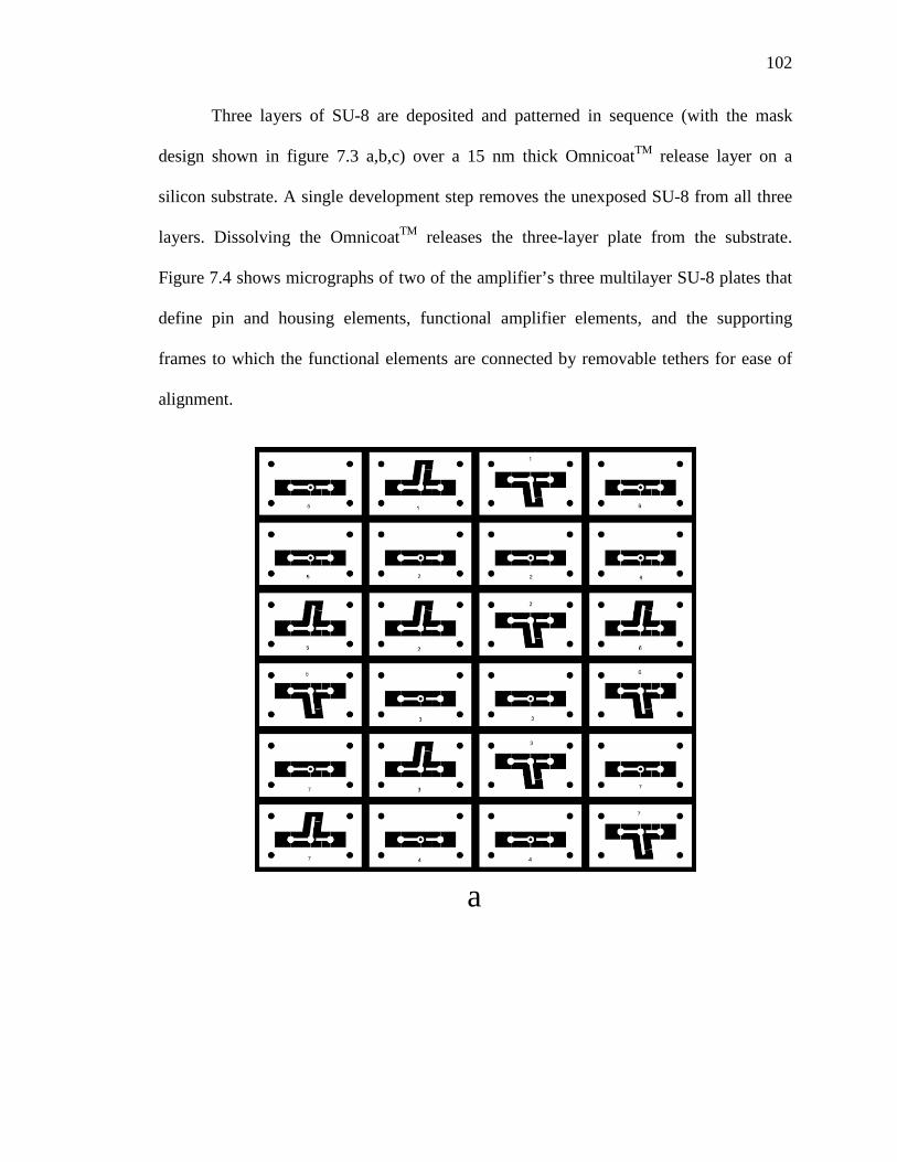
102
Three layers of SU-8 are deposited and patterned in sequence (with the mask
design shown in figure 7.3 a,b,c) over a 15 nm thick OmnicoatTM release layer on a
silicon substrate. A single development step removes the unexposed SU-8 from all three
layers. Dissolving the OmnicoatTM releases the three-layer plate from the substrate.
Figure 7.4 shows micrographs of two of the amplifier’s three multilayer SU-8 plates that
define pin and housing elements, functional amplifier elements, and the supporting
frames to which the functional elements are connected by removable tethers for ease of
alignment.
a
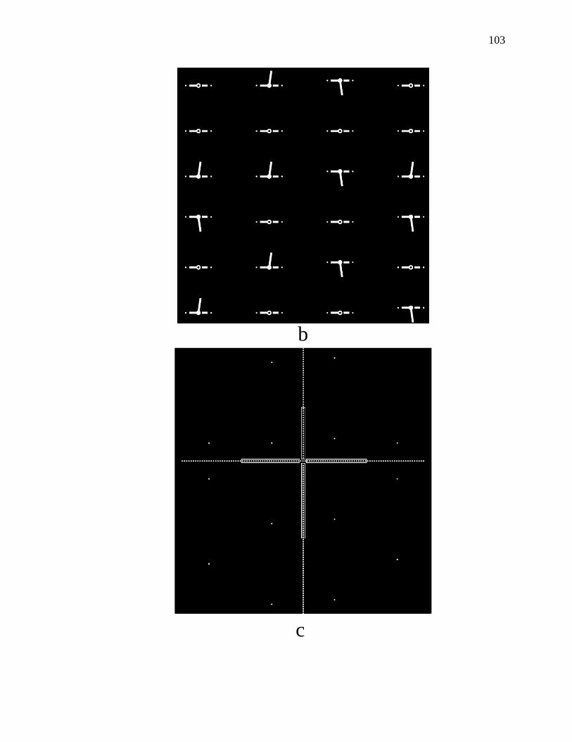
103
b
c
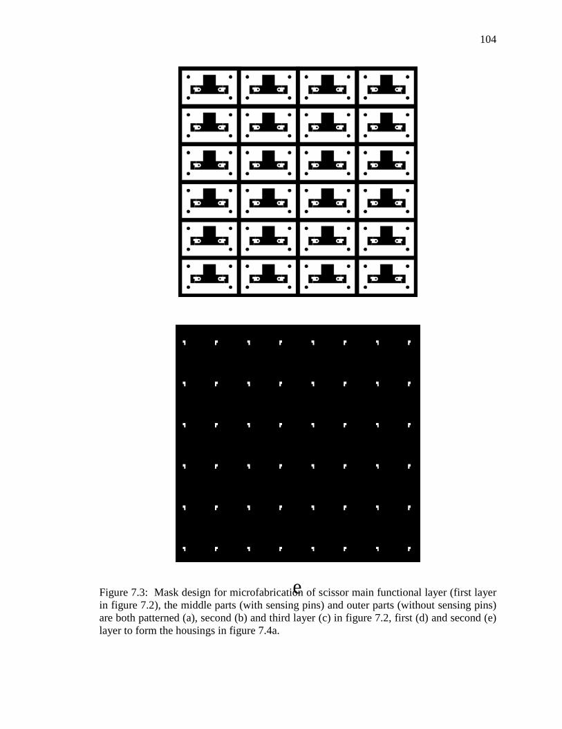
104
Figure 7.3: Mask design for microfabrication of scissor main functional layer (first layer in figure 7.2), the middle parts (with sensing pins) and outer parts (without sensing pins) are both patterned (a), second (b) and third layer (c) in figure 7.2, first (d) and second (e) layer to form the housings in figure 7.4a.
d
e

105
Three multilayer SU-8 plates together form each half of the amplifier structure
(Figure 7.5). In the first half, plates a and c define the linkages. The linkages in plates a
and c are adhered to each other, retaining the one-part central barrel pin (plate c) in its
housing (plate a). The adhesion of plates a and c also captures their two-part outer barrel
pins in the outer housings (plate b, with the mask design shown in figure 7.3 c,d). The
two-part outer pins allow the anchors to rotate without constraint, and the one-part central
pin permits motion and rotation of the sensing interface. The two halves (a-c and d-f) are
adhered to each other to form the complete device, connecting both the linkage/sensing
interface and the anchors that align with the PZT actuator. The thickness of each layer is
set to ensure proper mechanical interfaces among the parts. All pins are fabricated from
SU-8 50; all structural elements (except for the anchors) are fabricated from SU-8 100;
and the anchors are fabricated from SU-8 2150.

106
Figure 7.4: Micrographs of (a) the 2-layer SU-8 “outer housing” structure on its alignment frame and (b) the 3-layer SU-8 “pins and linkages” structure on its frame.

107
Figure 7.5: Exploded view of a micro motion amplifier, in which each functional layer of SU-8 ranges from 100 µm to 300 µm.
Figure 7.6: Schematic diagram of the coarse alignment process showing dowel pins aligning the outer alignment frames and the functional features supported in the centers of the frames.

108
The supporting frames include four holes through which dowel pins are inserted to
provide coarse alignment during assembly (Figure 7.6); figures 7.7a and 7.7b show the
top view and zoomed in view of the laminated frames. A 20-gram mass block as shown
in figure 7.7c provides a pressure during the lamination to ensure robust adhesion
between the layers. The barrel hinges provide fine self-alignment via the pin-housing
clearance. A thin layer of approximately 5 µm thick cyanoacrylate adhesive is applied
manually by a brush to the areas shown in Figure 7.5 (red) to bond the linkages together,
ensuring that the pins remain in their corresponding housings. The two mirror-image sets
of three plates each are included to increase stiffness and symmetry. The tethers that
connect the scissor to the frame are broken after assembly to release the scissor.
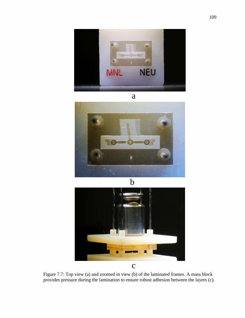
109
Figure 7.7: Top view (a) and zoomed in view (b) of the laminated frames. A mass block provides pressure during the lamination to ensure robust adhesion between the layers (c).
a
b
c

110
Figure 7.8a shows the laminated scissor in its initial position; the recessed design
of its anchors creates end stops that passively align the scissor onto the PZT actuator.
Figures 7.8b and 7.8c show how the unlimited rotation of the barrel hinges permits much
larger deformation angles than are possible for the pivot-hinged architecture of chapter 6.
Figure 7.8d shows a completely-assembled actuator with the hinged scissor self-aligned
on a PZT extensional actuator.
The assembled SU-8 scissors are attached to 5 mm x 2 mm x 0.38 mm (10 mm2
footprint), y-poled PZT actuators to form the final tactile interfaces. Cyanoacrylate
adhesive is applied manually to each scissor’s recessed anchor points before assembly
onto its actuator. The spacing between the anchor attachment points slightly exceeds the
length of PZT actuator, creating an initial angle of about 7-8° between the linkages and
the PZT after scissor attachment, ensuring predictable motion amplification upon PZT
actuation.
The PZT actuators are electrically connected via conductive epoxy to a
lengthwise metal strip electrode (below the PZT) and to a perpendicular metal strip
electrode (above the PZT) as shown in Figure 7.8d. Connections are made at the center of
the device so that the tactile interface is located above the mechanical neutral point
during actuation.

111
Figure 7.8: Photographs of an assembled scissor with three barrel hinges showing (a) alignment of end stops to PZT actuator and (b, c) large rotation angles; (d) photograph of a complete actuator.

112
7.3 Experiments and Results
Barrel hinges with as-designed gaps of 15 µm and 50 µm are fabricated. To
measure the displacement of the actuator’s sensing interface under applied voltage, the
assembled actuator is placed so that its direction of motion is parallel to the viewing
plane of a stereomicroscope. A voltage amplifier (Falco WMA-02) amplifies the square
wave generated by a function generator (BK Precision 4040A) with a frequency of 0.5
Hz; the resulting signal is applied to the PZT actuator. The peak amplitude of the square
wave increases in 10 V steps from 50 V to 170 V. The microscope captures the location
of the sensing interface in its positive actuated position and in its negative actuated
position. For each position, two or three pictures are captured. The displacement of the
sensing interface is the difference between the positive and negative positions, measured
by pixel counting (1 pixel = 0.5 µm). The calibration of the image is calibrated with a
micrometer.
The force output of the actuators is measured by an Instron tensile tester (Instron
5943). The actuators are mounted on a stage so that the sensing interface contacts the
load cell. A 40 mN preload is applied to the sensing interface when null voltage is
applied to mimic a real finger load. Similar to the displacement testing, square wave AC
voltages between 50 V and 170 V are applied, increasing in steps of 10 V, but with a
frequency of 10 Hz. Force is measured by the load cell of the tensile tester.

113
Figure 7.9: Plots of the measured displacement (above) and measured force (below) vs. applied voltage.
Figure 7.9 plots the measured vibrational amplitude vs. voltage and the measured
force vs. voltage for each of the tested devices. The dashed lines represent the
displacement predicted analytically for each geometry for the simplified case of an ideal
microscissor with ideal, zero-clearance pinned hinges. The blue and red dots represent

114
individual measurements.
The maximum measured displacement of 11.5 μm and the maximum measured
force of 10.5 mN for barrel hinged actuators of 15 µm clearance correspond to
displacements per unit actuator area of 1.15 µm/mm2 and and forces per unit actuator
area of 1.05 mN/mm2. These results exceed the vibrational tactile sensing thresholds for
displacement and force of 4 μm and 2 mN as reported in chapter 4.
7.4 Chapter Summary
The process introduced in this chapter offers good robustness and rapid speed of
development because the final structure’s multi-layer architecture is divided among six
much simpler microfabricated elements, reducing attrition losses. The advantages of
simplified microfabrication could in theory be counteracted by the potential for yield loss
during the assembly process. However, the use of a two-stage alignment process (coarse
alignment via dowel pins and fine alignment via the hinges themselves) offers robust
integration of multiple separate layers into a final, complex, three-dimensional
architecture. In addition, the use of an assembly process enables the creation of hinged
structures with smaller clearances than would be permitted by the design rules for SU-8
microfabrication of separated, in-plane features of this thickness. Although the
integration of diverse microstructures has been demonstrated previously, for example in
the context of multifunctional optical, electronic, and MEMS devices (Lapisa, 2011), the
present assembly approach advances the state of the art by leveraging purely low-cost
alignment tools to create mechanical structures with full rotation.
The barrel hinges with two nominal gap clearances of 15 μm and 50 μm are

115
fabricated as described previously. Barrel-hinged devices with 50 μm clearance perform
similarly to the 50 μm clearance devices of chapter 6. However, both the measured force
and the measured displacement of devices with 15 μm clearance exceed those of 50 μm
clearance devices, with up to >18% and >9% increase in displacement and force
respectively as compared with chapter 6. Most significantly, the two-stage passive
alignment of the barrel-hinged approach provides rapid, straightforward manufacture of
complex, out-of-plane MEMS architectures.

116
Chapter 8
CONCLUSION AND FUTURE WORK
In previous chapters, the design, fabrication, and characterization of a series of
tactile actuators were described. This final chapter summarizes the major contributions of
this research and the future work that may be carried out to extend this project.
8.1 Summary of Contributions
• A new motion amplification mechanism enables large displacement and high
force from a limited area of actuator footprint.
The micro scissor motion amplification mechanism was introduced in
chapter 3. It converts and amplifies small in-plane displacements into
larger out-of-plane displacements, offering the possibility for producing
large motion from a limited area for applications like high resolution
tactile displays.
• A set of high performance micro actuators with large displacement and high force
are developed, with potential applications in assistive technology, micropumps,
virtual reality, and private communication.
The high performance micro actuators developed in this thesis
demonstrated their abilities to deliver high force and large displacement at
the small scale. They can be used to provide readily-sensed actuations not
only for tactile displays, but also for virtual reality, etc. Their adjustable

117
frequency ability and performance also enable them to be utilized as the
driving actuator for micropumps.
• Passively self-aligned assembly-based processes are created for rapidly
implementing compact, robust micro hinges with unconstrained rotation, along
with the tactile actuators that employ them.
The self-aligned assembly technologies were introduced in chapter 6 and
chapter 7. The processes offer rapid and precise approaches for micro
structure assembly. These processes can be further developed for
application to a more general microfabrication assembly.
• Human finger perception of tactile actuators based on different actuation
frequencies and vibrational amplitudes is quantitatively evaluated.
Qualitative measurements of humans’ perceptions of tactile actuators
indicate that the actuators are readily sensed, identify the limits of their
sensing, and show agreement with the predictions of the literatures
(William, 1968) regarding human finger pad perception.
• A 28-element tactile display based on these techniques is demonstrated.
In chapter 4, a 28-element tactile display was fabricated. This tactile
display demonstrated simple patterns.
8.2 Suggested Future Work
8.2.1 Minimizing Vibrational Damping
In chapter 4, an issue of co-vibration was introduced. Future work should focus in
part on minimizing vibrational damping at the target pin while retaining appropriate

118
isolation from neighboring pins. Possible solutions include adding springs between each
element’s cells and increase the weight of the substrate.
8.2.2 Self-aligned Assembly for the Laminated Scissors in Chapter 5
Chapter 5 showed the design and fabrication of a set of SU-8 micro structures
laminated on the opposing side of a polyimide tape to form a compact scissor mechanism.
The detailed fabrication process is also introduced in chapter 5. In chapter 6, a process for
temporarily tethering functional SU-8 parts onto a removable alignment frame was
developed. The laminated flexural hinge process of chapter 5 may be improved by using
an alignment frame design to fabricate and assemble the micro scissors of chapter 5 to
provide a better alignment.
Figure 8.1: Proposed mask design for self-aligned laminated scissor structure

119
8.2.3 Investigation of How the Shape and Area of Sensing Pin Affect the Finger Sensory
It was notable in the user testing that the shape of the sensing pin might have an
impact on how people perceive the sensation from the tactile actuators. Spherical,
rectangular and needle shapes can be tested under same voltage and frequency applied to
the actuators.
Figure 8.2: Schematic diagram of micro scissor with alternative sensing pin with larger area of rectangular contacting area.
8.2.4 A New Design Aiming to Double Displacement Per Unit Area
All of the tactile actuators developed in this thesis were based on the model and
concept of scissor motion amplifiers, in which the two ends of a full scissor are anchored
on an extensional PZT actuator. The center of the PZT actuator is fixed, allowing the

120
PZT’s (and the scissor’s) two ends to move closer together or further apart from each
other. One possible advanced architecture would use a half-scissor design as in figure 8.3
instead of a full-scissor design. This design essentially replaces a piezoelectric actuator of
length L with a piezoelectric actuator of length L/2 without reducing the predicted
vertical displacement. In other words, this architecture offers a doubling of displacement
per unit area of the actuator. As shown in figure 8.3, the scissor linkage must be free to
rotate at its pinned anchor joint and free to slide (within constrained limits) at the
scissor’s peak. In the diagram shown here, the anchor joint is implemented as a pivot
hinge as in chapter 6. The effects of friction at the sliding contact must be considered in
assessing whether this design can in practice produce the predicted doubling of
displacement per unit of actuator area as compared with the scissor design in chapter 6.
Figure 8.3: The proposed new design aiming to double the displacement per unit area.

121
8.2.5 A 10 × 10 Tactile Display Array
A 28-element tactile display was demonstrated in this thesis. Although it
successfully showed some initial human testing results, it would be highly useful to
fabricate a 10 x 10 array with the integration of 100 tactile actuators, and in particular
with smaller tactile actuators. The 10 x 10 tactile displays could demonstrate the delivery
and interpretation of more complicated spatial and temporal patterns and rhythms, thus
providing a tool for further usage testing and demonstration. Of the four generations of
tactile actuators shown in this thesis, the most promising version for a 10 x 10
demonstration array is the actuator with 3D printed or photo-patterned SU-8 scissors
because of their suitability for fast prototyping and mass manufacturing.
8.3 Conclusion
In this thesis, new types of actuators employing motion amplification mechanisms
were designed, modeled, implemented, and characterized. The design, fabrication and
characterization of several technology generations of MEMS-enabled, vibrational tactile
actuators were presented. These high performance actuators have potential in applications
like virtual reality sensory feedback, private communications and microrobotics.
Future works lie in the further optimization of the fabrication and assembly for
more ideal structures and for reduced manufacturing complexity. In addition, an
investigation into how variations of the human-machine sensory interface affect the
sensing quality are recommended. Finally, it is recommended that larger tactile displays
comprising greater numbers of tactile elements should be fabricated and tested to

122
characterize their array function and their ability to code information effectively in
combinations of static patterns of vibrations, moving patterns of vibrations, and rhythms.

123
REFERENCES
AxonVR, Seattle, WA http://axonvr.com/blog/what-is-haptics-really-part-2
Bar-Cohen, Y. (2004). Electroactive polymer (EAP) actuators as artificial muscles:
reality, potential, and challenges (Vol. 136). SPIE press.
Bell, D. J., Lu, T. J., Fleck, N. A., & Spearing, S. M. (2005). MEMS actuators and
sensors: observations on their performance and selection for purpose. Journal of
Micromechanics and Microengineering, 15(7), S153.
Bicchi, A., Buss, M., Ernst, M. O., & Peer, A. (2008). The sense of touch and its
rendering. Springer Tracts in Advanced Robotics, 45.
Bliss, J. C., Katcher, M. H., Rogers, C. H., & Shepard, R. P. (1970). Optical-to-tactile
image conversion for the blind. IEEE Transactions on Man-Machine Systems,
11(1), 58-65.
Boldea, I., & Nasar, S. A. (1997, May). Linear electric actuators and generators. In
Electric Machines and Drives Conference Record, 1997. IEEE International (pp.
MA1-1). IEEE.
Cholewiak, R. W., & Collins, A. A. (1995). Vibrotactile pattern discrimination and
communality at several body sites. Attention, Perception, & Psychophysics, 57(5),
724-737.

124
Downar, J., Crawley, A. P., Mikulis, D. J., & Davis, K. D. (2000). A multimodal cortical
network for the detection of changes in the sensory environment. Nature
neuroscience, 3(3), 277-283.
Felder, J., Lee, E., & DeVoe, D. L. (2015). Large vertical displacement electrostatic
zipper microstage actuators. Journal of Microelectromechanical Systems, 24(4),
896-903.
Fett, T., Munz, D., & Thun, G. (1999). Tensile and bending strength of piezoelectric
ceramics. Journal of Materials Science Letters, 18(23), 1899-1902.
Gescheider, G. A., Wright, J. H., & Verrillo, R. T. (2010). Information-processing
channels in the tactile sensory system: A psychophysical and physiological
analysis. Psychology press.
Goldish, L. H., & Taylor, H. E. (1974). The Optacon: A Valuable Device for Blind
Persons. New Outlook for the Blind, 68(2), 49-56.
Goldstein, E. B., & Brockmole, J. (2016). Sensation and perception. Cengage Learning.
Jaffe, B. (2012). Piezoelectric ceramics (Vol. 3). Elsevier.
Jairakrean, S., & Chanthasopeephan, T. (2009, June). Position control of SMA actuator
for 3D tactile display. In Rehabilitation Robotics, 2009. ICORR 2009. IEEE
International Conference on (pp. 234-239). IEEE.
Jia, Z., Li, J., & Chen, C. (2015). Design and evaluation of a thermal tactile display for
colour rendering. International Journal of Advanced Robotic Systems, 12(11), 162.

125
Jiménez, J., Olea, J., Torres, J., Alonso, I., Harder, D., & Fischer, K. (2009). Biography
of louis braille and invention of the braille alphabet. Survey of ophthalmology,
54(1), 142-149.
Johnson, K. O. (2001). The roles and functions of cutaneous mechanoreceptors. Current
opinion in neurobiology, 11(4), 455-461.
Kaczmarek, K. A., Webster, J. G., Bach-y-Rita, P., & Tompkins, W. J. (1991).
Electrotactile and vibrotactile displays for sensory substitution systems. IEEE
Transactions on Biomedical Engineering, 38(1), 1-16.
Kajimoto, H., Kawakami, N., Tachi, S., & Inami, M. (2004). Smarttouch: Electric skin to
touch the untouchable. IEEE computer graphics and applications, 24(1), 36-43.
Kim, Y., Oakley, I., & Ryu, J. (2006, October). Design and psychophysical evaluation of
pneumatic tactile display. In SICE-ICASE, 2006. International Joint Conference
(pp. 1933-1938). IEEE.
Klein, D., Freimuth, H., Monkman, G. J., Egersdörfer, S., Meier, A., Böse, H., ... &
Bruhns, O. T. (2005). Electrorheological tactel elements. Mechatronics, 15(7),
883-897.
Klein, D., Rensink, D., Freimuth, H., Monkman, G. J., Egersdörfer, S., Böse, H., &
Baumann, M. (2004). Modelling the response of a tactile array using
electrorheological fluids. Journal of Physics D: Applied Physics, 37(5), 794.

126
Kotani, H., Takasaki, M., & Mizuno, T. (2007, August). Surface acoustic wave tactile
display using a large size glass transducer. In Mechatronics and Automation, 2007.
ICMA 2007. International Conference on (pp. 198-203). IEEE.
Kron, A., & Schmidt, G. (2003, March). Multi-fingered tactile feedback from virtual and
remote environments. In Haptic Interfaces for Virtual Environment and
Teleoperator Systems, 2003. HAPTICS 2003. Proceedings. 11th Symposium on
(pp. 16-23). IEEE.
Kyung, K. U., Srinivasan, M. A., & Kwon, D. S. (2007, March). Development of
quantitative tactile display device to provide both pin-array-type tactile feedback
and thermal feedback. In EuroHaptics Conference, 2007 and Symposium on
Haptic Interfaces for Virtual Environment and Teleoperator Systems. World
Haptics 2007. Second Joint (pp. 578-579). IEEE.
Lapisa, M., Stemme, G., & Niklaus, F. (2011). Wafer-level heterogeneous integration for
MOEMS, MEMS, and NEMS. IEEE Journal of Selected Topics in Quantum
Electronics, 17(3), 629-644.
Lee, C. H., Jiang, K., & Davies, G. J. (2007). Sidewall roughness characterization and
comparison between silicon and SU-8 microcomponents. Materials
characterization, 58(7), 603-609.
Lee, M. H., & Nicholls, H. R. (1999). Review Article Tactile sensing for mechatronics—
a state of the art survey. Mechatronics, 9(1), 1-31.

127
Liu, Y., Davidson, R. I., Taylor, P. M., Ngu, J. D., & Zarraga, J. M. C. (2005). Single cell
magnetorheological fluid based tactile display. Displays, 26(1), 29-35.
Mansour, N. A., El-Bab, A. M. F., Assal, S. F., & Tabata, O. (2015). Design,
characterization and control of SMA springs-based multi-modal tactile display
device for biomedical applications. Mechatronics, 31, 255-263.
Matsunaga, T., Totsu, K., Esashi, M., & Haga, Y. (2005, May). Tactile display for 2-D
and 3-D shape expression using SMA micro actuators. In Microtechnology in
Medicine and Biology, 2005. 3rd IEEE/EMBS Special Topic Conference on (pp.
88-91). IEEE.
Moheimani, S. R., & Fleming, A. J. (2006). Piezoelectric transducers for vibration
control and damping. Springer Science & Business Media.
Ninomiya, T., Osawa, K., Okayama, Y., Matsumoto, Y., & Miki, N. (2009, March).
MEMS tactile display with hydraulic displacement amplification mechanism. In
Micro Electro Mechanical Systems, 2009. MEMS 2009. IEEE 22nd International
Conference on (pp. 467-470). IEEE.
Park, J. W., Yang, J. H., & Kim, H. (2011, January). A large-deflection high-force micro
electromagnetic hydraulic latex membrane actuator for fluid manipulation in
micro channels. In Micro Electro Mechanical Systems (MEMS), 2011 IEEE 24th
International Conference on (pp. 1209-1212). IEEE.
Pasquero, J. (2003). Stress: A tactile display using lateral skin stretch.

128
Pister, K. S., Judy, M. W., Burgett, S. R., & Fearing, R. S. (1992). Microfabricated
hinges. Sensors and Actuators A: Physical, 33(3), 249-256.
Ronkanen, P. (2008). Current measurement in control and monitoring of piezoelectric
actuators. Tampere University of Technology.
Rowell, J., & Ungar, S. (2003). The world of touch: an international survey of tactile
maps. Part 1: production. British Journal of Visual Impairment, 21(3), 98-104.
Schultz, R. A., Miller, D. C., Kerr, C. S., & Micheli, L. (1984). Mechanoreceptors in
human cruciate ligaments. A histological study. J Bone Joint Surg Am, 66(7),
1072-1076.
Serres, M. (2008). The five senses: A philosophy of mingled bodies. Bloomsbury
Publishing.
Siegelbaum, S. A., & Hudspeth, A. J. (2000). Principles of neural science (Vol. 4, pp.
1227-1246). E. R. Kandel, J. H. Schwartz, & T. M. Jessell (Eds.). New York:
McGraw-hill.
Stack, D. M. (2008). Chapter Thirteen The Salience of Touch and Physical Contact
During Infancy: Unraveling Some of the Mysteries of the Somesthetic Sense.
Blackwell handbook of infant development, 351.
Strong, R. M., & Troxel, D. E. (1970). An electrotactile display. IEEE Transactions on
Man-Machine Systems, 11(1), 72-79.

129
Takasaki, M., Kotani, H., Mizuno, T., & Nara, T. (2005, August). Transparent surface
acoustic wave tactile display. In Intelligent Robots and Systems, 2005.(IROS
2005). 2005 IEEE/RSJ International Conference on (pp. 3354-3359). IEEE.
Tang, H., & Beebe, D. J. (2003). Design and microfabrication of a flexible oral
electrotactile display. Journal Of Microelectromechanical Systems, 12(1), 29-36.
Tani, Y., Shiraishi, Y., Su, H. R., Morita, A., & Suzuki, K. (1995). U.S. Patent No.
5,449,292. Washington, DC: U.S. Patent and Trademark Office.
U.S. Access Board. ABA and ADA Accessibility Guidelines, (2004).
http://www.accessboard.gov/ada-aba/guide.htm
Vallbo, Å. B., & Johansson, R. S. (1984). Properties of cutaneous mechanoreceptors in
the human hand related to touch sensation. Hum Neurobiol, 3(1), 3-14.
Van Boven, R. W., & Johnson, K. O. (1994). The limit of tactile spatial resolution in
humans Grating orientation discrimination at the lip, tongue, and finger.
Neurology, 44(12), 2361-2361.
Vega-Bermudez, F., Johnson, K. O., & Hsiao, S. S. (1991). Human tactile pattern
recognition: active versus passive touch, velocity effects, and patterns of
confusion. Journal of Neurophysiology, 65(3), 531-546.
Verrillo, R. T., Fraioli, A. J., & Smith, R. L. (1969). Sensation magnitude of vibrotactile
stimuli. Attention, Perception, & Psychophysics, 6(6), 366-372.

130
Verrillo, R. T. (1963). Effect of contactor area on the vibrotactile threshold. The Journal
of the Acoustical Society of America, 35(12), 1962-1966.
Verrillo, R. T. (1965). Temporal summation in vibrotactile sensitivity. The Journal of the
Acoustical Society of America, 37(5), 843-846.
William, H. T., Darian-smith, I., & Hans, H. (1968). The Sense of Flutter-Vibration:
Comparison of the Human Capacity With Response Patterns of Mechanoreceptive
Afferents From the Monkey Hand.
World Health Organization, (2014). http://www.who.int/mediacentre/factsheets/fs282/en/
Xie, X., Zaitsev, Y., Velásquez-García, L. F., Teller, S. J., & Livermore, C. (2014).
Scalable, MEMS-enabled, vibrational tactile actuators for high resolution tactile
displays. Journal of Micromechanics and Microengineering, 24(12), 125014.
Xie, X., & Livermore, C. (2015). A high-force, out-of-plane actuator with a MEMS-
enabled microscissor motion amplifier. In Journal of Physics: Conference Series
(Vol. 660, No. 1, p. 012026). IOP Publishing.
Xie, X., & Livermore, C. (2017, January). Passively self-aligned assembly of compact
barrel hinges for high-performance, out-of-plane mems actuators. In Micro
Electro Mechanical Systems (MEMS), 2017 IEEE 30th International Conference
on (pp. 813-816). IEEE.
Xie, X., & Livermore, C. (2016, January). A pivot-hinged, multilayer SU-8 micro motion
amplifier assembled by a self-aligned approach. In Micro Electro Mechanical

131
Systems (MEMS), 2016 IEEE 29th International Conference on (pp. 75-78).
IEEE.
Xie, X., Zaitsev, Y., Velasquez-Garcia, L., Teller, S., & Livermore, C. (2014). Compact,
scalable, high-resolution, MEMS-enabled tactile displays. In Proc. of Solid-State
Sensors, Actuators, and Microsystems Workshop (pp. 127-30).
Yamamoto, A., Cros, B., Hashimoto, H., & Higuchi, T. (2004, April). Control of thermal
tactile display based on prediction of contact temperature. In Robotics and
Automation, 2004. Proceedings. ICRA'04. 2004 IEEE International Conference
on (Vol. 2, pp. 1536-1541). IEEE.
Yang, C., Liu, S., Xie, X., & Livermore, C. (2016). Compact, planar, translational
piezoelectric bimorph actuator with Archimedes’ spiral actuating tethers. Journal
of Micromechanics and Microengineering, 26(12), 124005.
Yoo, J., Yun, S., Lim, S. C., Park, J., Yun, K. S., & Lee, H. K. (2015). Position controlled
pneumatic tactile display for tangential stimulation of a finger pad. Sensors and
Actuators A: Physical, 229, 15-22.
Yosefi, G., Mirzakuchaki, S., Raissi, F., & Afrang, S. (2014). Design and Analysis of a
High Force, Low Voltage and High Flow Rate Electro-Thermal Micropump.
Micromachines, 5(4), 1323-1341.

132
APPENDIX
Appendix A Microfabrication Process for Chapter 4
A-1 Experiment equipment and materials
• Quintel 4000 mask aligner
• Laurell WS-400 lite series spin processor
• VWR Hotplate
• MicroChem SU-8 2150
• MicroChem Omnicoat
• MicroChem Remover PG
• MicroChem SU-8 Developer (PGMEA)
A-2 Fabrication process
1. Dip wafer in acetone for 1 min, then methanol for 1 min, rinse it in DI water for 5
min, dry with N2.
2. Dehydrate the wafer in 125 ºC on hotplate for 5 min and let it cool to room
temperature.
3. Place wafer on spinner, put 5ml of Omnicoat on wafer, 3000 rpm for 30s, bake on
hotplate in 200 ºC for 1 min. Repeat three times and let it cool to room
temperature.

133
4. Pour a chuck of SU-8 2150 on cured Omnicoat, spin at 500 rpm for 30s, ramp to
1000 rpm for 1 min.
5. Prebake the SU-8 2150 in 65 ºC for 20 min, then in 95 ºC for 120 min, let cool to
room temperature.
6. Expose in mask aligner for 200s using mask A-3-1.
7. Postbake the exposed SU-8 2150 in 65 ºC for 20 min, then in 95 ºC for 120 min,
let cool to room temperature.
8. Develop in SU-8 developer for about 1 hour. Dip the wafer in IPA, if milky
appears, put it back into developer till no milky appear when dip in IPA.
9. IPA for 5 min, then rinse in DI water for 5 min.
10. Dip in Remover PG for 2 min to dissolve the Omnicoat release layer.
A-3 Masks
Mask A-3-1

134
Appendix B Microfabrication Process for Chapter 5
B-1 Experiment equipment and materials
• Quintel 4000 mask aligner
• Laurell WS-400 lite series spin processor
• VWR Hotplate
• MicroChem SU-8 2100
• MicroChem Omnicoat
• MicroChem Remover PG
• MicroChem SU-8 Developer (PGMEA)
B-2 Fabrication process
1. Dip wafer in acetone for 1 min, then methanol for 1 min, rinse it in DI water for 5
min, blow dry with N2.
2. Dehydrate the wafer in 125 ºC on hotplate for 5 min and let it cool to room
temperature.
3. Place wafer on spinner, put 5ml of Omnicoat on wafer, 3000 rpm for 30s, bake on
hotplate in 200 ºC for 1 min. Repeat three times and let it cool to room
temperature.
4. Pour a chuck of SU-8 2100 on cured Omnicoat, spin at 500 rpm for 30s, ramp to
1000 rpm for 1 min.
5. Prebake the SU-8 2100 in 65 ºC for 20 min, then in 95 ºC for 120 min, let cool to
room temperature.
6. Expose in mask aligner for 60s using mask B-3-1.

135
7. Postbake the exposed SU-8 2100 in 65 ºC for 20 min, then in 95 ºC for 120 min,
let cool to room temperature.
8. Develop in SU-8 developer for about 1 hour. Dip the wafer in IPA, if milky
appears, put it back into developer till no milky appear when dip in IPA.
9. IPA for 5 min, then rinse in DI water for 5 min.
B-3 Masks
Mask B-3-1

136
Appendix C Microfabrication Process for Chapter 6
C-1 Experiment equipment and materials
• Quintel 4000 mask aligner
• Laurell WS-400 lite series spin processor
• VWR Hotplate
• MicroChem SU-8 50, SU-8 100, SU-8 2150
• MicroChem Omnicoat
• MicroChem Remover PG
• MicroChem SU-8 Developer (PGMEA)
C-2 Fabrication process
C-2-1 Main functional structure with sensing pin
1. Dip wafer in acetone for 1 min, then methanol for 1 min, rinse it in DI water for 5
min, blow dry with N2.
2. Dehydrate the wafer in 125 ºC on hotplate for 5 min and let it cool to room
temperature.
3. Place wafer on spinner, put 5ml of Omnicoat on wafer, 3000 rpm for 30s, bake on
hotplate in 200 ºC for 1 min. Repeat three times and let it cool to room
temperature.
4. Pour a chuck of SU-8 2150 on cured Omnicoat, spin at 500 rpm for 30s, ramp to
1000 rpm for 1 min.

137
5. Prebake the SU-8 2150 in 65 ºC for 20 min, then in 95 ºC for 120 min, let cool to
room temperature.
6. Expose in mask aligner for 150s using mask C-3-1.
7. Postbake the exposed SU-8 2150 in 65 ºC for 20 min, then in 95 ºC for 120 min,
let cool to room temperature.
8. Develop in SU-8 developer for about 1 hour. Dip the wafer in IPA, if milky
appears, put it back into developer till no milky appear when dip in IPA.
9. IPA for 5 min, then rinse in DI water for 5 min, blow dry with N2.
C-2-2 Pivot on cap
1. Dip wafer in acetone for 1 min, then methanol for 1 min, rinse it in DI water for 5
min, blow dry with N2.
2. Dehydrate the wafer in 125 ºC on hotplate for 5 min and let it cool to room
temperature.
3. Place wafer on spinner, put 5ml of Omnicoat on wafer, 3000 rpm for 30s, bake on
hotplate in 200 ºC for 1 min. Repeat three times and let it cool to room
temperature.
4. Pour a chuck of SU-8 100 on cured Omnicoat, spin at 500 rpm for 30s, ramp to
1000 rpm for 1 min.
5. Prebake the SU-8 100 in 65 ºC for 20 min, then in 95 ºC for 120 min, let cool to
room temperature.
6. Expose in mask aligner for 60s using mask C-3-2.
7. Postbake the exposed SU-8 100 in 65 ºC for 20 min, then in 95 ºC for 120 min, let
cool to room temperature.

138
8. Pour a chuck of SU-8 100 on cured SU-8 100, spin at 500 rpm for 30s, ramp to
1000 rpm for 1 min.
9. Prebake the second layer of SU-8 100 in 65 ºC for 20 min, then in 95 ºC for 120
min, let cool to room temperature.
10. Expose in mask aligner for 60s using mask C-3-3.
11. Postbake the second layer of exposed SU-8 100 in 65 ºC for 20 min, then in 95 ºC
for 120 min, let cool to room temperature.
12. Develop in SU-8 developer for about 1 hour. Dip the wafer in IPA, if milky
appears, put it back into developer till no milky appear when dip in IPA.
13. IPA for 5 min, then rinse in DI water for 5 min, blow dry with N2.
C-2-3 Alignment frame
1. Dip wafer in acetone for 1 min, then methanol for 1 min, rinse it in DI water for 5
min, dry with N2.
2. Dehydrate the wafer in 125 ºC on hotplate for 5 min and let it cool to room
temperature.
3. Place wafer on spinner, put 5ml of Omnicoat on wafer, 3000 rpm for 30s, bake on
hotplate in 200 ºC for 1 min. Repeat three times and let it cool to room
temperature.
4. Pour a chuck of SU-8 50 on cured Omnicoat, spin at 500 rpm for 30s, ramp to
1000 rpm for 1 min.
5. Prebake the SU-8 50 in 65 ºC for 20 min, then in 95 ºC for 60 min, let cool to
room temperature.
6. Expose in mask aligner for 30s using mask C-3-4.

139
7. Postbake the exposed SU-8 50 in 65 ºC for 20 min, then in 95 ºC for 60 min, let
cool to room temperature.
8. Develop in SU-8 developer for about 1 hour. Dip the wafer in IPA, if milky
appears, put it back into developer till no milky appear when dip in IPA.
9. IPA for 5 min, then rinse in DI water for 5 min.
10. Dip in Remover PG for 2 min to dissolve the Omnicoat release layer.
C-3 Masks
C-3-1

140
C-3-2
C-3-3

141
C-3-4

142
Appendix D Microfabrication Process for Chapter 7
D-1 Experiment equipment and materials
• Quintel 4000 mask aligner
• Laurell WS-400 lite series spin processor
• VWR Hotplate
• MicroChem SU-8 50, SU-8 100
• MicroChem Omnicoat
• MicroChem Remover PG
• MicroChem SU-8 Developer (PGMEA)
D-2 Fabrication process
D-2-1 Amplifier structure
1. Dip wafer in acetone for 1 min, then methanol for 1 min, rinse it in DI water for 5
min, blow dry with N2.
2. Dehydrate the wafer in 125 ºC on hotplate for 5 min and let it cool to room
temperature.
3. Place wafer on spinner, put 5ml of Omnicoat on wafer, 3000 rpm for 30s, bake on
hotplate in 200 ºC for 1 min. Repeat three times and let it cool to room
temperature.
4. Pour a chuck of SU-8 100 on cured Omnicoat, spin at 500 rpm for 30s, ramp to
1000 rpm for 1 min.

143
5. Prebake the SU-8 100 in 65 ºC for 20 min, then in 95 ºC for 60 min, let cool to
room temperature.
6. Expose in mask aligner for 60s using mask D-3-1.
7. Postbake the exposed SU-8 100 in 65 ºC for 20 min, then in 95 ºC for 60 min, let
cool to room temperature.
8. Pour another chuck of SU-8 100 on first layer SU-8 100, spin at 500 rpm for 30s,
ramp to 1000 rpm for 1 min.
9. Prebake the second layer of SU-8 100 in 65 ºC for 20 min, then in 95 ºC for 60
min, let cool to room temperature.
10. Expose in mask aligner for 60s using mask D-3-2.
11. Postbake the second layer of exposed SU-8 100 in 65 ºC for 20 min, then in 95 ºC
for 60 min, let cool to room temperature.
12. Pour a chuck of SU-8 50 on second layer SU-8 100, spin at 500 rpm for 30s, ramp
to 1000 rpm for 1 min.
13. Prebake the second layer of SU-8 50 in 65 ºC for 20 min, then in 95 ºC for 60 min,
let cool to room temperature.
14. Expose in mask aligner for 60s using mask D-3-3.
15. Postbake the second layer of exposed SU-8 100 in 65 ºC for 20 min, then in 95 ºC
for 60 min, let cool to room temperature.
16. Develop in SU-8 developer for about 2 hours. Dip the wafer in IPA, if milky
appears, put it back into developer till no milky appear when dip in IPA.
17. IPA for 5 min, then rinse in DI water for 5 min, blow dry with N2.
18. Dip in Remover PG for 2 min to dissolve the Omnicoat release layer.

144
D-2-2 Anchors
1. Dip wafer in acetone for 1 min, then methanol for 1 min, rinse it in DI water for 5
min, blow dry with N2.
2. Dehydrate the wafer in 125 ºC on hotplate for 5 min and let it cool to room
temperature.
3. Place wafer on spinner, put 5ml of Omnicoat on wafer, 3000 rpm for 30s, bake on
hotplate in 200 ºC for 1 min. Repeat three times and let it cool to room
temperature.
4. Pour a chuck of SU-8 100 on cured Omnicoat, spin at 500 rpm for 30s, ramp to
1000 rpm for 1 min.
5. Prebake the SU-8 100 in 65 ºC for 20 min, then in 95 ºC for 60 min, let cool to
room temperature.
6. Expose in mask aligner for 60s using mask D-3-4.
7. Postbake the exposed SU-8 100 in 65 ºC for 20 min, then in 95 ºC for 60 min, let
cool to room temperature.
8. Pour another chuck of SU-8 100 on cured SU-8 100, spin at 500 rpm for 30s,
ramp to 1000 rpm for 1 min.
9. Prebake the second layer of SU-8 100 in 65 ºC for 20 min, then in 95 ºC for 60
min, let cool to room temperature.
10. Expose in mask aligner for 60s using mask D-3-5.
11. Postbake the second layer of exposed SU-8 100 in 65 ºC for 20 min, then in 95 ºC
for 60 min, let cool to room temperature.

145
12. Develop in SU-8 developer for about 1.5 hour. Dip the wafer in IPA, if milky
appears, put it back into developer till no milky appear when dip in IPA.
13. IPA for 5 min, then rinse in DI water for 5 min, blow dry with N2.
14. Dip in Remover PG for 2 min to dissolve the Omnicoat release layer.
D-3 Masks
D-3-1

146
D-3-2
D-3-3

147
D-3-4
D-3-5

148
Appendix E Useful Notes in Microfabrication
Though these actuators in this thesis have been successfully demonstrated, some tricky
parts of the experiment should be noticed.
• During the post baking of SU-8, slowly cooling process is desired. A ramp of 10
ºC/hr was used to minimize the residual stress in the cured SU-8.
• When cooling to the room temperature, better to leave the SU-8 overnight before
next step.
• In the step of SU-8 developing, container filled with SU-8 developer should be
placed on a hotplate at 50 ºC to avoid sudden temperature drop when dipping the
SU-8 in. Because SU-8 developer is very easy to evaporate, the temperature of the
liquid in cleanroom is lower than the room temperature.
• Special attention should be paid to the exposure of the SU-8 structures. It is
always better over exposure than under exposure because when the exposure time
is not enough, bottom part of SU-8 layers won’t be cured completely, leading to
SU-8 part failure and poor adhesion between SU-8 and substrate.

149
Appendix F Northeastern University Human Subject Research Protection Approval
Form

150

151

152