high performance distance sensors
TRANSCRIPT

EN
X1TA High Performance Distance Sensors
Operating Instructions
Translation of the Original Operating Instruction Subject to change without notice
Available as PDF version onlyStatus: 06.11.2018www.wenglor.com

2 Index
Index
1. Proper Use 4
2. Safety Precautions 42.1. Safety Precautions 4
2.2. Laser/LED warning 4
3. EU Declaration of Conformity 4
4. Technical Data 54.1. Connecting the Sensors 7
4.2. Housing Dimensions 8
4.3. The Control Panel 8
4.4. Complementary Products (see catalog) 8
5. Mounting Instructions 9
6. Initial Start-Up 96.1. Initial Start-Up 9
6.2. Default Settings 10
7. Functional Overview 117.1. RUN 12
7.2. Pin Function 12
7.3. A1/A2/A3 Switch 12
7.4. A3 Error F/A3 Input 15
7.4.1. A3 Error 15
7.4.2. A3 Input 15
7.5. A1 Analog/Analog 16
7.6. Offset 17
7.7. Measuring rate 19
7.8. Laser 19
7.9. Read-Out 20
7.10. Interface (does apply to X1TA101MHT88) 21
7.11. Display 24
7.12. Language 24
7.13. Info 24
7.14. Reset 24
7.15. Password 25
3High Performance Distance Sensors
8. More Settings and Queries via the RS-232 Interface 278.1. Remote Control via a Terminal Program 28
8.2. Remote Control with Interface Commands 29
9. Maintenance Instructions 29
10. Proper Disposal 29

4 Proper Use
1. Proper UseThis wenglor product has to be used according to the following functional principle:
High Performance Distance SensorsThis group brings together the most powerful sensors for distance measurement, which work in reflex mode ac-
cording to different principles. High performance distance sensors are particularly fast and precise, and dem-
onstrate their high efficiency over large working ranges. They are ideally suited for demanding applications.
Even black and shiny objects are reliably detected. Ethernet technology is integrated into selected sensors.
2. Safety Precautions2.1. Safety Precautions
• This operating instruction is part of the product and must be kept during its entire service life.
• Read this operating instruction carefully before using the product.
• Installation, start-up and maintenance of this product should only be carried out by trained personnel.
• Tampering with or modifying the product is not permissible.
• Protect the product against contamination during start-up.
• Not a safety component in accordance with the EU Machinery Directive.
2.2. Laser/LED warning
LASER CLASS 1EN60825-1
2007
Class Laser 1 (EN 60825-1)Observe all applicable standards and safety precautions.
3. EU Declaration of ConformityThe EU declaration of conformity can be found on our website at www.wenglor.com in download area.
RoHS
UL Certified only in combination with the following wenglor connection cables: S23, S35, S88.

5High Performance Distance Sensors
4. Technical Data
Optical Data X1TA101MHT88 X1TA101MHV80 X1TA100QXT3Working range 0,2…100,2 m 0,2…100,2 m 0,1…10,2 mWorking range analog 0,2…100,2 m 0,2…100,2 m 0,2…10,2 mMeasuring range 100 m 100 m 10 mReference reflector/reflector sheet 4 × RQ100BA 4 × RQ100BA RQ100BALinearity 0,05 % 0,05 % 0,5 %Switching hysteresis 13…50 mm 13…50 mm 3…20 mmLight Source Laser (rot) Laser (rot) Laser (rot)Wave Length 660 nm 660 nm 660 nmService life (amb. temp. = 25 °C) 100000 h 100000 h 100000 hLaser Protection Class (EN60825-1) 1 1 1Beam Divergence < 2 mrad < 2 mrad < 2 mradElectrical DataSupply Voltage* 18…30 V DC 18…30 V DC 18…30 V DCCurrent Consumption (operating voltage = 24 V) < 100 mA < 100 mA < 100 mASwitching Frequency 50 Hz 50 Hz 50 HzResponse Time 10…200 ms 10…200 ms 10…200 msMeasuring rate 1…100/s 1…100/s 1…100/sTemperature Drift <0,5 mm/k <0,5 mm/k <0,2 mm/k**Temperature Range –25…60 °C –25…60 °C –25…60 °CNumber of switching outputs, configurable as PNP, NPN or push-pull
2 3 2
Switching Output Voltage Drop < 2,5 V < 2,5 V < 2,5 VSwitching Output Switching Current 200 mA 200 mA 200 mAError Output yes yes yesError Output Switching Current 200 mA 200 mA 200 mAAnalog Output 0…10 V 0…10 V 0…10 VCurrent Load Voltage Output <1 mA <1 mA <1 mAAnalog Output 4…20 mA 4…20 mA 4…20 mACurrent Output Load Resistance <500 W <500 W <500 WShort Circuit Protection yes yes yesReverse Polarity Protection yes yes yesOverload Protection yes yes yesInterface RS-232 – –Configuration 8 N 1 – –Resolution 4…20 mm 4…20 mm 2…6 mmMechanical DataAdjustment Teach-In Teach-In Teach-InHousing Plastic Plastic PlasticProtection IP68 IP68 IP68Connection M12 × 1 M12 × 1 M12 × 1Protection Class III III IIIFDA Accession Number 0920382-000
* Supply voltage residual ripple may not exceed 10 % (within the specified voltage range).**Temperature Drift: 0,4 mm/k at ambient temperature < –10 °C and > 50 °C

6 Technical Data
Measuring Range:The Sensors’ measuring range is determined by object remission and the size of the reflector.
Type of Reflector Mounting Distance
X1TA101 X1TA100
RQ100BA 5...100 m*
0,1...10 m0,2...10 m
RF505 0,2...40 m* 0,1...10 mRF508 0,2...40 m* 0,1...10 mRF258 0,2...40 m** 0,1...10 mZRAF07K01 0,2...40 m 0,1...10 mZRAF08K01 0,2...40 m 0,1...10 mZRDF03K01 0,2...40 m 0...10 m
ZRDF10K01 0,2...100 m*
0...10 m0,2...40 m
* when using 4 reflectors/reflex foils** when using 2 reflectors/reflex foils
In order that the Sensor functions properly, the whole light spot of the Sensor has to hit the reflector. Please
chose the suitable reflector!
Light Spot DiameterWorking Distance 0 10 m 40 m 100 mLight Spot Diameter X1TA 5 mm < 20 mm < 80 mm < 200 mm
Dependence of Hysteresis and Resolution on the Measuring rate on white (90 % Remission)
X1TA101 X1TA100Selected sampling rate in Hz
Default setting for min. hysteresis in mm
Resolution in mm
Default setting for min. hysteresis in mm
Resolution in mm
100 40 20 20 650 35 14 15 520 30 12 10 410 25 10 8 45 20 8 6 32 15 6 4 31 13 4 3 2

7High Performance Distance Sensors
4.1. Connecting the Sensors X1TA101MHV80 X1TA101MHT88 X1TA100QXT3
514 516
Switching laser light off via pin connection:If the “La” pin is open or connected to negative, the laser is on.
If positive voltage is applied, the laser is off.
Connecting Cables M12 × 1, 8-pin Connecting Cables M12 × 1, 8-pin
S88-10MPUR
S88-20MPUR
S88W-2MPUR
S88W-10MPUR
S88W-20MPUR
S17 S80-2M
S80-5M
S80-10M
S80W-2M
S80W-5M
S80W-10M
S01
Connecting Cables M12 × 1, 4-pin Connecting Cables M12 × 1, 4-pin
S29-2M
S29-5M
S29-10M
S29-2MPUR
S29-5MPUR
S02S23-2M
S23-5M
S23-10M
S23-2MPUR
S23-5MPUR
S02
Legend
Wire Colors according to DIN IEC 757
Platinum measuring resistornot connectedTest InputTest Input invertedTrigger InputAnalog OutputGround for the Analog OutputBlock DischargeValve OutputValve Control Output +Valve Control Output 0 VSynchronizationReceiver-LineEmitter-LineGroundingSwitching Distance ReductionEthernet Receive PathEthernet Send PathInterfaces-Bus A(+)/B(–)Emitted Light disengageableMagnet activationInput confirmationContactor MonitoringEncoder A/A (TTL)Encoder B/B (TTL)
BlackBrownRedOrangeYellowGreenBlueVioletGreyWhitePinkGreen/Yellow
Supply Voltage +Supply Voltage 0 VSupply Voltage (AC Voltage)Switching Output (NO)Switching Output (NC)Contamination/Error Output (NO)Contamination/Error Output (NC)Input (analog or digital)Teach InputTime Delay (activation)ShieldingInterface Receive PathInterface Send PathReadyGroundClockOutput/Input programmable
Power over EthernetSafety InputSafety OutputSignal OutputEthernet Gigabit bidirect. data line (A-D) Encoder 0-pulse 0-0 (TTL)
Encoder AEncoder BDigital output MINDigital output MAXDigital output OKSynchronization InSynchronization OUTBrightness outputMaintenancereserved
PT

8 Technical Data
4.2. Housing Dimensions
Screw M4 = 0,5 Nm
4.3. The Control Panel
Display
Control key
4.4. Complementary Products (see catalog)
wenglor offers Connection Technology for field wiring.
Suitable Mounting Technology No. 340
Suitable Connection Technology No.2 80 88
S02 S01 S17
Analog Evaluation Unit AW02Reflector, Reflector FoilProtection Housing Set ZST-NN-02

9High Performance Distance Sensors
5. Mounting InstructionsAll applicable electrical and mechanical regulations, standards and safety precautions must be adhered to
when installing and operating the Sensor. The Sensor must be protected against mechanical influences. Install
the device such that its installation position cannot be inadvertently changed. The wenglor mounting system is
recommended for installing the Sensor. Additionally a suiting reflector or reflex foil has to be mounted.
6. Initial Start-Up6.1. Initial Start-Up
Connect the Sensor to supply power (18 to 30 V DC). The display view appears.
The Sensor is ready for operation after 2 seconds. The following table provides an overview of typical, addi-
tional deviations during the warm-up phase.
Time (min.) 0 1 2 5 10 15Deviation (mm) ±10 ±7 ±6 ±2 ±1 0
Switch to the configuration menu by pressing any key.
Note:If no settings are adjusted in the configuration menu for a period of 30 s, the Sensor is automatically returned to
the read-out view. The Sensor accesses the last used menu view when a key is once again activated.
If a setting is adjusted, it becomes active when the configuration menu is exited.
The keys are used for navigation, and for configuring settings.

10 Initial Start-Up
Important: Do not use any sharp objects to press the keys when configuring settings, because they might otherwise be damaged.
Navigation up.
Navigation down.
Acknowledge the selected menu item (arrow points towards the display).
Accept the selected setting, exit the menu (arrow points away from the display).
6.2. Default Settings
X1TA100QXT3 X1TA101MHxxx
Pin FunctionA1: Switching output A1: Switching output
A2*: Switching outputA3: Switching output A3: Error output
Outputs
Teach Mode Object ObjectSwitching threshold 1000 mm 1000 mmHysteresis 20 mm 20 mmWindow Size 50 mm 50 mmPNP/NPN PNP PNPNO/NC NO NOON Delay 0 ms 0 msOFF Delay 0 ms 0 msImpulse 0 ms 0 ms
Error OutputPNP/NPN PNP PNPNO/NC NC NO
A3 Input invers
AnalogU/I U U0 V 200 mm 200 mm10 V 10200 mm 100200 mm
Offset Specification Offset 0 mm 0 mmMeasure Rate 100 Hz 20 HzLaser OnRun Mode Display Mode Distance Distance
Interface
Mode Comm CommBaud Rate 38400 38400ASCII binary binary Interval 100 ms 100 msMask 1 1
Display Intensity Screensaver ScreensaverLanguage German
PasswordEnable Off OffEnter 0 0
Does apply to X1TA101MHV80

11High Performance Distance Sensors
7. Functional Overview
ModeBaudrateASCIITA/TIntervalMask
EnableEnterChangeLock
100 Hz50 Hz20 Hz10 Hz5 Hz2 Hz1 Hz
Sensor typeSensor version
MirrorIntensity
Disp ModeRun
ONOFF
A1A3
Offset
English Deutsch Français
ApplyPresetChange
Mode U/ITeachat 0 Vat 10 V
Measure Rate
A3 Switch/Error/Input
Analog
A1 Switch/Analog
A2 Switch
Run
Pin Function
Laser
Run Mode
Interface
Display
Language
Info
Reset
Password
Mode U/ITeachat 0 Vat 10 V
NPN/PNPNO/NC
not inversinvers
Analog Output
Switching Output
Error Output
Input
Switching Output
T ObjectT BackgroundT WindowPotiHysteresis/Window SizeNPN/PNPNO/NCON DelayOFF DelayImpulsExtern T

12 Functional Overview
7.1. RUNThe Sensor can be switched to the display mode by pressing the key.
7.2. Pin FunctionThe Pin Function serves to determine the function of the pins A1 or A3. The pins can each take on different
functions.
Designation Function Key designationA1 Configuration of Pin A1
(does apply to X1TA100QXT3)By pressing the buttons and Pin A1 can be configured as a switching output or analog output.
A3 Configuration of Pin A3
By pressing the button and Pin A3 can be configured as:¡ a switching output ¡ an input for application of the offset¡ an error output ¡ a Teach-Input for A1¡ an input for switching on/off ¡ a Teach-Input for A2 (if A2 available) the transmitted light.
The adjusted function of the pins is displayed figuratively in the menu “Run Mode”:
�� �� Teach-Input A3 for A1 or A2A1 A2 A3 Switch outputAN Analog outputIN InputF Error output
7.3. A1/A2/A3 SwitchBasic settings for the individual switching outputs are selected in the A1/A2/A3 Switch menu.
Designation Function Key designation
T Object Object Teach-In T
Distance to the object is taught in by pressingthe T key:• Align the spot to the object.• Briefly press the T key. Switching distance to the object is set.• If necessary, readjust the switching distancewith the help of the Potentiometer menu item.
* X1TA: (2
Hysterese) + 20 mm
Sensor
Object
*
HysteresisMaking point
Breaking pointBackgrounde. g. conveyor belt

13High Performance Distance Sensors
Designation Function Key designationT Background Background-Teach-In T
Distance to the background is taught in by pressing the T key, so that the background can be suppressed:
• Align the spot to the background
(e.g. conveyor belt).
• Briefly press the T key.Ú The background is suppressed.
* X1TA: ( 2Hysterese) + 20 mm
*
Sensor
HysteresisMaking point
Breaking point
Backgrounde. g. conveyor belt
Object
T Window Teach-In a tolerance window T
A window tolerance is taught in by pressing the T key:• Align the spot to the object.• Briefly press the T key. Ú A tolerance window is set up around the measured distance. The window width value is adjustable (see below). The default value is 50 mm. If the measuring distance lies within the window width, the Sensor is activated.
When the window is taught in, the lower (L) and upper (H) switching points are displayed alternately in line 3.
Sensor
Object
HysteresisBreaking point
Making point
HysteresisMaking point
Breaking point
Window Width
Poti Readjusting the switching distance + –
The switching distance can be readjusted by pressing the + or the – key.
Hysteresis Adjusting switching hysteresis + –
The hysteresis value is adjusted by pressing the + or the – key.Minimum value: depends upon the Measuring rate (see table page 5).
Window Size. Setting the desired window width + –
(Can only be adjusted after Teach Window).The width (10 mm…1000 mm) of the tolerance window is selected by pressing the + or the – key. The default value is 50 mm.

14 Functional Overview
Designation Function Key designation
NPN/PNP Configuring the outputs P N
The output is preset to PNP. Pressing the N key sets the output to push-pull. Pressing the N key again sets the output to NPN. The respective circuit diagram indicates how the output is set:PNP Push-pull NPN
NO/NC Configuring the outputs NO NC
Outputs can be set up as normally open or normally closed by pressing the NO or the NC key. The respective circuit diagram is displayed.
ON Delay Adjusting ON Delay + -
ON Delay can be set to a value within a range of 0 to 10.000 ms by pressing the + or the – key.
������
��������
������
OFF Delay Adjusting OFF Delay + –
Off-delay is adjusted by pressing the + or the – key. Off-delay is disabled if a impulse duration has already been selected. If this is the case, Impulse! appears at the control panel.
Object
OFF Delay
Output
Impulse Adjusting the impulse duration + –
Impulse duration defines how long the output signal remains in the activated state. Impulse duration can be set to a value within a range of 0 to 10.000 ms by pressing the + or the – key. After the selected impulse duration has elapsed, the output signal is returned to the deactivated state.
������
��������
����������������� �����
���������� ����� Function can be combined with ON-delay.
Extern T External Teach
By pressing the button can be selected, if an ”Object Teach-In”, a “Background Teach-In”, or “Teach-In of a tolerance window” is executed at the External Teach-In.

15High Performance Distance Sensors
7.4. A3 Error F/A3 Input
7.4.1. A3 ErrorThe error output is activated if no light signal is returned to the Sensor.
Designation Function Key designationNPN/PNP Output configuration P „ N
The error output is set to PNP, push-pull or NPN by pressing the P or the N key. The respective circuit diagram is displayed.NO/NC Output configuration NO „ NC
The error output is set up as normally open or normally closed by pressing the NO or the NC key. The respective circuit diagram is displayed.
7.4.2. A3 InputIf Pin “A3” is used as input “Emitted light disengageable” or as input “Offset”, the input can be set as an inverted
or non-inverted input.
Designation Function Key designation
Not invers Usage as non-inverted input
Normally, the input is at supply voltage “0“. The functionality of the input is triggered upon applying a voltage > 7 V.
invers Usage as inverted input
The input is normally at a voltage of > 7 V. The functionality of the input is triggered upon applying a voltage < 7 V.

16 Functional Overview
7.5. A1 Analog/Analog
The measuring range for the analog output can be feely selected within the specified working range with rising
of falling characteristic curve.
The adjusted measuring range must have a value of at least 2 % of the total measuring range.
�����������������������
�����������������������
��������������������������
����������������������������
Designation Function Key designation
Mode U/I Analog output as current or voltage output U I
The analog output can be set up as either a current or a voltage output by pressing the U or the I key. The corresponding symbol is displayed.
Teach Teach in the distances which correspond to the upper and lower voltage values
10 V resp.
20 mA
0 V resp. 4 mA
The momentary actual distance is assigned to a voltage value of 10 V or a current value of 20 mA by pressing the 10 V or the 20 mA key.The momentary actual distance is assigned to a voltage value of 0 V or a current value of 4 mA by pressing the 0 V or the 4 mA key.If necessary, the assigned distances can be readjusted with the help of menu items At 0 V or at 10 V.
at 0 V Distance at 0 V + –The distance assigned to either 0 V or 4 mA is adjusted by pressing the + or the – key.
at 10 V Distance at 10 V + –The distance assigned to either 10 V or 20 mA is adjusted by pressing the + or the – key.
17High Performance Distance Sensors
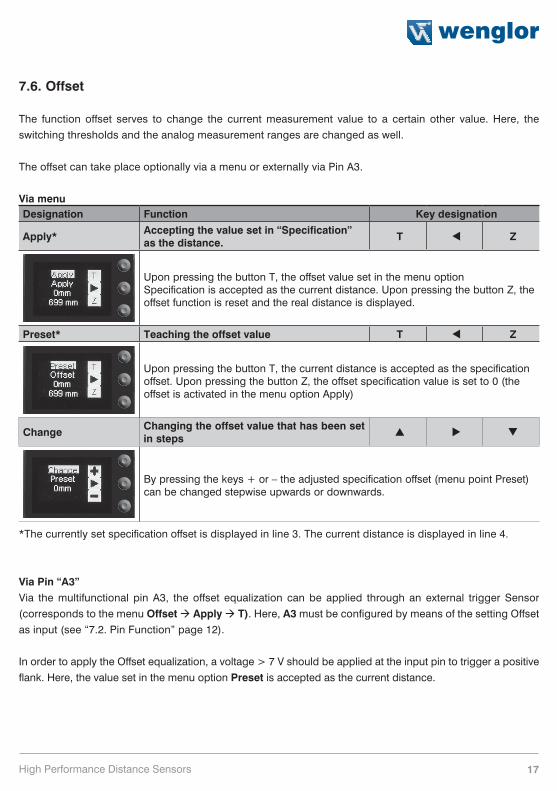
7.6. Offset
The function offset serves to change the current measurement value to a certain other value. Here, the
switching thresholds and the analog measurement ranges are changed as well.
The offset can take place optionally via a menu or externally via Pin A3.
Via menuDesignation Function Key designation
Apply* Accepting the value set in “Specification” as the distance. T Z
Upon pressing the button T, the offset value set in the menu option Specification is accepted as the current distance. Upon pressing the button Z, the offset function is reset and the real distance is displayed.
Preset* Teaching the offset value T Z
Upon pressing the button T, the current distance is accepted as the specification offset. Upon pressing the button Z, the offset specification value is set to 0 (the offset is activated in the menu option Apply)
Change Changing the offset value that has been set in steps
By pressing the keys + or – the adjusted specification offset (menu point Preset) can be changed stepwise upwards or downwards.
*The currently set specification offset is displayed in line 3. The current distance is displayed in line 4.
Via Pin “A3”Via the multifunctional pin A3, the offset equalization can be applied through an external trigger Sensor
(corresponds to the menu Offset à Apply à T). Here, A3 must be configured by means of the setting Offset
as input (see “7.2. Pin Function” page 12).
In order to apply the Offset equalization, a voltage > 7 V should be applied at the input pin to trigger a positive
flank. Here, the value set in the menu option Preset is accepted as the current distance.

18 Functional Overview
Without Offset equalization:In the diagram, the Sensor measures a distance of 5000 mm.
The switching point is located 2000 mm distant, at 7000 mm.
5000 mm 7000 mm
Switching Point
[Distance measured witha meter ruler(mm)]
With application of the offset equalization: Specification offset: 0 mmIn the diagram, the Sensor measures a distance of 5000 mm. The switching point is located 2000 mm distant,
at 7000 mm. After application of the offset equalization, from the distance 5000 mm the distance becomes 0
mm. The switching distance thus gets displaced by 7000 mm to the actual 12000 mm.
5000 mm 12000 mm
Switching Point
[Distance measured witha meter ruler (mm)]
0 mm
Switching Distance: 7000 mm
Application of the offset equalization
Application of the offset equalization: Specification offset: 3000 mmIn the diagram, the Sensor measures a distance of 5000 mm. The switching point is located 2000 mm distant,
at 7000 mm. After application of the offset equalization, from the distance 5000 mm the distance becomes 3000
mm. The switching distance thus gets displaced by 4000 mm to the actual 9000 mm.
5000 mm 9000 mm [Distance measured witha meter ruler (mm)]
3000 mm
Switching distance set: 7000 mm
Application of the offset equalization
3000 mm 4000 mm

19High Performance Distance Sensors
Example of application: A X1TA101MHV80 is used in a high rack warehouse with varying ambient temperatures. To eliminate the
temperature drift, a reference path of 1000 mm is specified to the Sensor as the specification offset. Through
an external trigger Sensor, the specification offset is applied and given to the Sensor as the current distance.
This ensures that the distance tallies with the value of the reference route with every trigger signal and thus, the
varying ambient temperature has no influence on the measurement values of the Sensor.
Movement path of sensor
Reference path1000 mm
Trigger sensor:Switch output, sensor onPIN A3/V of the LLZ-sensor
High rack stores
7.7. Measuring rateReducing the Measuring rate improves resolution and reduces minimum selectable switching hysteresis.
The respective minimum and maximum values are in the table on page 5.
Designation Function Key designation100 Hz
Measuring rate value
50 Hz20 Hz10 Hz5 Hz2 Hz1 HzThe Measuring rate which is best suited for the respective application can be selected from the pre-defined values by pressing the or the key.
7.8. LaserTransmitted light can be either deactivated or activated with the help of the Laser menu.
Designation Function Key designationON Switch transmitted light on
OFF Switch transmitted light offTransmitted light is deactivated or activated by pressing the or the key.
For the products X1TA101MHT88 the laser light can be switched off via pin 5, by connecting pin 5 to 24 V.
If Pin 5 has already been set as an RS-232 interface, the laser diode can be switched off with an interface
command, in the menu or via the A3 input (see “7.2. Pin Function”/”7.4.2. A3 Input”).
In case of the X1TA101MHV80 the laser diode can be switched off via pin 8, by connecting pin 8 to 24 V.

20 Functional Overview
7.9. Read-Out
Which data will be read out to the display as measurement results are selected in the Read-Out menu.
Designation Function Key designationDispMode Select display characteristics
What will appear at the monitor during display mode operation is selected by pressing the or key:
Distance: The states of the individual outputs appear at the display.
Measured analog voltage
Distance to the object
Output configuration/selected delays
Status of the switch outputs of the error output or analog output (if used as analog output: the higher the analog value, the brighter the status display)
Analog: The analog output value appears at the display.
Output configuration/selected delays
Analog output value (U/I)
Measured analog voltage
Distance to the object
Run Switch to the read-out view
The device is switched to the display mode by pressing the key.

21High Performance Distance Sensors
7.10. Interface (does apply to X1TA101MHT88)
The basic settings for the interface are entered to the Interface menu.
Designation Function Key designationMode Basic interface settings
One of the function types, namely Menu, Comm (default setting) or Continuous, is selected by pressing the or key.Menu: The Sensor can be addressed with the help of a terminal program. A menu is generated automatically in the terminal program (see chapter 8.1).Comm: The Sensor can be addressed by means of interface commands (see chapter 8.2).Continuous: The Sensor reads out selected information at a defined interval.
Baud rate Set the baud rate
The interface can be set to one of three baud rates by pressing the or key: 9600, 38.400 (default setting) or 115.200 Baud. 9600 Baud, 38.400 Baud (default setting) or 115.200 Baud.
The individual output values are explained in the following pages.
Continuous transmission: If continuous transmission is used, the values selected from the table shown below are transmitted via the interface at a defined interval.
ASCII Selection of the output format for continuous transmission
Selection is made between the two output formats, ASCII or binary (default setting), by pressing the or the key.
TA/T Selection of the interface protocol
Switching between the old and new interface protocols (X1TA and XT respectively) is possible by pressing the or the key.
Interval Selection of the transmission interval for continuous transmission + –
The length of the interval specifies how frequently data will be transmitted via the interface.The interval can be set within a range of 10 to 10.000 ms by pressing the + or the – key.
[Data]
[Interval]
Interval
Mask Selection of the desired output values for continuous transmission + –
The selected mask specifies which information will be read out to the interface during continuous transmission.Selection can be made from masks 1 through 31 by pressing the + or – key.
22 Functional Overview
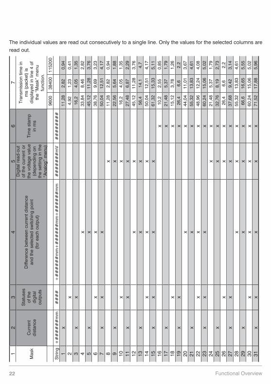
The individual values are read out consecutively to a single line. Only the values for the selected columns are
read out.
12
34
56
7
Mas
kC
urre
nt
dist
ance
Sta
tuse
s of
the
digi
tal
outp
uts
Diff
eren
ce b
etw
een
curr
ent d
ista
nce
and
the
sele
cted
sw
itchi
ng p
oint
(f
or e
ach
outp
ut)
Dig
ital r
ead-
out
of th
e cu
rren
t or
the
volta
ge v
alue
(d
epen
ding
on
the
setti
ng in
the
“Ana
log”
men
u)
Tim
e st
amp
in m
s
Tran
smis
sion
tim
e in
m
s (p
acke
t) is
di
spla
yed
in li
ne 4
of
the
“Mas
k” m
enu
func
tion.
9600
3840
011
5200
Str
ing
+#
##
##
#m
m#
##
#+
##
##
##
mm
+#
##
##
#m
m+
##
##
##
mm
##
##
##
#m
V#
##
##
##
#1
x11
,28
2,82
0,94
2x
4,92
1,23
0,41
3x
x16
,24,
051,
354
x33
,84
8,46
2,82
5x
x45
,12
11,2
83,
766
xx
38,7
69,
693,
237
xx
x50
,04
12,5
14,
178
x11
,28
2,82
0,94
9x
x22
,56
5,64
1,88
10x
x16
,24,
051,
3511
xx
x27
,48
6,87
2,29
12x
x45
,12
11,2
83,
7613
xx
x56
,414
,14,
714
xx
x50
,04
12,5
14,
1715
xx
xx
61,3
215
,33
5,11
16x
10,2
2,55
0,85
17x
x21
,48
5,37
1,79
18x
x15
,12
3,78
1,26
19x
xx
26,4
6,6
2,2
20x
x44
,04
11,0
13,
6721
xx
x55
,32
13,8
34,
6122
xx
x48
,96
12,2
44,
0823
xx
xx
60,2
415
,06
5,02
24x
x21
,48
5,37
1,79
25x
xx
32,7
68,
192,
7326
xx
x26
,46,
62,
227
xx
xx
37,6
89,
423,
1428
xx
x55
,32
13,8
34,
6129
xx
xx
66,6
16,6
55,
5530
xx
xx
60,2
415
,06
5,02
31x
xx
xx
71,5
217
,88
5,96

23High Performance Distance Sensors
Explanation of the individual output values:
Column 2: current distance: read-out of the respective current measuring distance in mm
Column 3: statuses of the digital outputs:
0: not switched
1: switched
# # # #
F A3 A2 A1
Example: 1001 à error output and output 1 switched.
Column 4: difference between current distance and the selected switching point (for each output)
Example:
wen
glor Output 1: switching threshold at 2800 mm
Output 2: switching threshold at 1500 mm
Output to interface:Output 1: –000800Output 2: +000500
Obj
ect 2000 mm
Column 5: digital read-out of the current or the voltage value in mV
(depending on the setting in the “Analog” menu)
Column 6: time stamp
Example:
Time Stamp Measuring Distance00001024 1805 mm00001066 1810 mm99999999 2068 mm00000000 2068 mm
By outputting the time-stamp, the individual measurement distances can be assigned to a relative time without
taking into consideration the processing speed of the computer.
Time stamp: D 1 ≙ 500 µs

24 Functional Overview
7.11. Display
The display can be rotated and brightness can be adjusted with the help of the Display menu.
Designation Function Key designationRotated The display is rotated 180°.
The display is rotated 180° by pressing the key. The display can be returned to its original position by pressing the same key once again.
Intensity Adjusting display intensity
After pressing the or key, the menu appears immediately with the selected intensity (min., normal or max). By selecting the energy saving mode the display switches off after one minute without activating a key. It switches on automatically, when activating a key again.Note: If none of the keys are activated for a given period of time, the display is switched to the energy
saving mode and the intensity is reduced. The display is returned to the selected intensity as soon as any key is activated.
7.12. Language
The desired menu language can be selected in the Language menu.
Designation Function Key designationDeutsch Default language English Menu language Francais Menu language The desired language is selected by pressing the or key. The desired language appears in the menus as soon as it has been selected.
7.13. Info
The following information regarding the Sensor is displayed in the Info menu:
• Sensor type
• Software version
• Serial number
7.14. Reset
Sensor settings can be returned to their default values with the help of the Reset menu. Default settings are
listed in section 6.2.
Designation Function Key designationReset Press <R> to reset R
All of the selected Sensor settings are returned to their default values by pressing the R key.

25High Performance Distance Sensors
7.15. Password
Password settings can be entered in the password menu with the following four submenus.
Designation Function Key designationEnable Switch Password Function On or Off
The Enable menu is accessed by pressing the key, where you can activate or deactivate the password function by selecting Off or On. After interruption of the power supply, the operation of the Sensor is locked. Immediate blockage of the operation can be done in the sub-menu “Lock“.
Enter Password Entry for Enabling the Sensor
The Enter submenu is accessed by pressing the key, where you can enter the password in order to enable the Sensor.
The desired password is entered by means of the + or – key. Press and hold the + or – key in order to scroll quickly through the numbers. Entry is acknowledged by pressing the key.The password is set to 0 upon shipment from the factory.
Change Change the Password
The Change submenu is accessed by pressing the key, where you can change the password.
The desired password is selected with the + or – key, and is acknowledged with the key. Press and hold the + or – key in order to scroll quickly through the numbers.
Lock Lock the Sensor
The Sensor can be disabled with the help of this function, without interrupting supply power.The Sensor is disabled and switched automatically to the password entry mode after pressing the key.
A password must be entered in order to continue using the Sensor.

26 Functional Overview
Notes regarding password functions:If the password function has been activated, the password must be entered each time supply power to the
Sensor is interrupted.
After pressing a key, the menu is automatically switched to the password entry mode.
The following user interface then appears:
After entering the correct password with the + or – key, the entire menu is enabled and the Sensor is ready for
use.
• The password function is deactivated upon shipment from the factory.
• Passwords can be selected within a range of 0000 to 9999.
Be sure to make a note of the new password before exiting the “change password” function! If the password
is forgotten, it must be overwritten with a master password. The master password can be requested by e-mail
from [email protected].

27High Performance Distance Sensors
8. More Settings and Queries via the RS-232 Interface (does apply to X1TA101MHT88)
The interface makes use of the software handshake procedure. All settings can be configured at a PC and
uploaded to the device. RS-232 interface connections RxD (5) and TxD (4) are linked to minus (pin 3, green),
and can be connected to the corresponding terminals at the communication partner.
Interface configuration:
Adjustable baud rate, 8 data bits, no parity, 1 stop bit
Plug connectors included with the wenglor S232W3 plug adapter:
• 8-pin M12 plug connector for connecting the power supply and the outputs
• 8-pin M12 socket connector for direct Sensor connection
• 9-pin M12 subminiature socket connector for direct connection to the RS-232 interface at the PC,
or the utilized controller
Connect the Sensor to the PC, the controller etc. via the wenglor S232W3 plug adapter. Install the plug adapter
as follows:
• Disconnect the 8-conductor connector cable (S80-xx) from the Sensor.
• Connect the S232W3 plug adapter directly to the Sensor.
• Connect the 8-conductor connector cable (S80-xx) to the plug adapter.
• Connect the 9-pin subminiature socket connector at the PC to the serial interface.
• Switch the power supply on.
Sensor S232W3
PC or Controller
Power SupplyOutputs

28 More Settings and Queries via the RS-232 Interface
8.1. Remote Control via a Terminal Program
1. Connect the Sensor as described in chapter 8 above.
2. Set the Sensor to the Interface menu mode.
à Select the “Interface” menu item.
à Select “Mode”.
à Select “Menu”.
Alternatively: Select <Comm> and with F1, select remote control via Terminal-Program.
The remote control via Terminal-Program can be ended with F4.
3. Start the terminal program at the PC,
for example start the Windows HyperTerminal by clicking
à Start à Programs à Accessories à Communication à HyperTerminal.
– Settings: 38.400 Baud, 8, N, 1
– Select the utilized port (e.g. COM 1).
– Establish a connection.
The menu appears in the terminal program.
You can now navigate within the menu using the F1, F2 and F3 keys on your keyboard.

29High Performance Distance Sensors
8.2. Remote Control with Interface Commands
1. Connect the Sensor as described in chapter 8 above.
2. Set the Sensor to the interface operating mode.
• Select <Interface> from the menu.
• Select <Mode>.
• Select <Comm>.
The Sensor is now ready for interface communication.
The interface protocol for the X1TA can be downloaded as a PDF document from our website at
www.wenglor.com under the “download” heading.
9. Maintenance Instructions
• This wenglor-Sensor is maintenance-free.
• It is advisable to clean the lens and the display, and to check the plug connections at regular intervals.
• Do not clean with solvents or cleansers which could damage the device.
10. Proper Disposalwenglor sensoric GmbH does not accept the return of unusable or irreparable products. Respectively valid
national waste disposal regulations apply to product disposal.

Discover more innovation.
For additional information about our products, please visit: www.wenglor.com