high performance ac drives 0.4-400kw vxm · high performance ac drives 0.4-400kw vxm y e a r ......
TRANSCRIPT
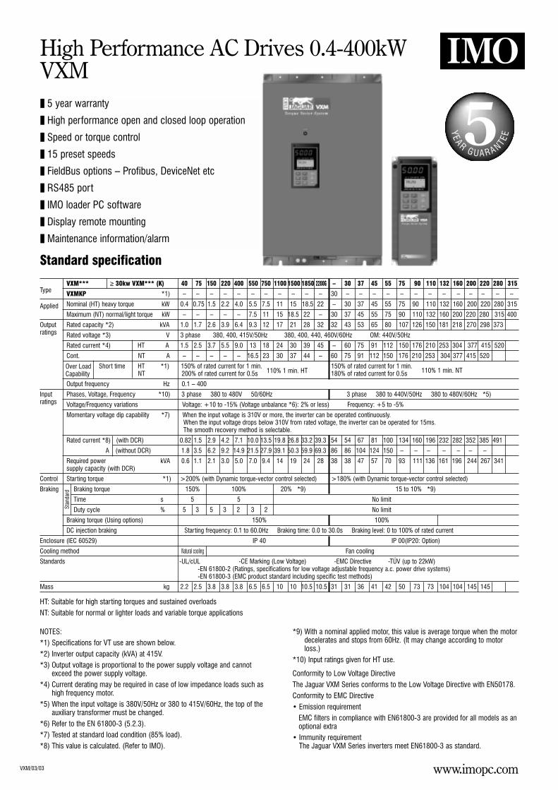
High Performance AC Drives 0.4-400kWVXM
YE A R
G U A R A NTEE
Standard specification
VXM/03/03
5 year warranty
High performance open and closed loop operation
Speed or torque control
15 preset speeds
FieldBus options – Profibus, DeviceNet etc
RS485 port
IMO loader PC software
Display remote mounting
Maintenance information/alarm
VXM*** ≥ 30kw VXM*** (K) 40 75 150 220 400 550 750 1100 1500 1850 2200G – 30 37 45 55 75 90 110 132 160 200 220 280 315Type VXMKP *1) – – – – – – – – – – – 30 – – – – – – – – – – – – –
Applied Nominal (HT) heavy torque kW 0.4 0.75 1.5 2.2 4.0 5.5 7.5 11 15 18.5 22 – 30 37 45 55 75 90 110 132 160 200 220 280 315
Maximum (NT) normal/light torque kW – – – – – 7.5 11 15 18.5 22 – 30 37 45 55 75 90 110 132 160 200 220 280 315 400
Output Rated capacity *2) kVA 1.0 1.7 2.6 3.9 6.4 9.3 12 17 21 28 32 32 43 53 65 80 107 126 150 181 218 270 298 373 ratings Rated voltage *3) V 3 phase 380, 400, 415V/50Hz 380, 400, 440, 460V/60Hz OM: 440V/50Hz
Rated current *4) HT A 1.5 2.5 3.7 5.5 9.0 13 18 24 30 39 45 – 60 75 91 112 150 176 210 253 304 377 415 520
Cont. (VT use) NT A – – – – – 16.5 23 30 37 44 – 60 75 91 112 150 176 210 253 304 377 415 520
Short time HT *1) 150% of rated current for 1 min. 150% of rated current for 1 min.(CT use) NT 200% of rated current for 0.5s 180% of rated current for 0.5s
Output frequency Hz 0.1 – 400
Input Phases, Voltage, Frequency *10) 3 phase 380 to 480V 50/60Hz 3 phase 380 to 440V/50Hz 380 to 480V/60Hz *5)ratings Voltage/Frequency variations Voltage: +10 to -15% (Voltage unbalance *6): 2% or less) Frequency: +5 to -5%
Momentary voltage dip capability *7) When the input voltage is 310V or more, the inverter can be operated continuously.When the input voltage drops below 310V from rated voltage, the inverter can be operated for 15ms.The smooth recovery method is selectable.
Rated current *8) (with DCR) 0.82 1.5 2.9 4.2 7.1 10.0 13.5 19.8 26.8 33.2 39.3 54 54 67 81 100 134 160 196 232 282 352 385 491
A (without DCR) 1.8 3.5 6.2 9.2 14.9 21.5 27.9 39.1 50.3 59.9 69.3 86 86 104 124 150 – – – – – – –
Required power kVA 0.6 1.1 2.1 3.0 5.0 7.0 9.4 14 19 24 28 38 38 47 57 70 93 111 136 161 196 244 267 341 supply capacity (with DCR)
Control Starting torque *1) >200% (with Dynamic torque-vector control selected) >180% (with Dynamic torque-vector control selected)
Braking Braking torque 150% 100% 20% *9) 15 to 10% *9)
Time s 5 5 No limit
Duty cycle % 5 3 5 3 2 3 2 No limit
Braking torque (Using options) 150% 100%
DC injection braking Starting frequency: 0.1 to 60.0Hz Braking time: 0.0 to 30.0s Braking level: 0 to 100% of rated current
Enclosure (IEC 60529) IP 40 IP 00(IP20: Option)
Cooling method Natural cooling Fan cooling
Standards -UL/cUL -CE Marking (Low Voltage) -EMC Directive -TÜV (up to 22kW)-EN 61800-2 (Ratings, specifications for low voltage adjustable frequency a.c. power drive systems)-EN 61800-3 (EMC product standard including specific test methods)
Mass kg 2.2 2.5 3.8 3.8 3.8 6.5 6.5 10 10 10.5 10.5 31 31 36 41 42 50 73 73 104 104 145 145
Stan
dard
HT: Suitable for high starting torques and sustained overloadsNT: Suitable for normal or lighter loads and variable torque applications
NOTES:*1) Specifications for VT use are shown below.*2) Inverter output capacity (kVA) at 415V. *3) Output voltage is proportional to the power supply voltage and cannot
exceed the power supply voltage. *4) Current derating may be required in case of low impedance loads such as
high frequency motor. *5) When the input voltage is 380V/50Hz or 380 to 415V/60Hz, the top of the
auxiliary transformer must be changed. *6) Refer to the EN 61800-3 (5.2.3). *7) Tested at standard load condition (85% load). *8) This value is calculated. (Refer to IMO).
*9) With a nominal applied motor, this value is average torque when the motordecelerates and stops from 60Hz. (It may change according to motorloss.)
*10) Input ratings given for HT use.
Conformity to Low Voltage DirectiveThe Jaguar VXM Series conforms to the Low Voltage Directive with EN50178.Conformity to EMC Directive• Emission requirement
EMC filters in compliance with EN61800-3 are provided for all models as anoptional extra
• Immunity requirementThe Jaguar VXM Series inverters meet EN61800-3 as standard.
110% 1 min. NT110% 1 min. HTOver LoadCapability
www.imopc.com
www.imopc.com
High Performance AC Drives 0.4-400kWVXM
VXM/03/03
Common specificationItem Explanation
Output Maximum frequency 50 to 400Hz *1)frequency Base frequency 25 to 400Hz *1)
Starting frequency 0.2 to 60Hz, Holding time: 0.0 to 10.0s
Carrier frequency *2) HD use, heavy duty LD use light/normal duty0.75 to 15kHz (55kW or smaller) *3) 0.75 to 15kHz (22kW or smaller)0.75 to 10kHz (75kW or larger) 0.75 to 10kHz (30 to 75kW)
0.75 to 6kHz (90kW or larger)
Accuracy (Stability) • Analog setting : ±0.2% of maximum frequency (at 25 ±10˚C)• Digital setting : ±0.01% of maximum frequency (at -10 to +50˚C)
Setting resolution • Analog setting : 1/3000 of maximum frequency ex.) 0.02Hz at 60Hz, 0.04Hz at 120Hz, (0.15Hz at 400Hz : EN)• Digital setting : 0.01Hz at maximum frequency of up to 99.99Hz (0.1Hz at Maximum frequency of 100Hz and above)• LINK setting : 1/20000 of maximum frequency ex.) 0.003Hz at 60Hz, 0.006Hz at 120Hz, (0.02Hz at 400Hz : EN) • 0.01Hz (Fixed)
Control Control method • V/f control (Sinusoidal PWM control) • Dynamic torque-vector control (Sinusoidal PWM control) • Vector control with PG (*) (EN only)
Voltage/freq. (V/f) characteristic Adjustable at base and maximum frequency, with AVR control : 320 to 480V
Torque boost Selectable by load characteristics: Constant torque load (Auto/manual), variable torque (manual)
Operation method • KEYPAD operation : or key, key
• Digital input signal operation : FWD or REV command, Coast-to-stop command, etc.
• LINK operation : RS485 (Standard)Profibus-DP, Interbus-S, DeviceNet, Modbus Plus, CAN open (Option)
Frequency setting • KEYPAD operation : or key(Frequency command) • External potentiometer (*) : 1 to 5k (1/2W)
• Analog input : 0 to +10VDC (0 to +5VDC), 4 to 20mA DC(Reversible) 0 to ±10VDC (0 to ±5VDC) . . . Reversible operation by polarised signal can be selected.
(Inverse) +10 to 0VDC, 20 to 4mA DC . . . Inverse mode operation can be selected.
• UP/DOWN control : Output frequency increases when UP signal is ON, and decreases when DOWN signal is ON.
• Multistep frequency : Up to 16 different frequencies can be selected by digital input signal.
• Pulse train input (*) : 0 to 100kp/s
• Digital signal (parallel) (*) : 16-bit binary
• LINK operation : RS485 (Standard)• Profibus-DP, Interbus-S, DeviceNet, Modbus Plus, CAN open (Option)
• Programmed PATTERN operation: Maximum 7 stages
Jogging operation • or key, FWD or REV digital input signal
Running status signal Transistor output (4 points) : RUN, FAR, FDT, OL, LU, TL, etc.
Relay output (2 points) : Same as transistor output • Alarm output (for any fault)
Analog output (1 point) : Output frequency, output current, output torque, etc.
Pulse output (1 point) : Output frequency, output current, output torque, etc.
Acceleration/Deceleration time 0.01 to 3600s : Independently adjustable acceleration and deceleration • 4 different times are selectable.
Mode select : Linear, S-curve (weak), S-curve (strong), Non-linear
Active drive When the acceleration time reaches 60s, the motor output torque is automatically reduced to rated torque.After 60s the motor operation mode is changed to torque limiting operation.The acceleration time is automatically extended up to 3 times.
Frequency limiter High and low limiter can be preset.
Bias frequency Bias frequency can be preset.
Gain for frequency setting Gain for frequency setting can be preset (0.0 to 200.0%) ex.) Analog input 0 to +5VDC with 200% gain results in maximum frequency at 5VDC.
Skip frequency control Skip frequency (3 points) and its common skip hysteresis width (0 to 30Hz) can be preset.
Rotating motor pick up (Flying start) A rotating motor (including inverse rotating mode) can be smoothly picked up without stopping the motor (speed search method).
Auto-restart after momentary power Automatic restart is available without stopping motor after a momentary power failure (speed search method). When “Smooth recovery”failure mode is selected, the motor speed drop is held minimum. (The inverter searches the motor speed and smoothly returns to setting frequency.)
Line/Inverter changeover operation Controls the switching operation between line power and inverter. The inverter has internal sequence function.
Slip compensation The inverter output frequency is controlled according to the load torque to keep motor speed constant. When the valueis set at “0.00” and “Torque-vector” is set at “active”, the compensation value is automatically set.
Slip compensation can be preset for the second motor.
Droop operation The motor speed droops in proportional to output torque (-9.9 to 0.0Hz).
Torque limiting • When the motor torque reaches a preset limiting level, this function automatically adjusts the output frequency to prevent the inverter from tripping due to an overcurrent. • Torque limiting 1 and 2 can be individually set, and are selectable with a digital input signal.
Torque control Output torque (or load factor) can be controlled with an analog input signal.
PID control This function can control flow rate pressure, etc. (with an analog feedback signal.)• Reference • KEYPAD operation ( or key): Setting freq./Max. freq. X 100 (%) • PATTERN operation : Setting freq./Max. freq. X 100 (%)
signal • Voltage input (Terminal 12 and V2) : 0 to +10V DC • DI option input (*) : BCD, setting freq./Max. freq. X 100 (%)• Current input (Terminal C1) : 4 to 20mA DC • Binary, full scale/100 (%)• Reversible operation with polarity (Terminal 12) : 0 to ±10V DC • Multistep frequency setting : Setting freq./Max freq. X 100 (%)• Reversible operation with polarity (Terminal 12 + V1) : 0 to ±10V DC • RS485 : Setting freq./Max freq. X 100 (%)• Inverse mode operation (Terminal 12 and V2) : +10 to 0V DC• Inverse mode operation (Terminal C1) : 20 to 4mA DC
• Feedback • Terminal 12 (0 to +10V DC or +10 to 0V DC)signal • Terminal C1 (4 to 20mA DC or 20 to 4mA DC)
Setti
ng
NOTES: (*) Option *1) For application at 120Hz or above, please contact IMO. *2) Inverter may automatically reduce carrier frequency, in accordance with ambienttemperature or output current for protection purposes. *3) The minimum carrier frequency changes depending on maximum output frequency.
www.imopc.com
High Performance AC Drives 0.4-400kWVXM continued
VXM/03/03
Common specification continuedItem Explanation
Control Automatic deceleration Torque limiter 1 (braking) is set at “F41:0” (Same as Torque limiter 2 (braking).• In deceleration : The deceleration time is automatically extended up to 3 times the setting time for tripless operation even if braking resistor not used.• In constant speed operation : Based on regenerative energy, the frequency is increased and tripless operation is active.
Second motor’s setting This function is used for two motors switching operation.• The second motor’s V/f characteristics (base and maximum frequency) can be preset.• The second motor’s circuit parameter can be preset. Torque-vector control can be applied to both motors.
Energy saving operation This function minimises inverter and motor losses at light load.
Fan stop operation This function is used for silent operation or extending the fan’s lifetime.
Universal DI Transmits to main controller of LINK operation.
Universal DO Outputs command signal from main controller of LINK operation.
Universal AO Outputs analog signal from main controller of LINK operation.
Zero speed control (*) The motor speed is controlled with the speed reference of zero – (holding torque).
Positioning control (*) The SY option card can be used for positioning control by differential counter method.
Synchronised operation (*) The function controls the synchronised operation between 2 axes with encoders.
Indication Operating mode (Running) LED monitor LCD monitor (English, German, French, Spanish, Italian, Japanese)
• Output frequency 1 (before slip compensation) (Hz)
• Output frequency 2 (after slip compensation) (Hz)
• Setting frequency (Hz)
• Output current (A)
• Output voltage (V)
• Motor synchronous speed (r/min)
• Line speed (m/min)
• Load shaft speed (r/min)
• Torque calculation value (%)
• Input power (kW)
• PID reference value (“F01”)
• PID reference value (Remote) (“C30”)
• PID feedback value
• Trip history: Cause of trip by code (even when main power supply is off, trip history data of the last 4 trips are retained).
Stopping Selected setting value or output value
Trip mode Displays the cause of trip by codes as follows.
• OC1 (Overcurrent during acceleration)
• OC2 (Overcurrent during deceleration)
• OC3 (Overcurrent running at constant speed)
• EF (Ground fault)
• Lin (Input phase loss)
• FUS (Fuse blown)
• OU1 (Overvoltage during acceleration)
• OU2 (Overvoltage during deceleration)
• OU3 (Overvoltage running at constant speed)
• LU (Undervoltage)
• OH1 (Overheating at heat sink)
• OH2 (External thermal relay tripped)
• OH3 (Overtemperature of inside air)
• dBH (Overheating of DB circuit)
• OL1 (Motor 1 overload)
• OL2 (Motor 2 overload)
• OLU (Inverter unit overload)
• OS (Overspeed)
• PG (PG error)
• Er1 (Memory error)
• Er2 (KEYPAD panel communication error)
• Er3 (CPU error)
• Er4 (Option error)
• Er5 (Option error)
• Er7 (Output phase loss error, impedance imbalance)
• Er8 (RS485 error)
Charge lamp • When the DC link circuit voltage is higher than 50V, the charge lamp is ON.
Operation monitor and alarm monitorOperation monitor• Displays operation guidance• Bargraph:
Output frequency (%), output current (A), output torque (%)Alarm monitor• The alarm data is displayed when the inverter trips.
Function setting and monitorFunction settingDisplays function codes and its data or data code, andchanges the data value.Operation condition• Output frequency (Hz) • Motor synchronous speed (r/min)• Output current (A) • Load shaft speed (r/min)• Output voltage (V) • Line speed (m/min)• Torque calculation value (%)• PID reference value• Setting frequency (Hz) • PID feedback value• Operation condition • Driving torque limiter setting value (%)
(FWD/REV, IL, VL/LU, TL) • Braking torque limiter setting value (%)Tester function(I/O check)• Digital I/O: (ON), (OFF)• Analog I/O: (V), (mA), (H), (p/s)Maintenance data• Operation time (h) • Cooling fan operation time (h)• DC link circuit voltage (V) • Communication error times• Temperature of inside air (˚C) (KEYPAD, RS485, Option)• Temperature of heat sink (˚C) • ROM version• Maximum current (A) (Inverter, KEYPAD, Option)• Main circuit capacitor life (%)• Control PC board life (h)Load factor calculation• Measurement time (s) • Average current (A)• Maximum current (A) • Average braking power (%)Alarm data• Output frequency (Hz) • Temperature of inside air (˚C)• Output current (A) • Heat sink temperature (˚C)• Output voltage (V) • Communication error times• Torque calculation value (%) (KEYPAD, RS485, Option)• Setting frequency (Hz) • Digital input terminal condition• Operation condition (Remote, communication)
(FWD/REV, IL, VL/LU, TL) • Transistor output terminal condition• Operation time (h) • Trip history code• DC link circuit voltage (V) • Multiple alarm occurrence
www.imopc.com
High Performance AC Drives 0.4-400kWVXM continued
VXM/03/03
Common specification continuedItem Explanation
Protection Overload Protects the inverter by electronic thermal and detection of inverter temperature.
Overvoltage Detects DC link circuit overvoltage, and stops the inverter. 400V series: 800VDC.
Undervoltage Detects DC link circuit undervoltage, and stops the inverter. 400V series: 400VDC.
Input phase loss Phase loss protection for power line input.
Overheating Protects the inverter by detection of inverter temperature.
Short-circuit Short-circuit protection for inverter output circuit.
Ground fault • Ground fault protection for inverter output circuit (3 phase current detection method).• Zero-phase current detection method (30kW or larger).
Motor overload • Electronic thermal overload relay can be selected for standard motor or inverter rated motor.• Thermal time constant (0.5 to 75.0 minutes) can be preset for a special motor.• The second motor’s electronic thermal overload relay can be preset for 2-motor changeover operation.
DB resistor overheating • Prevents DB resistor overheating by internal electronic thermal overload relay (7.5kW or smaller).• Prevents DB resistor overheating by external thermal overload relay attached to DB resistor (11kW or larger).(The inverter stops discharge operation to protect the DB resistor).
Stall prevention • Controls the output frequency to prevent (overcurrent) trip when the output current exceeds the limit value during acceleration.• Lowers the output frequency to hold almost constant torque when the output current exceeds the limit value during operation at constant speed.• Controls the output frequency to prevent (overvoltage) trip when the DC link circuit voltage exceeds the limit value during deceleration.
Output phase loss When the inverter executes auto-tuning, detects each phase impedance imbalance and displays an Error code.
Motor protection by PTC thermistor When the motor temperature exceeds allowable value, the inverter trips automatically.
Auto reset When the inverter is tripped it can be set to automatically reset and start.
Condition Installation location Free from corrosive gases, flammable gases, oil mist, dusts and direct sunlight. Indoor use only.(Installation Altitude 1000m or less. Applicable to 3000m with power derating (-10%/1000m).and
Ambient temperature -10 to +50˚C. For inverters of 22kW or smaller, remove the ventilation covers when operating it at a temperature of 40˚C or above.operation)
Ambient humidity 5 to 95%RH (non-condensing).
Vibration 3mm from 2 to less than 9Hz, 9.8m/s2 from 9 to less than 20Hz2m/s2 from 20 to less than 55Hz, 1m/s2 from 55 to less than 200Hz
Storage condition Temperature: -25 to +65˚C, Humidity: 5 to 95%RH (non-condensing)
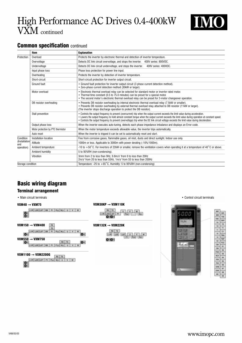
Basic wiring diagramTerminal arrangement
• Control circuit terminals• Main circuit terminals
VXM40 VXM75
VXM150 VXM400
VXM550 VXM750
VXM1100 VXM2200G
VXM30KP VXM110K
VXM132K VXM220K
www.imopc.com
High Performance AC Drives 0.4-400kWVXM continued
VXM/03/03
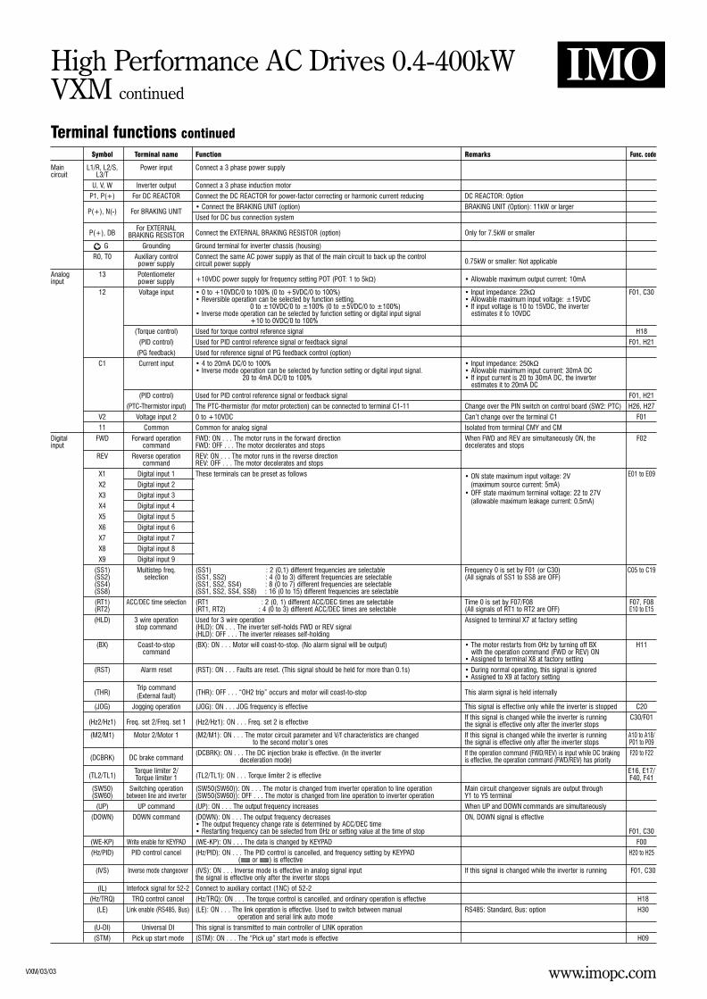
Terminal functions continuedSymbol Terminal name Function Remarks Func. code
Main L1/R, L2/S, Power input Connect a 3 phase power supplycircuit L3/T
U, V, W Inverter output Connect a 3 phase induction motor
P1, P(+) For DC REACTOR Connect the DC REACTOR for power-factor correcting or harmonic current reducing DC REACTOR: Option
P(+), N(-) For BRAKING UNIT• Connect the BRAKING UNIT (option) BRAKING UNIT (Option): 11kW or larger
Used for DC bus connection system
P(+), DBFor EXTERNAL
Connect the EXTERNAL BRAKING RESISTOR (option) Only for 7.5kW or smallerBRAKING RESISTOR
G Grounding Ground terminal for inverter chassis (housing)
R0, T0 Auxiliary control Connect the same AC power supply as that of the main circuit to back up the control0.75kW or smaller: Not applicablepower supply circuit power supply
Analog 13 Potentiometer+10VDC power supply for frequency setting POT (POT: 1 to 5kΩ) • Allowable maximum output current: 10mAinput power supply
12 Voltage input • 0 to +10VDC/0 to 100% (0 to +5VDC/0 to 100%) • Input impedance: 22kΩ F01, C30• Reversible operation can be selected by function setting. • Allowable maximum input voltage: ±15VDC
0 to ±10VDC/0 to ±100% (0 to ±5VDC/0 to ±100%) • If input voltage is 10 to 15VDC, the inverter • Inverse mode operation can be selected by function setting or digital input signal estimates it to 10VDC
+10 to 0VDC/0 to 100%
(Torque control) Used for torque control reference signal H18
(PID control) Used for PID control reference signal or feedback signal F01, H21
(PG feedback) Used for reference signal of PG feedback control (option)
C1 Current input • 4 to 20mA DC/0 to 100% • Input impedance: 250kΩ• Inverse mode operation can be selected by function setting or digital input signal. • Allowable maximum input current: 30mA DC
20 to 4mA DC/0 to 100% • If input current is 20 to 30mA DC, the inverter estimates it to 20mA DC
(PID control) Used for PID control reference signal or feedback signal F01, H21
(PTC-Thermistor input) The PTC-thermistor (for motor protection) can be connected to terminal C1-11 Change over the PIN switch on control board (SW2: PTC) H26, H27
V2 Voltage input 2 0 to +10VDC Can’t change over the terminal C1 F01
11 Common Common for analog signal Isolated from terminal CMY and CM
Digital FWD Forward operation FWD: ON . . . The motor runs in the forward direction When FWD and REV are simultaneously ON, the F02input command FWD: OFF . . . The motor decelerates and stops decelerates and stops
REV Reverse operation REV: ON . . . The motor runs in the reverse directioncommand REV: OFF . . . The motor decelerates and stops
X1 Digital input 1 These terminals can be preset as follows • ON state maximum input voltage: 2V E01 to E09
X2 Digital input 2 (maximum source current: 5mA)
X3 Digital input 3 • OFF state maximum terminal voltage: 22 to 27V
X4 Digital input 4(allowable maximum leakage current: 0.5mA)
X5 Digital input 5
X6 Digital input 6
X7 Digital input 7
X8 Digital input 8
X9 Digital input 9
(SS1) Multistep freq. (SS1) : 2 (0,1) different frequencies are selectable Frequency 0 is set by F01 (or C30) C05 to C19(SS2) selection (SS1, SS2) : 4 (0 to 3) different frequencies are selectable (All signals of SS1 to SS8 are OFF)(SS4) (SS1, SS2, SS4) : 8 (0 to 7) different frequencies are selectable(SS8) (SS1, SS2, SS4, SS8) : 16 (0 to 15) different frequencies are selectable
(RT1) ACC/DEC time selection (RT1 : 2 (0, 1) different ACC/DEC times are selectable Time 0 is set by F07/F08 F07, F08(RT2) (RT1, RT2) : 4 (0 to 3) different ACC/DEC times are selectable (All signals of RT1 to RT2 are OFF) E10 to E15
(HLD) 3 wire operation Used for 3 wire operation Assigned to terminal X7 at factory settingstop command (HLD): ON . . . The inverter self-holds FWD or REV signal
(HLD): OFF . . . The inverter releases self-holding
(BX) Coast-to-stop (BX): ON . . . Motor will coast-to-stop. (No alarm signal will be output) • The motor restarts from 0Hz by turning off BX H11command with the operation command (FWD or REV) ON
• Assigned to terminal X8 at factory setting
(RST) Alarm reset (RST): ON . . . Faults are reset. (This signal should be held for more than 0.1s) • During normal operating, this signal is ignored• Assigned to X9 at factory setting
(THR)Trip command
(THR): OFF . . . “OH2 trip” occurs and motor will coast-to-stop This alarm signal is held internally(External fault)
(JOG) Jogging operation (JOG): ON . . . JOG frequency is effective This signal is effective only while the inverter is stopped C20
(Hz2/Hz1) Freq. set 2/Freq. set 1 (Hz2/Hz1): ON . . . Freq. set 2 is effectiveIf this signal is changed while the inverter is running C30/F01the signal is effective only after the inverter stops
(M2/M1) Motor 2/Motor 1 (M2/M1): ON . . . The motor circuit parameter and V/f characteristics are changed If this signal is changed while the inverter is running A10 to A18/to the second motor’s ones the signal is effective only after the inverter stops P01 to P09
(DCBRK) DC brake command(DCBRK): ON . . . The DC injection brake is effective. (In the inverter If the operation command (FWD/REV) is input while DC braking F20 to F22
deceleration mode) is effective, the operation command (FWD/REV) has priority
(TL2/TL1)Torque limiter 2/
(TL2/TL1): ON . . . Torque limiter 2 is effectiveE16, E17/
Torque limiter 1 F40, F41
(SW50) Switching operation (SW50(SW60)): ON . . . The motor is changed from inverter operation to line operation Main circuit changeover signals are output through(SW60) between line and inverter (SW50(SW60)): OFF . . . The motor is changed from line operation to inverter operation Y1 to Y5 terminal
(UP) UP command (UP): ON . . . The output frequency increases When UP and DOWN commands are simultaneously
(DOWN) DOWN command (DOWN): ON . . . The output frequency decreases ON, DOWN signal is effective• The output frequency change rate is determined by ACC/DEC time• Restarting frequency can be selected from 0Hz or setting value at the time of stop F01, C30
(WE-KP) Write enable for KEYPAD (WE-KP): ON . . . The data is changed by KEYPAD F00
(Hz/PID) PID control cancel (Hz/PID): ON . . . The PID control is cancelled, and frequency setting by KEYPAD H20 to H25( or ) is effective
(IVS) Inverse mode changeover (IVS): ON . . . Inverse mode is effective in analog signal input If this signal is changed while the inverter is running F01, C30the signal is effective only after the inverter stops
(IL) Interlock signal for 52-2 Connect to auxiliary contact (1NC) of 52-2
(Hz/TRQ) TRQ control cancel (Hz/TRQ): ON . . . The torque control is cancelled, and ordinary operation is effective H18
(LE) Link enable (RS485, Bus) (LE): ON . . . The link operation is effective. Used to switch between manual RS485: Standard, Bus: option H30operation and serial link auto mode
(U-DI) Universal DI This signal is transmitted to main controller of LINK operation
(STM) Pick up start mode (STM): ON . . . The “Pick up” start mode is effective H09

www.imopc.com
High Performance AC Drives 0.4-400kWVXM continued
VXM/03/03
Terminal functions continuedSymbol Terminal name Function Remarks Func. code
Digital (PG/Hz) SY-PG enabled (PG/Hz): ON . . . Synchronised operation or PG-feedback operation is effective Optioninput (SYC) Synchronised command (SYC): ON . . . The motor is controlled for synchronised operation between 2 axes with PGs Option
(ZERO) Zero speed command (ZERO): ON . . . The motor speed is controlled with the speed reference of zero This function can be selected at PG feedback control. Option
(STOP 1) Forced stop command (STOP 1): OFF . . . The motor decelerates and stops
(STOP 2) Forced stop command (STOP 2): OFF . . . The motor decelerates and stops with Deceleration time 4 E15with Deceleration time 4
(EXITE) Pre-exciting command (EXITE): ON . . . Motor magnetic flux is established before starting in PG vector mode
PLC PLC terminal Connect PLC power supply to avoid malfunction of the inverter that has SINK typedigital input, when PLC power supply is off
P24 DC voltage supply DC voltage supply (+24V, maximum 100mA)
Analog FMA Analog monitor Output voltage (0 to 10VDC) is proportional to selected function’s value as follows. Allowable maximum output current: 2mA F30 to F31output The proportional coefficient and bias value can be preset.
• Output frequency 1 (Before slip compensation) (0 to max. frequency)• Output frequency 2 (After slip compensation) (0 to max. frequency)• Output current (0 to 200%)• Output voltage (0 to 200%)• Output torque (0 to 200%)• Load factor (0 to 200%)• Input power (0 to 200%)• PID feedback value (0 to 100%)• PG feedback value (0 to max. speed)• DC link circuit voltage (0 to 1000V)
(11) (Common) • Universal AO (0 to 100%)
Pulse FMP Pulse rate monitor • Pulse rate mode: Pulse rate is proportional to selected function’s value* (50% duty pulse) Allowable maximum output current: 2mA F33 to F35Output • Average voltage mode: Average voltage is proportional to selected function’s value*
(2670p/s pulse width control)
(CM) (Common) • Function to be output is same as those of analog output (FMA)
CM Common Common for pulse output Isolated from terminal CMY and 11
Transistor Y1 Transistor output 1 Output the selected signals from the following items • ON state maximum output voltage: 3V E20 to E23output Y2 Transistor output 2 (Allowable maximum sink current: 50mA)
Y3 Transistor output 3 • OFF state maximum leakage current: 0.1mA
Y4 Transistor output 4 (Allowable maximum voltage: 27V)
(RUN) Inverter running Outputs ON signal when the output frequency is higher than starting frequency
(FAR) Frequency equivalence Outputs ON signal when the difference between output frequency and setting frequency is E30signal smaller than FAR hysteresis width
(FDT1) Frequency level detection Outputs ON signal by comparison of output frequency and preset value (level and hysteresis) E31, E32
Undervoltage(LU) Outputs ON signal when the inverter stops by undervoltage while the operation command is ON.detection signal
(B/D) Torque polarity Outputs ON signal in braking or stopping mode, and OFF signal in driving mode
(TL) Torque limiting Output ON signal when the inverter is in torque-limiting mode
(IPF) Auto-restarting Outputs ON signal during auto restart operation (Instantaneous power failure) mode. (Including “restart time”)
(OL1) Overload early warning • Outputs ON signal when the electronic thermal value is higher than preset alarm level E33 to E35• Outputs ON signal when the output current value is higher than preset alarm level
(KP) KEYPAD operation mode Outputs ON signal when the inverter is in KEYPAD operation mode F02
(STP) Inverter stopping Outputs ON signal when the inverter is in stopping mode or in DC braking mode
(RDY) Ready output Outputs ON signal when the inverter is ready for operation
(SW88) Line/Inv changeover Outputs 88’s ON signal for Line/Inverter changeover operation(for 88)
(SW52-2) Line/Inv changeover Outputs 52-2’s ON signal for Line/Inverter changeover operation(for 52-2)
(SW52-1) Line/Inv changeover Outputs 52-1’s ON signal for Line/Inverter changeover operation(for 52-1)
(SWM2) Motor2/Motor1 Outputs the motor changeover switch ON signal from motor 1 to motor 2 A01 to A18
(AX) Auxiliary terminal Used for auxiliary circuit of 52-1 Refer to wiring diagram example(for 52-1) (Same function as AX1, AX2 terminal Jaguar VX series. (30kW or larger)
(TU) Time-up signal Outputs time up signal (100ms ON pulse) at every stage end of PATTERN operation C21 to C28
(TO) Cycle completion signal Outputs one cycle completion signal (100ms ON pulse) at PATTERN operation
(STG1) Stage No. indication 1 Outputs Pattern operation’s stage No. by signals STG1, STG2 and STG4(STG2) Stage No. indication 2(STG4) Stage No. indication 4
(AL1) Alarm indication 1 Outputs trip alarm No. by signals AL1, AL2, AL4 and AL8(AL2) Alarm indication 2(AL4) Alarm indication 4(AL8) Alarm indication 8
(FAN) Fan operation signal Outputs the inverter cooling fan operation status signal H06
(TRY) Auto-resetting Outputs ON signal at auto resetting mode. (Including “Reset interval”) H04, H05
(U-DO) Universal DO Outputs command signal from main controller of Link operation
(OH) Overheat early warning Outputs ON signal when the heat sink temperature is higher than (trip level – 10˚C) andoutputs OFF signal when the temperature is lower than (trip level – 15˚C)
(SY) Synchronisation Synchronisation completion signal for synchronised operation Optioncompletion signal
(LIFE) Lifetime alarm Outputs ON signal when the calculated lifetime is longer than preset alarm level
(FDT2) 2nd Freq. level 2nd outputs ON signal by comparison of output frequency and preset value (FDT2 level)detection
(OL2) 2nd OL level early 2nd outputs ON signal when the output current value is larger than preset alarm levelwarning (OL2 level)
(C1OFF) Terminal C1 off signal Outputs ON signal when the C1 current is smaller than 2mA
(N-EX) Speed existence signal Outputs ON signal when motor speed is larger than stop speed* on vector control with PG *stop speed = stop frequency (F25) x 120/pole (r/m) F25
CMY Common (transistor Common for transistor output signal Isolated from terminals CM and 11output)
Relay 30A, 30B Alarm relay output Outputs a contact signal when a protective function is activated • Contact rating: F36output 30C Changeable exciting mode active or non-exciting mode active by function “F36” 250VAC, 0.3A, cosø=0.3 E24
Y5A, Y5C Relay output Functions can be selected the same as Y1 to Y4 48VDC, 0.5A, non-inductive E25
Changeable excitation mode active or non-excitation mode active by function “E25”
Link DX+, DX-, RS485 I/O terminal Connect the RS485 link signalSD
www.imopc.comVXM/03/03
High Performance AC Drives 0.4-400kWVXM continued
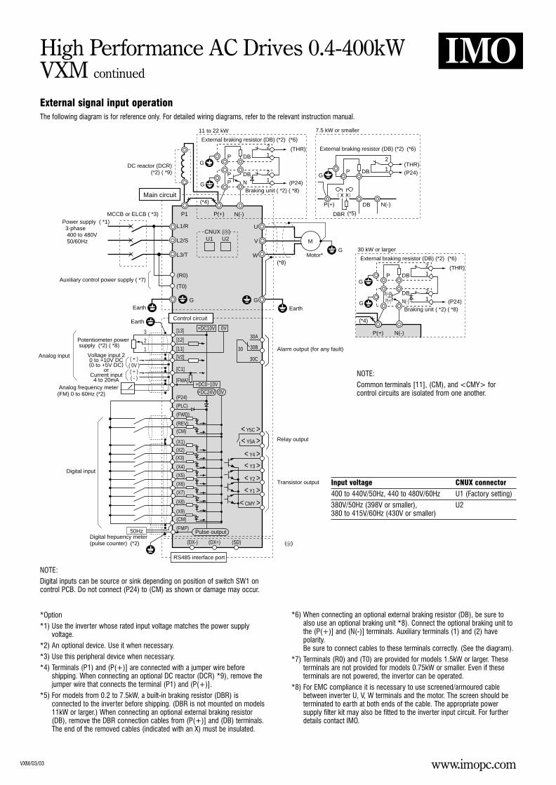
*Option*1) Use the inverter whose rated input voltage matches the power supply
voltage.*2) An optional device. Use it when necessary.*3) Use this peripheral device when necessary.*4) Terminals (P1) and (P(+)] are connected with a jumper wire before
shipping. When connecting an optional DC reactor (DCR) *9), remove thejumper wire that connects the terminal (P1) and (P(+)].
*5) For models from 0.2 to 7.5kW, a built-in braking resistor (DBR) isconnected to the inverter before shipping. (DBR is not mounted on models11kW or larger.) When connecting an optional external braking resistor(DB), remove the DBR connection cables from (P(+)] and (DB) terminals.The end of the removed cables (indicated with an X) must be insulated.
*6) When connecting an optional external braking resistor (DB), be sure toalso use an optional braking unit *8). Connect the optional braking unit tothe (P(+)] and (N(-)] terminals. Auxiliary terminals (1) and (2) havepolarity.Be sure to connect cables to these terminals correctly. (See the diagram).
*7) Terminals (R0) and (T0) are provided for models 1.5kW or larger. Theseterminals are not provided for models 0.75kW or smaller. Even if theseterminals are not powered, the invertor can be operated.
*8) For EMC compliance it is necessary to use screened/armoured cablebetween inverter U, V, W terminals and the motor. The screen should beterminated to earth at both ends of the cable. The appropriate powersupply filter kit may also be fitted to the inverter input circuit. For furtherdetails contact IMO.
NOTE:Common terminals [11], (CM), and <CMY> forcontrol circuits are isolated from one another.
( + ) ( - )
( + ) ( 0V )
L1/R
L2/S
L3/T
U
V
WG
GG
M
N(-)P(+)P1
(R0)
(T0)
(X9)(CM)
(FMP)
(DX-) (DX+) (SD)
(X1)
(PLC)
(FWD)
(REV)(CM)
(X8)
(X7)
(X6)
(X5)
(X4)
(X3)(X2)
0V
30A
30B
30C
30
0V
+DC10V
+DC24V+DC0~10V
[13]
[12]
[11]
[C1]
[V2]
[FMA]
11 to 22 kW
MCCB or ELCB ( *3) Power supply ( *1) 3-phase 400 to 480V 50/60Hz
Main circuit
(*5)
Earth
Earth
Earth
Control circuit
Analog input
Digital input
RS485 interface port
Pulse output
Motor*(*8)
Alarm output (for any fault)
Relay output
Transistor output
50Hz
1
2
3
Auxiliary control power supply ( *7)
Potentiometer power supply (*2) ( *8)
Analog frequency meter (FM) 0 to 60Hz (*2)
DC reactor (DCR) (*2) ( *9)
Voltage input 20 to +10V DC(0 to +5V DC)
orCurrent input
4 to 20mA
External braking resistor (DB) (*2) (*6)
External braking resistor (DB) (*2) (*6)
Braking unit ( *2) ( *8)
GDB
2
1
DB N(-)
DBR
(THR)
(THR)
(P24)
(P24)
P
P(+)
G
G
N
DBP
2
1
21
P
P
DB
(*4)
7.5 kW or smaller
Digital frepuency meter(pulse counter) (*2)
< Y5C >< Y5A >
< Y4 >
< Y1 >< Y2 >
< Y3 >
< CMY >
(P24)
(*4)
30 kW or larger
External braking resistor (DB) (*2) (*6)
Braking unit ( *2) ( *8)
(THR)
(P24)G
G
N(-)
DBP(+)R
2
1
21
P
P(+)
DB
CNUX ( )U1
x x
U2
N(-)P(+)
Input voltage CNUX connector
400 to 440V/50Hz, 440 to 480V/60Hz U1 (Factory setting)
380V/50Hz (398V or smaller), U2380 to 415V/60Hz (430V or smaller)
NOTE:Digital inputs can be source or sink depending on position of switch SW1 oncontrol PCB. Do not connect (P24) to (CM) as shown or damage may occur.
External signal input operationThe following diagram is for reference only. For detailed wiring diagrams, refer to the relevant instruction manual.
www.imopc.comVXM/03/03
High Performance AC Drives 0.4-400kWVXM continued
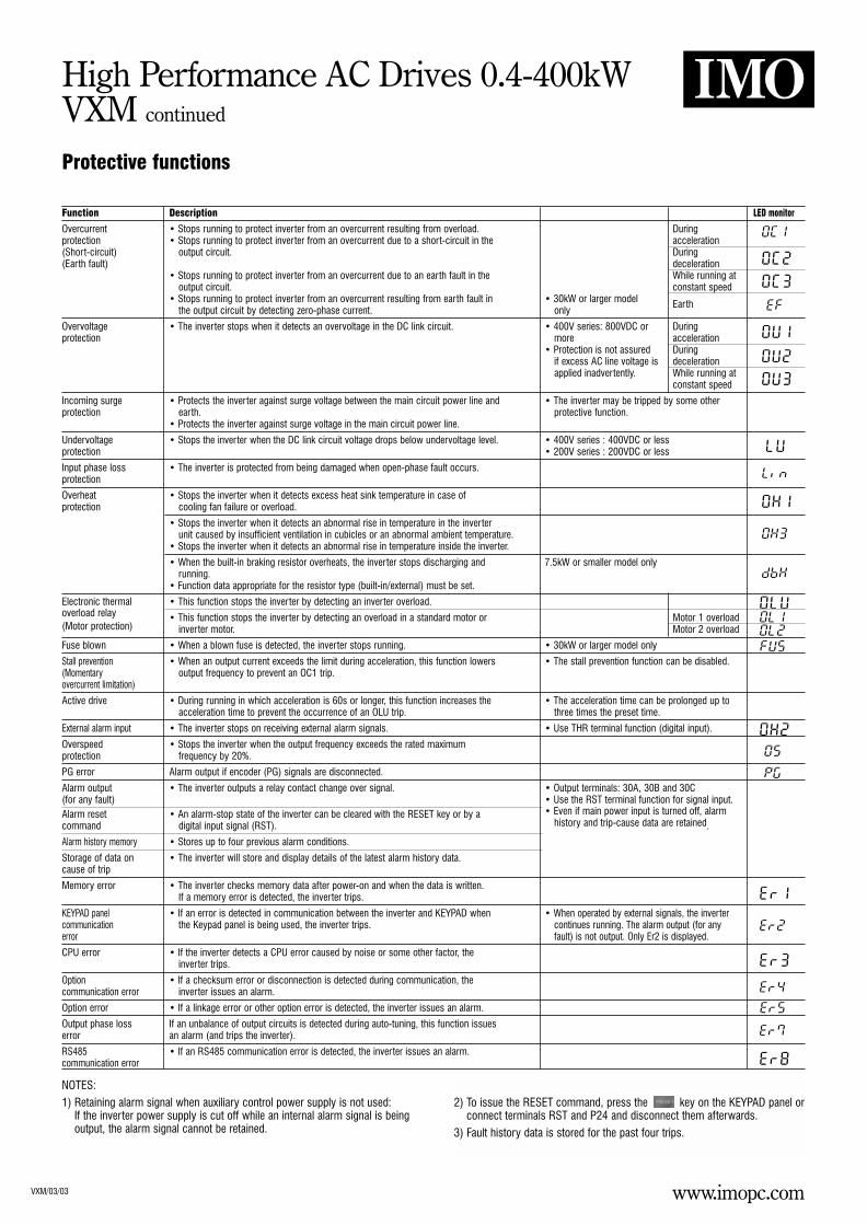
Protective functions
Function Description LED monitor
Overcurrent • Stops running to protect inverter from an overcurrent resulting from overload. Duringprotection • Stops running to protect inverter from an overcurrent due to a short-circuit in the acceleration(Short-circuit) output circuit. During(Earth fault) deceleration
• Stops running to protect inverter from an overcurrent due to an earth fault in the While running atoutput circuit. constant speed
• Stops running to protect inverter from an overcurrent resulting from earth fault in • 30kW or larger modelthe output circuit by detecting zero-phase current. only
Earth
Overvoltage • The inverter stops when it detects an overvoltage in the DC link circuit. • 400V series: 800VDC or Duringprotection more acceleration
• Protection is not assured Duringif excess AC line voltage is decelerationapplied inadvertently. While running at
constant speed
Incoming surge • Protects the inverter against surge voltage between the main circuit power line and • The inverter may be tripped by some otherprotection earth. protective function.
• Protects the inverter against surge voltage in the main circuit power line.
Undervoltage • Stops the inverter when the DC link circuit voltage drops below undervoltage level. • 400V series : 400VDC or lessprotection • 200V series : 200VDC or less
Input phase loss • The inverter is protected from being damaged when open-phase fault occurs.protection
Overheat • Stops the inverter when it detects excess heat sink temperature in case ofprotection cooling fan failure or overload.
• Stops the inverter when it detects an abnormal rise in temperature in the inverterunit caused by insufficient ventilation in cubicles or an abnormal ambient temperature.
• Stops the inverter when it detects an abnormal rise in temperature inside the inverter.
• When the built-in braking resistor overheats, the inverter stops discharging and 7.5kW or smaller model onlyrunning.
• Function data appropriate for the resistor type (built-in/external) must be set.
Electronic thermal • This function stops the inverter by detecting an inverter overload.overload relay • This function stops the inverter by detecting an overload in a standard motor or Motor 1 overload(Motor protection) inverter motor. Motor 2 overload
Fuse blown • When a blown fuse is detected, the inverter stops running. • 30kW or larger model only
Stall prevention • When an output current exceeds the limit during acceleration, this function lowers • The stall prevention function can be disabled.(Momentary output frequency to prevent an OC1 trip.overcurrent limitation)
Active drive • During running in which acceleration is 60s or longer, this function increases the • The acceleration time can be prolonged up toacceleration time to prevent the occurrence of an OLU trip. three times the preset time.
External alarm input • The inverter stops on receiving external alarm signals. • Use THR terminal function (digital input).
Overspeed • Stops the inverter when the output frequency exceeds the rated maximumprotection frequency by 20%.
PG error Alarm output if encoder (PG) signals are disconnected.
Alarm output • The inverter outputs a relay contact change over signal. • Output terminals: 30A, 30B and 30C(for any fault) • Use the RST terminal function for signal input.Alarm reset • An alarm-stop state of the inverter can be cleared with the RESET key or by a • Even if main power input is turned off, alarmcommand digital input signal (RST). history and trip-cause data are retained.
Alarm history memory • Stores up to four previous alarm conditions.
Storage of data on • The inverter will store and display details of the latest alarm history data.cause of trip
Memory error • The inverter checks memory data after power-on and when the data is written.If a memory error is detected, the inverter trips.
KEYPAD panel • If an error is detected in communication between the inverter and KEYPAD when • When operated by external signals, the invertercommunication the Keypad panel is being used, the inverter trips. continues running. The alarm output (for anyerror fault) is not output. Only Er2 is displayed.
CPU error • If the inverter detects a CPU error caused by noise or some other factor, theinverter trips.
Option • If a checksum error or disconnection is detected during communication, thecommunication error inverter issues an alarm.
Option error • If a linkage error or other option error is detected, the inverter issues an alarm.
Output phase loss If an unbalance of output circuits is detected during auto-tuning, this function issueserror an alarm (and trips the inverter).
RS485 • If an RS485 communication error is detected, the inverter issues an alarm.communication error
NOTES:1) Retaining alarm signal when auxiliary control power supply is not used:
If the inverter power supply is cut off while an internal alarm signal is beingoutput, the alarm signal cannot be retained.
2) To issue the RESET command, press the key on the KEYPAD panel orconnect terminals RST and P24 and disconnect them afterwards.
3) Fault history data is stored for the past four trips.

www.imopc.comVXM/03/03
High Performance AC Drives 0.4-400kWVXM continued
External dimensionsFig 1 Fig 2
Fig 3 Fig 4
VXM40 VXM75
VXM550 VXM750 VXM1100 VXM2200G
VXM150 VXM400
Type D D4 D5
VXM40 130 36.5 80
VXM75 145 51.5 95
www.imopc.comVXM/03/03
High Performance AC Drives 0.4-400kWVXM continued
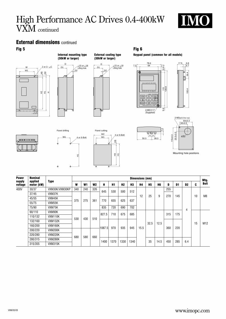
External dimensions continued
Fig 5 Fig 6Internal mounting type External cooling type (30kW or larger) (30kW or larger)
Keypad panel (common for all models)
W
W1
C
Panel cutting
2 or 3 - ¿CD
H2
H5
H1
H4
H
D2
W1W2 4 or 6-Bolt
D1¿15 or ¿18 Lifting hole
H1
H3
H6
Panel drilling
W1 4 or 6-Bolt
H1
D2
D
D1¿15 or ¿18 Lifting hole
Power Nominal Dimensions (mm) Mtg.supply applied TypeBoltvoltage motor (kW) W W1 W2 H H1 H2 H3 H4 H5 H6 D D1 D2 C
400V 30/37 VXM30K/VXM30KP 340 240 326645 530 500 512
255
37/45 VXM37K12 25 9 270 145 10 M8
45/55 VXM45K375 275 361 770 655 625 637
55/75 VXM55K
75/90 VXM75K 835 720 690 7024
90/110 VXM90K827.5 710 675 685 315 175
110/132 VXM110K530 430 510
132/160 VXM132K32.5 12.5 15 M12
160/200 VXM160K1087.5 970 935 945 15.5 360 220
200/220 VXM200K
220/280 VXM220K680 580 660
280/315 VXM280K1400 1370 1330 1340 35 14.5 450 285 6.4
315/355 VXM315K
www.imopc.comVXM/03/03
High Performance AC Drives 0.4-400kWVXM continued
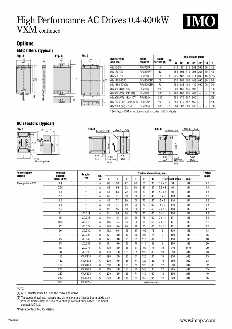
OptionsEMC filters (typical)
DC reactors (typical)
Dimensions (mm)Inverter type Filter Rated Fig.(and use) required current (A) W W1 H H1 H2 H3 D
VXM40-75 RFM75FP 5 116 90 310 293 265 10 42
VXM150-400 RFM400FP 12 155 105 310 293 265 10 45
VXM550-750 RFM750FP 35 A 225 167 331 311 260 10 47.5
VXM1100-1500 RFM1500FP 50 250 185 480 449 400 20 70
VXM1850-2200G RFM2200FP 72 250 185 480 449 400 20 70
VXM30K (CT) -30KP RFM30K 100 200 166 435 408 – – 130
VXM30K (VT) -90K (CT) RFM90K 180 B 200 166 495 468 – – 160
VXM90K (VT) -132K (CT) RFM132K 280 250 170 587 560 – – 205
VXM132K (VT) -220K (CT) RFM220K 400 C 250 170 587 560 – – 205
VXM220K (VT) -315K RFM315K 880 * 364 300 688 648 – – 180
Power supply Nominal Typical dimensions, mm Typicalvoltage applied Reactor Fig. mass
motor (kW) type A B C D E F G H Terminal screw (kg)
Three phase 400V 0.4 * A 66 56 72 90 60 35 5.2 x 8 94 M4 1.0
0.75 * A 66 56 72 90 60 40 5.2 x 8 94 M4 1.4
1.5 * A 66 56 72 90 60 45 5.2 x 8 94 M4 1.6
2.2 * A 86 71 80 100 65 45 6 x 9 110 M4 2.0
4.0 * A 86 71 80 100 70 50 6 x 9 110 M4 2.6
5.5 * A 86 71 80 100 70 50 6 x 9 110 M4 2.6
7.5 * A 111 95 80 100 75 60 7 x 11 130 M5 4.2
11 VXLC11 A 111 95 80 100 75 60 7 x 11 130 M5 4.3
15 VXLC15 A 146 124 96 120 75 60 7 x 11 171 M5 5.9
18.5 VXLC18 A 146 124 96 120 85 65 7 x 11 171 M6 7.2
22 VXLC22 A 146 124 96 120 85 65 7 x 11 171 M6 7.2
30 VXLC30 B 152 90 115 157 100 78 8 130 M8 13
37 VXLC37 B 171 110 110 150 100 75 8 150 M8 15
45 VXLC45 B 171 110 125 165 110 82 8 150 M8 18
55 VXLC55 B 171 110 130 170 110 85 8 150 M8 20
75 VXLC75 C 190 160 115 151 100 75 10 240 M10 20
90 VXLC90 C 190 160 125 161 120 80 10 250 ø12 23
110 VXLC110 C 190 160 125 161 120 80 10 250 ø12 25
132 VXLC132 C 200 170 135 171 120 85 10 260 ø12 28
160 VXLC160 C 210 180 135 171 120 85 12 290 ø12 32
200 VXLC200 C 210 180 135 171 140 90 12 295 ø12 35
220 VXLC220 C 220 190 135 171 140 90 12 300 ø15 40
280 VXLC280 C 220 190 145 181 150 95 12 320 ø15 45
315 VXLC315 Available soon
NOTE:(1) A DC reactor must be used for 75kW and above.(2) The above drawings, masses and dimensions are intended as a guide only.
Product details may be subject to change without prior notice. If in doubtcontact IMO Ltd.
*Please contact IMO for details.
Fig. A Fig. B Fig. C
Fig. A Fig. B Fig. C
* See Jaguar VXM instruction manual or contact IMO for details
www.imopc.comVXM/03/03
High Performance AC Drives 0.4-400kWVXM continued
Options continued
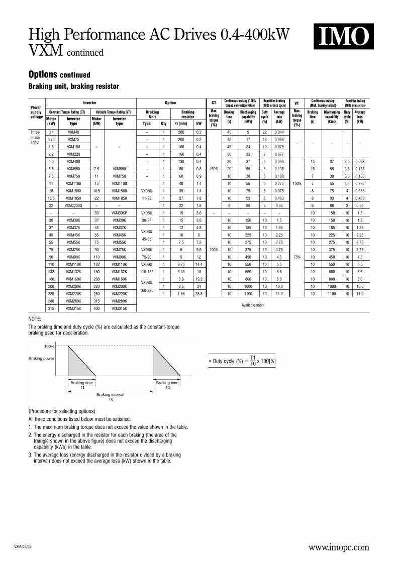
Braking unit, braking resistor
Continuous braking (100% Repetitive braking Continuous braking Repetitive braking
PowerInverter Option CT
torque conversion value) (100s or less cycle) VT (MAX. braking torque) (100s or less cycle)
supply Constant Torque Rating (CT) Variable Torque Rating (VT) Braking Braking Max. Braking Discharging Duty Average Max. Braking Discharging Duty Averagevoltage Motor Inverter Motor Inverter Unit resistor braking time capability cycle loss braking time capability cycle loss
(kW) type (kW) type Type Qty Ω(min) kWtorque (s) (kWs) (%) (kW) torque (s) (kWs) (%) (kW)(%) (%)
Three- 0.4 VXM40 – 1 200 0.2 45 9 22 0.044phase 0.75 VXM75 – 1 200 0.2 45 17 18 0.068400V
1.5 VXM150 – – – 1 160 0.4 45 34 10 0.075– – – – –
2.2 VXM220 – 1 160 0.4 30 33 7 0.077
4.0 VXM400 – 1 130 0.4 20 37 5 0.093 15 37 3.5 0.093
5.5 VXM550 7.5 VXM550 – 1 80 0.8 150% 20 55 5 0.138 15 55 3.5 0.138
7.5 VXM750 11 VXM750 – 1 60 0.9 10 38 5 0.188 7 38 3.5 0.188
11 VXM1100 15 VXM1100 1 40 1.4 10 55 5 0.275 100% 7 55 3.5 0.275
15 VXM1500 18.5 VXM1500 VXDBU 1 35 1.4 10 75 5 0.375 8 75 4 0.375
18.5 VXM1850 22 VXM1850 11-22 1 27 1.8 10 93 5 0.463 8 93 4 0.463
22 VXM2200G – – 1 22 1.8 8 88 5 0.55 6 88 3 0.55
– – 30 VXM30KP VXDBU 1 15 3.6 – – – – – 10 150 10 1.5
30 VXM30K 37 VXM30K 30-37 1 15 3.6 10 150 10 1.5 10 150 10 1.5
37 VXM37K 45 VXM37K 1 12 4.8 10 185 10 1.85 10 185 10 1.85
45 VXM45K 55 VXM45KVXDBU
1 10 6 10 225 10 2.25 10 225 10 2.25
55 VXM55K 75 VXM55K45-55
1 7.5 7.2 10 275 10 2.75 10 275 10 2.75
75 VXM75K 90 VXM75K VXDBU 1 6 9.6 100% 10 375 10 3.75 10 375 10 3.75
90 VXM90K 110 VXM90K 75-90 1 5 12 10 450 10 4.5 75% 10 450 10 4.5
110 VXM110K 132 VXM110K VXDBU 1 3.75 14.4 10 550 10 5.5 10 550 10 5.5
132 VXM132K 160 VXM132K 110-132 1 3.33 18 10 660 10 6.6 10 660 10 6.6
160 VXM160K 200 VXM160KVXDBU
1 3.0 19.2 10 800 10 8.0 10 800 10 8.0
200 VXM200K 220 VXM200K 1 2.5 24 10 1000 10 10.0 10 1000 10 10.0
220 VXM220K 280 VXM220K160-220
1 1.88 28.8 10 1100 10 11.0 10 1100 10 11.0
280 VXM280K 315 VXM280K
315 VXM315K 400 VXM315KAvailable soon
NOTE:The braking time and duty cycle (%) are calculated as the constant-torquebraking used for deceleration.
(Procedure for selecting options)All three conditions listed below must be satisfied.1. The maximum braking torque does not exceed the value shown in the table.2. The energy discharged in the resistor for each braking (the area of the
triangle shown in the above figure) does not exceed the dischargingcapability (kWs) in the table.
3. The average loss (energy discharged in the resistor divided by a brakinginterval) does not exceed the average loss (kW) shown in the table.
T1• Duty cycle (%) = T0 x 100[%]
Braking power
100%
Braking time T1
Braking time T1
Braking interval T0
www.imopc.comVXM/03/03
High Performance AC Drives 0.4-400kWVXM continued
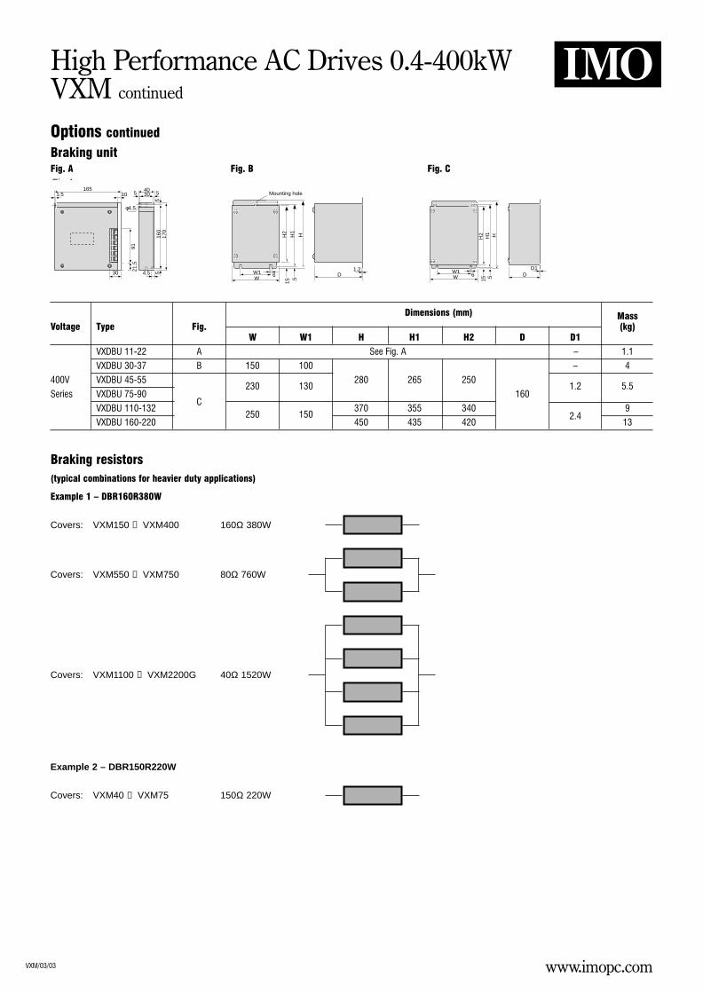
Options continued
Braking unit
Braking resistors (typical combinations for heavier duty applications)
Dimensions (mm) MassVoltage Type Fig. (kg)
W W1 H H1 H2 D D1
VXDBU 11-22 A See Fig. A – 1.1
VXDBU 30-37 B 150 100 – 4
400V VXDBU 45-55230 130
280 265 2501.2 5.5
Series VXDBU 75-90 160
VXDBU 110-132C
250 150370 355 340 9
VXDBU 160-220 450 435 4202.4
13
Example 1 – DBR160R380W
Covers: VXM150 → VXM400 160Ω 380W
Covers: VXM550 → VXM750 80Ω 760W
Covers: VXM1100 → VXM2200G 40Ω 1520W
Example 2 – DBR150R220W
Covers: VXM40 → VXM75 150Ω 220W
Fig.A165
1.5 10
30
N.P
55
55
21.5
91
170
160
4.5
4030
φ4.5
Mounting hole
H2
H1
H
D1.2
W6W1
15 .5
H2
H1 H
W 6W1
DD1
15 .5
Fig. A Fig. B Fig. C
www.imopc.comVXM/03/03
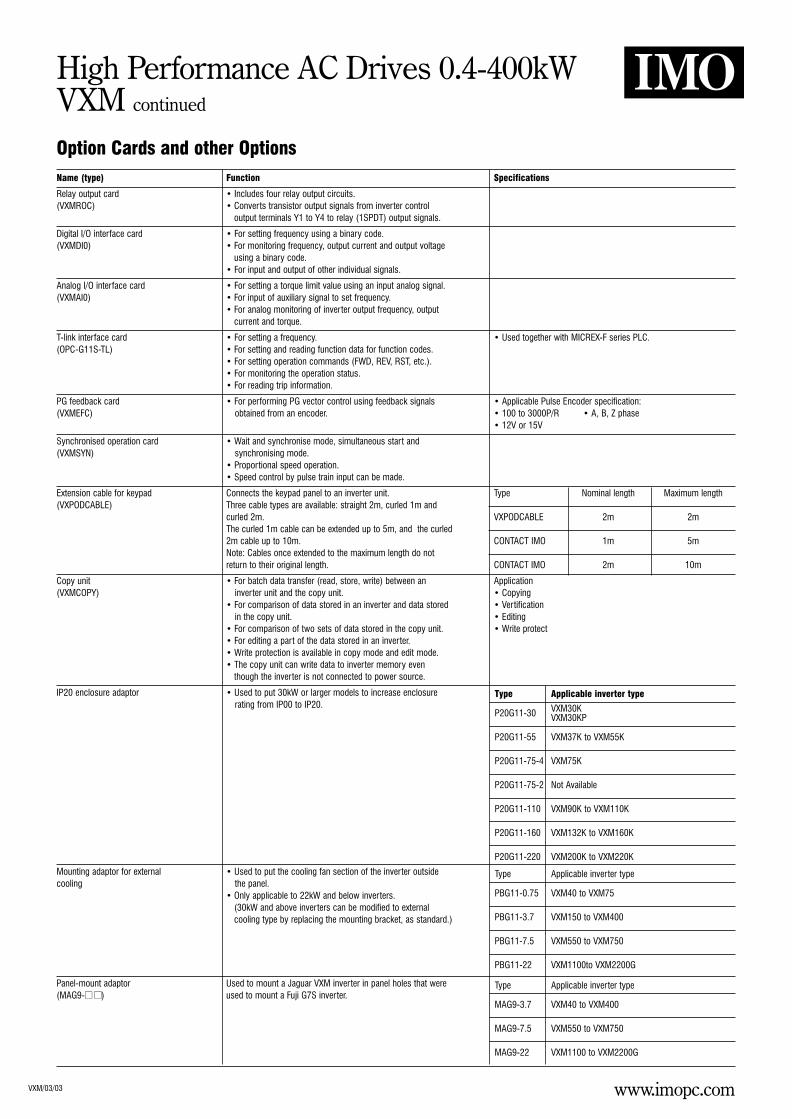
High Performance AC Drives 0.4-400kWVXM continued
Name (type) Function Specifications
Relay output card • Includes four relay output circuits.(VXMROC) • Converts transistor output signals from inverter control
output terminals Y1 to Y4 to relay (1SPDT) output signals.
Digital I/O interface card • For setting frequency using a binary code.(VXMDI0) • For monitoring frequency, output current and output voltage
using a binary code.• For input and output of other individual signals.
Analog I/O interface card • For setting a torque limit value using an input analog signal.(VXMAI0) • For input of auxiliary signal to set frequency.
• For analog monitoring of inverter output frequency, outputcurrent and torque.
T-link interface card • For setting a frequency. • Used together with MICREX-F series PLC.(OPC-G11S-TL) • For setting and reading function data for function codes.
• For setting operation commands (FWD, REV, RST, etc.).• For monitoring the operation status.• For reading trip information.
PG feedback card • For performing PG vector control using feedback signals • Applicable Pulse Encoder specification:(VXMEFC) obtained from an encoder. • 100 to 3000P/R • A, B, Z phase
• 12V or 15V
Synchronised operation card • Wait and synchronise mode, simultaneous start and(VXMSYN) synchronising mode.
• Proportional speed operation.• Speed control by pulse train input can be made.
Extension cable for keypad Connects the keypad panel to an inverter unit. Type Nominal length Maximum length(VXPODCABLE) Three cable types are available: straight 2m, curled 1m and
curled 2m. VXPODCABLE 2m 2mThe curled 1m cable can be extended up to 5m, and the curled2m cable up to 10m. CONTACT IMO 1m 5mNote: Cables once extended to the maximum length do notreturn to their original length. CONTACT IMO 2m 10m
Copy unit • For batch data transfer (read, store, write) between an Application(VXMCOPY) inverter unit and the copy unit. • Copying
• For comparison of data stored in an inverter and data stored • Vertificationin the copy unit. • Editing
• For comparison of two sets of data stored in the copy unit. • Write protect• For editing a part of the data stored in an inverter.• Write protection is available in copy mode and edit mode.• The copy unit can write data to inverter memory even
though the inverter is not connected to power source.
IP20 enclosure adaptor • Used to put 30kW or larger models to increase enclosurerating from IP00 to IP20.
Mounting adaptor for external • Used to put the cooling fan section of the inverter outsidecooling the panel.
• Only applicable to 22kW and below inverters.(30kW and above inverters can be modified to externalcooling type by replacing the mounting bracket, as standard.)
Panel-mount adaptor Used to mount a Jaguar VXM inverter in panel holes that were(MAG9- ) used to mount a Fuji G7S inverter.
Type Applicable inverter type
VXM30KP20G11-30 VXM30KP
P20G11-55 VXM37K to VXM55K
P20G11-75-4 VXM75K
P20G11-75-2 Not Available
P20G11-110 VXM90K to VXM110K
P20G11-160 VXM132K to VXM160K
P20G11-220 VXM200K to VXM220K
Type Applicable inverter type
PBG11-0.75 VXM40 to VXM75
PBG11-3.7 VXM150 to VXM400
PBG11-7.5 VXM550 to VXM750
PBG11-22 VXM1100to VXM2200G
Type Applicable inverter type
MAG9-3.7 VXM40 to VXM400
MAG9-7.5 VXM550 to VXM750
MAG9-22 VXM1100 to VXM2200G
Option Cards and other Options
www.imopc.comVXM/03/03
High Performance AC Drives 0.4-400kWVXM continued
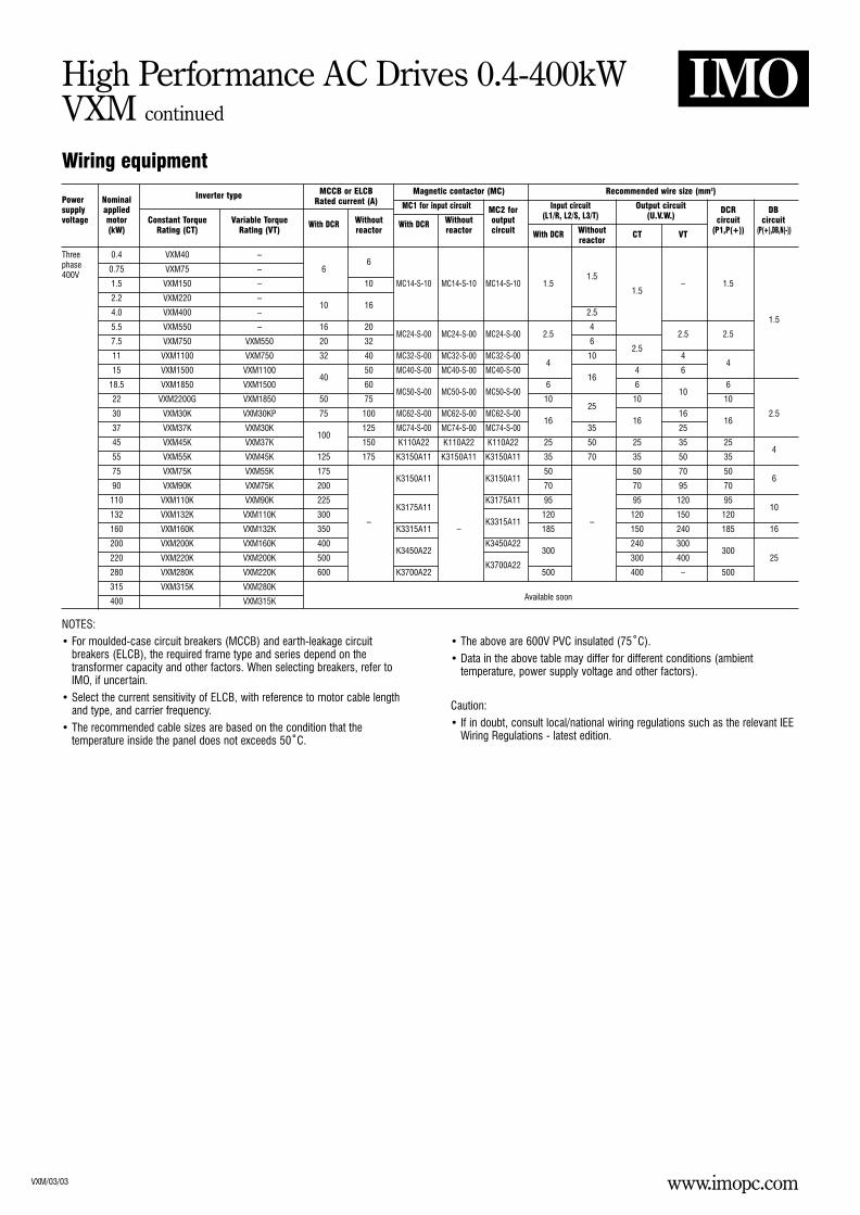
Wiring equipment
Power Nominal Inverter type MCCB or ELCB Magnetic contactor (MC) Recommended wire size (mm2)
supply appliedRated current (A) MC1 for input circuit MC2 for Input circuit Output circuit DCR DB
voltage motor Constant Torque Variable Torque With DCR Without With DCR Without output (L1/R, L2/S, L3/T) (U.V.W.) circuit circuit(kW) Rating (CT) Rating (VT) reactor reactor circuit With DCR Without CT VT (P1,P(+)) (P(+),DB,N(-))
reactor
Three 0.4 VXM40 –6phase 0.75 VXM75 – 6
400V1.5 VXM150 – 10 MC14-S-10 MC14-S-10 MC14-S-10 1.5
1.5– 1.5
2.2 VXM220 –10 16
1.5
4.0 VXM400 – 2.51.5
5.5 VXM550 – 16 20MC24-S-00 MC24-S-00 MC24-S-00 2.5
42.5 2.5
7.5 VXM750 VXM550 20 32 6
11 VXM1100 VXM750 32 40 MC32-S-00 MC32-S-00 MC32-S-00 102.5
4
15 VXM1500 VXM110040
50 MC40-S-00 MC40-S-00 MC40-S-004
4 64
18.5 VXM1850 VXM1500 60MC50-S-00 MC50-S-00
616
610
6
22 VXM2200G VXM1850 50 75MC50-S-00
10 10 10
30 VXM30K VXM30KP 75 100 MC62-S-00 MC62-S-00 MC62-S-0025
16 2.5
37 VXM37K VXM30K100
125 MC74-S-00 MC74-S-00 MC74-S-0016
3516
2516
45 VXM45K VXM37K 150 K110A22 K110A22 K110A22 25 50 25 35 25
55 VXM55K VXM45K 125 175 K3150A11 K3150A11 K3150A11 35 70 35 50 354
75 VXM75K VXM55K 175K3150A11 K3150A11
50 50 70 506
90 VXM90K VXM75K 200 70 70 95 70
110 VXM110K VXM90K 225K3175A11
K3175A11 95 95 120 9510
132 VXM132K VXM110K 300K3315A11
120–
120 150 120
160 VXM160K VXM132K 350–
K3315A11 – 185 150 240 185 16
200 VXM200K VXM160K 400K3450A22
K3450A22300
240 300
220 VXM220K VXM200K 500 300 400300
25
280 VXM280K VXM220K 600 K3700A22K3700A22
500 400 – 500
315 VXM315K VXM280K
400 VXM315K Available soon
NOTES:• For moulded-case circuit breakers (MCCB) and earth-leakage circuit
breakers (ELCB), the required frame type and series depend on thetransformer capacity and other factors. When selecting breakers, refer toIMO, if uncertain.
• Select the current sensitivity of ELCB, with reference to motor cable lengthand type, and carrier frequency.
• The recommended cable sizes are based on the condition that thetemperature inside the panel does not exceeds 50˚C.
• The above are 600V PVC insulated (75˚C).• Data in the above table may differ for different conditions (ambient
temperature, power supply voltage and other factors).
Caution:• If in doubt, consult local/national wiring regulations such as the relevant IEE
Wiring Regulations - latest edition.