high park chess house renovations
TRANSCRIPT
HIGH PARK CHESS HOUSE
RENOVATIONS
1879 Bloor Street West
Toronto, ON
Architectural | Mechanical | Electrical |
Structural
Specifications
Issued for Permits and Tender
January 2020
Project No. 1911
CHERIE NG ARCHITECT INC.
Tel: 416-898-1979
Consulting Engineers
Mechanical Consultant
T.W.A. Engineering Inc.
Electrical Consultant
Solid Ground Engineering
Structural Consultant
CSE Structural Engineering Inc.
SECTION 00 01 10 TABLE OF CONTENTS 1879 BLOOR STREET WEST | HIGH PARK CHESS HOUSE RENOVATIONS
PAGE 00 01 10.1 JANUARY 2020
CHERIE NG ARCHITECT INC. Project 1911
.1 Refer to Project Manual, Section 00 01 10 - Table of Contents, for indication of document responsibility (DR). Abbreviations for entity responsible for document preparation are as follows:
.2 A - Denotes documents prepared by Architect.
.3 S - Denotes documents prepared by Structural Engineer (on drawings).
.4 HC – Denotes documents prepare by Hardware Consultant.
.5 M - Denotes documents prepared by Mechanical Engineer.
.6 E - Denotes documents prepared by Electrical Engineer.
.7 O - Denotes documents prepared by Owner. DIVISION 00 – PROCUREMENT AND CONTRACTING REQUIREMENTS Document Title Discipline Pages 00 01 10 Table of Contents A 2 00 31 00 Information Available to Bidders A 1
- Designated Substance Survey O 20 - Report on Geotechnical Investigation
Proposed Interior Alternations and Retrofit Construction Chess House Club O 14
DIVISION 01 - GENERAL REQUIREMENT Document Title Discipline Pages 01 10 00 Scope of Work A / S / M / E 3 01 10 10 General Requirements A 30 DIVISION 02 - EXISTING CONDITIONS Document Title Discipline Pages 02 40 00 Demolition and Removals A 7 02 80 00 Management of Designated Substances A 3 DIVISION 05 - METALS Document Title Discipline Pages 05 50 00 Miscellaneous and Metal Fabrications A 7 DIVISION 06 - WOOD, PLASTICS, AND COMPOSITES Document Title Discipline Pages 06 10 00 Rough Carpentry A 5 06 20 00 Finish Carpentry A 5
SECTION 00 01 10 TABLE OF CONTENTS 1879 BLOOR STREET WEST | HIGH PARK CHESS HOUSE RENOVATIONS
PAGE 00 01 10.2 JANUARY 2020
CHERIE NG ARCHITECT INC. Project 1911
DIVISION 07 - THERMAL AND MOISTURE PROTECTION Document Title Discipline Pages 07 91 00 Sealants A 5 DIVISION 08 - OPENINGS Document Title Discipline Pages 08 11 13 Metal Doors and Frames A 7 08 70 00 Finish Hardware A 4 08 71 13 Automatic Door Equipment A 5 DIVISION 09 - FINISHES Document Title Discipline Pages 09 21 16 Gypsum Board A 10 09 30 00 Tile A 6 09 91 00 Painting A 10 09 97 13 High Performance Steel Coatings A 6 DIVISION 10 - SPECIALTIES Document Title Discipline Pages 10 28 13 Washroom Accessories A 4 DIVISION 22 – PLUMBING and DIVISION 23 – HVAC Document Title Discipline Pages See attached Mechanical Table of Contents. M 36 DIVISION 26 - ELECTRICAL Document Title Discipline Pages See attached Electrical Table of Contents. E 27 STRUCTURAL Document Title Discipline Pages See attached Structrual Table of Contents. S 67
END OF DOCUMENT

SECTION 00 31 00 INFORMATION AVAILABLE TO BIDDERS 1879 BLOOR STREET WEST | HIGH PARK CHESS HOUSE RENOVATIONS
PAGE 00 31 00.1 JANUARY 2020
CHERIE NG ARCHITECT INC. Project 1911
REPORT(S)
1.1 A copy of the following report(s) are appended under separate cover:
Designated Substance Survey Prepared by CGI Group
High Park Chess House – 1879 Bloor Street West December 8, 2016 Report on Geotechnical Investigation Proposed Interior Alternations and Retrofit Construction Chess House Club, High Park, 1879 Bloor St Prepared by Sirati & Partners Consultants Ltd. January 21, 2020
1.2 The report(s), by their nature, cannot reveal all conditions that exist or can occur on
the site. Should conditions be found to vary substantially from the report, immediately notify Consultant in writing and await instructions.
1.3 Contractor shall not be entitled to extra payment or extension of Contract Time for work which is required and which is reasonably inferable in the report(s) as being necessary.
END OF SECTION
Toronto Montreal Calgary Victoria Vancouver
DESIGNATED SUBSTANCE
SURVEY
at
High Park Chess House
1879 Bloor Street West
Toronto, Ontario
Prepared for
City of Toronto
Parks, Forestry, and Recreation
CCIG Project No: T1611451CA
December 8, 2016
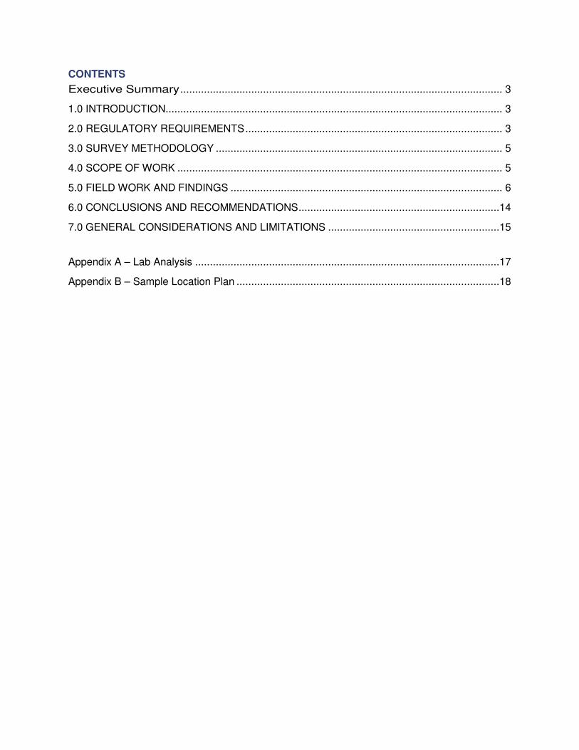
CONTENTS
Executive Summary ............................................................................................................. 3
1.0 INTRODUCTION.................................................................................................................. 3
2.0 REGULATORY REQUIREMENTS ....................................................................................... 3
3.0 SURVEY METHODOLOGY ................................................................................................. 5
4.0 SCOPE OF WORK .............................................................................................................. 5
5.0 FIELD WORK AND FINDINGS ............................................................................................ 6
6.0 CONCLUSIONS AND RECOMMENDATIONS ....................................................................14
7.0 GENERAL CONSIDERATIONS AND LIMITATIONS ..........................................................15
Appendix A – Lab Analysis .......................................................................................................17
Appendix B – Sample Location Plan .........................................................................................18
Designated Substance Survey 1879 Bloor Street West, Toronto, Ontario
Reference # T1611451CA
3
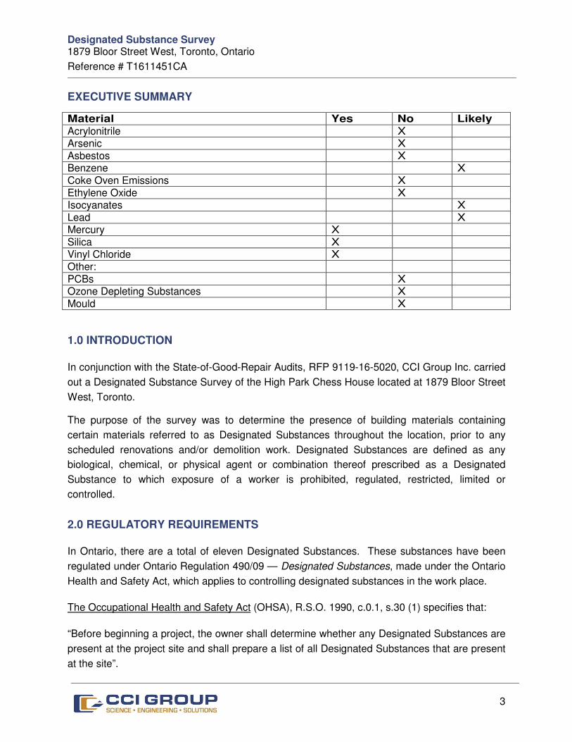
EXECUTIVE SUMMARY
Material Yes No Likely
Acrylonitrile X Arsenic X Asbestos X Benzene X Coke Oven Emissions X Ethylene Oxide X Isocyanates X Lead X Mercury X Silica X Vinyl Chloride X Other: PCBs X Ozone Depleting Substances X Mould X
1.0 INTRODUCTION
In conjunction with the State-of-Good-Repair Audits, RFP 9119-16-5020, CCI Group Inc. carried
out a Designated Substance Survey of the High Park Chess House located at 1879 Bloor Street
West, Toronto.
The purpose of the survey was to determine the presence of building materials containing
certain materials referred to as Designated Substances throughout the location, prior to any
scheduled renovations and/or demolition work. Designated Substances are defined as any
biological, chemical, or physical agent or combination thereof prescribed as a Designated
Substance to which exposure of a worker is prohibited, regulated, restricted, limited or
controlled.
2.0 REGULATORY REQUIREMENTS
In Ontario, there are a total of eleven Designated Substances. These substances have been
regulated under Ontario Regulation 490/09 — Designated Substances, made under the Ontario
Health and Safety Act, which applies to controlling designated substances in the work place.
The Occupational Health and Safety Act (OHSA), R.S.O. 1990, c.0.1, s.30 (1) specifies that:
“Before beginning a project, the owner shall determine whether any Designated Substances are
present at the project site and shall prepare a list of all Designated Substances that are present
at the site”.
Designated Substance Survey 1879 Bloor Street West, Toronto, Ontario
Reference # T1611451CA
4
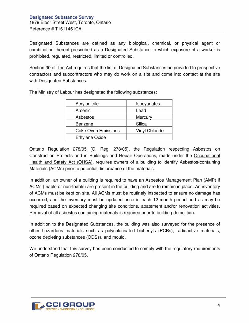
Designated Substances are defined as any biological, chemical, or physical agent or
combination thereof prescribed as a Designated Substance to which exposure of a worker is
prohibited, regulated, restricted, limited or controlled.
Section 30 of The Act requires that the list of Designated Substances be provided to prospective
contractors and subcontractors who may do work on a site and come into contact at the site
with Designated Substances.
The Ministry of Labour has designated the following substances:
Acrylonitrile Isocyanates
Arsenic Lead
Asbestos Mercury
Benzene Silica
Coke Oven Emissions Vinyl Chloride
Ethylene Oxide
Ontario Regulation 278/05 (O. Reg. 278/05), the Regulation respecting Asbestos on
Construction Projects and in Buildings and Repair Operations, made under the Occupational
Health and Safety Act (OHSA), requires owners of a building to identify Asbestos-containing
Materials (ACMs) prior to potential disturbance of the materials.
In addition, an owner of a building is required to have an Asbestos Management Plan (AMP) if
ACMs (friable or non-friable) are present in the building and are to remain in place. An inventory
of ACMs must be kept on site. All ACMs must be routinely inspected to ensure no damage has
occurred, and the inventory must be updated once in each 12-month period and as may be
required based on expected changing site conditions, abatement and/or renovation activities.
Removal of all asbestos containing materials is required prior to building demolition.
In addition to the Designated Substances, the building was also surveyed for the presence of
other hazardous materials such as polychlorinated biphenyls (PCBs), radioactive materials,
ozone depleting substances (ODSs), and mould.
We understand that this survey has been conducted to comply with the regulatory requirements
of Ontario Regulation 278/05.
Designated Substance Survey 1879 Bloor Street West, Toronto, Ontario
Reference # T1611451CA
5
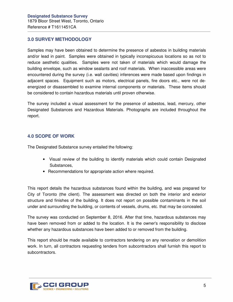
3.0 SURVEY METHODOLOGY
Samples may have been obtained to determine the presence of asbestos in building materials
and/or lead in paint. Samples were obtained in typically inconspicuous locations so as not to
reduce aesthetic qualities. Samples were not taken of materials which would damage the
building envelope, such as window sealants and roof materials. When inaccessible areas were
encountered during the survey (i.e. wall cavities) inferences were made based upon findings in
adjacent spaces. Equipment such as motors, electrical panels, fire doors etc., were not de-
energized or disassembled to examine internal components or materials. These items should
be considered to contain hazardous materials until proven otherwise.
The survey included a visual assessment for the presence of asbestos, lead, mercury, other
Designated Substances and Hazardous Materials. Photographs are included throughout the
report.
4.0 SCOPE OF WORK
The Designated Substance survey entailed the following:
• Visual review of the building to identify materials which could contain Designated
Substances,
• Recommendations for appropriate action where required.
This report details the hazardous substances found within the building, and was prepared for
City of Toronto (the client). The assessment was directed on both the interior and exterior
structure and finishes of the building. It does not report on possible contaminants in the soil
under and surrounding the building, or contents of vessels, drums, etc. that may be concealed.
The survey was conducted on September 8, 2016. After that time, hazardous substances may
have been removed from or added to the location. It is the owner's responsibility to disclose
whether any hazardous substances have been added to or removed from the building.
This report should be made available to contractors tendering on any renovation or demolition
work. In turn, all contractors requesting tenders from subcontractors shall furnish this report to
subcontractors.
Designated Substance Survey 1879 Bloor Street West, Toronto, Ontario
Reference # T1611451CA
6
5.0 FIELD WORK AND FINDINGS
Property Description
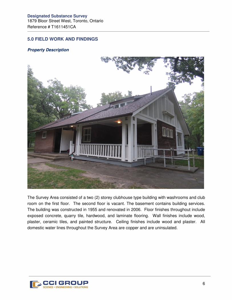
The Survey Area consisted of a two (2) storey clubhouse type building with washrooms and club
room on the first floor. The second floor is vacant. The basement contains building services.
The building was constructed in 1955 and renovated in 2006. Floor finishes throughout include
exposed concrete, quarry tile, hardwood, and laminate flooring. Wall finishes include wood,
plaster, ceramic tiles, and painted structure. Ceiling finishes include wood and plaster. All
domestic water lines throughout the Survey Area are copper and are uninsulated.
Designated Substance Survey 1879 Bloor Street West, Toronto, Ontario
Reference # T1611451CA
7
The following subsections detail our findings:
Asbestos
Background Information on Asbestos
Asbestos is a generic name that has been given to a group of naturally occurring fibrous
minerals. In the past, asbestos was commonly used as a component in building materials such
as insulation, fireproofing and acoustic or decorative panels. Although there are many types of
asbestos, the three main forms of commercial importance in Ontario are chrysotile, amosite and
crocidolite.
An Asbestos-Containing Material (ACM) is defined by O. Reg. 278/05 as a material that
contains 0.5 % or more asbestos by dry weight. ACMs are placed into two general classes,
“friable” and “non-friable” ACMs. Friable ACMs are those materials that when dry can be
crumbled, pulverized and reduced to powder by hand pressure. Typical friable ACMs include
acoustical or decorative texture coats, fireproofing, some ceiling tiles and thermal insulation.
Non-friable ACMs are much more durable as they are held together by a binder such as
cement, vinyl or asphalt. Typical non-friable ACMs include floor tiles, fire blankets, roofing
materials and cementitious products such as wallboards, pipes or siding.
It has been recognized that hazardous situations may exist in buildings where asbestos-
containing materials are found. This is especially true where asbestos fibres may become
airborne as a result of material ageing, physical damage, and water damage or air movement.
In contrast, there is little reason for concern if the asbestos is in good condition, has not been
damaged and is not in a location where it is likely to be disturbed.
Asbestos Survey Methodology
The asbestos survey included the identification of potential friable and non-friable asbestos-
containing materials within the facility.
The likelihood of ACMs being present in inaccessible areas such as behind chases and
bulkheads was determined by assessing the presence of asbestos-containing systems in
adjacent areas.
Fiberglass insulation was not submitted for analysis as it can be identified visually as non-
asbestos material.
Designated Substance Survey 1879 Bloor Street West, Toronto, Ontario
Reference # T1611451CA
8
Asbestos Survey Findings
No suspected ACMs were found during the survey.
• Mechanical Piping Insulation
Pipes are not insulated.
• Exterior Doors Caulking
Exterior doors caulking was not sampled as it is not expected to contain asbestos.
• Roofing Material
The roof is protected by asphalt shingles.
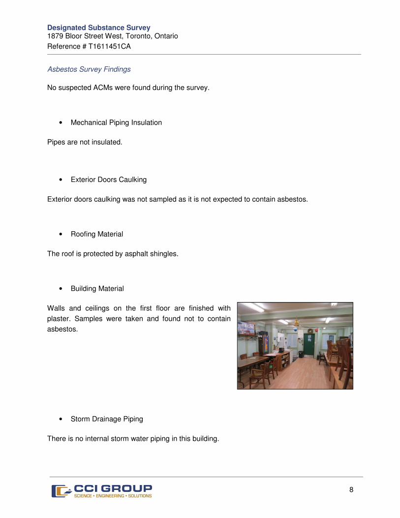
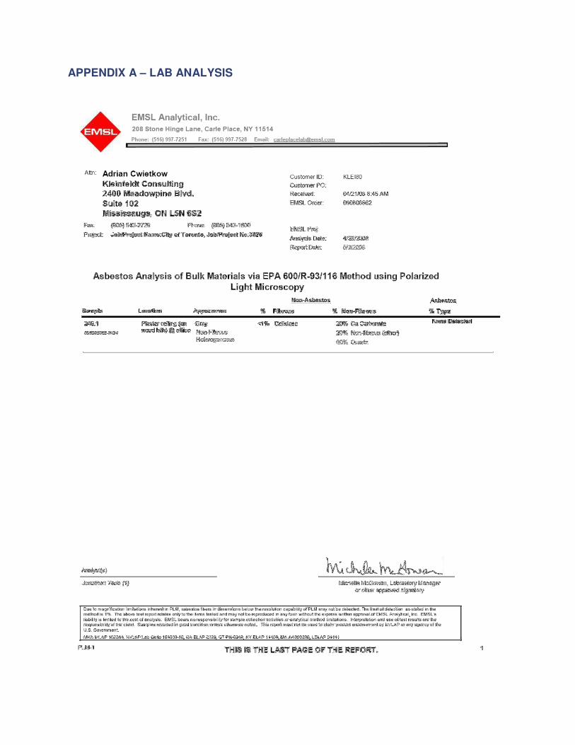
• Building Material
Walls and ceilings on the first floor are finished with
plaster. Samples were taken and found not to contain
asbestos.
• Storm Drainage Piping
There is no internal storm water piping in this building.

Designated Substance Survey 1879 Bloor Street West, Toronto, Ontario
Reference # T1611451CA
9
Lead
Background Information on Lead
Lead was a common additive in exterior and hard wearing paint applications. Lead was used to
prolong shelf life of paint and to increase its flexibility and durability to wear and weather. Acute
exposure to lead by inhalation or ingestion may cause headaches, fatigue, nausea, abdominal
cramps and joint pain. Chronic exposures can cause reduced haemoglobin production and
reduced lifespan. It has also been known to impact the body’s central and peripheral nervous
systems and brain function and has been linked to learning disabilities in children.
Currently in Ontario, there is no regulatory limit that determines what concentration of lead
constitutes a “lead containing material”. On October 21, 2010, Health Canada, under the
Hazardous Products Act, stated that the lead content in surface-coating materials, furniture, toys
and other articles for children, should not exceed 90mg/kg (0.009%, 90ppm). However, this is
intended for the importation or sale of products within Canada. Therefore, this is not to be
misconstrued as a limit established to define a lead-containing material or a limit with respect to
lead on construction projects.
Exposure to lead-containing materials is regulated under Ontario Regulation 490/09, Designated
Substances - made under the Occupational Health and Safety Act. Care must be taken to
prevent lead-containing particles from becoming airborne during the disturbance of lead-
containing surfaces (i.e., during renovation or demolition projects). All lead abatement work must
follow procedures outlined in the Guideline Lead on Construction Projects, issued in September
2004 (amended in April 2011) by the Occupational Health and Safety branch of the Ministry of
Labour.
Lead is known to have been used in solder on copper plumbing fixtures, in lead conduit pipes, in
lead-calcium battery plates, ammunition, and in nuclear and X-ray shielding devices. However,
these materials were not sampled during this investigation, but were noted where applicable.
Lead Findings
Based on the age of this building, it is expected that lead-based paint be found below newer
painted latex finishes. Lead may also be present in the soldered joints of copper piping found
within this building.
Designated Substance Survey 1879 Bloor Street West, Toronto, Ontario
Reference # T1611451CA
10
Mercury
Mercury is known to cause poisoning in humans through the inhalation of vapours, ingestion of
contaminated materials or skin absorption through direct contact with the liquid.
Precautions must be taken to prevent mercury vapours from becoming airborne during renovations
or demolition of the building. Exposure to airborne mercury is regulated under the Revised O. Reg.
490/09 as amended – Regulation respecting Mercury – made under the Occupational Health and
Safety Act; and under O. Reg. 558, which amended O. Reg. 347/90 (General - Waste
Management), mercury is classified as a Schedule 2(b) Hazardous Waste Chemical. Its hazardous
waste number is U151.
Mercury is found in products such as thermostats, temperature and pressure gauges,
fluorescent lamps and batteries. Mercury in products can be released to the environment
through breakage, or disposal at the end of a product's useful life. Improper disposal of these
mercury products poses a health and environmental risk to everyone. In addition, the disposal of
mercury-containing products can create wastes that are often classified as hazardous. Wastes
that leach mercury in concentrations exceeding Ontario Regulation 347/90 (General - Waste
Management) limits are also considered hazardous.
Thermostat Switches
The mercury in thermostats switch contains approximately 3-4 grams of mercury in a glass
ampoule, typically attached to a metal coil. Mercury-containing switches have been used in
thermostats for over 40 years.
CCI Group did not observe any mercury based thermostats within the Building.
Fluorescent Light Tubes
Mercury is an essential component in fluorescent lamps and HID lamps. The mercury is in a
vapour form and in the phosphor coating on the lamp tube. Estimates of the mercury content
contained in compact, 4 foot, and 8-foot lamps are 10 mg and 23 mg respectively.
Most fluorescent lamps qualify as hazardous waste when removed from service and are
therefore prohibited from disposal in the solid waste stream. Fluorescent lamps would be
classified as 146T on your facility Generator Registration Report under O. Reg. 347/90 -
General Waste Management, as amended by O. Reg. 558/00. Under this regulation, if the
leachate results exceed 0.1 milligrams of mercury per litre for a given waste, then the facility

Designated Substance Survey 1879 Bloor Street West, Toronto, Ontario
Reference # T1611451CA
11
must treat the waste as hazardous waste. Most fluorescent and HID lamps will exceed the
leachate toxicity limit; therefore these wastes must be registered and treated as hazardous
waste or sent for recycling.
CCI Group identified numerous fluorescent light fixtures with tubes throughout the Survey Area.
Mercury is likely to be present in vapor form in the fluorescent light tubes.
Silica
Silica is expected to be present in building materials such as concrete, brick, mortar and
ceramic tiles located throughout the structures.
Precautions must be taken to prevent silica-containing particles from becoming airborne during
the disturbance of silica-containing surfaces, such as during renovation or demolition projects.
Exposure to airborne silica is regulated under Ontario Regulation 490/09, Designated
Substances - made under the Occupational Health and Safety Act. All work being carried with
silica containing materials should be conducted following the Guide Silica on Construction
Projects issued September 2004 by the Occupational Health and Safety branch of the Ministry
of Labour.
Vinyl Chloride
Vinyl chloride (monomer) is likely to be present in stable form within poly vinyl-chloride (PVC)
piping and conduits and as a component of interior finishes.
Acrylonitrile
Acrylonitrile was not noted and would not be expected to be present in the Survey Area.
Arsenic
Arsenic or arsenic compounds were not noted and are not expected to be present in the Survey
Area.

Designated Substance Survey 1879 Bloor Street West, Toronto, Ontario
Reference # T1611451CA
12
Benzene
Benzene may be present in stable form in roofing materials, paints and adhesives located
throughout the subject facility.
Coke Oven Emissions
Coke oven emissions were not noted and would not be expected to be present in the Survey
Area.
Ethylene Oxides
Ethylene oxide was not noted, and would not be expected to be present in the Survey Area.
Isocyanates
Isocyanates compounds may be present in stable form in paint finishes, varnishes, and
polyurethane plastics, synthetic rubbers, foams and adhesives.
Polychlorinated Biphenyls (PCBs)
Polychlorinated Biphenyls (PCBs) were commonly used as a dielectric insulating fluid in electrical
equipment such as transformers and capacitors and in the fluorescent and HID lamp ballasts. The
production of PCBs in the North America started in 1929 and was banned at the beginning of 1979.
After 1981, no manufacturers produced fluorescent and HID lamps with PCB-containing ballasts.
PCBs are not a designated substance under the Occupational Health and Safety Act.
PCB Regulations (SOR/2008-273)
The PCB Regulations (the Regulations) set specific deadlines for ending the use of PCBs in
concentrations at or above 50 mg/kg; eliminating all PCBs and equipment containing PCBs
currently in storage and limiting the period of time PCBs can be stored before being destroyed. The
Regulations also establish sound practices for the better management of the remaining PCBs in
use (i.e. those with content of less than 50 mg/kg), until their eventual elimination, to prevent
contamination of dielectric fluids and dispersion of PCBs in small quantities into other liquids.
Designated Substance Survey 1879 Bloor Street West, Toronto, Ontario
Reference # T1611451CA
13
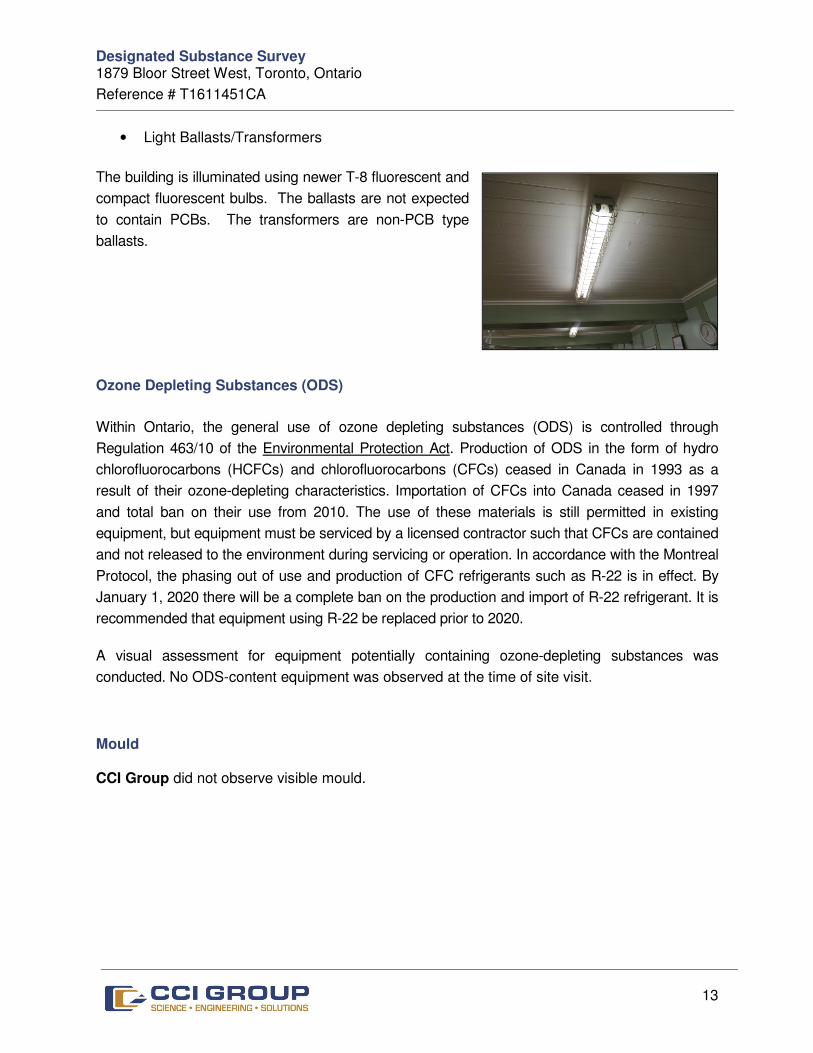
• Light Ballasts/Transformers
The building is illuminated using newer T-8 fluorescent and
compact fluorescent bulbs. The ballasts are not expected
to contain PCBs. The transformers are non-PCB type
ballasts.
Ozone Depleting Substances (ODS)
Within Ontario, the general use of ozone depleting substances (ODS) is controlled through
Regulation 463/10 of the Environmental Protection Act. Production of ODS in the form of hydro
chlorofluorocarbons (HCFCs) and chlorofluorocarbons (CFCs) ceased in Canada in 1993 as a
result of their ozone-depleting characteristics. Importation of CFCs into Canada ceased in 1997
and total ban on their use from 2010. The use of these materials is still permitted in existing
equipment, but equipment must be serviced by a licensed contractor such that CFCs are contained
and not released to the environment during servicing or operation. In accordance with the Montreal
Protocol, the phasing out of use and production of CFC refrigerants such as R-22 is in effect. By
January 1, 2020 there will be a complete ban on the production and import of R-22 refrigerant. It is
recommended that equipment using R-22 be replaced prior to 2020.
A visual assessment for equipment potentially containing ozone-depleting substances was
conducted. No ODS-content equipment was observed at the time of site visit.
Mould
CCI Group did not observe visible mould.
Designated Substance Survey 1879 Bloor Street West, Toronto, Ontario
Reference # T1611451CA
14
6.0 CONCLUSIONS AND RECOMMENDATIONS
On the basis of our investigations, representative sampling and laboratory analysis of suspected
asbestos and lead containing materials, as well as mould-affected materials; the following
conclusions and recommendations are presented:
Lead
Maintain paint finishes in good condition. Provide water testing to confirm the presence of lead
in the water.
Mercury
Maintain fluorescent fixtures and dispose of as per Ontario Regulations 844 and 347. Based on
limited quantities, costs are not carried in this review.
Silica
Precautions should be taken as required during major renovations and demolition projects on
concrete (i.e. coring through concrete slabs, demolition of masonry, etc.) to ensure that workers’
exposure levels to airborne silica does not exceed 0.05 mg/m3.
This can be achieved by:
• providing the workers with respiratory protection;
• wetting the surface of the materials to prevent dust emissions; and,
• providing workers with facilities to properly wash prior to exiting the work area.
• Demolition work that is likely to impact silica-containing materials should be carried out
in accordance with the requirement detailed in the Ontario Ministry of Labour document
entitled “Guideline: Silica on Construction Projects”, dated September 2004.
Other Designated Substances
Other Designated Substances (acrylonitrile, arsenic, coke oven emissions, ethylene oxide,
isocyanates, benzene or vinyl chloride) are not expected to be present in the building in matrix
form or of sufficient quantity to cause an exceedance of Ministry of Labour exposure guidelines.

Designated Substance Survey 1879 Bloor Street West, Toronto, Ontario
Reference # T1611451CA
15
7.0 GENERAL CONSIDERATIONS AND LIMITATIONS
The information presented in this report is based on information provided by others, direct visual
observation made by personnel with CCI, and the results of laboratory testing as identified herein.
It should be noted that there might be hazardous materials in locations not visible during our
investigation. Prior to any demolition/dismantling of materials additional testing is
recommended as a means of worker and occupant protection.
The findings detailed in this report are based upon the information available at the time of
preparation of the report. No investigative method eliminates the possibility of obtaining
imprecise or incomplete information. Professional judgement was exercised in gathering and
analyzing the information obtained and in the formulation of our conclusions and
recommendations.
CCI does not certify or warrant the environmental status of the property nor the building on the
property.
Please note that the passage of time affects the information provided in the report.
Environmental conditions of a site can change. Opinions relating to the site conditions are based
upon information that existed at the time that the conclusions were formulated.
The client expressly agrees that it has entered into this agreement with CCI, both on its own
behalf and as agent on behalf of its employees and principals.
The client expressly agrees that CCI’s employees and principals shall have no personal liability
to the client in respect of a claim, whether in contract, tort and/or any other cause of action in
law. Accordingly, the client expressly agrees that it will bring no proceedings and take no action
in any court of law against any of CCI’s employees or principals in their personal capacity.

Designated Substance Survey 1879 Bloor Street West, Toronto, Ontario
Reference # T1611451CA
16
We trust that we have detailed our findings clearly and that we have satisfactorily addressed the
scope of work you require at this time. In the event you wish us to review our findings with us,
or require our services further in this regard, please do not hesitate to contact our office.
Sincerely,
CCI GROUP INC.
Prepared by:
John Kirkpatrick, B.Tech.(Arch.Sc.), M.A.A.T.O., CRP, BCQ
Director, Corporate Projects
APPENDIX A – LAB ANALYSIS
Order #: 1639112
Project Description: City of Toronto - High Park Chess Club
Certificate of Analysis
Client:
Report Date: 22-Sep-2016
Order Date: 20-Sep-2016
Client PO: T1611451CA
CCI Group Inc.
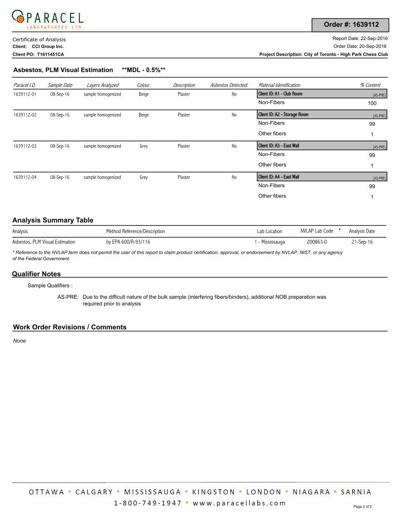
Asbestos, PLM Visual Estimation **MDL - 0.5%**
Paracel I.D. Material IdentificationSample Date % ContentLayers Analyzed Colour Description Asbestos Detected:
1639112-01 Client ID: A1 - Club Room08-Sep-16 [AS-PRE]sample homogenized Beige Plaster No
100Non-Fibers
1639112-02 Client ID: A2 - Storage Room08-Sep-16 [AS-PRE]sample homogenized Beige Plaster No
99Non-Fibers
1Other fibers
1639112-03 Client ID: A3 - East Wall08-Sep-16 [AS-PRE]sample homogenized Grey Plaster No
99Non-Fibers
1Other fibers
1639112-04 Client ID: A4 - East Wall08-Sep-16 [AS-PRE]sample homogenized Grey Plaster No
99Non-Fibers
1Other fibers
Analysis Summary Table
Analysis Method Reference/Description Analysis DateLab Location NVLAP Lab Code *
21-Sep-16200863-01 - Mississaugaby EPA 600/R-93/116Asbestos, PLM Visual Estimation
* Reference to the NVLAP term does not permit the user of this report to claim product certification, approval, or endorsement by NVLAP, NIST, or any agency
of the Federal Government.
Qualifier Notes
Sample Qualifiers :
Due to the difficult nature of the bulk sample (interfering fibers/binders), additional NOB preparation was
required prior to analysis
:AS-PRE
Work Order Revisions / Comments
None
Page 2 of 2
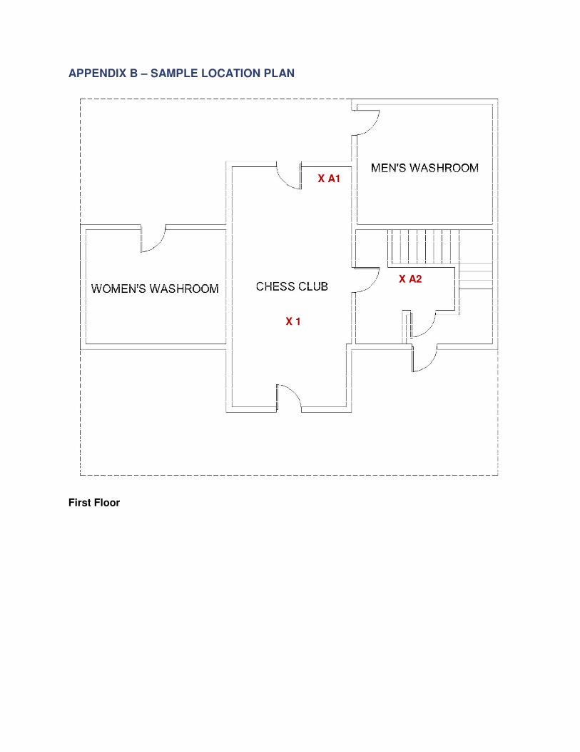
APPENDIX B – SAMPLE LOCATION PLAN
First Floor
X 1
X A1
X A2
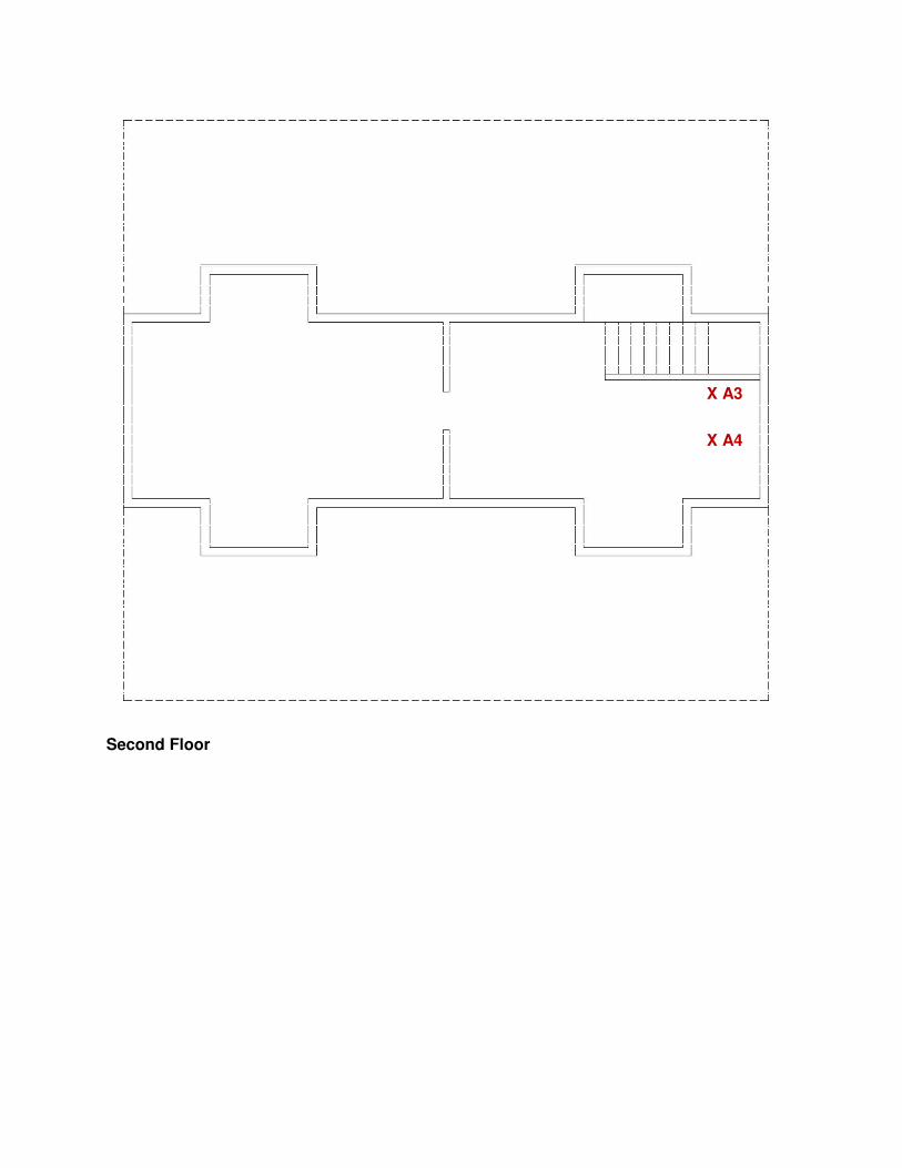
Second Floor
X A3
X A4

REPORT ON
GEOTECHNICAL INVESTIGATION
PROPOSED INTERIOR ALTERATIONS AND RETROFIT CONSTRUCTION
CHESS HOUSE CLUB, HIGH PARK, 1879 BLOOR ST
TORONTO, ONTARIO
Prepared for:
CITY OF TORONTO
Prepared By:
SIRATI & PARTNERS CONSULTANTS LTD.
Project: SP19-557-10 12700 Keele Street, King City January 21, 2020 Ontario L7B 1H5 Tel: 905.833.1582 Fax: 905.833.5360
Project: SP19-557-10 Geotechnical Investigation Report City of Toronto Proposed Interior Alteration and Retrofit Construction 1879 Bloor Street, Toronto, Ontario
SIRATI & PARTNERS CONSULTANTS LIMITED i
January 21, 2020
TABLE OF CONTENTS
1.0 INTRODUCTION 1
2.0 FIELD AND LABORATORY WORK 2
3.0 SITE AND SUBSURFACE CONDITIONS 2
3.1 SOIL CONDITIONS ........................................................................................................ 2
3.2 GROUNDWATER CONDITIONS ................................................................................. 3
4.0 DISCUSSION AND RECOMMENDATIONS 3
4.1. FOUNDATIONS ............................................................................................................... 3
5.0. EARTHQUAKE CONSIDERATIONS 5
6.0. GENERAL COMMENTS ON REPORT 5
DRAWINGS NO.
BOREHOLES LOCATION PLAN 1
NOTES ON SAMPLE DESCRIPTIONS 1A
BOREHOLE LOGS 2-3
GRADATION CURVE 4
APPENDIX A: LIMITATIONS OF REPORT

Project: SP19-557-10 Geotechnical Investigation Report City of Toronto Proposed Interior Alteration and Retrofit Construction 1879 Bloor Street, Toronto, Ontario
SIRATI & PARTNERS CONSULTANTS LIMITED 1
January 21, 2020
1.0 INTRODUCTION
Sirati & Partners Consultants Ltd. (SIRATI) was retained by City of Toronto (the Client or the City) to
undertake a geotechnical investigation for the interior alteration and retrofit construction of the chess
house club within the High Park located at 1879 Bloor Street in Toronto, Ontario (the site or subject
site).
It is understood that the client intends to conduct the interior alteration and retrofit construction of the
existing chess house club building within the High Park located at 1879 Bloor Street in Toronto,
Ontario. The development is proposed to include construction addition of new structural members
inside the chess house club building.
The Existing Basement Floor Plan showing borehole locations, titled “Soil Test Location”, dated
October 26, 2019, prepared by Carvajal Structural Engineer was provided to SIRATI.
The site is currently occupied with a two-storey clubhouse building with a basement level. The Chess
House Club has historical value. The subject site is located within the High Park with a Civic address
of 1879 Bloor Street in Toronto.
The purpose of the geotechnical investigation was to determine the subsurface conditions at two (2)
interior borehole locations (client’s specification) and from the findings in the boreholes, make
geotechnical engineering recommendations for the soil bearing capacity of native soil and earthquake
consideration.
This report is geotechnical in nature and only deals with geotechnical issues pertinent to the site and
proposed development. At the time of preparation of this report, no information regarding the existing
footing characteristics (i.e. depth, width, and type) were provided.
This report is provided on the basis of the terms of reference presented above and, on the assumption,
that the design will be in accordance with the applicable codes and standards. If there are any changes
in the design features relevant to the geotechnical analyses, or if any questions arise concerning the
geotechnical aspects of the codes and standards, this office should be contacted to review the design. It
may then be necessary to carry out additional borings and reporting before the recommendations of this
office can be relied upon.
The site investigation and recommendations follow generally accepted practice for geotechnical
consultants in Ontario. The format and contents are guided by client specific needs and economics and
do not conform to generalized standards for services. Laboratory testing for most part follows ASTM
or CSA Standards or modifications of these standards that have become standard practice.
This report has been prepared for City of Toronto (the Client) and its designers. Third party use of this
report without Sirati & Partners Consultants Limited (SIRATI) consent is prohibited. The limitation

Project: SP19-557-10 Geotechnical Investigation Report City of Toronto Proposed Interior Alteration and Retrofit Construction 1879 Bloor Street, Toronto, Ontario
SIRATI & PARTNERS CONSULTANTS LIMITED 2
January 21, 2020
conditions presented in Appendix A form an integral part of the report and they must be considered in
conjunction with this report.
2.0 FIELD AND LABORATORY WORK
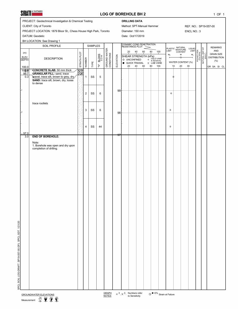
Two (2) interior boreholes (BH1 and BH2, see Drawing 1 for borehole location plan) were drilled at
the site to a maximum depth of 3.0 m below existing basement floor slab level. The boreholes were
drilled by conducting manual sampling (half weight) equipment by a drilling sub-contractor under the
direction and full-time supervision of SIRATI personnel. Samples were retrieved with a 50 mm O.D.
split-barrel sampler driven with a hammer weighing 312 N and dropping 760 mm in accordance with
the Standard Penetration Test (SPT) method. SPT Blow count numbers are to be corrected by 0.5 factor
due half weight hammer. The samples were logged in the field and returned to the SIRATI laboratory
for detailed examination by the project engineer and for laboratory testing.
As well as visual examination in the laboratory, all the soil samples were tested for moisture content.
One (1) representative soil sample was subjected to grain size and hydrometer analyses and gradation
curve is presented in Drawing No. 4 and on respective borehole log. The existing basement floor slab
elevation was assumed as 100.0 m (local).
3.0 SITE AND SUBSURFACE CONDITIONS
The borehole locations are shown on Drawing 1. Notes on sample descriptions and the general features
of fill material and glacial till are presented on Drawing 1A. Detailed subsurface conditions are
presented on the Borehole Logs, Drawings 2 and 3. The soil and groundwater conditions are
summarized as follows:
3.1 Soil Conditions
Concrete Floor Slab: Initially a 65 mm thick concrete floor slab was encountered overlaying the
granular fill material. The thickness of granular material consisting of sand, trace gravel was found to
be approximately 300 mm. The thickness of concrete and granular material is presented in the
respective borehole logs. It should be noted that the thickness of the concrete and granular material
explored at the borehole location may not be representative of the entire basement floor slab area.
Cohesionless Soil: Native, cohesionless soil deposit consisting of sand to silty sand was encountered
directly underneath the granular fill material. The soil deposit was extended to a depth of approximately
3.0 m, end of the borehole, below the existing floor slab. The measured SPT ‘N’ values in cohesionless
soil deposit ranged from 2 to above 50 blows per 300 mm of sampler penetration, indicating very loose
to very dense condition.
One (1) representative sample of the cohesionless soil (BH1/SS4) was subjected to grain size analysis.
Gradation curve is presented on Drawing 4. The soil fractions are summarized below:
Project: SP19-557-10 Geotechnical Investigation Report City of Toronto Proposed Interior Alteration and Retrofit Construction 1879 Bloor Street, Toronto, Ontario
SIRATI & PARTNERS CONSULTANTS LIMITED 3
January 21, 2020
Clay: 6%
Silt: 23%
Sand: 70%
Gravel: 1%
3.2 Groundwater Conditions
During drilling, no ground water was observed in the boreholes. It should be noted that the groundwater
levels can vary and subject to seasonal fluctuation in response to major weather events.
4.0 DISCUSSION AND RECOMMENDATIONS
It is understood that the Client is intended to conduct the interior alteration and retrofit construction of
the Chess House Club within the High Park located at 1879 Bloor Street in Toronto.
The following recommendation should be considered as preliminary and will need to be re-assessed by
SIRATI once the architectural and structural designs are provided.
4.1. FOUNDATIONS
At the time of preparation of this report, design loading requirements have not been made available.
Based on our understanding, the footings for the proposed new structural elements may be supported
by conventional spread/strip footings.
In Toronto Area, all footings exposed to seasonal freezing conditions must be buried at a minimum
depth of 1.2 m below the ground surface for frost protection.
4.1.1 Conventional Strip/Spread Foundation
Based on the soil resistance values at the borehole location. The foundation for the new structural
elements for interior alteration and retrofit construction of Clubhouse Building can be supported by
conventional strip/spread footings.
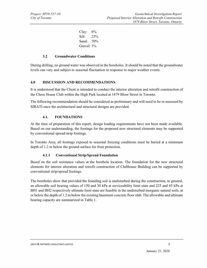
The boreholes show that provided the founding soil is undisturbed during the construction, in general,
an allowable soil bearing values of 150 and 30 kPa at serviceability limit state and 225 and 45 kPa at
BH1 and BH2 respectively ultimate limit state are feasible in the undisturbed inorganic natural soils, at
or below the depth of 1.2 m below the existing basement concrete floor slab. The allowable and ultimate
bearing capacity are summarized in Table 1.
Project: SP19-557-10 Geotechnical Investigation Report City of Toronto Proposed Interior Alteration and Retrofit Construction 1879 Bloor Street, Toronto, Ontario
SIRATI & PARTNERS CONSULTANTS LIMITED 4
January 21, 2020
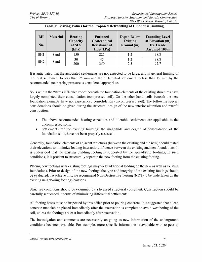
Table 1: Bearing Values for the Proposed Retrofitting of Clubhouse Building
BH
No.
Material
Bearing Capacity at SLS (kPa)
Factored Geotechnical Resistance at
ULS (kPa)
Depth Below Existing
Ground (m)
Founding Level at Elevation (m)
Ex. Grade Assumed 100m
BH1 Sand 150 225 1.2 98.8
BH2 Sand 30 200
45 350
1.2 2.3
98.8 97.7
It is anticipated that the associated settlements are not expected to be large, and in general limiting of
the total settlement to less than 25 mm and the differential settlement to less than 19 mm by the
recommended net bearing pressure is considered appropriate.
Soils within the “stress influence zone” beneath the foundation elements of the existing structures have
largely completed their consolidation (compressed soil). On the other hand, soils beneath the new
foundation elements have not experienced consolidation (uncompressed soil). The following special
considerations should be given during the structural design of the new interior alteration and retrofit
construction.
The above recommended bearing capacities and tolerable settlements are applicable to the
uncompressed soils.
Settlements for the existing building, the magnitude and degree of consolidation of the
foundation soils, have not been properly assessed.
Generally, foundation elements of adjacent structures (between the existing and the new) should match
their elevations to minimize loading interaction/influence between the existing and new foundations. It
is understood that the existing building footing is supported by the spread/strip footings, in such
conditions, it is prudent to structurally separate the new footing from the existing footing.
Placing new footings near existing footings may yield additional loading on the new as well as existing
foundations. Prior to design of the new footings the type and integrity of the existing footings should
be evaluated. To achieve this, we recommend Non-Destructive Testing (NDT) to be undertaken on the
existing neighboring footings/caissons.
Structure conditions should be examined by a licensed structural consultant. Construction should be
carefully sequenced in terms of minimizing differential settlements.
All footing bases must be inspected by this office prior to pouring concrete. It is suggested that a lean
concrete mat slab be placed immediately after the excavation is complete to avoid weathering of the
soil, unless the footings are cast immediately after excavation.
The investigation and comments are necessarily on-going as new information of the underground
conditions becomes available. For example, more specific information is available with respect to


Project: SP19-557-10 Geotechnical Investigation Report City of Toronto Proposed Interior Alteration and Retrofit Construction 1879 Bloor Street, Toronto, Ontario
SIRATI & PARTNERS CONSULTANTS LIMITED
January 21, 2020
Drawings
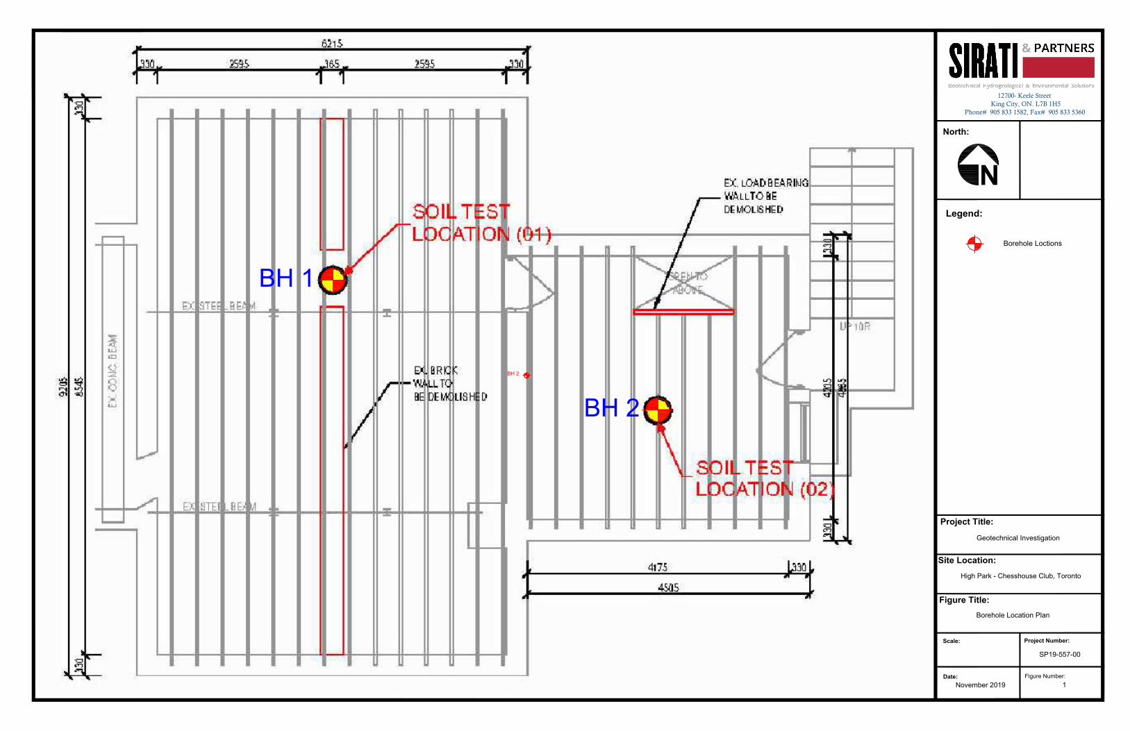
BH 1
BH 2
BH 2
Legend:
Project Title:
North:
Site Location:
Figure Title:
Scale:Project Number:
Figure Number:
Date:
Geotechnical Investigation
Borehole Location Plan
1
12700- Keele Street King City, ON. L7B 1H5
Phone# 905 833 1582, Fax# 905 833 5360
November 2019
High Park - Chesshouse Club, Toronto
SP19-557-00
N
Borehole Loctions
Project: SP19-557-10 Geotechnical Investigation Report City of Toronto Proposed Interior Alteration and Retrofit Construction 1879 Bloor Street, Toronto, Ontario
SIRATI & PARTNERS CONSULTANTS LIMITED
January 21, 2020
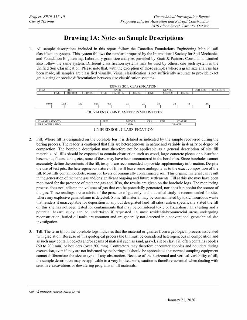
Drawing 1A: Notes on Sample Descriptions
1. All sample descriptions included in this report follow the Canadian Foundations Engineering Manual soil classification system. This system follows the standard proposed by the International Society for Soil Mechanics and Foundation Engineering. Laboratory grain size analyses provided by Sirati & Partners Consultants Limited also follow the same system. Different classification systems may be used by others; one such system is the Unified Soil Classification. Please note that, with the exception of those samples where a grain size analysis has been made, all samples are classified visually. Visual classification is not sufficiently accurate to provide exact grain sizing or precise differentiation between size classification systems.
ISSMFE SOIL CLASSIFICATION CLAY SILT SAND GRAVEL COBBLES BOULDERS
FINE MEDIUM COARSE FINE MEDIUM COARSE FINE MEDIUM COARSE
0.002 0.006 0.02 0.06 0.2 0.6 2.0 6.0 20 60 200
EQUIVALENT GRAIN DIAMETER IN MILLIMETRES
CLAY (PLASTIC) TO FINE MEDIUM CRS. FINE COARSE
SILT (NONPLASTIC) SAND GRAVEL
UNIFIED SOIL CLASSIFICATION
2. Fill: Where fill is designated on the borehole log it is defined as indicated by the sample recovered during the boring process. The reader is cautioned that fills are heterogeneous in nature and variable in density or degree of compaction. The borehole description may therefore not be applicable as a general description of site fill materials. All fills should be expected to contain obstruction such as wood, large concrete pieces or subsurface basements, floors, tanks, etc., none of these may have been encountered in the boreholes. Since boreholes cannot accurately define the contents of the fill, test pits are recommended to provide supplementary information. Despite the use of test pits, the heterogeneous nature of fill will leave some ambiguity as to the exact composition of the fill. Most fills contain pockets, seams, or layers of organically contaminated soil. This organic material can result in the generation of methane gas and/or significant ongoing and future settlements. Fill at this site may have been monitored for the presence of methane gas and, if so, the results are given on the borehole logs. The monitoring process does not indicate the volume of gas that can be potentially generated, nor does it pinpoint the source of the gas. These readings are to advise of the presence of gas only, and a detailed study is recommended for sites where any explosive gas/methane is detected. Some fill material may be contaminated by toxic/hazardous waste that renders it unacceptable for deposition in any but designated land fill sites; unless specifically stated the fill on this site has not been tested for contaminants that may be considered toxic or hazardous. This testing and a potential hazard study can be undertaken if requested. In most residential/commercial areas undergoing reconstruction, buried oil tanks are common and are generally not detected in a conventional geotechnical site investigation.
3. Till: The term till on the borehole logs indicates that the material originates from a geological process associated with glaciation. Because of this geological process the till must be considered heterogeneous in composition and as such may contain pockets and/or seams of material such as sand, gravel, silt or clay. Till often contains cobbles (60 to 200 mm) or boulders (over 200 mm). Contractors may therefore encounter cobbles and boulders during excavation, even if they are not indicated by the borings. It should be appreciated that normal sampling equipment cannot differentiate the size or type of any obstruction. Because of the horizontal and vertical variability of till, the sample description may be applicable to a very limited zone; caution is therefore essential when dealing with sensitive excavations or dewatering programs in till materials.
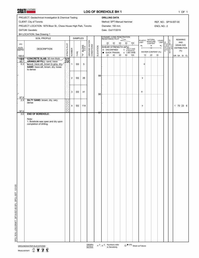
CONCRETE SLAB: 50 mm thickGRANULAR FILL: sand, tracegravel, trace silt, brown to grey, drySAND: trace silt, brown, dry, looseto dense
SILTY SAND: brown, dry, verydense
END OF BOREHOLE:
Note:1. Borehole was open and dry uponcompletion of drilling.
6
5
26
41
114 1
0.1
0.3
2.3
3.0
SS
SS
SS
SS
1
2
3
4 70
100.099.7
97.8
97.0
23
LOG OF BOREHOLE BH 1
1st 2nd 4th3rd
GROUNDWATER ELEVATIONS
(kN
/m3 )
SOIL PROFILE
wL
0.0
UNCONFINED
1 OF 1
20 40 60 80 100GR
OU
ND
WA
TE
R
CO
ND
ITIO
NS
"N"
B
LOW
S
0.3
m
DESCRIPTION
GR
NA
TU
RA
L U
NIT
WT
PO
CK
ET
PE
N.
100.0
PLASTICLIMIT
FIELD VANE& Sensitivity
ELEV
DYNAMIC CONE PENETRATIONRESISTANCE PLOT
20 40 60 80 100
QUICK TRIAXIAL
SHEAR STRENGTH (kPa)
TY
PE
,3
CL
=3%Strain at Failure
Measurement
1
2
3
Numbers referto Sensitivity
w
ELE
VA
TIO
N
:
10 20 30
REMARKS
AND
GRAIN SIZE
DISTRIBUTION
(%)
NATURALMOISTURECONTENT
3
SI
GRAPHNOTES
PROJECT: Geotechnical Investigation & Chemical Testing
CLIENT: City of Toronto
PROJECT LOCATION: 1879 Bloor St., Chess House High Park, Toronto
DATUM: Geodetic
BH LOCATION: See Drawing 1
LIQUIDLIMIT
SAMPLES
NU
MB
ER
99
98
97
(Cu)
(kP
a)(m)
ST
RA
TA
PLO
T
LAB VANE WATER CONTENT (%)
wP
DEPTH
SA
DRILLING DATA
Method: SPT-Manual Hammer
Diameter: 150 mm
Date: Oct/17/2019
REF. NO.: SP19-557-00
ENCL NO.: 2
SP
CL
SO
IL L
OG
-DR
AF
T S
P19
-557
-00.
GP
J S
PC
L.G
DT
1/2
1/20
CONCRETE SLAB: 50 mm thickGRANULAR FILL: sand, tracegravel, trace silt, brown to grey, drySAND: trace silt, brown, dry, looseto dense
trace rootlets
END OF BOREHOLE:
Note:1. Borehole was open and dry uponcompletion of drilling.
5
6
6
44
0.1
0.3
3.0
SS
SS
SS
SS
1
2
3
4
100.099.7
97.0
LOG OF BOREHOLE BH 2
1st 2nd 4th3rd
GROUNDWATER ELEVATIONS
(kN
/m3 )
SOIL PROFILE
wL
0.0
UNCONFINED
1 OF 1
20 40 60 80 100GR
OU
ND
WA
TE
R
CO
ND
ITIO
NS
"N"
B
LOW
S
0.3
m
DESCRIPTION
GR
NA
TU
RA
L U
NIT
WT
PO
CK
ET
PE
N.
100.0
PLASTICLIMIT
FIELD VANE& Sensitivity
ELEV
DYNAMIC CONE PENETRATIONRESISTANCE PLOT
20 40 60 80 100
QUICK TRIAXIAL
SHEAR STRENGTH (kPa)
TY
PE
,3
CL
=3%Strain at Failure
Measurement
1
2
3
Numbers referto Sensitivity
w
ELE
VA
TIO
N
:
10 20 30
REMARKS
AND
GRAIN SIZE
DISTRIBUTION
(%)
NATURALMOISTURECONTENT
3
SI
GRAPHNOTES
PROJECT: Geotechnical Investigation & Chemical Testing
CLIENT: City of Toronto
PROJECT LOCATION: 1879 Bloor St., Chess House High Park, Toronto
DATUM: Geodetic
BH LOCATION: See Drawing 1
LIQUIDLIMIT
SAMPLES
NU
MB
ER
99
98
97
(Cu)
(kP
a)(m)
ST
RA
TA
PLO
T
LAB VANE WATER CONTENT (%)
wP
DEPTH
SA
DRILLING DATA
Method: SPT-Manual Hammer
Diameter: 150 mm
Date: Oct/17/2019
REF. NO.: SP19-557-00
ENCL NO.: 3
SP
CL
SO
IL L
OG
-DR
AF
T S
P19
-557
-00.
GP
J S
PC
L.G
DT
1/2
1/20

Project No. :
Date :
Figure No. : 4
GRAIN SIZE DISTRIBUTION
04 November 2019
SP19-557-10
0
10
20
30
40
50
60
70
80
90
100
0.001 0.01 0.1 1 10 100
PER
CEN
T
PA
SSIN
G
GRAIN SIZE ( mm )
19S0835 BH1-SS4
CLAY AND SILTSAND GRAVEL
Fine CoarseFine Medium Coarse
1 5 13/4"1/#4#16
#200#50#100
GRAIN SIZE IN MICROMETERS753
SIEVE DESIGNATION ( Imperial )
3/8"
UNIFIED SOIL CLASSIFICATION SYSTEM
3"
Project: SP19-557-10 Geotechnical Investigation Report City of Toronto Proposed Interior Alteration and Retrofit Construction 1879 Bloor Street, Toronto, Ontario
SIRATI & PARTNERS CONSULTANTS LIMITED
January 21, 2020
Appendix A: Limitations of Report
This report is intended solely for the Client named. The material in it reflects our best judgment in light of the information available to Sirati & Partners Consultants Limited (SIRATI) at the time of preparation. Unless otherwise agreed in writing by SIRATI, it shall not be used to express or imply warranty as to the fitness of the property for a particular purpose. No portion of this report may be used as a separate entity, it is written to be read in its entirety.
The conclusions and recommendations given in this report are based on information determined at the borehole locations. The information contained herein in no way reflects on the environment aspects of the project, unless otherwise stated. Subsurface and groundwater conditions between and beyond the boreholes may differ from those encountered at the borehole locations, and conditions may become apparent during construction, which could not be detected or anticipated at the time of the site investigation. The benchmark and elevations used in this report are primarily to establish relative elevation differences between the borehole locations and should not be used for other purposes, such as grading, excavating, planning, development, etc. Professional judgement was exercised in gathering and analyzing data and formulation of recommendations using current industry guidelines and standards. Similar to all professional persons rendering advice, SIRATI cannot act as absolute insurer of the conclusion we have reached. No additional warranty or representation, expressed or implied, is included or intended in this report other than stated herein the report.
The design recommendations given in this report are applicable only to the project described in the text and then only if constructed substantially in accordance with the details stated in this report.
The comments made in this report on potential construction problems and possible methods are intended only for the guidance of the designer. The number of boreholes may not be sufficient to determine all the factors that may affect construction methods and costs. For example, the thickness of surficial topsoil or fill layers may vary markedly and unpredictably. The contractors bidding on this project or undertaking the construction should, therefore, make their own interpretation of the factual information presented and draw their own conclusions as to how the subsurface conditions may affect their work. This work has been undertaken in accordance with normally accepted geotechnical engineering practices.
Any use which a third party makes of this report, or any reliance on or decisions to be made based on it, are the responsibility of such third parties. SIRATI accepts no responsibility for damages, if any, suffered by any third party as a result of decisions made or actions based on this report.
We accept no responsibility for any decisions made or actions taken as a result of this report unless we are specifically advised of and participate in such action, in which case our responsibility will be as agreed to at that time. Any user of this report specifically denies any right to claims against the Consultant, Sub-Consultants, their officers, agents and employees in excess of the fee paid for professional services.
SIRATI engagement hereunder is subject to and condition upon, that SIRATI not being required by the Client, or any other third party to provide evidence or testimony in any legal proceedings pertaining to this finding of this report or providing litigations support services which may arise to be required in respect of the work produced herein by SIRATI. It is prohibited to publish, release or disclose to any third party the report produced by SIRATI pursuant to this engagement and such report is produced solely for the Client own internal purposes and which shall remain the confidential proprietary property of SIRATI for use by the Client, within the context of the work agreement. The Client will and does hereby remise and forever absolutely release SIRATI, its directors, officers, agents and shareholders of and from any and all claims, obligations, liabilities, expenses, costs, charges or other demands or requirements of any nature pertaining to the report produced by SIRATI hereunder. The Client will not commence any claims against any Person who may make a claim against SIRATI in respect of work produced under this engagement.
SECTION 01 10 00 SCOPE OF WORK 1879 BLOOR STREET WEST | HIGH PARK CHESS HOUSE RENOVATIONS
PAGE 01 10 00.1 JANUARY 2020
CHERIE NG ARCHITECT INC. Project 1911
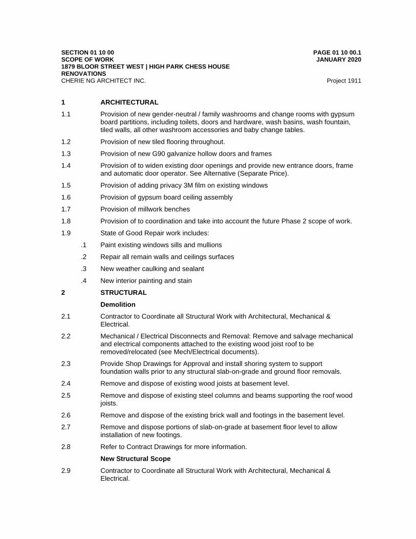
1 ARCHITECTURAL
1.1 Provision of new gender-neutral / family washrooms and change rooms with gypsum board partitions, including toilets, doors and hardware, wash basins, wash fountain, tiled walls, all other washroom accessories and baby change tables.
1.2 Provision of new tiled flooring throughout.
1.3 Provision of new G90 galvanize hollow doors and frames
1.4 Provision of to widen existing door openings and provide new entrance doors, frame and automatic door operator. See Alternative (Separate Price).
1.5 Provision of adding privacy 3M film on existing windows
1.6 Provision of gypsum board ceiling assembly
1.7 Provision of millwork benches
1.8 Provision of to coordination and take into account the future Phase 2 scope of work.
1.9 State of Good Repair work includes:
.1 Paint existing windows sills and mullions
.2 Repair all remain walls and ceilings surfaces
.3 New weather caulking and sealant
.4 New interior painting and stain
2 STRUCTURAL
Demolition
2.1 Contractor to Coordinate all Structural Work with Architectural, Mechanical & Electrical.
2.2 Mechanical / Electrical Disconnects and Removal: Remove and salvage mechanical and electrical components attached to the existing wood joist roof to be removed/relocated (see Mech/Electrical documents).
2.3 Provide Shop Drawings for Approval and install shoring system to support foundation walls prior to any structural slab-on-grade and ground floor removals.
2.4 Remove and dispose of existing wood joists at basement level.
2.5 Remove and dispose of existing steel columns and beams supporting the roof wood joists.
2.6 Remove and dispose of the existing brick wall and footings in the basement level.
2.7 Remove and dispose portions of slab-on-grade at basement floor level to allow installation of new footings.
2.8 Refer to Contract Drawings for more information.
New Structural Scope
2.9 Contractor to Coordinate all Structural Work with Architectural, Mechanical & Electrical.
SECTION 01 10 00 SCOPE OF WORK 1879 BLOOR STREET WEST | HIGH PARK CHESS HOUSE RENOVATIONS
PAGE 01 10 00.2 JANUARY 2020
CHERIE NG ARCHITECT INC. Project 1911
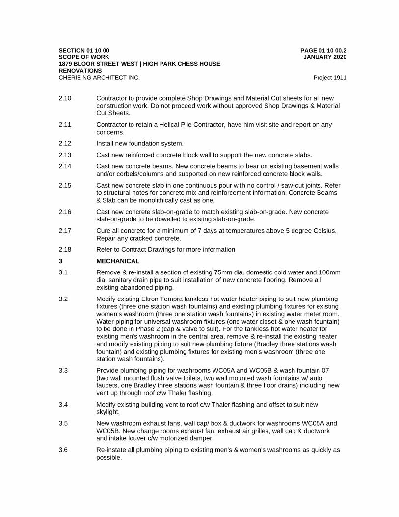
2.10 Contractor to provide complete Shop Drawings and Material Cut sheets for all new construction work. Do not proceed work without approved Shop Drawings & Material Cut Sheets.
2.11 Contractor to retain a Helical Pile Contractor, have him visit site and report on any concerns.
2.12 Install new foundation system.
2.13 Cast new reinforced concrete block wall to support the new concrete slabs.
2.14 Cast new concrete beams. New concrete beams to bear on existing basement walls and/or corbels/columns and supported on new reinforced concrete block walls.
2.15 Cast new concrete slab in one continuous pour with no control / saw-cut joints. Refer to structural notes for concrete mix and reinforcement information. Concrete Beams & Slab can be monolithically cast as one.
2.16 Cast new concrete slab-on-grade to match existing slab-on-grade. New concrete slab-on-grade to be dowelled to existing slab-on-grade.
2.17 Cure all concrete for a minimum of 7 days at temperatures above 5 degree Celsius. Repair any cracked concrete.
2.18 Refer to Contract Drawings for more information
3 MECHANICAL
3.1 Remove & re-install a section of existing 75mm dia. domestic cold water and 100mm dia. sanitary drain pipe to suit installation of new concrete flooring. Remove all existing abandoned piping.
3.2 Modify existing Eltron Tempra tankless hot water heater piping to suit new plumbing fixtures (three one station wash fountains) and existing plumbing fixtures for existing women's washroom (three one station wash fountains) in existing water meter room. Water piping for universal washroom fixtures (one water closet & one wash fountain) to be done in Phase 2 (cap & valve to suit). For the tankless hot water heater for existing men's washroom in the central area, remove & re-install the existing heater and modify existing piping to suit new plumbing fixture (Bradley three stations wash fountain) and existing plumbing fixtures for existing men's washroom (three one station wash fountains).
3.3 Provide plumbing piping for washrooms WC05A and WC05B & wash fountain 07 (two wall mounted flush valve toilets, two wall mounted wash fountains w/ auto faucets, one Bradley three stations wash fountain & three floor drains) including new vent up through roof c/w Thaler flashing.
3.4 Modify existing building vent to roof c/w Thaler flashing and offset to suit new skylight.
3.5 New washroom exhaust fans, wall cap/ box & ductwork for washrooms WC05A and WC05B. New change rooms exhaust fan, exhaust air grilles, wall cap & ductwork and intake louver c/w motorized damper.
3.6 Re-instate all plumbing piping to existing men's & women's washrooms as quickly as possible.
SECTION 01 10 00 SCOPE OF WORK 1879 BLOOR STREET WEST | HIGH PARK CHESS HOUSE RENOVATIONS
PAGE 01 10 00.3 JANUARY 2020
CHERIE NG ARCHITECT INC. Project 1911
3.7 Electrical trade to provide all new electric heaters & thermostats. Provide all required plumbing pressure test, flushing & disinfection of the new domestic water line, air balancing and all reports.
4 ELECTRICAL
4.1 Demolition of existing interior lighting fixtures, switches, receptacles, electric heating and controls, destratification fan power connection and associated wiring throughout the building (excluding the two existing public washrooms) and disposal to scrap.
4.2 Provision of new interior lighting fixtures, switches, receptacles, electric heating and controls, exhaust fan power connections, electric hand dryers and associated new wiring to accommodate the building alteration and renovation.
4.3 New lighting fixtures to be energy-efficient LED type.
4.4 Disconnection and removal of power wiring to electric unit heaters and on-demand domestic water heaters (in basement) to accommodate the renovation.
4.5 Disconnection and removal of power wiring for the two existing public washrooms (at the basement level) to accommodate the renovation.
4.6 Provision of new wiring to restore power to existing electric heaters and on-demand domestic water heaters in basement.
4.7 Provision of new wiring at the basement level to restore power to the two existing public washrooms.
4.8 Provision of occupancy sensors to control all lighting on ground and 2nd floors.
4.9 Provision of emergency lighting remote lamp heads and battery packs and exit lights and associated wiring throughout building (excluding the two existing public washrooms).
4.10 New exit lights to be pictogram type in compliance with current building code requirements.
4.11 Replacement of existing service-entrance panel board with a new larger panel to accommodate additional circuits required for the renovation.
4.12 Provision of a new call for assistance system and associated wiring for the new universal washroom.
4.13 Provision of power connections for three (3) new automatic door operators and associated controls on two doors to the exterior and door to new universal washroom.
4.14 Provision of time controls for new change room exhaust fan.
4.15 Provision of controls to interlock new motorized damper for intake air with operation of new exhaust fans at the ground floor level.
4.16 Addition of photocell and time controls for existing exterior (soffit) lighting. There are no existing controls.
4.17 Work to be accomplished in two phases as requested by the client.
END OF SECTION
SECTION 01 10 10 GENERAL REQUIREMENTS 1879 BLOOR STREET WEST | HIGH PARK CHESS HOUSE RENOVATIONS
PAGE 01 10 10.1 JANUARY 2020
CHERIE NG ARCHITECT INC. Project 1911
1 GENERAL
1.1 The requirements of the Articles of Agreement, Conditions of the Contract, Division 1 apply to and form all Sections of the Contract Documents and the Work.
1.2 Work in this Specification is divided into descriptive sections which are not intended to identify absolute contractual limits between Subcontractors, nor between the Contractor and their Subcontractors. The Contractor is responsible for organizing division of labour and supply of materials essential to complete the Contract. The Consultant assumes no liability to act as an arbiter to establish subcontract limits between Sections or Divisions of Work.
1.3 It is intended that Work supplied under these Contract Documents shall be complete and fully operational in every detail for the purpose required. Provide all items, articles, materials, services and incidentals, whether or not expressly specified or shown on Drawings, to make finished Work complete and fully operational, consistent with the intent of the Contract Documents.
1.4 Work designated as “N.I.C.” is not included in this Contract.
1.5 Specifications, Schedules and Drawings are complementary and items mentioned or indicated on one may not be mentioned or indicated on the others.
1.6 Contractors finding discrepancies or ambiguities in, or omissions from the Drawings, Specifications or other Contract Documents, or having doubt as to the meaning and intent of any part thereof shall contact the Consultant for clarification. If the Consultant is not contacted for clarification, execute the Work in accordance with the most stringent requirements.
1.7 Mention in the specifications or indication on the drawings of materials, products, operations, or methods, requires that the Contractor provide each item mentioned or indicated of the quality or subject to the qualifications noted; perform according to the conditions stated in each operation prescribed; and provide labour, materials, Products, equipment and services to complete the Work.
1.8 Where the singular or masculine is used in the Contract Documents, it shall be read and construed as if the plural, feminine or neuter had been used when the context or the statement so requires and as required to complete the Work, and the rest of the sentence, clause, paragraph, or Article shall be construed as if all changes in grammar, gender or terminology thereby rendered necessary had been made.
1.9 The terms “approved”, “review”, “reviewed”, “accepted”, “acceptance”, “acceptable”, “satisfactory”, “selected”, “directed”, “instructed”, “required”, “submit”, “permitted” or similar words or phases are used in standards or elsewhere in Contract Documents, it shall be understood, that words “by (to) the Consultant” follow, unless context provides otherwise.
1.10 Where the words 'submit', 'acceptable' and 'satisfactory' are used in the Contract Documents, they shall be considered to be followed by the words 'to the Consultant' unless the context provides otherwise.
1.11 The terms “exposed” or “exposed to view” refers to surfaces that are within the line of vision of persons from any accessible viewpoint, both within and without the building.
SECTION 01 10 10 GENERAL REQUIREMENTS 1879 BLOOR STREET WEST | HIGH PARK CHESS HOUSE RENOVATIONS
PAGE 01 10 10.2 JANUARY 2020
CHERIE NG ARCHITECT INC. Project 1911
Where any part of a surface is exposed to view, all other portions of that surface shall also be considered as exposed to view.
1.12 Contractor to add The City of Toronto and Cherie Ng Architect Inc. as Additional Insured Names in the Contractor’s Commercial General Liability insurance policy.
1.13 Contractor to forward a copy of their Commercial General Liability Insurance Certificate of Insurance with the Additional Insured Names to the architect at the Pre-Construction Meeting.
2 EXISTING SITE CONDITIONS
2.1 Make a careful examination of the site, and investigate and be satisfied as to all matters relating to the nature of the Work to be undertaken, as to the means of access and egress thereto and therefrom, as to the obstacles to be met with, as to the extent of the Work to be performed, any limitations under which the work has to be executed, and any and all matters which are referred to in the Contract Documents.
2.2 Report any inconsistencies, ambiguities, discrepancies, omissions, and errors between Site conditions and Contract Documents to the Consultant prior to the commencement of Work. If inconsistencies, ambiguities, discrepancies, omissions, and errors are not reported and clarified, the most stringent requirement shall govern, as determined by the Consultant. Ensure that each Subcontractor performing work related to the site conditions has examined it so that all are fully informed on all particulars which affect the Work thereon in order that construction proceeds competently and expeditiously.
2.3 Before commencing the Work of any Section or trade, carefully examine the Work of other Sections and trades upon which it may depend, examine substrate surfaces, and report in writing to the Consultant, defects which might affect new Work. Commencement of Work shall constitute acceptance of conditions and Work of other sections, trades, and Other Contractors upon which the new Work depends. If repair of surfaces is required after commencement of specific work it shall be included in the work of the trade providing the specific system or finish.
3 CONTINUITY OF EXISTING SERVICES
3.1 Shutdowns and planning of operations that may affect Owner’s use of services shall be coordinated with and in accordance with the Owner’s written directions. Provide notice for all required interruptions to utility, heating, cooling, mechanical, electrical, and life safety systems.
3.2 Make written requests for shutdown at least 5 working days in advance, unless specifically stated herein or as otherwise instructed by the Owner.
3.3 Shutdowns shall be scheduled in advance with Owner and shutdown period shall be minimized to Owner’s convenience. Facilities in existing adjacent areas will be occupied during the Work.
3.4 Major shutdowns shall take place on weekends or at night by prior arrangement with and at no additional cost to the Owner.

SECTION 01 10 10 GENERAL REQUIREMENTS 1879 BLOOR STREET WEST | HIGH PARK CHESS HOUSE RENOVATIONS
PAGE 01 10 10.3 JANUARY 2020
CHERIE NG ARCHITECT INC. Project 1911
3.5 Minimize disruption, vibration, noise and dust to the function of existing building.
3.6 These requirements are for security reasons and for the consideration of the Owner. Requirements shall not be construed as cause for elimination or restriction of Contractor’s working schedule, claims for delay or work, nor additional cost.
4 ACCESS / PROPERTY CONSTRAINTS
4.1 Provide and maintain access facilities as may be required for access to the Work.
4.2 Minimize disruption, noise and dust to the functions of existing operational areas of existing buildings. Times of entry, routes of access and time required to complete the Work shall be arranged and scheduled in cooperation with the Owner.
4.3 Confine Work and operations of employees to limits indicated by the Contract Documents. Do not unreasonably encumber the premises with products.
4.4 Organize delivery of materials/equipment to and removal of debris and equipment from place of Work to permit continual progress of work and suitable for restricted site conditions.
4.5 Determine and make arrangement as required for loading and unloading of equipment and Products at times that will not affect public traffic flow and that will be permitted by the City of Toronto. Conform to City by-laws with regard to parking restrictions and other conditions.
4.6 Make provisions and arrangements and provide allowances if times for loading and unloading allowed by the City of Toronto are other than regular working hours.
4.7 All Products, materials and equipment required on Site shall be portable and/or size suitable for access and movement on Site and without causing damage to buildings.
4.8 Workers shall not enter existing building beyond construction areas except where required for connection or modification to existing services or other such work. Arrange such requirements with Owner prior to entering existing occupied areas.
4.9 Provide locked doors in barriers, permit access by Owner and Consultant to Work areas and to areas Contractor is responsible for.
5 SETTING OUT
5.1 Before commencing work, verify lines, levels and dimensions shown on the drawing and report discrepancies in levels or dimensions to the Consultant. Be responsible for work done prior to the receipt of the Consultant’s decision regarding reported discrepancies
6 PARKING
6.1 Parking may be permitted on Site provided it does not disrupt the performance of Work, Site safety or the movement of vehicular or pedestrian traffic and is acceptable to the Consultant and permitted by the City of Toronto.
SECTION 01 10 10 GENERAL REQUIREMENTS 1879 BLOOR STREET WEST | HIGH PARK CHESS HOUSE RENOVATIONS
PAGE 01 10 10.4 JANUARY 2020
CHERIE NG ARCHITECT INC. Project 1911
7 COORDINATION
7.1 Coordination of the Work of all Sections of the specifications as required to complete the Project is the responsibility of the Contractor.
7.2 Coordinate with removals/installations specified in other Divisions and Other Contracts.
7.3 Existing equipment shall remain in present locations unless designated otherwise. Protect from damage. Remove, store and reinstall existing fixed equipment, fixtures and components which interfere with construction and which are scheduled for relocation.
7.4 Pay particular attention to types of ceiling construction and clearances throughout, especially where recessed fixtures are required. Coordinate work with Other Contractors and Subcontractors wherever ventilation ducts or piping installations occur to ensure that conflicts are avoided.
7.5 Install ceiling mounted components in accordance with final ceiling plans. Inform Consultant of conflicting installations. Install as directed.
7.6 Install and arrange ducts, piping, tubing, conduit, equipment, fixtures, materials and products to conserve headroom and space with minimum interference and in neat, orderly and tidy arrangement. Run pipes, ducts, tubing and conduit, vertical, horizontal and square with building grid unless otherwise indicated. Install piping, ducts, and conduit as close to underside of structure as possible unless shown otherwise.
7.7 Make provision for unrestricted relocation of light fixtures to replace ceiling panels at grid spaces of the same size, without interference or restriction by items located within the ceiling space.
7.8 Where supports or openings are to be left for the installation of various parts of the Work furnish the necessary information to those concerned in ample time so that proper provision can be made for such items. Cutting, drilling and the subsequent patching required for failing to comply with this requirement shall be performed at a later date at no additional Cost to Owner.
7.9 Ensure that setting drawings, templates, and all other information necessary for the location and installation of materials, fixtures, equipment, holes, sleeves, inserts, anchors, accessories, fastenings, connections, and access panels are provided by each Section whose work requires cooperative location and installation by other Sections, and that such information is communicated to the applicable installer. Cutting, fixing and ‘making good’ of the work of other Contractors, Subcontractors and trades and making up of lost time involved in failing to comply with this requirement shall be performed at no additional Cost to Owner.
7.10 Be responsible for coordinating products supplied in metric (SI) and imperial units into the overall layout.
7.11 Properly coordinate the work of the various Sections and trades, taking into account the existing installations to assure the best arrangement of pipes, conduits, ducts and mechanical, electrical and other equipment, in the available space. Under no circumstances will any extra payment be allowed due to the failure by the Contractor to coordinate the Work. If required, in critical locations, prepare interference and/or
SECTION 01 10 10 GENERAL REQUIREMENTS 1879 BLOOR STREET WEST | HIGH PARK CHESS HOUSE RENOVATIONS
PAGE 01 10 10.5 JANUARY 2020
CHERIE NG ARCHITECT INC. Project 1911
installation drawings showing the work of the various Sections as well as the existing installation, and submit these drawings to the Consultant for review before the commencement of Work.
7.12 Coordinate with mechanical and electrical trades to ensure protecting, supporting, disconnecting, cutting off, capping, diverting, relocating or removing of existing services in areas of Work before commencement of alteration work.
7.13 In case of damage to active services or utilities, notify Consultant and respective authorities immediately and make all required repairs under direction of Consultant and respective authorities. Carry out repairs to such damaged services and utilities continuously to completion, including working beyond regular working hours
8 CUTTING AND PATCHING
8.1 Execute Work to avoid damage to other Work.
8.2 Execute cutting, fitting and patching including excavation and fill to complete the Work.
8.3 Employ appropriate trades with skilled labour to perform cutting Work.
8.4 Fit Work segments together, to integrate with penetrations through surfaces and with other Work.
8.5 Remove and replace defective and non-conforming Work.
8.6 Do any drilling, cutting, fitting, patching and finishing that may be required to make the various classes and kinds of other Work fit together in a professional and finished manner. Make watertight connections with adjoining structures
8.7 Provide openings in non-structural elements of Work for penetrations of mechanical and electrical Work.
8.8 Execute Work by methods to avoid damage to other Work and which will provide proper surfaces to receive patching and finishing.
8.9 Cut Products using proper equipment and methods. On rigid materials, use a masonry saw or core drill. Pneumatic or impact tools are not allowed on masonry work without prior approval.
8.10 Where new Work connects with existing structures, cut, patch and make good existing work to match original condition.
8.11 Be responsible for correct formation and bridging of openings in masonry and structural walls as required.
8.12 Ensure compatibility between installed Products and ensure security of installation.
8.13 Restore Work with new Products in accordance with requirements of the Contract Documents.
8.14 Fit Work airtight to pipes, sleeves, ducts, conduits and other penetrations through surfaces.
8.15 Properly prepare surfaces to receive patching and finishing.
SECTION 01 10 10 GENERAL REQUIREMENTS 1879 BLOOR STREET WEST | HIGH PARK CHESS HOUSE RENOVATIONS
PAGE 01 10 10.6 JANUARY 2020
CHERIE NG ARCHITECT INC. Project 1911
8.16 Refinish surfaces to match adjacent finishes; for continuous surfaces refinish to nearest intersection; for an assembly, refinish entire unit.
9 FIRE RATINGS
9.1 Where a material, component or assembly is required to be fire rated, the fire rating shall be as determined or listed by one of the following testing authorities acceptable to the authorities having jurisdiction:
9.2 Underwriters' Laboratories of Canada.
.1 Underwriters' Laboratories Inc.
.2 Factory Mutual Laboratories.
.3 The National Research Council of Canada.
.4 The National Board of Fire Underwriters.
.5 Intertek Testing Services.
9.3 Where reference is made to only one testing authority an equivalent fire rating as determined or listed by another of the aforementioned testing authorities is acceptable if approved by authorities having jurisdiction. Obtain and submit such approval of authorities, in writing when requesting acceptance of a proposed equivalent rating or test design.
10 FIRE SEPARATIONS
10.1 Conform to following requirements to maintain continuity of fire separations whether or not shown on the Contract Drawings.
10.2 Fire separations may be pierced by openings for electrical and similar service outlets provided such boxes are non-combustible and are tightly fitted and sealed with a ULC approved sealant for the assembly being sealed.
10.3 Construction that abuts on or is supported by a non-combustible fire separation shall be constructed so that its collapse under fire conditions will not cause the collapse of the fire separation.
10.4 At penetration through fire rated walls, ceilings or floors, completely seal voids with ULC approved firestopping material; full thickness of the construction element. In locations that require a smoke seal, provide appropriate ULC approved system installed in accordance with the manufacturer's recommendations.
11 CODES
11.1 Reference is made to standards in the specifications to establish minimum acceptable standards of materials, products and workmanship. Ensure that materials, products and workmanship meet or exceed requirements of the reference standards specified.
11.2 In the event of conflict between documents specified herein, execute the Work in accordance with the most stringent requirements.

SECTION 01 10 10 GENERAL REQUIREMENTS 1879 BLOOR STREET WEST | HIGH PARK CHESS HOUSE RENOVATIONS
PAGE 01 10 10.7 JANUARY 2020
CHERIE NG ARCHITECT INC. Project 1911
12 STANDARDS
12.1 Where a material or product is specified in conjunction with a referenced standard, do not supply the material or product if it does not meet the requirements of the standard. Supply another specified material or product, or an acceptable material or product of other approved manufacture which does meet the requirements of the standard, at no additional cost to the Owner.
12.2 Where no standard is referred to, provide materials, products and workmanship which meet requirements of the applicable standards of the Canadian Standards Association, and Canadian General Standards Board.
12.3 If there is question as to whether a material, product or system is in conformance with applicable standards, the Consultant reserves the right to have such materials, products or systems tested to prove or disprove conformance. The cost for such testing will be paid by the Owner in the event of conformance with contract Documents or by the Contractor in the event of non-conformance.
12.4 Where application, installation and workmanship standards are cited, it is intended that referenced standards form the basis for minimum requirements of the specified item and specifications supplement the standards unless specified otherwise.
12.5 Matters may be dealt with in part by these specifications which are also dealt with, under the same or similar headings in cited standard. It is not intended that these specifications take the place of the standards but supplement them, unless specified otherwise.
12.6 Where reference is made to manufacturer’s directions, instructions or specifications they shall include full information on storing, handling, preparing, mixing, installing, erecting, applying, or other matters concerning the materials pertinent to their use and their relationship to materials with which they are incorporated.
13 PRE-CONSTRUCTION MEETING
13.1 Attend a pre-construction meeting, arranged and conducted by the Consultant.
13.2 Co-ordinate and organize attendance by representatives of major Subcontractors and parties in contract with the Contractor.
13.3 Consultant will arrange attendance of other interested parties not responsible to the Contractor.
13.4 Consultant will distribute copies of Agenda prior to meeting.
13.5 Be prepared to provide specific information relative to agenda items as they are pertinent to the Contract.
13.6 Record minutes of meeting and distribute type written copies to all participants and other interested parties, within one week of meeting date.
14 PROGRESS MEETINGS

SECTION 01 10 10 GENERAL REQUIREMENTS 1879 BLOOR STREET WEST | HIGH PARK CHESS HOUSE RENOVATIONS
PAGE 01 10 10.8 JANUARY 2020
CHERIE NG ARCHITECT INC. Project 1911
14.1 Attend regularly scheduled progress meetings to be held on Site at times and dates that are mutually agreed to by the Owner, Consultant, and Contractor.
14.2 Co-ordinate and organize attendance of individual Subcontractors and material suppliers when requested. Relationships and discussions between Subcontractor participants are not the responsibility of the Consultant and do not form part of the meetings content.
14.3 Ensure that Contractor representatives in attendance at meetings have required authority to commit Contractor to actions agreed upon. Assign same persons to attend such meetings throughout the contract period.\
14.4 Inform the Consultant in advance of meetings regarding all items to be added to the agenda.
14.5 Consultant will distribute copies of Agenda prior to meeting.
14.6 Be prepared to provide specific information relative to agenda items at each meeting as they are pertinent to the Contract.
14.7 Agenda will include but not be limited to the following topics as are pertinent to the Contract.
.1 Review and agreement of previous minutes.
.2 Construction safety.
.3 Status of submittals.
.4 Quality control.
.5 Co-ordination.
.6 Contract Schedule.
.7 Work plan up to next scheduled meetings.
.8 Requests for information/clarification.
.9 Contemplated changes.
14.8 Record minutes of meeting and distribute type written copies to all participants and other interested parties, within one week of meeting date.
15 PRODUCT DATA
15.1 Before delivery of Products to the Site, submit Product data as specified in each section or as requested by the Consultant.
15.2 Submit manufacturer's Product data for systems, materials, and methods of installation proposed for use. Such literature shall identify systems, each component, and shall certify compliance of each component with applicable standards
16 SAMPLES
16.1 Before delivery of Products to the Site, submit samples of Products as specified or as requested by the Consultant. Label samples as to origin and intended use in the
SECTION 01 10 10 GENERAL REQUIREMENTS 1879 BLOOR STREET WEST | HIGH PARK CHESS HOUSE RENOVATIONS
PAGE 01 10 10.9 JANUARY 2020
CHERIE NG ARCHITECT INC. Project 1911
Work and in accordance with the requirements of the Specification Sections. Samples must represent physical examples to illustrate materials, equipment or work quality and to establish standards by which completed Work is judged.
16.2 Ensure samples are of sufficient size and quantity, if not already specified, to illustrate:
.1 The quality and functional characteristics of Products, with integrally related parts and attachment devices.
.2 Full range of colours available.
16.3 Notify the Consultant in writing, at time of submission, of any deviations in samples from requirements of the Contract Documents, and state the reasons for such deviations.
16.4 Identify samples with Project name, Contract number, date, Contractor's name, number and description.
16.5 If samples are not acceptable, both samples will be returned. If samples are acceptable, one sample will be so indicated and returned. Be responsible for the cost of samples that are not accepted and for resubmission of samples.
16.6 Acceptable samples shall serve as a model against which the products incorporated in the work shall be judged.
16.7 Each Product incorporated in the Work shall be precisely the same in all details as the acceptable sample.
16.8 Should there be any change from the accepted sample, submit in writing for approval of the revised characteristics and resubmit samples of the Product for approval if requested.
16.9 When samples are very large, require assembly, or require evaluation at the Site, they may be delivered to the Site, but only with approval and as directed.
17 SHOP DRAWINGS
17.1 Arrange for the preparation of shop drawings as called for in the Contract Documents or as may be reasonably requested by the Consultant. The Contractor and each Subcontractor shall operate as experts in their respective fields and all shop drawings and samples shall conform to the requirements of the Contract Documents.
17.2 The term “shop drawings” means drawings, diagrams, schematics, illustrations, schedules, performance charts, brochures and other data which are required to illustrate details of the Work.
17.3 In addition to shop drawings specified in the specification sections, submit shop drawings required by jurisdictional authorities in accordance with their requirements.
17.4 Shop drawings shall indicate the following minimum criteria and any additional criteria indicated in the individual specification sections requiring shop drawings:
.1 Clear and obvious notes of any proposed changes from the Contract Documents.
.2 Fabrication and erection dimension.

SECTION 01 10 10 GENERAL REQUIREMENTS 1879 BLOOR STREET WEST | HIGH PARK CHESS HOUSE RENOVATIONS
PAGE 01 10 10.10 JANUARY 2020
CHERIE NG ARCHITECT INC. Project 1911
.3 Provisions for allowable construction tolerances and deflections provided for live loading.
.4 Details to indicate construction arrangements of the parts and their connections, and interconnections with other work.
.5 Location and type of anchors and exposed fastenings.
.6 Materials, physical dimensions including thicknesses, and finishes.
.7 Descriptive names of equipment.
.8 Information to verify that superimposed loads will not affect function, appearance, and safety of the work detailed as well as of interconnection work.
.9 Assumed design loadings, and dimensions and material specifications for loadbearing members.
17.5 Include in shop drawing submissions detailed information, templates, and installation instructions required for incorporation and connection of the Work.
17.6 Before submitting to the Consultant, review all shop drawings to verify that the Products illustrated therein conform to the Contract Documents. By this review, the Contractor agrees that it has determined and verified all field dimensions, field construction criteria, materials, catalogue numbers and similar data and that it has checked and coordinated each shop drawing with the requirements of the Work and of the Contract Documents. The Contractor's review of each shop drawing shall be indicated by stamp, date and signature of a qualified and responsible person possessing the appropriate authorization.
17.7 Be responsible for dimensions to be confirmed and correlated at the Site, for information that pertains solely to fabrication processes or to techniques of construction and installation and for coordination of the Work of all subtrades.
17.8 Submit shop drawings for the Consultant's review with reasonable promptness and in orderly sequence so as to cause no delay in the Work nor in the work of Other Contractors. At the time of submission, notify the Consultant in writing of any deviations in the shop drawings from the requirements of the Contract Documents. The Contractor will be held responsible for changes made from the Contract Documents which are not indicated or otherwise communicated in writing with the submission.
17.9 Drawings submitted by the Contractor as required herein are the property of the Owner who may use and duplicate such drawings where required in association with the Work.
17.10 Submit shop drawings, as indicated in each section of the Work, signed and sealed by a licensed Professional Engineer registered in the place of the Work.
17.11 Shop drawings shall have distinct, uniform letters, numerals and line thicknesses that will ensure the production of clear legible prints and also facilitate reduced reproduction.
17.12 Submissions shall be on unfolded mylar film together with 3 prints of each sheet folded into 216 mm x 280 mm size with title block appearing on outside. However, in
SECTION 01 10 10 GENERAL REQUIREMENTS 1879 BLOOR STREET WEST | HIGH PARK CHESS HOUSE RENOVATIONS
PAGE 01 10 10.11 JANUARY 2020
CHERIE NG ARCHITECT INC. Project 1911
instances where catalogue items are specified, three clean copies of the manufacturer's catalogue may be submitted.
17.13 Shop drawings shall contain the following identification:
.1 Project name and Contract number.
.2 Applicable 6-digit Contract Specification number describing the item.
.3 Location (unit, level, room number, etc.).
.4 Name of equipment or Product.
.5 Name of Subcontractor or supplier.
.6 Signature of Contractor certifying that Shop drawing is in conformance with Contract Documents.
.7 On submissions subsequent to the first, the following additional identification:
.1 The revision number.
.2 Identification of the item(s) revised.
17.14 Dimensions and designations of elements shall be shown in the same system of measurement used on the applicable Contract Drawings.
17.15 Consultant reserves the right to refuse acceptance of drawing submissions not meeting the above requirements.
17.16 Consultant's review will be for conformity to the design concept and for general arrangement only and such review shall not relieve the Contractor of responsibility for errors or omissions in the shop drawings or of responsibility for meeting all requirements of the Contract Documents unless a deviation on the shop drawings has been approved in writing by the Consultant. Review does not mean that Consultant approves detail inherent in shop drawings, responsibility which shall remain with Contractor submitting same.
17.17 Contractor shall make any changes in shop drawings which the Consultant may require consistent with the Contract Documents and re-submit unless otherwise directed by the Consultant. When re-submitting the shop drawings, the Contractor shall notify the Consultant in writing of any revisions other than those requested by the Consultant.
17.18 Only drawings noted for revision and resubmission need be resubmitted.
17.19 File one copy of each submitted shop drawing at the Site.
18 CERTIFICATES
18.1 Submit certificates that are required by authorities having jurisdiction or that are requested in the specification sections.
18.2 19.2 Clearly show on each certification the name and location of the Work, name and address of Contractor, quantity and date of shipment and delivery and name of certifying company.

SECTION 01 10 10 GENERAL REQUIREMENTS 1879 BLOOR STREET WEST | HIGH PARK CHESS HOUSE RENOVATIONS
PAGE 01 10 10.12 JANUARY 2020
CHERIE NG ARCHITECT INC. Project 1911
18.3 Certificates shall verify that Products and/or methods meet the specified requirements and shall include test reports of acceptable testing laboratories to validate certificates.
18.4 Submit certificates in duplicate and signed by an authorized representative of the certifying company
19 EXTENDED WARRANTIES
19.1 Submit extended warranties as requested in sections of the Specifications showing title and address of Contract, warranty commencement date and duration of warranty.
19.2 Extended warranties shall commence on termination of the standard warranty specified in the conditions of the contract and shall be an extension of these provisions. Clearly indicate what is being warranted and what remedial action is to be taken under the warranty. Ensure warranty bears the signature and seal of the Contractor.
19.3 Submit each extended warranty on a form that is acceptable to the Owner and Consultant.
20 SAFETY
20.1 For the purposes of the Contract, the term "Constructor", as defined in the Occupational Health and Safety Act, shall mean the Contractor who shall be responsible for ensuring that the provisions of the statutes, regulations and by-laws pertaining to the safe performance of the Work are to be observed. The "Constructor" shall submit the Notice of Project.
20.2 In the event of conflict between any of the provisions of Statues, Regulations and Bylaws, and other requirements of authorities, the most stringent provision applies.
20.3 The Contractor's representative shall be responsible for ensuring that the provisions of statutes, regulations and by-laws pertaining to safe performance of the Work and the work of Other Contractors and Owner’s own forces working on the Site are observed and that the methods of performing the Work do not endanger the personnel employed thereon nor the general public, and are in accordance with the latest edition of the Occupational Health and Safety Act. Include on the Joint Health and Safety Committee representatives of Other Contractors working on Site.
20.4 Prior to the Contractor's representative being absent from the Site for an extended period during execution of the Work, the Contractor's representative will name, in writing to the Consultant, another person who is competent to assume these responsibilities. The Contractor shall advise the Consultant of change of the individual identified as the Contractor's representative.
20.5 At the discretion of the Consultant, the "Constructor" designation may be transferred to/from a Contractor at any time at no additional cost to the Owner.
21 INSPECTION AND TEST REPORTS

SECTION 01 10 10 GENERAL REQUIREMENTS 1879 BLOOR STREET WEST | HIGH PARK CHESS HOUSE RENOVATIONS
PAGE 01 10 10.13 JANUARY 2020
CHERIE NG ARCHITECT INC. Project 1911
21.1 Submit inspection and test reports as specified in the Sections of the specifications for “Source Quality Control” and “Field Quality Control” within 3 working days of inspection or testing. If immediate action is required by the Contractor or Consultant inform the Consultant immediately and submit inspection and testing report within one working day.
21.2 Submit 3 copies of reports submitted with certificates of compliance indicating but not limited to the following:
.1 Project name and number.
.2 Date of inspection or test and date report is issued.
.3 Name and address of inspection and testing company.
.4 Name and signature of inspector or tester.
.5 Identification of Product and Specification Section covering inspected or tested work.
.6 Specified requirements for which the inspection or testing was performed and results of inspections or tests.
.7 Location of inspection or from which tested material was derived.
.8 Overview of inspection and testing methods and procedures.
.9 Remarks and observations on compliance with Contract Documents.
21.3 Inspection and test reports shall be signed by a responsible officer of the inspection and testing company.
22 SCHEDULES
22.1 Be responsible for planning and scheduling of the Work. As a minimum, prepare and update the following schedules:
.1 Contract Schedule.
.2 Detailed Construction Schedule.
22.2 Be responsible for ensuring that Subcontractors plan and schedule their respective portions of the Work. Subcontractor's schedules shall form part of the above mentioned schedules.
22.3 Contract Schedule:
.1 Prepare and submit the Contract Schedule within two weeks following award of Contract. This schedule, once it is reviewed by the Consultant and if it meets the Consultant's project requirements, will become contractual.
.2 The Contract Schedule shall be developed using a logic network technique for planning and scheduling.
.3 The Contract Schedule shall be submitted for approval in its optimum levelled form. This presentation may be in either a time scaled network or a bar chart form. It shall be subdivided into either work areas or systems as applicable.
.4 The Contract Schedule shall include the following information:

SECTION 01 10 10 GENERAL REQUIREMENTS 1879 BLOOR STREET WEST | HIGH PARK CHESS HOUSE RENOVATIONS
PAGE 01 10 10.14 JANUARY 2020
CHERIE NG ARCHITECT INC. Project 1911
.1 Starting and ending dates of each activity including the float periods;
.2 Manpower requirements for each activity;
.3 Interdependency with activities of other Contractors;
.4 Dates specified in the Contract Documents;
.5 Dates on which specific data will be required for submittal, i.e., Vendor data, drawings for review, etc.
.5 This schedule shall be reviewed and updated monthly by the Contractor so as to reflect any Contract changes as well as major changes to the schedule
22.4 Detailed Construction Schedule:
.1 Prepare and submit a detailed construction schedule within two weeks of final review and acceptance of the Contract Schedule. This schedule, once it is reviewed and accepted by the Consultant, will be updated and submitted monthly with the Contract Schedule and weekly once the Contractor starts on Site.
.2 This schedule shall cover the construction period. It will show, in detail, activities on a daily basis indicating durations, manpower and constraints. The activities shown on this schedule shall further clarify or detail the activities shown on the Contract Schedule.
.3 The detailed construction schedule shall be presented in a bar chart form.
23 INSPECTION AND TESTING
23.1 Be responsible for inspection and testing as required by the Contract Documents, statutes, regulations, by-laws, standards or codes or any other jurisdictional authority. Give the Consultant timely notice of the readiness for inspection, date and time for such inspection for attendance by the Consultant.
23.2 Verify by certification that specified products meet the requirements of reference standards specified in the applicable specification sections.
23.3 Conduct testing, balancing and adjusting of equipment and systems specified in applicable mechanical and electrical specifications sections by independent testing company.
23.4 Source And Field Quality Control specified in Other Sections.
.1 This Section includes requirements for performance of inspection and testing specified under Source Quality Control and Field Quality Control in other Sections of the specifications.
.2 Do not include in work of this Section responsibilities and procedures that relate solely to an inspection and testing company's functions that are specified in another Section which is paid for directly by the Owner. Such information is included in this Section for Contractor's information only.
23.5 Do not limit responsibility for ensuring that products and execution of the work meet Contract requirements, and inspection and testing required to this end, to specified inspection and testing.
SECTION 01 10 10 GENERAL REQUIREMENTS 1879 BLOOR STREET WEST | HIGH PARK CHESS HOUSE RENOVATIONS
PAGE 01 10 10.15 JANUARY 2020
CHERIE NG ARCHITECT INC. Project 1911
24 TOLERANCES FOR INSTALLATION OF WORK
24.1 Unless specifically indicated otherwise, Work shall be installed plumb, level, square and straight.
24.2 Unless acceptable tolerances are otherwise specified in specification sections or are otherwise required for proper functioning of equipment, site services, and mechanical and electrical systems:
.1 "Plumb and level" shall mean plumb or level within 1 mm in 1 m.
.2 "Square" shall mean not in excess of 10 seconds lesser or greater than 90 degrees.
.3 "Straight" shall mean within 1 mm under a 1 m long straightedge.
.4 "Flush" shall mean within:
.1 6 mm for exterior concrete, masonry, and paving materials.
.2 1 mm for interior concrete, masonry, tile and similar surfaces.
.3 0.05 mm for other interior surfaces.
24.3 Allowable tolerances shall not be cumulative.
25 DEFECTS
25.1 Defective products, materials and workmanship found at any time prior to Contract Completion will be rejected regardless of previous inspections, testing, and reviews of the Work. Inspections, testing, and reviews shall not relieve the Contractor from their responsibility, but are a precaution against oversight or error. Remove and replace defective and rejected products, materials, systems, and workmanship. Be responsible for delays and expenses caused by rejection.
26 REGULATORY REQUIREMENTS
26.1 The Building Code - Ontario Regulation 332/12, including all amendments, shall govern the construction of the Work.
26.2 Comply with all By-Laws and regulations of authorities having jurisdiction. These codes and regulations constitute an integral part of the Contract Documents.
27 TEMPORARY CONTROLS
27.1 Hoarding, fencing and barriers:
.1 Before commencing operations, supply, erect and maintain hoarding, fencing, and barriers around work area. Paint outside of hoarding in a colour selected by the Consultant and mark with "POST NO BILLS" sings.
.2 Provide temporary enclosures as required to protect the building in its entirety or in its parts, against the elements, to maintain environmental conditions required for work within the enclosure, and to prevent damage to materials stored within.

SECTION 01 10 10 GENERAL REQUIREMENTS 1879 BLOOR STREET WEST | HIGH PARK CHESS HOUSE RENOVATIONS
PAGE 01 10 10.16 JANUARY 2020
CHERIE NG ARCHITECT INC. Project 1911
.3 Provide lockable gates through hoarding, fencing, and barriers for access to Site by workers and vehicles.
27.2 Prevent unauthorized entry to the Site. Barricade, guard or lock access points to the satisfaction of the Consultant and post "NO TRESPASSING" signs.
27.3 Install signs for movement of people around Work Site as required and directed by the Consultant.
27.4 Provide secure, rigid guide rails and barricades around open shafts, open edges of floors and roofs as required for protection of Work, workers, and the public.
27.5 Remove hoarding, fencing, barriers, building enclosures, guide rails and barricades upon Contract Completion unless otherwise noted on the Contract Drawings or as directed by the Consultant.
28 TEMPORARY DRAINAGE AND DEWATERING
28.1 Drainage lines and gutters shall be kept open at all times. No flow of water shall be directed across or over pavements except through pipes or properly constructed troughs. Keep all portions of Work properly and efficiently drained during construction and until completion. Be responsible for all disturbances, dirt and damage which may be caused by or result from water backing up or flowing over, through, from or along any part of Work, or due to operations which may cause water to flow elsewhere.
28.2 Keep trenches and other excavations free of water at all times. Employ adequate means to remove water in a manner that will prevent loss of soil, and maintain the stability of excavation.
28.3 Dispose of such water in a manner that will not be dangerous to public health, private property or to any portion of Work completed or under construction, nor which causes an impediment to the use of streets by the public.
28.4 Drainage of trenches or other excavation through newly laid storm drainage pipe will be allowed only with the express permission of the authority having jurisdiction.
28.5 When drainage is directed to existing catch basins, regularly inspect and clean such catch basins of debris and sediment.
29 SITE SECURITY
29.1 Provide and pay for security personnel to guard the Site and contents of the Site after working hours and during holidays as established by the Owner. Control of access shall be through hoarding and barricades during times work is in progress, and by locking hardware otherwise.
29.2 Any security service provided by the Owner is for the protection of the Owner's interest in the Work on the Site and shall not relieve the Contractor of the responsibility to protect the Site and the Work of the Contract.
30 TEMPORARY WORKS
SECTION 01 10 10 GENERAL REQUIREMENTS 1879 BLOOR STREET WEST | HIGH PARK CHESS HOUSE RENOVATIONS
PAGE 01 10 10.17 JANUARY 2020
CHERIE NG ARCHITECT INC. Project 1911
30.1 Installation and Removal: Provide temporary utilities, facilities and controls in order to execute the Work expeditiously. Remove from Site all such Work after use.
30.2 Temporary Power and Lighting Systems:
.1 Supply, install and maintain electrical power and necessary electrical equipment. Connections will be made available to any part of the Work within distance of a 30 m extension.
.2 Provide temporary lighting of adequate intensity to illuminate construction activities.
.3 Make all necessary arrangements for and pay all costs for a temporary electrical service of sufficient capacity to supply temporary lighting, operation of power tools, and equipment for all construction, implementation, and inspection and testing purposes. Supply and install necessary temporary cables and other electrical equipment and make all temporary connections as required.
.4 Temporary power distribution wiring shall comply with Ontario Hydro Electrical Safety Code. Obtain inspection certificates for temporary electrical work.
.5 Maintain the lighting systems in operation during the life of the Contract. Replace burned or missing lamps immediately.
.6 Upon Contract Completion, remove electrical plant and temporary lighting from the Site.
.7 Pay all costs for electrical energy consumed prior to Contract Completion.
30.3 Water Supply:
.1 Provide and pay for a continuous supply of potable water for construction use.
.2 Provide and maintain all temporary lines, extensions and hoses as required. Remove all temporary connections and lines on completion of the Work and make good any damage.
30.4 Temporary Heating:
.1 Provide temporary heating required during construction period, including attendance, maintenance and fuel.
.2 Construction heaters used inside buildings must be vented to the outside or be flame less type. Solid fuel salamanders are not permitted.
.3 Maintain temperatures of minimum 10oC in areas where construction is in progress unless otherwise indicated in the Contract Documents. Protect exposed and adjacent services from freezing. Repair at no cost to the Owner any such services, buildings or other utilities disrupted by freezing.
.4 Ventilate heated areas and keep structures free from exhaust combustion gases.
.5 The permanent heating system of the building or portions thereof may be used when available only upon written permission by Consultant.
31 PROTECTION
SECTION 01 10 10 GENERAL REQUIREMENTS 1879 BLOOR STREET WEST | HIGH PARK CHESS HOUSE RENOVATIONS
PAGE 01 10 10.18 JANUARY 2020
CHERIE NG ARCHITECT INC. Project 1911
31.1 Protection of Public Area: Protect surrounding private and public property from damage during performance of the Work.
31.2 Protection of Building Finishes and Equipment:
.1 Provide protection for existing structure, finished and partially finished building finishes, waterproofing systems, and equipment during performance of the Work.
.2 Cover Owner's equipment and plant within the Site with 6 mil PVC sheet, or equal, taped to make it dust-tight. Equipment and existing work moved or altered to facilitate construction, movement of Products or equipment shall be stored, protected with dust-tight covers and subsequently returned to its original location.
.3 Obtain approval from the Consultant prior to the installation of temporary supporting devices into existing roof, ceiling, or wall members for the erecting of equipment or machinery. Repair roof, ceiling, and wall members used for this purpose to the satisfaction of the Consultant.
.4 Provide necessary screens, covers and hoarding as required.
.5 Any Products or equipment damaged while carrying out the Work shall be restored with new Products or equipment matching the original equipment. Damage shall include harm resulting from all construction work, such as falling objects, wheel and foot traffic, failure to remove debris, operation of machinery and equipment, and scaffolding and hoisting operations.
31.3 Fire Protection:
.1 Take precautions to prevent fires. Provide and maintain temporary fire protection equipment of a type appropriate to the hazard anticipated in accordance with authorities having jurisdiction, governing codes, regulations, by-laws and to the satisfaction of the Consultant and insurance authorities.
.2 Open burning of rubbish is not permitted on the Site.
31.4 Report any discharge of a contaminant to the Authorities having jurisdiction.
31.5 Tree Protection:
.1 All trees are to be protected in accordance with the City of Toronto, Urban Forestry, Tree Protection Policy.
.2 Within Contractor's assigned work and storage areas and adjacent to designated access routes, protect existing trees and other plants scheduled to remain. Provide approved barrier consisting of snow fencing or plywood around Tree Protection Zone (TPZ).
.3 Leave protection areas undisturbed; do not use areas for storage, stockpiling or any other purpose. Do not dump or flush any contaminants in areas of tree feeder roots.
.4 Where limbs, roots or portions of plants are required to be removed to accommodate new work, they shall be removed with the approval of Urban Forestry and under the supervision of an experienced arborist.
32 PEST CONTROL
SECTION 01 10 10 GENERAL REQUIREMENTS 1879 BLOOR STREET WEST | HIGH PARK CHESS HOUSE RENOVATIONS
PAGE 01 10 10.19 JANUARY 2020
CHERIE NG ARCHITECT INC. Project 1911
32.1 Be responsible to provide control measures, restraining procedures, and treatments to prevent infestation and spread of insects, rodents and other pests deemed to be present at Site and/or noticed during course of the Work. Carry out fumigation, pest control procedure, and posting of warning signs, notices including contents of such notices in accordance with requirements of Pesticides Act and any other authorities having jurisdictions. Pesticides used shall be in accordance with Canada Pest Control Products Act, and provincial and municipal regulations.
33 SITE MAINTENANCE
33.1 Maintain the Site and adjacent premises in a clean and orderly condition, free from debris and other objectionable matter. Immediately remove rubbish and surplus Products, equipment and structures from the Site. If the Site is not cleaned (within 48 hours after the Contractor has been instructed to do so), the Consultant may clean the Site and retain the cost from monies due, or to become due, to the Contractor.
33.2 When the Work is substantially performed, remove surplus Products, tools, construction machinery and equipment not required for the performance of the remaining Work
34 SITE STORAGE AND OVER LOADING
34.1 Confine the Work and operations of employees to limits indicated by the Contract Documents. Do not unreasonably encumber the Site with Products.
34.2 Products shall be stored only in areas designated or approved by the Consultant, and shall not be left lying on streets, sidewalks, boulevards or elsewhere within public view. Products which the Consultant may permit to be stored elsewhere than in the Contractor's storage areas shall be neatly stacked or otherwise disposed and shall be so maintained.
34.3 Do not load or permit to be loaded any part of the Work with a weight or force that it is calculated to bear safely. Be solely responsible and liable for damages resulting from violation of this requirement. Provide temporary supports as strong as permanent support.
34.4 Do not cut, drill or sleeve load bearing members unless shown on drawings or otherwise approved by the Consultant in writing for each location.
34.5 Site storage and loading requirements to be in accordance with the Ontario Occupational Health and Safety Act and Regulations for Construction Projects.
35 SUBSTITUTIONS
35.1 Requests for substitutions will not be accepted prior to the Notification of Award. Substitutions will be considered by the Consultant provided that:
.1 The proposed substitutions have been investigated and complete data are submitted in accordance with the Specifications.
SECTION 01 10 10 GENERAL REQUIREMENTS 1879 BLOOR STREET WEST | HIGH PARK CHESS HOUSE RENOVATIONS
PAGE 01 10 10.20 JANUARY 2020
CHERIE NG ARCHITECT INC. Project 1911
.2 Data relating to changes in the Contract Schedule, if any, and relation to other Work have been submitted.
.3 Same warranty is given for the substitution as for the original Product specified.
.4 All claims are waived for additional costs related to the substitution which may subsequently arise.
.5 Installation of the accepted substitution is co-ordinated into the Work and that full responsibility is assumed when substitutions affect other work. Make any necessary changes required to complete the Work. Revisions to the drawings for incorporation of the substitutions shall be made by the Consultant and all costs associated with the revisions shall be borne by the Contractor.
35.2 Substitutions to methods or process described in the Specifications or drawings, may be proposed for the consideration of the Consultant. Ensure that such substitutions are in accordance with the following requirements:
.1 Time spent by the Consultant in evaluating the substitution shall not be the basis for a claim by the Contractor for extensions to the Contract Time.
.2 Clearly indicate how the proposed substitutions would be advantageous to the Owner or in the opinion of the Contractor would improve the operation of the installation.
.3 Be responsible for substitutions to methods or processes concerning such Work and ensure that the warranty covering all parts of the Work will not be affected.
.4 The cost of all changes in the work of Other Contractors, necessitated by the substituted methods or processes, if accepted, is borne by the Contractor.
.5 The substituted methods or processes fit into space allotted for the specified methods or processes. Revisions to the drawings for incorporation of the substitutions shall be made by the Consultant and all costs associated with the revisions shall be borne by the Contractor.
35.3 Substitutions will not be considered if:
.1 They are indicated or implied on shop drawings or Product data without formal request.
.2 Acceptance will require substantial revision of the Specifications and Drawings.
35.4 Do not substitute Products or methods or processes into the Work unless such substitutions have been specifically approved for the Work by the Consultant.
35.5 Approved substituted Products shall be subject to the Consultant's inspection and testing procedures. Approved substituted Products shall only be installed after receipt of the Consultant's written approval.
35.6 The Contract Price will be adjusted accordingly to any and all credits arising from the substitutions mentioned above.
36 APPROVAL OF PRODUCTS AND INSTALLATION METHODS
SECTION 01 10 10 GENERAL REQUIREMENTS 1879 BLOOR STREET WEST | HIGH PARK CHESS HOUSE RENOVATIONS
PAGE 01 10 10.21 JANUARY 2020
CHERIE NG ARCHITECT INC. Project 1911
36.1 Wherever in the Specifications it is specified that Products and installation methods shall meet approval of Authorities having Jurisdiction, underwriters, the Consultant, or others, such approval shall be in writing.
37 AVAILABILITY
37.1 If delays in supply of Products are foreseeable, notify the Consultant of such, in order that remedial action may be authorized in ample time to prevent delay in performance of Work.
37.2 In the event of failure to notify the Consultant at commencement of Work and should it subsequently appear that Work may be delayed for such reason, the Consultant reserves the right to direct the Contractor to take the following measures at no increase in Contract Price:
.1 Substitute more readily available Products of similar or better quality and character, or
.2 Temporarily install another Product until such time as the specified Product becomes available, at which time the temporarily installed product shall be removed and the specified Product installed.
38 DELIVERY, STORAGE, HANDLING AND PROTECTION
38.1 Be responsible for handling and delivery of Products. Protect Products from damage during handling, storage and installation. Deliver store and handle items in accordance with manufacturer’s instructions and as specified. Be responsible for all costs of delivery, loading and off-loading, and for transportation back to its origin for correction, if required, due to damage or defect. Reject materials and Products delivered to the Site which are damaged.
38.2 Manufacture, pack, ship, deliver, and handle Products so that no damage occurs to structural qualities and finish appearance, nor in any other way which is detrimental to their function and appearance.
38.3 Ensure that Products, while transported, are not exposed to an environment which would increase their moisture content beyond the maximum specified.
38.4 Organize delivery of materials, Products and equipment to, and removal of debris and equipment from, the site and surrounding property.
38.5 Schedule early delivery of Products to enable Work to be executed without delay. Before delivery, arrange for receiving at the Place of the Work.
38.6 Shop assemble work for delivery to Site in size easily handled and to ensure passage through building openings.
38.7 Deliver packaged Products, in original unopened wrapping or containers, with manufacturer's seals and labels intact.
38.8 Label packaged products to describe contents, quantity, and other information as specified.
38.9 Labels attesting that materials conform to specified reference standards will be acceptable as verification that contents meet specified requirements. In the absence
SECTION 01 10 10 GENERAL REQUIREMENTS 1879 BLOOR STREET WEST | HIGH PARK CHESS HOUSE RENOVATIONS
PAGE 01 10 10.22 JANUARY 2020
CHERIE NG ARCHITECT INC. Project 1911
of labels, submit affidavits to validate conformance of Product to reference standards, as requested by the Consultant.
38.10 Label fire-rated Products to indicate Underwriters' Laboratories approval.
38.11 Handle and store materials and products in such a manner that no damage is caused to the materials and products, the Work, the Site and surrounding property.
38.12 Locate products on Site in a manner to cause minimal interference with the Work and building activities.
38.13 Store Products off the ground, in a manner to prevent damage, adulteration, deterioration and soiling to the Products, other building components, assemblies, other products, the structure, the Site and surrounding property, and in accordance with manufacturer's instructions when applicable.
38.14 Store packaged or bundled Products in original and undamaged condition complete with written application instructions. Keep manufacturer's seals and labels intact. Do not remove from packaging or bundling until required in the Work.
38.15 Do not place or store materials and Products in corridors, public areas, streets, lanes, passageways or similar locations.
38.16 Store Products so as not to create any overloading conditions to any part of the building, structure, falsework, form work and scaffolding.
38.17 Store Products subject to damage from weather in weatherproof enclosures.
38.18 Store and handle flammable liquids and other hazardous materials in approved safety containers and as otherwise prescribed by safety authorities. Store no flammable liquids or other hazardous material in bulk within the Work.
38.19 Store and mix paints in a heated and ventilated room or area assigned for this purpose. Keep this room or area locked when unattended. Remove oily rags and other combustible debris from the Place of the Work daily. Take every precaution necessary to prevent spontaneous combustion.
38.20 Touch-up damaged factory finished surfaces to Consultant's satisfaction. Use primer and paint to match original
38.21 Protect glass and other finishes against heat, slag and weld splatter by provision of adequate shielding. Do not apply visible markings to surfaces exposed to view in finished state or that receive transparent finishes.
38.22 Protect surfaces of completed work exposed to view from staining, disfigurement and all other damage by restriction of access or by use of physical means suitable for the material and surface location.
38.23 Adequately protect trowelled concrete floors from damage. Take special measure when moving heavy loads or equipment on them.
38.24 Keep concrete floors and finished free from oils, grease or other material likely to damage or discolour them or affect bond of applied finishes.
38.25 Protect finished flooring from continuing construction work and delivery of products with plywood panels of minimum 6 mm thickness with joints between panels sealed

SECTION 01 10 10 GENERAL REQUIREMENTS 1879 BLOOR STREET WEST | HIGH PARK CHESS HOUSE RENOVATIONS
PAGE 01 10 10.23 JANUARY 2020
CHERIE NG ARCHITECT INC. Project 1911
with reinforced pressure sensitive tape. Maintain protection in place until work and deliveries are complete.
38.26 Make good or replace damaged materials to the satisfaction of the Consultant.
38.27 Hazardous Materials Information:
.1 Comply with requirements of Workplace Hazardous Materials Information System (WHMIS) regarding use, handling, storage, and disposal of hazardous materials; and regarding labelling and provision of Material Safety Data Sheets (MSDS) in accordance with jurisdictional authorities.
.2 Deliver copies of Material Safety Data Sheets (MSDS) to the Consultant on all Products intended for use in the Work and designated as a "controlled product."
39 MANUFACTURER'S INSTRUCTIONS
39.1 Unless otherwise indicated in the Specifications, fabricate, install, apply, connect, install, erect, use, clean, and condition Products in accordance with manufacturer's instructions except where more stringent requirements are specified. Do not rely on labels or enclosures provided with Products. Obtain written instructions directly from manufacturers.
39.2 Notify the Consultant in writing, of conflicts between the Specifications and manufacturer's instructions, so that the Consultant may establish the course of action. If requested, make a copy of those instructions available at the Site.
39.3 In cases of improper installation or erection of Products, due to failure in complying with these requirements, the Consultant may direct removal and re-installation at no increase in Contract Price.
40 WORKMANSHIP
40.1 Workmanship shall be the best quality, executed by workers experienced and skilled in the respective duties for which they are employed. Immediately notify the Consultant if required Work is such as to make it impractical to produce required results.
40.2 Do not employ any unfit person or anyone unskilled in their required duties. The Consultant reserves the right to require the dismissal from the Place of the Work, workers deemed incompetent, careless, insubordinate or otherwise objectionable.
40.3 Decisions as to the quality or fitness of workmanship in cases of dispute rest solely with the Consultant, whose decision is final.
40.4 Give particular attention to finished dimensions and elevations of the Work. Make finished Work fit indicated spaces accurately. Make finished Work flush, plumb, true to lines and levels and accurate in all respects.
40.5 In finished areas, conceal pipes, ducts, conduit and wiring in floors, walls, ceilings, chases, or behind furring except where indicated otherwise.

SECTION 01 10 10 GENERAL REQUIREMENTS 1879 BLOOR STREET WEST | HIGH PARK CHESS HOUSE RENOVATIONS
PAGE 01 10 10.24 JANUARY 2020
CHERIE NG ARCHITECT INC. Project 1911
40.6 Ensure that service poles, fill-pipes, vents, regulators, metres and similar service installations are located in inconspicuous locations. If not indicated on drawings, verify location of service installations with Consultant prior to commencing installation.
40.7 Ensure that integrity of fire separations is maintained where they are penetrated.
40.8 Finish access panels and doors to match adjacent wall and/or ceiling finish unless otherwise specified or indicated.
40.9 Keep surfaces, on which finished materials will be applied, free from grease, oil, and other contamination which would be detrimental in any way to the application of finish materials.
40.10 Enforce fire prevention methods at site. Do not permit fires, open flame heating devices or accumulation or debris. Use flammable materials only if all safety precautions are taken. Provide and maintain in working order ULC labelled fire extinguishers of types suitable for fire hazard in each case, and locate them in prominent location and to approval of jurisdictional authorities.
40.11 Where flammable materials are being applied, ensure that adequate ventilation is provided, spark-proof equipment is used, and smoking and open flames are prohibited.
41 DIMENSIONS
41.1 Check all dimensions at the Site before fabrication and installation commences and report discrepancies to the Consultant.
41.2 Where dimensions are not available before fabrication commences, ensure that dimensions required are agreed upon between the parties concerned.
41.3 Prior to commencing work, ensure that clearances required by jurisdictional authorities can be maintained
41.4 Wall thicknesses and openings shown on the drawings may be nominal only; ascertain actual sizes at the Site.
41.5 Verify dimensions of shop fabricated portions of the Work at the Site before shop drawings and fabrications are commenced. The Owner will not accept claims for extra expense by reason of non-compliance with this requirement.
41.6 Fabricate and erect manufactured items, shop fabricated items, and items fabricated on or off site, to suit site dimensions and site conditions.
41.7 In areas where equipment is to be installed, check dimensional data on equipment to ensure that area and equipment dimensions are compatible with necessary access and clearance provided. Ensure that equipment supplied is dimensionally suitable for space provided.
41.8 Leave areas clear where space is indicated to be reserved for future equipment, including access to such future equipment.
41.9 Whether shown on the Drawings or not, leave adequate space and provision for servicing of equipment and removal and reinstallation of replaceable items such as motors, coils and tubes.
SECTION 01 10 10 GENERAL REQUIREMENTS 1879 BLOOR STREET WEST | HIGH PARK CHESS HOUSE RENOVATIONS
PAGE 01 10 10.25 JANUARY 2020
CHERIE NG ARCHITECT INC. Project 1911
42 EXPANSION, CONTRACTION, AND DEFLECTION
42.1 Conform to manufacturer’s recommended installation temperatures. If items, components, assemblies, systems, and finishes are installed at temperatures different from operation or service temperatures, make provisions for expansion and contraction in service as acceptable to manufacturer and consultant. Repair all resulting damage should expansion provisions provide inadequate.
42.2 Make provisions for expansion and contraction due to temperature changes within components, Products and assemblies, and between adjacent components, Products and assemblies, and due to building movements including but not limited to creep, column shortening, deflection, sway and twist. Ensure provisions for expansion, contraction and building movements prevent damages from occurring to and within components, Products and assemblies.
42.3 Make adequate allowance at wall and partition heads for deflection of the structure above. Determine requirements from Consultant where additional information is required. Where partitions butt to underside of floor assembly, or structural framing, the clearance shall be based on the span of the members supporting the floor or structural framing. In making such allowance use methods which maintain the integrity of the wall or partition as a sound, and/or fire barrier.
42.4 Make provisions in pipes, plenums, ducts and vessels containing air and fluids as is necessary to prevent damage due to fluid and air induced pressure, surges and vibrations, to pipes, plenums, ducts and vessels and to adjacent components, assemblies and construction to which pipes, ducts, plenums and vessels are attached or pass through.
43 DIELECTRIC SEPARATION
43.1 Ensure that a dielectric separator is provided in a permanent manner over entire contact surfaces to prevent electrolytic action (galvanic corrosion) between dissimilar materials. Similarly, prevent corrosion to aluminum in contact with alkaline materials such as contained in cementitious materials.
44 FASTENINGS
44.1 Include in the work of each section necessary fastenings, anchors, inserts, attachment accessories, and adhesives. Where installation of devices is in work or other sections, deliver and locate devices in ample time for installation.
44.2 Do not install fibre, plastic or wood plugs or blocking for fastenings in masonry, concrete, or metal construction, unless specified or indicated on drawings.
44.3 Install work with fastenings or adhesives in sufficient quantity to ensure permanent secure anchorage of materials, construction, components and equipment under static conditions, and to resist building thermal movement, creep and vibration.
44.4 Provide metal fastenings and accessories in same material, texture, colour, sheen and finish as metal on which they occur, unless indicated otherwise.
SECTION 01 10 10 GENERAL REQUIREMENTS 1879 BLOOR STREET WEST | HIGH PARK CHESS HOUSE RENOVATIONS
PAGE 01 10 10.26 JANUARY 2020
CHERIE NG ARCHITECT INC. Project 1911
44.5 Prevent electrolytic action between dissimilar metals and materials.
44.6 Use non-corrosive hot dip galvanized steel fasteners and anchors for securing exterior Work, and where attached to, or contained within, exterior walls and slabs, unless stainless steel or other material is specified. Leave steel anchors bare where cast in concrete.
44.7 Space anchors within their load limit or shear capacity and ensure they provide positive permanent anchorage. Wood, or any other organic material plugs are not acceptable.
44.8 Conceal fasteners where indicated. Keep exposed fastenings to a minimum, space evenly and in an organized symmetrical pattern.
44.9 Fastenings which cause spalling or cracking of material to which anchorage is made are not acceptable.
45 ADJUSTING
45.1 Ensure that all components of assemblies fit snugly, accurately and in true planes, and that moving parts operate positively and freely, without binding and scraping.
45.2 Verify that work functions properly and adjust it accordingly to ensure satisfactory operation. Lubricate Products as recommended by manufacturer.
46 DEMONSTRATION AND INSPECTION OF PRODUCTS AND SYSTEMS
46.1 Arrange for a demonstration of systems and operating Products upon the 100% completion of their installation and prior to certification for Substantial Performance.
46.2 Include in the arrangements for the attendance of the Consultant, Owner, jurisdictional authorities, and personnel assigned by the Owner for the operation of the systems and/or Products.
46.3 Demonstrations shall be conducted by the Subcontractor responsible for the installation of the systems and/or Product, assisted by representatives of the manufacturer or supplier. All personnel conducting the demonstration shall be completely knowledgeable of all conditions of the operating, functioning and maintenance of the systems and/or Products.
46.4 Owner's representative will acknowledge the successful completion of each demonstration on a form provided by the Contractor. The form shall be agreed to by the Owner, Consultant and Contractor prior to demonstration and testing.
46.5 Submit copies of letters from manufacturers of Systems and/or Products before making application for certificate of Substantial Performance to verify that the Products has been installed and connected correctly, and that it is operating in a satisfactory manner. The certification shall be based upon inspection and testing of the Products by competent technical personnel. Include in letter of certification the names of personnel conducting the testing and inspection, the methods of inspection utilized, and the location in the building of the Products certified.

SECTION 01 10 10 GENERAL REQUIREMENTS 1879 BLOOR STREET WEST | HIGH PARK CHESS HOUSE RENOVATIONS
PAGE 01 10 10.27 JANUARY 2020
CHERIE NG ARCHITECT INC. Project 1911
46.6 Following submission of letters of certification and their acceptance by the Owner, the owner shall have the right to use the Products on a trial basis and for instructing their personnel in its use.
47 FINAL INSPECTIONS AND CLOSE OUT
47.1 Submit proposed closeout procedures and schedule of inspection to Consultant for approval before final demonstrations and inspections commence.
47.2 Arrange for, conduct and document final demonstrations, inspections, close-out and take-over at completion of the Work in accordance with procedures described in OAA/OGCA TAKE-OVER PROCEDURES, OAA/OGCA Document No. 100. Where "Architect" is referred to in Document No. 100 it shall mean Consultant.
48 GARBAGE DISPOSAL AND CLEANUP
48.1 Provide waste containers for the disposal of all waste materials resulting from performance of their work.
48.2 No hazardous or contaminated waste material shall be placed in Owner’s waste containers and Subtrades shall make their own arrangements for the disposal off site of any such material resulting from performance of their work.
48.3 Remove all regular waste material and debris from their work areas and deposit in the waste containers at the end of each working day. Any clean up work not performed as requested will be carried out by the Owner with all resultant costs being charged to the Subtrade.
49 CLEANING
49.1 Progress cleaning:
.1 Remove from finish work, spatters, droppings, labels, and debris, before they set up.
.2 Ensure that only cleaning materials are used which are recommended for the purpose by both the manufacturer of the surface to be cleaned and of the cleaning material.
.3 Maintain building work areas "broom clean" at least on a daily basis, but cleaning shall also be done immediately before finishing work.
.4 No waste material may be burned or buried at site. Remove waste as often as required to avoid accumulation, no less than, at the end of each working day.
.5 Remove packaging materials and debris from the site immediately after product and equipment is unwrapped or uncrated.
.6 Ensure that volatile fluid wastes are not disposed of in storm or sanitary sewers, inopen drain courses, or anywhere on site.
.7 Do not allow waste material and debris to accumulate in an unsightly or hazardous manner. Sprinkle dusty accumulations with water. Provide containers in which to
SECTION 01 10 10 GENERAL REQUIREMENTS 1879 BLOOR STREET WEST | HIGH PARK CHESS HOUSE RENOVATIONS
PAGE 01 10 10.28 JANUARY 2020
CHERIE NG ARCHITECT INC. Project 1911
collect waste material and debris. Dispose of hazardous products in accordance with requirements of jurisdictional authorities.
.8 Ensure that cleaning operations are scheduled to avoid deposits of dust or other foreign matter on surfaces during finishing work and until wet or tacky surfaces are cured.
.9 Provide instructions for final cleaning of finishing work, and for inclusion in Maintenance and Operating Manuals.
49.2 Final cleaning:
.1 Before final inspection, replace glass and mirrors broken, damaged, and etched during construction, or which are otherwise defective.
.2 In addition to requirements for progress cleaning, Work shall include final cleaning by skilled cleaning specialists on completion of construction.
.3 Remove temporary protections and make good defects before commencement of final cleaning.
.4 Final cleaning shall remove dust, stains, paint spots, soil, grease, fingerprints, and accumulations of construction materials, interior and exterior to the building for all new work throughout new and existing Building. Work shall be done in accordance with manufacturer's instructions for each material.
.5 Maintain cleaning until Owner has taken possession of building or portions thereof.
50 PROGRESS RECORDS
50.1 Maintain on site, permanent written records of daily progress of the Work. Records shall be open to review by Consultant and Owner at all times and a copy shall be furnished to Consultant on a weekly basis.
50.2 Records shall show dates of commencement, progress and completion of various trades and items of work. Particulars pertaining to number of employees of various trades and type and quantity of equipment employed daily, temperature, protection methods and other such data shall be noted.
51 RECORD DRAWINGS
51.1 Complete appended Electronic File Release Agreement and submit complete with required fee. Final record drawings to be submitted in both CAD and PDF format.
51.2 Authorized deviations from drawings shall be marked in red accurately on one set of drawing prints in a neat, legibly printed manner and shall be dated. Prior to final inspection, neatly transfer the recorded information to a second set of drawing prints of the most recent revision to the drawings and submit both sets to the Consultant.
51.3 Maintain record drawings up to date as Work progresses. Status of maintained record drawings may be considered as a condition for validation of applications for payment.
SECTION 01 10 10 GENERAL REQUIREMENTS 1879 BLOOR STREET WEST | HIGH PARK CHESS HOUSE RENOVATIONS
PAGE 01 10 10.29 JANUARY 2020
CHERIE NG ARCHITECT INC. Project 1911
51.4 Identify each record drawing as "Contract Record Copy" and maintain the record drawings in good condition. Make record drawings available to the Consultant at all times.
51.5 Record drawings shall include accurate dimensioned record of deviations and changes in Work from drawings.
51.6 Record drawings shall be signed and dated by Contractor.
51.7 Submit record drawing to Consultant for review and make corrections as directed by Consultant.
51.8 Record accurately all deviations in the Work.
51.9 Accurately record locations of concealed structure, mechanical and electrical services and similar Work not clearly in view, the location of which is required for maintenance, alteration Work and future additions. Do not conceal such Work until the location has been recorded.
51.10 Accurately record locations of equipment bases, anchors, concrete pads and roof curbs, sleeves, piping, conduits, ducts, maintenance holes and valves, etc. located either below, outside or within structure.
51.11 Where piping, conduits and ducts are underground, underfloor, embedded in concrete or otherwise in unaccessible locations, accurately record with respect to structure column lines or walls and elevations with respect to finished floor levels or grades referenced to the centre line of components.
51.12 Accurately record any components which will be in inaccessible locations for Consultant's review before the component is covered, or buried, or made inaccessible.
52 OPERATION AND MAINTENANCE MANUALS
52.1 Hand over to the Consultant two (2) copies of a comprehensive operations and maintenance manual and material suitable for the Owner's maintenance employees. Manuals shall cover all Products supplied and installed under the Contract.
52.2 Submit draft of the operation and maintenance manuals for the Consultant's review at least 15 days before testing systems and equipment. Incorporate alterations and additions, as found to be necessary during testing, and prepare the final version of the manual from the corrected draft.
52.3 Submit final version of operation and maintenance manuals prior to Contract Completion.
52.4 Testing of systems and equipment will not be deemed to be complete until the requisite number of copies of the final version of the manuals has been handed over to the Consultant.
52.5 If standard literature is incorporated into the operations and maintenance manual, any irrelevant information shall be deleted, or suitably noted.
52.6 The manuals shall have sufficient detail in order that the Owner can totally maintain the equipment without outside help.

SECTION 01 10 10 GENERAL REQUIREMENTS 1879 BLOOR STREET WEST | HIGH PARK CHESS HOUSE RENOVATIONS
PAGE 01 10 10.30 JANUARY 2020
CHERIE NG ARCHITECT INC. Project 1911
52.7 Submit all material in English.
END OF SECTION
SECTION 02 40 00 DEMOLITION AND REMOVAL 1879 BLOOR STREET WEST | HIGH PARK CHESS HOUSE RENOVATIONS
PAGE 02 40 00.1 JANUARY 2020
CHERIE NG ARCHITECT INC. Project 1911
1 General
1.1 SECTION INCLUDES
.1 Labour, Products, equipment and services necessary for demolition and removals Work in accordance with the Contract Documents.
.2 Work included: Requirements for demolishing, salvaging and removing wholly or in part the various items designated on the drawings or required to be removed or partially removed for the receipt of the Work of this Contract, including not necessarily limited to:
.1 Alteration and renovations to existing building.
.2 Cutting and removing of walls, floors, ceilings, doors and frames, in the existing buildings as indicated on Drawings.
.3 Patching, making good openings and chases in walls, floors, ceilings, including the supply and installation of lintels, channels and finishes.
.4 Removal of rubbish, debris, demolished fixtures, fitments and items not scheduled to remain the Owner's property, resulting from the demolition and preparatory work.
.5 Remove abandoned services such as conduits, pipes, wiring, ducts, fixtures, equipment, etc. where required for the work or indicated on the drawings.
.6 Removal of all mechanical items including plumbing fixtures, services etc. where required for the work or indicated on drawings and or where not required to be relocated.
.7 Removal of existing electrical items including fixtures, etc. where required for the work or indicated on the drawings and not required to be relocated.
.8 Dust control during the operations of the work of this Section.
.9 Removal shall mean removal from site and safe disposal in a legal manner
1.2 REFERENCES
.1 CSA S350-M, Code of Practice for Safety in Demolition of Structures.
.2 OPSS, Ontario Provincial Standard Specification.
1.3 SUBMITTALS
.1 Where required by Authorities having jurisdiction, submit a Fire Plan to local fire department for review and approval.
.2 Submit shop drawings, diagrams and details in accordance with Section 01 10 10.
.3 30 calendar days prior to start of demolition and removals work, submit for review, drawings, diagrams or details showing sequence of disassembly work and shoring of supporting structures in accordance with authorities having jurisdiction.
.4 Submit for approval, a plan showing impacts, interruptions and delays to Owners operations
SECTION 02 40 00 DEMOLITION AND REMOVAL 1879 BLOOR STREET WEST | HIGH PARK CHESS HOUSE RENOVATIONS
PAGE 02 40 00.2 JANUARY 2020
CHERIE NG ARCHITECT INC. Project 1911
.5 Submit Dust Control Plan conforming to requirements of the City of Toronto’s Public Health Services.
.6 Have submissions signed and sealed by Professional Engineer licensed in Province of Ontario.
.7 Submit to Consultant, details of where rubble, debris and other materials are to be disposed or reused. Include each disposal/reuse site location, operator's name and business address, type of license under which site operates, and criteria used by site to assess suitability of rubble, debris and other materials for disposal.
.8 Give notice to Utility Authorities controlling services and appurtenances which will be affected by demolition work.
1.4 QUALITY ASSURANCE
.1 Prepare waste audits, waste reduction workplans, source separation programs and recycling programs as required by jurisdictional authorities and update programs and implement such programs as required.
.2 Perform the work of this section in accordance with the ‘Environmental Protection Act’ including Ontario Regulation 102 and the ‘Environmental Assessment Act’ including Ontario Regulation 103.
.3 Conform to Fire Code, Regulation under the Fire Marshals Act.
.4 The demolition contractor must engage a registered professional engineer who holds a certificate of authorization and an appropriate level of liability insurance to prepare demolition procedures.
.5 As part of the contract requirements, the engineer for the demolition contractor should be required to sign the general review commitment required by city building departments.
1.5 SITE CONDITIONS
.1 Take over structures to be demolished based on condition on date that Tenders close.
.2 Do not remove existing skylights when weather conditions threaten the integrity of the building contents.
2 Products
2.1 MATERIALS
.1 All materials requiring removal shall become the Contractor's property and shall be removed and disposed of from the site, as the work progresses, unless indicated otherwise.
.2 Salvaged material:
.1 Salvage and stockpile Products, materials, and equipment as specified herein, indicated on Site or indicated on drawings.
.2 Coordinate items to be salvaged with Owner. Dispose of items Owner deems to be of no further use.
SECTION 02 40 00 DEMOLITION AND REMOVAL 1879 BLOOR STREET WEST | HIGH PARK CHESS HOUSE RENOVATIONS
PAGE 02 40 00.3 JANUARY 2020
CHERIE NG ARCHITECT INC. Project 1911
.3 Salvaged materials shall not be chipped, cracked, split, stained or damaged.
.4 Store items off of moist surfaces.
3 Execution
3.1 GENERAL
.1 Schedule skylight removal work to coincide with commencement of new roofing system installation.
.2 Clean up rubble and debris, resulting from work promptly and dispose at end of day or place in waste disposal bins. Empty bins on regular basis.
.3 Stockpiling of rubble, debris, and surplus Products on Site will not be permitted.
.4 Remove, handle and transport Products indicated to be salvaged and stored for future use. Transport Products to storage area(s) designated by Consultant. Perform work to prevent any damage to Products during removal and in storage. Products damaged during removal, will be inspected by Consultant. Consultant will determine extent of damage and accept or refuse Products.
.5 List and description of items to be removed and stored or reused:
.1 Items as indicated on the drawings or by the Consultant.
.6 Tag and log all items to be salvaged to the satisfaction of the Consultant. Ensure identification tags do not damage items to be salvaged and are non-permanent, removable and durable.
.7 Communicate Dust Control Plan procedures to all appropriate personnel on site and their head offices and due diligence measures to be maintained to control all fugitive emissions.
.8 Take precautions to guard against movement, settlement or collapse of adjacent services, sidewalks, driveways, or trees. Be liable for such movement, settlement or collapse caused by failure to take necessary precautions. Repair promptly such damage when ordered.
3.2 EXAMINATION
.1 Verify condition and dimensions of previously installed Work upon which this Section depends. Report defects to Consultant. Commencement of work of this Section means acceptance of existing conditions.
.2 Examine adjacent structures and other installations prior to commencement of demolition and removals work.
3.3 PRESERVATION OF REFERENCES
.1 Record location and designation of survey markers and monuments located within demolition area, prior to removal. Store and restore markers and monuments upon completion of Work or relocate as directed by Consultant.
3.4 PROTECTION

SECTION 02 40 00 DEMOLITION AND REMOVAL 1879 BLOOR STREET WEST | HIGH PARK CHESS HOUSE RENOVATIONS
PAGE 02 40 00.4 JANUARY 2020
CHERIE NG ARCHITECT INC. Project 1911
.1 Prevent movement or damage of adjacent structures, services, walks, paving, trees, landscaping, adjacent grades, and parts of existing structure to remain. Supply and install bracing and shoring as required. Make good damage caused by demolition to acceptance of Consultant.
.2 Protect adjacent structures and property against damage which might occur from falling debris or other causes. Repair or replace damage caused from work of this Section to acceptance of Consultant.
.3 Do not interfere with use of adjacent structures and Work areas. Maintain free, safe passage to and from adjacent structures and Work areas.
.4 Take precautions to support affected structures. If safety of structure being demolished, adjacent structures or services are endangered, cease demolition operations and take necessary action to support endangered item. Immediately inform Consultant. Do not resume demolition until reasons for endangering have been determined and corrected and action taken to prevent further endangering.
.5 If movement or settlement occurs, install additional bracing and shoring as necessary and make good damage to acceptance of Consultant.
.6 Hang tarpaulins where debris and other materials are lowered. Build in around openings with wood and plywood at locations used for removal of debris and materials.
.7 Prevent debris from blocking surface drainage system, elevators, mechanical, and electrical systems which are required to remain in operation.
.8 Pay particular attention to prevention of fire and elimination of fire hazards which would endanger Work or adjacent structures and premises.
.9 Supply and install adequate protection for materials to be re-used, set on ground and prevent moisture pick-up. Cover stockpiles of materials with tarpaulins.
.10 Close off access to areas where demolition is proceeding by barricades and post warning signs.
.11 Supply, install and maintain legal and necessary barricades, guards, railings, lights, warning signs, security personnel and other safety measures, and fully protect persons and property.
.12 Dust/weather partitions:
.1 Prior to demolition work proceeding in existing structures, temporarily enclose Work areas, access and supply and install dustproof and weatherproof partitions. Design partitions to prevent dust and dirt infiltration into adjoining areas, prevent ingress of water, and to resist loads due to wind.
.2 Prevent dust, dirt and water from demolition operations entering operational areas.
.3 Adjust and relocate partitions as required for various operations of work.
.4 Upon completion of work, remove and dispose of partitions from Site.
.13 Dust protection:
SECTION 02 40 00 DEMOLITION AND REMOVAL 1879 BLOOR STREET WEST | HIGH PARK CHESS HOUSE RENOVATIONS
PAGE 02 40 00.5 JANUARY 2020
CHERIE NG ARCHITECT INC. Project 1911
.1 Perform dust control procedures in accordance with approved Dust Control Plan and work of this Section.
.2 Clean water to be applied to hard and soft surfaces and on open excavation faces on Site daily to eliminate dust.
.3 Roadways and sidewalks to be cleaned daily or as required.
.4 A designated truck loading area on granular material or existing asphalt to be used to mitigate tracking of potentially contaminated soil and demolition debris off Site. Contaminated loading points to be cleaned or re-established.
.14 Removed skylights:
.1 Provide temporary protective sheeting over removed skylights.
.2 Turn sheeting up and over parapets and curbing. Retain sheeting in position with weights or temporary fasteners.
.3 Provide for surface drainage from sheeting to roof drains.
.4 Do not permit traffic over unprotected or repaired deck surface.
.15 Blasting is not permitted
3.5 PREPARATION
.1 Disconnect and/or re-route electrical data, communication and telephone service lines entering structures to be demolished. Remove abandoned lines as indicated on Contract Drawings. Post warning signs on electrical lines and equipment which is required to remain energized.
.2 Disconnect and cap designated mechanical services:
.1 Natural gas supply lines: As indicated on drawings, to be removed by qualified workers in accordance with gas company instructions.
.2 Sewer and water lines: Remove and dispose of as indicated on Contract Drawings.
.3 Other underground services: Remove and dispose of as indicated on Contract Drawings.
.3 Disassemble and remove mechanical equipment, ductwork and piping complete with supports and associated components.
.4 Do not disrupt active or energized utilities designated to remain undisturbed
.5 Perform rodent and vermin control to comply with health regulations
3.6 DEMOLITION
.1 Perform demolition with extreme care. Confine effects of demolition to those parts which are to be demolished.
.2 Perform work and prevent inconvenience to persons outside those parts which are to be demolished.
.3 Carry out demolition in accordance with the requirements of CSA S350-M.
.4 Demolish parts of structure to permit remedial work as indicated

SECTION 02 40 00 DEMOLITION AND REMOVAL 1879 BLOOR STREET WEST | HIGH PARK CHESS HOUSE RENOVATIONS
PAGE 02 40 00.6 JANUARY 2020
CHERIE NG ARCHITECT INC. Project 1911
.5 Demolition shall proceed safely in systematic manner from roof to grade and as necessary to accommodate remedial work indicated. Work on each floor level shall be complete before commencing work on supporting structure and safety of its supports are impaired. Parts of building which would otherwise collapse prematurely shall be securely shored. Walls and piers shall not be undermined.
.6 Do not overload floor or wall with accumulations of material or debris or by other loads.
.7 Perform work to minimize dusting. Keep work area wetted down with fog sprays to prevent dust and dirt rising. Supply and install temporary water lines and connections that may be required. Upon completion, remove installed temporary water lines. Use covered chutes, water down.
.8 Do not sell or burn materials on Site.
.9 Remove existing equipment, services, and obstacles where required for refinishing or making good of existing surfaces, and replace as Work progresses.
.10 At end of day's work, leave Work in safe condition with no part in danger of toppling or falling. Protect interiors of parts not to be demolished from exterior elements.
.11 Drainage and sewer system protection:
.1 Ensure that no dust, debris or slurry enters drainage and sewer system on Site.
.2 Remove and dispose of debris and slurry promptly from Site.
.3 Comply with City of Toronto Sewer Use By-Law.
.12 Cut openings through existing walls, partitions, roofs and floors. Establish exact location of steel reinforcing in existing concrete slabs or walls before cutting. Be responsible for damage to existing steel reinforcing and be liable for structural failure. Make good surfaces disturbed with materials to match existing.
.13 Where doors are scheduled to be removed, include:
.1 Removal in re-usable condition of door hardware.
.2 Removal of doors and door frames.
.14 Remove interior partitions, fittings, fixtures and accessories as indicated on drawings. Partitions and walls shall be removed full height to structure above.
.15 Remove interior finishes, such as ceiling and floor finishes, where new finishes are indicated on Room Finish Schedule.
.1 Removal of existing ceilings shall include complete removal including bulkheads and suspension system.
.2 Removal of adhesive applied finishes shall include complete removal to substrate including adhesive. Take adequate care to prevent damage to substrate.
.16 Remove existing floor finishes, include mortar bed, underlayment or other cleavage membranes, base, floor moulding and transition strips.
.17 Demolish all other items indicated or required.

SECTION 02 40 00 DEMOLITION AND REMOVAL 1879 BLOOR STREET WEST | HIGH PARK CHESS HOUSE RENOVATIONS
PAGE 02 40 00.7 JANUARY 2020
CHERIE NG ARCHITECT INC. Project 1911
3.7 DISPOSAL OF MATERIALS
.1 Remove from Site, rubble, debris, and other materials resulting from demolition and removals work in accordance with Authorities having Jurisdiction, except where specified or indicated on Contract Drawings to be reused.
.2 Conform to requirements of municipality's Works Department regarding disposal of waste materials.
.3 Materials prohibited from municipality waste management facilities shall be removed from Site and dispose of at recycling companies specializing in recyclable materials.
3.8 RESTORATION
.1 Where demolition removed a structure or installation, rough grade and restore area in accordance with Authorities having Jurisdiction.
END OF SECTION
SECTION 02 80 00 MANAGEMENT OF DESIGNATED SUBSTANCES 1879 BLOOR STREET WEST | HIGH PARK CHESS HOUSE RENOVATIONS
PAGE 02 80 00.1 JANUARY 2020
CHERIE NG ARCHITECT INC. Project 1911
1 General
1.1 SECTION INCLUDES
.1 Labour, Products equipment and services necessary for the management of designated substances work in accordance with the Contract Documents.
1.2 DEFINITIONS
.1 Hazardous Materials: Designated Substances as covered by the Ontario Occupational Health and Safety Act as well PCBs, CFCs, HCFCs, and Fuel Oil.
.2 PCBs: Polychlorinated Biphenyls.
.3 PCB equipment: Equipment designed or manufactured to operate with PCB liquid or to which PCB liquid was added or drums or other containers used for the storage of PCB liquid.
.4 PCB liquid: Material containing PCBs at a concentration of more than 50 mg/kg
.5 PCB material: Material containing PCBs at a concentration of more than 50 mg/kg whether the material is liquid or not
.6 PCB waste: PCB equipment, PCB liquid, or PCB material, but does not include:
.1 PCB material or PCB equipment after it has been decontaminated pursuant to guidelines issued by the Ministry of Environment or instructions issued by the director.
.2 PCB equipment that is:
.1 An electrical capacitor that has never contained over one kilogram of PCBs.
.2 Electrical, heat transfer of hydraulic equipment or a vapour diffuser pump that is being put to the use for which it was originally designed or is being stored for such use by a person who uses such equipment for the purpose for which was originally designed.
.3 Machinery or equipment referred to in Clause 1.2.6.3.1.
.3 PCB liquid that:
.1 Is at the site of fixed machinery or equipment, the operation of which is intended to destroy the chemical structure of PCB’s by using the PCB’s as a source of fuel or chlorine for purposes other than the destruction of PCB’s or other wastes and with respect to which a certificate of approval has been issued under Section 9 of the Act after the 1st day of January 1981 specifying the manner in which PCB liquid be processed in the machinery or equipment.
.2 Is in PCB equipment referred to in subclause (b) (2) Ontario Regulation 11/82.
.3 HCFC: Hydrochlorofluorocarbons.
.4 CFC: Chlorofluorocarbons.
SECTION 02 80 00 MANAGEMENT OF DESIGNATED SUBSTANCES 1879 BLOOR STREET WEST | HIGH PARK CHESS HOUSE RENOVATIONS
PAGE 02 80 00.2 JANUARY 2020
CHERIE NG ARCHITECT INC. Project 1911
1.3 REGULATORY AGENCIES
.1 Comply with Federal, Provincial, and local requirements pertaining to the handling, management, haulage, and/or disposal fo Hazardous Materials including but not limited to the following:
.1 Ontario Regulation 356, Highway Traffic Act.
.2 R. R. O. 1990, Regulation 347, General - Waste Management.
1.4 SUBMITTALS
.1 Submit proof satisfactory to the Consultant that suitable arrangements have been make to dispose of Hazardous Materials in accordance with requirements of authorities having jurisdiction.
.2 Submit notifications to applicable authorities having jurisdiction regarding the handling, storage, haulage, and/or disposal of Hazardous Materials as required by Regulations.
.3 Submit proof satisfactory to the Consultant that the Hazardous Waste materials were appropriately disposed of.
1.5 EXISTING CONDITIONS
.1 Information pertaining to the presence of Hazardous Materials to be handled; removed, or otherwise disturbed during this project is identified in the report: State of Good Repair Audits (Phase 23) Hazardous Substance Survey prepared by Kleinfeldt Consultants Limited, Dated: July 23, 2008.
.2 Assessment:
.1 Employ an Asbestos Abatement Consultant to conform the presence of asbestos in the materials being demolished and to remove hazardous materials in accordance with authorities having jurisdiction.
.2 Submit Asbestos Abatement Consultant's certificate that hazardous materials have been removed in accordance with Authorities having Jurisdiction
1.6 INSTRUCTION AND TRAINING
.1 Before commencing work, provide to the Consultant satisfactory proof that every worker has had instruction and training in the hazards of handling and storage of Hazardous Materials, in personal hygiene and work practices, and in the use, cleaning, and disposal, of respirators and protective clothing as required.
.2 Instruction and training related to respirators shall include instruction and training related to:
.1 The limitations of the equipment.
.2 The inspection and maintenance of the equipment.
.3 The fitting of the equipment.
.4 The disinfecting of the equipment.
SECTION 02 80 00 MANAGEMENT OF DESIGNATED SUBSTANCES 1879 BLOOR STREET WEST | HIGH PARK CHESS HOUSE RENOVATIONS
PAGE 02 80 00.3 JANUARY 2020
CHERIE NG ARCHITECT INC. Project 1911
1.7 WORKER PROTECTION
.1 Respirators: Provide workers with personally issued and marked as to efficiency and purpose non-powered reusable or replaceable filter type air purifying respirators suitable for the materials being handled and acceptable to the Provincial Authority having jurisdiction (as required).
.2 Protective Clothing: Provide workers with full body disposable type coveralls (as required).
.3 Eating, drinking, chewing, and smoking are not permitted in the work area.
.4 Store protective clothing in clean plastic bag for reuse or if protective clothing is not to be reused, dispose of as contaminated waste.
.5 Workers shall wash hands and face when leaving the work area and before eating or drinking.
2 Products
2.1 MATERIALS
NOT USED
3 Execution
3.1 EXAMINATION
.1 Verify condition and dimensions of previously installed Work upon which this Section depends. Report defects to Consultant. Commencement of work of this Section means acceptance of existing conditions.
3.2 ASBESTOS CONTAINING MATERIALS
.1 Conform to and Manage and dispose of asbestos containing materials in accordance with Regulation Designated Substance - Asbestos on Construction Projects And In Buildings And Repair Operations R.R.O. 1990, Reg. 838, made under Occupational Health and Safety Act as amended by O.Reg. 278/05 and O.Reg 837 as amended by O.Reg. 279/05.
END OF SECTION
SECTION 05 50 00 MISCELLANEOUS AND METAL FABRICATIONS 1879 BLOOR STREET WEST | HIGH PARK CHESS HOUSE RENOVATIONS
PAGE 05 50 00.1 JANUARY 2020
CHERIE NG ARCHITECT INC. Project 1911
1 General
1.1 SECTION INCLUDES
.1 Design, labour, Products, equipment and services necessary for the miscellaneous
and metal fabrication Work in accordance with the Contract Documents.
1.2 REFERENCES
.1 ANSI/BHMA A156.21, American National Standard for Thresholds.
.2 ASTM A108, Standard Specification for Steel Bar, Carbon and Alloy, Cold-Finished
.3 ASTM A123, Specification for Zinc (Hot Dip Galvanized) Coatings on Iron & Steel
Products.
.4 ASTM A153, Specification for Zinc Coating (Hot-Dip) on Iron and Steel Hardware.
.5 ASTM A269, Specification for Seamless and Welded Austenitic Stainless Steel
Sanitary Tubing for General Service.
.6 ASTM A307, Specification for Carbon Steel Bolts and Studs, 60,000 psi Tensile
Strength.
.7 ASTM A653/A653M, Specification for Steel Sheet, Zinc-Coated (Galvanized) or
Zinc-Iron Alloy-Coated (Galvanealed) by the Hot-Dip Process.
.8 CAN/CSA-G40.20/G40.21-M, General Requirements for Rolled or Welded Structural
Quality Steel/ Structural Quality Steels.
.9 CAN/CSA S16.1-M, Limit States Design of Steel Structures.
.10 CSA S136.1-M, Commentary on CAN/CSA S136-M, Cold Formed Steel Structural
Members.
.11 CSA W47.1, Certification of Companies for Fusion Welding of Steel Structures.
.12 CSA W48, Filler Metal and Allied Materials for Metal Arc Welding.
.13 CSA W59-M, Welded Steel Construction (Metal Arc Welding).
.14 CAN/CSA W117.2-M, Safety in Welding, Cutting and Allied Processes.
.15 CGSB 1-GP-181, Organic Zinc Rich Primer.
.16 NAAMM, The National Association of Architectural Metal Manufacturers.
.17 Steel Structures Painting Council (SSPC), Steel Structures Painting Manual, Vol. 2.
1.3 DESIGN REQUIREMENTS
.1 Design details and connections, where not shown on Drawings, in accordance with
CAN/CSA-S16.1 and CSA S136.1.
.2 All exposed metal, including both steel and aluminum to have eased edges and
corners. No sharp edges are permitted.
1.4 SUBMITTALS
SECTION 05 50 00 MISCELLANEOUS AND METAL FABRICATIONS 1879 BLOOR STREET WEST | HIGH PARK CHESS HOUSE RENOVATIONS
PAGE 05 50 00.2 JANUARY 2020
CHERIE NG ARCHITECT INC. Project 1911
.1 Shop drawings:
.1 Submit shop drawings for fabrication and erection of miscellaneous and
metal items in accordance with Section 01 10 10 indicating:
.1 Materials, core thicknesses, class of finish (AMP 555), connections,
joints, method of anchorage, number of anchors, supports,
reinforcement, details, and accessories.
.2 Ensure shop drawings are of one uniform size and based on field
measurements.
.2 Samples:
.1 Submit samples of the following:
.1 Two 300 x 300 samples of metal demonstrating finish and colour of
galvanized steel with clear finish for the Consultant’s approval.
1.5 QUALITY ASSURANCE
.1 Retain a Professional Engineer, licensed in the Province of Ontario, with experience
in Work of comparable complexity and scope, to perform the following services as
part of the Work of this Section:
.1 Design oversized hollow metal frames, hollow metal doors, hollow metal
glazing transom, hollow metal sidelite, and metal fabrication items that are
required to resist live, dead, lateral, wind, or seismic loads.
.2 Review, stamp, date and sign shop drawings.
.2 Workmanship: Fabricate Work of this Section to meet the required class of
workmanship indicated below in accordance with AMP 555, Section 8.
.1 Class 1: for use on direct exposed to view fabricated items:
.1 Exposed surfaces are finished smooth with pitts, mill marks, nicks,
burrs, sharp edges, and scratches filled or ground off. Defects should
not show when painted, polished, or finished. .
.2 Welds should be concealed where possible. Exposed welds are
ground to small radius with uniform sized cove unless otherwise noted.
.3 Distortions should not be visible to the eye.
.4 Exposed joints are fitted to a hairline finish.
.3 Execute welding by firms certified in accordance with CSA W47.1 Division 1 or 2.1.
Ensure welding operators are licensed per CSA W47.1 for types of welding required
by Work.
2 Products
2.1 MATERIALS
SECTION 05 50 00 MISCELLANEOUS AND METAL FABRICATIONS 1879 BLOOR STREET WEST | HIGH PARK CHESS HOUSE RENOVATIONS
PAGE 05 50 00.3 JANUARY 2020
CHERIE NG ARCHITECT INC. Project 1911
.1 General:
.1 All materials under Work of this Section, including but not limited to, primers
and paints are to have low VOC content limits.
.2 Unless detailed or specified herein, standard products will be acceptable if
construction details and installation meet intent of Drawings and
Specifications.
.3 Include all materials, products, accessories, and supplementary parts
necessary to complete assembly and installation of Work of this Section.
.4 Incorporate only metals that are free from defects which impair strength or
durability, or which are visible. Install only new metals of best quality, and
free from rust or waves and buckles, and that are clean, straight, and with
sharp defined profiles.
.2 Structural shapes, plates, and similar items:
.1 Conforming to CAN/CSA-G40.20/G40.21-M, Grade 350W.
.2 Hollow structural sections: CAN/CSA-G40.20/G40.21-M, Grade 350W, Class
H.
.3 Provide cold rolled steel for exposed metal items.
.4 Standard field painted finish: In accordance with Section 09 91 00.
.5 High performance steel coatings on steel material (PT-10 and STL-2): In
accordance with Section 09 97 13 for finish PT-10, for use on STL-2
changeroom steel supports and additional areas as indicated.
.3 Galvanized sheet steel: ASTM A653/A653M Grade A, Z275 Commercial Quality zinc
coating, size and shape as shown.
.1 G90 galvanized steel (STL-1).
.2 Welding materials: CSA W48 and CSA W59-M.
.3 Fasteners: Conforming to ASTM A307, Grade A, in areas not exposed to view, use
unfinished bolts with hexagon heads and nuts. In areas exposed to view, use bolts,
nuts, washers, rivets, lock washers, anchor bolts, machine screws and machine
bolts Z275 zinc coated in accordance with ASTM A653/A653M. Supply bolts of
lengths required to suit thickness of material being joined, but not projecting more
than 6 mm beyond nut, without the use of washers.
.4 Galvanized primer paint: Inorganic zinc rich primer. For use on galvanized
fabrications where touch up is to remain unpainted in finished work; Carbozinc
11WB by Carboline Company, Catha-Coat 305 by Devoe Coatings or Zinc Clad XI
by Sherwin Williams.
.5 Drilled inserts: Mega by ITW Construction Products or HSL by Hilti Inc. heavy-duty
anchors, sizes as shown.
SECTION 05 50 00 MISCELLANEOUS AND METAL FABRICATIONS 1879 BLOOR STREET WEST | HIGH PARK CHESS HOUSE RENOVATIONS
PAGE 05 50 00.4 JANUARY 2020
CHERIE NG ARCHITECT INC. Project 1911
.6 Sleeve anchors: Sleeve anchors, ‘HLC Sleeve Anchors, Flat Phillips Head - HLC-
FPH 3.8 x 4' by Hilti or approved alternative with countersink flush. Provide sleeve
anchors for bolting of steel posts to floor where bolts indicated to be exposed.
2.2 FABRICATION
.1 Verify dimensions of existing Work before commencing fabrications and report any
discrepancies to the Consultant.
.2 Fit and assemble Work in shop where possible. Execute Work in accordance with
details and reviewed shop drawings.
.3 Use self-tapping shake-proof screws on items requiring assembly by screws or as
indicated. Use screws for interior metal work. Use welded connections for exterior
metal Work unless otherwise found acceptable by the Consultant.
.4 Ensure exposed welds are continuous for length of each joint. File or grind exposed
welds smooth and flush. Seal exterior steel fabrications against corrosion in
accordance with CAN/CSA S16.1-M.
.5 Execute shop welding to requirements specified.
.6 Carefully make and fit details. Take special care with exposed finished Work to
produce a neat and correct appearance to the Consultant's acceptance.
.7 Assemble members without twists or open joints.
.8 Correctly size holes for connecting Work of other trades where such can be
determined prior to fabrication. Where possible, show holes on shop drawings.
Place holes not to cause appreciable reduction in strength of member.
.9 Draw mechanical joints to hairline tightness and seal countersunk screw and access
holes for locking screws with metal filler where these occur on exposed surfaces.
.10 Exposed metal edges shall be eased to prevent sharp edges and corner conditions.
2.3 FABRICATED ITEMS
.1 Refer to Drawings for details of metal fabrication work and related items not
specifically listed in this Section.
.2 Where work is required to be built into work of other Sections supply such members
to respective Sections.
.3 Provide metal fabrication items indicated below and items not indicated to be
supplied under other Sections. The following items includes miscellaneous and
metal fabrication including but not limited to the items listed below.
.4 Vanity, Universal Washroom basin, and Reception Desk Millwork counter supports:
.1 Provide supports for vanity counters. Construct support as detailed. Where
indicated, conceal supports within cavity of drywall partition.
.2 Provide all drill holes required for concealed anchorage of counters and for
SECTION 05 50 00 MISCELLANEOUS AND METAL FABRICATIONS 1879 BLOOR STREET WEST | HIGH PARK CHESS HOUSE RENOVATIONS
PAGE 05 50 00.5 JANUARY 2020
CHERIE NG ARCHITECT INC. Project 1911
anchoring to building structure.
.3 Supports to be field painted
.4 Coordinate with SECTION 06 20 00.
.5 MW-1 Bench (Island) and MW-2 Bench (Wall) legs and supports (STL-2):
.1 Provide supports for MW-1 and MW-2 Benches. Construct support as
detailed.
.2 Provide all drill holes required for concealed anchorage of counters and for
anchoring to building structure.
.3 Supply only, for installation under work of Section 06 20 00, bench supports
constructed of steel plates of sizes noted. Provide supports at maximum 609
mm centres and not less than 152 mm from ends of bench run.
.4 Construct supports as detailed. Provide all drill holes required for concealed
anchorage of wood bench and for anchoring to building structure.
.5 Change room locations (STL-1 with PT-10 finish): Supports to be prime
painted and finished with a high performance coating in accordance with
Section 09 97 13.
.6 Fabricate bench legs to ensure sturdy construction.
.7 Coordinate with SECTION 06 20 00.
.6 Miscellaneous steel brackets, supports and angles:
.1 Supply and install or supply for installation by trades responsible, all loose
steel brackets, supports and angles where indicated, except where such
brackets, supports and angles are specified under work of other Sections.
Drill for countersunk screws, expansion anchors and anchor bolts.
.2 Unless otherwise specified, prime paint for interior installation; hot dipped
galvanized steel galvanized finish for exterior installation.
.7 Lintels:
.1 Fabricated from CAN/CSA-G40.20/G40.21-M, Grade 350W, size and
location as shown, width to be not less than 25 mm less than width of wall
and extend 200 mm beyond opening at each end. Unless otherwise shown,
fabricate lintels in block walls of steel sections.
.8 Oversized hollow metal frames, hollow metal doors,
.1 Design concealed structural supports, supply and install or supply for
installation by trades responsible, all loose steel brackets, supports and
angles where indicated, except where such brackets, supports and angles
are specified under work of other Sections. Drill for countersunk screws,
expansion anchors and anchor bolts.
SECTION 05 50 00 MISCELLANEOUS AND METAL FABRICATIONS 1879 BLOOR STREET WEST | HIGH PARK CHESS HOUSE RENOVATIONS
PAGE 05 50 00.6 JANUARY 2020
CHERIE NG ARCHITECT INC. Project 1911
.2 Fabricate the following list of architecturally exposed miscellaneous metal
components with all welds continuous and ground smooth, and also with no
visible fasteners- all connections shall be concealed from view:
.1 Steel support at Hollow Metal Screen and Door D01 and Hollow Metal
Screen and Door D1A.
.2 All architecturally exposed miscellaneous metal items shall be cold
rolled steel fabricated to the highest standard of architectural metals
industry.
.3 Coordinate with SECTION 08 11 13.
2.4 ANCHORS AND FASTENING
.1 Use weld studs of size not larger than 10 mm for attaching miscellaneous materials
and equipment to building steel. If weight of item requires larger fasteners use clips
or brackets and secure by welding or through bolting.
.2 Use self drilling expansion type concrete anchors for attaching to masonry and
concrete
.3 Do not secure items to steel deck.
2.5 WELDING
.1 Perform welding by electric arc process.
.2 Execute welding to avoid damage or distortion to Work. Execute welding in
accordance with following standards:
.1 CSA W48 - for Electrodes. If rods are used, only coated rods are allowed.
.2 CSA W59-M and CSA W59S1-M for design of connections and
workmanship.
.3 CAN/CSA W117.2-M - for safety.
.3 Thoroughly clean welded joints and expose steel for a sufficient distance to perform
welding operations. Finish welds smooth. Supply continuous and ground welds
which will be exposed to view and finish paint.
.4 Test welds for conformance and remove Work not meeting specified standards and
replace to Consultant's acceptance.
2.6 HOT DIP GALVANIZING
.1 After fabrication, hot dip galvanize specific miscellaneous steel items as indicated.
After galvanizing, plug relief vents air tight with appropriate aluminum plugs as
suitable and required for intended metal fabricated item. Straighten shapes and
assemblies true to line and plane after galvanizing. Repair damaged galvanized
surfaces with zinc rich primer in accordance with manufacturer's printed directions.
.2 Hot-dip galvanize members in accordance with requirements of the following ASTM,

SECTION 05 50 00 MISCELLANEOUS AND METAL FABRICATIONS 1879 BLOOR STREET WEST | HIGH PARK CHESS HOUSE RENOVATIONS
PAGE 05 50 00.7 JANUARY 2020
CHERIE NG ARCHITECT INC. Project 1911
with minimum coating weights or thicknesses as follows:
.1 Rolled, pressed and forged steel shapes, plates, bars and strips: ASTM
A123; average weight of zinc coating per square/metre of actual surface, for
4.8 mm and less thickness members 600 g/m2 for 6 mm and heavier
members 640 g/m2.
.2 Iron and steel hardware: ASTM A153; minimum weight of zinc coating, in
ounces per square foot of surface, in accordance with ASTM A153,Table 1
for the various classes of materials used in the Work.
3 Execution
3.1 EXAMINATION
.1 Examine previously installed Work, upon which this Section depends, verify
dimensions and condition of existing Work, and coordinate repairs, alterations, and
rectification if necessary. Commencement of Work of this Section is deemed to
signify acceptance of existing, prior conditions.
.2 Obtain Consultant's written approval prior to field cutting or altering of structural
members.
3.2 ERECTION
.1 Install metal fabrications in accordance with reviewed shop drawings and
manufacturer's written instructions.
.2 Fit joints and intersecting members accurately. Make Work in true planes with
adequate fastenings. Build and erect Work plumb, true, square, straight, level and
accurate to sizes detailed, free from distortion or defects detrimental to appearance
or performance.
3.3 TOUCH UPS
.1 Paint bolt heads, washers, nuts, field welds and previously unpainted items. Touch
up is to remain unpainted in finished work; Carbozinc 11WB by Carboline Company,
Catha-Coat 305 by Devoe Coatings or Zinc Clad XI by Sherwin Williams.
END OF SECTION
SECTION 06 10 00 ROUGH CARPENTRY 1879 BLOOR STREET WEST | HIGH PARK CHESS HOUSE RENOVATIONS
PAGE 06 10 00.1 JANUARY 2020
CHERIE NG ARCHITECT INC. Project 1911
1 General
1.1 SECTION INCLUDES
.1 Labour, Products, equipment and services necessary for rough carpentry Work in
accordance with the Contract Documents.
1.2 REFERENCES
.1 ASTM A153, Specification for Zinc Coating (Hot-Dip) on Iron and Steel Hardware.
.2 ASTM A325, Specification for Bolts Quenched/Tempered Steel Nominal Thread
Diameter M16 - M36 For Structural Steel Joints.
.3 ASTM A653, Specification for Steel Sheet, Zinc-Coated (Galvanized) or Zinc-Iron
Alloy-Coated (Galvannealed) by the Hot-Dip Process.
.4 ASTM E84, Standard Test Method for Surface Burning Characteristics of Building
Materials.
.5 ASTM F1667, Driven Fasteners: Nails, Spikes and Staples.
.6 CAN/CSA O80 Series M, Wood Preservation.
.7 CSA O121-M, Douglas Fir Plywood.
.8 CAN/CSA O141, Softwood Lumber.
.9 CAN/ULC-S102, Standard Method of Test for Surface Burning Characteristics of
Building Materials and Assemblies.
.10 NLGA, Standard Grading Rules for Canadian Lumber, National Lumber Grades
Authority.
1.3 QUALITY ASSURANCE
.1 Lumber identification: Grade stamp of an agency certified by the Canadian Lumber
Standards Accreditation Board.
.2 Plywood identification: Grade mark in accordance with applicable CSA standards.
.3 Lumber quality: Carefully select individual pieces so that knots and obvious defects
will not interfere with placing bolts, proper nailing or making proper connections.
.4 Moisture Content of wood at time of construction shall be 19% maximum.
.5 Each piece of pressure treated lumber and fire retardant treated lumber shall be
shop marked with the pressure treatment brand and ULC monogram respectively, in
accordance with CAN/CSA O80-M.
.6 Dimensions of lumber shall conform to dressed sizes specified in CAN/CSA-0141
unless actual dimensions are otherwise indicated or specified.
.7 Dimensional references to lumber on Drawings and in Specifications are to nominal
sizes unless actual dimensions are indicated. Such actual dimensions shall be dry
size.

SECTION 06 10 00 ROUGH CARPENTRY 1879 BLOOR STREET WEST | HIGH PARK CHESS HOUSE RENOVATIONS
PAGE 06 10 00.2 JANUARY 2020
CHERIE NG ARCHITECT INC. Project 1911
.8 Lumber defects: Discard wood with defects which will render a piece unable to serve
its intended function. Lumber will be rejected by Consultant for excessive warp,
twist, bow, crook, mildew, fungus, or mould, as well as for improper cutting and
fitting, whether or not it has been installed.
1.4 ENVIRONMENTAL REQUIREMENTS
.1 When it is required that wood maintain dimensional stability and tolerances to
ensure accurate installation of later work, store and install it only in dry areas, and
where no further installation of moist materials is contemplated.
1.5 PRODUCT DELIVERY, STORAGE AND HANDLING
.1 Store materials in a dry area. Cover materials with tarpaulins or polyethylene sheets
to prevent moisture absorption and impairment of structural and aesthetic properties.
Vent to allow air movement. Tie covering to keep in place.
2 Products
2.1 MATERIALS
.1 General: All materials under Work of this Section, including but not limited to,
adhesives are to have low VOC content limits.
.2 Lumber: Softwood, G4S, moisture content 19% or less at time of installation, in
accordance with the following:
.1 Lumber shall be of same species and grade, equally seasoned and shall be
processed and stamped at same mill. .
.2 CSA O141 and NLGA Standard Grading Rules for Canadian Lumber.
.3 Board quality: Construction or better.
.4 Dimension quality:
.1 Structural joists, planks, and framing: No. 1 Select Structural.
.2 Light framing: Construction
.3 Plywood:
.1 Plywood (WD-3): Pressure treated plywood, thickness as indicated on
drawings, with pressure treatment as specified in this Section.
.4 Surface applied wood preservative: Green coloured copper napthenate or 5%
pentachlorophenol solution, water repellant preservative or same copper based
preservative as used for shop impregnation, in accordance with CAN/CSA O80.
.5 Fire retardant treatment of lumber and plywood (interior and protected locations):
‘Dricon FRT’ fire retardant treatment by Biewer Lumber or approved alternative,
conforming to ASTM E84, to provide a flame spread rating of 25 or less.
.6 Rough hardware: Conforming to ASTM F1667; Nails, bolts, screws, anchors,
SECTION 06 10 00 ROUGH CARPENTRY 1879 BLOOR STREET WEST | HIGH PARK CHESS HOUSE RENOVATIONS
PAGE 06 10 00.3 JANUARY 2020
CHERIE NG ARCHITECT INC. Project 1911
expansion shields, and other fastenings required to frame and fix rough carpentry as
follows: .
.1 Nails, spikes and staples: Spiral type.
.2 Bolts: ASTM A325; 12.7 mm diameter minimum with nuts and washers
unless noted otherwise.
.3 Screws: Countersunk head, full thread type.
.4 Proprietary fasteners: Toggle bolts, expansion shields, lag bolts, screws,
inorganic fibre plugs, recommended for purpose by manufacturer.
.5 Galvanize rough hardware used in fire treated wood and hardware exposed
to the atmosphere.
.7 Fasteners for use in pressure treated wood: Provide hot dipped galvanized fasteners
complying to ASTM A153 and connectors in accordance with ASTM A653, Class
G185 for non-structural members. Provide type 304 or 316 stainless steel fasteners
and connectors for use in Structural, pressure treated wood.
3 Execution
3.1 EXAMINATION
.1 Verify condition and dimensions of previously installed Work upon which this Section
depends. Report defects to Consultant. Commencement of Work means acceptance
of existing conditions.
3.2 GENERAL
.1 Lay out work carefully and to accommodate work of others. Cut and fit accurately:
erect in position indicated by Drawings.
.2 Install rough carpentry to allow for expansion and contraction of the materials.
.3 Cut work into lengths as long as practicable and with square ends. Align, level,
square, plumb, and secure work permanently in place. Brace work temporarily as
required. Join work only over solid backing.
.4 Bore holes true to line and to same size as bolts. Drive bolts into place for snug fit,
and use plates or washers for bolthead and nut bearings. Turn up bolts and lag
screws tightly when installed, and again just before concealed by other work or at
completion of Work.
.5 Provide anchors, bolts, and inserts required for attachment of the work of this
Section, to those performing the work of other Sections and who are responsible for
their installation.
.6 Do not attach work by wood plugs or blocking in concrete or masonry. Use lead
shields, expansion shields, or similar methods only as approved by Consultant.

SECTION 06 10 00 ROUGH CARPENTRY 1879 BLOOR STREET WEST | HIGH PARK CHESS HOUSE RENOVATIONS
PAGE 06 10 00.4 JANUARY 2020
CHERIE NG ARCHITECT INC. Project 1911
3.3 MISCELLANEOUS WOODWORK
.1 Fit and install wood furring, strapping, grounds and blocking. Adequately size,
correctly place and conceal members for finishes, fitments and for Work under other
Sections. Do not assume that Drawings show required work exactly or completely.
Anchor wood members securely in place.
.2 Install rough bucks, nailing strips and linings to rough openings as required for
backing for frames and other Work.
.3 Except where steel supports are specifically shown, provide wood blocking and
supports in metal stud partitions for fastening of item such as casework and other
wall mounted accessories. Have respective trades approve the location of such
wood blocking.
.4 Bolt wood blocking or nailing strips to steel framing.
.5 Align and plumb faces of furring and blocking to tolerance of 1:600.
.6 Use fire retardant lumber for blocking/framing in ceiling\spaces, partitions and
bulkheads.
.7 Miscellaneous blocking: Provide miscellaneous wood blocking in wall cavities for
securing millwork and Smart Boards, Washroom accessories, partitions, baby and
adult change tables, drinking fountains, basketball hoop framing, washroom
partitions and screens, flat screen televisions, wall hung sinks and toilets and any
additional areas as indicated and required.
.8 At all hollow metal frames, install wood blocking at header and jambs to ensure rigid
installation and to prevent doors and frames from rattling.
3.4 WALL SHEATHING
.1 Provide plywood wall sheathing for interior wall assemblies as required and
indicated on Contract Drawings.
.2 Apply lumber wall sheathing so that all ends are supported with end joints
staggered.
.3 Apply panel-type sheathing board so that vertical joints are staggered if the
sheathing is applied horizontally and a gap of not less than 1.5 mm left between
sheets of plywood.
3.5 BACKBOARDS
.1 Install plywood backboards, primed and painted white on both sides, with fire
retardant paint.
.2 Use minimum 19 mm thick plywood on 19 x 38 mm furring around perimeter and at
maximum 300 mm intermediate spacing.
3.6 FASTENERS
.1 Frame, anchor, fasten, tie and brace members for required strength and rigidity.

SECTION 06 10 00 ROUGH CARPENTRY 1879 BLOOR STREET WEST | HIGH PARK CHESS HOUSE RENOVATIONS
PAGE 06 10 00.5 JANUARY 2020
CHERIE NG ARCHITECT INC. Project 1911
.2 Use hot dipped galvanized fasteners for exterior Work and Work below grade.
.3 Countersink bolts and bolt heads as required for clearance of other Work.
.4 Size fasteners to penetrate base member by half of fastener length minimum.
Minimize splitting of wood members by staggering nails in direction of grain.
.5 For plywood use spiral, annular or resin coated nails and staples.
3.7 SURFACE-APPLIED WOOD PRESERVATIVE
.1 Treat raw surfaces, drilled holes and cut ends of pressure treated wood with 2 coats
of wood preservative immediately after cutting.
.2 Apply preservative by dipping, by brush or by pouring into plugged holes to
completely saturate surface.
END OF SECTION
SECTION 06 20 00 FINISH CARPENTRY 1879 BLOOR STREET WEST | HIGH PARK CHESS HOUSE RENOVATIONS
PAGE 06 20 00.1 JANUARY 2020
CHERIE NG ARCHITECT INC. Project 1911
1 General
1.1 SECTION INCLUDES
.1 Labour, Products equipment and services necessary for the finish carpentry Work in
accordance with the Contract Documents.
1.2 REFERENCES
.1 ANSI A208.1, Particleboard.
.2 ANSI/HPVA HP-1, Hardwood and Decorative Plywood.
.3 ANSI A208.2, Medium Density Fibreboard for Interior Use.
.4 ANSI/NEMA LD 3, High-Pressure Decorative Laminates.
.5 APA - The Engineered Wood Association.
.6 ASTM F1667, Driven Fasteners: Nails, Spikes and Staples.
.7 Architectural Woodwork Manufacturers Association of Canada (AWMAC).
.8 Architectural Woodwork Standards (AWS) - Quality Standards for Architectural
Woodwork.
.9 CAN/CSA O141, Softwood Lumber.
.10 CSA O151-M, Canadian Softwood Plywood.
.11 National Hardwood Lumber Association (NHLA) Rules for the Measurement and
Inspection of Hardwood and Cypress.
.12 National Lumber Grades Authority (NLGA) Standard Grading Rules for Canadian
Lumber.
1.3 SUBMITTALS
.1 Shop drawings: Submit shop drawings of finish carpentry Work in accordance with
Section 01 10 10 indicating materials, thicknesses, sizes, finishes, wood species,
grades, profiles, connection attachments, shop jointing, field jointing, reinforcing,
anchorage, fastener types and sizes, location of exposed fastenings, mechanical
and electrical service routes, service outlets, cutout locations, and sizes. Include
erection drawings, plans, elevations, sections, and details as applicable.
.2 Samples: Submit samples of the following in accordance with the requirements of
Section 01 10 10:
.1 Two representative pieces of each type of wood to receive a stained or
natural finish.
.2 Two representative pieces of each type of wood finished as specified.
.3 Two of each colour, pattern, gloss, and texture of plastic laminate, in
manufacturer's standard tag size.
.4 Two of each solid surface, in 100 x 75 x 12 mm samples.

SECTION 06 20 00 FINISH CARPENTRY 1879 BLOOR STREET WEST | HIGH PARK CHESS HOUSE RENOVATIONS
PAGE 06 20 00.2 JANUARY 2020
CHERIE NG ARCHITECT INC. Project 1911
.5 One of each item of finish carpentry hardware.
1.4 QUALITY ASSURANCE
.1 Execute Work of this Section by member of AWMAC, with 5 years experience in
finish carpentry Work of comparable complexity and scope. Submit proof of
experience upon Consultant’s request.
.2 Fabricate finish carpentry Work in accordance with AWS Quality Standards,
Premium Quality materials and installation unless otherwise indicated. Perform Work
in accordance with the definition of Good Workmanship as defined in the AWS
Quality Standards.
.3 Remove and replace finish carpentry Work which does not conform to the AWS
Quality standards or as amended by these Specifications.
1.5 DELIVERY, STORAGE, AND HANDLING
.1 Deliver, store, and handle finish carpentry in accordance with the AWS Quality
Standards. Control the temperature and humidity in accordance with the AWS
recommendations, before, during, and after finish carpentry delivery, and also during
storage and installation.
.2 Cover finished plastic laminated work with heavy kraft paper or put in cartons during
shipment. Protect installed surfaces by approved means. Do not remove until
immediately before final inspection.
1.6 EXTENDED WARRANTY
.1 Submit an extended warranty for plastic laminate work of this Section in accordance
with General Conditions, except that warranty period is extended to 2 years from
date of Substantial Performance of the Work.
.1 Warrant against defects in material and workmanship including but not
limited to opening of joints, cracking, shrinkage, warpage, and delamination
of plastic laminate.
.2 Coverage: Complete replacement including affected adjacent Work.
2 Products
2.1 MATERIALS
.1 General: All materials under Work of this Section, including but not limited to,
adhesives and mastics, are to have low VOC content limits.
.2 Hardwood lumber: Ash, unless otherwise indicated, to NHLA and AWS Premium
Grade, S4S, average moisture content 7% +/- 2% at installation.
.3 Wood (WD-3): Solid ash butcher block
SECTION 06 20 00 FINISH CARPENTRY 1879 BLOOR STREET WEST | HIGH PARK CHESS HOUSE RENOVATIONS
PAGE 06 20 00.3 JANUARY 2020
CHERIE NG ARCHITECT INC. Project 1911
.1 Solid ash laminate butcher block wood for use at wook bench as indicated.
sized as shown on Contract Drawings.
.4 Plywood, core substrate (WD-4): APA plywood, Grade A-D, in sizes, thickness and
shapes
.5 Laminating adhesive: CSA O112 Series, water resistant type, low VOC content,
selected by laminate manufacturer for intended end use.
.6 Nails and staples: Conforming to ASTM F1667; Size and type to suit application,
galvanized for exterior work, interior humid areas and for treated lumber; plain finish
elsewhere.
.7 Bolts, nuts, washers, blind fasteners, lags and screws: Size and type to suit
application. Stapling is not acceptable.
.8 Adhesive and bituminous mastic: Selected by the millwork fabricator with low VOC
content.
.9 Miscellaneous metals: In accordance with Section 05 50 00.
.10 Finishing: In accordance with Section 09 91 00.
2.2 FABRICATION
.1 Be responsible for methods of construction and for ensuring that materials are rigidly
and securely attached and will not be loosened by the work of other sections.
.2 Coordinate locations of concealed supports and blocking with other parts of Work.
Provide cutouts for outlet boxes and other fixtures.
.3 Fabricate work in a manner which will permit expansion and contraction of the
materials without visible open joints. Conceal joints and connections in wherever
possible.
.4 Set nails and countersink screws, apply wood filler to indentations, sand smooth and
leave ready to receive finish.
.5 Mitre exposed corners, no end grain shall be visible in completed installation.
.6 Finish millwork in accordance with Section 09 91 00. Finished millwork shall be free
from bruises, blemishes, mineral marks, knots, shakes and other defects and shall
be selected for uniformity of colour, grain and texture.
.7 Do not exceed maximum 760 mm unsupported span for 19 mm thick shelving.
House fixed shelving into gables and divisions.
.8 Shop assemble finish carpentry to accommodate delivery and handling and to
ensure passage through building openings.
.9 Shop install cabinet hardware for doors, shelves and drawers. Recess shelf
standards unless noted otherwise.
.10 Fabricate sills, screens, frames, benches and moldings to profiles shown.
SECTION 06 20 00 FINISH CARPENTRY 1879 BLOOR STREET WEST | HIGH PARK CHESS HOUSE RENOVATIONS
PAGE 06 20 00.4 JANUARY 2020
CHERIE NG ARCHITECT INC. Project 1911
.11 Fire retardant coating: Apply fire retardant fire coating to floor plywood panels at the
underside of new furnace installations in accordance with manufacturer’s written
instructions.
.12 Benches:
.1 Construct wood benches of sizes and details as noted.
.2 Bench top to be WD-3 solid butcher block.
.3 Anchor wood to supports in a concealed manner.
.4 Mitre joints at corners. Keep joints to a minimum.
.5 Round all corners, edges and ends.
.6 Install bench brackets and supports supplied under work of Section 05 50 00.
3 Execution
3.1 EXAMINATION
.1 Verify condition and dimensions of previously installed Work upon which this Section
depends. Report defects to Consultant. Commencement of Work means acceptance
of existing conditions.
3.2 INSTALLATION
.1 Install Work in accordance with AWS Quality Standards and tolerances for
Architectural Woodwork. Set and secure finish carpentry in place, rigid, plumb,
square, and level.
.2 Scribe and cut as required, fit to abutting walls, and surfaces, fit properly into
recesses and to accommodate columns, fixtures, outlets, or other projecting,
intersecting or penetrating objects leaving a 0.8 mm gap maximum.
.3 Coordinate cutouts for plumbing fixtures, inserts, appliances, outlet boxes, and other
fixtures, in finish carpentry. Round internal corners of cut-outs and seal exposed
cores.
.4 Form joints to conceal shrinkage.
.5 Install draw bolts and splines in laminated plastic counter top joints at maximum
spacing 450 mm o.c., and 75 mm from edge. Make joints flush, hairline butt joints.
.6 Install finishing hardware accurately and securely in accordance with manufacturer's
directions, adjust and clean.
.7 Install prefinished millwork at locations shown on drawings. Position accurately,
level, plumb straight.
.8 MW-1 and MW-2 Benches:
SECTION 06 20 00 FINISH CARPENTRY 1879 BLOOR STREET WEST | HIGH PARK CHESS HOUSE RENOVATIONS
PAGE 06 20 00.5 JANUARY 2020
CHERIE NG ARCHITECT INC. Project 1911
.1 Construct wood benches of sizes and details as noted.
.2 Anchor wood to supports in a concealed manner.
.3 Mitre joints at corners. Keep joints to a minimum.
.4 Round all corners, edges and ends.
.5 Install bench brackets, supports and bench legs supplied under work of
Section 05 50 00.
.9 Fastening:
.1 Coordinate wall securement, anchorage, and blocking for finish carpentry
items.
.2 Position items of finished carpentry work accurately, level, plumb, true and
fasten or anchor securely.
.3 Design and select fasteners to suit size and nature of components being
joined. Use proprietary devices as recommended by manufacturer.
.4 Provide heavy duty fixture attachments for wall mounted cabinets.
.5 Set finishing nails to receive filler. Where screws are used to secure
members, countersink screw in round cleanly cut hole and plug with wood
plug to match material being secured.
.2 Remove and replace damaged, marked, or stained finish carpentry.
END OF SECTION
SECTION 07 91 00 SEALANTS 1879 BLOOR STREET WEST | HIGH PARK CHESS HOUSE RENOVATIONS
PAGE 07 91 00.1 JANUARY 2020
CHERIE NG ARCHITECT INC. Project 1911
1 General
1.1 SECTION INCLUDES
.1 Labour Products, equipment and services necessary for sealant work including the removal of existing sealant and installation of new sealant in accordance with the Contract Documents.
.2 Work of this Section does not include sealants in firestopping and smoke sealed assemblies.
.3 Work of this Section does not include sealant work identified in individual specification sections.
1.2 REFERENCES
.1 ASTM C834, Specification for Latex Sealants.
.2 ASTM C920, Specification for Elastomeric Joint Sealants.
.3 ASTM C1330, Specification for Cylindrical Sealant Backing for Use with Cold Liquid Applied Sealants.
1.3 SUBMITTALS
.1 Product data: Submit copies of Product data in accordance with Section 01 10 10 describing type, composition and recommendations or directions for surface preparation, material preparation and material installation.
.2 Samples:
.1 Submit following samples in accordance with Section 01 10 10:
.1 Two samples of sealant/caulking, for colour selection.
.2 Two samples of back-up material and primer for physical characteristics.
1.4 QUALITY ASSURANCE
.1 Qualifications: Work of this Section shall be executed by trained applicators approved by sealant manufacturer and having a minimum of 5 years proven experience.
1.5 SITE CONDITIONS
.1 Do not install materials when ambient air temperature is less than 5EC, when recesses are wet or damp, or to manufacturer's recommendations.
1.6 DELIVERY, STORAGE AND HANDLING
.1 Arrange delivery of materials in original, unopened packages with labels intact, including batch number, and ensure that on-site storage is kept to a minimum. Do not store materials on site where there exists any danger of damage from moisture, direct sunlight, freezing and other contaminants.
1.7 EXTENDED WARRANTY
.1 Submit an extended warranty for Sealant work in accordance with General Conditions, except that warranty period is extended to 2 years from date of Substantial Performance of the Work.
SECTION 07 91 00 SEALANTS 1879 BLOOR STREET WEST | HIGH PARK CHESS HOUSE RENOVATIONS
PAGE 07 91 00.2 JANUARY 2020
CHERIE NG ARCHITECT INC. Project 1911
.1 Warrant against leakage, cracking, crumbling, melting, shrinkage, running, loss of adhesion and staining adjacent surfaces.
.2 Coverage: Complete replacement including affected adjacent work.
2 Products
2.1 MATERIALS
.1 General:
.1 All materials under work of this Section, including but not limited to, primers and sealants are to have low VOC content limits.
.2 Use materials as received from manufacturers, without additives or adulterations. Use one manufacturer's Product for each kind of Product specified.
.2 Sealant Type A: ASTM C920, Type S, Grade NS, Class 25; One-part, non-sag type, silicone sealant, in standard colours selected.
.1 ‘DC CWS’ by Dow Corning Inc.
.2 ‘Sikasil 305CN' by Sika.
.3 ‘Tremsil 400' by Tremco.
.3 Sealant Type B: ASTM C920, Type S, Grade NS; One-part mildew-resistant silicone, in standard colours selected.
.1 ‘786 Mildew Resistant Silicone Sealant’ by Dow Corning Inc.
.2 ‘Sikasil GP Mildew Resistant' by Sika.
.3 ‘Tremsil 200 Silicone Sealant’ by Tremco Ltd.
.4 Sealant Type C: ASTM C834; Pure acrylic siliconized sealant; in standard white colour (paintable).
.1 ‘950A Siliconized Acrylic Latex Caulk’ by Sherwin Williams.
.2 ‘Tremflex 834 Silconized Sealant’ by Tremco Ltd.
2.2 ACCESSORIES
.1 Primers: Type recommended by material manufacturers for various substrates, primers to prevent staining of adjacent surfaces encountered on project
.2 Joint backing: ASTM C1330; Round, solid section, closed cell, skinned surface, soft polyethylene foam gasket stock, compatible with primer and sealant materials, 30 to 50% oversized, Shore A hardness of 20, tensile strength 140 to 200 kPa. Bond breaker type surface.
.3 Bond breaker: Type recommended by material manufacturers.
.4 Void filler around the window frames to be one part expanding polyurethane foam.
.5 Cleaning agents: As recommended by material manufacturer, non-staining, harmless to substrates and adjacent finished surfaces.
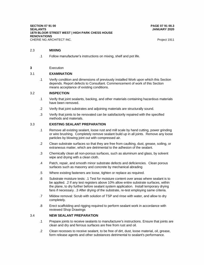
SECTION 07 91 00 SEALANTS 1879 BLOOR STREET WEST | HIGH PARK CHESS HOUSE RENOVATIONS
PAGE 07 91 00.3 JANUARY 2020
CHERIE NG ARCHITECT INC. Project 1911
2.3 MIXING
.1 Follow manufacturer’s instructions on mixing, shelf and pot life.
3 Execution
3.1 EXAMINATION
.1 Verify condition and dimensions of previously installed Work upon which this Section depends. Report defects to Consultant. Commencement of work of this Section means acceptance of existing conditions.
3.2 INSPECTION
.1 Verify that joint sealants, backing, and other materials containing hazardous materials have been removed.
.2 Verify that joint substrates and adjoining materials are structurally sound.
.3 Verify that joints to be renovated can be satisfactorily repaired with the specified methods and materials.
3.3 EXISTING SEALANT PREPARATION
.1 Remove all existing sealant, loose rust and mill scale by hand cutting, power grinding or wire brushing. Completely remove sealant build up in all joints. Remove any loose particles by blowing joint out with compressed air.
.2 Clean substrate surfaces so that they are free from caulking, dust, grease, soiling, or extraneous matter, which are detrimental to the adhesion of the sealant.
.3 Chemically clean all non-porous surfaces, such as aluminum and glass, by solvent wipe and drying with a clean cloth.
.4 Patch, repair, and smooth minor substrate defects and deficiencies. Clean porous surfaces such as masonry and concrete by mechanical abrading
.5 Where existing fasteners are loose, tighten or replace as required.
.6 Substrate moisture tests: .1 Test for moisture content over areas where sealant is to be applied. .2 If any test registers above 10% allow entire substrate surfaces, within the plane, to dry further before sealant system application. Install temporary drying fans if necessary. .3 After drying of the substrate, re-test employing same criteria.
.7 Mildew removal: Scrub with solution of TSP and rinse with water, and allow to dry completely.
.8 Erect scaffolding and rigging required to perform sealant work in accordance with reviewed Shop Drawings
3.4 NEW SEALANT PREPARATION
.1 Prepare joints to receive sealants to manufacturer's instructions. Ensure that joints are clean and dry and ferrous surfaces are free from rust and oil.
.2 Clean recesses to receive sealant, to be free of dirt, dust, loose material, oil, grease, form release agents and other substances detrimental to sealant's performance.
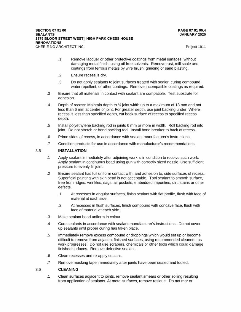
SECTION 07 91 00 SEALANTS 1879 BLOOR STREET WEST | HIGH PARK CHESS HOUSE RENOVATIONS
PAGE 07 91 00.4 JANUARY 2020
CHERIE NG ARCHITECT INC. Project 1911
.1 Remove lacquer or other protective coatings from metal surfaces, without damaging metal finish, using oil-free solvents. Remove rust, mill scale and coatings from ferrous metals by wire brush, grinding or sand blasting.
.2 Ensure recess is dry.
.3 Do not apply sealants to joint surfaces treated with sealer, curing compound, water repellent, or other coatings. Remove incompatible coatings as required.
.3 Ensure that all materials in contact with sealant are compatible. Test substrate for adhesion.
.4 Depth of recess: Maintain depth to ½ joint width up to a maximum of 13 mm and not less than 6 mm at centre of joint. For greater depth, use joint backing under. Where recess is less than specified depth, cut back surface of recess to specified recess depth.
.5 Install polyethylene backing rod in joints 6 mm or more in width. Roll backing rod into joint. Do not stretch or bend backing rod. Install bond breaker to back of recess.
.6 Prime sides of recess, in accordance with sealant manufacturer's instructions.
.7 Condition products for use in accordance with manufacturer’s recommendations.
3.5 INSTALLATION
.1 Apply sealant immediately after adjoining work is in condition to receive such work. Apply sealant in continuous bead using gun with correctly sized nozzle. Use sufficient pressure to evenly fill joint.
.2 Ensure sealant has full uniform contact with, and adhesion to, side surfaces of recess. Superficial painting with skin bead is not acceptable. Tool sealant to smooth surface, free from ridges, wrinkles, sags, air pockets, embedded impurities, dirt, stains or other defects.
.1 At recesses in angular surfaces, finish sealant with flat profile, flush with face of material at each side.
.2 At recesses in flush surfaces, finish compound with concave face, flush with face of material at each side.
.3 Make sealant bead uniform in colour.
.4 Cure sealants in accordance with sealant manufacturer's instructions. Do not cover up sealants until proper curing has taken place.
.5 Immediately remove excess compound or droppings which would set up or become difficult to remove from adjacent finished surfaces, using recommended cleaners, as work progresses. Do not use scrapers, chemicals or other tools which could damage finished surfaces. Remove defective sealant.
.6 Clean recesses and re-apply sealant.
.7 Remove masking tape immediately after joints have been sealed and tooled.
3.6 CLEANING
.1 Clean surfaces adjacent to joints, remove sealant smears or other soiling resulting from application of sealants. At metal surfaces, remove residue. Do not mar or
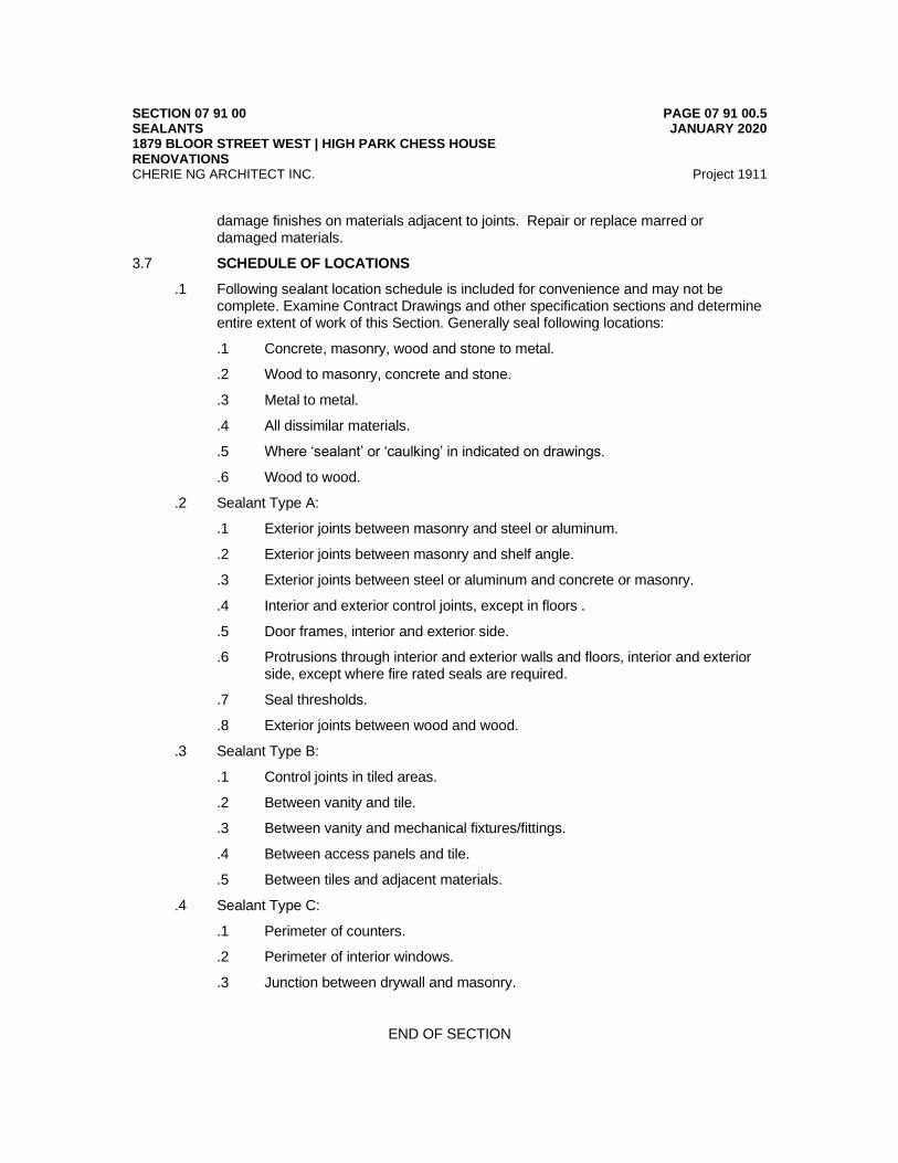
SECTION 07 91 00 SEALANTS 1879 BLOOR STREET WEST | HIGH PARK CHESS HOUSE RENOVATIONS
PAGE 07 91 00.5 JANUARY 2020
CHERIE NG ARCHITECT INC. Project 1911
damage finishes on materials adjacent to joints. Repair or replace marred or damaged materials.
3.7 SCHEDULE OF LOCATIONS
.1 Following sealant location schedule is included for convenience and may not be complete. Examine Contract Drawings and other specification sections and determine entire extent of work of this Section. Generally seal following locations:
.1 Concrete, masonry, wood and stone to metal.
.2 Wood to masonry, concrete and stone.
.3 Metal to metal.
.4 All dissimilar materials.
.5 Where ‘sealant’ or ‘caulking’ in indicated on drawings.
.6 Wood to wood.
.2 Sealant Type A:
.1 Exterior joints between masonry and steel or aluminum.
.2 Exterior joints between masonry and shelf angle.
.3 Exterior joints between steel or aluminum and concrete or masonry.
.4 Interior and exterior control joints, except in floors .
.5 Door frames, interior and exterior side.
.6 Protrusions through interior and exterior walls and floors, interior and exterior side, except where fire rated seals are required.
.7 Seal thresholds.
.8 Exterior joints between wood and wood.
.3 Sealant Type B:
.1 Control joints in tiled areas.
.2 Between vanity and tile.
.3 Between vanity and mechanical fixtures/fittings.
.4 Between access panels and tile.
.5 Between tiles and adjacent materials.
.4 Sealant Type C:
.1 Perimeter of counters.
.2 Perimeter of interior windows.
.3 Junction between drywall and masonry.
END OF SECTION
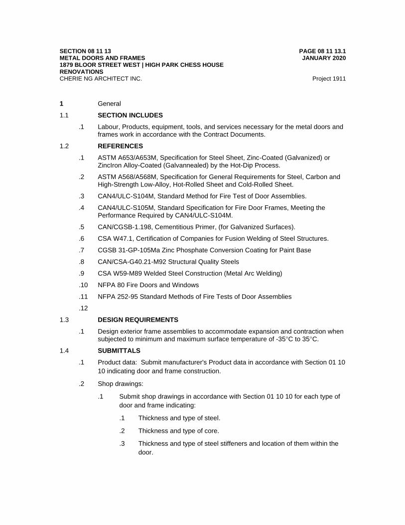
SECTION 08 11 13 METAL DOORS AND FRAMES 1879 BLOOR STREET WEST | HIGH PARK CHESS HOUSE RENOVATIONS
PAGE 08 11 13.1 JANUARY 2020
CHERIE NG ARCHITECT INC. Project 1911
1 General
1.1 SECTION INCLUDES
.1 Labour, Products, equipment, tools, and services necessary for the metal doors and frames work in accordance with the Contract Documents.
1.2 REFERENCES
.1 ASTM A653/A653M, Specification for Steel Sheet, Zinc-Coated (Galvanized) or ZincIron Alloy-Coated (Galvannealed) by the Hot-Dip Process.
.2 ASTM A568/A568M, Specification for General Requirements for Steel, Carbon and High-Strength Low-Alloy, Hot-Rolled Sheet and Cold-Rolled Sheet.
.3 CAN4/ULC-S104M, Standard Method for Fire Test of Door Assemblies.
.4 CAN4/ULC-S105M, Standard Specification for Fire Door Frames, Meeting the Performance Required by CAN4/ULC-S104M.
.5 CAN/CGSB-1.198, Cementitious Primer, (for Galvanized Surfaces).
.6 CSA W47.1, Certification of Companies for Fusion Welding of Steel Structures.
.7 CGSB 31-GP-105Ma Zinc Phosphate Conversion Coating for Paint Base
.8 CAN/CSA-G40.21-M92 Structural Quality Steels
.9 CSA W59-M89 Welded Steel Construction (Metal Arc Welding)
.10 NFPA 80 Fire Doors and Windows
.11 NFPA 252-95 Standard Methods of Fire Tests of Door Assemblies
.12
1.3 DESIGN REQUIREMENTS
.1 Design exterior frame assemblies to accommodate expansion and contraction when subjected to minimum and maximum surface temperature of -35°C to 35°C.
1.4 SUBMITTALS
.1 Product data: Submit manufacturer's Product data in accordance with Section 01 10
10 indicating door and frame construction.
.2 Shop drawings:
.1 Submit shop drawings in accordance with Section 01 10 10 for each type of
door and frame indicating:
.1 Thickness and type of steel.
.2 Thickness and type of core.
.3 Thickness and type of steel stiffeners and location of them within the
door.
SECTION 08 11 13 METAL DOORS AND FRAMES 1879 BLOOR STREET WEST | HIGH PARK CHESS HOUSE RENOVATIONS
PAGE 08 11 13.2 JANUARY 2020
CHERIE NG ARCHITECT INC. Project 1911
.4 Thickness and type of metal facing on edges of door and method of
fastening.
.5 Location of mortises, reinforcement, anchorages, joining, welding,
sleeving, exposed fasteners, openings and arrangement for hardware.
.2 Include schedule identifying each unit with door marks and numbers relating
to numbering on Contract Drawings and in door schedule
.3 Mill Certification: Submit mill certification on all materials used to fabricate
items specified.
1.5 QUALITY ASSURANCE
.1 Perform work in accordance with requirements by a member of the Canadian Steel
Door and Frame Manufacturers Association.
.2 Label and list fire rated doors and frames by an organization acceptable to
authorities having jurisdiction and accredited by the Standards Council of Canada in
conformance with CAN4/ULC-S104M and CAN4/ULC-S105M for ratings indicated,
labelling shall be in accordance with NFPA 80.
2 Products
2.1 ACCEPTABLE MANUFACTURERS
.1 Apex Industries
.2 Daybar Industries Limited
.3 Fleming Doors Products.
.4 Steel-Craft Door Products Ltd
2.2 MATERIALS
.1 General:
.1 All materials under work of this Section, including but not limited to, primers
are to have low VOC content limits.
.2 Materials used for the door & frame construction in this section to conform to:
CAN/CSA-G40.21, Type 44W coating designation to ASTM A653.
.3 Galvanized Steel Sheets: (G90) Mill phosphatize in addition to coating
specified at referenced HM standard. Provide at shower, washrooms doors
and frames and other doors and frames where indicated as well as at
exterior doors and frames.
.4 Supports and Anchors: Same material as frame including gage and
galvanizing where indicated.
SECTION 08 11 13 METAL DOORS AND FRAMES 1879 BLOOR STREET WEST | HIGH PARK CHESS HOUSE RENOVATIONS
PAGE 08 11 13.3 JANUARY 2020
CHERIE NG ARCHITECT INC. Project 1911
.5 Inserts, Bolts, and Fasteners: Manufacturer’s standard units. Hot-dip
galvanize in compliance with ASTM A 153, Class C or D as applicable at
exterior walls and where opening is indicated to be galvanized.
.6 Provide shop primers for security hollow metal doors & frames were welded.
.2 Minimum base steel thickness:
.1 Frames 2.7 mm G90 Galvanized steel
.2 Typical doors 1.91 mm G90 Galvanized steel faces
.3 Lock/strike reinforcements 1.6 mm
.4 Hinge reinforcements 2.7 mm
.5 All other reinforcement 1.6 mm
.6 Top and bottom channels 1.2 mm
.7 Glazing stops 0.9 mm
.8 Guard boxes 0.9 mm
.9 Jamb spreaders 0.9 mm
.3 Top caps and thermal breaks: CGSB 41-GP-19Ma; Rigid PVC extrusions.
.4 Primer: CAN/CGSB 1.198.
.5 Door material:
.1 Interior and Exterior Doors: Provide minimum 1.91 mm (14 gauge) sheet
G90 galvanized steel faces.
.2 Stiffeners: Provide 16ga A40 galvanneal stiffeners to extend full height top to
bottom and maximum 75 mm(3”) from door sides. Where stiffeners are not
continuous between face sheets, weld internal joints 100 mm (4”) o.c. max.
Cope at hardware preparations only. Provide one of the following stiffener
types:
.3 Edge Channels: Continuously weld to both face sheets.
.4 Flush Closing Channels: Continuously weld to both face sheets.
.5 Insulation: Core mineral fiber 48 kg/cubic meters density minimum.
.6 Hardware Reinforcements and Preparations: Comply with referenced HM
standard and the following:
.1 Strike Plate: Do not cut edge channel to receive entire strike or
keeper. Provide punched opening to engage bolt in edge channel
matching cut-out in strike plate.
.2 Drilling and tapping for surface applied hardware may be done at
project site.
SECTION 08 11 13 METAL DOORS AND FRAMES 1879 BLOOR STREET WEST | HIGH PARK CHESS HOUSE RENOVATIONS
PAGE 08 11 13.4 JANUARY 2020
CHERIE NG ARCHITECT INC. Project 1911
.7 Fire rated doors: Mineral fibre insulation to CAN/ULC S702, Type 1A; 24
kg/m3.
.6 Screws: Stainless steel screws with countersunk flat head.
.7 Door silencers: Type 6-180, black neoprene.
.8 Frame anchors:
.1 Frames in steel stud partitions: 0.9 mm minimum steel anchors of suitable
design securely welded inside each jamb.
.2 Floor anchors: 1.6 mm minimum adjustable floor clip angles with 2 holes for
anchorage to floor.
.3 Frames in existing walls: 0.9 mm minimum frame anchors to suit design.
.4 Labeled frames: In accordance with ULC requirements.
.9 Floor anchors: 1.6 mm minimum adjustable floor clip angles with 2 holes for
anchorage to floor.
.10 Labels for fire doors and door frame: Brass plate, riveted to door and door frame.
2.3 Grilles: Corrosion resistant steel with baked enamel finish. Model 61DG Series by Nailor Industries Inc or approved alternative by Hart and Cooley.
2.4 FABRICATION
.1 General
.1 Fabricate doors and frames in accordance with reviewed shop drawings.
.2 Welding: CSA W59-M to produce a finished unit with no visible seams or
joints, square, true and free of distortion.
.3 Welding: Continuous unless specified otherwise. Execute welding by a firm
fully acceptable to the Canadian Welding Bureau to requirements of CSA
W47.1.
.4 Form profiles accurately to details shown on Contract Drawings.
.5 Ream and remove burrs from drilled and punched holes.
.6 Grind welded corners and joints to a flat plane and fill with metallic filler and
sand to a uniform smooth finish. Apply one coat of primer.
.7 Provide weather strip for exterior doors in accordance with Section 08 70 00
and door manufacturer.
.2 Frames and screens:
.1 Fabricate frames of welded construction. Cut mitres and joints accurately and
weld continuously on inside of frame profile. Exterior frames to be thermally
broken.

SECTION 08 11 13 METAL DOORS AND FRAMES 1879 BLOOR STREET WEST | HIGH PARK CHESS HOUSE RENOVATIONS
PAGE 08 11 13.5 JANUARY 2020
CHERIE NG ARCHITECT INC. Project 1911
.2 Construct large frame sections with provision for on Site assembly to suit Site
conditions.
.3 Blank, reinforce, drill and tap frames for mortised, templated hardware.
Protect mortised cut-outs with guard boxes.
.4 Reinforce frames where required for surface mounted hardware.
.5 Reinforce frames over 1200 mm wide with roll formed steel channels or
hollow structural sections specified in Section 05 50 00 and as indicated on
drawings.
.6 Furnish exterior door frames with a continuously welded integral steel
weather drip at head of frame.
.7 Prepare each door opening for single stud rubber door silencers, 3 for single
door openings located in strike jamb, and 2 for double door openings located
in head.
.8 Install 2 channel or angle spreaders per frame, to ensure correct frame
alignment. Install stiffener plates or spreaders between frame trim where
required, to prevent bending of trim and to maintain alignment when setting
in place.
.9 Frame Fill: Prepare heads, jambs, and sills abutting structure, walls, or floors
for solid anchorage with full grout fill. Exclude grout from mullions except
where otherwise indicated.
.1 Grout Guards: At frames to be grouted, tightly weld 0.45 mm(0.018”)
minimum steel grout guards at screw holes, cut outs, and hardware
preparations including those for removable glazing stops, locksets,
pushbuttons, strike plates, hinges, etc. Additionally at hinge
preparations Contractor to provide polyurethane or polystyrene foam
fill or otherwise tightly seal grout guards to keep screw holes grout
free.
.3 Anchorage:
.1 Anchor units to floor and wall construction. Locate each wall anchor
immediately above or below each hinge reinforcement on hinge jamb and
directly opposite on strike jamb, minimum number of anchors for each jamb:
.1 Frames up to 2285 mm 3 anchors.
.2 Frames from 2285 mm to 2440 mm 4 anchors.
.2 Where frames are to be set in masonry or concrete, supply adjustable
anchors to trade installing frame.
.3 Fabricate frames for installation in steel stud partitions with steel anchors of
suitable design, minimum number of anchors for each jamb:

SECTION 08 11 13 METAL DOORS AND FRAMES 1879 BLOOR STREET WEST | HIGH PARK CHESS HOUSE RENOVATIONS
PAGE 08 11 13.6 JANUARY 2020
CHERIE NG ARCHITECT INC. Project 1911
.1 Frames up to 2285 mm height 4 anchors.
.2 Frames 2285 mm to 2440 mm 5 anchors.
.4 Frames in previously placed concrete, masonry, precast or structural steel:
.1 Anchors located at 150 mm maximum from top and bottom of each
jamb, and intermediate anchors at maximum 660 mm o.c.
.4 General Door Requirements:
.1 Hollow steel construction, flush swing type, of sizes to conform to details,
schedules and reviewed shop drawings with provisions for cut-outs for glass
and grilles and reinforced to receive hardware fastenings.
.2 Blank, reinforce, drill and tap doors for mortised, templated hardware. Where
required, reinforce doors for surface mounted hardware and door closers.
.3 Reinforce oversized doors with steel channels and plates specified in Section
05 50 00 and as indicated on drawings.
.4 Where openings are required, form integral cut-outs with framing, glass stop
moldings and division bars.
.5 Install grilles to fit tight and secure into openings.
.6 Bevel both stiles of single doors 1 in 16.
.7 Reinforce doors with galvanized metal stiffeners at 150 mm o.c.
.5 Interior Doors:
.1 Supply and install inverted, recessed, mechanically interlocked with tack
welded channels at top and bottom of doors.
.2 Fabricate doors with joints between front and back panels meeting on stile
edges. Make joints mechanically interlocked and tack welded for entire
height of door. After welding has been completed, grind joints smooth to
match metal. Ensure that no filler is used in joints.
.3 Fill hollow space within door and vertical stiffeners from top to bottom with
mineral fibre batt insulation.
.6 Fire Rated Doors:
.1 Supply and install inverted, recessed, spot welded channels at top and
bottom of doors. Supply and install steel flush top caps on exterior doors.
.2 Fabricate doors with joints between front and back panels meeting on stile
edges. Make joints continuously welded for entire height of door. After
welding has been completed, grind joints smooth to match metal. Ensure that
no filler is used in joints.

SECTION 08 11 13 METAL DOORS AND FRAMES 1879 BLOOR STREET WEST | HIGH PARK CHESS HOUSE RENOVATIONS
PAGE 08 11 13.7 JANUARY 2020
CHERIE NG ARCHITECT INC. Project 1911
.3 Fabricate doors to achieve fire rating as indicated on drawings and in
accordance with ULC. Provide ULC label plate on door at hinged edge
midway between top hinge and head of door.
3 Execution
3.1 EXAMINATION
.1 Verify condition and dimensions of previously installed Work upon which this Section depends. Report defects to Consultant. Commencement of work of this Section means acceptance of existing conditions.
3.2 HOLLOW METAL DOOR AND FRAME INSTALLATION
.1 Install hollow metal doors and frames plumb, square, level, secure, and at correct elevation.
.2 Install doors clear of floor finishes, and with the correct rebate opening for the door installation. Install door silencers.
.3 Secure anchorages and connections to adjacent construction. Brace frames rigidly in position while building-in. Remove temporary steel shipping jamb spreaders. Install wood spreaders at third points of frame rebate height to maintain frame width. Supply and install vertical supports as indicated on drawings for openings over 1200 mm in width. Remove wood spreaders after frames have been built-in.
.4 Allow for structural deflection and prevent structural loads from being transmitted to hollow metal frames.
.5 Touch-up areas where galvanized coating has been removed or damaged with primer.
.6 Fire rated doors: Install fire rated doors and frames in accordance with requirements of NFPA 80.
3.3 ADJUSTING AND CLEANING
.1 Adjust doors for smooth and balanced door movement.
.2 Clean doors and frames.
END OF SECTION

SECTION 08 70 00 FINISH HARDWARE 1879 BLOOR STREET WEST | HIGH PARK CHESS HOUSE RENOVATIONS
PAGE 08 70 00.1 JANUARY 2020
CHERIE NG ARCHITECT INC. Project 1911
1 General
1.1 SECTION INCLUDES
.1 Labour, Products, equipment and services necessary for finish hardware work in accordance with the Contract Documents.
1.2 REFERENCES
.1 BHMA, Builders Hardware Manufacturing Association.
.2 NFPA 80, Standard for Fire Doors and Other Opening Protectives.
1.3 SUBMITTALS
.1 Product data: Submit manufacturer's Product data in accordance with Section 01 10 10 indicating compliance with reference standards, transportation, storage, handling and installation requirements.
.2 Shop Drawings:
.1 Submit Shop Drawings and 3 complete hardware lists in accordance with Section 01 10 10 indicating:
.1 Door locations, sizes, hardware manufacturer's catalogue numbers, finish symbols and quantities required.
.2 Locations and mounting heights of each type of hardware.
.2 Supply templates and required information to door and frame manufacturer to enable accurate sizes, locations of cut-outs and reinforcement for hardware.
.3 Submit templates to required trade to arrange for provisions for accurate setting and fitting of hardware.
.3 Samples:
.1 Submit 2 samples in accordance with Section 01 10 10 of each item that is different from hardware specified and include manufacturer's parts lists and installation instructions.
.2 Submit hardware component samples illustrating style, colour and finish. Tag samples identifying applicable Specification article number, brand name and number, finish, building location, date and catalogue number.
.3 Do not order hardware until samples have been accepted. Submit new samples to replace rejected samples. Supply hardware and finishes identical to each accepted sample.
.4 Closeout submittals:
.1 Submit the following in accordance with Section 01 10 10 for each Product for incorporation into Operation and Maintenance Manual:
.1 Maintenance data.
.2 Operating instructions and safety precautions.
.3 Parts list with name and address of supplier.
.4 Lubrication schedule and type of lubricant recommended.
SECTION 08 70 00 FINISH HARDWARE 1879 BLOOR STREET WEST | HIGH PARK CHESS HOUSE RENOVATIONS
PAGE 08 70 00.2 JANUARY 2020
CHERIE NG ARCHITECT INC. Project 1911
.5 Keys, tools and special devices.
.6 Inspection procedures related to preventive maintenance
1.4 QUALITY ASSURANCE
.1 General:
.1 Manufacturers: Companies specializing in manufacturing door hardware.
.2 Hardware supplier: Company specializing in supplying commercial door hardware and acceptable to manufacturer.
.2 Certifications:
.1 Employ an Architectural Hardware Consultant to inspect completed installation and certify that hardware has been installed in accordance with manufacturer's printed instructions, Authorities having Jurisdiction and as specified.
.2 Submit manufacturer's certificate that finish hardware and fire rated hardware meets specified requirements.
1.5 DELIVERY, STORAGE, AND HANDLING
.1 Be responsible for packaging of hardware, on a set by set basis. As material is received from various manufacturers identify it to correspond to Hardware List symbols.
.2 Label packages legibly, indicating manufacturer's number, types, sizes, opening number and Hardware List reference number. Wrap hardware and include in package, screws, bolts and fastening necessary for correct installation. If hardware package is not complete, pay additional charges incurred by installer.
.3 Deliver hardware to Site packaged, labelled and cross-referenced to hardware list for each item and its scheduled installation location.
.4 Accept Products of this Section on Site and ensure that each item is undamaged.
.5 Catalogue and store hardware in secure area.
2 Products
2.1 GENERAL
.1 Provide hardware schedule to Consultant for approval indicating products, materials and finishes. Do not order products until schedule has been approved by Consultant.
.2 Carefully check and verify Hardware List against Contract Drawings to ensure that hardware listed can be used as specified. Inform Consultant of concerns regarding quality, quantity, operation or function of hardware selected:
.1 Verify hand of doors, examine details on Contract Drawings and at Site to ensure hardware supplied can be correctly installed and is correct for work as constructed.
.2 Select hardware in accordance with applicable codes and regulations and to approval of local Fire Marshal.
SECTION 08 70 00 FINISH HARDWARE 1879 BLOOR STREET WEST | HIGH PARK CHESS HOUSE RENOVATIONS
PAGE 08 70 00.3 JANUARY 2020
CHERIE NG ARCHITECT INC. Project 1911
.3 Replace and pay for defective hardware including hardware which was incorrectly selected, and remedial and installation costs.
.3 Ensure that hardware selected will function correctly, meets Contract requirements and Ontario Building Code and authorities having jurisdiction.
.4 Ensure that each hardware item is of same type, design and by same manufacturer.
.5 Manufacturer's names or trade marks are not permitted on exposed surfaces of hardware.
.6 Include in packing slip a list of parts, name of supplier and door number in which lock is to be installed.
.7 Hardware for fire rated and labelled door and frame assemblies: ULC listed or as accepted by authorities having jurisdiction.
.8 Fire rated assemblies:
.1 Hardware: Selected and installed in accordance with applicable codes and regulations, NFPA-80 and to approval of [Ontario] Fire Marshal.
.2 Fire rated doors: ULC labelled hardware. Submit written certification of conformance to ULC requirements for each type of hardware prior to delivery.
.3 Locksets and latchsets on fire rated doors: 19 mm throw minimum.
2.2 ACCESSORIES
.1 Items to be attached to masonry or concrete with expandable shields, lag screws, bolts or other fastening devices as required. Exposed screws: Stainless steel, Phillips or Robertson heads.
2.3 FINISHES
.1 Metal finishes: Free from defects, clean, unstained and of a uniform colour for each type of finish required. Exposed surfaces and anchors: Specified finish symbol of item.
3 Execution
3.1 EXAMINATION
.1 Verify condition and dimensions of previously installed Work upon which this Section depends. Report defects to Consultant. Commencement of work of this Section means acceptance of existing conditions.
3.2 INSTALLATION
.1 Install hardware in accordance with reviewed Shop Drawings, manufacturer's installation instructions, and applicable Codes and regulations.
.2 Install hardware in accordance with hardware templates.
.3 Adjust fixed and operable hardware for correct clearances and function.
.4 Mount hardware measured from finished floor to centre of hardware, unless indicated otherwise or required by Code:
.1 Top hinge: 250 mm from head of door to top.
.2 Bottom hinge: 265 mm from finished floor to bottom of hinge.

SECTION 08 70 00 FINISH HARDWARE 1879 BLOOR STREET WEST | HIGH PARK CHESS HOUSE RENOVATIONS
PAGE 08 70 00.4 JANUARY 2020
CHERIE NG ARCHITECT INC. Project 1911
.3 Intermediate hinge: Equal distance between top and bottom hinge.
.4 Locksets, latchsets: 1000 mm.
.5 Panic device crossbar: 1000 mm.
.6 Push plates: 1100 mm to bottom of plates.
.7 Guard bars: 1100 mm.
.8 Door pulls: 1100 mm to bottom of pulls.
.9 Blank strike: 1450 mm.
.10 Blank fronts: 1450 mm.
.5 Include for supply and installation of wiring for electric strikes from electrical junction box to electric strike hardware.
.6 Locate door stops to contact doors 75 mm from latch edge.
.7 Install hardware and trim square and plumb to doors.
.8 Replace wrappings for hardware provided by manufacturer after installation.
.9 Safeguard keys to keep them out of unauthorized hands, tag them with door number, and deliver them to person designated by Consultant at building completion.
3.3 FIELD QUALITY CONTROL
.1 Have hardware inspected after installation by hardware supplier's representative, obtain certification in writing that hardware has been supplied and installed in accordance with Specifications and hardware manufacturer's instructions and is functioning correctly.
.2 Inspect fire rated openings to ensure they are installed in compliance with NFPA 80 requirements and Authorities having Jurisdiction.
.3 Test access control system and electrified hardware devices for proper operation. Verify electric door release hardware operates properly upon activation of fire alarm system.
3.4 ADJUSTING
.1 Verify under work of this Section, that installed hardware functions properly.
.2 Adjust hardware so that latches and locks operate smoothly and without binding, and closers act positively with the least possible resistance in use. Lubricate hardware if required by manufacturer's instructions.
.3 Adjust doors with self closing devices or automatic closing devices for proper operation after the HVAC system is balanced and adjusted. Verify spring power of non sized door closers is properly adjusted.
3.5 CLEANING
.1 Remove wrappings at completion of the Project and clean hardware in accordance with manufacturer's instructions
END OF SECTION
SECTION 08 71 13 AUTOMATIC DOOR EQUIPMENT 1879 BLOOR STREET WEST | HIGH PARK CHESS HOUSE RENOVATIONS
PAGE 08 71 13.1 JANUARY 2020
CHERIE NG ARCHITECT INC. Project 1911
1 General
1.1 SECTION INCLUDES
.1 Design, labour, Products, tool, equipment and services necessary for automatic door
equipment work in accordance with the Contract Documents.
1.2 REFERENCES
.1 ANSI/BHMA A156.19, Power Assist and Low-Energy Power-Operated Doors.
1.3 DESIGN REQUIREMENTS
.1 Design handicap door system comprising of low energy power operator with optional
push and go door system as defined in ANSI/BHMA A156.19.
.2 Design system operator to activate if one push button from either side of door is
pushed. Actuated door shall open slowly to back check (80o) in 3 to 6 seconds and
to full open position in 4 to 7 seconds. Door shall remain open for period set to suit
requirements (period of 5 to 30 seconds). After time delay door shall close by spring
in door operator from 90o to 10o in 3 to 6 seconds from 10o to fully closed in 1-1/2
to 2 seconds.
1.4 SUBMITTALS
.1 Product data: Submit duplicate copies of manufacturer's Product data in accordance
with Section 00 13 00 indicating performance criteria, compliance with appropriate
reference standard(s), characteristics, limitations, trouble-shooting protocol,
transportation, storage, handling and installation requirements.
.2 Shop drawings: Submit shop drawings in accordance with Section 01 10 10
indicating all connections, attachments, reinforcing, anchorage and location of
exposed fastenings.
1.5 EXTENDED WARRANTY
.1 Submit an extended warranty for automatic door equipment in accordance with
General Conditions, except that warranty period is extended to 5 years.
.1 Warrant against failure to meet design criteria and requirements.
.2 Coverage: Complete replacement including affected adjacent Work.
2 Products
2.1 ACCEPTABLE MANUFACTURER(S) AND SYSTEM(S)
.1 Heavy Duty Door Operator:
.1 Design is based on self contained, low pressure electro-hydraulic power.
Operator to be as manufactured by one of the following:
.1 “RHINO ADO 4000” by Rhinotek.
.2 Approved Equivalent by Horton Automatics or Falcon.
SECTION 08 71 13 AUTOMATIC DOOR EQUIPMENT 1879 BLOOR STREET WEST | HIGH PARK CHESS HOUSE RENOVATIONS
PAGE 08 71 13.2 JANUARY 2020
CHERIE NG ARCHITECT INC. Project 1911
.2 For use at corridor doors, entry vestibule doors and any additional areas as
indicated
2.2 EQUIPMENT
.1 MANUFACTURED DOOR UNITS: Surface Applied Operator with Connecting Arms:
The operator header shall be mounted to the surface of the existing door frame or
wall. Connecting hardware shall be a double arm arrangement that can either push
the door or pull the door open to suit the job condition. When the operator mounting
is on the pull side and adjacent wall is within 4" (101.6 mm) of the door frame,
specify a parallel arm.
.2 OPERATOR: The Electric Operating Mechanism shall be Style 4000 or Approved
Equivalent. The operator shall be shock mounted and concealed in an extruded
aluminum 6 1/2" x 6 1/2" side access header extending the full width of door or a
minimum 32" in length. Opening force shall be accomplished by a 1/8 HP D.C.
permanent magnet motor working through reduction gears to the output shaft.
Closing force shall be supplied by a field replaceable spring. When the door is in the
closing mode or fully closed, motor voltage shall not be required and will be off. The
door can be manually operated with power on or off without damage to the operator.
The master control unit shall incorporate an adjustable time delay of 1 to 99 seconds
(ANSI A156.19 requirement is 5 second minimum time delay). It shall provide infinite
adjustment to opening and back check speeds including adjusting the opening force
without affecting the opening speed. The master control unit shall provide for
immediate reversal of door motion without undue strain on the drive train by
supplying stepped voltage to the motor. The door shall reverse when closing if an
object stops the door. A locked door motor protection circuit will be supplied that will
limit current to the motor if it is applied when the door is inadvertently locked or
otherwise prevented from opening.
.3 OPERATION: Automatic and/or Manual:
.1 Automatic: Pushbutton switch actuates door open; door closes after time
delay expires. Operator to include the following variable adjustments so as to
comply with ANSI Standard A156.19: Opening speed - 4 to 6 seconds;
Closing speed - 4 to 6 seconds. Opening and closing force, measured 1"
(25.4 mm) out from the lock stie of the door, not to exceed 15 pounds (67 N)
of force to stop the door when operating in either direction.
.2 Manual: Push-To-Open: Manually pushing door activates automatic opening
cycle; door closes after time delay expires. Time delay for manual push-to-
open operation can be independently adjustable from 1-99 seconds.
.4 RELATED EQUIPMENT
.1 ACTIVATING DEVICE: Shall be marked Press to Open and located on each
side of the opening as per ANSI Safety Standard A117.
.2 Push plate: 4-1/2” Diameter (114.3 mm) round or square, stainless steel
SECTION 08 71 13 AUTOMATIC DOOR EQUIPMENT 1879 BLOOR STREET WEST | HIGH PARK CHESS HOUSE RENOVATIONS
PAGE 08 71 13.3 JANUARY 2020
CHERIE NG ARCHITECT INC. Project 1911
switch.
.5 RELATED WORK REQUIREMENTS
.1 ELECTRICAL: 120 VAC, 60 cycle, 1 phase, 15 amp. Two low-voltage wires
shall be furnished to connect push button/plate switch to the operator.
.6 MATERIALS, FINISHES AND FABRICATION
.1 EXTRUDED ALUMINUM: ASTM B221, 6063-T5 alloy and temper, anodized:
1. Structural Header Sections: Minimum 1/8" (3 mm) thickness; capable of
self-support of transom glass above.
.2 FINISHES (for all exposed aluminum surfaces):
.1 204-R1 Clear: Arch. Class ll Clear Anodized Coating, AA-MI2C22A31.
.3 OPERATOR CONSTRUCTION: Electromechanical.
.1 Door operating equipment shall be complete with electro mechanical motor
gear box. Provide 3 position (off-on) switch. System shall operate between
-30 deg C and 50 deg C.
.2 Provide all components and accessories as required for complete
installation of automatic door equipment including but not limited to push
button switches, relays and door controls. Types to be as recommended by
automatic door equipment manufacturer to suit respective system.
.7 REQUIREMENTS
.1 Functional Requirements:
.1 Equipment shall be designed to operate swing doors up to weight of
100 kg.
.2 Opening Speed:
.1 Door shall be field adjusted to back check as required in Table 1
of ANSI/BHMA A156.19.
.2 Opening speed to fully open shall be 4 seconds or longer.
.2 Hold Open: Door shall be field adjusted to remain fully open for not less
then 5 seconds or more than 30 seconds.
.3 Closing Speed:
.1 Doors shall be field adjusted to close 90 degree to 10 degree in 3
seconds or longer as required in Table 1 of ANSI/BHMA A156.19.
.2 Doors shall close from 10o to fully closed in not less than 1.5
seconds.
.3 Force required to prevent door from opening or closing shall not
exceed 7 kg applied 25 mm from latch edge of door at any point in
opening or closing cycle.
SECTION 08 71 13 AUTOMATIC DOOR EQUIPMENT 1879 BLOOR STREET WEST | HIGH PARK CHESS HOUSE RENOVATIONS
PAGE 08 71 13.4 JANUARY 2020
CHERIE NG ARCHITECT INC. Project 1911
.4 During power failure, doors shall open with manual pressure not
exceeding 11.3 kg at point 25 mm from latch edge of door.
.5 Doors shall be equipped with signs visible from either side, instructing
user as to operation and function of door.
.4 Requirements:
.1 Provide header complete with full housing, finish shall match door frame
finish.
.2 Locations of automatic door operators to conform to requirements of the
Ontario Building Code (OBC).
.3 Operator shall be activated by 150 mm diameter stainless steel push
button switches with a satin finish on either sides as indicated, complete
with text and/logos as approved by the Consultant.
.4 Switches shall bear universal handicap logo visible to all types of traffic.
.5 Stainless steel post: In accordance with Contract Documents.
Coordinate with noted Section as required for installation of automatic
door equipment at post.
3 Execution
3.1 EXAMINATION
.1 Verify condition and dimensions of previously installed Work upon which this Section
depends. Report defects to Consultant. Commencement of Work means acceptance
of existing conditions.
3.2 INSTALLATION
.1 Install automatic door operators, controls and accessories for doors indicated in
accordance with reviewed shop drawings and manufacturer written instructions
.2 Installation of automatic door operators to be in accordance with requirements of the
Ontario Building Code (OBC).
.3 Install door units plumb, level and true to line with manufacturer's prescribed
tolerances. Provide support and anchor in place.
.4 Comply with AAMA 101, Appendix Dissimilar Materials ls separating aluminum
materials and other corrodible surfaces from sources of corrosion or electrolytic
action contact points.
.5 General or electrical contractor to install all wiring to operator on a separate circuit
breaker routed into header.
.6 Doors shall operate manually as though equipped with manual door closers, without
damage to automatic door components, in event of power failure or in event of
power termination.

SECTION 08 71 13 AUTOMATIC DOOR EQUIPMENT 1879 BLOOR STREET WEST | HIGH PARK CHESS HOUSE RENOVATIONS
PAGE 08 71 13.5 JANUARY 2020
CHERIE NG ARCHITECT INC. Project 1911
.7 Coordinate this work with applicable door Sections requiring automatic door
equipment and for post for door equipment.
.8 Power supply to each door operator and wiring shall be provided by Division 26 -
Electrical. Make connections at operators and at control panel and supply and install
each electrical work between operators and activating controls. Comply with
requirements of Division 26 - Electrical. All wiring shall be concealed and where
exposed shall be run in conduit. Location of exposed wiring shall be subject to
Consultant's approval.
3.3 ADJUSTMENT AND CLEANING
.1 Test and adjust operators and controls smooth and proper operation.
.2 Upon completion of Work of this Section, remove from Site all debris, equipment and
excess material resulting from Work of this Section.
.3 Installer to adjust operator and controls for optimum condition and safe ty.
END OF SECTION

SECTION 09 21 16 GYPSUM BOARD 1879 BLOOR STREET WEST | HIGH PARK CHESS HOUSE RENOVATIONS
PAGE 09 21 16.1 JANUARY 2020
CHERIE NG ARCHITECT INC. Project 1911
1 General
1.1 SECTION INCLUDES
.1 Design, labour, Products, equipment and services necessary for gypsum board work.
1.2 REFERENCES
.1 ASTM A653/A653M, Specification for Steel Sheet, Zinc-coated (Galvanized) or ZincIron Alloy-Coated (Galvannealed) by the Hot-Dip Process.
.2 ASTM C475, Specification for Joint Compound and Joint Tape for Finishing Gypsum Board.
.3 ASTM C645, Specification for Nonstructural Steel Framing Members.
.4 ASTM C665, Mineral-Fiber Blanket Thermal Insulation for Light Frame Construction and Manufactured Housing.
.5 ASTM C754, Specification for Steel Framing Members to Receive Screw-Attached Gypsum Board.
.6 ASTM C834, Standard Specification for Latex Sealants.
.7 ASTM C840, Specification for Application and Finishing of Gypsum Board.
.8 ASTM C1002, Specification for Steel Self-Piercing Tapping Screws for the Application of Gypsum Panel Products or Metal Plaster Bases to Wood Studs or Steel Studs.
.9 ASTM C1178, Specification for Glass Mat Water-Resistant Gypsum Backing Board.
.10 ASTM C1278, Specification for Fiber-Reinforced Gypsum Panel.
.11 ASTM C1396, Specification for Gypsum Board.
.12 ASTM E84, Standard Test Method for Surface Burning Characteristics of Building Materials.
1.3 DESIGN REQUIREMENTS
.1 Design ceiling suspension system in accordance with manufacturer's printed directions and ASTM C754.
.2 Design ceiling system for adequate support of electrical fixtures as required by the current bulletin of the Electrical Safety Authority.
.3 Design hanger anchor and entire suspension system static loading not to exceed 25% of their ultimate capacity including lighting fixture dead loads.
.4 Design suspension system to support weight of mechanical and electrical items such as air handling boots and lighting fixtures, and with adequate support to allow rotation/relocation of light fixtures.
.5 Design subframing as necessary to accommodate, and to circumvent, conflicts and interferences where ducts or other equipment prevent the regular spacing of hangers.
.6 Design wall framing system and reinforce as necessary to accommodate and support items attached to and supported by wall framing system.
.7 Design wall framing system for wall assemblies with a height greater than 3000 mm and those assemblies incorporating non-standard gypsum board assemblies
SECTION 09 21 16 GYPSUM BOARD 1879 BLOOR STREET WEST | HIGH PARK CHESS HOUSE RENOVATIONS
PAGE 09 21 16.2 JANUARY 2020
CHERIE NG ARCHITECT INC. Project 1911
including, but not limited to, abuse resistant gypsum board, large format tile applications, etc.
1.4 REGULATORY REQUIREMENTS
.1 Provide fire separations and fire protection exactly as specified in test design specification that validates the specified rating. Verify that work specified in other Sections, as a part of the entire assembly, meets applicable validating test design specification.
1.5 SUBMITTALS
.1 Product data:
.1 Submit copies of manufacturer's Product data in accordance with Section 01 10 10 indicating:
.1 Performance criteria, compliance with appropriate reference standard, characteristics, and limitations.
.2 Product transportation, storage, handling and installation requirements.
.2 Shop Drawings:
.1 Submit Shop Drawings in accordance with Section 01 10 10 indicating:
.1 Wall assemblies, suspension systems, adjacent construction, elevations, sections and details, dimensions, thickness, finishes and relationship to adjacent construction.
.2 Framing and blocking for items being supported of wall systems.
.3 Certifications: Submit written certification stating that suspended ceiling system is designed for adequate support of electrical fixtures as required by the current bulletin of the Electrical Safety Authority.
1.6 QUALITY ASSURANCE
.1 Qualifications: Execute the work of this Section by skilled, qualified, and experienced workers trained in the installation of the work of this Section.
.2 Retain a Professional Engineer, licensed in Province of Ontario, with experience in work of comparable complexity and scope, to perform following services as part of work of this Section:
.1 Design of wall systems with height greater than 3000 mm and at nonstandard gypsum board assemblies including, but not limited to, assemblies incorporating abuse resistant gypsum board, large format tile applications, etc.
.2 Design of suspended gypsum board assemblies.
.3 Review, stamp, and sign Shop Drawings and design calculations.
.4 Conduct shop and on-site inspections, prepare and submit written inspection reports verifying that this part of Work is in accordance with Contract Documents and reviewed Shop Drawings.
1.7 SITE CONDITIONS
.1 Do not begin work of this Section until:
SECTION 09 21 16 GYPSUM BOARD 1879 BLOOR STREET WEST | HIGH PARK CHESS HOUSE RENOVATIONS
PAGE 09 21 16.3 JANUARY 2020
CHERIE NG ARCHITECT INC. Project 1911
.1 Mechanical and electrical work above the ceiling is complete.
.2 Substrate and ambient temperature is above 15 degrees Celsius.
.3 Relative humidity is below 80%.
.4 Ventilation is adequate to remove excess moisture.
.2 Install temporary protection and facilities to maintain Product manufacturer's, and above specification, environmental requirements 24 h before, during, and 24 h after installation.
2 Products
2.1 MATERIALS
.1 General:
.1 All materials under work of this Section, including but not limited to, sealants, adhesives, and primers are to have low VOC content limits.
.2 Steel framing: ASTM C754; ASTM A653/A653-M, Z275; cold rolled, galvanized steel sheet.
.1 Bailey Metal Products Limited
.2 Corus Metal Profiles
.3 Steel studs and track runners: ASTM C645; Galvanized steel studs and runners, 32 mm wide x depth as indicated on Contract Drawings. Formed from galvanized steel sheet, thicknesses as follows:
.1 Studs less than 3000 mm: Minimum 0.53 mm (25 ga.).
.2 Studs greater than 3000 mm and non-standard assemblies: Minimum 0.91 mm (20 ga.), unless stud thickness of greater thickness is required to accommodate intended loading, spans, or conditions.
.3 Track runners and ancillary components to match stud thickness.
.4 Main carrying channels: ASTM C645; Formed from galvanized steel sheet, 38 x 19 mm cold rolled, channels.
.5 Resilient channel: ASTM C645; 0.5 mm thick galvanized metal, 57 mm wide x 12 mm deep for walls and ceiling to reduce sound transmission.
.6 Furring channels: ASTM C645; Formed from galvanized steel sheet, 22 mm winged flange type, cold rolled.
.7 Furring channels (hat type): ASTM C645; 0.5 mm base steel thickness, galvanized. 70 mm wide x 22 mm deep hat shaped channel.
.8 Heavy duty furring channels: ASTM C645; 0.9 mm steel thickness, galvanized hat shaped channel with a wider and deeper size as required by manufacturers.
.9 Hanger wires: 4.1 mm minimum diameter galvanized pencil rod.
.10 Tie wire: 1.6 mm thick minimum diameter, soft annealed, galvanized steel wire.
SECTION 09 21 16 GYPSUM BOARD 1879 BLOOR STREET WEST | HIGH PARK CHESS HOUSE RENOVATIONS
PAGE 09 21 16.4 JANUARY 2020
CHERIE NG ARCHITECT INC. Project 1911
.11 Corner bead, casing bead, and special shapes: Formed from 0.6 mm thick minimum, galvanized steel sheet, designed to be concealed by joint compound.
.12 Deflection track: ASTM C 645 top runner with 50.8-mm- deep flanges, in thickness indicated for studs and in width to accommodate depth of studs.
.13 Deflection track (fire rated): Provide 25 mm deep leg deflection track where indicated on rated walls. ‘Fire Trak Shadowline’ by Fire Trak Corporation or approved alternative.
.14 Ceiling clips: Hot dip galvanized partition attachment clips, in square and reveal edge; ‘PAC 15 Series’ to match grid system by CGC Inc. or approved alternative.
.15 Gaskets (acoustic partitions): Adhesive-backed, closed-cell vinyl foam strips that allow fastener penetration without foam displacement, 3.2 mm thick, in width to suit steel stud size.
.16 Control joint strip: Roll formed from galvanized steel sheet, with a tape protected recess, 6 mm wide x 11 mm deep.
.17 Screw fasteners: ASTM C1002 Type S; Corrosion resistant.
.18 Concrete anchors: tie wire sleeve anchors, ‘Redi-Drive Anchors' by ITW Red Head or approved alternative.
.19 Acoustic/Fire insulation: ASTM C665, Paperless, semi-rigid, spun mineral fibre mats, of thickness as indicated on Contract Drawings, ‘Sustainable Insulation, NoiseReducer’ by CertainTeed, ‘EcoTouch Quiet Zone Pink Fiberglas Acoustic Insulation’ by Owens Corning Inc. or ‘Roxul AFB’ by Roxul Inc.
.20 Sealants:
.1 Acoustic sealant (non-rated): Non-hardening acoustic sealant for use at nonrated assemblies, ASTM C834; Acrylic, mould resistant sealant, paintable. ‘Smoke and Acoustic Sealant CP506' by Hilti or approved alternative.
.2 Sealant (fire-rated): Non-hardening sealant for use at fire-rated assemblies: ASTM E84; Acrylic based firestop sealant, colour: red or white as selected by Consultant. ‘Flexible Firestop Sealant CP606' by Hilti or approved alternative.
.3 Standard sealants: In accordance with Section 07 91 00.
.21 Aqua-Tough Moisture and Abuse Resistant Board: ASTM D3273, ASTM C1278 and ASTM C1629 (GB-1); gypsum board 15.9 mm thick of maximum practical lengths to minimize end joints, unless indicated otherwise. Furnish Board by CGC Inc.
.22 Primer: Where indicated by board manufacturer, provide primer as required to achieve finishes as defined in ASTM C840.
.23 Joint reinforcing tape:
.1 Standard gypsum board: ASTM C475; 50 mm wide x 0.25 mm thick, perforated paper, with chamfered edges.
.2 Moisture resistant and tile backer boards: ASTM C475; fibreglass mat joint tape as recommended by board manufacturer to suit location.
SECTION 09 21 16 GYPSUM BOARD 1879 BLOOR STREET WEST | HIGH PARK CHESS HOUSE RENOVATIONS
PAGE 09 21 16.5 JANUARY 2020
CHERIE NG ARCHITECT INC. Project 1911
.24 Bonding adhesive: Type for purpose intended and as recommended and approved by manufacturer.
.25 Joint and patching compound: ASTM C475; Asbestos-free, supplied by manufacturer of gypsum board used.
.26 Fast setting patching compound: ASTM C475; Asbestos-free, Sheetrock or Durabond by CGC Inc., ‘Moisture and Mold Resistant Setting Compound with M2Tech’ by Certainteed Gypsum Canada or approved alternative.
.27 Access doors: Supplied by other Sections for installation as part of the work of this Section
3 Execution
3.1 EXAMINATION
.1 Verify condition and dimensions of previously installed Work upon which this Section depends. Report defects to Consultant. Commencement of work of this Section means acceptance of existing conditions.
3.2 SUSPENSION FRAMING
.1 Install ceiling systems in accordance with reviewed Shop Drawings and manufacturer's written instructions.
.2 Install hanger wires plumb and securely anchored to the building structural framing, independent of walls, pipes, ducts, and metal deck; install additional framing and hangers to bridge interference items.
.3 Install hanger wires at 1200 mm maximum centres along carrying channels, not less than 25 mm, and not more than 150 mm from channel ends.
.4 Install additional hangers at lighting fixture and ductwork locations. Do not attach hanger wires to mechanical or electrical equipment. Do not support mechanical and electrical fixtures and fitting on ceiling without the ceiling manufacturer's written acceptance.
.5 Install main carrying channels transverse to structural framing members. Lap main carrying channels 200 mm minimum at splices and wire each end with two loops and prevent clustering or lining-up of splices.
.6 Install furring channels at 400 mm o.c., not less than 25 mm, and not more than 150 mm from perimeter walls, at openings, at interruptions in ceiling continuity, and at change in plane. Install furring channels to a tolerance of 3 mm maximum in 3600 mm.
.7 Install additional main carrying and furring channels to frame and to reinforce openings such as recessed lighting fixtures, access hatches, ceiling grilles, outlet boxes, ventilating outlets and similar items.
3.3 STEEL STUDS AND FURRING
.1 Install steel studs and furring in accordance with reviewed Shop Drawings and manufacturer's written instructions.
SECTION 09 21 16 GYPSUM BOARD 1879 BLOOR STREET WEST | HIGH PARK CHESS HOUSE RENOVATIONS
PAGE 09 21 16.6 JANUARY 2020
CHERIE NG ARCHITECT INC. Project 1911
.2 Install steel stud partitions to underside of structure unless indicated otherwise.
.3 Install track runners at floors, ceilings, and underside of structure; align track runners accurately and secure to structure at 600 mm centres maximum.
.4 Install double top track runner assembly to prevent the transmission of structural loads to steel studs.
.5 Install steel studs vertically at 400 mm o.c., unless otherwise indicated, and not more than 50 mm from abutting walls, at openings, and at each side of corners. Install studs securely to track runners.
.6 Schedule and coordinate steel framing installation with mechanical and electrical services installation.
.7 Install full height, double studs at door and service openings, fastened together and stiffened back to the structure to prevent vibration when doors close.
.8 Provide double studs boxed together at all openings, sill, head and jambs and at door jambs, fastened together and stiffened back to the structure to prevent vibration. At each opening exceeding 900 mm in width, double studs shall be 20 ga. extending to structure above, and adequately anchored at each end. Provide steel studs above and below openings spaced at 400 mm oc maximum. All metal stud partitions above doors and screens over 1220 mm wide shall be secured to structure over and reinforced with sway bracing to stabilize walls to prevent lateral movement.
.9 Erect three studs at corner and intermediate intersections of partitions. Space 50 mm apart and brace together with wired 19 mm channels.
.10 Stiffen partitions over 2440 mm high or 3000 mm long, or both, with horizontal bracing extended for full length of partitions. Provide one line of bracing in partitions. Space lines to provide equal unbraced panels. Provide bracing for portions of partitions over door openings in partitions over 3000 mm high, and bracing both above and below openings in partitions located no greater than 150 mm from top and bottom of opening, and extending two stud spaces beyond each edge of opening for both doors and windows. Wire tie or weld bracing to studs.
.11 Frame control joints using back to back double studs at abutting structural elements, at dissimilar backup interface, at dissimilar walls and ceilings, at structural expansion and control joints, at door and other openings, and at 9000 mm maximum spacing in continuous runs. Install control joint strips and secure in place.
.12 Install additional support framing at openings and cutouts for built-in equipment, upper cabinet support, access panels and similar items.
.13 Attach to framing adequate steel reinforcing members or a 1.2 mm (18 ga.) steel stud mounted horizontally and notched around furring members to support the load of, and to withstand the withdrawal and shear forces imposed by, items installed upon the work of this Section. Such items include, but are not restricted to, miscellaneous metals, coat hooks, washroom accessories, handrail anchors, rub rails, grab bars, guards, wall-hung cabinets and fitments, shelving, curtain and drape tracks, miscellaneous specialties; Owner supplied equipment; and minor mechanical and electrical work. Heavy mechanical and electrical equipment shall be selfsupporting in Divisions 21, 22, 23 and 26.
SECTION 09 21 16 GYPSUM BOARD 1879 BLOOR STREET WEST | HIGH PARK CHESS HOUSE RENOVATIONS
PAGE 09 21 16.7 JANUARY 2020
CHERIE NG ARCHITECT INC. Project 1911
.14 Provide for support and incorporation of flush-mounted and recessed mechanical and electrical equipment and fixtures only after consultation and verification of methods with those performing the work of Divisions 21, 22, 23 and 26.
.15 Install cross bracing in accordance with the steel stud manufacturer's recommendations.
3.4 FIRE RATED ASSEMBLIES
.1 Install Products in fire rated assemblies in strict accordance with applicable ULC tested and approved designs.
.2 Stiffen fire rated walls over 3.66 m high, where linear length of wall is greater than 2.44 m between perpendicular wall supports, with diagonal bracing above the ceiling extending perpendicular to wall at a 45E angle to structure above. Locate diagonal bracing at maximum 2.44 m o.c.
.3 Where double layers of gypsum board are shown, and required for fire rating, screw first layer to studs and furring and laminate the second layer to the first using joint filler as an adhesive. Stagger joints between first and second layers.
3.5 ACOUSTICAL INSULATION
.1 Install acoustic insulation in partitions, between steel studs, and as indicated on Contract Drawings and in accordance with the manufacturer's instructions. Fill stud cavities to full height of partitions and carefully cut and fit acoustic insulation around services and protrusions.
3.6 ACOUSTICAL SEALANT
.1 Install acoustical sealant to acoustically insulated partitions in accordance with the manufacturer's instructions and Contract Drawings.
.2 Install acoustical sealant under floor runner track, at partition perimeter both sides and at openings, cut-outs, and penetrations, concealed from view in the final installation.
.3 Install firestop fill material behind fire rated acoustical sealant and provide firestop identification tag.
.4 Smooth acoustical sealant with trowel prior to skin forming.
3.7 BUILT-IN CORNER GUARDS
.1 Install built-in corner guards in accordance with manufacturer’s written instructions level, secure and rigid.
3.8 GYPSUM BOARD
.1 Comply with ASTM C840. Install gypsum board in accordance with reviewed Shop Drawings and manufacturer's written instructions.
.2 Install gypsum board vertically or horizontally, whichever results in fewer end joints. Locate end joints over supporting members.
.3 Install gypsum board in lightly butted contact at edges and ends and with 1.6 mm maximum open space between boards; do not force gypsum board into place. Do not install imperfect, damaged or damp boards.
SECTION 09 21 16 GYPSUM BOARD 1879 BLOOR STREET WEST | HIGH PARK CHESS HOUSE RENOVATIONS
PAGE 09 21 16.8 JANUARY 2020
CHERIE NG ARCHITECT INC. Project 1911
.4 Install gypsum board butting paired tapered edge joints, and mill-cut or field-cut end joints; do not place tapered edges against cut edges or ends.
.5 Install vertical joints minimum 300 mm from the jamb lines of openings and stagger vertical joints over different studs on opposite sides of partitions.
.6 Do not locate joints within 200 mm of corners or openings, except where control joints occur at jamb lines or where openings occur adjacent to corners. Where necessary, place a single vertical joint over the centre of wide openings.
.7 Cut, drill and patch gypsum board as may be necessary to accommodate the work of other trades.
.8 Fire Separations:
.1 Construct gypsum board assemblies, where located, in accordance with tested assemblies to obtain required or indicated fire rated assemblies. As a minimum fire separations shall consist of metal framing covered on both sides by fire-rated gypsum board.
.2 Install assemblies tightly to enclosing constructions to maintain integrity of the separations. Install casing beads at all perimeter edges.
3.9 CORNER, CASING BEADS AND TRIM
.1 Corner reinforcing bead: Install along all external angles, erect plumb, level and with a minimum of joints. Secure with screws at 225 mm o.c. apply filler over flanges flush with nose of the bead and extending at least 75 mm onto surface of board each side of corner. When filler dries, apply a thin coat of topping cement and blend onto adjoining surfaces.
.2 Casing bead: Install where wallboard butts against a surface having no trim concealing the juncture and where shown on drawings. Erect casing beads plumb or level, with minimum joints, and secure with screws at 300 mm o.c. apply filler over flange flush with bead and extending at least 75 mm onto surface of board. When dry, apply a thin coat of topping cement and blend onto adjoining surfaces.
.3 Recess channels and trim: Install recess channels and special metal trim where shown. Secure to substrate. Provide casing beads full height on wallboard edges at recess channels and metal trim.
3.10 JOINT TAPING AND FINISHING
.1 Install reinforcing tape and a minimum of 3 coats of joint compound over gypsum board joints, metal trim and accessories, and screw fasteners in accordance with the gypsum board manufacturer's instructions.
.2 Fill gaps between, and any imperfections in, gypsum boards with joint compound, allow to dry, and sand smooth ready for painting.
.3 Install finished gypsum board work smooth, seamless, plumb, true, flush, and with square, plumb, and neat corners.
.4 Finish gypsum board in accordance with ASTM C840 to the following grades:
.1 Level 0: No taping, finishing, or accessories required. Use above suspended ceilings and within other concealed spaces, unless the assembly is fire rated,
SECTION 09 21 16 GYPSUM BOARD 1879 BLOOR STREET WEST | HIGH PARK CHESS HOUSE RENOVATIONS
PAGE 09 21 16.9 JANUARY 2020
CHERIE NG ARCHITECT INC. Project 1911
sound rated, sound or smoke controlled, or unless the space serves as an air plenum.
.2 Level 1: At joints and interior angles embed tape in joint compound. Leave surface free of excess joint compound. Tool marks and ridges are acceptable. Use above suspended ceilings and within other concealed spaces if the gypsum board assembly is fire rated, sound rated, sound or smoke controlled, or the space serves as an air plenum.
.3 Level 2: At joints and interior angles embed tape in joint compound with one separate coat of joint compound applied over joints, angles, fastener heads, and accessories. Use for water resistant gypsum board indicated for use as a substrate for ceramic tile.
.4 Level 3: At joints and interior angles embed tape in joint compound with two separate coats of joint compound applied over all joints, angles, fastener heads, and accessories. Apply joint compound smooth and free of tool marks and ridges. Use where heavy grade wall coverings are the final decoration.
.5 Level 4: At joints and interior angles embed tape in joint compound with three separate coats of joint compound applied over all joints, angles, fastener heads, and accessories. Apply joint compound smooth and free of tool marks and ridges. Use for all locations except those indicated for other finish levels.
.6 Level 5: At joints and interior angles embed tape in joint compound with three separate coats of joint compound applied over all joints, angles, fastener heads, and accessories. Apply a thin skim coat of joint compound, or a material manufactured especially for this purpose, to the entire surface. Leave surface smooth and free of tool marks and ridges. Use where semi-gloss or gloss finish coatings are the final decoration.
3.11 ACCESS DOORS
.1 Install access doors, supplied as part of other parts of the work, in accordance with manufacturer’s written instructions.
3.12 SITE TOLERANCES
.1 Install metal support systems to ensure that, within a tolerance of +3 mm and -1.5 mm for plaster thickness, finish surfaces will be flat within 3 mm under a 3 m straightedge, and with no variation greater than 1.5 mm in any running 300 mm, and that surface planes shall be within 3 mm of dimensioned location.
3.13 WORK IN EXISTING AREAS
.1 In existing areas, where existing gypsum board work has been demolished and/or damaged and repair work is required, provide new gypsum board finish.
.2 Thoroughly prepare areas to be repaired. Provide neat, clean and straight cuts.
.3 Finish all repair work as specified for new work.
.4 In existing areas where existing openings are to be filled in with gypsum board, provide new gypsum board wall and ceiling construction. Ensure new board faces are flush with faces of abutting existing walls and ceilings.
3.14 REPAIR

SECTION 09 21 16 GYPSUM BOARD 1879 BLOOR STREET WEST | HIGH PARK CHESS HOUSE RENOVATIONS
PAGE 09 21 16.10 JANUARY 2020
CHERIE NG ARCHITECT INC. Project 1911
.1 Make good cut-outs for services and other work, fill in defective joints, holes and other depressions with joint compound.
.2 Make good defective work, and ensure that surfaces are smooth, evenly textured and within specified tolerances to receive finish treatments.
END OF SECTION

SECTION 09 30 00 TILE 1879 BLOOR STREET WEST | HIGH PARK CHESS HOUSE RENOVATIONS
PAGE 09 30 00.1 JANUARY 2020
CHERIE NG ARCHITECT INC. Project 1911
1 General
1.1 SECTION INCLUDES
.1 Labour, Products, equipment and services necessary for tile work in accordance with the Contract Documents.
1.2 REFERENCES
.1 ANSI A108/A118/A136.1, Installation of Ceramic Tile.
.2 ANSI A137.1, Specifications for Ceramic Tile.
.3 ASTM C144, Specification for Aggregate for Masonry Mortar.
.4 ASTM C920, Specification for Elastomeric Joint Sealants.
.5 CAN/CSA A3000, Cementitious Materials Compendium.
.6 CGSB 71-GP-22M, Organic Adhesive for Installation of Ceramic Wall Tile.
.7 ISO 23599, Assistive Products for Blind and Vision-Impaired Persons - Tactile Walking Surface Indicators.
.8 TTMAC Specification Guide 09300 Tile Installation Manual.
.9 TTMAC, Maintenance Guide.
1.3 SUBMITTALS
.1 Product data:
.1 Submit copies of manufacturer's Product data in accordance with Section 01 10 10 indicating:
.1 Performance criteria, compliance with appropriate reference standard, characteristics, limitations and warranties.
.2 Product transportation, storage, handling and installation requirements.
.2 Shop drawings:
.1 Submit shop drawings in accordance with Section 01 10 10 indicating:
.1 Tile layout, patterns, and colour arrangement.
.2 Perimeter conditions, junctions with dissimilar materials.
.3 Setting details
.3 Samples:
.1 Submit following sample panels in accordance with Section 01 10 10.
.1 Each colour, texture, size, and pattern of tile.
.2 Adhere tile samples to 400 x 400 x 12.5 mm thick cement board complete with selected grout colour in joints.
.4 Certificates: Submit manufacturer's certificates stating that materials supplied are in accordance with this specification.

SECTION 09 30 00 TILE 1879 BLOOR STREET WEST | HIGH PARK CHESS HOUSE RENOVATIONS
PAGE 09 30 00.2 JANUARY 2020
CHERIE NG ARCHITECT INC. Project 1911
.5 Closeout submittals: Submit recommended maintenance instructions and listing of recommended maintenance Products for incorporation into Operations and Maintenance Manuals in accordance with Section 01 10 10.
1.4 QUALITY ASSURANCE
.1 Perform work of this Section by a company with proven, acceptable experience on installations of similar complexity and scope.
1.5 DELIVERY, STORAGE AND HANDLING
.1 Deliver materials in adequate crates or containers with manufacturer’s name and product description clearly marked.
.2 Handle and store tiles in a manner to avoid chipping, breakage or the instruction of foreign matter. Take precautions to protect the mortar and grout admixtures from freezing or from excessive heat.
1.6 SITE CONDITIONS
.1 Do not install work of this Section outside of the following environmental ranges without the Consultant's and Product manufacturer's written acceptance:
.1 Ambient air and surface temperature: 150C to 450C.
.2 Precipitation: None.
.2 Install temporary protection and facilities to maintain the Product manufacturer's, and specified, environmental requirements for 7 Days before, during, and 7 Days after installation.
1.7 MAINTENANCE
.1 Submit extra tile amounting to 3% of gross area covered, allowing proportionately for each pattern and type specified and which are part of the same Production run as installed Products. Store maintenance Products as directed by the Consultant.
2 Products
2.1 MATERIALS
.1 General: All materials under work of this Section, including but not limited to, sealants, adhesives, and sealers are to have low VOC content limits.
.2 Tile:
.1 To ANSI A137.1.
.2 Supply coves, caps, inside and outside corners and bullnose tile as required.
.3 Where unfinished tile edge is exposed, supply cap to Consultant’s selection.
.4 Tile Types:
.1 Porcelain tile (POR-1): Porcelain floor tile, sized at 2” x 2” mosaic tile. 'Keystones' by Daltile or approved alternative. To be selected by the Consultant from the manufacturer’s full colour range in Price Group 1.

SECTION 09 30 00 TILE 1879 BLOOR STREET WEST | HIGH PARK CHESS HOUSE RENOVATIONS
PAGE 09 30 00.3 JANUARY 2020
CHERIE NG ARCHITECT INC. Project 1911
.2 Ceramic tile (CT-1): ‘Modern Dimensions’ ceramic tile size 4 ¼” x 12 ¾”, by Daltile or approved alternative from Stone Tile International or Olympia Tile To be selected by the Consultant from the manufacturer’s full colour range in Semi-Gloss, Price Group 3.
.3 Porcelain Tile Base: Cove porcelain base tile to match floor porcelain tile.
.5 Floor Divider Strip (THR-1): Stainless steel edge, continuous at sloped transitions between porcelain tile to sheet flooring, depth as required to suit flooring thickness. ‘Schiene’ by Schluter Systems or approved alternative.
.6 Floor Divider Strip (THR-2): Stainless steel edge, continuous at sloped transitions between porcelain tile to existing sheet flooring or concrete flooring, depth as required to suit flooring thickness. ‘RENO-U’ by Schluter Systems or approved alternative.
.7 Wall edge protection: Aluminium edge protection with trapezoid-perforated anchoring leg and an anodized finish, continuous at all exposed tile edges, depth as required to suit tile thickness. ‘Jolly’ by Schluter Systems or approved alternative.
.8 POR-1 Baseboard edge protection: Aluminium edge protection with trapezoid-perforated anchoring leg and an anodized finish, continuous at all exposed tile edges, depth as required to suit tile thickness. ‘Jolly’ by Schluter Systems or approved alternative.
2.2 ACCESSORIES
.1 Cement: CAN/CSA A3000, Type GU.
.2 Sand: ASTM C144.
.3 Water: Potable and free of minerals and other contaminants which are detrimental to mortar and grout mixes.
.4 Polymer additive: Keralastic by Mapei Inc or approved alternative by Ardex, Flextile Ltd. or Laticrete International.
.5 Thin-set mortar: 2 component to ANSI A108/A118/A136.1:
.1 ‘Kerabond with Keralastic Latex Additive’ by Mapei Inc., ‘Ardex X77 Microtec' by Ardex, ‘56SR/51 w/44' by Flextile Ltd., or ‘254/255' by Laticrete International.
.2 White coloured mortar shall be provided at appropriate tile types including, but not limited to; glass tile, light coloured marble, green marble and light coloured granite.
.6 Medium bed mortar: to ANSI A118.4:
.1 ‘Ultraflex LFT’ by Mapei Inc., or approved alternative by Ardex, Flextile Ltd., or Laticrete International.
.2 White coloured mortar shall be provided at appropriate tile types including, but not limited to; glass tile, light coloured marble, green marble and light coloured granite
SECTION 09 30 00 TILE 1879 BLOOR STREET WEST | HIGH PARK CHESS HOUSE RENOVATIONS
PAGE 09 30 00.4 JANUARY 2020
CHERIE NG ARCHITECT INC. Project 1911
.7 Thick bed sloped topping: Factory mixed blend of portland cement and aggregates with latex admix. ‘Ardex X32 Microtec’ by Ardex, ‘226 thick bed mortar with 3701 admix’ by Laticrete, or ‘Topcem with Planicrete AC Admixture’ by Mapei Inc.
.8 Primer: To meet specified requirements of adhesive manufacturer.
.9 Cleaner: In accordance with TTMAC’s requirements and as recommended by tile manufacturer.
.10 Organic adhesive (walls): CGSB 71-GP-22M, Type 1.
.11 Grout:
.1 Floors and bases (below 3 mm joint width): ‘Keracolor U’ by Mapei Inc. or approved alternative by Ardex, Flextile Ltd. or Laticrete International.
.2 Floors and bases (3 mm to 10 mm joint width): ‘UltraColor Plus’ by Mapei Inc. or approved alternative by Ardex, Flextile Ltd. or Laticrete International.
.3 Walls (1.5 mm to 3 mm joint width): ‘Keracolor U' by Mapei Inc. or approved alternative by Ardex, Flextile Ltd. or Laticrete International.
.4 Walls (over 3 mm joint width): ‘Ultracolour Plus’ by Mapei Inc. or approved alternative by Ardex, Flextile Ltd. or Laticrete International.
.5 Grout colour: To be selected by the Consultant from the manufacturer’s full colour range.
.12 Tile sealant: In accordance with Section 07 91 00.
2.3 MIXES
.1 Levelling bed mix:
.1 1 part Portland cement.
.2 4 parts sand.
.3 1 part water (including polymer additive), adjusted for water content of sand
.4 1/10 part polymer additive.
3 Execution
3.1 EXAMINATION
.1 Verify condition and dimensions of previously installed Work upon which this Section depends. Report defects to Consultant. Commencement of work of this Section means acceptance of existing conditions.
3.2 SURFACE PREPARATION
.1 Clean and dry surfaces thoroughly. Remove oil, wax, grease, dust, dirt, paint, tar, primers, form release agents, curing compound, and other foreign material from substrate surfaces which may prevent or reduce adhesion.
.2 Neutralize any trace of strong acids or alkali from the substrate.
3.3 CONTROL JOINTS
SECTION 09 30 00 TILE 1879 BLOOR STREET WEST | HIGH PARK CHESS HOUSE RENOVATIONS
PAGE 09 30 00.5 JANUARY 2020
CHERIE NG ARCHITECT INC. Project 1911
.1 Provide control, expansion and isolation joints in accordance with TTMAC specification 301MJ and as indicated on drawings. Install in locations indicated on drawings and specified herein.
.2 Continue control, construction, and cold joints in the structural substrate up through the tile finish, and align with mortar joints where possible. Review joint locations on Site with the Consultant.
.3 Install joint widths to match grout joint widths, except where a minimum width is indicated.
.4 Install control joints in the following typical locations:
.1 Aligned over changes in type of substrate.
.2 At the restraining perimeters such as walls and columns.
.3 Interior areas (not subject to sunlight): 6 mm minimum width, at 7320 mm o.c. maximum.
.4 Interior areas (subject to sunlight): 6 mm minimum width, at 3660 mm o.c maximum.
.5 As indicated on the Contract Drawings.
.5 Seal control joints in accordance with Section 07 91 00.
3.4 LEVELLING BED
.1 Install a levelling bed on uneven substrate surfaces, level and plumb substrates in accordance with the following tolerances:
.1 Vertical surfaces: 3 mm in 2.4 m maximum.
.2 Horizontal surfaces: 6 mm in 3 m from finished levels of the surface, or better.
.2 Clean structural substrate control joints and blow-clean with compressed air. Grout fill control joints flush to slab with levelling bed.
3.5 GENERAL INSTALLATION REQUIREMENTS
.1 Install tiles in accordance with manufacturer's instructions and TTMAC Specification Guide 09300 Tile Installation Manual. Manufacturer's installation instructions govern over TTMAC Installation Manual.
.2 Lay out work to produce a symmetrical pattern with minimum amount of cutting. Ensure cut tile at room perimeter and at joints is not less than ½ full size.
.3 Install trim to be placed under tile in locations indicated on Drawings.
.4 Set tiles in place and rap or beat with a beating block as necessary to ensure a proper bond and to level surface. Align tile for uniform joints and allow to set until firm. Clean excess mortar from surface of tile with a wet cloth or sponge while mortar is fresh.
.5 Ensure following minimum mortar contact coverage to back of tiles. Contact must be evenly distributed to give full support of the tile.
.1 98% for large format (305 mm x 305 mm or greater) interior applications.
.2 90% for non-large format interior applications.
SECTION 09 30 00 TILE 1879 BLOOR STREET WEST | HIGH PARK CHESS HOUSE RENOVATIONS
PAGE 09 30 00.6 JANUARY 2020
CHERIE NG ARCHITECT INC. Project 1911
.6 Adjust joints between units uniform, plumb, straight, even, and true, with adjacent tile flush. Align grout joints in both directions unless indicated otherwise.
.7 Align floor, base and wall grout joints.
.8 Install tile accessory fittings for a complete and fully coordinated tile assembly.
.9 Install wall tile full height unless indicated otherwise.
.10 Do not place tile, trim, and accessories over control, expansion, or isolation joints. Stop materials in either side on joints and provide control, expansion and isolation joints as specified.
.11 Cut and fit tile neatly around piping, fittings, joints, projections and around recesses items e.g. washroom accessories. Where surface mounted equipment and accessories are installed on tile surfaces, extend tile over surfaces. Cut edges smooth, even, and free from chipping; chipped and broken edges are not acceptable.
.12 .12 Do not proceed with grouting until minimum 48 hours after tile has set, to prevent displacement of tiles.
.13 .13 Apply grout in accordance with grout manufacturer's directions to produce watertight, filled joints without voids, cracks and excess grout. Thoroughly compact and tool floor grout. Finish grout flush to edge thickness of tile and remove excess grout with soft burlap or sponge moistened with clean water.
3.6 CLEANING
.1 Clean off excess grout with soft burlap or sponge moistened with clean water.
.2 Polish floor and wall tile after grout has cured in accordance with TTMAC recommendations in the Maintenance Guide; do not use acid for cleaning.
.3 Re-point joints after cleaning as required to eliminate imperfections, then re-clean as necessary. Avoid scratching tile surfaces.
3.7 JOINT BACKING AND TILE SEALANT
.1 Install joint backing under sealant as necessary.
.2 Install tile sealant around piping and fittings extending through tiled surfaces.
.3 Seal tile control joints.
.4 Seal internal tile to tile junctions. Tool to a smooth, flush surface, free from air bubbles and contamination.
3.8 PROTECTION
.1 Prevent traffic over tiled areas, and protect tiled assemblies from weather, freezing, and water immersion, for 72 hours minimum, after final installation.
.2 Prevent direct impact, vibration and heavy hammering on adjacent and opposite walls for 24 hours minimum, after final installation.
.3 Cover work temporarily with building paper properly lapped and taped at joints until work has been approved by Consultant.
END OF SECTION
SECTION 09 91 00 PAINTING 1879 BLOOR STREET WEST | HIGH PARK CHESS HOUSE RENOVATIONS
PAGE 09 91 00.1 JANUARY 2020
CHERIE NG ARCHITECT INC. Project 1911
1 General
1.1 SECTION INCLUDES
.1 Labour, Products, equipment and services necessary for painting work in accordance with the Contract Documents.
1.2 REFERENCES
.1 Master Painters Institute (MPI), Painting Specification Manual.
.2 SSPC Steel Structures Painting Council, Standards.
1.3 SUBMITTALS
.1 Product data:
.1 copies of manufacturer's Product data in accordance with Section 01 10 10 indicating:
.1 Performance criteria, compliance with appropriate reference standard, characteristics, limitations.
.2 Product transportation, storage, handling and installation requirements.
.2 Submit listing of manufacturer's Product types, Product codes, and Product names, number of coats, and dry film thicknesses, corresponding to each Painting Schedule code; submit listing minimum of 8 weeks before materials are required.
.2 Samples:
.1 Submit following samples in accordance with Section 01 10 10.
.1 Three 300 x 150 mm draw downs of each colour minimum 4 weeks before paints are required.
.2 Identify each sample with Contract number and title, colour reference, sheen, date, and name of applicator.
.3 Certificates:
.1 Submit certification from paint manufacturer, on company letterhead, indicating each product proposed for use is Manufacture's premium grade, first line Product.
.2 Submit certified documentation to confirm each airless spray painter has minimum of 5 years experience on applications of similar complexity and scope.
.3 Submit certified documentation to confirm each worker has Provincial Tradesman Qualification certificate of proficiency.
.4 Reports:
.1 Submit written field inspection and test report results after each inspection.
SECTION 09 91 00 PAINTING 1879 BLOOR STREET WEST | HIGH PARK CHESS HOUSE RENOVATIONS
PAGE 09 91 00.2 JANUARY 2020
CHERIE NG ARCHITECT INC. Project 1911
.2 Submit Field Quality Control test result reports for alkali content, substrate moisture, and dry film thickness.
.3 Submit electronic moisture meter manufacturer's specifications including tolerances. Submit record of latest meter calibration to meet manufacturer's recommendations.
1.4 QUALITY ASSURANCE
.1 Finishing work: Perform work to MPI requirements for premium grade.
.2 Supervision: Have work supervised by a full-time qualified foreperson who has 10 years minimum experience on Contracts of similar complexity and scope
.3 Mock-up:
.1 Construct three 3 m2 mock-ups of different Paint Schedule code systems, selected by Consultant, in locations acceptable to Consultant to demonstrate installation workmanship, colour, and hiding power of Products.
.2 Obtain Consultant's acceptance in writing before proceeding with the work of this Section.
.3 Mock-ups may remain as part of the Work if acceptable to Consultant and will serve as a standard for similar code systems.
.4 Repaint over mock-ups which do not form part of the Work.
1.5 DELIVERY, STORAGE, AND HANDLING
.1 Install correct, safe temporary storage for paint, thinner, solvents, and other volatile, corrosive, hazardous, and explosive materials in accordance with requirements of authorities having jurisdiction.
.2 Post hazard warning signage in areas of storage and mixing. Install and maintain sufficient CO2 fire extinguishers of minimum 9 kg capacity, accessible in each storage mixing and storage areas.
.3 Maintain storage enclosures at minimum 10oC ambient temperature and to manufacturer's instructions.
1.6 SITE CONDITIONS
.1 Apply coatings under the following conditions:
.1 Exterior coatings (except Latex): 5o C minimum.
.2 Exterior latex coatings: 10oC minimum.
.3 24 hours minimum after rain, frost, condensation, or dew.
.4 When no condensation is possible (unless specifically formulated against condensation).
.5 Interior coatings: 7oC minimum.
.6 Relative humidity: 85% maximum.
.7 Not in direct exposure to sun light.
SECTION 09 91 00 PAINTING 1879 BLOOR STREET WEST | HIGH PARK CHESS HOUSE RENOVATIONS
PAGE 09 91 00.3 JANUARY 2020
CHERIE NG ARCHITECT INC. Project 1911
.2 Maintain temperature conditions indicated above for 24 hours before, during and 24 hours after painting.
.3 Install clean plywood sheets to protect floors and walls in storage and mixing areas, from paint drips, spatters, and spills.
.4 Apply sufficient masking, clean drop cloths, and protective coverings for full protection of work not being painted including, but not limited to, the following:
.1 Light fixtures, fire and smoke detectors.
.2 Sprinkler heads.
.3 Prepainted diffusers and registers.
.4 Prepainted equipment.
.5 Fire rating labels and equipment specification plates.
.6 Finished surfaces.
1.7 ENVIRONMENTAL PERFORMANCE REQUIREMENTS
.1 Provide paint products meeting MPI "Green Performance Standard GPS-1-05".
1.8 MAINTENANCE
.1 Deliver to Owner's place of storage on completion of work, sealed containers of each finish painting material applied, and in each colour. Label each container as for original, including mixing formula. Provide the following:
.1 1 L of extra materials when less than 50 L are used for Project;
.2 3.78 L of extra stock when 50 to 200 L are used;
.3 7.57 L of extra stock when over 200 L are used.
2 Products
2.1 MATERIALS
.1 Paint:
.1 All materials under work of this Section, including but not limited to, primers, stains, and paints are to have low VOC content limits.
.2 Products in accordance with the MPI Painting Specification Manual, Exterior and
.2 Interior Systems;
.1 For each MPI paint code, manufacture's premium grade, first line Products is to be use.
.2 Uniform dispersion of pigment in a homogeneous mixture.
.3 Ready-mixed and tinted whenever possible.
.3 Products within each MPI paint system code: From single manufacturer.
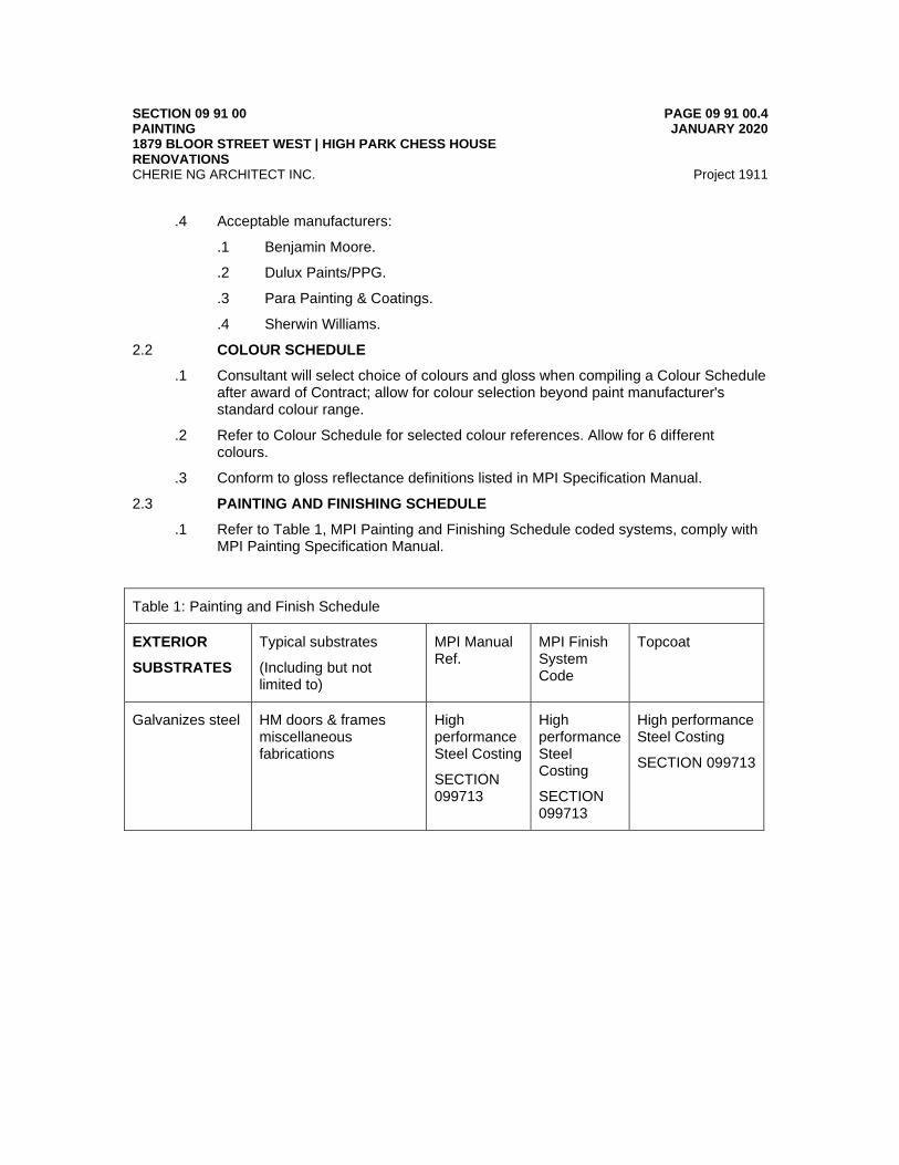
SECTION 09 91 00 PAINTING 1879 BLOOR STREET WEST | HIGH PARK CHESS HOUSE RENOVATIONS
PAGE 09 91 00.4 JANUARY 2020
CHERIE NG ARCHITECT INC. Project 1911
.4 Acceptable manufacturers:
.1 Benjamin Moore.
.2 Dulux Paints/PPG.
.3 Para Painting & Coatings.
.4 Sherwin Williams.
2.2 COLOUR SCHEDULE
.1 Consultant will select choice of colours and gloss when compiling a Colour Schedule after award of Contract; allow for colour selection beyond paint manufacturer's standard colour range.
.2 Refer to Colour Schedule for selected colour references. Allow for 6 different colours.
.3 Conform to gloss reflectance definitions listed in MPI Specification Manual.
2.3 PAINTING AND FINISHING SCHEDULE
.1 Refer to Table 1, MPI Painting and Finishing Schedule coded systems, comply with MPI Painting Specification Manual.
Table 1: Painting and Finish Schedule
EXTERIOR
SUBSTRATES
Typical substrates
(Including but not limited to)
MPI Manual Ref.
MPI Finish System Code
Topcoat
Galvanizes steel HM doors & frames miscellaneous fabrications
High performance Steel Costing
SECTION 099713
High performance Steel Costing
SECTION 099713
High performance Steel Costing
SECTION 099713

SECTION 09 91 00 PAINTING 1879 BLOOR STREET WEST | HIGH PARK CHESS HOUSE RENOVATIONS
PAGE 09 91 00.5 JANUARY 2020
CHERIE NG ARCHITECT INC. Project 1911
3 Execution
3.1 EXAMINATION
.1 Verify condition of previously installed Work upon which this Section depends. Report defects to Consultant. Commencement of work of this Section means acceptance of existing conditions.
3.2 PREPARATION
.1 General:
.1 Clean substrate surfaces free from, dust, grease, soiling, or extraneous matter, which are detrimental to finish.
Table 1: Painting and Finish Schedule Continue
INTERIOR SUBSTRATES
Typical substrates
(Including but not limited to)
MPI Manual Ref.
MPI Finish System Code
Topcoat
Metal Fabrications (Factory Primed)
Vanity supports INT 5.1 INT 5.1R High performance latex
Metal Fabrications
HMF and Door High performance Steel Costing
SECTION 099713
High performance Steel Costing
SECTION 099713
High performance Steel Costing
SECTION 099713
Wood Paneling & casework
Partitions, panels, millwork, window sill and mullions
INT 6.4 INT 6.4E Poly-urethane
Gypsum Board Drywall, walls, ceiling and all previously painted surfaces
INT 9.2 INT 9.2F Epoxy-modified latex
Metal Fabrications
Bench Supports and Legs
High performance Steel Costing
SECTION 099713
High performance Steel Costing
SECTION 099713
High performance Steel Costing
SECTION 099713
SECTION 09 91 00 PAINTING 1879 BLOOR STREET WEST | HIGH PARK CHESS HOUSE RENOVATIONS
PAGE 09 91 00.6 JANUARY 2020
CHERIE NG ARCHITECT INC. Project 1911
.2 Patch, repair, and smoothen minor substrate defects and deficiencies e.g. machine, tool and sand paper marks, shallow gouges, marks, and nibs.
.3 Clean, sweep, and vacuum floors and surfaces to be painted, debris and dustfree prior to painting.
.4 Refer to MPI Painting Specification Manual for surface preparation requirements of substrates not listed here.
.2 Where finish hardware has been installed remove, store, re-install finish hardware, to accommodate painting. Do not clean hardware with solvent that will remove permanent lacquer finishes.
.3 Alkali Content tests and neutralization:
.1 Test for ph level using litmus paper on dampened substrate.
.2 Neutralize surfaces over 8.5 ph with 4% solution of Zinc Sulphate for solvent based systems and tetrapotassium pyrophosphate for latex based systems, to below 8.0 ph, and allow to dry.
.3 Brush-off any residual Zinc Sulphate crystals.
.4 Coordinate paint system primer / sealer to be alkali-resistant.
.4 Substrate moisture tests:
.1 Test for moisture content over entire surface to be painted, minimum one test/2 m2 in field areas and one test/600 mm along inside corners including at ceiling to wall juncture.
.2 If any test registers above 10% allow entire substrate surfaces, within the plane, to dry further before paint system application. Install temporary drying fans if necessary.
.3 Re-test employing same criteria.
.5 Mildew removal: Scrub with solution of trisodium phosphate and sodium hypochlorite (Javex) bleach, rinse with water, and allow to dry completely.
.6 Cementitious and masonry (existing): Clean existing surfaces by pressure washing where indicated on drawings with a TSP solution and pressure range of 1500 - 4000 PSI at 150 mm - 300 mm. Rinse areas with clean water and allow to throughly dry. Provide for collection and disposal of water.
.7 Cementitious and masonry (Concrete, block):
.1 Allow 28 days cure before painting.
.2 Coordinate repair of protrusion-chipping and grinding, and honeycomb filling with responsible trades.
.3 Remove dirt, loose mortar, scale, powder, efflorescence, and other foreign matter.
.4 Remove form oil and grease with trisodium phosphate, rinse, and allow to dry thoroughly.
.5 Prepare surfaces in accordance with CAN/CGSB-85.100.

SECTION 09 91 00 PAINTING 1879 BLOOR STREET WEST | HIGH PARK CHESS HOUSE RENOVATIONS
PAGE 09 91 00.7 JANUARY 2020
CHERIE NG ARCHITECT INC. Project 1911
.6 Remove rust stains with solution of sodium metasilicate after thorough wetting;
.1 allow to dry thoroughly.
.8 Metal Fabrications (existing): Scrape and either hand or power wire brush surfaces to remove mill and scale.
.9 Galvanized steel sheet:
.1 Z275 (Satin & Spangled Sheet): SSPC SP7 brush blast.
.2 ZF075 (Wiped Coat): Remove contamination, wash with Xylene solvent.
.3 Touch-up damaged galvanized areas with organic zinc rich primer.
.10 Galvanized iron and steel: Prepare galvanized and ungalvanized metal surfaces as
.1 Z275 (Satin & Spangled Sheet): SSPC SP7 brush blast.
.2 ZF075 (Wiped Coat): Remove contamination, wash with Xylene solvent.
.3 Touch-up damaged galvanized areas with organic zinc rich primer.
.11 Galvanized iron and steel: Prepare galvanized and ungalvanized metal surfaces as follows:
.1 Unpassivated, unweathered and weathered: Remove contamination, wash with Xylene or Toluol solvent, allow to dry thoroughly. Make paint system primer/sealer an etching type primer.
.2 Manufacturer pre-treated (including passivated): SSPC SP7.
.3 Touch-up damaged galvanized areas with organic zinc rich primer.
.12 Structural steel and miscellaneous metal fabrications:
.1 Coordinate the following with the responsible trades:
.1 Rust, mars, mill scale, and weld-burn touch-ups.
.2 Oil, grease, weld flux and other residue removal.
.2 Prime paint items, not otherwise indicated to be primed as part of another Section.
.3 Touch-up damaged galvanized areas with organic zinc rich primer
.13 Wood (existing):
.1 Rough woods: brush surface free of all dirt, dust and foreign matter with a wire brush.
.2 Smooth woods: brush surfaces with a stiff fibre brush to remove dirt, dust etc.
.14 Wood and Millwork:
.1 Wood surfaces to be clean and dry with a moisture content of less than 15%.
.2 Remove foreign matter prior to prime coat; spot coat knots, pitch streaks and sappy sections with sealer.
SECTION 09 91 00 PAINTING 1879 BLOOR STREET WEST | HIGH PARK CHESS HOUSE RENOVATIONS
PAGE 09 91 00.8 JANUARY 2020
CHERIE NG ARCHITECT INC. Project 1911
.3 Fill nail holes and fine cracks after primer has dried.
.4 Backprime interior and exterior woodwork.
.15 Factory primed surfaces:
.1 Touch up damaged areas.
.2 Clean as required for top coat.
.16 Gypsum board (existing):
.1 Remove dust, dirt, oil, grease, glue and all foreign material. Clean with stiff fibre brush prior to applying primer coat.
.2 Coordinate repairs and touch-ups with the responsible trade.
.3 Lightly sand surface to smooth out ridges and provide neat smooth surface.
.17 Gypsum board:
.1 Apply primer/sealer paint to reveal defects and deficiencies and to equalize absorption areas.
.2 Coordinate repairs and touch-ups with the responsible trade.
.3 Re-prime repairs.
.18 Coordinate with other trades to prevent:
.1 Damage, and inadvertent activation of fire and smoke detectors.
.2 Odour and dust distribution by permanent HVAC systems including fouling of ducts and filters.
.19 Field-mix Products in accordance with manufacturer's written instructions.
3.3 APPLICATION
.1 Apply painting systems in accordance with the MPI Painting Specification Manual. Apply each Product to manufacturer's recommended dry film thickness.
.2 Painting systems listed are required minima, apply additional coats if necessary to obtain substrate hiding acceptable to the Consultant.
.3 Tint intermediate coats lighter than final top coats for identification of each succeeding coat and to facilitate inspections. Include only manufacturer's recommended reducing and tinting accessories. Do not add adulterants.
.4 Primer to be specialized primer coating system as required by manufacturer for selected colour. Standard primer being tinted shall be tinted to a maximum of 1.5% by volume.
.5 Sand lightly between coats to achieve a tooth or anchor for subsequent coats.
.6 Apply paint uniformly in thickness, colour, texture, and gloss, as determined by the Consultant under adequate illumination and viewed at a distance of 1500 mm. Apply finishes free of defects in materials and application which, in the opinion of the Consultant, affect appearance and performance. Defects include, but are not limited to:

SECTION 09 91 00 PAINTING 1879 BLOOR STREET WEST | HIGH PARK CHESS HOUSE RENOVATIONS
PAGE 09 91 00.9 JANUARY 2020
CHERIE NG ARCHITECT INC. Project 1911
.1 Improper cleaning and preparation of surfaces.
.2 Entrapped dust, dirt, rust.
.3 Alligatoring, blisters, peeling.
.4 Scratches, blemishes.
.5 Uneven coverage, misses, drips, runs, and poor cutting in.
.7 Do not apply coatings on substrates which are not sufficiently dry. Unless indicated otherwise, allow each painting system coat to cure dry and hard before following coats are applied.
.8 Repaint entire areas of damaged or incompletely covered surfaces, to the nearest inside or outside corner; patching will not be permitted.
.9 Miscellaneous painting requirements:
.1 Paint projecting ledges, and tops, bottoms and sides of doors both above and below sight lines to match adjacent surfaces.
.2 Paint door frames, access doors and frames, door grilles, prime coated butts, and prime coated door closers to match surface in which they occur.
.3 Finish closets and alcoves as specified for adjoining rooms.
.4 Paint light coves white whether a light lense is installed or not, unless otherwise indicated.
.5 Paint interior columns to match walls of room.
.6 Allow for:
.1 2 wall colours per room, one ceiling colour per room.
.2 Different door colours in each functionally different area.
.3 Different colours on both sides of same door.
.10 Mechanical, electrical and other painting coordination:
.1 Paint mechanical services in accordance with Mechanical Identification Division 21, 22 and 23.
.2 Coordinate painting of pipes, ducts, and coverings with the work of Division 21, 22 and 23 to precede pipe colour banding, flow arrows, and other pipe identification labeling installation.
.3 Paint exposed conduit, pipes, hangers, ductwork, grilles, gratings, louvres, access panels, fire hose cabinets, registers, convector and radiator covers, enclosures, and other mechanical and electrical equipment including services concealed inside cupboard and cabinet work; apply colour and sheen to match adjacent surfaces, except as noted otherwise.
.4 Paint portions of surfaces such as duct interiors, piping, ductwork, hangers, insulation, walls, and similar items, visible through grilles, louvres, convector covers etc., matte black in colour.
SECTION 09 91 00 PAINTING 1879 BLOOR STREET WEST | HIGH PARK CHESS HOUSE RENOVATIONS
PAGE 09 91 00.10 JANUARY 2020
CHERIE NG ARCHITECT INC. Project 1911
.5 Remove the following to accommodate painting, carefully store, clean, then reinstall on completion of each area and when dry:
.1 Switch and receptacle plates, fittings and fastenings, grilles, gratings, louvres, access panels, convector covers, and enclosures.
3.4 FIELD QUALITY CONTROL
.1 Dry film thickness tests:
.1 Test for film thickness over entire surface to be painted, minimum one test/2 m2 in field areas and one test/600 mm along inside corners including at ceiling to wall juncture.
.2 If any test registers below specified thickness, re-apply paint to entire surface to nearest inside and outside corners.
.3 If test registers more than 50% above specified thickness, consult with paint manufacturer, determine if problem exists, offer solutions to Consultant, and repair as directed.
.4 Re-test employing same criteria after repair.
3.5 CLEANING
.1 Remove spilled, splashed, and spattered paint promptly as work proceeds and on completion of work. Clean surfaces soiled by paint spillage and paint spatters. Repair or replace damaged work, as directed by Consultant.
3.6 PROTECTION
.1 Post Wet Paint signs during drying and restrict or prevent traffic where necessary. Post sign, after Consultant's inspection and acceptance of each room, reading: PAINTING COMPLETE - NO ADMITTANCE WITHOUT CONTRACTOR'S PERMISSION.
END OF SECTION

SECTION 09 97 13 HIGH PERFORMANCE STEEL COATINGS 1879 BLOOR STREET WEST | HIGH PARK CHESS HOUSE RENOVATIONS
PAGE 09 97 13.1 JANUARY 2020
CHERIE NG ARCHITECT INC. Project 1911
1 General
1.1 SECTION INCLUDES
.1 Labour, Products, equipment and services necessary for vapour retarders work in accordance with the Contract Documents
1.2 REFERENCES
.1 CAN/CGSB 85.10, Protective Coatings for Metals.
.2 SSPC Steel Structures Painting Council, Standards.
.3 SSPC-SP1, Solvent Cleaning.
.4 SSPC-SP6, Commercial Blast Cleaning.
.5 SSPC-SP10, Near-White Blast Cleaning. 1.3 SUBMITTALS
.1 Product data:
.1 Submit copies of manufacturer's Product data in accordance with Section 01 10 10 indicating:
.1 Performance criteria, compliance with appropriate reference standard, characteristics, limitations.
.2 Product transportation, storage, handling and installation requirements.
.2 Submit listing of manufacturer's Product types, Product codes, and Product names, number of coats, and dry film thicknesses, corresponding to each Painting Schedule code; submit listing minimum of 8 weeks before materials are required.
.2 Samples:
.1 Submit following samples in accordance with the Section 01 10 10.
.1 Three 300 x 150 mm draw downs of each colour minimum 4 weeks before paints are required.
.2 Identify each sample with Contract number and title, colour reference, sheen, date, and name of applicator.
.3 Certificates:
.1 Submit certified documentation to confirm each airless spray painter has minimum of 5 years experience on applications of similar complexity and scope.
.2 Submit certified documentation to confirm each worker has Provincial Tradesman Qualification certificate of proficiency.
.4 Reports:
.1 Submit written field inspection and test report results after each inspection.
.2 Submit Field Quality Control test result reports for alkali content, substrate moisture, and dry film thickness.
SECTION 09 97 13 HIGH PERFORMANCE STEEL COATINGS 1879 BLOOR STREET WEST | HIGH PARK CHESS HOUSE RENOVATIONS
PAGE 09 97 13.2 JANUARY 2020
CHERIE NG ARCHITECT INC. Project 1911
.3 Submit electronic moisture meter manufacturer's specifications including tolerances. Submit record of latest meter calibration to meet manufacturer's recommendations.
.4 Closeout submittals: Submit maintenance instructions in accordance with the Conditions of the Contract for incorporation into Operating and Maintenance Manual.
1.4 QUALITY ASSURANCE
.1 Applicators qualifications: Perform work of this Section by a company that has a minimum of five years proven experience in the application of coatings of a similar nature and that is approved by manufacturer. Submit to Consultant, applicator’s current certificate of approval by the material manufacturer as proof of compliance.
.2 Mock-up:
.1 Construct three 1 m2 mock-ups of different Paint Schedule code systems, selected by Consultant, in locations acceptable to Consultant to demonstrate installation workmanship, colour, and hiding power of Products.
.2 Obtain Consultant's acceptance in writing before proceeding with the Work of this Section.
.3 Mock-ups may remain as part of the Work if acceptable to Consultant and will serve as a standard for similar code systems.
.4 Repaint over mock-ups which do not form part of the Work.
1.5 DELIVERY, STORAGE, AND HANDLING
.1 Install correct, safe temporary storage for paint, thinner, solvents, and other volatile, corrosive, hazardous, and explosive materials in accordance with requirements of authorities having jurisdiction.
.2 Post hazard warning signage in areas of storage and mixing. Install and maintain sufficient CO2 fire extinguishers of minimum 9 kg capacity, accessible in each storage mixing and storage areas.
.3 Maintain storage enclosures at minimum 10EC ambient temperature and to manufacturer's instructions.
1.6 SITE CONDITIONS
.1 Do not install the work of this Section outside of environmental ranges as recommended by manufacturer without Consultant's and Product manufacturer's written acceptance.
.2 Maintain temperature conditions indicated above for 24 hours before, during and 24 hours after painting.
.3 Install clean plywood sheets to protect floors and walls in storage and mixing areas, from paint drips, spatters, and spills.
.4 Apply sufficient masking, clean drop cloths, and protective coverings for full protection of Work not being painted such as:
.1 Prepainted equipment.

SECTION 09 97 13 HIGH PERFORMANCE STEEL COATINGS 1879 BLOOR STREET WEST | HIGH PARK CHESS HOUSE RENOVATIONS
PAGE 09 97 13.3 JANUARY 2020
CHERIE NG ARCHITECT INC. Project 1911
.2 Fire rating labels and equipment specification plates.
2 Products
2.1 ACCEPTABLE MANUFACTURERS
.1 All materials under work of this Section, including but not limited to, coatings are to have low VOC content limits.
.2 Each material used in the application of each coating system shall be as recommended or manufactured by the supplier of the coating and be in accordance to CAN/CGSB 85.10.
.3 Coating formula, site application on G90 galvanized steel (PT-9):
.1 One coat epoxy primer, minimum 2 mil (0.051 mm) to 3 mils (0.076 mm) dry film thickness. ‘Devran 201H Epoxy Primer' by Devoe High PerformanceCoatings (AkzoNobel) or ‘Amercoat Amerlock 2 High Solids Epoxy Coating’ by PPG Protective & Marine Coatings, minimum 4 mils (0.102 mm) to 8 mils (0.204 mm) dry film thickness.
.2 Top coat: Minimum two (2) coats of ‘Devthane 379H Polyurethane’ by Devoe High Performance Coatings (AkzoNobel), minimum 2 mil (0.051 mm) to 3 mils (0.076 mm) dry film thickness for each coat or ‘Amercoat 450H Acrylic Aliphatic Polyurethane’ by PPG Protective & Marine Coatings, minimum 2 mils (0.051 mm) to 5 mils (0.128 mm) dry film thickness per coat.
.3 Colour: As selected by the Consultant. Provide sample for Consultant’s approval.
.4 For use at existing structural steel trusses, beams and columns at pool tank location.
.4 Coating formula, shop application (PT-10): Coating formula to include the following components as manufactured by Devoe High Performance Coatings or approved alternative:
.1 Zinc-Rich Primer: Reinforced Inorganic Zinc Primer; 'Cathacoat 302HB', by Devoe High Performance Coatings (AkzoNobel), minimum 3 mils (0.076 mm) to 4 mils (0.102 mm) dry film thickness or ‘Amercoat Dimetcote 302H Reinforced Inorganic Zinc Primer’ by PPG Protective & Marine Coatings, minimum 2 mils (0.051 mm) to 4 mils (0.102 mm) dry film thickness.
.2 Epoxy tie-coat: 'Devran 223 Recoatable Epoxy Primer' by Devoe High Performance Coatings (AkzoNobel), minimum 4 mils (0.102 mm) to 6 mils (0.153 mm) dry film thickness or ‘Amercoat 385 Multipurpose Polyamide Epoxy Coating’ by PPG Protective & Marine Coatings, minimum 4 mils (0.102 mm) to 8 mils (0.204 mm) dry film thickness.
.3 Top coat: Minimum two (2) coats of 'Devthane 349QC Polyurethane' by Devoe High Performance Coatings (AkzoNobel), minimum 4 mils (0.102 mm) to 9 mils (0.230 mm) dry film thickness for each coat or ‘Amercoat 450H Acrylic Aliphatic Polyurethane’ by PPG Protective & Marine Coatings, minimum 2 mils (0.051 mm) to 5 mils (0.128 mm dry film thickness per coat.

SECTION 09 97 13 HIGH PERFORMANCE STEEL COATINGS 1879 BLOOR STREET WEST | HIGH PARK CHESS HOUSE RENOVATIONS
PAGE 09 97 13.4 JANUARY 2020
CHERIE NG ARCHITECT INC. Project 1911
.4 Colour: As selected by the Consultant. Provide sample for Consultant’s approval.
.5 For use on STL-2 painted steel support at change room bench and shelf locations.
2.2 SHOP PAINTING
.1 Preparation:
.1 Prepare surfaces in accordance with manufacturer’s written instructions and specifications.
.2 Clean steel prior to application of coating in accordance with Steel Structures Painting Council Standards published in Steel Structures Painting Manual, Vol. 2, Systems and Specifications.
.3 Prior to abrasive blast cleaning, remove oil and grease in accordance with SSPC-SP1 Solvent Cleaning.
.4 Prior to application of prime coat prepare steel surfaces in a manner as specified as SSPC-SP6 Commercial Blast Cleaning, to an average 2 mil profile.
.5 Cover or mask surfaces adjacent to those receiving coating to protect work of others and property from damage and soiling.
.2 Shop application:
.1 Shop apply coating in accordance with coating manufacturer's written application instructions and specifications.
.2 Apply coatings with no runs, laps, voids, or other marks or irregularities, and with uniform colour, sheen and texture.
.3 Apply each successive coat only after the previous coat has dried.
.3 Refinish entire coated surface where finish is damaged or otherwise unacceptable. Surfaces exhibiting pin holes or other defects shall be recoated.
.4 Dry film thickness tests:
.1 Test for film thickness over entire surface to be painted, minimum one test/2 m2 in field areas and one test/600 mm along inside corners including at ceiling to wall juncture.
.2 If any test registers below specified thickness, re-apply paint to entire surface to nearest inside and outside corners.
.3 If test registers more than 50% above specified thickness, consult with paint manufacturer, determine if problem exists, offer solutions to Consultant, and repair as directed.
.4 Re-test employing same criteria after repair.
3 Execution
3.1 EXAMINATION
SECTION 09 97 13 HIGH PERFORMANCE STEEL COATINGS 1879 BLOOR STREET WEST | HIGH PARK CHESS HOUSE RENOVATIONS
PAGE 09 97 13.5 JANUARY 2020
CHERIE NG ARCHITECT INC. Project 1911
.1 Verify condition and dimensions of previously installed Work upon which this Section depends. Report defects to Consultant. Commencement of Work means acceptance of existing conditions.
3.2 PREPARATION
.1 Clean steel prior to application of coating in accordance with Steel Structures Painting Council Standards published in Steel Structures Painting Manual, Vol. 2, Systems and Specifications.
.2 Prior to abrasive blast cleaning, remove oil and grease in accordance with SSPCSP1 Solvent Cleaning.
.3 Prior to application of prime coat prepare steel surfaces in a manner as specified SSPC-SP10 Near-White Blast Cleaning, to a surface profile of 0.5-0.75 mils (0.013- 0.019 mm).
.4 Cover or mask surfaces adjacent to those receiving coating to protect work of others and property from damage and soiling.
3.3 SITE APPLICATION
.1 Apply coating in accordance with coating manufacturer's written application instructions and specifications.
.2 Apply coatings with no runs, laps, voids, or other marks or irregularities, and with uniform colour, sheen and texture.
.3 Apply each successive coat only after the previous coat has dried.
.4 Refinish entire coated surface where finish is damaged or otherwise unacceptable. Surfaces exhibiting pin holes or other defects shall be recoated.
3.4 TOUCH-UP AND CLEANING
.1 Touch-up coating with top coats as required or where requested by the Consultant.
.2 Remove spilled, splashed, and spattered paint promptly as Work proceeds and on completion of Work. Clean surfaces soiled by paint spillage and paint spatters.
3.5 FIELD QUALITY CONTROL
.1 Dry film thickness tests:
.2 Test for film thickness over entire surface to be painted, minimum one test/2 m2 in field areas and one test/600 mm along inside corners including at ceiling to wall juncture.
.3 If any test registers below specified thickness, re-apply paint to entire surface to nearest inside and outside corners.
.4 If test registers more than 50% above specified thickness, consult with paint manufacturer, determine if problem exists, offer solutions to Consultant, and repair as directed.
.5 Re-test employing same criteria after repair.

SECTION 09 97 13 HIGH PERFORMANCE STEEL COATINGS 1879 BLOOR STREET WEST | HIGH PARK CHESS HOUSE RENOVATIONS
PAGE 09 97 13.6 JANUARY 2020
CHERIE NG ARCHITECT INC. Project 1911
3.6 PROTECTION
.1 Post Wet Paint signs during drying and restrict or prevent traffic where necessary.
END OF SECTION

SECTION 10 28 13 WASHROOM ACCESSORIES 1879 BLOOR STREET WEST | HIGH PARK CHESS HOUSE RENOVATIONS
PAGE 10 28 13.1 JANUARY 2020
CHERIE NG ARCHITECT INC. Project 1911
1 General
1.1 SECTION INCLUDES
.1 Labour, Products, equipment and services for washroom accessories work in accordance with the Contract Documents.
1.2 REFERENCES
.1 ASTM A167, Specification for Stainless Steel and Heat-Resisting Chromium-Nickel Steel Plate, Sheet, and Strip.
.2 ASTM A312, Specification for Seamless and Welded Austenitic Stainless Steel Pipes.
.3 ASTM A653/A653M, Specification for Steel Sheet, Zinc-Coated (Galvanized) or Zinc-Iron Alloy-Coated (Galvanealed) by the Hot-Dip Process.
.4 CAN/CSA B651-M, Barrier Free Design.
1.3 SUBMITTALS
.1 Product data: Submit Product data to requirements of Section 01 10 10 indicating each washroom accessory describing size, finish, details of function, attachment methods, hardware and locks, description of rough-in frame, and building-in details of anchors for grab bars.
.2 Closeout submittals:
.1 Submit for each Product operation and maintenance instructions for incorporating into the Operations and Maintenance Manuals in accordance with Section 01 10 10.
.1 Supply 2 keys for each lockable washroom accessory to Consultant.
.2 Master key washroom accessories which are keyed.
1.4 DELIVERY, STORAGE AND HANDLING
.1 Deliver materials in sealed cartons and containers with manufacturer’s name and product description clearly marked.
1.5 EXTENDED WARRANTY
.1 Submit an extended warranty for washroom accessories work in accordance with the General Conditions, except that the warranty period is extended to 10 years.
.1 Against cracked or scratched mirrors, spoiling or deterioration of silvering or backing, loosening of fastenings or adhesive
.2 Coverage: complete replacement including effected adjacent work.
1.6 MAINTENANCE
.1 Maintenance Tools: Provide special tools necessary for accessing, assembly/disassembly or removal of toilet, bath and cleaning accessories in accordance with Section 01 10 10.
SECTION 10 28 13 WASHROOM ACCESSORIES 1879 BLOOR STREET WEST | HIGH PARK CHESS HOUSE RENOVATIONS
PAGE 10 28 13.2 JANUARY 2020
CHERIE NG ARCHITECT INC. Project 1911
2 Products
2.1 MATERIALS
.1 Stainless steel:
.1 Sheet metal: ASTM A167, Type 304.
.2 Tubing: ASTM A312, Type 304.
.2 Sheet steel: ASTM A653M, Z275; Cold rolled, commercial quality, surface preparation and pretreatment as required for applied finish.
.3 Fasteners, screws and bolts: ASTM A167, Type 304 stainless steel, tamper-proof.
2.2 ACCESSORIES
.1 Refer to drawings for quantity and location of washroom accessories.
.2 Toilet tissue dispenser (TTD):
.1 #B-2888 by Bobrick or #0030 by ASI Group Canada; Surface mounted, multi roll dispenser, with second roll enclosed in cabinet above.
.2 Finish: Type 304 stainless steel with satin finish.
.3 Soap dispenser (SD):
.1 B-2111 by Bobrick or #0347 by ASI Group Canada; Vertical surface wall mounted dispenser, 100 mm from wall to push button, 1.18 -litre capacity stainless steel container with tamper resistant sight gauge.
.2 Finish: Type 304 stainless steel with satin finish.
.4 Paper towel dispenser (PTD):
.1 #B-359 by Bobrick or #0467-9 by ASI Group Canada; Recessed mounted 324 x 102 x 439 mm paper towel dispenser, equipped to dispense C-fold or multifold towels. Full length stainless steel hinge to allow door to swing down for refilling.
.2 Finish: Type 304 stainless steel with satin finish.
.5 Mirror:
.1 Mirror (MR) 6 mm thick, mirror quality float glass
.2 #B-290 Series by Bobrick or #20650 series by ASI Group Canada; mitred corners welded, and polished smooth.
.1 Dimensions: Sizes and locations as indicated on the Contract Drawings.
.2 Frame finish: Type 304 stainless steel satin finish.
.6 Coat hook (CH) :
.1 #B-7671 by Bobrick or approved alternative by ASI Group Canada; single robe hook, hook with flange, support arm and concealed mounting bracket.
.2 Finish: Type 304 stainless steel, bright polished finish.
SECTION 10 28 13 WASHROOM ACCESSORIES 1879 BLOOR STREET WEST | HIGH PARK CHESS HOUSE RENOVATIONS
PAGE 10 28 13.3 JANUARY 2020
CHERIE NG ARCHITECT INC. Project 1911
.7 Baby changing station (CHTB):
.1 Horizontal baby changing station complete with liners.
.2 Model: Sturdy Station 2 by Rubbermaid or approved alternative.
.8 Backrest:
.1 Provide barrier-free backrests in washrooms where shown on Contract Drawings.
.2 Backrest to be fabricated from 32 mm o.d. stainless steel tubing having a satin finish, complete with concealed mounting and a 16 mm thick solid panel finished with white plastic laminate.
.3 Backrest, 'Model 1028' by Frost Products Ltd. or approved alternative.
.9 Feminine napkin disposal (ND):
.1 #B-270 by Bobrick or approved alternative by ASI Group Canada; Surface mounted, top hung upper door with multi-staked piano hinge, surface mounted stainless steel wall box and waste receptacle, full length stainless steel hinge. Receptacle capacity: 3.8 L.
.2 Finish: All exposed edges Type 304 stainless steel with satin finish.
.10 Signage
.1 2 Units of 9 in. x 6in. Tactile Touch Bathroom Sign with Braille. Changing Talbe with Baby Wearing Diaper Graphic SE-5198-COLOR by SmartSign.com or approved alternative. Colour to be selected from full range of colour scheme. (Total 2 Quantity)
.2 9 in. x 6in. Tactile Touch Bathroom Sign with Braille. Family Changing (with Man, Child & Women Pictogram) SB-0322-COLOR by SmartSign.com or approved alternative. Colour to be selected from full range of colour scheme. (Total 2 Quantity)
3 Execution
3.1 EXAMINATION
.1 Verify condition and dimensions of previously installed Work upon which this Section depends. Report defects to Consultant. Commencement of work of this Section means acceptance of existing conditions.
3.2 INSTALLATION
.1 Verify and coordinate templates, inserts, and rough-in frames and verify exact location of washroom accessories for installation.
.2 Verify there is adequate supports and/or blocking in gypsum wall assemblies prior to installation of washroom accessories.
.3 Provide fastening and mounting kits for washroom accessories.
.4 Locate washroom accessories where indicated on Drawings and where directed by Consultant.
SECTION 10 28 13 WASHROOM ACCESSORIES 1879 BLOOR STREET WEST | HIGH PARK CHESS HOUSE RENOVATIONS
PAGE 10 28 13.4 JANUARY 2020
CHERIE NG ARCHITECT INC. Project 1911
.5 Install washroom accessory fixtures, accessories, and items in accordance with manufacturer's instructions and CAN/CSA B651-M. Provide exposed tamper-proof screws of stainless steel to match units.
.6 Install washroom accessories plumb, level, and securely and rigidly anchored to substrate surfaces and framing. Adjust accessories for proper operation and verify mechanisms function smoothly.
.7 Install grab bars to withstand minimum 408 kg downward pull. Provide necessary reinforcements as required.
.8 Clean and polish exposed surfaces
END OF SECTION
High Park Chess House Specifications Renovations City of Toronto Table of Contents Page 1 of 1
T.W.A. Engineering Inc. January 2020
TABLE OF CONTENTS
SPECIFICATIONS
SECTION DESCRIPTION PAGES
220000 General Requirements 8 220010 Basic Materials and Methods 4 221000 Plumbing Piping Systems 7 222000 Plumbing Piping Insulation 3 224000 Plumbing Fixtures & Fittings 2 233000 HVAC Air Distribution 6 234000 Sheet Metal Insulation 3 235010 Fans 2

High Park Chess House Mechanical General Requirements Renovations Section 220000 City of Toronto Page 1 of 8
T.W.A. Engineering Inc. January 2020
1 General 1.1 This Section covers items common to Sections of Division 22 . 1.2 The exact scheduling and work procedure shall be determined at the time of execution
of the work. 1.3 The mechanical contractor shall provide a total turnkey service and shall be accountable
for all the work as stipulated on the drawings and these specifications. 2 Examination of Site 2.1 Before submitting tender, carefully examine the site and all contract documents
(Architectural, Structural, Mechanical and Electrical Drawings, Specifications and Amendments). Ensure that the work can be carried out without changes to these documents.
2.2 Be responsible for ensuring that materials and equipment be brought into the building on such assemblies and sizes as to enter into the spaces where they are to be located. The cost and work for any cutting, patching or revisions required in getting large assemblies into place shall be the responsibility of this Trade Contractor.
3 Cooperation with Other Trades 3.1 Confirm with all trades installing equipment that may affect the mechanical work and
arrange equipment installed under this contract. 3.2 Furnish all items to be built in, on time, complete with all pertinent information,
commensurate with the progress of the work. 3.3 It is the responsibility of each trade to notify the Engineer and all other trades who are
concerned, of any changes and deviations from his original contract drawings in ample time so that proper provisions can be made.
4 Drawings and Workmanship 4.1 The drawings show approximate locations of apparatus, fixtures and pipe runs and do
not necessarily show all Architectural and Structural details. 4.2 Obtain information involving accurate dimensions to structure from Architectural and
Structural drawings or at the site. Verify locations and elevation of outside services (water, storm, gas, sanitary, etc.) before proceeding with the work.
4.3 Make, at no additional cost to the Owner, any changes or additions to materials and/or equipment necessary to accommodate structural conditions.
4.4 Where future materials and/or equipment are indicated, leave space clear and install all work to accommodate same.
4.5 Include in the work all equipment by manufacturers shown on shop drawings. 4.6 Any item omitted from drawings or specifications or both, which is obviously an intended
component and is required to provide a complete working system, or any discrepancy, error or duplication noted, shall be brought to the attention of the Engineer during tendering. Failure to do so shall in no way relieve the Trade Contractor of the responsibility for completing the work as though it were correctly drawn or specified.
4.7 Should conflict occur in or between specifications and drawings, or between the Architectural and Mechanical and/or Electrical Specifications, the Trade Contractor is deemed to have estimated on the more expensive way of doing work unless he shall have asked for and obtained a written decision before submission of Tender as to which

High Park Chess House Mechanical General Requirements Renovations Section 220000 City of Toronto Page 2 of 8
T.W.A. Engineering Inc. January 2020
method or materials will be required. No interpretations or instructions given verbally by any persons whomsoever will be considered as valid under these specifications.
4.8 Install all piping equipment and materials in such a manner that the clear height requirements are in accordance with all authorities having jurisdiction.
4.9 Only first class workmanship will be accepted, not only in regard to safety, efficiency, durability, etc., but also in regard to the neatness of detail. All pipe work must be lined up paralleling or at right angles to the building walls. Equipment must be accurately set, plumbed and leveled and hanger rods must be similarly in true vertical alignment. In general, the entire work throughout shall be first-class and workmanlike, and present a neat and clean appearance upon completion.
5 Permits, Fees and Inspection 5.1 Apply for, obtain and pay for all permits, licenses, inspections, examinations and fees
required, for the Work pertaining to this Division. 5.2 Abide by the requirements of the Ontario Hydro Rules and Regulations, the
recommended standards of the Canadian Standards Association, local Fire Authority, the Ontario Department of Labour, the City of Toronto Building/ Planning Department, and The Ontario Building Code. Since there may have been recent change in the requirements of these authorities, abide by all rules that are currently in force.
5.3 Submit drawings and specifications to all authorities and obtain approval before commencing any work.
5.4 Keep a copy of all such permits and certificates on the job site during the Project duration.
5.5 All work shall be installed in accordance with all laws, regulations, and all authorities having jurisdiction and, in particular, all affected Departments of the Municipality and Province and in accordance with the requirements of the Inspection Bureau, Mortgage Company and Underwriters, etc. Electrical equipment must conform to the authorities having jurisdiction. All necessities to ensure the work complies with these requirements shall be provided without any additional cost to the Owner if it could have reasonably been foreseen at the time of Tender.
5.6 Prepare drawings in addition to those of the Engineer, as may be required by the various Inspection Departments having jurisdiction and approval must be obtained from the Engineer before proceeding with the work.
6 Materials and Changes 6.1.1 It is intended that materials or products supplied by the name of the manufacturer or the
brand or trade name of the catalogue reference, shall be the basis of the estimate and furnished under the contract unless changed by mutual agreement. Where there are two or more brands named, the choice of these shall be optional with the Trade Contractor subject to the Engineer's approval.
6.1.2 Should the Trade Contractor wish to use any materials other than those specified, he must so state in writing at the time of tendering, naming the proposed substitutions clearly and stating what difference, if any, will be made in the amount of his estimate for each substitution. All materials and equipment substituted must have spare parts and servicing available within close proximity and must fit into the space allocations shown on the drawings.
6.1.3 Changes in the work from the drawings and specifications shall not be made unless the Trade Contractor has written authorization for the change and no claim for an addition to or deduction from the Contract Sum shall be valid unless so ordered.

High Park Chess House Mechanical General Requirements Renovations Section 220000 City of Toronto Page 3 of 8
T.W.A. Engineering Inc. January 2020
6.1.4 All the materials required for the performance of the work shall be new and the best of their respective kinds and of uniform pattern throughout the work.
7 Protection 7.1 Protect building and structure from damage due to carrying out of this work. 7.2 Protect all mechanical work from damage and construction dirt and other foreign
materials. Securely plug and cap all openings in pipe, equipment and fixtures to prevent obstructions.
8 Responsibility and Liability 8.1 Supervise the layout of work and arrange it in co-operation with others working on the
site. Protect the finished and unfinished work of yours and/or the work of others on the site until complete work has been accepted. Each Trade Contractor assumes full responsibility for laying out his work and for any damage caused to the Owner or other Divisions by improper location or carrying out of his work.
8.2 Any discrepancies or inconsistencies found in the drawings or specifications shall be brought to the Engineer's attention by this Trade Contractor before he submits his Tender and he shall abide by the decision given to him in writing in this regard. In the event that the Inspection Department's request deviates from the Engineer's layout, the Trade Contractor shall consult with the Engineer before proceeding with same.
8.3 It shall be noted that the Engineer's drawings are generally acceptable to the Inspection Departments and supplements only need be made by the Trade Contractors. Each Trade Contractor is cautioned that the work, as shown, is intended to be complete in all respects and that failure on his part to notify the Engineer of any discrepancies will not relieve him of the responsibility of completing the work as intended at the Contract Price.
9 Extras and Credits 9.1 In the event of any extra or additional work of any nature being required during the
progress of the work, this Trade Contractor is hereby warned that in order to secure settlement for such extras, he has to obtain the Owner's, General Contractor's and the Engineer's approval prior to starting the extra work and shall definitely state in writing the cost of such extras and credits at the time he is requested to do the work. Unless the extras are approved, they will not be allowed.
9.2 The cost breakdown submitted shall include the exact quantities of material, basic unit material cost, hours of labour and basic labour cost, and details of all miscellaneous expenses.
10 Vouchers 10.1 When called upon to do so by the Engineer, produce vouchers to show that the work
and materials are being paid for as the work is completed to date. 11 Shop Drawings 11.1 Submit shop drawings and product data in accordance with the City of Toronto General
Requirements. 11.2 The approval of shop drawings and performance data by the Engineer is general and is
not intended to verify space requirements and co-ordination with other Trade Contractors.
11.3 Check all shop drawings for accuracy of details, dimensions, etc. and take full responsibility for fitting this equipment into the alloted space. No additional charges will

High Park Chess House Mechanical General Requirements Renovations Section 220000 City of Toronto Page 4 of 8
T.W.A. Engineering Inc. January 2020
be allowed for any additional pipe, electrical work or other appurtenances later required by reason of any substitution of equipment or failure of this Trade Contractor to check same.
12 Sleeving Drawings
12.1 This Trade Contractor shall prepare and submit for approval to the Engineer at least five (5) days before concrete floors or sheer walls are being poured, sleeving drawings indicating size and exact locations of all sleeves pertaining to the mechanical trades. This Trade Contractor shall be responsible for proper coordination of his sleeves with those of other trades.
13 Testing
13.1 This Trade Contractor shall notify the Engineer at least forty-eight (48) hours in advance of any test or balancing being carried out. Written reports shall be issued to the Engineer after the tests and balancing are completed. For air balancing, a qualified air balancing company such as Flowset Balancing Ltd. or Air Plus Testing Ltd. or approved equal, specialized in this work, shall be employed and paid for by this Trade Contractor
14 Adjusting Systems 14.1 At the completion of the installation, lubricate all equipment, including motors, as
required by the manufacturers, and adjust all equipment to provide the specified performance.
15 Identification of Equipment, Tags and Directory
15.1 All equipment shall be provided with a nameplate firmly affixed to each unit. This nameplate shall be engraved indicating equipment function and system served.
15.2 All starters, including remote control switches, shall be provided with a nameplate. This nameplate shall be engraved with the name of the equipment controlled.
15.3 At the completion of the installation, tag all valves with numbered brass or plastic discs attached to valve with a brass chain. Valves immediately adjacent to plumbing fixtures need not be tagged. Provide the engineer with a list of the tags to indicate size, location and purpose of each valve and provide Engineer with one copy of the chart.
15.4 At completion of piping installation, identify accessible piping with 51mm (2") wide bands of pressure-sensitive self-adhesive, plastic-coated tape as best suitable for the colour background with spacing not greater than 3.0 m (10') as follows: SERVICE BAND COLOUR LETTERING
Domestic cold water Dark Green DWC Domestic hot water Dark Green DWH Domestic hot water Recirculation Dark Green DWR Gas Orange GAS Fire protection Yellow See below Standpipe STP
15.5 Stencil direction of flow arrows beside each identification card.
High Park Chess House Mechanical General Requirements Renovations Section 220000 City of Toronto Page 5 of 8
T.W.A. Engineering Inc. January 2020
16 Guarantees
16.1 Provide the Owner with a written guarantee covering all mechanical work for a period of two (2) years from the date of written acceptance or, if so stated, for longer periods for parts of work.
16.2 Attend immediately to any and all defects occurring during the guarantee period and repair in a manner so as to prevent recurrence.
16.3 All damage to adjacent work, particularly plaster, wood finished or other materials, or damage to other equipment, caused by such defects of Trade Contractor's work or by subsequent replacement or repairs, shall be made good at the expense of the Trade Contractor.
16.4 AC units shall be guaranteed for a period of five (5) years. 17 Instructions 17.1 Operating and maintenance Instructions shall be provided in duplicate for the Owner's
use on each item or special apparatus which shall include: 17.1.1 General arrangement shop drawings 17.1.2 Complete explanation of operating principles and sequence 17.1.3 Complete list of parts 17.1.4 Recommended maintenance practices and precautions 17.1.5 Complete connection and wiring diagrams 17.1.6 A copy of each valve tag chart. 18 Inspection of Work 18.1 The representatives of the Engineer shall make periodic visits to the site during
construction to ascertain that the work is being executed in accordance with the intent of all plans and specifications, but will not execute quality control at all times. Maintain your own quality control. Correct all deficiencies immediately as noted during field inspections.
18.2 Request, in writing, that a final inspection of the mechanical system(s) be made. Do not issue this request until:
18.2.1 All deficiencies noted during job inspections have been corrected. 18.2.2 All systems have been balanced, tested, and are ready for operation, and balancing
reports have been submitted and reviewed. 18.2.3 All instruction manuals and guarantees have been submitted and reviewed. 18.2.4 All piping is identified and tags are in place. 18.2.5 The cleaning up is finished in all respects. 18.2.6 All certificates, valve charts and circuit directories are installed. 18.2.7 All spare parts and replacement parts specified have been provided and their receipt
acknowledged. 18.2.8 All record drawings have been completed and checked. 18.2.9 All completion and test certificates for fire protection systems are submitted and
reviewed. 19 Trade Contractor’s Shop 19.1 Provide a temporary building or workshop, tools and materials storage, etc. as may be
required and be responsible for any loss or damage thereto. The buildings shall be erected under the supervision of the General Contractor.
20 Temporary Usage
High Park Chess House Mechanical General Requirements Renovations Section 220000 City of Toronto Page 6 of 8
T.W.A. Engineering Inc. January 2020
20.1 It is understood and agreed that the temporary usage by the Owner of any mechanical device, machinery, apparatus, equipment, or any other work or material supplied under these Sections before final completion and acceptance, is not to be construed as evidence of acceptance of same by the Engineer and it is further understood and agreed that the Owner shall have the privilege of such temporary usage as soon as the Trade Contractor shall claim that the said work is complete and in accordance with the drawings and specifications, for such a reasonable length of time as shall be sufficient for making a complete and thorough test of same and that no claim for damage will be made by the Trade Contractor for the injury to, or breaking of, any parts of said work which may be so used whether caused by weakness or inaccuracy of structural parts or by material or workmanship of any kind whatsoever.
21. Liability Insurance 21.1 Maintain such insurance as will fully protect both the Owner and these Sections from
any claims under the Workers' Compensation Act, and insurance as noted within the General Conditions.
22 Record and As Built Drawings 22.1 It shall be clearly understood by this Trade Contractor that special attention shall be paid
to the preparation of "as built" drawings. Separate sets of "as built" drawings shall be prepared on a daily basis on the site for the following:
22.1.1 All underground work 22.1.2 Plumbing 22.1.3 Apparatus and equipment 22.1.4 The Contractor shall obtain and pay for a complete and separate set of white prints to
keep on site at all times. 22.1.5 These prints shall be marked up by the Contractor to record clearly, neatly, accurately
and promptly and all locations of mechanical work and deviations from the changes to the contract documents.
22.1.6 The accurate location, size and type of each service line shall be recorded before concealment to ensure accurate and direct future access to the buried lines.
22.1.7 The as-built drawings will be reviewed by the Consultant and will be taken into consideration when reviewing the applications for progress payment
22.1.8 After the date of substantial performance, purchase from the Mechanical Consultant a fresh set of the mechanical drawings and incorporate all changes to the building through Change Orders, site conditions, etc. Transfer all recordings to the white prints and return the prints to the Consultant at least two weeks prior to the projects close-out date for presentation to the Owner
22.1.9 The Mechanical contractor acknowledges that the Owner or Consultant shall withhold funds from his contract not exceeding the cost of producing "As Built" drawings by a third party if the above is not strictly adhered to.
23 Operation and Maintenance Manuals 23.1 Submit Operation and Maintenance manuals in accordance with General Requirements. 23.2 Assemble four (4) manuals each containing all approved shop drawings, operating and
maintenance instructions for all equipment provided under the contract. Present copies for review. Manuals shall be in a three-ring hard-covered binder.
23.3 Manuals shall include but not be limited to the following information and documentation: 23.3.1 All approved shop drawings.
High Park Chess House Mechanical General Requirements Renovations Section 220000 City of Toronto Page 7 of 8
T.W.A. Engineering Inc. January 2020
23.3.2 Air and water balancing reports. 23.3.3 Operation and maintenance documentation for all mechanical equipment. 23.3.4 Control wiring diagrams and documentation. 23.3.5 Warranties. 23.3.6 “As-built” drawings 24 Manufacturer’s Warranty 24.1 Provide a written warranty from all manufacturers of the major apparatus and equipment
(as directed by the Engineer) made out in the name of the Owner. 24.2 The warranty period shall start at the date of acceptance by the Engineer or takeover by
the Owners, whichever comes later. 25 Agreement to Bond 25.1 Refer to City's requirement for Bond
27 Valuation of Changes 27.1 Refer to and conform with the requirements set out in the Instructions to Bidders. 27.2 Submissions will be scrutinized by the Engineers and, therefore, require complete
breakdown of all material, labour units and mark-ups. 27.3 In the event of any extra or additional work of any nature being required during the
progress of the work, this Trade Contractor is hereby warned that in order to secure settlement for such extras, he has to obtain the Owner's, General Contractor's and the Engineer's approval prior to starting the extra work and shall definitely state in writing the cost of such extras and credits at the time he is requested to do the work.
27.4 Unless the extras are approved they will not be allowed. 28 Excavation and Backfill 28.1 Excavate and backfilling and concrete work as required for all mechanical work shall be
carried out by the Mechanical Contractor. 29 Expediting 29.1 Continuously check and expedite delivery of all pretendered equipment; equipment to be
supplied under this contract and all materials required for the successful execution of this contract.
29.2 If necessary, inspect at the source of manufacture to confirm status. 29.3 Continuously check and ensure that the necessary information is communicated to all
parties involved. 29.4 Immediately inform the Project Manager and/or Owner of any anticipated delays in
writing, confirming date of order and release for shipment of materials or equipment delayed.
30 Steel 30.1 Steel construction required solely for the work of the mechanical trades and not shown
on the architectural or structural drawings, shall be provided and installed by this division in accordance with applicable requirements of division 5 (Metals) and as necessary to suit conditions.
31 Painting

High Park Chess House Mechanical General Requirements Renovations Section 220000 City of Toronto Page 8 of 8
T.W.A. Engineering Inc. January 2020
31.1 Supply exposed ferrous metal work, except conduits, with at least one factory prime coat, or paint one prime coat on the job. Clean up or wire brush equipment, piping, etc., before painting. Finish painting will be done under painting and finishing Division 9 unless specifically noted otherwise.
31.2 Clean up and wire brush concealed ferrous supports and hangers, in ceiling space and shafts, and supply two coats of zinc chromeate (C.G.S.B. 1-GP-140B)
- END OF SECTION 220000 -
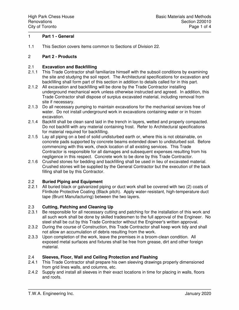
High Park Chess House Basic Materials and Methods Renovations Section 220010 City of Toronto Page 1 of 4
T.W.A. Engineering Inc. January 2020
1 Part 1 - General 1.1 This Section covers items common to Sections of Division 22. 2 Part 2 - Products 2.1 Excavation and Backfilling 2.1.1 This Trade Contractor shall familiarize himself with the subsoil conditions by examining
the site and studying the soil report. The Architectural specifications for excavation and backfilling shall form part of this section in addition to details called for in this part.
2.1.2 All excavation and backfilling will be done by the Trade Contractor installing underground mechanical work unless otherwise instructed and agreed. In addition, this Trade Contractor shall dispose of surplus excavated material, including removal from site if necessary.
2.1.3 Do all necessary pumping to maintain excavations for the mechanical services free of water. Do not install underground work in excavations containing water or in frozen excavation.
2.1.4 Backfill shall be clean sand laid in the trench in layers, wetted and properly compacted. Do not backfill with any material containing frost. Refer to Architectural specifications for material required for backfilling.
2.1.5 Lay all piping on a bed of solid undisturbed earth or, where this is not obtainable, on concrete pads supported by concrete beams extended down to undisturbed soil. Before commencing with this work, check location of all existing services. This Trade Contractor is responsible for all damages and subsequent expenses resulting from his negligence in this respect. Concrete work to be done by this Trade Contractor.
2.1.6 Crushed stones for bedding and backfilling shall be used in lieu of excavated material. Crushed stones will be supplied by the General Contractor but the execution of the back filling shall be by this Contractor.
2.2 Buried Piping and Equipment 2.2.1 All buried black or galvanized piping or duct work shall be covered with two (2) coats of
Flintkote Protective Coating (Black pitch). Apply water-resistant, high-temperature duct tape (Brunt Manufacturing) between the two layers.
2.3 Cutting, Patching and Cleaning Up 2.3.1 Be responsible for all necessary cutting and patching for the installation of this work and
all such work shall be done by skilled tradesmen to the full approval of the Engineer. No steel shall be cut by this Trade Contractor without the Engineer's written approval.
2.3.2 During the course of Construction, this Trade Contractor shall keep work tidy and shall not allow an accumulation of debris resulting from the work.
2.3.3 Upon completion of the work, leave the premises in a broom-clean condition. All exposed metal surfaces and fixtures shall be free from grease, dirt and other foreign material.
2.4 Sleeves, Floor, Wall and Ceiling Protection and Flashing 2.4.1 This Trade Contractor shall prepare his own sleeving drawings properly dimensioned
from grid lines walls, and columns, etc. 2.4.2 Supply and install all sleeves in their exact locations in time for placing in walls, floors
and roofs.

High Park Chess House Basic Materials and Methods Renovations Section 220010 City of Toronto Page 2 of 4
T.W.A. Engineering Inc. January 2020
2.4.3 Sleeve size, unless otherwise noted, leave 13mm (1/2") clearance around the pipes or, when the pipe is insulated, around the pipe insulation. Openings around the pipes and insulated pipes shall be tightly packed with fiberglass insulation and caulked around the edges with an approved fire-rated compound. All openings shall be sealed.
2.4.4 Sleeves set in interior concrete slabs and walls, masonry walls and other fire-rated partitions, shall be packed with rock wool and sealed with fire-rated compound. All assembly shall be suitable to withstand high temperatures as stipulated in the Ontario Building Code.
2.4.5 All vent pipes extending through the roof shall be flashed with 0.454 Kg (16 oz.) copper or 1.81 Kg (4 lb.) lead flashing about 609mm X 609mm (24" X 24") and dressed over hub and caulked into place. Provide vent extension above roof height as required or minimum 615mm (24") high. Other piping or ducts passing through the roof shall be provided with curbs and flashing.
2.5 Anchors, Hangers and Equipment Supports 2.5.1 Design pipe anchors to restrain the movement of pipes in all directions. Take special
care to avoid introduction of undue reaction forces into the structure of the building to flanges of pumps and equipment, to expansion joints and to the pipe.
2.5.2 Install all piping securely supported from hangers or supports in a manner to ensure that the building construction is not weakened or over-stressed: that pipes are secure, vibration-free, free to expand and contract and properly graded, and that the vertical adjustment of the horizontal piping is possible after erection.
2.5.3 Pipe hangers shall be of the adjustable wrought clevis type. Do not use pipe hooks, chains or perforated strips. Install copper pipe with 3.2mm (1/8") thickness of di-electric packing between pipe and support, or install copper hangers.
2.5.4 For horizontal piping, except sprinkler piping or unless otherwise noted, space hangers not more than:
2.5.4.1 2.438 M (8') apart for piping 19mm (3/4") diam. and smaller. 2.5.4.2 3.657 M (12') for piping 25mm (1") to 51mm (2") diameter. 2.5.4.3 4.572 M (15') for piping 64mm (2½") and larger. 2.5.5 All concrete work including the forming and supply of concrete necessary for support of
any mechanical equipment and materials, shall be done by the respective Trade Contractor installing the equipment.
2.6 Vibration and Sound Control 2.6.1 Isolate all mechanical equipment adequately from building structure and from other
equipment, piping, ductwork, etc. to maintain a sound level not exceeding in any Octave Band 35 NC level.
2.6.2 All electrical connections to vibrating equipment shall be flexible and looped one turn. 2.6.3 All hardware of vibration isolators shall be zinc chromate plated. All hardware installed
outdoors or exposed to high humidity conditions shall have two (2) coats of rust preventing paint. Springs shall be neoprene coated.
2.6.4 Submit vibration isolator shop drawings for review and approval before installation. 2.7 Access Doors 2.7.1 Metal access doors of same fire rating as walls and ceilings in which they are installed
shall be supplied by this Trade Contractor and installed by the Sub Contractor unless otherwise noted. Access door to be by Acudor or approved equal UF-5000 series for non rated wall or ceiling & FW-5050 series for fire rated wall or ceiling. For tile walls use
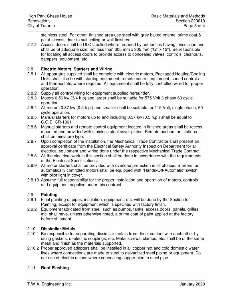
High Park Chess House Basic Materials and Methods Renovations Section 220010 City of Toronto Page 3 of 4
T.W.A. Engineering Inc. January 2020
stainless steel. For other finished area use steel with grey baked enamel prime coat & paint access door to suit ceiling or wall finishes.
2.7.2 Access doors shall be ULC labelled where required by authorities having jurisdiction and shall be of adequate size, not less than 305 mm x 305 mm (12" x 12"). Be responsible for locating all access doors to provide access to concealed valves, controls, cleanouts, dampers, equipment, etc.
2.8 Electric Motors, Starters and Wiring 2.8.1 All apparatus supplied shall be complete with electric motors, Packaged Heating/Cooling
Units shall also be with starting equipment, remote control equipment, speed controls and thermostats, where required. All equipment shall be fully controlled wired for proper operation.
2.8.2 Supply all control wiring for equipment supplied hereunder. 2.8.3 Motors 0.56 kw (3/4 h.p) and larger shall be suitable for 575 Volt 3 phase 60 cycle
operation. 2.8.4 All motors 0.37 kw (0.5 h.p.) and smaller shall be suitable for 115 Volt, single phase, 60
cycle operation. 2.8.5 Manual starters for motors up to and including 0.37 kw (0.5 h.p.) shall be equal to
C.G.E. CR-1061. 2.8.6 Manual starters and remote control equipment located in finished areas shall be recess
mounted and provided with stainless steel cover plates. Remote pushbutton stations shall be miniature type.
2.8.7 Upon completion of the installation, the Mechanical Trade Contractor shall present an approval certificate from the Electrical Safety Authority Inspection Department for all electrical equipment and wiring done under the respective Mechanical Trade Contract.
2.8.8 All the electrical work in this section shall be done in accordance with the requirements of the Electrical Specifications.
2.8.9 All motor starters shall be provided with overload protection in all phases. Starters for automatically controlled motors shall be equipped with "Hands-Off-Automatic" switch with pilot light in cover.
2.8.10 Assume full responsibility for the proper installation and operation of motors, controls and equipment supplied under this contract.
2.9 Painting 2.9.1 Final painting of pipes, insulation, equipment, etc. will be done by the Section for
Painting, except for equipment which is specified with factory finish. 2.9.2 Equipment fabricated from steel, such as pumps, tanks, access doors, panels, grilles,
etc. shall have, unless otherwise noted, a prime coat of paint applied at the factory before shipment.
2.10 Dissimilar Metals 2.10.1 Be responsible for separating dissimilar metals from direct contact with each other by
using gaskets, di-electric couplings, etc. Metal screws, clamps, etc. shall be of the same metal and finish as the materials supported.
2.10.2 Proper approved adapters shall be installed in all copper hot and cold domestic water lines where connections are made to steel to galvanized steel piping or equipment. Do not use di-electric unions where connecting copper pipe to steel pipe.
2.11 Roof Flashing

High Park Chess House Basic Materials and Methods Renovations Section 220010 City of Toronto Page 4 of 4
T.W.A. Engineering Inc. January 2020
2.11.1 Cast iron plumbing vents passing through the roof shall be flashed with a 2.72 Kg (6 lb.) lead sheet flashing. Top of hub shall be a minimum of 25 mm (1") and a maximum of 38 mm (1½") above the top of the insulation. After completion of roofing, cut and dress flashing into hub and fix vent extension by lead caulking. Extension is to project a minimum of 305 mm (12") above roof level.
2.11.2 Other piping and conduit extending through roof shall be provided with a 0.454 Kg. (16 oz) copper roof flashing 609 mm (24") square and sleeve extending not less than 305 mm (12") above the roof. Piping shall be provided with a 0.454 Kg (16 oz) copper conical weather drip clamped to the piping with all joints sealed with mastic.
2.11.3 Frame up openings in the roof with curb, cant strip, etc. Flashing of curb will be done by Roofing Section, but supply and install counter flashing to provide a weathertight installation.
2.11.4 Where counter flashing on equipment is aluminum, these Sections shall apply a 3.2 mm (1/8") transite cover nailed over the copper flashing to prevent aluminum to copper contact.
- END OF SECTION 220010 -
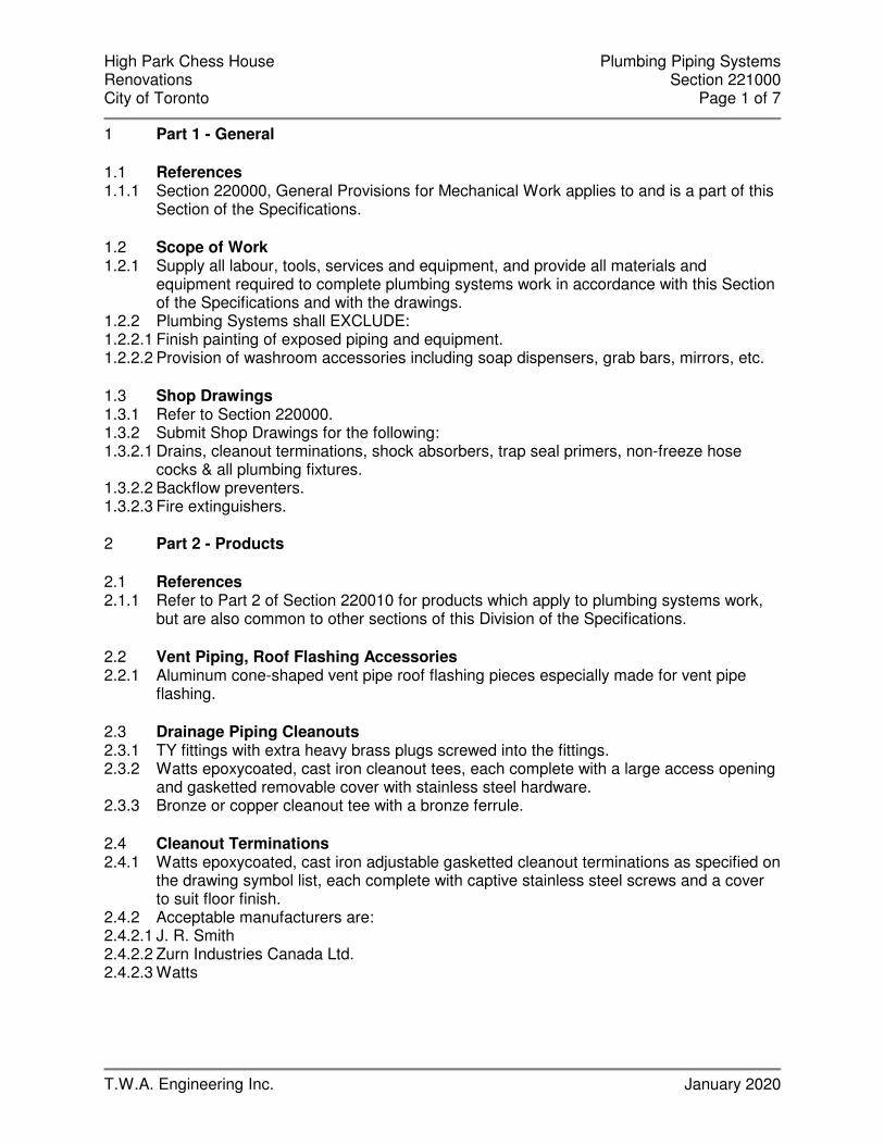
High Park Chess House Plumbing Piping Systems Renovations Section 221000 City of Toronto Page 1 of 7
T.W.A. Engineering Inc. January 2020
1 Part 1 - General 1.1 References 1.1.1 Section 220000, General Provisions for Mechanical Work applies to and is a part of this
Section of the Specifications. 1.2 Scope of Work 1.2.1 Supply all labour, tools, services and equipment, and provide all materials and
equipment required to complete plumbing systems work in accordance with this Section of the Specifications and with the drawings.
1.2.2 Plumbing Systems shall EXCLUDE: 1.2.2.1 Finish painting of exposed piping and equipment. 1.2.2.2 Provision of washroom accessories including soap dispensers, grab bars, mirrors, etc. 1.3 Shop Drawings 1.3.1 Refer to Section 220000. 1.3.2 Submit Shop Drawings for the following: 1.3.2.1 Drains, cleanout terminations, shock absorbers, trap seal primers, non-freeze hose
cocks & all plumbing fixtures. 1.3.2.2 Backflow preventers. 1.3.2.3 Fire extinguishers. 2 Part 2 - Products 2.1 References 2.1.1 Refer to Part 2 of Section 220010 for products which apply to plumbing systems work,
but are also common to other sections of this Division of the Specifications. 2.2 Vent Piping, Roof Flashing Accessories 2.2.1 Aluminum cone-shaped vent pipe roof flashing pieces especially made for vent pipe
flashing. 2.3 Drainage Piping Cleanouts 2.3.1 TY fittings with extra heavy brass plugs screwed into the fittings. 2.3.2 Watts epoxycoated, cast iron cleanout tees, each complete with a large access opening
and gasketted removable cover with stainless steel hardware. 2.3.3 Bronze or copper cleanout tee with a bronze ferrule. 2.4 Cleanout Terminations 2.4.1 Watts epoxycoated, cast iron adjustable gasketted cleanout terminations as specified on
the drawing symbol list, each complete with captive stainless steel screws and a cover to suit floor finish.
2.4.2 Acceptable manufacturers are: 2.4.2.1 J. R. Smith 2.4.2.2 Zurn Industries Canada Ltd. 2.4.2.3 Watts

High Park Chess House Plumbing Piping Systems Renovations Section 221000 City of Toronto Page 2 of 7
T.W.A. Engineering Inc. January 2020
2.5 Drains 2.5.1 Watts epoxy coated, cast iron body drains as specified on the drawing symbol list, each
complete with all required accessories. 2.5.2 Acceptable manufacturers are: 2.5.2.1 J. R. Smith 2.5.2.2 Zurn Industries Canada Ltd. 2.5.2.3 Watts 2.6 Trap Seal Primers 2.6.1 P.P.P. #PTS-6-115V cast bronze body activated by subminiature solenoid valve. 2.6.2 Acceptable manufacturers are: 2.6.2.1 J. R. Smith 2.6.2.2 Zurn Industries Canada Ltd. 2.6.2.3 Watts 2.7 Water Piping Shock Absorbers 2.7.1 P.P.P. Inc. ’SS’ Series all stainless steel construction shock absorbers, each with a pre-
charged air chamber of nesting steel bellows. 2.7.2 Acceptable manufacturers are: 2.7.2.1 J. R. Smith 2.7.2.2 Zurn Industries Canada Ltd. 2.7.2.3 Watts 2.8 Hose Cocks 2.8.1 Hose cocks shall be: 2.8.1.1 In unfinished areas inside the building - Jenkins Canada Inc. #303. 2.8.1.2 In the garbage room – Acon #8121CR. 2.8.1.3 On exterior walls outside building –Watts #HY-725-88 flush mounted non-freeze type as
specified on the drawing symbol list. 2.8.2 Acceptable flush mounted outlet manufacturers are: 2.8.2.1 J. R. Smith 2.8.2.2 Zurn Industries Canada Ltd. 2.8.2.3 Watts 2.9 Water Piping Vacuum Breakers 2.9.1 Watts Regulator of Canada Ltd. #NFB or equal CSA certified vacuum breaker. 2.10 Water Piping Backflow Preventers 2.10.1 Watts Regulator of Canada #9D or equal CSA certified continuous pressure backflow
preventer with a brass body, stainless steel working parts, an integral strainer and an intermediate atmospheric vent.
2.11 Fire Extinguishers 2.11.1 National Fire Equipment Ltd., Model ABC-5 or equal, 2.26 kg, ULC listed and labelled,
2A:10BC rated pressurized dry chemical extinguishers, each complete with a wall mounting bracket and mounting hardware.
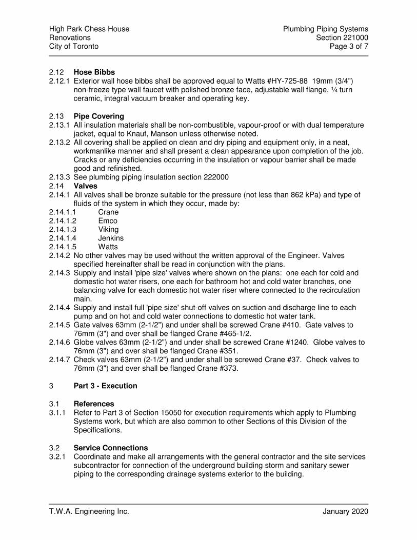
High Park Chess House Plumbing Piping Systems Renovations Section 221000 City of Toronto Page 3 of 7
T.W.A. Engineering Inc. January 2020
2.12 Hose Bibbs 2.12.1 Exterior wall hose bibbs shall be approved equal to Watts #HY-725-88 19mm (3/4")
non-freeze type wall faucet with polished bronze face, adjustable wall flange, ¼ turn ceramic, integral vacuum breaker and operating key.
2.13 Pipe Covering 2.13.1 All insulation materials shall be non-combustible, vapour-proof or with dual temperature
jacket, equal to Knauf, Manson unless otherwise noted. 2.13.2 All covering shall be applied on clean and dry piping and equipment only, in a neat,
workmanlike manner and shall present a clean appearance upon completion of the job. Cracks or any deficiencies occurring in the insulation or vapour barrier shall be made good and refinished.
2.13.3 See plumbing piping insulation section 222000 2.14 Valves 2.14.1 All valves shall be bronze suitable for the pressure (not less than 862 kPa) and type of
fluids of the system in which they occur, made by: 2.14.1.1 Crane 2.14.1.2 Emco 2.14.1.3 Viking 2.14.1.4 Jenkins 2.14.1.5 Watts 2.14.2 No other valves may be used without the written approval of the Engineer. Valves
specified hereinafter shall be read in conjunction with the plans. 2.14.3 Supply and install 'pipe size' valves where shown on the plans: one each for cold and
domestic hot water risers, one each for bathroom hot and cold water branches, one balancing valve for each domestic hot water riser where connected to the recirculation main.
2.14.4 Supply and install full 'pipe size' shut-off valves on suction and discharge line to each pump and on hot and cold water connections to domestic hot water tank.
2.14.5 Gate valves 63mm (2-1/2") and under shall be screwed Crane #410. Gate valves to 76mm (3") and over shall be flanged Crane #465-1/2.
2.14.6 Globe valves 63mm (2-1/2") and under shall be screwed Crane #1240. Globe valves to 76mm (3") and over shall be flanged Crane #351.
2.14.7 Check valves 63mm (2-1/2") and under shall be screwed Crane #37. Check valves to 76mm (3") and over shall be flanged Crane #373.
3 Part 3 - Execution 3.1 References 3.1.1 Refer to Part 3 of Section 15050 for execution requirements which apply to Plumbing
Systems work, but which are also common to other Sections of this Division of the Specifications.
3.2 Service Connections 3.2.1 Coordinate and make all arrangements with the general contractor and the site services
subcontractor for connection of the underground building storm and sanitary sewer piping to the corresponding drainage systems exterior to the building.

High Park Chess House Plumbing Piping Systems Renovations Section 221000 City of Toronto Page 4 of 7
T.W.A. Engineering Inc. January 2020
3.3 Drainage and Vent Piping Installation Requirements 3.3.1 Provide all drainage and vent piping. Pipe shall be as follows:
• Sanitary drainage and vent piping above grade 64mm (2-1/2”) and smaller shall DWV to ASTM B306 with solder joint fittings to CSA B158.1 or ANSI B16.29. 76mm (3”) and larger shall be cast iron pipe and fittings to CSA B70 or alternatively, use K&L hard copper pipe as permitted by code
• Sanitary drains and vent piping buried inside the building 38mm (1-1/2”) and smaller shall be copper tube type L hard to ASTM B88 with solder joint fittings to CSA B158.1 or ANSI B16.29 and for pipe 64mm (2-1/2”) or larger use cast iron hub and spigot soil pipe and fittings to CSA B70 or PVC sewer pipe and fittings to CAN/ CSA-B181.2.
• Storm piping above grade 64mm (2-1/2”) and smaller shall DWV to ASTM B306 with solder joint fittings to CSA B158.1 or ANSI B16.29. 76mm (3”) and larger shall be cast iron pipe and fittings to CSA B70
• Storm drain buried inside the building 76mm (3") and larger shall be PVC sewer pipe and fittings to CAN/ CSA-B181.2.
• Hot water heating supply and return piping 50mm (2”) and smaller shall be black steel ASTM schedule 40, treaded ANSI B36.10. Fittings to be cast iron ASTM A126, 860kPa (WSP), threaded, ANSI B16.4.
3.1.1.1 For drainage pump discharge connections from the pump to & including valve connections - Schedule 40 galvanized steel with screwed/screw on companion flange joints as required.
3.1.2 Unless otherwise noted, slope horizontal drainage piping above ground in sizes to and including 75 diameter 25 in 1.2 M, and pipe 100 diameter and larger 25 in 2.4 M.
3.1.3 Install and slope underground drainage piping to inverts or slopes indicated on the drawings to provide straight and true gradients between the points shown. Verify available slopes before installing the pipes.
3.1.4 Slope horizontal branches of vent piping down towards the fixture to which they connect with a minimum pitch of 25 in 1.2 M.
3.1.5 Provide cleanouts in drainage piping in locations as follows: 3.1.5.1 In the building drain or drains as close as possible to the inner face of the outside wall,
and, if and where a building trap is installed, locate the cleanout on the downstream side of the building trap.
3.1.5.2 At, or as close as practicable to the foot of each drainage stack. 3.1.5.3 At maximum 15 M intervals in horizontal pipe 100mm diameter and smaller. 30M in
horizontal pipe larger then 100mm diameter 3.1.5.4 For pipe inside the building and above ground in sizes to and including 65 diameter -
Type DWV copper. 3.1.6 Cleanouts shall be the same diameter as the pipe in piping to 100 diameter and not less
than 100 in piping larger than 100 diameter. Cleanouts in vertical piping shall be cleanout tees, cast iron in piping 75 diameter and larger, copper or bronze in piping smaller than 75 diameter. Cleanouts in horizontal piping shall consist of TY fittings. Cleanouts in horizontal inaccessible piping such as underground piping shall consist of TY fittings extended up to proper cleanout terminations set flush with the finished floor. In water-proof areas, each termination shall be equipped with a flashing clamp device. Cleanout terminations shall suit the floor finish in the area where they are located. Provide all required cleanout terminations.
3.1.7 Where cleanout terminations occur in finished areas, locate the terminations to the Consultant's direction and arrange piping to suit.
High Park Chess House Plumbing Piping Systems Renovations Section 221000 City of Toronto Page 5 of 7
T.W.A. Engineering Inc. January 2020
3.1.8 Where cleanouts are concealed behind walls or partitions, install the cleanout such that the cover is within 25 of the finished wall or partition.
3.1.9 Furnish a vent pipe roof flashing accessory for each vent pipe penetrating the roof and turn the units over to the roofing trade for installation.
3.4 Installation of Drains 3.4.1 Provide floor, trench, etc. drains where shown or specified on the drawings. 3.4.2 In equipment rooms and similar areas, exactly locate floor drains to suit the layout of
mechanical equipment and location of equipment indirect drainage piping. 3.4.3 In finished areas, confirm the exact location and finish of drains with the Engineer prior
to roughing in. 3.4.4 Equip each drain connected to sanitary drainage piping with a trap. Provide vent piping
and cold water supply piping to drains wherever required by Plumbing Regulations and/or shown on the drawings.
3.4.5 Water supply piping to drains shall consist of soft copper tubing extended from trap seal primers to the floor drain. Provide trap seal primers in domestic cold water piping to the nearest available plumbing fixture.
3.4.6 Provide roof drain bodies in position of flashing into roof construction as part of the roofing work. Install accessories and connect with piping.
3.5 Domestic Hot and Cold Water Piping Installation Requirements 3.5.1 Provide all required domestic hot and cold water piping. Pipe shall be as follows: 3.5.1.1 For underground service pipe to inside the building - centrifugally cast ductile iron or
Manville Canada Inc. 'BLUE BRUTE' rigid PVC. 3.5.1.2 For water service pipe inside the building from termination of the underground main to
and including the water meter connection, meter bypass, future booster pump connections, etc. - Schedule 40 galvanized steel, flanged.
3.5.1.3 For all domestic hot water distribution piping, and for domestic cold water distribution piping inside the building and above ground, except as noted above - Type 'L' hard copper.
3.5.2 Brace and secure underground water service pipe at bend and tees with concrete thrust blocks in accordance with Municipal standards.
3.5.3 Slope all piping so that it can be completely drained. 3.5.4 Provide an accessible manually operated air vent above the high point of each water
piping system unless the systems are suitably vented through frequently used plumbing fixtures or outlets. Automatic air vents will not be permitted except for specific locations approved by the Engineer where the piping will always be under positive pressure.
3.5.5 Provide a vacuum breaker in piping connecting a hose cock or any other fitting to which a hose may be attached.
3.5.6 Provide partition stops with chrome plated access covers for hot and cold water piping to suit washroom fixtures. Locate washroom partition stops under lavatory counters. Partition stops shall be key-operated type. Supply ten (10) keys and turn keys over to the owner upon substantial completion of the work.
3.6 Installation of Hose Cocks 3.6.1 Provide hose cocks where shown on the drawings and connect with piping as indicated. 3.6.2 Locate wall-mounted hose cocks approximately 450mm above the floor or grade unless
otherwise noted on Architectural or Mechanical drawings.

High Park Chess House Plumbing Piping Systems Renovations Section 221000 City of Toronto Page 6 of 7
T.W.A. Engineering Inc. January 2020
3.6.3 Confirm the exact location of all exterior wall mounted hose cocks with the Engineer prior to roughing-in.
3.6.4 Supply six (6) identified loose key operators for exterior hose cocks and hand the operators over to the owner at the site prior to substantial performance of the work.
3.7 Flushing and Disinfection of Domestic Water Piping 3.7.1 Flush domestic water piping until all foreign materials have been removed and flushed
water is clear. Provide connections and pumps as required. Open and close valves, fittings, etc. to ensure thorough flushing.
3.7.2 When flushing has been completed, introduce a strong solution of chlorine into the piping and ensure that it is distributed throughout the entire domestic water systems. Disinfect the piping in accordance with AWWA C601-68. Operate valves, fittings and similar appurtenances while the piping contains strong chlorine solution.
3.7.3 Flush piping of chlorine solution after twenty four (24) hours. 3.7.4 Measure chlorine residuals at the extreme end of each piping system being disinfected.
After an adequate chlorine residual of not less than 50 ppm has been obtained, leave the system for 24 hours. Take further samples to ensure that there is not less than 10 ppm of chlorine residual throughout the systems.
3.7.5 When disinfecting is complete, flush the systems and fill. 3.7.6 Provide certificate or letter confirming the above procedure has been completed. 3.8 Installation of Fire Extinguishers 3.8.1 Supply 2A:10BC rated extinguishers where shown on the drawings. 3.8.2 Wall mount the mounting bracket for each extinguisher. 3.8.3 Turn the extinguishers over to the owner at the site upon substantial completion of the
work. 3.9 Pipes and Fittings 3.9.1 Supply and install all pipework to complete building mechanical system. 3.9.2 Sizes and materials of plumbing pipes and drains shall be in accordance with the
Plumbing Code and with authorities having jurisdiction. 3.9.3 Storm drains above ground larger than 100mm (4" dia.) shall be CSA Class 4000 cast
iron soil pipe and fittings with mechanical joints. 3.9.4 Buried watermains throughout and fire lines under concrete shall be ductile iron pipe
ASA class 2 cement joined where required by local authorities with Tyton joints or Type K copper pipe with couplings.
3.9.5 Connection from galvanized piping to copper piping shall be done using approved type connections to prevent electrolysis.
3.9.6 Cast iron soil pipes shall be complete with MJ fittings or joints with oakum soft pig lead. All lead used for making joints for cast iron shall be new, pure soft pig lead of the best quality. If MJ fittings are used, provide caulking of PC4 compound at offsets only.
3.9.7 Threaded joints shall be carefully reamed and joined with compound on the male thread only.
3.9.8 Proper allowance shall be made on all piping for expansion, elimination of air binding and water hammer. Provide an air chamber at the tope of each riser. Air chambers shall be at least 610mm (24") long and shall be of the maximum pipe size of the supply riser.
High Park Chess House Plumbing Piping Systems Renovations Section 221000 City of Toronto Page 7 of 7
T.W.A. Engineering Inc. January 2020
3.9.9 Connect fixtures separately (unless otherwise noted on soil stack details on plans) on at least three (3) floors before a 90 deg. break in soil stack and run minimum 5m (15') horizontal before connecting to the main sewer to avoid sudsing through fixtures.
- END OF SECTION 221000 -

High Park Chess House Plumbing Piping Insulation Renovations Section 222000 City of Toronto Page 1 of 3
T.W.A. Engineering Inc. January 2020
1 Part 1 - General 1.1 Work Included 1.1.1 Comply with Section 220000, General Requirements and all documents referred to
therein. 1.1.2 Provide all labour, materials, products, equipment and services to supply and install
thermal insulation, vapour barriers and finishes for mechanical work as indicated on the Drawings and specified in this Section of these Specifications.
1.2 Submittals 1.2.1 Submit samples and specification sheets of all types of insulation materials specified in
this Section of the Specifications. 2 Part 2 - Products 2.1 Materials – General 2.1.1 All insulation pertaining to Division 220000 shall be carried out by one firm specializing
in insulation work. 2.1.2 Acceptable insulation manufacturers are Knauf Insulation, Manson Insulation Inc. and
Fiberglas Canada Inc. 2.1.3 Provide insulation and covers in strict accordance with authorities governing
combustibility and fireproofing of materials and in accordance with manufacturer’s recommendations.
2.1.4 Provide non-combustible insulation, jackets and finishes with ULC listed materials having a Flame Spread/Smoke Developed rating of 25/50 or less.
2.1.5 Attain a complete and continuous vapour barrier over insulation applied to cold and dual temperature piping, sheet metal and equipment. Use either factory applied vapour barrier jacket or field applied Reinforced Foil Flame Resistant Kraft vapour barrier jacket. Apply to piping, fittings, valves and inline components, sheet metal and fittings and equipment. Seal longitudinal and circumferential laps with Childers CP82 or Bakelite 230-39 adhesive. If vapour barrier jacket is not lapped, seal joints with self-adhering 100mm [4”] wide plain aluminum foil tape, or adhere 100 mm [4”] wide aluminum foil tape with Childers CP82 or Bakelite 230-39 adhesive. Jacketing with self-adhesive laps and self-adhesive vapour barrier tape will be an acceptable alternative closure system.
2.2 Pipe Insulation 2.2.1 On hot piping applications, hold insulation in place with flare type staples. 2.2.2 On cold and dual temperature piping applications, apply vapour barrier jacket over
insulation and seal longitudinal and circumferential laps with Childers CP82 or Bakelite 230-39 adhesive.
2.2.3 Apply pipe insulation over 40mm [1-1/2”] in thickness in two layers with joints staggered. 2.2.4 Insulate fitting with fabricated mitered or preformed sections of specified insulation. 2.2.5 Insulate over flanges and mechanical couplings with specified insulation and thickness,
sized to suit flange diameters. Fill spaces between insulation and adjoining pipe insulation with similar material.
2.2.6 Insulate valves and inline components with flexible insulation density 12 kg/cubic metre [3/4 lbs./cu. ft.] compressed not more than 50% of original thickness. Build up to specified thickness with approved asbestos free finishing cement.
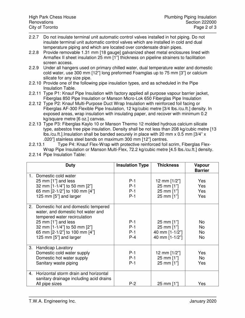
High Park Chess House Plumbing Piping Insulation Renovations Section 222000 City of Toronto Page 2 of 3
T.W.A. Engineering Inc. January 2020
2.2.7 Do not insulate terminal unit automatic control valves installed in hot piping. Do not insulate terminal unit automatic control valves which are installed in cold and dual temperature piping and which are located over condensate drain pipes.
2.2.8 Provide removable 1.31 mm [18 gauge] galvanized sheet metal enclosures lined with Armaflex II sheet insulation 25 mm [1”] thickness on pipeline strainers to facilitation screen access.
2.2.9 Under all hangers used on primary chilled water, dual temperature water and domestic cold water, use 300 mm [12”] long preformed Foamglas up to 75 mm [3”] or calcium silicate for any size pipe.
2.2.10 Provide one of the following pipe insulation types, and as scheduled in the Pipe Insulation Table.
2.2.11 Type P1: Knauf Pipe Insulation with factory applied all purpose vapour barrier jacket, Fiberglas 850 Pipe Insulation or Manson Micro-Lok 650 Fiberglas Pipe Insulation
2.2.12 Type P2: Knauf Multi-Purpose Duct Wrap Insulation with reinforced foil facing or Fiberglas AF-300 Flexible Pipe Insulation, 12 kg/cubic metre [3/4 lbs./cu.ft.] density. In exposed areas, wrap insulation with insulating paper, and recover with minimum 0.2 kg/square metre [6 oz.] canvas.
2.2.13 Type P3: Fiberglas Kaylo 10 or Manson Thermo 12 molded hydrous calcium silicate type, asbestos free pipe insulation. Density shall be not less than 208 kg/cubic metre [13 lbs./cu.ft.].Insulation shall be banded securely in place with 20 mm x 0.5 mm [3/4” x .020”] stainless steel bands on maximum 300 mm [12”] centres.
2.2.13.1 Type P4: Knauf Flex-Wrap with protective reinforced foil scrim, Fiberglas Flex-Wrap Pipe Insulation or Manson Multi-Flex, 72.2 kg/cubic metre [4.5 lbs./cu.ft.] density.
2.2.14 Pipe Insulation Table:
Duty Insulation Type Thickness Vapour Barrier
1. Domestic cold water 25 mm [1”] and less 32 mm [1-1/4”] to 50 mm [2”] 65 mm [2-1/2”] to 100 mm [4”] 125 mm [5”] and larger
P-1 P-1 P-1 P-1
12 mm [1/2”] 25 mm [1”] 25 mm [1”] 25 mm [1”]
Yes Yes Yes Yes
2. Domestic hot and domestic tempered water, and domestic hot water and tempered water recirculation 25 mm [1”] and less 32 mm [1-1/4”] to 50 mm [2”] 65 mm [2-1/2”] to 100 mm [4”] 125 mm [5”] and larger
P-1 P-1 P-1 P-4
25 mm [1”] 25 mm [1”]
40 mm [1-1/2”] 40 mm [1-1/2”]
No No No No
3. Handicap Lavatory Domestic cold water supply Domestic hot water supply Sanitary waste piping
P-1 P-1 P-1
12 mm [1/2”] 25 mm [1”] 25 mm [1”]
Yes No Yes
4. Horizontal storm drain and horizontal sanitary drainage including acid drains All pipe sizes
P-2
25 mm [1”]
Yes
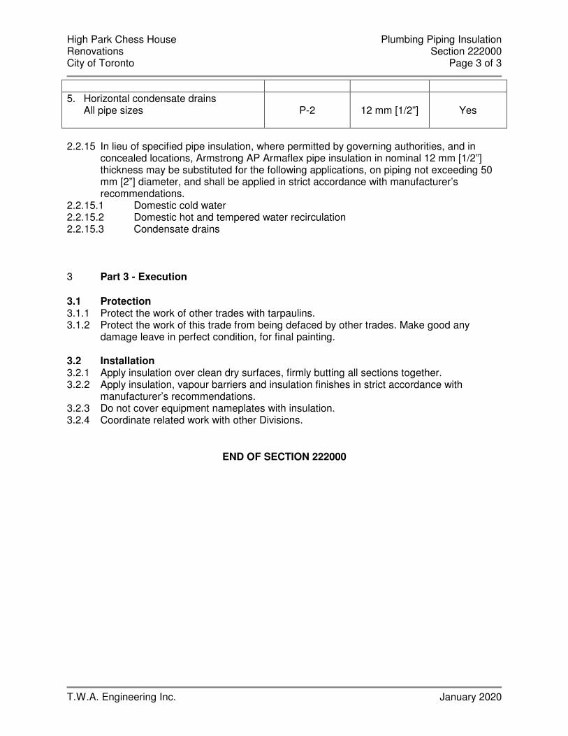
High Park Chess House Plumbing Piping Insulation Renovations Section 222000 City of Toronto Page 3 of 3
T.W.A. Engineering Inc. January 2020
5. Horizontal condensate drains
All pipe sizes
P-2
12 mm [1/2”]
Yes
2.2.15 In lieu of specified pipe insulation, where permitted by governing authorities, and in
concealed locations, Armstrong AP Armaflex pipe insulation in nominal 12 mm [1/2”] thickness may be substituted for the following applications, on piping not exceeding 50 mm [2”] diameter, and shall be applied in strict accordance with manufacturer’s recommendations.
2.2.15.1 Domestic cold water 2.2.15.2 Domestic hot and tempered water recirculation 2.2.15.3 Condensate drains
3 Part 3 - Execution 3.1 Protection 3.1.1 Protect the work of other trades with tarpaulins. 3.1.2 Protect the work of this trade from being defaced by other trades. Make good any
damage leave in perfect condition, for final painting.
3.2 Installation 3.2.1 Apply insulation over clean dry surfaces, firmly butting all sections together. 3.2.2 Apply insulation, vapour barriers and insulation finishes in strict accordance with
manufacturer’s recommendations. 3.2.3 Do not cover equipment nameplates with insulation. 3.2.4 Coordinate related work with other Divisions.
END OF SECTION 222000
High Park Chess House Plumbing Fixtures and Fittings Renovations Section 224000 City of Toronto Page 1 of 2
T.W.A. Engineering Inc. January 2020
1 Part 1 - General 1.1 References 1.1.1 Section 220000, General Provisions for Mechanical Work applies to and is a part of this
Section of the Specifications. 1.2 Scope of Work 1.2.1 Supply all labour, tools, services and equipment, and provide all materials and
equipment required to complete plumbing fixture and fitting work in accordance with this section of the specification and the plumbing fixture schedule on the drawings.
1.2.2 Plumbing Fixtures and Fitting work shall exclude: 1.2.2.1 Provision of counters for all counter mounted sinks and lavatories. 1.2.2.2 Provision of washroom accessories, including grab bars. 1.2.2.3 Provision of access doors in building surfaces. 1.2.2.4 Finish painting of exposed piping. 1.3 Shop Drawings 1.3.1 Refer to Section 220000. 1.3.2 Submit shop drawings for all plumbing fixtures and trim. 2 Part 2 - Products 2.1 References 2.1.1 Refer to Section 220010 for products that apply to plumbing fixture and fitting work, but
are also common to other sections of this Division of the Specifications. Refer to mechanical drawing equipment schedule section for fixture type and make.
2.2 Acceptable Plumbing Fixture and Fitting Manufacturers 2.2.1 Acceptable manufacturers of plumbing fixtures and fittings are as follows: 2.2.1.1 Water Closets, Lavatories, Counter Mounted Sinks: American Standard, Franke. 2.2.1.2 Lavatory, Sink, Shower supply fittings: American Standard, Chicago Faucet, 3 Part 3 - Execution 3.1 References 3.1.1 Provide all required plumbing fixtures and fittings. 3.1.2 Connect plumbing fixtures and fittings with piping in accordance with the following
schedule:
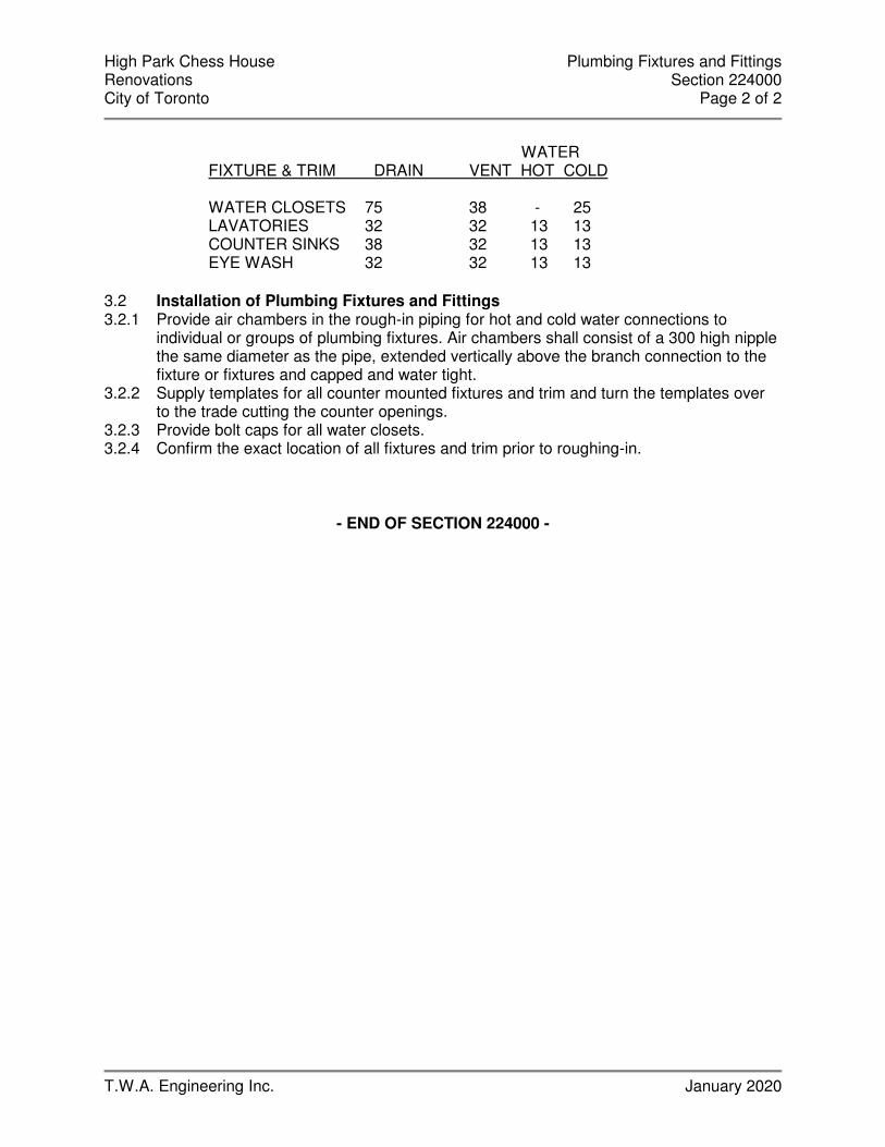
High Park Chess House Plumbing Fixtures and Fittings Renovations Section 224000 City of Toronto Page 2 of 2
T.W.A. Engineering Inc. January 2020
WATER
FIXTURE & TRIM DRAIN VENT HOT COLD
WATER CLOSETS 75 38 - 25 LAVATORIES 32 32 13 13 COUNTER SINKS 38 32 13 13 EYE WASH 32 32 13 13
3.2 Installation of Plumbing Fixtures and Fittings 3.2.1 Provide air chambers in the rough-in piping for hot and cold water connections to
individual or groups of plumbing fixtures. Air chambers shall consist of a 300 high nipple the same diameter as the pipe, extended vertically above the branch connection to the fixture or fixtures and capped and water tight.
3.2.2 Supply templates for all counter mounted fixtures and trim and turn the templates over to the trade cutting the counter openings.
3.2.3 Provide bolt caps for all water closets. 3.2.4 Confirm the exact location of all fixtures and trim prior to roughing-in.
- END OF SECTION 224000 -

High Park Chess House HVAC Air Distribution Renovations City of Toronto Section 233000 Page 1 of 6
T.W.A. Engineering Inc. January 2020
1 Part 1 - General 1.1 References 1.1.1 Section230000, General Provisions for Mechanical Work applies to and is a part of this
Section of the Specifications. 1.2 Scope of Work 1.2.1 Supply all labour, materials, products, equipment and services to supply and install the
sheet metal and ductwork systems as indicated on the drawings and specified in this section of the specifications.
1.3 Reference Standards 1.3.1 Meet Standards described in the latest SMACNA Standards. 1.3.2 Duct dimensions shown on Drawings are net, inside insulation and acoustic duct lining. 1.3.3 Combination fire and smoke dampers and fire dampers shall be ULC listed and labeled,
and meet requirements of Ontario Fire Marshall and NFPA – 90A. 2 Part 2 - Products 3.3 Ductwork
2..1 Fabricate ductwork from galvanized sheet metal unless other materials are specifically
named. Duct installation shall conform to the following: 1. Ductwork shall be smooth on the inside and free of obstructions, vibration and rattle. 2. Fabricate ductwork, accept as described in the next item, according to the following
classifications – 1. Low pressure: Velocities less than 10 m/s (2000fpm) and static pressure in duct
less than 500 Pa (2 in. w. g.) , positive or negative 2. Medium Pressure: Velocities 10 m / s (2000 fpm) and greater and static pressure
in duct from 500 Pa (2 in. w. g. ) positive or negative to 750 Pa (3 in w.g.) positive or negative and up to 1500 Pa (6 in w. g.) positive
3. High Pressure: Velocities 10 m / s (2000 fpm) and greater and static pressure in duct over 1500 Pa (6 in w. g.) positive up to 2500 Pa (10 in w. g. ) positive
3. Provide medium pressure duct construction for –
1. Ductwork between air handling units and air terminal control u nits, on discharge sides of ventilation air makeup units, and on supply air ductwork of all constant volume air handling units.
2. Ductwork used in smoke exhaust systems
4. Provided duct transformation with expansion fittings having slopes not exceeding 1 to 7 and contraction fittings having slopes not exceeding 1 to 4 5. Provide a full radius tees, bends, and elbows for changes in direction except where square elbows are required due to space restrictions. Provide DuroDyne double thickness 0.8 mm (24 ga.) turning vanes assembled in top and bottom rails in square elbows. 6. Provide balancing dampers free to move in either direction without binding and
High Park Chess House HVAC Air Distribution Renovations City of Toronto Section 233000 Page 2 of 6
T.W.A. Engineering Inc. January 2020
rattling. Construct dampers in low and medium pressure ductwork from 1. 2 mm (18 gauge) galvanized sheet metal. Use manual quadrants on small ducts. On dampers longer than 375 mm (15 “) use push rods with DuroDyne Model SRP ball joints. Use two push rods on ducts wider than 600 mm (24”) 7. Isolate equipment with DuroDyne neoprene 0.* mm (0.32 “) thick flexible connectors with finished fabric width not less than 150 mm (6”) 8. Provide 50 mm (2 “) insulated sheet metal blank off panels behind unused portions of exterior louvers. 9. Seal all joints in low, medium and high pressure supply air ductwork with Transcontinential MP for low and medium pressure or DuroDyne S2 duct sealer for high pressure.
2..2 Construct round ductwork to meet high pressure duct standard and as follows –
1. Provide welded sleep joint construction round duct fittings. Wipe pipe and fittings with DuroDyne S2 duct sealer before assembly. Secure joints with self-tapping screws, then brush again with thick coat of duct sealer.
2. Provide dieformed round elbows through 200 mm (8”0 dia. Constructed from 1.1 Mm (20 gauge) galvanized steel. Provide 5 section construction for larger elbows.
3. Provide conical round tees. 2..3 Flexible ductwork–
1. Provide Flexmaster Triple Lock Aluminum, flexible ductwork upstream and
downstream of air terminal control units and / or other locations indicated on the Drawings.
2. Construct ductwork from a tape of soft annealed aluminum sheet, spiral would into a tube and spiral corrugated to provide strength and flexibility. Provide a triple mechanical lock to form a continuous secure air joint without the use of adhesives for pressures up to 3000 Pa (12”).
3. Conform to the requirements of NFPA 90 and Underwriters Laboratories classification for round duct to specifications 181.
2..4 Aluminum Ductwork –
1. Provide 3003 – H14 aluminum ductwork for the following systems – 1. Washroom exhaust
2. Construct aluminum ductwork in accordance with equivalent standards to the galvanized steel outlined in the SMACNA handbook.
3.3 Access Doors
2..1 Provide access doors for galvanized ductwork using 0.7 mm (24 gauge) galvanized
material with galvanized mounting frame and 25 mm (1”) rigid insulation between panels. Provide fastening devices to give tight closure.
High Park Chess House HVAC Air Distribution Renovations City of Toronto Section 233000 Page 3 of 6
T.W.A. Engineering Inc. January 2020
2..2 Provide access doors for stainless steel ductwork using 0.61 mm (24 gauge) stainless steel with stainless steel mounting frame and 25 mm (1 “) rigid insulation between panels. Provide fastening devices to give tight closure.
2..3 Provide access doors for aluminum ductwork of 0.61 mm (24 gauge) aluminum with rigid insulation between panels. Provide fastening devices to give tight closure.
2..4 Provide access doors and removable panels in plenums and casings of 1.31 mm (18 gauge) galvanized material with 50 mm (2 “) thickness fiberglass insulation. Equip doors with handles and hinges to open from either side (without risk of injury) as follows –
1. For mandoors –
1. Handles – Durodyne SP – 20 2. Hinges – Durodyne HB – 3 3. Gaskets – durodyne GN – 22
2. For removable panels –
1. Sash locks – Durodyne SL – 1 2. Gaskets – Durodyne GN – 22
2..5 Construct all access doors with double panels. 2..6 Provide neoprene gaskets securely formed into door frames around the periphery of all
ducts access doors. 2..7 Equip door frames for plenums and casings with hollow tubular gaskets. 3.3 Acoustic Duct Lining
2..1 Provide 25 Mm (1 “) thick fiberglass rigid coated duct liner, not less than 72.1 kg / cubic
metre (4.5 psf) density. Adhere liner with coated side towards the air stream, with 100% covering of Benjamin Foster 85-20 or Bakelite 230-38 adhesive, and mechanical fasteners at not greater than 400 mm (16 “) centres, on all four surfaces
3.3 Field Assembled Plenum and Casing Construction
2..1 Provide metal partitions, plenums and casings of not less than 1.61 mm (16 gauge)
galvanized sheet metal suitably reinforced with rolled angle sections. 2..2 Provide metal partitions, plenums and casings with adequate strength for all operating
conditions. Fabricate each sheet or material as a panel. Join panels by 40 mm (1.5 “) standing seams on outside of casings and secure with bolts at 300 mm (12 “) centres.
2..3 Provide closure baffles around banks of coils, filters and other inline components. 2..4 Provide 25 mm (1”) minimum size rolled structural steel angles where casing meets
floor. Caulk joints to prevent air and water leakage. 2..5 Flange and bolt casings on 150 mm (6”) centres to coils, blankoff panels and filler
panels. 2..6 Incorporate adjustable directional flow baffles into mixing plenums, to ensure complete
mixing of outdoor and return air streams with stratification not to exceed + - 2 C (+ - 4 F) across the coil face at winter outdoor design temperature.
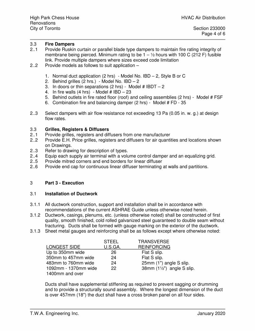
High Park Chess House HVAC Air Distribution Renovations City of Toronto Section 233000 Page 4 of 6
T.W.A. Engineering Inc. January 2020
3.3 Fire Dampers 2..1 Provide Ruskin curtain or parallel blade type dampers to maintain fire rating integrity of
membrane being pierced. Minimum rating to be 1 – ½ hours with 100 C (212 F) fusible link. Provide multiple dampers where sizes exceed code limitation
2..2 Provide models as follows to suit application –
1. Normal duct application (2 hrs) - Model No. IBD – 2, Style B or C 2. Behind grilles (2 hrs.) - Model No. IBD – 2 3. In doors or thin separations (2 hrs) - Model # IBDT – 2 4. In fire walls (4 hrs) - Model # IBD – 23 5. Behind outlets in fire rated floor (roof) and ceiling assemblies (2 hrs) - Model # FSF 6. Combination fire and balancing damper (2 hrs) - Model # FD - 35
2..3 Select dampers with air flow resistance not exceeding 13 Pa (0.05 in. w. g.) at design
flow rates. 3.3 Grilles, Registers & Diffusers 2..1 Provide grilles, registers and diffusers from one manufacturer 2..2 Provide E.H. Price grilles, registers and diffusers for air quantities and locations shown
on Drawings. 2..3 Refer to drawing for description of types. 2..4 Equip each supply air terminal with a volume control damper and an equalizing grid. 2..5 Provide mitred corners and end borders for linear diffuser 2..6 Provide end cap for continuous linear diffuser terminating at walls and partitions.
3 Part 3 - Execution 3.1 Installation of Ductwork
3.1.1 All ductwork construction, support and installation shall be in accordance with
recommendations of the current ASHRAE Guide unless otherwise noted herein. 3.1.2 Ductwork, casings, plenums, etc. (unless otherwise noted) shall be constructed of first
quality, smooth finished, cold rolled galvanized steel guaranteed to double seam without fracturing. Ducts shall be formed with gauge marking on the exterior of the ductwork.
3.1.3 Sheet metal gauges and reinforcing shall be as follows except where otherwise noted: STEEL TRANSVERSE LONGEST SIDE U.S.GA. REINFORCING Up to 350mm wide 26 Flat S slip. 350mm to 457mm wide 24 Flat S slip. 483mm to 760mm wide 24 25mm (1") angle S slip. 1092mm - 1370mm wide 22 38mm (1½") angle S slip. 1400mm and over
Ducts shall have supplemental stiffening as required to prevent sagging or drumming and to provide a structurally sound assembly. Where the longest dimension of the duct is over 457mm (18") the duct shall have a cross broken panel on all four sides.

High Park Chess House HVAC Air Distribution Renovations City of Toronto Section 233000 Page 5 of 6
T.W.A. Engineering Inc. January 2020
3.1.4 Radius of elbows shall be at least 1-1/2 times the width of the duct. Where this is not possible due to space limitation, use double thickness turning vanes the full height of the duct. Where cross section changes occur limit expansion in the direction of air flow 30 degree angle and contraction to 40 degree angle. Use guide vanes where this is not possible.
3.1.5 All ducts shall be adequately supported with 25mm (1")x 14 ga. iron bands extending down the full height of the duct, returned under duct and fastened with galvanized sheet metal screws. Ducts 635mm (25") to 914mm (36") with 32mm x 32mm x 3mm (1¼ x 1¼ x 1/8) galvanized angle with 7mm (1/4") rod. Ducts 940mm (37") to 1829mm (72") with 38mm x 38mm x 3mm (1½ x 1½ x 1/8") galvanized angle with 10mm (3/8") rod. Hangers shall not be more than 2.438m (8') apart for ducts up to 457mm (18") width and not more than 1.219m (4') apart for ducts greater than 457mm (18") in width. Nails shall not be driven through the duct walls.
3.1.6 Joints shall be made air tight and securely fastened. Slip joints shall have a lap of at least 25mm (1") and shall be fastened individually.
3.1.7 Frame and install motorized dampers. Unless shown otherwise, attach each motorized damper module to the channel framing.
3.1.8 Provide frames in ductwork for air flow stations 3.1.9 Provide DuroDyne IP–1 or IP–2 test openings in all ducts entering and leaving air
handling equipment. Install test openings at 150 mm (6”) intervals across the long dimension of rectangular ducts, and at 90 degree intervals around circular ducts. In insulated surfaces, provide extension to suit insulation thickness. Provide additional Model IP – 4 test ports in ductwork where required for air balancing. Submit drawings to indicate proposed locations.
3.1.10 Provide acoustic insulation on supply air ductwork for 3000 mm (10 ft) in each direction from discharge side of mechanical unit ventilator
3.1.11 Provide a sheet metal protection for leading edge of acoustic insulation 3.1.12 Provide neoprene isolation gaskets and nylon bolts at connections required for dissimilar
metals. 3.1.13 Seal water tight all longitudinal and transverse joints in ductwork for washroom exhaust
systems. 3.1.14 Seal water tight bottom and sides of intake and exhaust ducts connected to exterior
louvers as follows-
1. Intake – from Louvre to air handling unit. 2. Exhaust – from Louvre to 2 metres (6’ – 6 “) upstream of Louvre
3.2 Installation of Fire Dampers 3.2.1 Install dampers in approved manner suitably anchored to building structure in locations
indicated on the Drawings 3.2.2 Install fire dampers complete with sleeve and full perimeter steel angle on both sides of
barrier being pierced. Provide manufacturers recommended minimum combustible frame and sleeve. Sleeve blades pocketed outside of air stream.
3.2.3 Divide openings into smaller openings using fire resistant structures where openings to be protected require dampers larger than maximum UL listed sizes.

High Park Chess House HVAC Air Distribution Renovations City of Toronto Section 233000 Page 6 of 6
T.W.A. Engineering Inc. January 2020
3.3 Installation of Grilles, Registers & Diffusers 3.3.1 Provide air terminals in strict accordance with manufacturer’s recommendations and
final reflected ceiling plans. 3.3.2 Provide plaster frames for units installed in plaster finishes. Fit frames tightly to prevent
leakage and smudging 3.4 Testing 3.4.1 Pressure test medium and high pressure ductwork to demonstrate leakage is 5% or less
of the sum of all connected outlets. 3.4.2 Test medium pressure duct at 1500 Pa (6in. w.g.) and high pressure duct at 2500 Pa
(10 in w.g.) static pressure. 3.4.3 Repair duct and retest where air leakage exceeds the specified limit. 3.4.4 Make good all audible leakage, whether test is within 5% limit or not 3.4.5 Provide calibrated tester, connection hoses, block ends, etc., as required 3.5 Clean Up 3.5.1 Vacuum clean the inside of all air handling systems, including fans, plenums, duts, coils
and terminal units to ensure that they are free from debris and dust.
- END OF SECTION 233000-
High Park Chess House Sheet Metal Insulation Renovations City of Toronto Section 234000 Page 1 of 3
T.W.A. Engineering Inc. January 2020
1 Part 1 - General 1.1 Work Included 1.1.1 Comply with Division 230000, General Requirements and all documents referred to
therein. 1.1.2 Provide all labour, materials, products, equipment and services to supply and install
thermal insulation, vapour barriers and finishes for mechanical work as indicated on the Drawings and specified in this Section of these Specifications.
1.2 Submittals 1.2.1 Submit samples and specification sheets of all types of insulation materials specified in
this Section of the Specifications. 2 Part 2 - Products 2.1 Materials – General 2.1.1 All insulation pertaining to Division 230000 shall be carried out by one firm specializing
in insulation work. 2.1.2 Acceptable insulation manufacturers are Knauf Insulation, Manson Insulation Inc and
Fiberglas Canada Inc. 2.1.3 Provide insulation and covers in strict accordance with authorities governing
combustibility and fireproofing of materials and in accordance with manufacturer’s recommendations.
2.1.4 Provide non-combustible insulation, jackets and finishes with ULC listed materials having a Flame Spread/Smoke Developed rating of 25/50 or less.
2.1.5 Attain a complete and continuous vapour barrier over insulation applied to cold and dual temperature piping, sheet metal and equipment. Use either factory applied vapour barrier jacket or field applied Reinforced Foil Flame Resistant Kraft vapour barrier jacket. Apply to piping, fittings, valves and inline components, sheet metal and fittings and equipment. Seal longitudinal and circumferential laps with Childers CP82 or Bakelite 230-39 adhesive. If vapour barrier jacket is not lapped, seal joints with self-adhering 100mm [4”] wide plain aluminum foil tape, or adhere 100 mm [4”] wide aluminum foil tape with Childers CP82 or Bakelite 230-39 adhesive. Jacketing with self-adhesive laps and self-adhesive vapour barrier tape will be an acceptable alternative closure system.
2.2 Sheet Metal Insulation 2.2.1 Prior to finishing of insulation of hot and cold exposed rectangular ductwork, provide
corner beads similar to Roll-on Type. 2.2.2 Apply vapour barrier over insulation on cold and dual temperature ducts. 2.2.3 Circular silencers and acoustic plenums need not be externally insulated. 2.2.4 Ductwork and casings linked with acoustic insulation 25 mm [1”] or more in thickness
need not be externally insulated. 2.2.5 Provide one of the following external sheet metal insulation types, and as scheduled in
the Sheet Metal Insulation Table. 2.2.5.1 Type D1: Fiberglas Rigid Duct Insulation, Knauf Rigid Insulation Board or Manson 800
Series Spin-Glas Rigid Insulation Board, not less than 48 kg/cubic metre [3 lbs./cu.ft.] density. Impale insulation on mechanically fastened pins located at not greater than 300 mm [12”] centres. Secure insulation with speed washers.

High Park Chess House Sheet Metal Insulation Renovations City of Toronto Section 234000 Page 2 of 3
T.W.A. Engineering Inc. January 2020
2.2.5.2 Type D2: Fiberglas Flexible Duct Insulation, Knauf Duct Wrap or Manson Microlite Duct Wrap, Manson Microlite Duct Wrap, 12 kg/cubic metre [3/4 lbs./cu.ft.] density. Adhere insulation to duct surface with Childers CP82 or Bakelite 230-39 adhesive, which shall be applied in strips 150 mm [6”] wide at not greater than 300 mm [12”] centres. Lap all edges at least 50 mm [2”] and secure insulation with fire resistant tying cord, similar to Fiberglas EC9-4-T.Take care that insulation is not compressed to less than specified thickness. It is recognized that some compression of insulation will take place immediately under typing cord, but in no case shall the thickness of the compressed material be less than 75% of original specified thickness.
2.2.5.3 Type D3: Fiberglas Rigid Vapour Seal Duct Insulation, Knauf Rigid Insulation Board with FSK facing or Manson Spin-Glas Rigid Insulation Board with reinforced foil facing. Density shall not be less than 48 kg/cubic metre [3 lbs./cu.ft.]. Impale on mechanically fastened pins located at not greater than 300 mm [12”] centres. Secure with speed washers. Butt joints tightly together and seal washers, breaks and joints with self-adhering 100 mm [4”] wide plain aluminum tape, or adhere foil with Childers CP82 or Bakelite 230-39 adhesive.
2.2.5.4 Type D4: Fiberglas Flexible Duct Insulation, Knauf Duct Wrap or Manson Microlite Insulation, 12 kg/cubic metre [3/4 lbs./cu.ft.] density with factory applied reinforced foil facing. Adhere insulation with Childers CP82 or Bakelite 230-39 adhesive, which shall be applied in strips 150 mm [6”] wide at not greater than 300 mm [12”] centres. Butt edges of insulation tightly together, and seal breaks and joints of facing with self-adhering 100 mm [4”] wide aluminum tape or adhere foil with Childers CP82 or Bakelite 230-39 adhesive.
2.2.6 Sheet Metal Insulation Table:
Duty Insulation Type Thickness Vapour Barrier
1. Panels behind unused portion of louvres
D-3 50 mm [2”] Yes
2. Outside air plenums and ducts D-3 50 mm [2”] Yes
3. Mixed air plenums and ducts D-3 40 mm [1-1/2”] Yes
4. Relief and exhaust air plenums D-3 40 mm [1-1/2”] Yes
5. Exhaust ducts between motorized dampers and building exterior or final 3 m [10 ft] of exhaust air ducts, whichever is greater
D-3 25 mm [1”] Yes
6. Rectangular hot supply ducts D-1 25 mm [1”] No 7. Round hot supply ducts D-2 25 mm [1”] No 8. Exposed rectangular cold and
dual temperature supply ducts D-3 25 mm [1”] Yes
9. Exposed round cold and dual temperature supply ducts
D-3 25 mm [1”] Yes
10. Concealed supply air, (including ducts in shafts) to air terminal control units, excluding flexible ducts.
D-4 25 mm [1”] Yes
11. Free standing supply fan casings D-3 25 mm [1”] Yes

High Park Chess House Sheet Metal Insulation Renovations City of Toronto Section 234000 Page 3 of 3
T.W.A. Engineering Inc. January 2020
12. Air conditioning unit casings D-3 25 mm [1”] Yes
13. Field fabricated casings D-3 40 mm [1-1/2”] Yes
- END OF SECTION 234000 -
High Park Chess House Fans Renovations City of Toronto Section 235010 Page 1 of 2
T.W.A. Engineering Inc. January 2020
1 Part 1 - General 1.1 References 1.1.1 Section230000, General Provisions for Mechanical Work applies to and is a part of this
Section of the Specifications. 1.2 Scope of Work 1.2.1 Supply all labour, materials, tools and equipment required to complete the installation
and testing in accordance with the full intent of the drawings and specifications. The work generally consists of, but is not limited to the following:
1.2.1.1 Exhaust Systems 1.2.1.2 Vibration Isolation 1.2.1.3 Counter Flashing 1.2.1.4 Complete Control System including Control Wiring 1.2.1.5 Balancing and Testing of System 1.2.1.6 Permits to Make Installation 1.2.2 NOTE: All equipment and accessories associated with this system and requirements
such as balancing, shall be as specified in all applicable sections of these specifications. 2 Part 2 - Products 2.1 Reference Standards 2.1.1 Fans to be standard products, selected from published literature of manufacturer. 2.1.2 Ratings to AMCA for sound and air delivery performance. Provide seal of approval on
each fan. 2.1.3 Fan shall be factory balanced, statically and dynamically to AMCA Standards 2.1.4 Factory finishe coat over primer on all parts. Sray paint before assembly and repaint
after. Field touchup all paint defects 2.2 Fans 2.2.1 Supply and install, where shown on the drawings, quiet operating fans and motors of
types and size, rotation and discharge arrangements, motor locations, motor H.P., capacity in CFM, static pressure, etc. as shown.
2.2.2 Fan motors provided shall have H.P. rating sufficient to handle full air quantity shown at a total static pressure 33% in excess of design static pressure shown on the drawings.
2.2.3 Individual exhaust fans shall be equal to ZONEX, BROAN or REVERSOMATIC, as per the schedules on the drawings.
3 Part 3 - Execution 3.1 References 3.1.1 Refer to Section 230010 for Execution Requirements which apply to Ventilation work
but which also apply to other Sections of this Division of the Specification. 3.1.2 This Trade Contractor shall be responsible for all co-ordination with other trades
affecting the ductwork lay out. Detailed interference drawings are to be produced by this trade. No "extras" are allowed for changes or re-routing in ductwork due to interference co-ordination.
High Park Chess House Fans Renovations City of Toronto Section 235010 Page 2 of 2
T.W.A. Engineering Inc. January 2020
3.1.3 Provide fire dampers in all ducts over 129 sq. cm.(20 sq.in.) in area in all ducts
penetrating through fire walls, whether or not specifically requested by ordinances and codes.
3.2 Installation of Fans 3.2.1 Supply and install fans as specified on the drawings. All fans are subject to the
Engineer's approval prior to ordering and installation. 3.2.2 All fans located outside of the building (on the roof etc.) shall be weatherproof and shall
include a weatherproof disconnect switch at the fan location. 3.2.3 Neoprene vibration pads shall be installed under each fan. The installation shall be in
accordance with the recommendations of the vibration pad manufacturer. 3.3 Installation of Electrical Wiring 3.3.1 All electrical wiring other than control wiring shall be done by Division 16 unless
otherwise noted. Ventilation sub-contractor shall supply the starters for fans. All motors up to and including ½ HP shall be 1 phase, 60 hz, 115 volts; 3/4 HP and over shall be 3 phase. Voltage and characteristics shall be con-firmed with electrical drawings before ordering equipment.
3.3.2 All motor starters shall be provided with over load protection in all phases. 3.3.3 The ventilation sub-contractor shall supply, with each piece of equipment, a suitable
disconnect switch. Where equipment is located outdoors, the switch shall be waterproofed. On package equipment, disconnect switch shall be installed and completely wired on the load side only.
3.3.4 All motor starters shall be magnetic, in a CEMA I enclosure and provided with over load protection in all phases, fused control transformer running pilot light, H.O.A., selector switch and 1-NO and 1-NC extra dry contract.
3.4 Air Balancing and Setting of Dampers 3.4.1 All heating and ventilation systems shall be balanced to obtain the airflow conditions
specified and given on the drawings. After the balancing has been completed, an air balance report shall be prepared, indicating all air flows and the fan performances, which shall include fan RPM, fan static and total pressure and fan amperage draw. Three (3) copies to be submitted to the Engineer.
- END OF SECTION 235010 -
SPECIFICATIONS
FOR
HIGH PARK CHESS HOUSE
PHASE 1 RENOVATIONS 1879 BLOOR STREET WEST
TORONTO, ONTARIO
Project number: 1907
PREPARED BY
Solid Ground Engineering 59 Rosslyn Avenue North
Hamilton ON L8L 7P3
Tel: (416) 807-6054
E-MAIL: [email protected]
Issued: January 23, 2020 (For Tender)

High Park Chess House Division 26 Specification Phase 1 Renovations Table of Contents City of Toronto Page 1 of 1
Solid Ground Engineering January 2020
TABLE OF CONTENTS
DIVISION 26 - ELECTRICAL SECTION DESCRIPTION PAGES 26 01 00 Electrical General Requirements 8 26 05 19 Wire and Cable 2
26 05 26 Grounding 2 26 05 29 Fastenings and Supports 1 26 05 33.13 Conduits, Fastenings and Fittings 1 26 05 33.16 Outlet Boxes 2 26 05 83 Wiring Connectors 1 26 24 16 Panelboards 1 26 27 26 Wiring Devices 1 26 28 13 Fuses 1 26 28 16 Disconnect Switches 1 26 50 00 Light Fixtures 1 26 52 00 Emergency Battery Lighting 1 26 53 00 Exit Lights 1 26 70 00 Electric Heating 1

High Park Chess House Electrical General Requirements Phase 1 Renovations Section 26 01 00 City of Toronto Page 1 of 8
Solid Ground Engineering January 2020
1 General 1.1 This Section covers items common to Sections of Division 26. This section supplements
the general requirements the City of Toronto. 1.2 Performance of the work under this contract shall be scheduled and coordinated with the
General Contractor and Project Manager. For pricing purposes, the bidder shall assume that the work will be executed during normal working hours. Allow for over-time pay when preparing bid.
1.3 The exact scheduling and work procedure shall be determined at the time of execution of the work.
1.4 The electrical contractor shall provide a total turnkey service and shall be accountable for all the work as stipulated on the drawings and these specifications.
1.5 The contractor shall list the names of any sub-contractors that shall be used in the bid.
2 Codes and Standards 2.1 Do complete installation in accordance with the Ontario Electrical Safety Code, CSA
C22.1-18, 27th edition except where specified otherwise. 2.2 Do overhead systems in accordance with the latest edition of CSA C22.3No.1-
M87(R1997) except where specified otherwise. 2.3 Abbreviations for electrical terms: to the latest edition of CSA Z85-1983. 3 Care, Operation and Start-Up 3.1 Instruct operating personnel in the operation, care and maintenance of equipment. 3.2 Provide these services for such period, and for as many visits as necessary to put
equipment in operation, and ensure that operating personnel are conversant with all aspects of its care and operation.
4 Voltage Ratings 4.1 Operating voltages: to the latest CAN3-C235. 5 Permits, Fees and Inspection 5.1 Apply for, obtain and pay for all permits, licenses, inspections, examinations and fees
required, for the Work pertaining to this Division. 5.2 For any electrical work required within the jurisdiction of the Ontario Electrical Safety
Code, the electrical contractor shall provide drawings and specifications required by the Electrical Safety Authority and obtain a permit as required. Pay any associated fees for permit application and inspection by the E.S.A.
5.3 Furnish Certificates of Acceptance from Electrical Safety Authority on completion of work to Engineer. Provide a copy in each maintenance manual.
6 Materials and Equipment 6.1 All equipment and material to be CSA certified. 6.2 Lifting platforms, scissor lifts, extension ladders etc. required to execute the work under
this contract are to be provided by the electrical contractor. 7 Finishes 7.1 Clean and touch up surfaces of shop-painted equipment scratched or marred during
shipment or installation, to match original paint. 7.2 Clean and prime exposed non-galvanized hangers, racks and fastenings with white
enamel paint to prevent rusting.

High Park Chess House Electrical General Requirements Phase 1 Renovations Section 26 01 00 City of Toronto Page 2 of 8
Solid Ground Engineering January 2020
7.3 Paint all surface mounted conduits installed under this contract with white enamel paint. 8 Equipment Identification 8.1 All electrical equipment shall be identified with lamacoid plastic plates, blue background
with white etched letters. 8.2 Identify new circuits on existing panel board directories. 9 Wiring Identification 9.1 Identify wiring and cabling with permanent indelible identifying markings, either
numbered or coloured plastic tapes, on both ends of phase conductors of feeders, branch circuit wiring, data and voice communication cabling.
10 Wiring Terminations 10.1 Lugs, terminals, screws used for termination of wiring to be suitable for either copper or
aluminum conductors. 11 Manufacturers and CSA Labels 11.1 Visible and legible after equipment is installed.
12 Temporary Power
12.1 Provide under this Contract a temporary service on job site for use by construction facilities. Exact location to be determined on site.
12.2 Exact description of services required must be negotiated with General Contractor and/or Owner.
12.3 'Used' wiring and equipment may be utilized for temporary wiring. All temporary wiring and equipment shall remain the property of the Electrical Contractor and shall be removed from the site at the time directed by the General Contractor.
13 Submittals
13.1 Submit shop drawings, prepare record drawings and provide maintenance and operating instructions in accordance with the requirements of the City of Toronto.
14 Mounting Heights 14.1 Mounting height of equipment is from finished floor to center line of equipment unless
specified or indicated otherwise. 14.2 If mounting height of equipment is not specified or indicated, verify before proceeding
with installation.
15 Demolition and Removal
15.1 All removed conduit, wiring, fixtures, boxes etc. shall be disposed and removed from the site by the Contractor.
15.2 Remove and turn over all removed devices and fixtures to the City. 15.3 Remove old cabling where practical and dispose to scrap. 15.4 Provide blank white cover plates on all unused outlet boxes that have been vacated.
16 Site Visit
16.1 The Contractor shall visit the facility in accordance with the City of Toronto’s general requirements.

High Park Chess House Electrical General Requirements Phase 1 Renovations Section 26 01 00 City of Toronto Page 3 of 8
Solid Ground Engineering January 2020
16.2 The Contractor shall make absolutely sure of the existing conditions and location of existing electrical equipment prior to submitting a bid.
17 Cutting and Patching 17.1 In existing work and work already finished as part of this Division, cutting and patching
will be carried out by the electrical contractor at the expense of this Division. Obtain the approval of the consultant before doing any cutting. Supporting members of any floor, wall or the building structure shall be cut only in a manner approved by the consultant. Provide all patching as required. This work shall be performed in accordance with the requirements of the corresponding Division of the specifications.
17.2 Prior to core drilling any floor slabs, the contractor shall scan and/or x-ray the slab to ensure that there are no existing buried electrical conductors or any elements that would affect the structural integrity.
18 Access Doors 18.1 Access doors shall be sized and located to suit the applied wall and ceiling materials.
Use ULC labeled access doors that act as fire barriers. 19 Clean Up 19.1 Clean up daily and remove all debris from site. 20 Contract Drawings 20.1 The contract drawings for the electrical work are performance drawings, diagrammatic
intended to convey the scope of work and indicate general arrangement and approximate location of equipment, raceways etc. The drawings do not intend to reflect architectural and structural details.
20.2 Do not scale drawings but obtain information involving accurate dimensions shown on drawings and by site measurements.
20.3 Make at no additional cost, any changes or additions to material and equipment necessary to accommodate structural conditions (runs around beams, columns etc.).
20.4 Alter at no additional cost the location of materials and/or equipment as directed provided that the changes are made before installation and do not necessitate additional material.
20.5 (Reserved). 20.6 Leave space clear and install work to accommodate future materials and/or material
supplied by other trades. Verify spaces in which work will be installed. Install conduit, cable and bus duct runs to maintain headroom and clearances to conserve space in shafts and ceiling spaces.
20.7 Confirm on site the exact location of outlets and fixtures. Confirm location of outlets for equipment supplied by others.
21. Shop Drawings 21.1 Submit shop drawings and product data in accordance with the City of Toronto General
Requirements. 21.2 Process shop drawings to suit the manufacturing schedule and construction schedule.
Do not manufacture any equipment until final review of shop drawings has been completed.
21.3 Submit shop drawings to the authorities having submission, as required. 21.4 Provide shop drawings for the following: 21.4.1 Lighting Fixtures.
High Park Chess House Electrical General Requirements Phase 1 Renovations Section 26 01 00 City of Toronto Page 4 of 8
Solid Ground Engineering January 2020
21.4.2 Occupancy Sensors. 21.4.3 Emergency Battery Lighting. 21.4.4 Exit Lights. 21.4.5 Electric Heating. 21.4.6 Panelboards. 21.4.7 Electric Heating Thermostats. 21.4.8 Hand Dryers. 21.4.9 Control Transformers, Relays. 21.4.10 Time Switches. 21.4.11 Photocontrols. 21.4.12 (Reserved). 21.5 Bind one set of all shop drawings in each operation and maintenance manual. 22 Reserved 23 Operation and Maintenance Manuals 23.1 Submit Operation and Maintenance manuals in accordance with City of Toronto General
Requirements. 23.2 Assemble three (3) manuals each containing all approved shop drawings, operating and
maintenance instructions for all equipment provided under the contract. Present copies for review and provide the Project Manager the reviewed copies. Manuals shall be in a three-ring hard-covered binder.
23.3 Manuals shall include but not be limited to the following information and documentation: 23.3.1 All approved shop drawings. 23.3.2 ESA certificate. 23.3.3 Warranties. 23.3.4 “As-built” drawings. 24 Completion of Contract 24.1 Systems shall be complete, tested and ready for use with all equipment operating
satisfactorily. 24.2 Any circuit breakers for new circuits provided under the contract shall be clearly
identified at panels. 24.3 Provide certificates of guarantee of workmanship, materials and equipment for one year
after the date of substantial completion. Repair and or replace without charge to the City all defects due to imperfect materials or workmanship that appear within one year of acceptance of work.
25 Workmanship and Supervision 25.1 Workmanship and installation methods shall conform to the best standard practice. Work
shall be performed by skilled tradesmen under the supervision of fully qualified personnel.
25.2 Install equipment in strict accordance with manufacturer’s written recommendations. 25.3 When requested, submit samples of materials proposed for review before proceeding
with the work. 25.4 Conceal conduit in finished areas and where practical. Where exposed conduit is used,
run straight and perpendicular with building lines. 25.5 Install equipment and materials to present a neat appearance. Ensure that horizontal
raceway is level and that equipment is plumb.
High Park Chess House Electrical General Requirements Phase 1 Renovations Section 26 01 00 City of Toronto Page 5 of 8
Solid Ground Engineering January 2020
25.6 Maintain on the jobsite, at all times, qualified superintendents and foremen with proven experience in supervising, testing and adjusting projects of a similar nature and complexity.
26 Asbestos 26.1 If, during the course of work, materials suspected of containing asbestos are
encountered, the following procedure shall be followed: 26.1.1 Cease work immediately that may disturb the suspect material. Do not clean up, cover,
move or contact suspect material. 26.1.2 Isolate the immediate work area by locking doors, installing barricades etc. 26.1.3 Notify the General Contractor and Project Manager in charge of the project of the
situation. 27 Noise and Vibration 27.1 Electrical equipment shall operate without objectionable noise or vibration. 27.2 If such objectionable noise or vibration should be produced and transmitted to occupied
portions of the building by apparatus, ducts, conduits, ballasts or other parts of the electrical work, make the necessary changes and/or additions, as approved, without extra cost to the Owner.
27.3 Connections to rotating, vibrating, magnetic or other noise producing equipment such as motors, transformers, contactors, etc. shall be by way of looped flexible conduits.
28 Vouchers 28.1 When called upon to do so by the Owner, provide vouchers to show that the work and
materials are being paid for as the work progresses, and to substantiate the value of the work complete to that date.
29 Valuation of Changes 29.1 Refer to and conform with the requirements set out in the Instructions to Bidders. 29.2 Submissions will be scrutinized by the consultant and, therefore, require complete
breakdown of all material, labour units and mark-ups. 29.3 In the event of any extra or additional work of any nature being required during the
progress of the work, this Trade Contractor is hereby warned that in order to secure settlement for such extras, he has to obtain the Owner's, General Contractor's and the consultant's approval prior to starting the extra work and shall definitely state in writing the cost of such extras and credits at the time he is requested to do the work.
29.4 Unless the extras are approved they will not be allowed. 30 Excavation and Backfill 30.1 Excavate and backfilling and concrete work as required for all electrical work shall be
carried out by the Electrical Contractor. 31 Expediting 31.1 Continuously check and expedite delivery of all pretendered equipment; equipment to be
supplied under this contract and all materials required for the successful execution of this contract.
31.2 If necessary, inspect at the source of manufacture to confirm status. 31.3 Continuously check and ensure that the necessary information is communicated to all
parties involved.
High Park Chess House Electrical General Requirements Phase 1 Renovations Section 26 01 00 City of Toronto Page 6 of 8
Solid Ground Engineering January 2020
31.4 Immediately inform the Project Manager and/or Owner of any anticipated delays in writing, confirming date of order and release for shipment of materials or equipment delayed.
32 (Reserved) 33 Painting 33.1 Supply exposed ferrous metal work, except conduits, with at least one factory prime
coat, or paint one prime coat on the job. Clean up or wire brush equipment, conduit, etc., before painting. Finish painting will be done under painting and finishing division 9 unless specifically noted otherwise.
33.2 Clean up and wire brush concealed ferrous supports and hangers, in ceiling space and shafts, and supply two coats of zinc chromeate (C.G.S.B. 1-GP-140B)
34 Plywood 34.1 All plywood backboards will be supplied and installed by the Electrical Contractor. These
backboards will be primed and painted grey on one side by the Electrical Contractor. 35 Sleeves, Sealing and Fireproofing 35.1 Through all interior walls, use standard weight steel pipe, machine cut, flush with the
finished structure. Coordinate with room finish schedule. 35.2 Through all exterior walls above grade, use standard weight steel pipe, machine cut,
flush with finished structure inside and to suit flushing on the outside. 35.3 Through all waterproof floor, through janitors closets, boiler rooms, mechanical rooms,
kitchens, and roofs, use genuine wrought iron or extra heavy cast iron sleeves, machine cut. Extend sleeves a minimum of 50mm. above finished floor and cut flush with underside of floor.
35.4 Pack all sleeves with ThermaFibre Fire Stop material manufactured by Canadian Gypsum Co. and to Architect's approval.
36 Trial Use 36.1 The trial or temporary use of the system or any part thereof by the owner shall not be
construed as evidence of acceptance. The owner shall have the privilege of testing and learning the operational procedure for such length of time as deemed reasonable by the architect. These operations shall be carried out only after due notice has been given and no responsibility shall be waived because of this operation.
37 Tests 37.1 A review of the work shall be carried out after completion of the work. Furnish required
personnel to assist the consultant witnessing the test specified. Advise the consultant when the equipment is ready for testing and then set a date for tests.
37.2 If the results of these tests do not meet the requirements of the specification, make the appropriate corrections and provide, as set out above, for further similar test.
38 “As-Built” Drawings 38.1 The Contractor shall obtain from the Owner a complete and separate set of white prints (drawings) and specifications to keep on the site at all times. 38.2 These prints shall be marked up by the Contractor to record clearly, neatly, accurately and promptly and all locations of electrical work and deviations from and changes to the contract documents.
High Park Chess House Electrical General Requirements Phase 1 Renovations Section 26 01 00 City of Toronto Page 7 of 8
Solid Ground Engineering January 2020
38.3 All changes from the contract documents shall be marked in red ink. 38.4 The accurate location, size and type of each service line shall be recorded before concealment to ensure accurate and direct future access to these buried lines. 38.5 The as-built drawings will be reviewed by the Consultant and will be taken into consideration when reviewing the applications for progress payment. 38.6 Incorporate all changes made to the drawings through Change Orders, Change Directives, Supplemental Instructions, Site Conditions etc. 38.7 Prepare specification as-builts. Record as-built products including manufacturer and model numbers. 38.8 Before applying for a Certificate of Substantial Performance of Work, obtain the electronic files from the Engineer, pay any electronic files fee and sign the copyright waiver. 38.9 The electronic files are non-transferrable and shall be used solely by the contractor that paid the fee and signed the copyright waiver. 38.10 As-Built Documentation 38.10.1 Upon satisfactory review, submit two (2) copies of as-built documents. 38.10.2 Submit as-built pdf and AutoCAD files of as-built documents. 38.10.3 A list of AutoCAD and pdf files required at closeout are to be compiled in a master. CAD drawings and pdf drawings are to be on separate spread sheets. 38.10.4 Excel sheet database heading: 38.10.4.1 Location – Project location information from title block. 38.10.4.2 Component – Property or structure use. 38.10.4.3 Year – Year the drawing was completed as indicated on title block. 38.10.4.4 Drawing # - Drawing number as indicated on title block. 38.10.4.5 Description – Purpose of the drawing as indicated in title block. 38.10.4.6 Type – Drawing status. 38.10.4.7 File Name – City file naming standard. 38.10.5 PDF and AutoCAD Drawing Names as follows: 38.10.5.1 Facility Name. 38.10.5.2 Year. 38.10.5.3 Drawing Number. 38.10.5.4 Pdf or Dwg. 38.10.6 When submitting as-built drawings, submit the following together in one package: 38.10.6.1 Colour scan in pdf format of site marked-up drawings on compact disc. 38.10.6.2 As-built drawings in both CAD and pdf formats on compact disc. CAD file and pdfs shall be prepared with font, line weights etc. conforming to the consultant’s drawing standard. 38.11 An incomplete submission will be considered as not received and will not be reviewed. 38.12 The electrical contractor acknowledges that the Owner or Consultant shall withhold funds from his contract not exceeding the cost of producing "As Built" drawings by a third party if the above is not strictly adhered to. 39 Workplace Safety 39.1 Perform all work in accordance with CSA Standard Z462-15, “Workplace Electrical Safety” and the Ontario Electrical Safety Code, 25th edition.
High Park Chess House Electrical General Requirements Phase 1 Renovations Section 26 01 00 City of Toronto Page 8 of 8
Solid Ground Engineering January 2020
40 Cash Allowances 40.1 Cash allowances shall be included in the base bid contract. Should any draws against
cash allowances not be required, the amounts of the cash allowances shall be deducted from the contract value.
40.2 Draws against cash allowances shall not be subject to additional charges for overhead and profit in accordance with City of Toronto policies.
40.3 Any and all cash allowances pertaining to electrical work shall be carried by the electrical contractor.
40.4 Any draws against the cash allowances shall be backed up with invoices from the respective third parties, sub-contractors, suppliers etc.
40.5 All cash allowances pertaining to electrical work shall be included in the tender price schedule front end documents.
40.6 (Reserved). 41 Separate Prices 41.1 Provide separate prices for work described below. Separate prices shall not be included in the base contract. Should any of the work for which a separate price has been requested proceed, the contractor will be given an instruction to proceed accordingly and will be paid an extra amount equal to the separate price stipulated. 41.2 It will be established either at the onset or during the progress of construction whether any work for which a separate price has been assigned is to be included in the scope of work. Confirm with the Consultant and/or Project Supervisor whether the work is to proceed. 41.3 (Reserved).
- END OF SECTION 26 01 00 -
High Park Chess House Wire and Cable Phase 1 Renovations Section 26 05 19 City of Toronto Page 1 of 2
Solid Ground Engineering January 2020
1 PART 1 - GENERAL 1.1 Product Data 1.1.1 Conform to the General Requirements in Section 26 01 00. 1.2 Scope 1.2.1 Electrical contractor shall provide all power wiring in conduit unless noted otherwise. 2 PART 2 - PRODUCTS 2.1 Materials 2.1.1 Normal Distribution Voltage Wiring (600V & Lower): 2.1.1.1 All feeders shall be RW-90 cross-linked polyethylene copper conductors in EMT conduit
unless otherwise noted on drawings. 2.1.1.2 Main secondary (underground) feeders shall be RWU-90 cross-linked polyethylene
copper conductors in concrete-encased ductbank. 2.1.1.1 Armoured cables: Corflex or Teck are allowed to be used where stated on the drawings. 2.1.1.2 All branch circuits shall be RW90 or T90 copper, minimum #12AWG. All shall be
installed in EMT conduit. 2.1.1.3 BX or armoured cable size #14 and #12AWG copper for concealed wiring. 2.1.2 Control Wiring: 2.1.2.1 Thermostats or other low voltage devices shall be wired with #18 LVT in plastic jacket. 2.1.2.2 120V control circuits use #14 TWH or R90 in EMT conduit. 2.1.3 Heavy Duty Service Cords 2.1.3.1 Type SOW. 2.1.3.1.1 Outdoor cords rated at 90ºC to -34ºC (CSA rating), for use in wet or dry locations. 2.1.3.1.2 Copper conductors with rubber insulation, twisted with fillers and an oil resistant,
flame retardant jacket, FT1 rated. 2.1.3.1.3 Conductors colour coded black, white, green, red. 2.1.3.1.4 To CSA C22.2 No. 49-M. 3 PART 3 - EXECUTION 3.1 Installation 3.2 Armoured Cables: 3.3 Do not directly bury armoured cables in or below concrete slabs or walls. 3.4 Where several armoured cables are routed together they shall be supported on trays or
conduits, ladders, channels or inserts. 3.5 Single armoured cables of a 3 or 4 wire circuit shall be run with uniform spacing not less
than one cable diameter throughout the feeder length for free air rating. 3.6 Use isolation type cable clamps to ensure proper and uniform cable spacing. 3.7 Where cables are installed on walls, provide mechanical protection over them up to 2400
mm above finished floor, using a 12 gauge U-section steel cover.

High Park Chess House Wire and Cable Phase 1 Renovations Section 26 05 19 City of Toronto Page 2 of 2
Solid Ground Engineering January 2020
3.8 Cable connections to all enclosures, boxes and panels shall be by means of a water tight malleable aluminum connector.
3.9 Megger all cables after installation and before energization. 3.10 Caution - Do not encircle single conductor cable with ferrous metal. 3.11 Low Voltage Armoured Cables (BX): 3.12 These cables must be run concealed and be used only for the following purposes: 3.13 Final connection from a ceiling outlet box to a lighting fixture. 3.14 Final connection from a ceiling outlet box to a utility pole. 3.15 Drop from a ceiling outlet box to a partition outlet. 3.16 Use throat connectors and anti-short sleeves at all dressed ends. 3.17 2/C #12 AWG plus ground may be used for final connection to suspended fixtures. 3.18 Wiring in Conduit: 3.19 Minimum wire size shall be as previously mentioned, unless otherwise stated. 3.20 Maximum voltage drop between the furthest outlet of a fully loaded circuit and the panel
to which it is connected shall not exceed 2%. 3.21 Provide pigtails at all outlets for fixtures and wiring devices. All neutrals and branch
circuits shall be connected in each outlet box to avoid a break in the neutral or circuit wire when fixture or wiring device is disconnected.
3.22 Feeder cable connections shall be made with solderless type lugs having sufficient contact areas and large enough screw to apply proper pressure for the feeder cables used.
3.23 All wiring shall be identified.
- END OF SECTION 26 05 19 –

High Park Chess House Grounding Phase 1 Renovations Section 26 05 26 City of Toronto Page 1 of 2
Solid Ground Engineering January 2020
1 PART 1 - GENERAL 1.1 Scope 1.1.1 Provide grounding of all new electrical equipment installed under the scope of work. 1.2 Standards 1.2.1 Provide all system grounding and bonding in accordance with the requirements of the
2018 Ontario Electrical Safety Code and IEEE report #953 (Grounding of Industrial Power).
2 PART 2 - PRODUCTS 2.1 Equipment 2.1.1 Clamps for grounding of conductor, size as required to electrically conductive
underground water pipe. 2.1.2 Copper conductor minimum 6 m long for each concrete encased electrode, bare,
stranded, soft annealed. 2.1.3 Rod electrodes, copper clad steel 19 mm diameter by 3 m long. 2.1.4 System and circuit, equipment, grounding conductors, bare stranded copper, soft
annealed. 2.1.5 Insulated grounding conductors: green, type RW90. 2.1.6 Ground bus: copper complete with insulated supports, fastenings, connectors. 2.1.7 Non-corroding accessories necessary for grounding system, type, size, material as indicated, including but not necessarily limited to: 2.1.7.1 Grounding and bonding bushings. 2.1.7.2 Protective type clamps. 2.1.7.3 Bolted type conductor connectors. 2.1.7.4 Thermite welded type conductor connectors. 2.1.7.5 Bonding jumpers, straps. 2.1.7.6 Pressure wire connectors. 3 PART 3 - EXECUTION 3.1 Installation - General 3.1.1 Install complete permanent, continuous, system and circuit, equipment, grounding
systems including, electrodes (if required), conductors, connectors, accessories, as indicated, to conform to requirements of Electrical Safety Authority over installation. Where EMT is used, run ground wire in conduit.
3.1.2 Install connectors in accordance with manufacturer's instructions. 3.1.3 Protect exposed grounding conductors from mechanical injury. 3.1.4 Make buried connections, and connections to substation electrodes and ground bus,
using copper welding by thermite process. 3.1.5 Use mechanical connectors for grounding connections to equipment provided with lugs
and to existing ground bus. 3.1.6 Soldered joints not permitted. 3.1.7 Install bonding wire for flexible conduit, connected at both ends to grounding bushing,
solderless lug, clamp or cup washer and screw. Neatly cleat bonding wire to exterior of flexible conduit.

High Park Chess House Grounding Phase 1 Renovations Section 26 05 26 City of Toronto Page 2 of 2
Solid Ground Engineering January 2020
3.1.8 Install flexible ground straps for bus duct enclosure joints, where such bonding is not inherently provided with equipment.
3.1.9 Provide bonding of new metallic gas service piping inside building to the electrical service ground in accordance with the OESC and applicable bulletins. Install clamp on metal gas piping (downstream of gas meter) and provide a #6 AWG copper conductor from clamp to building service ground.
3.2 Equipment Grounding 3.2.1 Install grounding connections to typical equipment included in, but not necessarily
limited to service equipment, transformers, switchgear, duct systems, building steel work.
3.3 Field Quality Control 3.3.1 Perform tests in accordance with Section 26 01 00 – Electrical General Requirements. 3.3.2 Perform ground continuity and resistance tests using method appropriate to site
conditions and to approval of local authority having jurisdiction over installation. 3.3.3 Perform tests before energizing electrical system. 3.3.4 Disconnect ground fault indicator during tests.
- END OF SECTION 26 05 26 -
High Park Chess House Fastenings and Supports Phase 1 Renovations Section 26 05 29 City of Toronto Page 1 of 1
Solid Ground Engineering January 2020
1 PART 1 - GENERAL 1.1 Conform to the General Requirements of Section 26 01 00. 2 PART 2 - PRODUCTS 2.1 Materials 2.1.1 Expandable inserts to secure equipment to hollow masonry. 2.1.2 Twist clip fasteners to secure surface mounted equipment to inverted T-bar ceilings.
Ensure that the T-bars are adequately supported to carry weight of equipment specified before installation of same.
2.1.3 Support channel, length as required, U-shaped, No. 12 gauge Unistrut, Series P-1000 for surface or suspended applications.
3 PART 3 - EXECUTION 3.1 Installation 3.1.1 Secure equipment to masonry, tile and plaster surfaces with lead anchors or nylon
shields. 3.1.2 Secure equipment to poured concrete with expandable inserts. 3.1.3 Secure equipment to hollow masonry walls or suspended ceilings with toggle bolts. 3.1.4 Support equipment, conduit or cables using clips, spring loaded bolts, cable clamps
designed as accessories to basic channel members. 3.1.5 Fasten exposed conduit or cables to building construction or support system using
straps. 3.1.5.1 One-hole steel straps to secure surface conduits and cables 50 mm and smaller. 3.1.5.2 Two-hole steel straps for conduits and cables larger than 50 mm. 3.1.5.3 Beam clamps to secure conduit to exposed steel work. 3.1.6 Suspended support systems. 3.1.6.1 Support individual cable or conduit runs with 13 mm diameter threaded rods and spring
clips. 3.1.7 For surface mounting of two or more conduits use channels at 1.5 m oc spacing. 3.1.8 Provide metal brackets, frames, hangers, clamps and related types of support structures
where indicated or as required to support conduit and cable runs. 3.1.9 Do not use wire lashing or perforated strap to support or secure raceways or cables. 3.1.10 Do not use supports or equipment installed other trades for conduit or cable support
except with permission of other trade. 3.1.11 Provide adequate support for raceways and cables dropped vertically to equipment
where there is no wall support. 3.1.12 Install fastenings and supports as required for each type of equipment cables and
conduits, and in accordance with manufacturer’s installation recommendations.
- END OF SECTION 26 05 29 -
High Park Chess House Conduits, Fastenings and Fittings Phase 1 Renovations Section 26 05 33.13 City of Toronto Page 1 of 1
Solid Ground Engineering January 2020
1 PART 1 - GENERAL 1.1 Location of Conduit 1.1.1 Drawings do not indicate all conduit runs. Those indicated are in diagrammatic form
only. 2 PART 2 - PRODUCTS 2.1 Conduits 2.1.1 Electrical Metallic Tubing (EMT). 2.1.2 Rigid Aluminum Conduit. 2.2 Conduit Fasteninqs 2.2.1 One hole steel straps to secure surface conduits 2" and smaller. Two hole steel straps
for conduits larger than 2". Beam clamps to secure conduits to exposed steel work. 2.2.2 Channel type supports for two or more conduits at 1.5 m o.c. 2.2.3 1/2" diameter threaded rods to support suspended channels. 2.3 Conduit Fittings 2.3.1 Fittings: Manufactured for use with conduit specified. Coating: same as conduit. 2.3.2 Factory "ells" where 90º bends are required for 1" and larger conduits. 3 PART 3 - EXECUTION 3.1 Installation 3.1.1 Install conduits to conserve headroom in exposed locations and cause minimum
interference in spaces through which they pass. 3.1.2 Use EMT except where specified otherwise. 3.1.3 Bend conduit cold. Replace conduit if kinked or flattened more than 1/10th of its original
diameter. 3.1.4 Mechanically bend steel conduit over 3/4" diameter. 3.1.5 Where conduits become blocked, remove and replace blocked section. Do not use
liquids to clean out conduits. 3.1.6 Dry conduits out before installing wire. 3.1.7 For exterior applications, use rigid aluminum conduit, threaded with waterproof fittings. 3.2 Surface Conduits 3.2.1 Run parallel or perpendicular to building lines. Group conduits wherever possible on
channels. Do not pass conduits through structural members except as indicated. Do not locate conduits less than 75 mm parallel to steam or hot water lines with minimum of 25 mm at crossovers.
- END OF SECTION 26 05 33.13 -

High Park Chess House Outlet Boxes Phase 1 Renovations Section 26 05 33.16 City of Toronto Page 1 of 2
Solid Ground Engineering January 2020
1. Part I - General 1.1 General Requirements 1.1.1. Conform to the General Conditions and Requirements of Division 1. 1.1.2. Conform to the General Requirements of Section 26 01 00. 2. Part II - Products 2.1 Materials 2.1.1 Splitter Boxes and Troughs: 2.1.1.1 Sheet metal splitters with welded corners and formed hinged cover
suitable for locking in closed position. 2.1.1.2 At least three spare terminals on each set of lugs in splitters less than 400
Amps. 2.1.1.3 Only main junction and pull boxes are indicated on the drawings. Provide
pull boxes so as not to exceed 30M of conduit run between boxes. 2.1.2 Cabinets: 2.1.2.1 Enclosures CSA Type 1: to CAS C22, 2 No. 14-1973. 2.1.2.2 CSA Type I enclosure for all devices unless otherwise indicated. 2.1.3 Outlet Boxes: 2.1.3.1 Steel Outlet boxes: 2.1.3.1.1 Electro-galvanized steel single and multi gang flush device boxes for
flush installation, minimum size 75x50x38mm unless otherwise indicated. 100mm square outlet boxes when more than one conduit enters one side with extension and plaster rings as required.
2.1.3.1.2 100mm square or octagonal boxes for lighting fixture outlets. 2.1.3.1.3 100mm square outlet boxes with extension & plaster rings for flush
mounting devices in finished walls. 2.1.3.1.4 Weatherproof c/w gaskets for outdoor applications. 2.1.3.2 Masonry Boxes: 2.1.3.2.1 Electro-galvanized steel single & multi gang boxes for device flush-
mounted in exposed block wall. 2.1.4 Pull and Junction Boxes: 2.1.4.1 Steel, finish in gray enamel, size to accommodate conduits and cabling or
as shown on drawings. 3. Part III – Execution 3.1 Installation 3.1.1 Install splitters where indicated and mount plumb, true and square to the
building lines. Mount splitter trough on 20mm grey painted plywood. 3.1.2 Install pull boxes in inconspicuous but accessible locations. 3.1.3 Pull boxes shall be provided so that there will be no more than the
equivalent of 2-90 deg. bends in any conduit run, so that straight runs do not exceed 30M between pull boxes.
3.1.4 Mount cabinets with top not greater than 1980 mm above finished floor. 3.1.5 Support boxes independently of connecting conduits. 3.1.6 Fill boxes with paper or foam to prevent the entry of construction material.

High Park Chess House Outlet Boxes Phase 1 Renovations Section 26 05 33.16 City of Toronto Page 2 of 2
Solid Ground Engineering January 2020
3.1.7 For flush installation mount outlets flush with finished wall using plaster rings to permit wall finish to come within 70mm of opening.
3.1.8 Provide correct size of openings in boxes for conduit, to armoured cable connection, reducing washers not allowed.
3.1.9 Colour code interior of all outlet and pull boxes to distinguish between systems and voltages.
3.1.10 Boxes installed in exterior walls shall be wrapped in 6 mil. poly taped at conduit joints and folded into the box. Poly to extend 300mm all around the box when forms are stripped. This material is to be used to ensure continuity of the vapour barrier.
-END OF SECTION 26 05 33.16 -

High Park Chess House Wiring Connectors Phase 1 Renovations Section 26 05 83 City of Toronto Page 1 of 1
Solid Ground Engineering January 2020
1 PART 1 - GENERAL 1.1 Conform to the General Requirements of Section 26 01 00. 2 PART 2 - PRODUCTS 2.1 Materials 2.1.1 Cable Connectors: 2.1.1.1 For armoured cables, use aluminium connectors with open compounded head. 2.1.1.2 For armoured BX cables, use connectors and locknuts. 2.1.2 Building Wire Connectors: 2.1.2.1 For wire sizes #12 to #6 AWG rated for 105 deg. C. or less - Ideal "Super Nut" or
approved equal. 2.1.2.2 For wire sizes #4 AWG and larger: 2.1.2.2.1 End to end splices - Burndy YS 2.1.2.2.2 Parallel splices - Burndy UC 2.1.2.2.3 At studs and bars - Burndy QQA(CU/AL) 2.1.2.2.4 Two to three conductors in parallel - Burndy Q2A or Q3Q(CU/AL). 3 PART 3 - EXECUTION 3.1 Installation 3.1.1 Connectors: 3.1.1.1 Before installation of the connectors, clean the contact surfaces. 3.1.1.2 Use Burndy PENETROX compound for all copper/aluminium stud and bus connections. 3.1.2 Insulation Tapes: 3.1.2.1 Apply minimum of three (3) half-wrapped layers of tape. Pad all connectors with
irregular surfaces with additional layers of tape prior to the application of the final three half-lapped layers.
- END OF SECTION 26 05 83 -

High Park Chess House Panelboards Phase 1 Renovations Section 26 24 16 City of Toronto Page 1 of 1
Solid Ground Engineering January 2020
1 PART 1 - GENERAL 1.1 Product Data 1.1.1 Submit product data in accordance with Section 26 01 00. 2 PART 2 - PRODUCTS 2.1 Materials 2.1.1 Panelboards shall comprise copper bus bars. Aluminum is not acceptable. 2.1.2 Panelboards shall be wall mounted, dead front construction, manufactured from code
gauge steel. Panelboard enclosures shall be factory treated with a prime coat and finished with two coats of ASA grey enamel.
2.1.3 Panelboards shall be flush or surface mounted as noted, complete with doors, adjustable type self-positioning trims and locks. All panels shall be keyed alike.
2.1.4 Trims of all panelboards shall be plain and not display any names or advertising. Cabinets shall be set plumb and symmetrical with surroundings.
2.1.5 Where panelboards are located adjacent to each other or to other cabinets, they shall be of common trim type to present a uniform finished appearance. Trims shall be split to allow individual access to tubs. All panels having more than 42 overcurrent devices shall conform with the latest applicable OHESC rules.
2.1.6 Panelboards shall have 'fixed' screw connections, no fuse thermal magnetic, quick make, quick break enclosure compensated circuit breaker branches, except as noted. 'Plug-in" breakers are not acceptable. Multi-pole breakers shall be common trip type. Provide sufficient wiring spaces for specified cables and conduits.
2.1.7 Provide handle locking devices for circuits which are called for to be left in either open or closed positions. These are to be identified on the panel schedules and will further be determined on the job.
2.2. Circuit Identification 2.2.1 Provide typewritten directory indicating the loads controlled, install inside the door of
each panel mounted on a metal frame and covered with transparent plastic. 3 PART 3 - EXECUTION 3.1 Installation 3.1.1 Neutral conductors connected to common neutral bus with respective neutral identified. 3.1.2 Locate panelboards where indicated and mount securely, plumb true and square to
adjoining surfaces. 3.1.3 Mount all panels up to 1500 mm high, 1950 mm to top of panel above finished floor. 3.1.4 Mount panels over 1500 mm high on concrete base. 3.1.5 Connect all loads to circuits as indicated. 3.1.6 Provide handle locking device for all circuits which are called for to be left in either open
or closed position, e.g. motors and emergency circuits.
- END OF SECTION 26 24 16 -

High Park Chess House Wiring Devices Phase 1 Renovations Section 26 27 26 City of Toronto Page 1 of 1
Solid Ground Engineering January 2020
1 PART 1 - GENERAL 1.1 General Requirements 1.1.1 Conform to the General Requirements in Section 26 01 00. 2 PART 2 - PRODUCTS 2.1 Materials 2.1.1 General Purpose Switches: 2.1.1.1 Hard use specification grade for all switches. White. 2.1.2 General Purpose Receptacles: 2.1.2.1 Hard use specification grade 15 amps 120 volt, U-ground type for side or backwiring,
nylon face. White. 2.1.3 Wall Plates: 2.1.3.1 Service areas - galvanized steel. 2.1.3.2 Finished areas – stainless steel. 2.1.3.3 Exterior –ground fault type complete with weatherproof when-in-use, heavy-duty cover. 3 PART 3 - EXECUTION 3.1 Installation 3.1.1 Switches: 3.1.1.1 Mount switches in groups behind common plates at a height of 1016 mm A.F.F. on
centre (unless noted otherwise) at latch side of doors. Check door swings in each case prior to rough-in.
3.1.2 Receptacles: 3.1.2.1 Mount receptacles vertically 450 mm A.F.F. on centre (unless noted otherwise) and 150
mm on centre (unless noted otherwise) above counter tops or vanities.
- END OF SECTION 26 27 26 -

High Park Chess House Fuses Phase 1 Renovations Section 26 28 13 City of Toronto Page 1 of 1
Solid Ground Engineering January 2020
1 PART 1 - GENERAL 1.1 Shop Drawings and Product Data 1.1.1 Submit shop drawings and product data in accordance with General Requirements. 1.1.2 Submit fuse performance data characteristics for each fuse type and size. Performance
data to include: average melting time-current characteristics, L2t (for fuse coordination), and peak let-through current.
1.2 Maintenance Materials 1.2.1 Three spare fuses for each disconnect. 2 PART 2 - PRODUCTS 2.1 Materials - General 2.1.2 Fuses: product of one manufacturer. 2.2 Fuse Types 2.2.1 Class 'R' dual element time delay, type TRN-R250V AC and TRS-R 600V AC for all
motor applications 2.2.2 Class 'J' fast acting type CJ 600V AC or less up to 600 amps for feeder protection on
resistance loads. 2.2.3 All fuses to be HRC-1, 100,000 amps symmetrical interrupting rating. 3 PART 3 - EXECUTION 3.1 Installation 3.1.1 Install fuses in mounting devices immediately before energizing circuit. 3.1.2 Ensure correct fuses fitted to physically matched mounting devices.
- END OF SECTION 26 28 13 -
High Park Chess House Disconnect Switches Phase 1 Renovations Section 26 28 16 City of Toronto Page 1 of 1
Solid Ground Engineering January 2020
1 PART 1 - GENERAL 1.1 General Requirements 1.1.1 Conform to the General Conditions and the requirements of Section 26 01 00. 2 PART 2 - PRODUCTS 2.1 Materials 2.1.2 Heavy duty, quick make, quick break. 2.1.3 General purpose enclosure, unless noted otherwise. 2.1.4 Lockable operating mechanism. 2.1.5 Interlock preventing cover being opened when switched on with screwdriver override. 2.1.6 Capable of accepting NEMA 'J', 'L' or 'R' fuses. 2.1.7 Provide interlock switch where noted. 3 PART 3 - EXECUTION 3.1 Installation 3.1.1 Mount individually or on splitters as shown, at 1800 mm A.F.F. unless otherwise
indicated. 3.1.2 Provide identification for each switch using lamacoid plates. 3.1.3 Install fuses in mounting devices immediately before energizing circuit. 3.1.4 Ensure correct fuses fitted to physically matched mounting devices. 3.1.5 Ensure correct fuses fitted to an assigned electrical circuit. 3.1.6 Where a number of disconnect switches are grouped, mount on 20 mm thick grey
painted plywood.
- END OF SECTION 26 28 16 -

High Park Chess House Light Fixtures Phase 1 Renovations Section 26 50 00 City of Toronto Page 1 of 1
Solid Ground Engineering January 2020
1 PART 1 - GENERAL 1.1 General Requirements 1.1.1 Conform to the General Requirements in Section 26 01 00. 2 PART 2 - PRODUCTS 2.1 Materials 2.1.1 Luminaires 2.1.1.1 All fixtures shall be as per lighting fixture schedule on the drawings. 2.1.1.2 Where cash allowances are indicated, the allowances are for the supply only of the
fixture and lamp including taxes. The handling, lamping installation, wiring etc. shall be included in the base bid contract.
3 PART 3 - EXECUTION 3.1 Installation 3.1.1 Install fixtures accurately and carefully aligned complete with all mounting hardware.
Ensure suspension rods are vertical. 3.1.2 All lighting fixtures shall be supplied with accessory items such as yokes, plaster rings,
frame adjusted, etc. where required for proper installation of fixtures. 3.1.3 This Division shall confirm the compatibility of lighting fixtures specified with ceiling types
throughout the project. 3.1.4 Install fixtures in equipment rooms after equipment ductwork and piping are installed.
Suspend fixtures below piping and ductwork. 3.1.5 Dimensions of coves, valances and strips are indicated on the drawings for tendering
purposes only. Exact dimensions shall be job-measured. 3.1.6 At the time of final acceptance of the work under this contract by the Owner, all fixtures,
lenses, louvres and lamps must be clean and the lamps illuminated. 3.1.7 Where required, provide safety chains attached to the building structure for all recessed
fixtures to support independent of the ceiling or produce certificate from ceiling manufacturer that ceiling system is designed and capable to carry the fixtures.
3.2 Lamping 3.2.1 Lamp fixtures only when directed by the Project Manager and after all the space in which
the fixtures are installed is clean of all construction dust. 3.2.2 Ensure that lamps are suitable for fixture before energization and lamp length and
colours are that as specified.
- END OF SECTION 26 50 00 -
High Park Chess House Emergency Battery Lighting Phase 1 Renovations Section 26 52 00 City of Toronto Page 1 of 1
Solid Ground Engineering January 2020
1 PART 1 - GENERAL 1.1 General Requirements 1.1.1 Conform to the General Requirements in Section 26 01 00. 1.2 Scope 1.2.1 This Division shall be responsible for the supply and installation of all Battery Lighting
Units and associated lighting fixtures as shown on drawings and as specified herein. 2 PART 2 - PRODUCTS 2.1 Materials 2.1.1 Emergency Battery Units: 2.1.1.1 The Battery Units shall be long-life lead-acid with a 10 year electrolyte reserve. Input
120V, output and wattage as shown on drawings. Complete with, Auto transfer switch, Battery protection relay, Solid auto charger with a high and low rate, Test-switch and pilot light, fused output distribution, industrial cabinet and two lamp heads.
2.1.2 Remote Lamp Heads: 2.1.2.1 Single, double or triple lamp heads as shown on drawings. 2.1.2.2 LED lamps rated 6W at 12V. 2.1.3 Approved Manufacturers: Lumacell, Beghelli, Emergi-Lite or Luxnet. 3 PART 3 - EXECUTION 3.1 Installation 3.1.1 Install battery units and fixtures as shown on drawings. 3.1.2 Wire all fixtures with wire and conduit min. #10AWG. 3.1.3 Maximum voltage drop between battery unit and each remote lamp head not to exceed
5%. 3.1.4 Install to the manufacturer's recommendations.
- END OF SECTION 26 52 00 –
High Park Chess House Exit Lights Phase 1 Renovations Section 26 53 00 City of Toronto Page 1 of 1
Solid Ground Engineering January 2020
1 PART 1 - GENERAL 1.1 General Requirements 1.1.1 Conform to the General Requirements in Section 26 01 00. 1.2 Applicable Standards 1.2.1 Conform to the requirements of the Ontario Building Code. 1.2.2 Comply with ISO 3864-1 and ISO 7010. 2 PART 2 - PRODUCTS 2.1 Materials 2.1.1 Exit Lights: 2.1.1.1 Surface ceiling or wall mounted with universal mounting brackets. 2.1.1.2 Aluminium body with pictogram (running man) faceplate(s) and directional indicators
where required. 2.1.1.3 Illuminated using long-life low wattage, long life L.E.D. source. 2.1.1.4 Self-contained nickel cadmium battery to power exit light for a period of a min. 90
minutes in the event of a power failure. 2.1.1.5 Approved Manufacturers: Lumacell, Beghelli, Emergi-Lite or Luxnet. 3 PART 3 - EXECUTION 3.1 Installation 3.1.1 Install fixtures accurately and carefully aligned complete with all mounting hardware.
Ensure suspension rods are vertical. 3.1.2 All lighting fixtures shall be supplied with accessory items such as yokes, plaster rings,
frame adjusted, etc. where required for proper installation of fixtures. 3.1.3 This Division shall confirm the compatibility of lighting fixtures specified with ceiling types
throughout the project. 3.1.4 Connect exit light system on separate circuits and connect to normal and battery power
system. 3.1.5 On suspended ceilings in finished areas, connect from power junction box in the ceiling
space to fixture in armoured grounded cable (BX). 3.1.6 Lower fixtures to clear obstructions.
- END OF SECTION 26 53 00 –
High Park Chess House Electric Heating Phase 1 Renovations Section 26 70 00 City of Toronto Page 1 of 1
Solid Ground Engineering January 2020
1 PART 1 - GENERAL 1.1 General Requirements 1.1.1 Conform to the General Requirements in Section 16010. 1.2 Scope 1.2.1 This Division shall be responsible for the supply and installation of all electric heaters as
shown on drawings and as specified herein. 2 PART 2 - PRODUCTS 2.1 Materials 2.1.1 Unless otherwise noted or shown, all baseboard heaters shall be optimum density of
capacity shown. 2.1.2 Baseboard heaters shall be complete with built-in wireway, line voltage thermostat,
streak seal gaskets, thermal protection and terminal boxes at either end. Baseboard heaters installed in all units shall be continuous. (Blank sections shall be provided as required.)
2.1.3 Finish on all heaters and blank fillers shall be baked enamel factory finished. Colour shall be selected by the Architect at the time of shop drawing issue.
2.1.4 Forced air heaters shall be of size noted on schedule and have integral thermal protection, fan delay on-off cycle, permanently lubricated 6-pole motor, tamper-resistant built-in thermostat and on-off switch for fan only operation.
2.1.5 Provide a clear lockable lexan cover for all remote thermostats. 2.1.6 Other heaters are as shown on drawings. 3 PART 3 - EXECUTION 3.1 Installation 3.1.1 Align all heaters and blank fillers. 3.1.2 Do not tighten mounting screws to the extent that the expansion and contraction of the
heater will result in "oil canning" and noisy operation. 3.1.3 Provide thermostats and contactors as required for all electric heaters. 3.1.4 Install to the manufacturer's recommendations.
- END OF SECTION 16710 –

High Park Chess House Specifications Renovations City of Toronto Table of Contents Page 1 of 1
T.W.A. Engineering Inc. January 2020
TABLE OF CONTENTS
SPECIFICATIONS
SECTION DESCRIPTION PAGES
220000 General Requirements 8 220010 Basic Materials and Methods 4 221000 Plumbing Piping Systems 7 222000 Plumbing Piping Insulation 3 224000 Plumbing Fixtures & Fittings 2 233000 HVAC Air Distribution 6 234000 Sheet Metal Insulation 3 235010 Fans 2
High Park Chess House Mechanical General Requirements Renovations Section 220000 City of Toronto Page 1 of 8
T.W.A. Engineering Inc. January 2020
1 General 1.1 This Section covers items common to Sections of Division 22 . 1.2 The exact scheduling and work procedure shall be determined at the time of execution
of the work. 1.3 The mechanical contractor shall provide a total turnkey service and shall be accountable
for all the work as stipulated on the drawings and these specifications. 2 Examination of Site 2.1 Before submitting tender, carefully examine the site and all contract documents
(Architectural, Structural, Mechanical and Electrical Drawings, Specifications and Amendments). Ensure that the work can be carried out without changes to these documents.
2.2 Be responsible for ensuring that materials and equipment be brought into the building on such assemblies and sizes as to enter into the spaces where they are to be located. The cost and work for any cutting, patching or revisions required in getting large assemblies into place shall be the responsibility of this Trade Contractor.
3 Cooperation with Other Trades 3.1 Confirm with all trades installing equipment that may affect the mechanical work and
arrange equipment installed under this contract. 3.2 Furnish all items to be built in, on time, complete with all pertinent information,
commensurate with the progress of the work. 3.3 It is the responsibility of each trade to notify the Engineer and all other trades who are
concerned, of any changes and deviations from his original contract drawings in ample time so that proper provisions can be made.
4 Drawings and Workmanship 4.1 The drawings show approximate locations of apparatus, fixtures and pipe runs and do
not necessarily show all Architectural and Structural details. 4.2 Obtain information involving accurate dimensions to structure from Architectural and
Structural drawings or at the site. Verify locations and elevation of outside services (water, storm, gas, sanitary, etc.) before proceeding with the work.
4.3 Make, at no additional cost to the Owner, any changes or additions to materials and/or equipment necessary to accommodate structural conditions.
4.4 Where future materials and/or equipment are indicated, leave space clear and install all work to accommodate same.
4.5 Include in the work all equipment by manufacturers shown on shop drawings. 4.6 Any item omitted from drawings or specifications or both, which is obviously an intended
component and is required to provide a complete working system, or any discrepancy, error or duplication noted, shall be brought to the attention of the Engineer during tendering. Failure to do so shall in no way relieve the Trade Contractor of the responsibility for completing the work as though it were correctly drawn or specified.
4.7 Should conflict occur in or between specifications and drawings, or between the Architectural and Mechanical and/or Electrical Specifications, the Trade Contractor is deemed to have estimated on the more expensive way of doing work unless he shall have asked for and obtained a written decision before submission of Tender as to which
High Park Chess House Mechanical General Requirements Renovations Section 220000 City of Toronto Page 2 of 8
T.W.A. Engineering Inc. January 2020
method or materials will be required. No interpretations or instructions given verbally by any persons whomsoever will be considered as valid under these specifications.
4.8 Install all piping equipment and materials in such a manner that the clear height requirements are in accordance with all authorities having jurisdiction.
4.9 Only first class workmanship will be accepted, not only in regard to safety, efficiency, durability, etc., but also in regard to the neatness of detail. All pipe work must be lined up paralleling or at right angles to the building walls. Equipment must be accurately set, plumbed and leveled and hanger rods must be similarly in true vertical alignment. In general, the entire work throughout shall be first-class and workmanlike, and present a neat and clean appearance upon completion.
5 Permits, Fees and Inspection 5.1 Apply for, obtain and pay for all permits, licenses, inspections, examinations and fees
required, for the Work pertaining to this Division. 5.2 Abide by the requirements of the Ontario Hydro Rules and Regulations, the
recommended standards of the Canadian Standards Association, local Fire Authority, the Ontario Department of Labour, the City of Toronto Building/ Planning Department, and The Ontario Building Code. Since there may have been recent change in the requirements of these authorities, abide by all rules that are currently in force.
5.3 Submit drawings and specifications to all authorities and obtain approval before commencing any work.
5.4 Keep a copy of all such permits and certificates on the job site during the Project duration.
5.5 All work shall be installed in accordance with all laws, regulations, and all authorities having jurisdiction and, in particular, all affected Departments of the Municipality and Province and in accordance with the requirements of the Inspection Bureau, Mortgage Company and Underwriters, etc. Electrical equipment must conform to the authorities having jurisdiction. All necessities to ensure the work complies with these requirements shall be provided without any additional cost to the Owner if it could have reasonably been foreseen at the time of Tender.
5.6 Prepare drawings in addition to those of the Engineer, as may be required by the various Inspection Departments having jurisdiction and approval must be obtained from the Engineer before proceeding with the work.
6 Materials and Changes 6.1.1 It is intended that materials or products supplied by the name of the manufacturer or the
brand or trade name of the catalogue reference, shall be the basis of the estimate and furnished under the contract unless changed by mutual agreement. Where there are two or more brands named, the choice of these shall be optional with the Trade Contractor subject to the Engineer's approval.
6.1.2 Should the Trade Contractor wish to use any materials other than those specified, he must so state in writing at the time of tendering, naming the proposed substitutions clearly and stating what difference, if any, will be made in the amount of his estimate for each substitution. All materials and equipment substituted must have spare parts and servicing available within close proximity and must fit into the space allocations shown on the drawings.
6.1.3 Changes in the work from the drawings and specifications shall not be made unless the Trade Contractor has written authorization for the change and no claim for an addition to or deduction from the Contract Sum shall be valid unless so ordered.
High Park Chess House Mechanical General Requirements Renovations Section 220000 City of Toronto Page 3 of 8
T.W.A. Engineering Inc. January 2020
6.1.4 All the materials required for the performance of the work shall be new and the best of their respective kinds and of uniform pattern throughout the work.
7 Protection 7.1 Protect building and structure from damage due to carrying out of this work. 7.2 Protect all mechanical work from damage and construction dirt and other foreign
materials. Securely plug and cap all openings in pipe, equipment and fixtures to prevent obstructions.
8 Responsibility and Liability 8.1 Supervise the layout of work and arrange it in co-operation with others working on the
site. Protect the finished and unfinished work of yours and/or the work of others on the site until complete work has been accepted. Each Trade Contractor assumes full responsibility for laying out his work and for any damage caused to the Owner or other Divisions by improper location or carrying out of his work.
8.2 Any discrepancies or inconsistencies found in the drawings or specifications shall be brought to the Engineer's attention by this Trade Contractor before he submits his Tender and he shall abide by the decision given to him in writing in this regard. In the event that the Inspection Department's request deviates from the Engineer's layout, the Trade Contractor shall consult with the Engineer before proceeding with same.
8.3 It shall be noted that the Engineer's drawings are generally acceptable to the Inspection Departments and supplements only need be made by the Trade Contractors. Each Trade Contractor is cautioned that the work, as shown, is intended to be complete in all respects and that failure on his part to notify the Engineer of any discrepancies will not relieve him of the responsibility of completing the work as intended at the Contract Price.
9 Extras and Credits 9.1 In the event of any extra or additional work of any nature being required during the
progress of the work, this Trade Contractor is hereby warned that in order to secure settlement for such extras, he has to obtain the Owner's, General Contractor's and the Engineer's approval prior to starting the extra work and shall definitely state in writing the cost of such extras and credits at the time he is requested to do the work. Unless the extras are approved, they will not be allowed.
9.2 The cost breakdown submitted shall include the exact quantities of material, basic unit material cost, hours of labour and basic labour cost, and details of all miscellaneous expenses.
10 Vouchers 10.1 When called upon to do so by the Engineer, produce vouchers to show that the work
and materials are being paid for as the work is completed to date. 11 Shop Drawings 11.1 Submit shop drawings and product data in accordance with the City of Toronto General
Requirements. 11.2 The approval of shop drawings and performance data by the Engineer is general and is
not intended to verify space requirements and co-ordination with other Trade Contractors.
11.3 Check all shop drawings for accuracy of details, dimensions, etc. and take full responsibility for fitting this equipment into the alloted space. No additional charges will
High Park Chess House Mechanical General Requirements Renovations Section 220000 City of Toronto Page 4 of 8
T.W.A. Engineering Inc. January 2020
be allowed for any additional pipe, electrical work or other appurtenances later required by reason of any substitution of equipment or failure of this Trade Contractor to check same.
12 Sleeving Drawings
12.1 This Trade Contractor shall prepare and submit for approval to the Engineer at least five (5) days before concrete floors or sheer walls are being poured, sleeving drawings indicating size and exact locations of all sleeves pertaining to the mechanical trades. This Trade Contractor shall be responsible for proper coordination of his sleeves with those of other trades.
13 Testing
13.1 This Trade Contractor shall notify the Engineer at least forty-eight (48) hours in advance of any test or balancing being carried out. Written reports shall be issued to the Engineer after the tests and balancing are completed. For air balancing, a qualified air balancing company such as Flowset Balancing Ltd. or Air Plus Testing Ltd. or approved equal, specialized in this work, shall be employed and paid for by this Trade Contractor
14 Adjusting Systems 14.1 At the completion of the installation, lubricate all equipment, including motors, as
required by the manufacturers, and adjust all equipment to provide the specified performance.
15 Identification of Equipment, Tags and Directory
15.1 All equipment shall be provided with a nameplate firmly affixed to each unit. This nameplate shall be engraved indicating equipment function and system served.
15.2 All starters, including remote control switches, shall be provided with a nameplate. This nameplate shall be engraved with the name of the equipment controlled.
15.3 At the completion of the installation, tag all valves with numbered brass or plastic discs attached to valve with a brass chain. Valves immediately adjacent to plumbing fixtures need not be tagged. Provide the engineer with a list of the tags to indicate size, location and purpose of each valve and provide Engineer with one copy of the chart.
15.4 At completion of piping installation, identify accessible piping with 51mm (2") wide bands of pressure-sensitive self-adhesive, plastic-coated tape as best suitable for the colour background with spacing not greater than 3.0 m (10') as follows: SERVICE BAND COLOUR LETTERING
Domestic cold water Dark Green DWC Domestic hot water Dark Green DWH Domestic hot water Recirculation Dark Green DWR Gas Orange GAS Fire protection Yellow See below Standpipe STP
15.5 Stencil direction of flow arrows beside each identification card.

High Park Chess House Mechanical General Requirements Renovations Section 220000 City of Toronto Page 5 of 8
T.W.A. Engineering Inc. January 2020
16 Guarantees
16.1 Provide the Owner with a written guarantee covering all mechanical work for a period of two (2) years from the date of written acceptance or, if so stated, for longer periods for parts of work.
16.2 Attend immediately to any and all defects occurring during the guarantee period and repair in a manner so as to prevent recurrence.
16.3 All damage to adjacent work, particularly plaster, wood finished or other materials, or damage to other equipment, caused by such defects of Trade Contractor's work or by subsequent replacement or repairs, shall be made good at the expense of the Trade Contractor.
16.4 AC units shall be guaranteed for a period of five (5) years. 17 Instructions 17.1 Operating and maintenance Instructions shall be provided in duplicate for the Owner's
use on each item or special apparatus which shall include: 17.1.1 General arrangement shop drawings 17.1.2 Complete explanation of operating principles and sequence 17.1.3 Complete list of parts 17.1.4 Recommended maintenance practices and precautions 17.1.5 Complete connection and wiring diagrams 17.1.6 A copy of each valve tag chart. 18 Inspection of Work 18.1 The representatives of the Engineer shall make periodic visits to the site during
construction to ascertain that the work is being executed in accordance with the intent of all plans and specifications, but will not execute quality control at all times. Maintain your own quality control. Correct all deficiencies immediately as noted during field inspections.
18.2 Request, in writing, that a final inspection of the mechanical system(s) be made. Do not issue this request until:
18.2.1 All deficiencies noted during job inspections have been corrected. 18.2.2 All systems have been balanced, tested, and are ready for operation, and balancing
reports have been submitted and reviewed. 18.2.3 All instruction manuals and guarantees have been submitted and reviewed. 18.2.4 All piping is identified and tags are in place. 18.2.5 The cleaning up is finished in all respects. 18.2.6 All certificates, valve charts and circuit directories are installed. 18.2.7 All spare parts and replacement parts specified have been provided and their receipt
acknowledged. 18.2.8 All record drawings have been completed and checked. 18.2.9 All completion and test certificates for fire protection systems are submitted and
reviewed. 19 Trade Contractor’s Shop 19.1 Provide a temporary building or workshop, tools and materials storage, etc. as may be
required and be responsible for any loss or damage thereto. The buildings shall be erected under the supervision of the General Contractor.
20 Temporary Usage

High Park Chess House Mechanical General Requirements Renovations Section 220000 City of Toronto Page 6 of 8
T.W.A. Engineering Inc. January 2020
20.1 It is understood and agreed that the temporary usage by the Owner of any mechanical device, machinery, apparatus, equipment, or any other work or material supplied under these Sections before final completion and acceptance, is not to be construed as evidence of acceptance of same by the Engineer and it is further understood and agreed that the Owner shall have the privilege of such temporary usage as soon as the Trade Contractor shall claim that the said work is complete and in accordance with the drawings and specifications, for such a reasonable length of time as shall be sufficient for making a complete and thorough test of same and that no claim for damage will be made by the Trade Contractor for the injury to, or breaking of, any parts of said work which may be so used whether caused by weakness or inaccuracy of structural parts or by material or workmanship of any kind whatsoever.
21. Liability Insurance 21.1 Maintain such insurance as will fully protect both the Owner and these Sections from
any claims under the Workers' Compensation Act, and insurance as noted within the General Conditions.
22 Record and As Built Drawings 22.1 It shall be clearly understood by this Trade Contractor that special attention shall be paid
to the preparation of "as built" drawings. Separate sets of "as built" drawings shall be prepared on a daily basis on the site for the following:
22.1.1 All underground work 22.1.2 Plumbing 22.1.3 Apparatus and equipment 22.1.4 The Contractor shall obtain and pay for a complete and separate set of white prints to
keep on site at all times. 22.1.5 These prints shall be marked up by the Contractor to record clearly, neatly, accurately
and promptly and all locations of mechanical work and deviations from the changes to the contract documents.
22.1.6 The accurate location, size and type of each service line shall be recorded before concealment to ensure accurate and direct future access to the buried lines.
22.1.7 The as-built drawings will be reviewed by the Consultant and will be taken into consideration when reviewing the applications for progress payment
22.1.8 After the date of substantial performance, purchase from the Mechanical Consultant a fresh set of the mechanical drawings and incorporate all changes to the building through Change Orders, site conditions, etc. Transfer all recordings to the white prints and return the prints to the Consultant at least two weeks prior to the projects close-out date for presentation to the Owner
22.1.9 The Mechanical contractor acknowledges that the Owner or Consultant shall withhold funds from his contract not exceeding the cost of producing "As Built" drawings by a third party if the above is not strictly adhered to.
23 Operation and Maintenance Manuals 23.1 Submit Operation and Maintenance manuals in accordance with General Requirements. 23.2 Assemble four (4) manuals each containing all approved shop drawings, operating and
maintenance instructions for all equipment provided under the contract. Present copies for review. Manuals shall be in a three-ring hard-covered binder.
23.3 Manuals shall include but not be limited to the following information and documentation: 23.3.1 All approved shop drawings.

High Park Chess House Mechanical General Requirements Renovations Section 220000 City of Toronto Page 7 of 8
T.W.A. Engineering Inc. January 2020
23.3.2 Air and water balancing reports. 23.3.3 Operation and maintenance documentation for all mechanical equipment. 23.3.4 Control wiring diagrams and documentation. 23.3.5 Warranties. 23.3.6 “As-built” drawings 24 Manufacturer’s Warranty 24.1 Provide a written warranty from all manufacturers of the major apparatus and equipment
(as directed by the Engineer) made out in the name of the Owner. 24.2 The warranty period shall start at the date of acceptance by the Engineer or takeover by
the Owners, whichever comes later. 25 Agreement to Bond 25.1 Refer to City's requirement for Bond
27 Valuation of Changes 27.1 Refer to and conform with the requirements set out in the Instructions to Bidders. 27.2 Submissions will be scrutinized by the Engineers and, therefore, require complete
breakdown of all material, labour units and mark-ups. 27.3 In the event of any extra or additional work of any nature being required during the
progress of the work, this Trade Contractor is hereby warned that in order to secure settlement for such extras, he has to obtain the Owner's, General Contractor's and the Engineer's approval prior to starting the extra work and shall definitely state in writing the cost of such extras and credits at the time he is requested to do the work.
27.4 Unless the extras are approved they will not be allowed. 28 Excavation and Backfill 28.1 Excavate and backfilling and concrete work as required for all mechanical work shall be
carried out by the Mechanical Contractor. 29 Expediting 29.1 Continuously check and expedite delivery of all pretendered equipment; equipment to be
supplied under this contract and all materials required for the successful execution of this contract.
29.2 If necessary, inspect at the source of manufacture to confirm status. 29.3 Continuously check and ensure that the necessary information is communicated to all
parties involved. 29.4 Immediately inform the Project Manager and/or Owner of any anticipated delays in
writing, confirming date of order and release for shipment of materials or equipment delayed.
30 Steel 30.1 Steel construction required solely for the work of the mechanical trades and not shown
on the architectural or structural drawings, shall be provided and installed by this division in accordance with applicable requirements of division 5 (Metals) and as necessary to suit conditions.
31 Painting
High Park Chess House Mechanical General Requirements Renovations Section 220000 City of Toronto Page 8 of 8
T.W.A. Engineering Inc. January 2020
31.1 Supply exposed ferrous metal work, except conduits, with at least one factory prime coat, or paint one prime coat on the job. Clean up or wire brush equipment, piping, etc., before painting. Finish painting will be done under painting and finishing Division 9 unless specifically noted otherwise.
31.2 Clean up and wire brush concealed ferrous supports and hangers, in ceiling space and shafts, and supply two coats of zinc chromeate (C.G.S.B. 1-GP-140B)
- END OF SECTION 220000 -

High Park Chess House Basic Materials and Methods Renovations Section 220010 City of Toronto Page 1 of 4
T.W.A. Engineering Inc. January 2020
1 Part 1 - General 1.1 This Section covers items common to Sections of Division 22. 2 Part 2 - Products 2.1 Excavation and Backfilling 2.1.1 This Trade Contractor shall familiarize himself with the subsoil conditions by examining
the site and studying the soil report. The Architectural specifications for excavation and backfilling shall form part of this section in addition to details called for in this part.
2.1.2 All excavation and backfilling will be done by the Trade Contractor installing underground mechanical work unless otherwise instructed and agreed. In addition, this Trade Contractor shall dispose of surplus excavated material, including removal from site if necessary.
2.1.3 Do all necessary pumping to maintain excavations for the mechanical services free of water. Do not install underground work in excavations containing water or in frozen excavation.
2.1.4 Backfill shall be clean sand laid in the trench in layers, wetted and properly compacted. Do not backfill with any material containing frost. Refer to Architectural specifications for material required for backfilling.
2.1.5 Lay all piping on a bed of solid undisturbed earth or, where this is not obtainable, on concrete pads supported by concrete beams extended down to undisturbed soil. Before commencing with this work, check location of all existing services. This Trade Contractor is responsible for all damages and subsequent expenses resulting from his negligence in this respect. Concrete work to be done by this Trade Contractor.
2.1.6 Crushed stones for bedding and backfilling shall be used in lieu of excavated material. Crushed stones will be supplied by the General Contractor but the execution of the back filling shall be by this Contractor.
2.2 Buried Piping and Equipment 2.2.1 All buried black or galvanized piping or duct work shall be covered with two (2) coats of
Flintkote Protective Coating (Black pitch). Apply water-resistant, high-temperature duct tape (Brunt Manufacturing) between the two layers.
2.3 Cutting, Patching and Cleaning Up 2.3.1 Be responsible for all necessary cutting and patching for the installation of this work and
all such work shall be done by skilled tradesmen to the full approval of the Engineer. No steel shall be cut by this Trade Contractor without the Engineer's written approval.
2.3.2 During the course of Construction, this Trade Contractor shall keep work tidy and shall not allow an accumulation of debris resulting from the work.
2.3.3 Upon completion of the work, leave the premises in a broom-clean condition. All exposed metal surfaces and fixtures shall be free from grease, dirt and other foreign material.
2.4 Sleeves, Floor, Wall and Ceiling Protection and Flashing 2.4.1 This Trade Contractor shall prepare his own sleeving drawings properly dimensioned
from grid lines walls, and columns, etc. 2.4.2 Supply and install all sleeves in their exact locations in time for placing in walls, floors
and roofs.
High Park Chess House Basic Materials and Methods Renovations Section 220010 City of Toronto Page 2 of 4
T.W.A. Engineering Inc. January 2020
2.4.3 Sleeve size, unless otherwise noted, leave 13mm (1/2") clearance around the pipes or, when the pipe is insulated, around the pipe insulation. Openings around the pipes and insulated pipes shall be tightly packed with fiberglass insulation and caulked around the edges with an approved fire-rated compound. All openings shall be sealed.
2.4.4 Sleeves set in interior concrete slabs and walls, masonry walls and other fire-rated partitions, shall be packed with rock wool and sealed with fire-rated compound. All assembly shall be suitable to withstand high temperatures as stipulated in the Ontario Building Code.
2.4.5 All vent pipes extending through the roof shall be flashed with 0.454 Kg (16 oz.) copper or 1.81 Kg (4 lb.) lead flashing about 609mm X 609mm (24" X 24") and dressed over hub and caulked into place. Provide vent extension above roof height as required or minimum 615mm (24") high. Other piping or ducts passing through the roof shall be provided with curbs and flashing.
2.5 Anchors, Hangers and Equipment Supports 2.5.1 Design pipe anchors to restrain the movement of pipes in all directions. Take special
care to avoid introduction of undue reaction forces into the structure of the building to flanges of pumps and equipment, to expansion joints and to the pipe.
2.5.2 Install all piping securely supported from hangers or supports in a manner to ensure that the building construction is not weakened or over-stressed: that pipes are secure, vibration-free, free to expand and contract and properly graded, and that the vertical adjustment of the horizontal piping is possible after erection.
2.5.3 Pipe hangers shall be of the adjustable wrought clevis type. Do not use pipe hooks, chains or perforated strips. Install copper pipe with 3.2mm (1/8") thickness of di-electric packing between pipe and support, or install copper hangers.
2.5.4 For horizontal piping, except sprinkler piping or unless otherwise noted, space hangers not more than:
2.5.4.1 2.438 M (8') apart for piping 19mm (3/4") diam. and smaller. 2.5.4.2 3.657 M (12') for piping 25mm (1") to 51mm (2") diameter. 2.5.4.3 4.572 M (15') for piping 64mm (2½") and larger. 2.5.5 All concrete work including the forming and supply of concrete necessary for support of
any mechanical equipment and materials, shall be done by the respective Trade Contractor installing the equipment.
2.6 Vibration and Sound Control 2.6.1 Isolate all mechanical equipment adequately from building structure and from other
equipment, piping, ductwork, etc. to maintain a sound level not exceeding in any Octave Band 35 NC level.
2.6.2 All electrical connections to vibrating equipment shall be flexible and looped one turn. 2.6.3 All hardware of vibration isolators shall be zinc chromate plated. All hardware installed
outdoors or exposed to high humidity conditions shall have two (2) coats of rust preventing paint. Springs shall be neoprene coated.
2.6.4 Submit vibration isolator shop drawings for review and approval before installation. 2.7 Access Doors 2.7.1 Metal access doors of same fire rating as walls and ceilings in which they are installed
shall be supplied by this Trade Contractor and installed by the Sub Contractor unless otherwise noted. Access door to be by Acudor or approved equal UF-5000 series for non rated wall or ceiling & FW-5050 series for fire rated wall or ceiling. For tile walls use

High Park Chess House Basic Materials and Methods Renovations Section 220010 City of Toronto Page 3 of 4
T.W.A. Engineering Inc. January 2020
stainless steel. For other finished area use steel with grey baked enamel prime coat & paint access door to suit ceiling or wall finishes.
2.7.2 Access doors shall be ULC labelled where required by authorities having jurisdiction and shall be of adequate size, not less than 305 mm x 305 mm (12" x 12"). Be responsible for locating all access doors to provide access to concealed valves, controls, cleanouts, dampers, equipment, etc.
2.8 Electric Motors, Starters and Wiring 2.8.1 All apparatus supplied shall be complete with electric motors, Packaged Heating/Cooling
Units shall also be with starting equipment, remote control equipment, speed controls and thermostats, where required. All equipment shall be fully controlled wired for proper operation.
2.8.2 Supply all control wiring for equipment supplied hereunder. 2.8.3 Motors 0.56 kw (3/4 h.p) and larger shall be suitable for 575 Volt 3 phase 60 cycle
operation. 2.8.4 All motors 0.37 kw (0.5 h.p.) and smaller shall be suitable for 115 Volt, single phase, 60
cycle operation. 2.8.5 Manual starters for motors up to and including 0.37 kw (0.5 h.p.) shall be equal to
C.G.E. CR-1061. 2.8.6 Manual starters and remote control equipment located in finished areas shall be recess
mounted and provided with stainless steel cover plates. Remote pushbutton stations shall be miniature type.
2.8.7 Upon completion of the installation, the Mechanical Trade Contractor shall present an approval certificate from the Electrical Safety Authority Inspection Department for all electrical equipment and wiring done under the respective Mechanical Trade Contract.
2.8.8 All the electrical work in this section shall be done in accordance with the requirements of the Electrical Specifications.
2.8.9 All motor starters shall be provided with overload protection in all phases. Starters for automatically controlled motors shall be equipped with "Hands-Off-Automatic" switch with pilot light in cover.
2.8.10 Assume full responsibility for the proper installation and operation of motors, controls and equipment supplied under this contract.
2.9 Painting 2.9.1 Final painting of pipes, insulation, equipment, etc. will be done by the Section for
Painting, except for equipment which is specified with factory finish. 2.9.2 Equipment fabricated from steel, such as pumps, tanks, access doors, panels, grilles,
etc. shall have, unless otherwise noted, a prime coat of paint applied at the factory before shipment.
2.10 Dissimilar Metals 2.10.1 Be responsible for separating dissimilar metals from direct contact with each other by
using gaskets, di-electric couplings, etc. Metal screws, clamps, etc. shall be of the same metal and finish as the materials supported.
2.10.2 Proper approved adapters shall be installed in all copper hot and cold domestic water lines where connections are made to steel to galvanized steel piping or equipment. Do not use di-electric unions where connecting copper pipe to steel pipe.
2.11 Roof Flashing
High Park Chess House Basic Materials and Methods Renovations Section 220010 City of Toronto Page 4 of 4
T.W.A. Engineering Inc. January 2020
2.11.1 Cast iron plumbing vents passing through the roof shall be flashed with a 2.72 Kg (6 lb.) lead sheet flashing. Top of hub shall be a minimum of 25 mm (1") and a maximum of 38 mm (1½") above the top of the insulation. After completion of roofing, cut and dress flashing into hub and fix vent extension by lead caulking. Extension is to project a minimum of 305 mm (12") above roof level.
2.11.2 Other piping and conduit extending through roof shall be provided with a 0.454 Kg. (16 oz) copper roof flashing 609 mm (24") square and sleeve extending not less than 305 mm (12") above the roof. Piping shall be provided with a 0.454 Kg (16 oz) copper conical weather drip clamped to the piping with all joints sealed with mastic.
2.11.3 Frame up openings in the roof with curb, cant strip, etc. Flashing of curb will be done by Roofing Section, but supply and install counter flashing to provide a weathertight installation.
2.11.4 Where counter flashing on equipment is aluminum, these Sections shall apply a 3.2 mm (1/8") transite cover nailed over the copper flashing to prevent aluminum to copper contact.
- END OF SECTION 220010 -

High Park Chess House Plumbing Piping Systems Renovations Section 221000 City of Toronto Page 1 of 7
T.W.A. Engineering Inc. January 2020
1 Part 1 - General 1.1 References 1.1.1 Section 220000, General Provisions for Mechanical Work applies to and is a part of this
Section of the Specifications. 1.2 Scope of Work 1.2.1 Supply all labour, tools, services and equipment, and provide all materials and
equipment required to complete plumbing systems work in accordance with this Section of the Specifications and with the drawings.
1.2.2 Plumbing Systems shall EXCLUDE: 1.2.2.1 Finish painting of exposed piping and equipment. 1.2.2.2 Provision of washroom accessories including soap dispensers, grab bars, mirrors, etc. 1.3 Shop Drawings 1.3.1 Refer to Section 220000. 1.3.2 Submit Shop Drawings for the following: 1.3.2.1 Drains, cleanout terminations, shock absorbers, trap seal primers, non-freeze hose
cocks & all plumbing fixtures. 1.3.2.2 Backflow preventers. 1.3.2.3 Fire extinguishers. 2 Part 2 - Products 2.1 References 2.1.1 Refer to Part 2 of Section 220010 for products which apply to plumbing systems work,
but are also common to other sections of this Division of the Specifications. 2.2 Vent Piping, Roof Flashing Accessories 2.2.1 Aluminum cone-shaped vent pipe roof flashing pieces especially made for vent pipe
flashing. 2.3 Drainage Piping Cleanouts 2.3.1 TY fittings with extra heavy brass plugs screwed into the fittings. 2.3.2 Watts epoxycoated, cast iron cleanout tees, each complete with a large access opening
and gasketted removable cover with stainless steel hardware. 2.3.3 Bronze or copper cleanout tee with a bronze ferrule. 2.4 Cleanout Terminations 2.4.1 Watts epoxycoated, cast iron adjustable gasketted cleanout terminations as specified on
the drawing symbol list, each complete with captive stainless steel screws and a cover to suit floor finish.
2.4.2 Acceptable manufacturers are: 2.4.2.1 J. R. Smith 2.4.2.2 Zurn Industries Canada Ltd. 2.4.2.3 Watts
High Park Chess House Plumbing Piping Systems Renovations Section 221000 City of Toronto Page 2 of 7
T.W.A. Engineering Inc. January 2020
2.5 Drains 2.5.1 Watts epoxy coated, cast iron body drains as specified on the drawing symbol list, each
complete with all required accessories. 2.5.2 Acceptable manufacturers are: 2.5.2.1 J. R. Smith 2.5.2.2 Zurn Industries Canada Ltd. 2.5.2.3 Watts 2.6 Trap Seal Primers 2.6.1 P.P.P. #PTS-6-115V cast bronze body activated by subminiature solenoid valve. 2.6.2 Acceptable manufacturers are: 2.6.2.1 J. R. Smith 2.6.2.2 Zurn Industries Canada Ltd. 2.6.2.3 Watts 2.7 Water Piping Shock Absorbers 2.7.1 P.P.P. Inc. ’SS’ Series all stainless steel construction shock absorbers, each with a pre-
charged air chamber of nesting steel bellows. 2.7.2 Acceptable manufacturers are: 2.7.2.1 J. R. Smith 2.7.2.2 Zurn Industries Canada Ltd. 2.7.2.3 Watts 2.8 Hose Cocks 2.8.1 Hose cocks shall be: 2.8.1.1 In unfinished areas inside the building - Jenkins Canada Inc. #303. 2.8.1.2 In the garbage room – Acon #8121CR. 2.8.1.3 On exterior walls outside building –Watts #HY-725-88 flush mounted non-freeze type as
specified on the drawing symbol list. 2.8.2 Acceptable flush mounted outlet manufacturers are: 2.8.2.1 J. R. Smith 2.8.2.2 Zurn Industries Canada Ltd. 2.8.2.3 Watts 2.9 Water Piping Vacuum Breakers 2.9.1 Watts Regulator of Canada Ltd. #NFB or equal CSA certified vacuum breaker. 2.10 Water Piping Backflow Preventers 2.10.1 Watts Regulator of Canada #9D or equal CSA certified continuous pressure backflow
preventer with a brass body, stainless steel working parts, an integral strainer and an intermediate atmospheric vent.
2.11 Fire Extinguishers 2.11.1 National Fire Equipment Ltd., Model ABC-5 or equal, 2.26 kg, ULC listed and labelled,
2A:10BC rated pressurized dry chemical extinguishers, each complete with a wall mounting bracket and mounting hardware.

High Park Chess House Plumbing Piping Systems Renovations Section 221000 City of Toronto Page 3 of 7
T.W.A. Engineering Inc. January 2020
2.12 Hose Bibbs 2.12.1 Exterior wall hose bibbs shall be approved equal to Watts #HY-725-88 19mm (3/4")
non-freeze type wall faucet with polished bronze face, adjustable wall flange, ¼ turn ceramic, integral vacuum breaker and operating key.
2.13 Pipe Covering 2.13.1 All insulation materials shall be non-combustible, vapour-proof or with dual temperature
jacket, equal to Knauf, Manson unless otherwise noted. 2.13.2 All covering shall be applied on clean and dry piping and equipment only, in a neat,
workmanlike manner and shall present a clean appearance upon completion of the job. Cracks or any deficiencies occurring in the insulation or vapour barrier shall be made good and refinished.
2.13.3 See plumbing piping insulation section 222000 2.14 Valves 2.14.1 All valves shall be bronze suitable for the pressure (not less than 862 kPa) and type of
fluids of the system in which they occur, made by: 2.14.1.1 Crane 2.14.1.2 Emco 2.14.1.3 Viking 2.14.1.4 Jenkins 2.14.1.5 Watts 2.14.2 No other valves may be used without the written approval of the Engineer. Valves
specified hereinafter shall be read in conjunction with the plans. 2.14.3 Supply and install 'pipe size' valves where shown on the plans: one each for cold and
domestic hot water risers, one each for bathroom hot and cold water branches, one balancing valve for each domestic hot water riser where connected to the recirculation main.
2.14.4 Supply and install full 'pipe size' shut-off valves on suction and discharge line to each pump and on hot and cold water connections to domestic hot water tank.
2.14.5 Gate valves 63mm (2-1/2") and under shall be screwed Crane #410. Gate valves to 76mm (3") and over shall be flanged Crane #465-1/2.
2.14.6 Globe valves 63mm (2-1/2") and under shall be screwed Crane #1240. Globe valves to 76mm (3") and over shall be flanged Crane #351.
2.14.7 Check valves 63mm (2-1/2") and under shall be screwed Crane #37. Check valves to 76mm (3") and over shall be flanged Crane #373.
3 Part 3 - Execution 3.1 References 3.1.1 Refer to Part 3 of Section 15050 for execution requirements which apply to Plumbing
Systems work, but which are also common to other Sections of this Division of the Specifications.
3.2 Service Connections 3.2.1 Coordinate and make all arrangements with the general contractor and the site services
subcontractor for connection of the underground building storm and sanitary sewer piping to the corresponding drainage systems exterior to the building.
High Park Chess House Plumbing Piping Systems Renovations Section 221000 City of Toronto Page 4 of 7
T.W.A. Engineering Inc. January 2020
3.3 Drainage and Vent Piping Installation Requirements 3.3.1 Provide all drainage and vent piping. Pipe shall be as follows:
• Sanitary drainage and vent piping above grade 64mm (2-1/2”) and smaller shall DWV to ASTM B306 with solder joint fittings to CSA B158.1 or ANSI B16.29. 76mm (3”) and larger shall be cast iron pipe and fittings to CSA B70 or alternatively, use K&L hard copper pipe as permitted by code
• Sanitary drains and vent piping buried inside the building 38mm (1-1/2”) and smaller shall be copper tube type L hard to ASTM B88 with solder joint fittings to CSA B158.1 or ANSI B16.29 and for pipe 64mm (2-1/2”) or larger use cast iron hub and spigot soil pipe and fittings to CSA B70 or PVC sewer pipe and fittings to CAN/ CSA-B181.2.
• Storm piping above grade 64mm (2-1/2”) and smaller shall DWV to ASTM B306 with solder joint fittings to CSA B158.1 or ANSI B16.29. 76mm (3”) and larger shall be cast iron pipe and fittings to CSA B70
• Storm drain buried inside the building 76mm (3") and larger shall be PVC sewer pipe and fittings to CAN/ CSA-B181.2.
• Hot water heating supply and return piping 50mm (2”) and smaller shall be black steel ASTM schedule 40, treaded ANSI B36.10. Fittings to be cast iron ASTM A126, 860kPa (WSP), threaded, ANSI B16.4.
3.1.1.1 For drainage pump discharge connections from the pump to & including valve connections - Schedule 40 galvanized steel with screwed/screw on companion flange joints as required.
3.1.2 Unless otherwise noted, slope horizontal drainage piping above ground in sizes to and including 75 diameter 25 in 1.2 M, and pipe 100 diameter and larger 25 in 2.4 M.
3.1.3 Install and slope underground drainage piping to inverts or slopes indicated on the drawings to provide straight and true gradients between the points shown. Verify available slopes before installing the pipes.
3.1.4 Slope horizontal branches of vent piping down towards the fixture to which they connect with a minimum pitch of 25 in 1.2 M.
3.1.5 Provide cleanouts in drainage piping in locations as follows: 3.1.5.1 In the building drain or drains as close as possible to the inner face of the outside wall,
and, if and where a building trap is installed, locate the cleanout on the downstream side of the building trap.
3.1.5.2 At, or as close as practicable to the foot of each drainage stack. 3.1.5.3 At maximum 15 M intervals in horizontal pipe 100mm diameter and smaller. 30M in
horizontal pipe larger then 100mm diameter 3.1.5.4 For pipe inside the building and above ground in sizes to and including 65 diameter -
Type DWV copper. 3.1.6 Cleanouts shall be the same diameter as the pipe in piping to 100 diameter and not less
than 100 in piping larger than 100 diameter. Cleanouts in vertical piping shall be cleanout tees, cast iron in piping 75 diameter and larger, copper or bronze in piping smaller than 75 diameter. Cleanouts in horizontal piping shall consist of TY fittings. Cleanouts in horizontal inaccessible piping such as underground piping shall consist of TY fittings extended up to proper cleanout terminations set flush with the finished floor. In water-proof areas, each termination shall be equipped with a flashing clamp device. Cleanout terminations shall suit the floor finish in the area where they are located. Provide all required cleanout terminations.
3.1.7 Where cleanout terminations occur in finished areas, locate the terminations to the Consultant's direction and arrange piping to suit.

High Park Chess House Plumbing Piping Systems Renovations Section 221000 City of Toronto Page 5 of 7
T.W.A. Engineering Inc. January 2020
3.1.8 Where cleanouts are concealed behind walls or partitions, install the cleanout such that the cover is within 25 of the finished wall or partition.
3.1.9 Furnish a vent pipe roof flashing accessory for each vent pipe penetrating the roof and turn the units over to the roofing trade for installation.
3.4 Installation of Drains 3.4.1 Provide floor, trench, etc. drains where shown or specified on the drawings. 3.4.2 In equipment rooms and similar areas, exactly locate floor drains to suit the layout of
mechanical equipment and location of equipment indirect drainage piping. 3.4.3 In finished areas, confirm the exact location and finish of drains with the Engineer prior
to roughing in. 3.4.4 Equip each drain connected to sanitary drainage piping with a trap. Provide vent piping
and cold water supply piping to drains wherever required by Plumbing Regulations and/or shown on the drawings.
3.4.5 Water supply piping to drains shall consist of soft copper tubing extended from trap seal primers to the floor drain. Provide trap seal primers in domestic cold water piping to the nearest available plumbing fixture.
3.4.6 Provide roof drain bodies in position of flashing into roof construction as part of the roofing work. Install accessories and connect with piping.
3.5 Domestic Hot and Cold Water Piping Installation Requirements 3.5.1 Provide all required domestic hot and cold water piping. Pipe shall be as follows: 3.5.1.1 For underground service pipe to inside the building - centrifugally cast ductile iron or
Manville Canada Inc. 'BLUE BRUTE' rigid PVC. 3.5.1.2 For water service pipe inside the building from termination of the underground main to
and including the water meter connection, meter bypass, future booster pump connections, etc. - Schedule 40 galvanized steel, flanged.
3.5.1.3 For all domestic hot water distribution piping, and for domestic cold water distribution piping inside the building and above ground, except as noted above - Type 'L' hard copper.
3.5.2 Brace and secure underground water service pipe at bend and tees with concrete thrust blocks in accordance with Municipal standards.
3.5.3 Slope all piping so that it can be completely drained. 3.5.4 Provide an accessible manually operated air vent above the high point of each water
piping system unless the systems are suitably vented through frequently used plumbing fixtures or outlets. Automatic air vents will not be permitted except for specific locations approved by the Engineer where the piping will always be under positive pressure.
3.5.5 Provide a vacuum breaker in piping connecting a hose cock or any other fitting to which a hose may be attached.
3.5.6 Provide partition stops with chrome plated access covers for hot and cold water piping to suit washroom fixtures. Locate washroom partition stops under lavatory counters. Partition stops shall be key-operated type. Supply ten (10) keys and turn keys over to the owner upon substantial completion of the work.
3.6 Installation of Hose Cocks 3.6.1 Provide hose cocks where shown on the drawings and connect with piping as indicated. 3.6.2 Locate wall-mounted hose cocks approximately 450mm above the floor or grade unless
otherwise noted on Architectural or Mechanical drawings.
High Park Chess House Plumbing Piping Systems Renovations Section 221000 City of Toronto Page 6 of 7
T.W.A. Engineering Inc. January 2020
3.6.3 Confirm the exact location of all exterior wall mounted hose cocks with the Engineer prior to roughing-in.
3.6.4 Supply six (6) identified loose key operators for exterior hose cocks and hand the operators over to the owner at the site prior to substantial performance of the work.
3.7 Flushing and Disinfection of Domestic Water Piping 3.7.1 Flush domestic water piping until all foreign materials have been removed and flushed
water is clear. Provide connections and pumps as required. Open and close valves, fittings, etc. to ensure thorough flushing.
3.7.2 When flushing has been completed, introduce a strong solution of chlorine into the piping and ensure that it is distributed throughout the entire domestic water systems. Disinfect the piping in accordance with AWWA C601-68. Operate valves, fittings and similar appurtenances while the piping contains strong chlorine solution.
3.7.3 Flush piping of chlorine solution after twenty four (24) hours. 3.7.4 Measure chlorine residuals at the extreme end of each piping system being disinfected.
After an adequate chlorine residual of not less than 50 ppm has been obtained, leave the system for 24 hours. Take further samples to ensure that there is not less than 10 ppm of chlorine residual throughout the systems.
3.7.5 When disinfecting is complete, flush the systems and fill. 3.7.6 Provide certificate or letter confirming the above procedure has been completed. 3.8 Installation of Fire Extinguishers 3.8.1 Supply 2A:10BC rated extinguishers where shown on the drawings. 3.8.2 Wall mount the mounting bracket for each extinguisher. 3.8.3 Turn the extinguishers over to the owner at the site upon substantial completion of the
work. 3.9 Pipes and Fittings 3.9.1 Supply and install all pipework to complete building mechanical system. 3.9.2 Sizes and materials of plumbing pipes and drains shall be in accordance with the
Plumbing Code and with authorities having jurisdiction. 3.9.3 Storm drains above ground larger than 100mm (4" dia.) shall be CSA Class 4000 cast
iron soil pipe and fittings with mechanical joints. 3.9.4 Buried watermains throughout and fire lines under concrete shall be ductile iron pipe
ASA class 2 cement joined where required by local authorities with Tyton joints or Type K copper pipe with couplings.
3.9.5 Connection from galvanized piping to copper piping shall be done using approved type connections to prevent electrolysis.
3.9.6 Cast iron soil pipes shall be complete with MJ fittings or joints with oakum soft pig lead. All lead used for making joints for cast iron shall be new, pure soft pig lead of the best quality. If MJ fittings are used, provide caulking of PC4 compound at offsets only.
3.9.7 Threaded joints shall be carefully reamed and joined with compound on the male thread only.
3.9.8 Proper allowance shall be made on all piping for expansion, elimination of air binding and water hammer. Provide an air chamber at the tope of each riser. Air chambers shall be at least 610mm (24") long and shall be of the maximum pipe size of the supply riser.

High Park Chess House Plumbing Piping Systems Renovations Section 221000 City of Toronto Page 7 of 7
T.W.A. Engineering Inc. January 2020
3.9.9 Connect fixtures separately (unless otherwise noted on soil stack details on plans) on at least three (3) floors before a 90 deg. break in soil stack and run minimum 5m (15') horizontal before connecting to the main sewer to avoid sudsing through fixtures.
- END OF SECTION 221000 -
High Park Chess House Plumbing Piping Insulation Renovations Section 222000 City of Toronto Page 1 of 3
T.W.A. Engineering Inc. January 2020
1 Part 1 - General 1.1 Work Included 1.1.1 Comply with Section 220000, General Requirements and all documents referred to
therein. 1.1.2 Provide all labour, materials, products, equipment and services to supply and install
thermal insulation, vapour barriers and finishes for mechanical work as indicated on the Drawings and specified in this Section of these Specifications.
1.2 Submittals 1.2.1 Submit samples and specification sheets of all types of insulation materials specified in
this Section of the Specifications. 2 Part 2 - Products 2.1 Materials – General 2.1.1 All insulation pertaining to Division 220000 shall be carried out by one firm specializing
in insulation work. 2.1.2 Acceptable insulation manufacturers are Knauf Insulation, Manson Insulation Inc. and
Fiberglas Canada Inc. 2.1.3 Provide insulation and covers in strict accordance with authorities governing
combustibility and fireproofing of materials and in accordance with manufacturer’s recommendations.
2.1.4 Provide non-combustible insulation, jackets and finishes with ULC listed materials having a Flame Spread/Smoke Developed rating of 25/50 or less.
2.1.5 Attain a complete and continuous vapour barrier over insulation applied to cold and dual temperature piping, sheet metal and equipment. Use either factory applied vapour barrier jacket or field applied Reinforced Foil Flame Resistant Kraft vapour barrier jacket. Apply to piping, fittings, valves and inline components, sheet metal and fittings and equipment. Seal longitudinal and circumferential laps with Childers CP82 or Bakelite 230-39 adhesive. If vapour barrier jacket is not lapped, seal joints with self-adhering 100mm [4”] wide plain aluminum foil tape, or adhere 100 mm [4”] wide aluminum foil tape with Childers CP82 or Bakelite 230-39 adhesive. Jacketing with self-adhesive laps and self-adhesive vapour barrier tape will be an acceptable alternative closure system.
2.2 Pipe Insulation 2.2.1 On hot piping applications, hold insulation in place with flare type staples. 2.2.2 On cold and dual temperature piping applications, apply vapour barrier jacket over
insulation and seal longitudinal and circumferential laps with Childers CP82 or Bakelite 230-39 adhesive.
2.2.3 Apply pipe insulation over 40mm [1-1/2”] in thickness in two layers with joints staggered. 2.2.4 Insulate fitting with fabricated mitered or preformed sections of specified insulation. 2.2.5 Insulate over flanges and mechanical couplings with specified insulation and thickness,
sized to suit flange diameters. Fill spaces between insulation and adjoining pipe insulation with similar material.
2.2.6 Insulate valves and inline components with flexible insulation density 12 kg/cubic metre [3/4 lbs./cu. ft.] compressed not more than 50% of original thickness. Build up to specified thickness with approved asbestos free finishing cement.

High Park Chess House Plumbing Piping Insulation Renovations Section 222000 City of Toronto Page 2 of 3
T.W.A. Engineering Inc. January 2020
2.2.7 Do not insulate terminal unit automatic control valves installed in hot piping. Do not insulate terminal unit automatic control valves which are installed in cold and dual temperature piping and which are located over condensate drain pipes.
2.2.8 Provide removable 1.31 mm [18 gauge] galvanized sheet metal enclosures lined with Armaflex II sheet insulation 25 mm [1”] thickness on pipeline strainers to facilitation screen access.
2.2.9 Under all hangers used on primary chilled water, dual temperature water and domestic cold water, use 300 mm [12”] long preformed Foamglas up to 75 mm [3”] or calcium silicate for any size pipe.
2.2.10 Provide one of the following pipe insulation types, and as scheduled in the Pipe Insulation Table.
2.2.11 Type P1: Knauf Pipe Insulation with factory applied all purpose vapour barrier jacket, Fiberglas 850 Pipe Insulation or Manson Micro-Lok 650 Fiberglas Pipe Insulation
2.2.12 Type P2: Knauf Multi-Purpose Duct Wrap Insulation with reinforced foil facing or Fiberglas AF-300 Flexible Pipe Insulation, 12 kg/cubic metre [3/4 lbs./cu.ft.] density. In exposed areas, wrap insulation with insulating paper, and recover with minimum 0.2 kg/square metre [6 oz.] canvas.
2.2.13 Type P3: Fiberglas Kaylo 10 or Manson Thermo 12 molded hydrous calcium silicate type, asbestos free pipe insulation. Density shall be not less than 208 kg/cubic metre [13 lbs./cu.ft.].Insulation shall be banded securely in place with 20 mm x 0.5 mm [3/4” x .020”] stainless steel bands on maximum 300 mm [12”] centres.
2.2.13.1 Type P4: Knauf Flex-Wrap with protective reinforced foil scrim, Fiberglas Flex-Wrap Pipe Insulation or Manson Multi-Flex, 72.2 kg/cubic metre [4.5 lbs./cu.ft.] density.
2.2.14 Pipe Insulation Table:
Duty Insulation Type Thickness Vapour Barrier
1. Domestic cold water 25 mm [1”] and less 32 mm [1-1/4”] to 50 mm [2”] 65 mm [2-1/2”] to 100 mm [4”] 125 mm [5”] and larger
P-1 P-1 P-1 P-1
12 mm [1/2”] 25 mm [1”] 25 mm [1”] 25 mm [1”]
Yes Yes Yes Yes
2. Domestic hot and domestic tempered water, and domestic hot water and tempered water recirculation 25 mm [1”] and less 32 mm [1-1/4”] to 50 mm [2”] 65 mm [2-1/2”] to 100 mm [4”] 125 mm [5”] and larger
P-1 P-1 P-1 P-4
25 mm [1”] 25 mm [1”]
40 mm [1-1/2”] 40 mm [1-1/2”]
No No No No
3. Handicap Lavatory Domestic cold water supply Domestic hot water supply Sanitary waste piping
P-1 P-1 P-1
12 mm [1/2”] 25 mm [1”] 25 mm [1”]
Yes No Yes
4. Horizontal storm drain and horizontal sanitary drainage including acid drains All pipe sizes
P-2
25 mm [1”]
Yes

High Park Chess House Plumbing Piping Insulation Renovations Section 222000 City of Toronto Page 3 of 3
T.W.A. Engineering Inc. January 2020
5. Horizontal condensate drains
All pipe sizes
P-2
12 mm [1/2”]
Yes
2.2.15 In lieu of specified pipe insulation, where permitted by governing authorities, and in
concealed locations, Armstrong AP Armaflex pipe insulation in nominal 12 mm [1/2”] thickness may be substituted for the following applications, on piping not exceeding 50 mm [2”] diameter, and shall be applied in strict accordance with manufacturer’s recommendations.
2.2.15.1 Domestic cold water 2.2.15.2 Domestic hot and tempered water recirculation 2.2.15.3 Condensate drains
3 Part 3 - Execution 3.1 Protection 3.1.1 Protect the work of other trades with tarpaulins. 3.1.2 Protect the work of this trade from being defaced by other trades. Make good any
damage leave in perfect condition, for final painting.
3.2 Installation 3.2.1 Apply insulation over clean dry surfaces, firmly butting all sections together. 3.2.2 Apply insulation, vapour barriers and insulation finishes in strict accordance with
manufacturer’s recommendations. 3.2.3 Do not cover equipment nameplates with insulation. 3.2.4 Coordinate related work with other Divisions.
END OF SECTION 222000

High Park Chess House Plumbing Fixtures and Fittings Renovations Section 224000 City of Toronto Page 1 of 2
T.W.A. Engineering Inc. January 2020
1 Part 1 - General 1.1 References 1.1.1 Section 220000, General Provisions for Mechanical Work applies to and is a part of this
Section of the Specifications. 1.2 Scope of Work 1.2.1 Supply all labour, tools, services and equipment, and provide all materials and
equipment required to complete plumbing fixture and fitting work in accordance with this section of the specification and the plumbing fixture schedule on the drawings.
1.2.2 Plumbing Fixtures and Fitting work shall exclude: 1.2.2.1 Provision of counters for all counter mounted sinks and lavatories. 1.2.2.2 Provision of washroom accessories, including grab bars. 1.2.2.3 Provision of access doors in building surfaces. 1.2.2.4 Finish painting of exposed piping. 1.3 Shop Drawings 1.3.1 Refer to Section 220000. 1.3.2 Submit shop drawings for all plumbing fixtures and trim. 2 Part 2 - Products 2.1 References 2.1.1 Refer to Section 220010 for products that apply to plumbing fixture and fitting work, but
are also common to other sections of this Division of the Specifications. Refer to mechanical drawing equipment schedule section for fixture type and make.
2.2 Acceptable Plumbing Fixture and Fitting Manufacturers 2.2.1 Acceptable manufacturers of plumbing fixtures and fittings are as follows: 2.2.1.1 Water Closets, Lavatories, Counter Mounted Sinks: American Standard, Franke. 2.2.1.2 Lavatory, Sink, Shower supply fittings: American Standard, Chicago Faucet, 3 Part 3 - Execution 3.1 References 3.1.1 Provide all required plumbing fixtures and fittings. 3.1.2 Connect plumbing fixtures and fittings with piping in accordance with the following
schedule:

High Park Chess House Plumbing Fixtures and Fittings Renovations Section 224000 City of Toronto Page 2 of 2
T.W.A. Engineering Inc. January 2020
WATER
FIXTURE & TRIM DRAIN VENT HOT COLD
WATER CLOSETS 75 38 - 25 LAVATORIES 32 32 13 13 COUNTER SINKS 38 32 13 13 EYE WASH 32 32 13 13
3.2 Installation of Plumbing Fixtures and Fittings 3.2.1 Provide air chambers in the rough-in piping for hot and cold water connections to
individual or groups of plumbing fixtures. Air chambers shall consist of a 300 high nipple the same diameter as the pipe, extended vertically above the branch connection to the fixture or fixtures and capped and water tight.
3.2.2 Supply templates for all counter mounted fixtures and trim and turn the templates over to the trade cutting the counter openings.
3.2.3 Provide bolt caps for all water closets. 3.2.4 Confirm the exact location of all fixtures and trim prior to roughing-in.
- END OF SECTION 224000 -
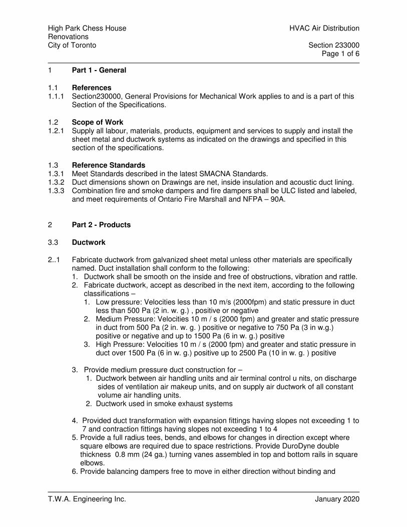
High Park Chess House HVAC Air Distribution Renovations City of Toronto Section 233000 Page 1 of 6
T.W.A. Engineering Inc. January 2020
1 Part 1 - General 1.1 References 1.1.1 Section230000, General Provisions for Mechanical Work applies to and is a part of this
Section of the Specifications. 1.2 Scope of Work 1.2.1 Supply all labour, materials, products, equipment and services to supply and install the
sheet metal and ductwork systems as indicated on the drawings and specified in this section of the specifications.
1.3 Reference Standards 1.3.1 Meet Standards described in the latest SMACNA Standards. 1.3.2 Duct dimensions shown on Drawings are net, inside insulation and acoustic duct lining. 1.3.3 Combination fire and smoke dampers and fire dampers shall be ULC listed and labeled,
and meet requirements of Ontario Fire Marshall and NFPA – 90A. 2 Part 2 - Products 3.3 Ductwork
2..1 Fabricate ductwork from galvanized sheet metal unless other materials are specifically
named. Duct installation shall conform to the following: 1. Ductwork shall be smooth on the inside and free of obstructions, vibration and rattle. 2. Fabricate ductwork, accept as described in the next item, according to the following
classifications – 1. Low pressure: Velocities less than 10 m/s (2000fpm) and static pressure in duct
less than 500 Pa (2 in. w. g.) , positive or negative 2. Medium Pressure: Velocities 10 m / s (2000 fpm) and greater and static pressure
in duct from 500 Pa (2 in. w. g. ) positive or negative to 750 Pa (3 in w.g.) positive or negative and up to 1500 Pa (6 in w. g.) positive
3. High Pressure: Velocities 10 m / s (2000 fpm) and greater and static pressure in duct over 1500 Pa (6 in w. g.) positive up to 2500 Pa (10 in w. g. ) positive
3. Provide medium pressure duct construction for –
1. Ductwork between air handling units and air terminal control u nits, on discharge sides of ventilation air makeup units, and on supply air ductwork of all constant volume air handling units.
2. Ductwork used in smoke exhaust systems
4. Provided duct transformation with expansion fittings having slopes not exceeding 1 to 7 and contraction fittings having slopes not exceeding 1 to 4 5. Provide a full radius tees, bends, and elbows for changes in direction except where square elbows are required due to space restrictions. Provide DuroDyne double thickness 0.8 mm (24 ga.) turning vanes assembled in top and bottom rails in square elbows. 6. Provide balancing dampers free to move in either direction without binding and

High Park Chess House HVAC Air Distribution Renovations City of Toronto Section 233000 Page 2 of 6
T.W.A. Engineering Inc. January 2020
rattling. Construct dampers in low and medium pressure ductwork from 1. 2 mm (18 gauge) galvanized sheet metal. Use manual quadrants on small ducts. On dampers longer than 375 mm (15 “) use push rods with DuroDyne Model SRP ball joints. Use two push rods on ducts wider than 600 mm (24”) 7. Isolate equipment with DuroDyne neoprene 0.* mm (0.32 “) thick flexible connectors with finished fabric width not less than 150 mm (6”) 8. Provide 50 mm (2 “) insulated sheet metal blank off panels behind unused portions of exterior louvers. 9. Seal all joints in low, medium and high pressure supply air ductwork with Transcontinential MP for low and medium pressure or DuroDyne S2 duct sealer for high pressure.
2..2 Construct round ductwork to meet high pressure duct standard and as follows –
1. Provide welded sleep joint construction round duct fittings. Wipe pipe and fittings with DuroDyne S2 duct sealer before assembly. Secure joints with self-tapping screws, then brush again with thick coat of duct sealer.
2. Provide dieformed round elbows through 200 mm (8”0 dia. Constructed from 1.1 Mm (20 gauge) galvanized steel. Provide 5 section construction for larger elbows.
3. Provide conical round tees. 2..3 Flexible ductwork–
1. Provide Flexmaster Triple Lock Aluminum, flexible ductwork upstream and
downstream of air terminal control units and / or other locations indicated on the Drawings.
2. Construct ductwork from a tape of soft annealed aluminum sheet, spiral would into a tube and spiral corrugated to provide strength and flexibility. Provide a triple mechanical lock to form a continuous secure air joint without the use of adhesives for pressures up to 3000 Pa (12”).
3. Conform to the requirements of NFPA 90 and Underwriters Laboratories classification for round duct to specifications 181.
2..4 Aluminum Ductwork –
1. Provide 3003 – H14 aluminum ductwork for the following systems – 1. Washroom exhaust
2. Construct aluminum ductwork in accordance with equivalent standards to the galvanized steel outlined in the SMACNA handbook.
3.3 Access Doors
2..1 Provide access doors for galvanized ductwork using 0.7 mm (24 gauge) galvanized
material with galvanized mounting frame and 25 mm (1”) rigid insulation between panels. Provide fastening devices to give tight closure.

High Park Chess House HVAC Air Distribution Renovations City of Toronto Section 233000 Page 3 of 6
T.W.A. Engineering Inc. January 2020
2..2 Provide access doors for stainless steel ductwork using 0.61 mm (24 gauge) stainless steel with stainless steel mounting frame and 25 mm (1 “) rigid insulation between panels. Provide fastening devices to give tight closure.
2..3 Provide access doors for aluminum ductwork of 0.61 mm (24 gauge) aluminum with rigid insulation between panels. Provide fastening devices to give tight closure.
2..4 Provide access doors and removable panels in plenums and casings of 1.31 mm (18 gauge) galvanized material with 50 mm (2 “) thickness fiberglass insulation. Equip doors with handles and hinges to open from either side (without risk of injury) as follows –
1. For mandoors –
1. Handles – Durodyne SP – 20 2. Hinges – Durodyne HB – 3 3. Gaskets – durodyne GN – 22
2. For removable panels –
1. Sash locks – Durodyne SL – 1 2. Gaskets – Durodyne GN – 22
2..5 Construct all access doors with double panels. 2..6 Provide neoprene gaskets securely formed into door frames around the periphery of all
ducts access doors. 2..7 Equip door frames for plenums and casings with hollow tubular gaskets. 3.3 Acoustic Duct Lining
2..1 Provide 25 Mm (1 “) thick fiberglass rigid coated duct liner, not less than 72.1 kg / cubic
metre (4.5 psf) density. Adhere liner with coated side towards the air stream, with 100% covering of Benjamin Foster 85-20 or Bakelite 230-38 adhesive, and mechanical fasteners at not greater than 400 mm (16 “) centres, on all four surfaces
3.3 Field Assembled Plenum and Casing Construction
2..1 Provide metal partitions, plenums and casings of not less than 1.61 mm (16 gauge)
galvanized sheet metal suitably reinforced with rolled angle sections. 2..2 Provide metal partitions, plenums and casings with adequate strength for all operating
conditions. Fabricate each sheet or material as a panel. Join panels by 40 mm (1.5 “) standing seams on outside of casings and secure with bolts at 300 mm (12 “) centres.
2..3 Provide closure baffles around banks of coils, filters and other inline components. 2..4 Provide 25 mm (1”) minimum size rolled structural steel angles where casing meets
floor. Caulk joints to prevent air and water leakage. 2..5 Flange and bolt casings on 150 mm (6”) centres to coils, blankoff panels and filler
panels. 2..6 Incorporate adjustable directional flow baffles into mixing plenums, to ensure complete
mixing of outdoor and return air streams with stratification not to exceed + - 2 C (+ - 4 F) across the coil face at winter outdoor design temperature.

High Park Chess House HVAC Air Distribution Renovations City of Toronto Section 233000 Page 4 of 6
T.W.A. Engineering Inc. January 2020
3.3 Fire Dampers 2..1 Provide Ruskin curtain or parallel blade type dampers to maintain fire rating integrity of
membrane being pierced. Minimum rating to be 1 – ½ hours with 100 C (212 F) fusible link. Provide multiple dampers where sizes exceed code limitation
2..2 Provide models as follows to suit application –
1. Normal duct application (2 hrs) - Model No. IBD – 2, Style B or C 2. Behind grilles (2 hrs.) - Model No. IBD – 2 3. In doors or thin separations (2 hrs) - Model # IBDT – 2 4. In fire walls (4 hrs) - Model # IBD – 23 5. Behind outlets in fire rated floor (roof) and ceiling assemblies (2 hrs) - Model # FSF 6. Combination fire and balancing damper (2 hrs) - Model # FD - 35
2..3 Select dampers with air flow resistance not exceeding 13 Pa (0.05 in. w. g.) at design
flow rates. 3.3 Grilles, Registers & Diffusers 2..1 Provide grilles, registers and diffusers from one manufacturer 2..2 Provide E.H. Price grilles, registers and diffusers for air quantities and locations shown
on Drawings. 2..3 Refer to drawing for description of types. 2..4 Equip each supply air terminal with a volume control damper and an equalizing grid. 2..5 Provide mitred corners and end borders for linear diffuser 2..6 Provide end cap for continuous linear diffuser terminating at walls and partitions.
3 Part 3 - Execution 3.1 Installation of Ductwork
3.1.1 All ductwork construction, support and installation shall be in accordance with
recommendations of the current ASHRAE Guide unless otherwise noted herein. 3.1.2 Ductwork, casings, plenums, etc. (unless otherwise noted) shall be constructed of first
quality, smooth finished, cold rolled galvanized steel guaranteed to double seam without fracturing. Ducts shall be formed with gauge marking on the exterior of the ductwork.
3.1.3 Sheet metal gauges and reinforcing shall be as follows except where otherwise noted: STEEL TRANSVERSE LONGEST SIDE U.S.GA. REINFORCING Up to 350mm wide 26 Flat S slip. 350mm to 457mm wide 24 Flat S slip. 483mm to 760mm wide 24 25mm (1") angle S slip. 1092mm - 1370mm wide 22 38mm (1½") angle S slip. 1400mm and over
Ducts shall have supplemental stiffening as required to prevent sagging or drumming and to provide a structurally sound assembly. Where the longest dimension of the duct is over 457mm (18") the duct shall have a cross broken panel on all four sides.
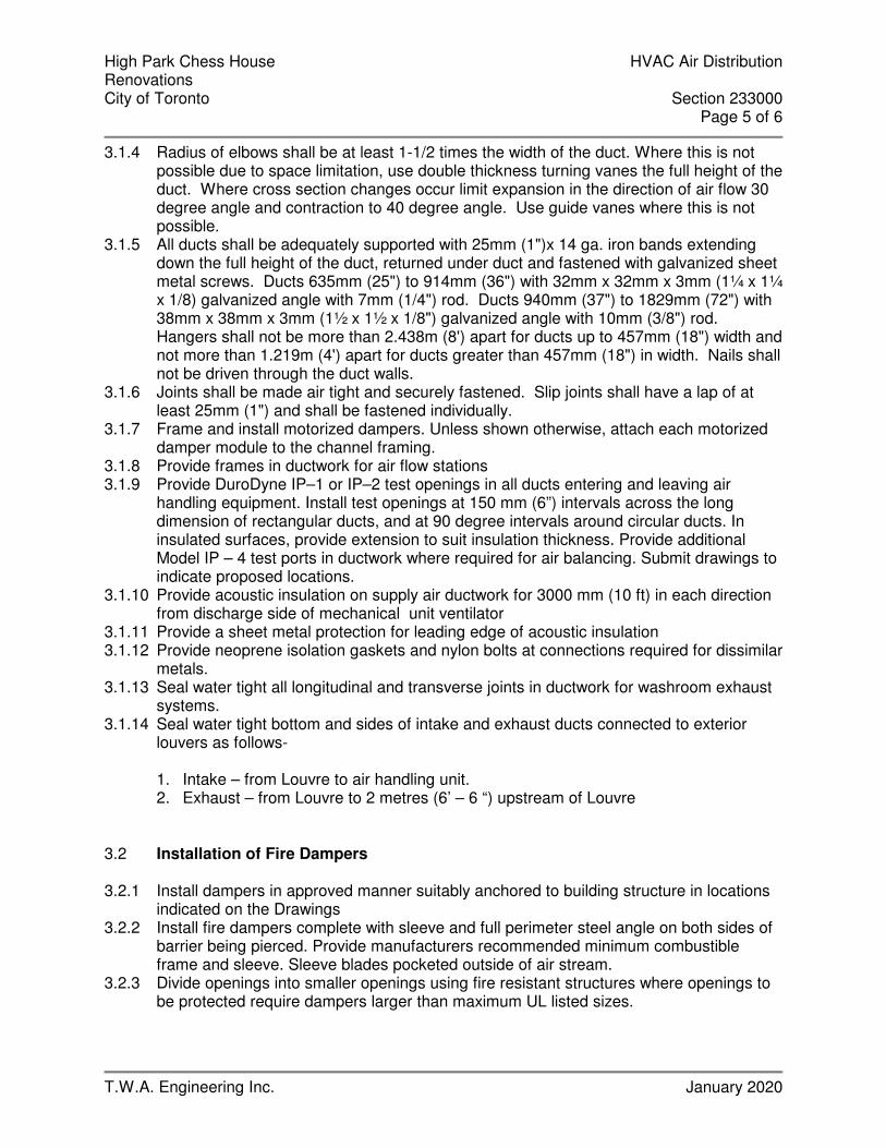
High Park Chess House HVAC Air Distribution Renovations City of Toronto Section 233000 Page 5 of 6
T.W.A. Engineering Inc. January 2020
3.1.4 Radius of elbows shall be at least 1-1/2 times the width of the duct. Where this is not possible due to space limitation, use double thickness turning vanes the full height of the duct. Where cross section changes occur limit expansion in the direction of air flow 30 degree angle and contraction to 40 degree angle. Use guide vanes where this is not possible.
3.1.5 All ducts shall be adequately supported with 25mm (1")x 14 ga. iron bands extending down the full height of the duct, returned under duct and fastened with galvanized sheet metal screws. Ducts 635mm (25") to 914mm (36") with 32mm x 32mm x 3mm (1¼ x 1¼ x 1/8) galvanized angle with 7mm (1/4") rod. Ducts 940mm (37") to 1829mm (72") with 38mm x 38mm x 3mm (1½ x 1½ x 1/8") galvanized angle with 10mm (3/8") rod. Hangers shall not be more than 2.438m (8') apart for ducts up to 457mm (18") width and not more than 1.219m (4') apart for ducts greater than 457mm (18") in width. Nails shall not be driven through the duct walls.
3.1.6 Joints shall be made air tight and securely fastened. Slip joints shall have a lap of at least 25mm (1") and shall be fastened individually.
3.1.7 Frame and install motorized dampers. Unless shown otherwise, attach each motorized damper module to the channel framing.
3.1.8 Provide frames in ductwork for air flow stations 3.1.9 Provide DuroDyne IP–1 or IP–2 test openings in all ducts entering and leaving air
handling equipment. Install test openings at 150 mm (6”) intervals across the long dimension of rectangular ducts, and at 90 degree intervals around circular ducts. In insulated surfaces, provide extension to suit insulation thickness. Provide additional Model IP – 4 test ports in ductwork where required for air balancing. Submit drawings to indicate proposed locations.
3.1.10 Provide acoustic insulation on supply air ductwork for 3000 mm (10 ft) in each direction from discharge side of mechanical unit ventilator
3.1.11 Provide a sheet metal protection for leading edge of acoustic insulation 3.1.12 Provide neoprene isolation gaskets and nylon bolts at connections required for dissimilar
metals. 3.1.13 Seal water tight all longitudinal and transverse joints in ductwork for washroom exhaust
systems. 3.1.14 Seal water tight bottom and sides of intake and exhaust ducts connected to exterior
louvers as follows-
1. Intake – from Louvre to air handling unit. 2. Exhaust – from Louvre to 2 metres (6’ – 6 “) upstream of Louvre
3.2 Installation of Fire Dampers 3.2.1 Install dampers in approved manner suitably anchored to building structure in locations
indicated on the Drawings 3.2.2 Install fire dampers complete with sleeve and full perimeter steel angle on both sides of
barrier being pierced. Provide manufacturers recommended minimum combustible frame and sleeve. Sleeve blades pocketed outside of air stream.
3.2.3 Divide openings into smaller openings using fire resistant structures where openings to be protected require dampers larger than maximum UL listed sizes.
High Park Chess House HVAC Air Distribution Renovations City of Toronto Section 233000 Page 6 of 6
T.W.A. Engineering Inc. January 2020
3.3 Installation of Grilles, Registers & Diffusers 3.3.1 Provide air terminals in strict accordance with manufacturer’s recommendations and
final reflected ceiling plans. 3.3.2 Provide plaster frames for units installed in plaster finishes. Fit frames tightly to prevent
leakage and smudging 3.4 Testing 3.4.1 Pressure test medium and high pressure ductwork to demonstrate leakage is 5% or less
of the sum of all connected outlets. 3.4.2 Test medium pressure duct at 1500 Pa (6in. w.g.) and high pressure duct at 2500 Pa
(10 in w.g.) static pressure. 3.4.3 Repair duct and retest where air leakage exceeds the specified limit. 3.4.4 Make good all audible leakage, whether test is within 5% limit or not 3.4.5 Provide calibrated tester, connection hoses, block ends, etc., as required 3.5 Clean Up 3.5.1 Vacuum clean the inside of all air handling systems, including fans, plenums, duts, coils
and terminal units to ensure that they are free from debris and dust.
- END OF SECTION 233000-

High Park Chess House Sheet Metal Insulation Renovations City of Toronto Section 234000 Page 1 of 3
T.W.A. Engineering Inc. January 2020
1 Part 1 - General 1.1 Work Included 1.1.1 Comply with Division 230000, General Requirements and all documents referred to
therein. 1.1.2 Provide all labour, materials, products, equipment and services to supply and install
thermal insulation, vapour barriers and finishes for mechanical work as indicated on the Drawings and specified in this Section of these Specifications.
1.2 Submittals 1.2.1 Submit samples and specification sheets of all types of insulation materials specified in
this Section of the Specifications. 2 Part 2 - Products 2.1 Materials – General 2.1.1 All insulation pertaining to Division 230000 shall be carried out by one firm specializing
in insulation work. 2.1.2 Acceptable insulation manufacturers are Knauf Insulation, Manson Insulation Inc and
Fiberglas Canada Inc. 2.1.3 Provide insulation and covers in strict accordance with authorities governing
combustibility and fireproofing of materials and in accordance with manufacturer’s recommendations.
2.1.4 Provide non-combustible insulation, jackets and finishes with ULC listed materials having a Flame Spread/Smoke Developed rating of 25/50 or less.
2.1.5 Attain a complete and continuous vapour barrier over insulation applied to cold and dual temperature piping, sheet metal and equipment. Use either factory applied vapour barrier jacket or field applied Reinforced Foil Flame Resistant Kraft vapour barrier jacket. Apply to piping, fittings, valves and inline components, sheet metal and fittings and equipment. Seal longitudinal and circumferential laps with Childers CP82 or Bakelite 230-39 adhesive. If vapour barrier jacket is not lapped, seal joints with self-adhering 100mm [4”] wide plain aluminum foil tape, or adhere 100 mm [4”] wide aluminum foil tape with Childers CP82 or Bakelite 230-39 adhesive. Jacketing with self-adhesive laps and self-adhesive vapour barrier tape will be an acceptable alternative closure system.
2.2 Sheet Metal Insulation 2.2.1 Prior to finishing of insulation of hot and cold exposed rectangular ductwork, provide
corner beads similar to Roll-on Type. 2.2.2 Apply vapour barrier over insulation on cold and dual temperature ducts. 2.2.3 Circular silencers and acoustic plenums need not be externally insulated. 2.2.4 Ductwork and casings linked with acoustic insulation 25 mm [1”] or more in thickness
need not be externally insulated. 2.2.5 Provide one of the following external sheet metal insulation types, and as scheduled in
the Sheet Metal Insulation Table. 2.2.5.1 Type D1: Fiberglas Rigid Duct Insulation, Knauf Rigid Insulation Board or Manson 800
Series Spin-Glas Rigid Insulation Board, not less than 48 kg/cubic metre [3 lbs./cu.ft.] density. Impale insulation on mechanically fastened pins located at not greater than 300 mm [12”] centres. Secure insulation with speed washers.
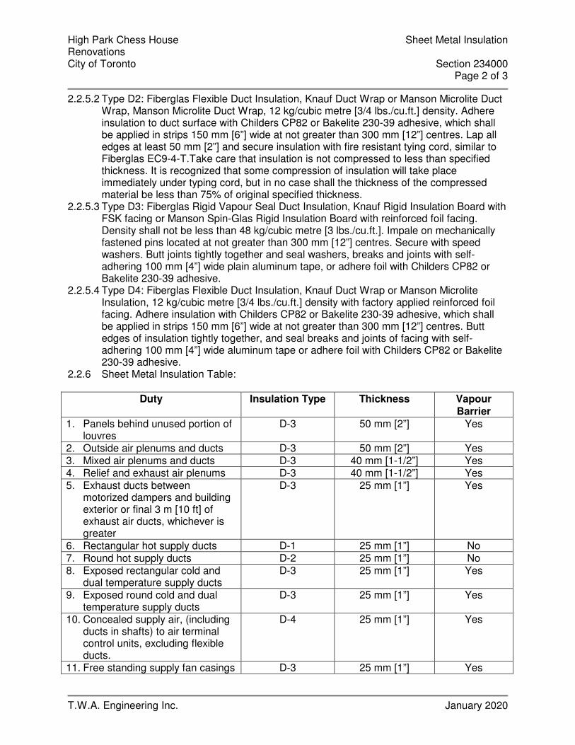
High Park Chess House Sheet Metal Insulation Renovations City of Toronto Section 234000 Page 2 of 3
T.W.A. Engineering Inc. January 2020
2.2.5.2 Type D2: Fiberglas Flexible Duct Insulation, Knauf Duct Wrap or Manson Microlite Duct Wrap, Manson Microlite Duct Wrap, 12 kg/cubic metre [3/4 lbs./cu.ft.] density. Adhere insulation to duct surface with Childers CP82 or Bakelite 230-39 adhesive, which shall be applied in strips 150 mm [6”] wide at not greater than 300 mm [12”] centres. Lap all edges at least 50 mm [2”] and secure insulation with fire resistant tying cord, similar to Fiberglas EC9-4-T.Take care that insulation is not compressed to less than specified thickness. It is recognized that some compression of insulation will take place immediately under typing cord, but in no case shall the thickness of the compressed material be less than 75% of original specified thickness.
2.2.5.3 Type D3: Fiberglas Rigid Vapour Seal Duct Insulation, Knauf Rigid Insulation Board with FSK facing or Manson Spin-Glas Rigid Insulation Board with reinforced foil facing. Density shall not be less than 48 kg/cubic metre [3 lbs./cu.ft.]. Impale on mechanically fastened pins located at not greater than 300 mm [12”] centres. Secure with speed washers. Butt joints tightly together and seal washers, breaks and joints with self-adhering 100 mm [4”] wide plain aluminum tape, or adhere foil with Childers CP82 or Bakelite 230-39 adhesive.
2.2.5.4 Type D4: Fiberglas Flexible Duct Insulation, Knauf Duct Wrap or Manson Microlite Insulation, 12 kg/cubic metre [3/4 lbs./cu.ft.] density with factory applied reinforced foil facing. Adhere insulation with Childers CP82 or Bakelite 230-39 adhesive, which shall be applied in strips 150 mm [6”] wide at not greater than 300 mm [12”] centres. Butt edges of insulation tightly together, and seal breaks and joints of facing with self-adhering 100 mm [4”] wide aluminum tape or adhere foil with Childers CP82 or Bakelite 230-39 adhesive.
2.2.6 Sheet Metal Insulation Table:
Duty Insulation Type Thickness Vapour Barrier
1. Panels behind unused portion of louvres
D-3 50 mm [2”] Yes
2. Outside air plenums and ducts D-3 50 mm [2”] Yes
3. Mixed air plenums and ducts D-3 40 mm [1-1/2”] Yes
4. Relief and exhaust air plenums D-3 40 mm [1-1/2”] Yes
5. Exhaust ducts between motorized dampers and building exterior or final 3 m [10 ft] of exhaust air ducts, whichever is greater
D-3 25 mm [1”] Yes
6. Rectangular hot supply ducts D-1 25 mm [1”] No 7. Round hot supply ducts D-2 25 mm [1”] No 8. Exposed rectangular cold and
dual temperature supply ducts D-3 25 mm [1”] Yes
9. Exposed round cold and dual temperature supply ducts
D-3 25 mm [1”] Yes
10. Concealed supply air, (including ducts in shafts) to air terminal control units, excluding flexible ducts.
D-4 25 mm [1”] Yes
11. Free standing supply fan casings D-3 25 mm [1”] Yes

High Park Chess House Sheet Metal Insulation Renovations City of Toronto Section 234000 Page 3 of 3
T.W.A. Engineering Inc. January 2020
12. Air conditioning unit casings D-3 25 mm [1”] Yes
13. Field fabricated casings D-3 40 mm [1-1/2”] Yes
- END OF SECTION 234000 -

High Park Chess House Fans Renovations City of Toronto Section 235010 Page 1 of 2
T.W.A. Engineering Inc. January 2020
1 Part 1 - General 1.1 References 1.1.1 Section230000, General Provisions for Mechanical Work applies to and is a part of this
Section of the Specifications. 1.2 Scope of Work 1.2.1 Supply all labour, materials, tools and equipment required to complete the installation
and testing in accordance with the full intent of the drawings and specifications. The work generally consists of, but is not limited to the following:
1.2.1.1 Exhaust Systems 1.2.1.2 Vibration Isolation 1.2.1.3 Counter Flashing 1.2.1.4 Complete Control System including Control Wiring 1.2.1.5 Balancing and Testing of System 1.2.1.6 Permits to Make Installation 1.2.2 NOTE: All equipment and accessories associated with this system and requirements
such as balancing, shall be as specified in all applicable sections of these specifications. 2 Part 2 - Products 2.1 Reference Standards 2.1.1 Fans to be standard products, selected from published literature of manufacturer. 2.1.2 Ratings to AMCA for sound and air delivery performance. Provide seal of approval on
each fan. 2.1.3 Fan shall be factory balanced, statically and dynamically to AMCA Standards 2.1.4 Factory finishe coat over primer on all parts. Sray paint before assembly and repaint
after. Field touchup all paint defects 2.2 Fans 2.2.1 Supply and install, where shown on the drawings, quiet operating fans and motors of
types and size, rotation and discharge arrangements, motor locations, motor H.P., capacity in CFM, static pressure, etc. as shown.
2.2.2 Fan motors provided shall have H.P. rating sufficient to handle full air quantity shown at a total static pressure 33% in excess of design static pressure shown on the drawings.
2.2.3 Individual exhaust fans shall be equal to ZONEX, BROAN or REVERSOMATIC, as per the schedules on the drawings.
3 Part 3 - Execution 3.1 References 3.1.1 Refer to Section 230010 for Execution Requirements which apply to Ventilation work
but which also apply to other Sections of this Division of the Specification. 3.1.2 This Trade Contractor shall be responsible for all co-ordination with other trades
affecting the ductwork lay out. Detailed interference drawings are to be produced by this trade. No "extras" are allowed for changes or re-routing in ductwork due to interference co-ordination.

High Park Chess House Fans Renovations City of Toronto Section 235010 Page 2 of 2
T.W.A. Engineering Inc. January 2020
3.1.3 Provide fire dampers in all ducts over 129 sq. cm.(20 sq.in.) in area in all ducts
penetrating through fire walls, whether or not specifically requested by ordinances and codes.
3.2 Installation of Fans 3.2.1 Supply and install fans as specified on the drawings. All fans are subject to the
Engineer's approval prior to ordering and installation. 3.2.2 All fans located outside of the building (on the roof etc.) shall be weatherproof and shall
include a weatherproof disconnect switch at the fan location. 3.2.3 Neoprene vibration pads shall be installed under each fan. The installation shall be in
accordance with the recommendations of the vibration pad manufacturer. 3.3 Installation of Electrical Wiring 3.3.1 All electrical wiring other than control wiring shall be done by Division 16 unless
otherwise noted. Ventilation sub-contractor shall supply the starters for fans. All motors up to and including ½ HP shall be 1 phase, 60 hz, 115 volts; 3/4 HP and over shall be 3 phase. Voltage and characteristics shall be con-firmed with electrical drawings before ordering equipment.
3.3.2 All motor starters shall be provided with over load protection in all phases. 3.3.3 The ventilation sub-contractor shall supply, with each piece of equipment, a suitable
disconnect switch. Where equipment is located outdoors, the switch shall be waterproofed. On package equipment, disconnect switch shall be installed and completely wired on the load side only.
3.3.4 All motor starters shall be magnetic, in a CEMA I enclosure and provided with over load protection in all phases, fused control transformer running pilot light, H.O.A., selector switch and 1-NO and 1-NC extra dry contract.
3.4 Air Balancing and Setting of Dampers 3.4.1 All heating and ventilation systems shall be balanced to obtain the airflow conditions
specified and given on the drawings. After the balancing has been completed, an air balance report shall be prepared, indicating all air flows and the fan performances, which shall include fan RPM, fan static and total pressure and fan amperage draw. Three (3) copies to be submitted to the Engineer.
- END OF SECTION 235010 -

SPECIFICATIONS
FOR
HIGH PARK CHESS HOUSE
PHASE 1 RENOVATIONS 1879 BLOOR STREET WEST
TORONTO, ONTARIO
Project number: 1907
PREPARED BY
Solid Ground Engineering 59 Rosslyn Avenue North
Hamilton ON L8L 7P3
Tel: (416) 807-6054
E-MAIL: [email protected]
Issued: January 23, 2020 (For Tender)

High Park Chess House Division 26 Specification Phase 1 Renovations Table of Contents City of Toronto Page 1 of 1
Solid Ground Engineering January 2020
TABLE OF CONTENTS
DIVISION 26 - ELECTRICAL SECTION DESCRIPTION PAGES 26 01 00 Electrical General Requirements 8 26 05 19 Wire and Cable 2
26 05 26 Grounding 2 26 05 29 Fastenings and Supports 1 26 05 33.13 Conduits, Fastenings and Fittings 1 26 05 33.16 Outlet Boxes 2 26 05 83 Wiring Connectors 1 26 24 16 Panelboards 1 26 27 26 Wiring Devices 1 26 28 13 Fuses 1 26 28 16 Disconnect Switches 1 26 50 00 Light Fixtures 1 26 52 00 Emergency Battery Lighting 1 26 53 00 Exit Lights 1 26 70 00 Electric Heating 1
High Park Chess House Electrical General Requirements Phase 1 Renovations Section 26 01 00 City of Toronto Page 1 of 8
Solid Ground Engineering January 2020
1 General 1.1 This Section covers items common to Sections of Division 26. This section supplements
the general requirements the City of Toronto. 1.2 Performance of the work under this contract shall be scheduled and coordinated with the
General Contractor and Project Manager. For pricing purposes, the bidder shall assume that the work will be executed during normal working hours. Allow for over-time pay when preparing bid.
1.3 The exact scheduling and work procedure shall be determined at the time of execution of the work.
1.4 The electrical contractor shall provide a total turnkey service and shall be accountable for all the work as stipulated on the drawings and these specifications.
1.5 The contractor shall list the names of any sub-contractors that shall be used in the bid.
2 Codes and Standards 2.1 Do complete installation in accordance with the Ontario Electrical Safety Code, CSA
C22.1-18, 27th edition except where specified otherwise. 2.2 Do overhead systems in accordance with the latest edition of CSA C22.3No.1-
M87(R1997) except where specified otherwise. 2.3 Abbreviations for electrical terms: to the latest edition of CSA Z85-1983. 3 Care, Operation and Start-Up 3.1 Instruct operating personnel in the operation, care and maintenance of equipment. 3.2 Provide these services for such period, and for as many visits as necessary to put
equipment in operation, and ensure that operating personnel are conversant with all aspects of its care and operation.
4 Voltage Ratings 4.1 Operating voltages: to the latest CAN3-C235. 5 Permits, Fees and Inspection 5.1 Apply for, obtain and pay for all permits, licenses, inspections, examinations and fees
required, for the Work pertaining to this Division. 5.2 For any electrical work required within the jurisdiction of the Ontario Electrical Safety
Code, the electrical contractor shall provide drawings and specifications required by the Electrical Safety Authority and obtain a permit as required. Pay any associated fees for permit application and inspection by the E.S.A.
5.3 Furnish Certificates of Acceptance from Electrical Safety Authority on completion of work to Engineer. Provide a copy in each maintenance manual.
6 Materials and Equipment 6.1 All equipment and material to be CSA certified. 6.2 Lifting platforms, scissor lifts, extension ladders etc. required to execute the work under
this contract are to be provided by the electrical contractor. 7 Finishes 7.1 Clean and touch up surfaces of shop-painted equipment scratched or marred during
shipment or installation, to match original paint. 7.2 Clean and prime exposed non-galvanized hangers, racks and fastenings with white
enamel paint to prevent rusting.
High Park Chess House Electrical General Requirements Phase 1 Renovations Section 26 01 00 City of Toronto Page 2 of 8
Solid Ground Engineering January 2020
7.3 Paint all surface mounted conduits installed under this contract with white enamel paint. 8 Equipment Identification 8.1 All electrical equipment shall be identified with lamacoid plastic plates, blue background
with white etched letters. 8.2 Identify new circuits on existing panel board directories. 9 Wiring Identification 9.1 Identify wiring and cabling with permanent indelible identifying markings, either
numbered or coloured plastic tapes, on both ends of phase conductors of feeders, branch circuit wiring, data and voice communication cabling.
10 Wiring Terminations 10.1 Lugs, terminals, screws used for termination of wiring to be suitable for either copper or
aluminum conductors. 11 Manufacturers and CSA Labels 11.1 Visible and legible after equipment is installed.
12 Temporary Power
12.1 Provide under this Contract a temporary service on job site for use by construction facilities. Exact location to be determined on site.
12.2 Exact description of services required must be negotiated with General Contractor and/or Owner.
12.3 'Used' wiring and equipment may be utilized for temporary wiring. All temporary wiring and equipment shall remain the property of the Electrical Contractor and shall be removed from the site at the time directed by the General Contractor.
13 Submittals
13.1 Submit shop drawings, prepare record drawings and provide maintenance and operating instructions in accordance with the requirements of the City of Toronto.
14 Mounting Heights 14.1 Mounting height of equipment is from finished floor to center line of equipment unless
specified or indicated otherwise. 14.2 If mounting height of equipment is not specified or indicated, verify before proceeding
with installation.
15 Demolition and Removal
15.1 All removed conduit, wiring, fixtures, boxes etc. shall be disposed and removed from the site by the Contractor.
15.2 Remove and turn over all removed devices and fixtures to the City. 15.3 Remove old cabling where practical and dispose to scrap. 15.4 Provide blank white cover plates on all unused outlet boxes that have been vacated.
16 Site Visit
16.1 The Contractor shall visit the facility in accordance with the City of Toronto’s general requirements.
High Park Chess House Electrical General Requirements Phase 1 Renovations Section 26 01 00 City of Toronto Page 3 of 8
Solid Ground Engineering January 2020
16.2 The Contractor shall make absolutely sure of the existing conditions and location of existing electrical equipment prior to submitting a bid.
17 Cutting and Patching 17.1 In existing work and work already finished as part of this Division, cutting and patching
will be carried out by the electrical contractor at the expense of this Division. Obtain the approval of the consultant before doing any cutting. Supporting members of any floor, wall or the building structure shall be cut only in a manner approved by the consultant. Provide all patching as required. This work shall be performed in accordance with the requirements of the corresponding Division of the specifications.
17.2 Prior to core drilling any floor slabs, the contractor shall scan and/or x-ray the slab to ensure that there are no existing buried electrical conductors or any elements that would affect the structural integrity.
18 Access Doors 18.1 Access doors shall be sized and located to suit the applied wall and ceiling materials.
Use ULC labeled access doors that act as fire barriers. 19 Clean Up 19.1 Clean up daily and remove all debris from site. 20 Contract Drawings 20.1 The contract drawings for the electrical work are performance drawings, diagrammatic
intended to convey the scope of work and indicate general arrangement and approximate location of equipment, raceways etc. The drawings do not intend to reflect architectural and structural details.
20.2 Do not scale drawings but obtain information involving accurate dimensions shown on drawings and by site measurements.
20.3 Make at no additional cost, any changes or additions to material and equipment necessary to accommodate structural conditions (runs around beams, columns etc.).
20.4 Alter at no additional cost the location of materials and/or equipment as directed provided that the changes are made before installation and do not necessitate additional material.
20.5 (Reserved). 20.6 Leave space clear and install work to accommodate future materials and/or material
supplied by other trades. Verify spaces in which work will be installed. Install conduit, cable and bus duct runs to maintain headroom and clearances to conserve space in shafts and ceiling spaces.
20.7 Confirm on site the exact location of outlets and fixtures. Confirm location of outlets for equipment supplied by others.
21. Shop Drawings 21.1 Submit shop drawings and product data in accordance with the City of Toronto General
Requirements. 21.2 Process shop drawings to suit the manufacturing schedule and construction schedule.
Do not manufacture any equipment until final review of shop drawings has been completed.
21.3 Submit shop drawings to the authorities having submission, as required. 21.4 Provide shop drawings for the following: 21.4.1 Lighting Fixtures.

High Park Chess House Electrical General Requirements Phase 1 Renovations Section 26 01 00 City of Toronto Page 4 of 8
Solid Ground Engineering January 2020
21.4.2 Occupancy Sensors. 21.4.3 Emergency Battery Lighting. 21.4.4 Exit Lights. 21.4.5 Electric Heating. 21.4.6 Panelboards. 21.4.7 Electric Heating Thermostats. 21.4.8 Hand Dryers. 21.4.9 Control Transformers, Relays. 21.4.10 Time Switches. 21.4.11 Photocontrols. 21.4.12 (Reserved). 21.5 Bind one set of all shop drawings in each operation and maintenance manual. 22 Reserved 23 Operation and Maintenance Manuals 23.1 Submit Operation and Maintenance manuals in accordance with City of Toronto General
Requirements. 23.2 Assemble three (3) manuals each containing all approved shop drawings, operating and
maintenance instructions for all equipment provided under the contract. Present copies for review and provide the Project Manager the reviewed copies. Manuals shall be in a three-ring hard-covered binder.
23.3 Manuals shall include but not be limited to the following information and documentation: 23.3.1 All approved shop drawings. 23.3.2 ESA certificate. 23.3.3 Warranties. 23.3.4 “As-built” drawings. 24 Completion of Contract 24.1 Systems shall be complete, tested and ready for use with all equipment operating
satisfactorily. 24.2 Any circuit breakers for new circuits provided under the contract shall be clearly
identified at panels. 24.3 Provide certificates of guarantee of workmanship, materials and equipment for one year
after the date of substantial completion. Repair and or replace without charge to the City all defects due to imperfect materials or workmanship that appear within one year of acceptance of work.
25 Workmanship and Supervision 25.1 Workmanship and installation methods shall conform to the best standard practice. Work
shall be performed by skilled tradesmen under the supervision of fully qualified personnel.
25.2 Install equipment in strict accordance with manufacturer’s written recommendations. 25.3 When requested, submit samples of materials proposed for review before proceeding
with the work. 25.4 Conceal conduit in finished areas and where practical. Where exposed conduit is used,
run straight and perpendicular with building lines. 25.5 Install equipment and materials to present a neat appearance. Ensure that horizontal
raceway is level and that equipment is plumb.

High Park Chess House Electrical General Requirements Phase 1 Renovations Section 26 01 00 City of Toronto Page 5 of 8
Solid Ground Engineering January 2020
25.6 Maintain on the jobsite, at all times, qualified superintendents and foremen with proven experience in supervising, testing and adjusting projects of a similar nature and complexity.
26 Asbestos 26.1 If, during the course of work, materials suspected of containing asbestos are
encountered, the following procedure shall be followed: 26.1.1 Cease work immediately that may disturb the suspect material. Do not clean up, cover,
move or contact suspect material. 26.1.2 Isolate the immediate work area by locking doors, installing barricades etc. 26.1.3 Notify the General Contractor and Project Manager in charge of the project of the
situation. 27 Noise and Vibration 27.1 Electrical equipment shall operate without objectionable noise or vibration. 27.2 If such objectionable noise or vibration should be produced and transmitted to occupied
portions of the building by apparatus, ducts, conduits, ballasts or other parts of the electrical work, make the necessary changes and/or additions, as approved, without extra cost to the Owner.
27.3 Connections to rotating, vibrating, magnetic or other noise producing equipment such as motors, transformers, contactors, etc. shall be by way of looped flexible conduits.
28 Vouchers 28.1 When called upon to do so by the Owner, provide vouchers to show that the work and
materials are being paid for as the work progresses, and to substantiate the value of the work complete to that date.
29 Valuation of Changes 29.1 Refer to and conform with the requirements set out in the Instructions to Bidders. 29.2 Submissions will be scrutinized by the consultant and, therefore, require complete
breakdown of all material, labour units and mark-ups. 29.3 In the event of any extra or additional work of any nature being required during the
progress of the work, this Trade Contractor is hereby warned that in order to secure settlement for such extras, he has to obtain the Owner's, General Contractor's and the consultant's approval prior to starting the extra work and shall definitely state in writing the cost of such extras and credits at the time he is requested to do the work.
29.4 Unless the extras are approved they will not be allowed. 30 Excavation and Backfill 30.1 Excavate and backfilling and concrete work as required for all electrical work shall be
carried out by the Electrical Contractor. 31 Expediting 31.1 Continuously check and expedite delivery of all pretendered equipment; equipment to be
supplied under this contract and all materials required for the successful execution of this contract.
31.2 If necessary, inspect at the source of manufacture to confirm status. 31.3 Continuously check and ensure that the necessary information is communicated to all
parties involved.

High Park Chess House Electrical General Requirements Phase 1 Renovations Section 26 01 00 City of Toronto Page 6 of 8
Solid Ground Engineering January 2020
31.4 Immediately inform the Project Manager and/or Owner of any anticipated delays in writing, confirming date of order and release for shipment of materials or equipment delayed.
32 (Reserved) 33 Painting 33.1 Supply exposed ferrous metal work, except conduits, with at least one factory prime
coat, or paint one prime coat on the job. Clean up or wire brush equipment, conduit, etc., before painting. Finish painting will be done under painting and finishing division 9 unless specifically noted otherwise.
33.2 Clean up and wire brush concealed ferrous supports and hangers, in ceiling space and shafts, and supply two coats of zinc chromeate (C.G.S.B. 1-GP-140B)
34 Plywood 34.1 All plywood backboards will be supplied and installed by the Electrical Contractor. These
backboards will be primed and painted grey on one side by the Electrical Contractor. 35 Sleeves, Sealing and Fireproofing 35.1 Through all interior walls, use standard weight steel pipe, machine cut, flush with the
finished structure. Coordinate with room finish schedule. 35.2 Through all exterior walls above grade, use standard weight steel pipe, machine cut,
flush with finished structure inside and to suit flushing on the outside. 35.3 Through all waterproof floor, through janitors closets, boiler rooms, mechanical rooms,
kitchens, and roofs, use genuine wrought iron or extra heavy cast iron sleeves, machine cut. Extend sleeves a minimum of 50mm. above finished floor and cut flush with underside of floor.
35.4 Pack all sleeves with ThermaFibre Fire Stop material manufactured by Canadian Gypsum Co. and to Architect's approval.
36 Trial Use 36.1 The trial or temporary use of the system or any part thereof by the owner shall not be
construed as evidence of acceptance. The owner shall have the privilege of testing and learning the operational procedure for such length of time as deemed reasonable by the architect. These operations shall be carried out only after due notice has been given and no responsibility shall be waived because of this operation.
37 Tests 37.1 A review of the work shall be carried out after completion of the work. Furnish required
personnel to assist the consultant witnessing the test specified. Advise the consultant when the equipment is ready for testing and then set a date for tests.
37.2 If the results of these tests do not meet the requirements of the specification, make the appropriate corrections and provide, as set out above, for further similar test.
38 “As-Built” Drawings 38.1 The Contractor shall obtain from the Owner a complete and separate set of white prints (drawings) and specifications to keep on the site at all times. 38.2 These prints shall be marked up by the Contractor to record clearly, neatly, accurately and promptly and all locations of electrical work and deviations from and changes to the contract documents.

High Park Chess House Electrical General Requirements Phase 1 Renovations Section 26 01 00 City of Toronto Page 7 of 8
Solid Ground Engineering January 2020
38.3 All changes from the contract documents shall be marked in red ink. 38.4 The accurate location, size and type of each service line shall be recorded before concealment to ensure accurate and direct future access to these buried lines. 38.5 The as-built drawings will be reviewed by the Consultant and will be taken into consideration when reviewing the applications for progress payment. 38.6 Incorporate all changes made to the drawings through Change Orders, Change Directives, Supplemental Instructions, Site Conditions etc. 38.7 Prepare specification as-builts. Record as-built products including manufacturer and model numbers. 38.8 Before applying for a Certificate of Substantial Performance of Work, obtain the electronic files from the Engineer, pay any electronic files fee and sign the copyright waiver. 38.9 The electronic files are non-transferrable and shall be used solely by the contractor that paid the fee and signed the copyright waiver. 38.10 As-Built Documentation 38.10.1 Upon satisfactory review, submit two (2) copies of as-built documents. 38.10.2 Submit as-built pdf and AutoCAD files of as-built documents. 38.10.3 A list of AutoCAD and pdf files required at closeout are to be compiled in a master. CAD drawings and pdf drawings are to be on separate spread sheets. 38.10.4 Excel sheet database heading: 38.10.4.1 Location – Project location information from title block. 38.10.4.2 Component – Property or structure use. 38.10.4.3 Year – Year the drawing was completed as indicated on title block. 38.10.4.4 Drawing # - Drawing number as indicated on title block. 38.10.4.5 Description – Purpose of the drawing as indicated in title block. 38.10.4.6 Type – Drawing status. 38.10.4.7 File Name – City file naming standard. 38.10.5 PDF and AutoCAD Drawing Names as follows: 38.10.5.1 Facility Name. 38.10.5.2 Year. 38.10.5.3 Drawing Number. 38.10.5.4 Pdf or Dwg. 38.10.6 When submitting as-built drawings, submit the following together in one package: 38.10.6.1 Colour scan in pdf format of site marked-up drawings on compact disc. 38.10.6.2 As-built drawings in both CAD and pdf formats on compact disc. CAD file and pdfs shall be prepared with font, line weights etc. conforming to the consultant’s drawing standard. 38.11 An incomplete submission will be considered as not received and will not be reviewed. 38.12 The electrical contractor acknowledges that the Owner or Consultant shall withhold funds from his contract not exceeding the cost of producing "As Built" drawings by a third party if the above is not strictly adhered to. 39 Workplace Safety 39.1 Perform all work in accordance with CSA Standard Z462-15, “Workplace Electrical Safety” and the Ontario Electrical Safety Code, 25th edition.

High Park Chess House Electrical General Requirements Phase 1 Renovations Section 26 01 00 City of Toronto Page 8 of 8
Solid Ground Engineering January 2020
40 Cash Allowances 40.1 Cash allowances shall be included in the base bid contract. Should any draws against
cash allowances not be required, the amounts of the cash allowances shall be deducted from the contract value.
40.2 Draws against cash allowances shall not be subject to additional charges for overhead and profit in accordance with City of Toronto policies.
40.3 Any and all cash allowances pertaining to electrical work shall be carried by the electrical contractor.
40.4 Any draws against the cash allowances shall be backed up with invoices from the respective third parties, sub-contractors, suppliers etc.
40.5 All cash allowances pertaining to electrical work shall be included in the tender price schedule front end documents.
40.6 (Reserved). 41 Separate Prices 41.1 Provide separate prices for work described below. Separate prices shall not be included in the base contract. Should any of the work for which a separate price has been requested proceed, the contractor will be given an instruction to proceed accordingly and will be paid an extra amount equal to the separate price stipulated. 41.2 It will be established either at the onset or during the progress of construction whether any work for which a separate price has been assigned is to be included in the scope of work. Confirm with the Consultant and/or Project Supervisor whether the work is to proceed. 41.3 (Reserved).
- END OF SECTION 26 01 00 -

High Park Chess House Wire and Cable Phase 1 Renovations Section 26 05 19 City of Toronto Page 1 of 2
Solid Ground Engineering January 2020
1 PART 1 - GENERAL 1.1 Product Data 1.1.1 Conform to the General Requirements in Section 26 01 00. 1.2 Scope 1.2.1 Electrical contractor shall provide all power wiring in conduit unless noted otherwise. 2 PART 2 - PRODUCTS 2.1 Materials 2.1.1 Normal Distribution Voltage Wiring (600V & Lower): 2.1.1.1 All feeders shall be RW-90 cross-linked polyethylene copper conductors in EMT conduit
unless otherwise noted on drawings. 2.1.1.2 Main secondary (underground) feeders shall be RWU-90 cross-linked polyethylene
copper conductors in concrete-encased ductbank. 2.1.1.1 Armoured cables: Corflex or Teck are allowed to be used where stated on the drawings. 2.1.1.2 All branch circuits shall be RW90 or T90 copper, minimum #12AWG. All shall be
installed in EMT conduit. 2.1.1.3 BX or armoured cable size #14 and #12AWG copper for concealed wiring. 2.1.2 Control Wiring: 2.1.2.1 Thermostats or other low voltage devices shall be wired with #18 LVT in plastic jacket. 2.1.2.2 120V control circuits use #14 TWH or R90 in EMT conduit. 2.1.3 Heavy Duty Service Cords 2.1.3.1 Type SOW. 2.1.3.1.1 Outdoor cords rated at 90ºC to -34ºC (CSA rating), for use in wet or dry locations. 2.1.3.1.2 Copper conductors with rubber insulation, twisted with fillers and an oil resistant,
flame retardant jacket, FT1 rated. 2.1.3.1.3 Conductors colour coded black, white, green, red. 2.1.3.1.4 To CSA C22.2 No. 49-M. 3 PART 3 - EXECUTION 3.1 Installation 3.2 Armoured Cables: 3.3 Do not directly bury armoured cables in or below concrete slabs or walls. 3.4 Where several armoured cables are routed together they shall be supported on trays or
conduits, ladders, channels or inserts. 3.5 Single armoured cables of a 3 or 4 wire circuit shall be run with uniform spacing not less
than one cable diameter throughout the feeder length for free air rating. 3.6 Use isolation type cable clamps to ensure proper and uniform cable spacing. 3.7 Where cables are installed on walls, provide mechanical protection over them up to 2400
mm above finished floor, using a 12 gauge U-section steel cover.

High Park Chess House Wire and Cable Phase 1 Renovations Section 26 05 19 City of Toronto Page 2 of 2
Solid Ground Engineering January 2020
3.8 Cable connections to all enclosures, boxes and panels shall be by means of a water tight malleable aluminum connector.
3.9 Megger all cables after installation and before energization. 3.10 Caution - Do not encircle single conductor cable with ferrous metal. 3.11 Low Voltage Armoured Cables (BX): 3.12 These cables must be run concealed and be used only for the following purposes: 3.13 Final connection from a ceiling outlet box to a lighting fixture. 3.14 Final connection from a ceiling outlet box to a utility pole. 3.15 Drop from a ceiling outlet box to a partition outlet. 3.16 Use throat connectors and anti-short sleeves at all dressed ends. 3.17 2/C #12 AWG plus ground may be used for final connection to suspended fixtures. 3.18 Wiring in Conduit: 3.19 Minimum wire size shall be as previously mentioned, unless otherwise stated. 3.20 Maximum voltage drop between the furthest outlet of a fully loaded circuit and the panel
to which it is connected shall not exceed 2%. 3.21 Provide pigtails at all outlets for fixtures and wiring devices. All neutrals and branch
circuits shall be connected in each outlet box to avoid a break in the neutral or circuit wire when fixture or wiring device is disconnected.
3.22 Feeder cable connections shall be made with solderless type lugs having sufficient contact areas and large enough screw to apply proper pressure for the feeder cables used.
3.23 All wiring shall be identified.
- END OF SECTION 26 05 19 –
High Park Chess House Grounding Phase 1 Renovations Section 26 05 26 City of Toronto Page 1 of 2
Solid Ground Engineering January 2020
1 PART 1 - GENERAL 1.1 Scope 1.1.1 Provide grounding of all new electrical equipment installed under the scope of work. 1.2 Standards 1.2.1 Provide all system grounding and bonding in accordance with the requirements of the
2018 Ontario Electrical Safety Code and IEEE report #953 (Grounding of Industrial Power).
2 PART 2 - PRODUCTS 2.1 Equipment 2.1.1 Clamps for grounding of conductor, size as required to electrically conductive
underground water pipe. 2.1.2 Copper conductor minimum 6 m long for each concrete encased electrode, bare,
stranded, soft annealed. 2.1.3 Rod electrodes, copper clad steel 19 mm diameter by 3 m long. 2.1.4 System and circuit, equipment, grounding conductors, bare stranded copper, soft
annealed. 2.1.5 Insulated grounding conductors: green, type RW90. 2.1.6 Ground bus: copper complete with insulated supports, fastenings, connectors. 2.1.7 Non-corroding accessories necessary for grounding system, type, size, material as indicated, including but not necessarily limited to: 2.1.7.1 Grounding and bonding bushings. 2.1.7.2 Protective type clamps. 2.1.7.3 Bolted type conductor connectors. 2.1.7.4 Thermite welded type conductor connectors. 2.1.7.5 Bonding jumpers, straps. 2.1.7.6 Pressure wire connectors. 3 PART 3 - EXECUTION 3.1 Installation - General 3.1.1 Install complete permanent, continuous, system and circuit, equipment, grounding
systems including, electrodes (if required), conductors, connectors, accessories, as indicated, to conform to requirements of Electrical Safety Authority over installation. Where EMT is used, run ground wire in conduit.
3.1.2 Install connectors in accordance with manufacturer's instructions. 3.1.3 Protect exposed grounding conductors from mechanical injury. 3.1.4 Make buried connections, and connections to substation electrodes and ground bus,
using copper welding by thermite process. 3.1.5 Use mechanical connectors for grounding connections to equipment provided with lugs
and to existing ground bus. 3.1.6 Soldered joints not permitted. 3.1.7 Install bonding wire for flexible conduit, connected at both ends to grounding bushing,
solderless lug, clamp or cup washer and screw. Neatly cleat bonding wire to exterior of flexible conduit.
High Park Chess House Grounding Phase 1 Renovations Section 26 05 26 City of Toronto Page 2 of 2
Solid Ground Engineering January 2020
3.1.8 Install flexible ground straps for bus duct enclosure joints, where such bonding is not inherently provided with equipment.
3.1.9 Provide bonding of new metallic gas service piping inside building to the electrical service ground in accordance with the OESC and applicable bulletins. Install clamp on metal gas piping (downstream of gas meter) and provide a #6 AWG copper conductor from clamp to building service ground.
3.2 Equipment Grounding 3.2.1 Install grounding connections to typical equipment included in, but not necessarily
limited to service equipment, transformers, switchgear, duct systems, building steel work.
3.3 Field Quality Control 3.3.1 Perform tests in accordance with Section 26 01 00 – Electrical General Requirements. 3.3.2 Perform ground continuity and resistance tests using method appropriate to site
conditions and to approval of local authority having jurisdiction over installation. 3.3.3 Perform tests before energizing electrical system. 3.3.4 Disconnect ground fault indicator during tests.
- END OF SECTION 26 05 26 -

High Park Chess House Fastenings and Supports Phase 1 Renovations Section 26 05 29 City of Toronto Page 1 of 1
Solid Ground Engineering January 2020
1 PART 1 - GENERAL 1.1 Conform to the General Requirements of Section 26 01 00. 2 PART 2 - PRODUCTS 2.1 Materials 2.1.1 Expandable inserts to secure equipment to hollow masonry. 2.1.2 Twist clip fasteners to secure surface mounted equipment to inverted T-bar ceilings.
Ensure that the T-bars are adequately supported to carry weight of equipment specified before installation of same.
2.1.3 Support channel, length as required, U-shaped, No. 12 gauge Unistrut, Series P-1000 for surface or suspended applications.
3 PART 3 - EXECUTION 3.1 Installation 3.1.1 Secure equipment to masonry, tile and plaster surfaces with lead anchors or nylon
shields. 3.1.2 Secure equipment to poured concrete with expandable inserts. 3.1.3 Secure equipment to hollow masonry walls or suspended ceilings with toggle bolts. 3.1.4 Support equipment, conduit or cables using clips, spring loaded bolts, cable clamps
designed as accessories to basic channel members. 3.1.5 Fasten exposed conduit or cables to building construction or support system using
straps. 3.1.5.1 One-hole steel straps to secure surface conduits and cables 50 mm and smaller. 3.1.5.2 Two-hole steel straps for conduits and cables larger than 50 mm. 3.1.5.3 Beam clamps to secure conduit to exposed steel work. 3.1.6 Suspended support systems. 3.1.6.1 Support individual cable or conduit runs with 13 mm diameter threaded rods and spring
clips. 3.1.7 For surface mounting of two or more conduits use channels at 1.5 m oc spacing. 3.1.8 Provide metal brackets, frames, hangers, clamps and related types of support structures
where indicated or as required to support conduit and cable runs. 3.1.9 Do not use wire lashing or perforated strap to support or secure raceways or cables. 3.1.10 Do not use supports or equipment installed other trades for conduit or cable support
except with permission of other trade. 3.1.11 Provide adequate support for raceways and cables dropped vertically to equipment
where there is no wall support. 3.1.12 Install fastenings and supports as required for each type of equipment cables and
conduits, and in accordance with manufacturer’s installation recommendations.
- END OF SECTION 26 05 29 -

High Park Chess House Conduits, Fastenings and Fittings Phase 1 Renovations Section 26 05 33.13 City of Toronto Page 1 of 1
Solid Ground Engineering January 2020
1 PART 1 - GENERAL 1.1 Location of Conduit 1.1.1 Drawings do not indicate all conduit runs. Those indicated are in diagrammatic form
only. 2 PART 2 - PRODUCTS 2.1 Conduits 2.1.1 Electrical Metallic Tubing (EMT). 2.1.2 Rigid Aluminum Conduit. 2.2 Conduit Fasteninqs 2.2.1 One hole steel straps to secure surface conduits 2" and smaller. Two hole steel straps
for conduits larger than 2". Beam clamps to secure conduits to exposed steel work. 2.2.2 Channel type supports for two or more conduits at 1.5 m o.c. 2.2.3 1/2" diameter threaded rods to support suspended channels. 2.3 Conduit Fittings 2.3.1 Fittings: Manufactured for use with conduit specified. Coating: same as conduit. 2.3.2 Factory "ells" where 90º bends are required for 1" and larger conduits. 3 PART 3 - EXECUTION 3.1 Installation 3.1.1 Install conduits to conserve headroom in exposed locations and cause minimum
interference in spaces through which they pass. 3.1.2 Use EMT except where specified otherwise. 3.1.3 Bend conduit cold. Replace conduit if kinked or flattened more than 1/10th of its original
diameter. 3.1.4 Mechanically bend steel conduit over 3/4" diameter. 3.1.5 Where conduits become blocked, remove and replace blocked section. Do not use
liquids to clean out conduits. 3.1.6 Dry conduits out before installing wire. 3.1.7 For exterior applications, use rigid aluminum conduit, threaded with waterproof fittings. 3.2 Surface Conduits 3.2.1 Run parallel or perpendicular to building lines. Group conduits wherever possible on
channels. Do not pass conduits through structural members except as indicated. Do not locate conduits less than 75 mm parallel to steam or hot water lines with minimum of 25 mm at crossovers.
- END OF SECTION 26 05 33.13 -
High Park Chess House Outlet Boxes Phase 1 Renovations Section 26 05 33.16 City of Toronto Page 1 of 2
Solid Ground Engineering January 2020
1. Part I - General 1.1 General Requirements 1.1.1. Conform to the General Conditions and Requirements of Division 1. 1.1.2. Conform to the General Requirements of Section 26 01 00. 2. Part II - Products 2.1 Materials 2.1.1 Splitter Boxes and Troughs: 2.1.1.1 Sheet metal splitters with welded corners and formed hinged cover
suitable for locking in closed position. 2.1.1.2 At least three spare terminals on each set of lugs in splitters less than 400
Amps. 2.1.1.3 Only main junction and pull boxes are indicated on the drawings. Provide
pull boxes so as not to exceed 30M of conduit run between boxes. 2.1.2 Cabinets: 2.1.2.1 Enclosures CSA Type 1: to CAS C22, 2 No. 14-1973. 2.1.2.2 CSA Type I enclosure for all devices unless otherwise indicated. 2.1.3 Outlet Boxes: 2.1.3.1 Steel Outlet boxes: 2.1.3.1.1 Electro-galvanized steel single and multi gang flush device boxes for
flush installation, minimum size 75x50x38mm unless otherwise indicated. 100mm square outlet boxes when more than one conduit enters one side with extension and plaster rings as required.
2.1.3.1.2 100mm square or octagonal boxes for lighting fixture outlets. 2.1.3.1.3 100mm square outlet boxes with extension & plaster rings for flush
mounting devices in finished walls. 2.1.3.1.4 Weatherproof c/w gaskets for outdoor applications. 2.1.3.2 Masonry Boxes: 2.1.3.2.1 Electro-galvanized steel single & multi gang boxes for device flush-
mounted in exposed block wall. 2.1.4 Pull and Junction Boxes: 2.1.4.1 Steel, finish in gray enamel, size to accommodate conduits and cabling or
as shown on drawings. 3. Part III – Execution 3.1 Installation 3.1.1 Install splitters where indicated and mount plumb, true and square to the
building lines. Mount splitter trough on 20mm grey painted plywood. 3.1.2 Install pull boxes in inconspicuous but accessible locations. 3.1.3 Pull boxes shall be provided so that there will be no more than the
equivalent of 2-90 deg. bends in any conduit run, so that straight runs do not exceed 30M between pull boxes.
3.1.4 Mount cabinets with top not greater than 1980 mm above finished floor. 3.1.5 Support boxes independently of connecting conduits. 3.1.6 Fill boxes with paper or foam to prevent the entry of construction material.
High Park Chess House Outlet Boxes Phase 1 Renovations Section 26 05 33.16 City of Toronto Page 2 of 2
Solid Ground Engineering January 2020
3.1.7 For flush installation mount outlets flush with finished wall using plaster rings to permit wall finish to come within 70mm of opening.
3.1.8 Provide correct size of openings in boxes for conduit, to armoured cable connection, reducing washers not allowed.
3.1.9 Colour code interior of all outlet and pull boxes to distinguish between systems and voltages.
3.1.10 Boxes installed in exterior walls shall be wrapped in 6 mil. poly taped at conduit joints and folded into the box. Poly to extend 300mm all around the box when forms are stripped. This material is to be used to ensure continuity of the vapour barrier.
-END OF SECTION 26 05 33.16 -

High Park Chess House Wiring Connectors Phase 1 Renovations Section 26 05 83 City of Toronto Page 1 of 1
Solid Ground Engineering January 2020
1 PART 1 - GENERAL 1.1 Conform to the General Requirements of Section 26 01 00. 2 PART 2 - PRODUCTS 2.1 Materials 2.1.1 Cable Connectors: 2.1.1.1 For armoured cables, use aluminium connectors with open compounded head. 2.1.1.2 For armoured BX cables, use connectors and locknuts. 2.1.2 Building Wire Connectors: 2.1.2.1 For wire sizes #12 to #6 AWG rated for 105 deg. C. or less - Ideal "Super Nut" or
approved equal. 2.1.2.2 For wire sizes #4 AWG and larger: 2.1.2.2.1 End to end splices - Burndy YS 2.1.2.2.2 Parallel splices - Burndy UC 2.1.2.2.3 At studs and bars - Burndy QQA(CU/AL) 2.1.2.2.4 Two to three conductors in parallel - Burndy Q2A or Q3Q(CU/AL). 3 PART 3 - EXECUTION 3.1 Installation 3.1.1 Connectors: 3.1.1.1 Before installation of the connectors, clean the contact surfaces. 3.1.1.2 Use Burndy PENETROX compound for all copper/aluminium stud and bus connections. 3.1.2 Insulation Tapes: 3.1.2.1 Apply minimum of three (3) half-wrapped layers of tape. Pad all connectors with
irregular surfaces with additional layers of tape prior to the application of the final three half-lapped layers.
- END OF SECTION 26 05 83 -
High Park Chess House Panelboards Phase 1 Renovations Section 26 24 16 City of Toronto Page 1 of 1
Solid Ground Engineering January 2020
1 PART 1 - GENERAL 1.1 Product Data 1.1.1 Submit product data in accordance with Section 26 01 00. 2 PART 2 - PRODUCTS 2.1 Materials 2.1.1 Panelboards shall comprise copper bus bars. Aluminum is not acceptable. 2.1.2 Panelboards shall be wall mounted, dead front construction, manufactured from code
gauge steel. Panelboard enclosures shall be factory treated with a prime coat and finished with two coats of ASA grey enamel.
2.1.3 Panelboards shall be flush or surface mounted as noted, complete with doors, adjustable type self-positioning trims and locks. All panels shall be keyed alike.
2.1.4 Trims of all panelboards shall be plain and not display any names or advertising. Cabinets shall be set plumb and symmetrical with surroundings.
2.1.5 Where panelboards are located adjacent to each other or to other cabinets, they shall be of common trim type to present a uniform finished appearance. Trims shall be split to allow individual access to tubs. All panels having more than 42 overcurrent devices shall conform with the latest applicable OHESC rules.
2.1.6 Panelboards shall have 'fixed' screw connections, no fuse thermal magnetic, quick make, quick break enclosure compensated circuit breaker branches, except as noted. 'Plug-in" breakers are not acceptable. Multi-pole breakers shall be common trip type. Provide sufficient wiring spaces for specified cables and conduits.
2.1.7 Provide handle locking devices for circuits which are called for to be left in either open or closed positions. These are to be identified on the panel schedules and will further be determined on the job.
2.2. Circuit Identification 2.2.1 Provide typewritten directory indicating the loads controlled, install inside the door of
each panel mounted on a metal frame and covered with transparent plastic. 3 PART 3 - EXECUTION 3.1 Installation 3.1.1 Neutral conductors connected to common neutral bus with respective neutral identified. 3.1.2 Locate panelboards where indicated and mount securely, plumb true and square to
adjoining surfaces. 3.1.3 Mount all panels up to 1500 mm high, 1950 mm to top of panel above finished floor. 3.1.4 Mount panels over 1500 mm high on concrete base. 3.1.5 Connect all loads to circuits as indicated. 3.1.6 Provide handle locking device for all circuits which are called for to be left in either open
or closed position, e.g. motors and emergency circuits.
- END OF SECTION 26 24 16 -
High Park Chess House Wiring Devices Phase 1 Renovations Section 26 27 26 City of Toronto Page 1 of 1
Solid Ground Engineering January 2020
1 PART 1 - GENERAL 1.1 General Requirements 1.1.1 Conform to the General Requirements in Section 26 01 00. 2 PART 2 - PRODUCTS 2.1 Materials 2.1.1 General Purpose Switches: 2.1.1.1 Hard use specification grade for all switches. White. 2.1.2 General Purpose Receptacles: 2.1.2.1 Hard use specification grade 15 amps 120 volt, U-ground type for side or backwiring,
nylon face. White. 2.1.3 Wall Plates: 2.1.3.1 Service areas - galvanized steel. 2.1.3.2 Finished areas – stainless steel. 2.1.3.3 Exterior –ground fault type complete with weatherproof when-in-use, heavy-duty cover. 3 PART 3 - EXECUTION 3.1 Installation 3.1.1 Switches: 3.1.1.1 Mount switches in groups behind common plates at a height of 1016 mm A.F.F. on
centre (unless noted otherwise) at latch side of doors. Check door swings in each case prior to rough-in.
3.1.2 Receptacles: 3.1.2.1 Mount receptacles vertically 450 mm A.F.F. on centre (unless noted otherwise) and 150
mm on centre (unless noted otherwise) above counter tops or vanities.
- END OF SECTION 26 27 26 -
High Park Chess House Fuses Phase 1 Renovations Section 26 28 13 City of Toronto Page 1 of 1
Solid Ground Engineering January 2020
1 PART 1 - GENERAL 1.1 Shop Drawings and Product Data 1.1.1 Submit shop drawings and product data in accordance with General Requirements. 1.1.2 Submit fuse performance data characteristics for each fuse type and size. Performance
data to include: average melting time-current characteristics, L2t (for fuse coordination), and peak let-through current.
1.2 Maintenance Materials 1.2.1 Three spare fuses for each disconnect. 2 PART 2 - PRODUCTS 2.1 Materials - General 2.1.2 Fuses: product of one manufacturer. 2.2 Fuse Types 2.2.1 Class 'R' dual element time delay, type TRN-R250V AC and TRS-R 600V AC for all
motor applications 2.2.2 Class 'J' fast acting type CJ 600V AC or less up to 600 amps for feeder protection on
resistance loads. 2.2.3 All fuses to be HRC-1, 100,000 amps symmetrical interrupting rating. 3 PART 3 - EXECUTION 3.1 Installation 3.1.1 Install fuses in mounting devices immediately before energizing circuit. 3.1.2 Ensure correct fuses fitted to physically matched mounting devices.
- END OF SECTION 26 28 13 -

High Park Chess House Disconnect Switches Phase 1 Renovations Section 26 28 16 City of Toronto Page 1 of 1
Solid Ground Engineering January 2020
1 PART 1 - GENERAL 1.1 General Requirements 1.1.1 Conform to the General Conditions and the requirements of Section 26 01 00. 2 PART 2 - PRODUCTS 2.1 Materials 2.1.2 Heavy duty, quick make, quick break. 2.1.3 General purpose enclosure, unless noted otherwise. 2.1.4 Lockable operating mechanism. 2.1.5 Interlock preventing cover being opened when switched on with screwdriver override. 2.1.6 Capable of accepting NEMA 'J', 'L' or 'R' fuses. 2.1.7 Provide interlock switch where noted. 3 PART 3 - EXECUTION 3.1 Installation 3.1.1 Mount individually or on splitters as shown, at 1800 mm A.F.F. unless otherwise
indicated. 3.1.2 Provide identification for each switch using lamacoid plates. 3.1.3 Install fuses in mounting devices immediately before energizing circuit. 3.1.4 Ensure correct fuses fitted to physically matched mounting devices. 3.1.5 Ensure correct fuses fitted to an assigned electrical circuit. 3.1.6 Where a number of disconnect switches are grouped, mount on 20 mm thick grey
painted plywood.
- END OF SECTION 26 28 16 -
High Park Chess House Light Fixtures Phase 1 Renovations Section 26 50 00 City of Toronto Page 1 of 1
Solid Ground Engineering January 2020
1 PART 1 - GENERAL 1.1 General Requirements 1.1.1 Conform to the General Requirements in Section 26 01 00. 2 PART 2 - PRODUCTS 2.1 Materials 2.1.1 Luminaires 2.1.1.1 All fixtures shall be as per lighting fixture schedule on the drawings. 2.1.1.2 Where cash allowances are indicated, the allowances are for the supply only of the
fixture and lamp including taxes. The handling, lamping installation, wiring etc. shall be included in the base bid contract.
3 PART 3 - EXECUTION 3.1 Installation 3.1.1 Install fixtures accurately and carefully aligned complete with all mounting hardware.
Ensure suspension rods are vertical. 3.1.2 All lighting fixtures shall be supplied with accessory items such as yokes, plaster rings,
frame adjusted, etc. where required for proper installation of fixtures. 3.1.3 This Division shall confirm the compatibility of lighting fixtures specified with ceiling types
throughout the project. 3.1.4 Install fixtures in equipment rooms after equipment ductwork and piping are installed.
Suspend fixtures below piping and ductwork. 3.1.5 Dimensions of coves, valances and strips are indicated on the drawings for tendering
purposes only. Exact dimensions shall be job-measured. 3.1.6 At the time of final acceptance of the work under this contract by the Owner, all fixtures,
lenses, louvres and lamps must be clean and the lamps illuminated. 3.1.7 Where required, provide safety chains attached to the building structure for all recessed
fixtures to support independent of the ceiling or produce certificate from ceiling manufacturer that ceiling system is designed and capable to carry the fixtures.
3.2 Lamping 3.2.1 Lamp fixtures only when directed by the Project Manager and after all the space in which
the fixtures are installed is clean of all construction dust. 3.2.2 Ensure that lamps are suitable for fixture before energization and lamp length and
colours are that as specified.
- END OF SECTION 26 50 00 -

High Park Chess House Emergency Battery Lighting Phase 1 Renovations Section 26 52 00 City of Toronto Page 1 of 1
Solid Ground Engineering January 2020
1 PART 1 - GENERAL 1.1 General Requirements 1.1.1 Conform to the General Requirements in Section 26 01 00. 1.2 Scope 1.2.1 This Division shall be responsible for the supply and installation of all Battery Lighting
Units and associated lighting fixtures as shown on drawings and as specified herein. 2 PART 2 - PRODUCTS 2.1 Materials 2.1.1 Emergency Battery Units: 2.1.1.1 The Battery Units shall be long-life lead-acid with a 10 year electrolyte reserve. Input
120V, output and wattage as shown on drawings. Complete with, Auto transfer switch, Battery protection relay, Solid auto charger with a high and low rate, Test-switch and pilot light, fused output distribution, industrial cabinet and two lamp heads.
2.1.2 Remote Lamp Heads: 2.1.2.1 Single, double or triple lamp heads as shown on drawings. 2.1.2.2 LED lamps rated 6W at 12V. 2.1.3 Approved Manufacturers: Lumacell, Beghelli, Emergi-Lite or Luxnet. 3 PART 3 - EXECUTION 3.1 Installation 3.1.1 Install battery units and fixtures as shown on drawings. 3.1.2 Wire all fixtures with wire and conduit min. #10AWG. 3.1.3 Maximum voltage drop between battery unit and each remote lamp head not to exceed
5%. 3.1.4 Install to the manufacturer's recommendations.
- END OF SECTION 26 52 00 –

High Park Chess House Exit Lights Phase 1 Renovations Section 26 53 00 City of Toronto Page 1 of 1
Solid Ground Engineering January 2020
1 PART 1 - GENERAL 1.1 General Requirements 1.1.1 Conform to the General Requirements in Section 26 01 00. 1.2 Applicable Standards 1.2.1 Conform to the requirements of the Ontario Building Code. 1.2.2 Comply with ISO 3864-1 and ISO 7010. 2 PART 2 - PRODUCTS 2.1 Materials 2.1.1 Exit Lights: 2.1.1.1 Surface ceiling or wall mounted with universal mounting brackets. 2.1.1.2 Aluminium body with pictogram (running man) faceplate(s) and directional indicators
where required. 2.1.1.3 Illuminated using long-life low wattage, long life L.E.D. source. 2.1.1.4 Self-contained nickel cadmium battery to power exit light for a period of a min. 90
minutes in the event of a power failure. 2.1.1.5 Approved Manufacturers: Lumacell, Beghelli, Emergi-Lite or Luxnet. 3 PART 3 - EXECUTION 3.1 Installation 3.1.1 Install fixtures accurately and carefully aligned complete with all mounting hardware.
Ensure suspension rods are vertical. 3.1.2 All lighting fixtures shall be supplied with accessory items such as yokes, plaster rings,
frame adjusted, etc. where required for proper installation of fixtures. 3.1.3 This Division shall confirm the compatibility of lighting fixtures specified with ceiling types
throughout the project. 3.1.4 Connect exit light system on separate circuits and connect to normal and battery power
system. 3.1.5 On suspended ceilings in finished areas, connect from power junction box in the ceiling
space to fixture in armoured grounded cable (BX). 3.1.6 Lower fixtures to clear obstructions.
- END OF SECTION 26 53 00 –

High Park Chess House Electric Heating Phase 1 Renovations Section 26 70 00 City of Toronto Page 1 of 1
Solid Ground Engineering January 2020
1 PART 1 - GENERAL 1.1 General Requirements 1.1.1 Conform to the General Requirements in Section 16010. 1.2 Scope 1.2.1 This Division shall be responsible for the supply and installation of all electric heaters as
shown on drawings and as specified herein. 2 PART 2 - PRODUCTS 2.1 Materials 2.1.1 Unless otherwise noted or shown, all baseboard heaters shall be optimum density of
capacity shown. 2.1.2 Baseboard heaters shall be complete with built-in wireway, line voltage thermostat,
streak seal gaskets, thermal protection and terminal boxes at either end. Baseboard heaters installed in all units shall be continuous. (Blank sections shall be provided as required.)
2.1.3 Finish on all heaters and blank fillers shall be baked enamel factory finished. Colour shall be selected by the Architect at the time of shop drawing issue.
2.1.4 Forced air heaters shall be of size noted on schedule and have integral thermal protection, fan delay on-off cycle, permanently lubricated 6-pole motor, tamper-resistant built-in thermostat and on-off switch for fan only operation.
2.1.5 Provide a clear lockable lexan cover for all remote thermostats. 2.1.6 Other heaters are as shown on drawings. 3 PART 3 - EXECUTION 3.1 Installation 3.1.1 Align all heaters and blank fillers. 3.1.2 Do not tighten mounting screws to the extent that the expansion and contraction of the
heater will result in "oil canning" and noisy operation. 3.1.3 Provide thermostats and contactors as required for all electric heaters. 3.1.4 Install to the manufacturer's recommendations.
- END OF SECTION 16710 –
SPECIFICATIONS FOR STRUCTURAL WORK
AT
CHESSHOUSE CLUB - HIGHPARK
250 WEST RD, TORONTO ON
M6R 2Z9
PREPARED FOR: CITY OF TORONTO PREPARED BY: CARVAJAL STRUCTURAL ENGINEERS INC. 3500 DUFFERIN STREET, SUITE 605 TORONTO, ON (M3K-1N2)
DATE: FEBRUARY 10, 2020
CONTACT: MR. GEORGE CARVAJAL TEL: 416.876.4357 E-MAIL: [email protected]
TABLE OF CONTENTS
SECTION 01000 GENERAL REQUIREMENTS ……………………………………………… 3
SECTION 01001 GENERAL INSTRUCTION ……………………………………………….. 13
SECTION 01340 SHOP DRAWINGS ………………………………………………………… 23
SECTION 01740 CLEANING ………………………………………………………………….. 25
SECTION 01780 RECORD DOCUMENTS ………………………………………………….. 26
SECTION 02225 DEMOLITION AND REMOVAL ………………………………………….. 27
SECTION 02250 TEMPORARY SHORING …………………………………………………. 30
SECTION 02315 EXCAVATION AND FILL …………………………………………………. 32
SECTION 03100 CONCRETE FORMWORK AND FALSEWORK ……………………….. 41
SECTION 03100 CONCRETE REINFORCEMENT ………………………………………… 46
SECTION 03200 CAST-IN-PLACE CONCRETE …………………………………………… 50
SECTION 04200 UNIT MASONRY …………………………………………………………… 60
Section 01000 GENERAL REQUIREMENTS Page 1
1.1 SECTION INCLUDES
1.2 Regulatory Requirements 1.3 Site Examination 1.4 Co-ordination 1.5 Project Co-ordination 1.6 Submittals 1.7 Temporary Utilities 1.8 Temporary Facilities 1.9 Material and Equipment 1.10 Cutting and Patching 1.11 Fire Prevention and Safety 1.12 Environmental Control 1.13 Requirements of Regulatory Agencies 1.14 Site Sign and Notices 1.15 Cleaning and Restoration
1.2 REGULATORY REQUIREMENTS
.1 Codes and Standards
Contractor shall:
.1 Perform work in accordance with the latest named published editions of codes and standards.
.2 Provide materials and workmanship which meet or exceed the specifically
named code or standard.
.3 Execute Work in accordance with the applicable Federal, Provincial, Territorial and Municipal statutes, laws, regulations to the location of the Works to be performed.
.4 In the event of conflict of above statutes, laws, regulations and codes execute
the Works in accordance with the requirements of the Authority having jurisdiction.
.5 Enforce all construction safety measures in accordance with the Ontario
Occupational Health and Safety Act and applicable Construction Safety Regulations.
For the purpose of the Occupational Health and Safety Act, the Contractor will be designated the ‘Constructor’ and shall assume the responsibility of the Constructor as set out in the Act and its regulations. The Engineer will monitor the quality and quantity of work, undertake progress payment inspections and inspections for compliance with the Contract Documents. The Owner will NOT be the ‘Constructor’ by reason thereof.
Provide the Director of Construction Health and Safety Branch of the Ministry of Labour with the information required under Section 4 of the Ontario Regulation 691/80 prior to commencing work to include the submission of "Notice of Construction".
.2 Design Standards, Specifications and Materials

Section 01000 GENERAL REQUIREMENTS Page 2
When references to the following capitalized abbreviations are made, they refer to specifications, standards, or methods of the respective association. Abbreviations listed herein but not mentioned in the specifications shall be disregarded.
The numbers and letters following the abbreviations denote the association's serial designation for the specifications or standard to which reference is made. All references to these specifications, standards or methods shall, in each instance, be understood to refer to the latest adopted revision, including all amendments.
ANSI American National Standards Institute ASCE American Society of Civil Engineers ASHRAE American Society of Heating, Refrigerating and Air Conditioning
Engineers, Inc. ASTM American Society for Testing and Materials AWPA American Wood Preservers' Association AWS American Welding Society CBTIC Clay Brick and Tile Institute of Canada CGSB Canadian Government Specifications Board CISC Canadian Institute of Steel Construction CITC Canadian Institute of Timber Construction CMHC Central Mortgage and Housing Corporation CRCA Canadian Roofing Contractors Association CSA Canadian Standards Association CWB Canadian Welding Bureau MCA Millwork Contractors Association NBCC National Building Code of Canada NFPA National Fire Protection Association NLGA National Lumber Grade Authority PMBC Plywood Manufacturers Association of B.C. ULC Underwriters Laboratories of Canada (ULI in U.S.A.)
.5 Canadian National Master Construction Specifications (CNMCS)
Canadian National Master Construction Specifications (CNMCS) current at the date of tendering shall apply to this Contract mutatis mutandis. CNMCS specifications are not bound in the Contract Documents, however, the Contractor shall be required to comply with these specifications. If there is a conflict between CNMCS and the Specification, the Specification prevails.
.6 Occupational Health and Safety Act
All designated substances identified by either the Owner, the Contractor or any sub-contractor shall be removed and disposed of in accordance with the Ministry of Labour's regulations issued under the Occupational Health and Safety Act.
.7 Ontario Building Code
Perform work in accordance with the Ontario Building Code O.R. 350/06, latest edition, herein referred to as the ‘code’ or ‘Code’ and any other code of provincial or local
Section 01000 GENERAL REQUIREMENTS Page 3
application provided that in any case of conflict or discrepancy, the more stringent requirements shall apply.
1.3 SITE EXAMINATION
.1 Examination of Site
The Contractor, at the time of tendering, shall visit the site of the work before submitting their Tender and satisfy themselves by personal examination as to the local conditions to be met with during the construction and conduct of the work. They shall make their own estimate of the facilities and difficulties to be encountered during the construction. They shall not claim, at any time after submission of this Tender that there was any misunderstanding of the terms and conditions of the Contract relating to site conditions.
.2 Site Visit & Progress Meetings
Refer to plans for site visit requirements. Progress meetings shall be scheduled every 2 weeks (bi-weekly).
1.4 COORDINATION
.1 Schedule Submittals
Within seven (7) days after the receipt of:
(a) the Contract Documents executed by the Owner and the Contractor or, (b) the Owner's written Order to Commence Work,
whichever is the earlier, the Contractor shall submit to the Engineer the proposed schedule of construction, which is based on their tender.
The schedule of construction shall show clearly in daily stages the proposed progress on the main items, structures and sub-trades of the Contract and shall indicate where applicable the labour, construction crews, plant and equipment to be employed.
.2 Restrictions on Use of Site
Use only those areas designated by the Owner for Contractor access except in so far as is necessary for the execution of the Works, and in so doing the Contractor shall not unnecessarily obstruct the normal traffic of, to, from or about the Site; and shall not unreasonably allow any vehicles or materials to stand in front of or near to any buildings on the Site or any access thereto.
Confine operations within areas designated for construction, storage and access as directed by the Engineer. The Contractor shall limit his access to and from the Site as instructed by the Engineer and/or the Owner.
3. Emergency and Maintenance Measures
Section 01000 GENERAL REQUIREMENTS Page 4
The name, address and telephone number of a responsible official of the Contractor shall be given to the Owner and Engineer prior to commencement of work, in the event that the construction site is left unattended by the superintendent. This official shall be available at all times and have the necessary authority to mobilize workmen and machinery and to take any action as directed by the Engineer.
Should the Contractor be unable to carry out immediate remedial measures required, the Owner may carry out the necessary repairs, the costs for which shall be charged to the Contractor.
In case of emergency, the Engineer has the authority to stop the progress of the work, whenever, in that person’s opinion such stoppage may be necessary to ensure its proper execution. In any emergency affecting or threatening the safety of life, or of any structure, or of adjoining property, requirements for maintenance (caused by the Contractor's negligence, or any cause whatsoever), the Engineer has authority to make such changes and to order such work as may, in that person’s opinion, be necessary.
The Contractor will be entitled to apply for an extension of time in full and final settlement thereof. No additional payment will be made in respect of any delay arising from delays caused by emergency operations.
4. Miscellaneous
The Contractor shall be responsible for cleaning up promptly all streets or other locations where they or their subcontractor's trucks or other equipment deposit earth or other undesirable matter as determined by the Engineer. Should the Contractor fail to carry out such cleaning up, the Engineer may have the necessary work carried out by others and the cost thereof shall be charged against the Contractor.
.5 Other Provisions
a) General
No extra payment will be due the Contractor for having to schedule any portion of the work during unusual or overtime work periods. The Contractor shall therefore give due consideration to these conditions when preparing the construction schedule and he shall instruct all subcontractors accordingly.
Should the Contractor, after award of the Contract, wish to deviate from the procedures as hereinafter specified, he/she shall submit to the Engineer in writing (duplicate) his proposed alternative(s) for approval.
.6 Other Contractors Within or Adjacent to Contract Limits
The Contractor is advised that other work may be in progress within and adjacent to the limits of this Contract, they shall co-operate with other contractors, Utility Companies, and the Owner and they shall be allowed free access to their work at all times. The Engineer reserves the right to alter the method of operations on this Contract to avoid interference with other work.
.7 Documents Required On Site

Section 01000 GENERAL REQUIREMENTS Page 5
Maintain at the job site one copy of each of the following:
- Contract Drawings - Specifications - Addenda - Reviewed Shop Drawings - Contract Change Directives - Other Modifications to Contract - Field Test Reports - Copy of Approved Work Schedule - Manufacturers Installation and Maintenance Instructions
.8 Disposal of Materials
The Contractor shall dispose of all surplus, cleared, removed and any other material not to be incorporated into the completed work outside the Site of the Works at locations arranged by the Contractor unless provided for elsewhere in the Contract. No separate payment will be made for this work except as otherwise provided for in the Contract. The disposal site(s) shall be arranged for by the Contractor and approved by the Engineer prior to use. All agreements shall be in writing and a copy of each agreement shall be given to the Engineer.
The Contractor shall comply with the requirements of the MOECC, MTO, the City of Toronto, the Engineer and any other authority having jurisdiction and will be responsible for any damage to the streets/roads used as a haul road.
1.5 PROJECT COORDINATION
.1 Haulage Road Load Restrictions
The Contractor is responsible for determining any road load size restrictions which may be applicable during the construction period and which may affect the load capacity of any truck using such roads. The Ministry of Transportation and Municipality shall be contacted in this regard. The Contractor will not be compensated for any additional costs incurred due to any load restrictions after the Contract is awarded.
.2 Occupational Health and Safety Act
In order to avoid any misunderstanding as to the nature of the work to be performed herein, the Contractor by executing this contract unequivocally acknowledges that it is the constructor within the meaning of the Occupational Health and Safety Act, and the Contractor undertakes to carry out the duties and responsibilities of a constructor with respect to the work.
It is specifically drawn to the attention of the Tenderer that the Occupational Health and Safety Act provides in addition to other matters that,
“A constructor shall ensure, on a project undertaken by the constructor that, (a) the measures and procedures prescribed by this Act and the regulations are
carried out on the project:
Section 01000 GENERAL REQUIREMENTS Page 6
(b) every employer and every worker performing work on the project complies with the Act and the regulations; and
(c) the health and safety of workers on the project is protected.”
.3 WHMIS Legislation
All workers shall be trained accordingly in WHMIS procedures.
1.6 SUBMITTALS
.1 Shop Drawings
The term ‘shop drawings’ means drawings, diagrams, illustrations, schedules, performance charts, brochures and other data which are to be provided by the Contractor to illustrate details of a portion of the Work.
Submit four (4) sets of shop drawings depicting material, equipment, erection diagrams and all other items to be incorporated into the work.
Only shop drawings bearing the ‘REVIEWED’ notation shall be used on the Work unless otherwise authorized by the Engineer.
Shop drawings marked ‘REVIEWED’ shall not be revised unless resubmitted to the Engineer for further review.
Where manufacturer's literature covers several models or options, the applicable information will be highlighted and redundant information crossed out.
Shop drawings shall be to scale. Prior to submission to the Engineer, the Contractor shall review all shop drawings. By this review, the Contractor represents that they have determined and verified all field measurements, field construction criteria, materials, catalogue numbers and similar data or will do so, that they have coordinated this equipment with other equipment to which it is attached and/or connected and that they have verified all dimensions to ensure the proper installation of equipment within the available space and without interference with the work of other trades and that they have checked and coordinated each shop drawing with the requirements of the Work and of the Contract Documents.
The Contractor's review of each shop drawing shall be indicated by stamp, date, and signature of responsible person.
Shop drawings will not be reviewed by the Engineer unless they have been previously checked by the Contractor.
The Contractor shall submit shop drawings to the Engineer for his review with reasonable promptness and in orderly sequence so as to cause no delay in the Work or in the work of other Contractors. If either the Contractor of the Engineer so requests, they shall be submitted in the form of reproducible transparencies or prints as the Engineer may direct.

Section 01000 GENERAL REQUIREMENTS Page 7
At the time of submission, the Contractor shall notify the Engineer in writing of any deviations in the shop drawings from the requirements of the Contract Documents.
The Engineer will review and endeavour to return shop drawings within 5 working days.
The Engineer's review will be for conformity to the design concept and for general arrangement only and such review shall not relieve the Contractor of responsibility for errors or omissions in the shop drawings or of responsibility for meeting all requirements of the Contract Documents unless a deviation on the shop drawings has been approved in writing by the Engineer.
Work which relates to shop drawings shall not be carried out before the Engineer's review of the shop drawings is complete.
Shop drawings shall indicate clearly the materials actually being supplied, all details of construction and accurate dimensions.
1.7 TEMPORARY UTILITIES
.1 Temporary Telephone, Water and Hydro Power
Use of existing building utilities shall not be allowed unless otherwise authorized by the Owner.
If connection to services is done, make all necessary applications, obtain required permits and pay all fees and charges for such service and its use.
Any temporary power and light system shall be subject to the inspection and approval of the inspection branch of the local Hydro authority.
1.8 TEMPORARY FACILITIES
.1 Enclosure of Structure
The use of a work scaffold shall be fully enclosed with tarpaulins, or mesh screens, to prevent debris from falling outside of the limits of the scaffold, unless otherwise directed by the engineer.
.2 Heating and Ventilating
Provide required heat and/or ventilation to properly complete the work. Include all costs in the contract price. The Contractor is advised that the work will take place during the winter and any cost to maintain the site in a heated condition will construction takes place shall be the responsibility of the Contractor.
1.9 MATERIAL AND EQUIPMENT .1 General Use new material and equipment unless otherwise specified.
Section 01000 GENERAL REQUIREMENTS Page 8
Adhere to manufacturer's recommendations with respect to handling, preparation, installation, testing, operation or protection of any product or material to be incorporated in the Works.
Ensure that all materials supplied are compatible with each other unless specific adjacent materials have been specified. Correct any defective work caused by non-compatibility of materials.
.2 Inspection
Where practical or desirable, tests will be conducted by the Engineer on materials and equipment to be incorporated into permanent works before delivery to the Site.
Defective products will be rejected regardless of previous inspections. Inspection does not relieve responsibility, but is precaution against oversight or error. Remove and replace defective products at own expense and be responsible for delays and expenses caused by rejection. Should any dispute arise as to quality or fitness of products, decision rests strictly with the Engineer based upon requirements of Contract Documents.
.3 Fastenings - General
Provide metal fastenings and accessories in same texture, colour and finish as base metal in which they occur. Prevent electrolytic action between dissimilar metals. Use non-corrosive fasteners, anchors and spaces for securing work.
Fastenings which cause spalling or cracking of material to which anchorage is made are not acceptable.
Obtain the Engineer’s approval before using explosive actuated fastening devices. If approval is obtained comply with CSA Z166.
1.10 CUTTING AND PATCHING
The Contractor will be required to carry out cutting and patching for various trades. In each case, the work shall be carried out by tradesmen qualified in the work being cut and patched to ensure that it is correctly done. Cutting through structural members shall be done only on the written consent of the Engineer.
1.11 FIRE PREVENTION AND SAFETY
Enforce fire protection methods, good housekeeping and adherence to local and underwriter's fire regulations. Provide UL approved fire extinguishers and other fire fighting services except where more explicit requirements are specified.
Maintain clear emergency exit paths for personnel at all times.
Use only fire-resistant tarpaulins, coverings, etc. on site.
1.12 ENVIRONMENTAL CONTROL
Section 01000 GENERAL REQUIREMENTS Page 9
Conform to all requirements established by jurisdictional authorities for environmental and pollution control.
Prevent dust from spreading to adjoining properties.
Keep roads and sidewalks free from excavated materials, and dirt and debris resulting from this work.
1.13 REQUIREMENTS OF REGULATORY AGENCIES
Work shall include protection methods and materials required by The Occupational Health and Safety Act, latest edition, of the Province of Ontario, and as otherwise imposed by jurisdictional authorities. Ensure that pollution and environmental control of construction activities are exercised as required during the work.
Unless permitted by Authorities, maintain public roads and walks clear of construction material and debris.
1.14 SITE SIGNS AND NOTICES
Only Project Identification and Engineer/Contractor signboards approved by the Engineer or notices for safety instruction are permitted on site.
1.15 CLEANING AND RESTORATION
.1 General
Conduct cleaning and disposal operations to comply with local ordinances and anti-pollution laws.
Store volatile wastes in covered metal containers, and remove them from premises at end of each working day.
Prevent accumulation of wastes which create hazardous conditions.
Provide adequate ventilation during use of volatile or noxious substances.
.2 Materials
Use only cleaning materials recommended by manufacturer of surface to be cleaned, and as recommended by cleaning material manufacturer.
.3 Cleaning During Construction
On a daily basis maintain premises free from debris and waste material.
Maintain project site free from accumulations of waste materials and rubbish.

Section 01000 GENERAL REQUIREMENTS Page 10
Provide on-site containers for collection of waste materials and rubbish.
Schedule cleaning operations so that resulting dust and other contaminants will not fall on wet, newly painted surfaces.
.4 Final Cleaning
In preparation for Substantial Performance and/or occupancy, conduct inspection of sight-exposed interior and exterior surfaces.
Remove grease, dust, dirt, stains, labels, fingerprints and other foreign materials, from sight-exposed interior and exterior finished surfaces.
.5 Restoration
All disturbed areas must be restored to a condition equivalent to that which existed prior to commencement of construction as determined by the Engineer. All costs associated with restoration shall be deemed to be included in the Tender Price. No separate payment shall be made for any restoration work
END OF SECTION
Section 01001 GENERAL INSTRUCTIONS Page 1
1.1 SECTION INCLUDES
1.2 General 1.3 Specification Format 1.4 Standards 1.5 Building Code 1.6 Work by Others 1.7 Co-ordination 1.8 Cold Weather Work 1.9 Material Storage and Handling 1.10 Lines Levels and Dimensions 1.11 General Quality of Work 1.12 Protection and Safety 1.13 Environmental Practices 1.14 Protection of Natural Environment 1.15 Surface Drainage and Watercourses 1.16 Waste Disposal 1.17 Equipment Fuelling, Maintenance and Storage 1.18 Spills Reporting 1.19 Contingency Plan for Control and Clean-up of Spill 1.20 Access to Site 1.21 Contractor's Use of Site 1.22 Access to Building 1.23 Project Schedule 1.24 Pre-Construction Meeting 1.25 Progress Meetings 1.26 Contractors Meetings 1.27 Shop Drawings, Product Data, Samples and Other Submittals 1.28 Manufacturer's Instructions 1.29 Progress Draw Cost Breakdowns
1.2 GENERAL .1 Conform to Definitions and General Conditions of the Contract. .2 The Contractor shall have responsibility to study Contract Documents to determine extent of
work required by each Section and upon which work of other Sections depend and to coordinate scope and extent of work to be performed by each trade. Neither organization of Specifications into Divisions and Sections format nor arrangements of Drawings, Schedules and Standard Drawings shall affect in any way Contractor's control in dividing Work or establishing each trade's scope of work. Claims for additional compensation arising from disputes between trades due to lack of coordination by Contractor will not be considered.
.3 The Contractor shall promptly, and not later than 10 working days of becoming aware of
circumstances which may require a change in the Work or other directions, give written notice to the Engineer outlining such circumstances and requesting written directions. Do no work in affected area, or that would prevent the Engineer from properly assessing situation or evaluating change, without prior written approval. The Engineer will act promptly to give Contractor directions so Work is not unreasonably delayed.
.4 As applicable, maintain in good condition and order on Site One copy of Addenda, proposed
changes in Work, change orders, test reports, manufacturer's installation and application
Section 01001 GENERAL INSTRUCTIONS Page 2
instructions, progress photographs, as-built drawings, approved progress schedules, minutes of site meetings and other modifications to the Contract Documents.
1.3 SPECIFICATION FORMAT .1 Specifications are not intended as detailed description of installation methods but serve to
indicate particular requirements in completed Work. .2 Where Contract Documents do not provide sufficient information for complete installation of
item, then as supplement, comply with manufacturer's written instructions for quality of work. .3 Portions of Specifications are written in short form. Therefore, it shall be understood that
where item of Work is stated in heading followed by material, equipment, component, or operation, words "shall be", "shall consist of" or similar words or phrases are implied which denote supply, fabricate and supply, install, provide or commission of such materials, equipment or operations for component of Work designated by heading.
.4 Whenever used in Specifications the following definitions shall apply:
.4.1 Supply - Procurement or fabrication of standard components not to special design of materials, equipment, or components, or performance of services to extent indicated. Where used with respect to materials, equipment, or components, term shall include delivery to Site but is not intended to include installation of item, either temporary or final.
.4.2 Fabricate and Supply - Fabrication of materials, equipment, or component, to special customized design to extent indicated including delivery to Site, assisting in form of supervision to those Section(s) installing materials, equipment or component. Term does not include installation of item either temporary or final.
.4.3 Install - Placement of materials, equipment, or components, including receiving, unloading, transporting, storage, uncrating and installing, and performance of such testing and finish work as is compatible with degree of installation specified complete ready for use.
.4.4 Provide - To Supply and Install, complete and in place, including accessories, finishes, tests and services as required to render item so specified complete ready for use.
.4.5 Commission - Start-up and initial operation of equipment as required and/or as specified in respective Sections, to demonstrate satisfactory operation of components and entire system including calibration of any control instrumentation as required to maintain operations.
.5 Drawings, Lists or Schedules of Items are intended to show scope and arrangement of work.
For location of item described refer to such Drawings, Lists or Schedules unless location stipulated in Specifications.
.6 Wherever words "acceptable", "approved", "reviewed", "satisfactory", "selected", "directed",
"designated", "permitted", "inspected", "instructed", "clarification", "required", "report", "submit", "obtain", "consult", "advise", or similar words or phrases are used in Standards or in Contract Documents, it shall be understood that, unless context provides otherwise words "by/to/with/from the Engineer" shall follow them as applicable.
1.4 STANDARDS
Section 01001 GENERAL INSTRUCTIONS Page 3
.1 Where reference is made to specification standards produced by various organizations, conform to edition of standards specified or, if not specified, to latest edition as amended and revised to date of Contract.
.2 If requested provide copy on Site of such standard(s). .3 Where standard designates authorities such as "Consultant", "Owner" "Purchaser" or some
other such designation, these designations shall be taken to mean "Engineer". 1.5 BUILDING CODE .1 Comply with The Building Code Act, as amended; and the Building Code, as amended; and
Regulations and by-laws of other authorities having jurisdiction including latest amendments thereto: all hereafter referred to as Code, where Code or Contract Documents do not cover particular requirement which is covered by National Building Code, latest edition, conform to requirements of NBC including its related supplements. Where Drawings and/or Specifications exceed Code requirements satisfy such additional requirements.
.2 Where material is designated in Contract Documents for certain application, unless
otherwise specified, that material shall conform to standards designated in Code and in absence of more restrictive requirement comply with "Housing and Small Buildings Part 9" of Code. Similarly, unless otherwise specified, and not required otherwise by Code, installation methods and standards of workmanship shall also conform to standards of Part 9. Where specific requirements for a material are not specified for certain use select from choice offered in Part 9.
1.6 WORK BY OTHERS .1 No work by others will take place. The Contractor shall have complete control of the site. 1.7 COORDINATION .1 Co-ordinate work of each Section as required for satisfactory and expeditious completion of
Work. Take field dimensions required. Take into account existing installations to assure best arrangements of components in available space. Consult before commencing Work in critical locations. Fabricate and erect Work to suit field dimensions and field conditions.
.2 The location of fixtures, outlets, conduits, piping etc. shown or specified but not necessarily
dimensioned, shall be considered approximate. The actual location shall be as approved by the Engineer and as required to suit job conditions.
.3 The Contractor shall examine all drawings, specifications, shop drawings and other
instructions and shall report any conflicts, interferences etc. between various parts of the work to the Engineer.
.4 The Contractor has total responsibility for pre-planning all Work sequences prior to
undertaking the work to ensure total coordination of all the various parts of the work. .5 Provide forms, templates, anchors, sleeves, inserts and accessories or other components
required to be fixed to or inserted in Work. As applicable set them in place or instruct related Sections as to their location.
Section 01001 GENERAL INSTRUCTIONS Page 4
.6 Pay cost of extra work caused by, and make up time lost as result of failure to comply with these requirements at proper time.
1.8 COLD WEATHER WORK .1 Continue Work including winter months, if applicable, until Work is completed and accepted. .2 Extra work caused due to inclement weather shall not be considered valid reason for
additional payment or delay in satisfactory conclusion.
1.9 MATERIAL STORAGE AND HANDLING .1 Store packaged materials in original, undamaged containers with manufacturers' labels and
seals intact. Handle and store materials in accordance with manufacturers' and suppliers' recommendations and in manner to prevent damage to materials during storage and handling.
1.10 LINES, LEVELS AND DIMENSIONS .1 Layout work in accordance with lines, levels and dimensions indicated and/or provided on
bench marks established by survey. .2 Verify lines, levels and dimensions. Report errors or inconsistencies in Drawings and obtain
direction before commencing Work. Check layout and work of others. .3 Except as provided by survey, provide lines, levels and dimensions necessary to relate the
work to work of other Sections. 1.11 GENERAL QUALITY OF WORK .1 Do Work in accordance with industry practice for type of work unless Contract Documents
stipulate more precise requirements.
1.12 PROTECTION AND SAFETY .1 Under the Occupational Health and Safety Act, as amended, the Contractor shall undertake
the role of the "Constructor" as defined in the Act. Be responsible to provide full safety program for anyone who gets paid for services on Site including management, labour, delivery drivers, service personnel and others involved for services on Site.
.2 Comply with requirements of Acts and Regulations with respect to health and safety
including Occupational Health and Safety Act, as amended, and Workplace Hazardous Materials Information System (WHMIS) Regulation, including following:
.2.1 Before commencement of Work, and throughout Contract, maintain on Site, and
readily accessible to all those who may be exposed to hazardous materials, list of hazardous materials proposed for use on Site or Workplace together with current Materials Safety Data Sheet (MSDS).
Provide Engineer with copy of list and MSDS. .2.2 Ensure hazardous materials used and/or supplied on Site are labeled in
accordance with WHMIS requirements. .2.3 Provide detailed written procedures for safe handling, storage and use of such

Section 01001 GENERAL INSTRUCTIONS Page 5
hazardous materials including special precautions, safe clean-up and disposal procedures. Conform to Environmental Protection Act for disposal requirements.
.2.4 Ensure that those who handle, and/or are exposed to, or are likely to handle or be exposed to, hazardous materials are fully instructed and trained in accordance with WHMIS requirements.
.3 Protect excavations, trenches and building from damage by rainwater, ground water,
backing up of drains or sewers and other water, frost and other weather conditions. Provide sheeting, piling, shoring, pumps, equipment, temporary drainage, protective covering and enclosures. Provide necessary pumps including spare pump for keeping project free of water throughout construction period.
.4 Protect active services wherever they are encountered. Wherever inactive services are
encountered, cap them off and remove unwanted portion, with approval of authorities having jurisdiction or public utility concerned in manner approved by them.
.5 Protect work of other Sections from damage resulting from your work. .6 Damaged work shall be made good wherever possible by Section whose work is damaged
but at expense of those causing damage. .7 Provide minimum of 3 safety helmets for the Engineer and any other authorized visitors to
Site if required. .8 Protect public and those employed on Work from injury. Equipment (mobile) when not in
use shall have keys removed and locked in secure location.
1.13 ENVIRONMENTAL PRACTICES .1 Take active role in implementing environmentally sound business practices and producing
goods and services that lessen burden on environment in production, use and final disposition. Support implementation of reduction, reuse and recycling strategies and use of environmentally sound products. Reduce or eliminate excessive packaging, and promote use of environmentally responsible packaging practices.
1.14 PROTECTION OF NATURAL ENVIRONMENT .1 Submit to Engineer environmental plan, Site waste management implementation plans (if
any), and sketch showing areas proposed to be used for construction storage, areas for implementation of Site separation of construction waste, and including dimensions of such areas.
1.15 SURFACE DRAINAGE AND WATERCOURSES .1 Protect storm water drainage that discharges to Municipal drains in the area of the site.
Provide filters and water retention as needed to minimize transfer of suspended solids in storm water from excavated areas from entering Municipal drainage systems.
1.16 WASTE DISPOSAL .1 Do not burn rubbish on Site. Obtain approval and use following off-Site disposal
alternatives, depending upon materials involved; burying, composting, or sanitary landfill

Section 01001 GENERAL INSTRUCTIONS Page 6
site. 1.17 EQUIPMENT FUELLING, MAINTENANCE AND STORAGE .1 Ensure that materials required for clean-up of fuel spillages are readily accessible on Site at
all times. .2 Carry out refueling of equipment at acceptable refueling areas. .3 Ensure that water used for cleaning of equipment does not drain into streams, lakes or
watercourses. Do not empty fuel, lubricants and/or pesticides into any watercourse, storm drain or on ground.
.4 Clean construction equipment prior to entering public roadways to prevent littering. Debris
from cleaning equipment shall not be permitted into storm sewers or watercourses. .5 Store equipment and materials in orderly manner and in location acceptable to the Engineer.
1.18 SPILLS REPORTING .1 In event of spill or other emission of pollutant into natural environment, notify: .2 Local office of the Ministry of the Environment and MOECC Spill Action Centre (SAC), .3 Municipality or Regional Municipality within boundaries of which spill occurred, .4 Person having control of pollutant, if known, of spill, of circumstances surrounding the spill
and of any action taken or intended to be taken.
1.19 CONTINGENCY PLAN FOR CONTROL AND CLEAN-UP OF SPILL .1 Prior to commencing construction, prepare contingency plan for control and clean-up of
spills. Contingency plan to include:
.1.1 Names and telephone numbers of persons in local municipalities and MOECC to be notified forthwith of spill.
.1.2 Names and telephone numbers of representatives of fire, police and health departments of local municipalities who are responsible to respond to emergency situation.
.1.3 Names and telephone numbers of companies experienced in control and clean-up of hazardous materials that would be called upon in emergency involving spill.
.1.4 Contingency plan shall include provisions for spills of hazardous or unknown materials (i.e. puncturing on unmarked drain during excavation).
.1.5 Proposal for immediate containment and control of spill, clean up procedures to be initiated immediately and any other action to be taken to mitigate potential environmental damage while awaiting additional assistance.
.1.6 Be responsible for preparing, implementing, directing and supervision of contingency plan.
.2 Ensure immediate availability of products with which to effect temporary repair to broken
pipelines and other services so spill or other emission of pollutant is immediately controlled and stopped and to mitigate damages.
Section 01001 GENERAL INSTRUCTIONS Page 7
.3 Submit for Engineer's review copy of Contingency Plan and make appropriate changes as
requested. 1.20 ACCESS TO SITE .1 Provide and maintain access roads, sidewalk crossings, ramps and construction runways as
may be required for access to the site, where indicated on the drawings and on the site, as required for construction activities, to the approval of the Municipal Authority and the Engineer.
1.21 CONTRACTOR'S USE OF THE SITE .1 The Contractor shall have partial use of the site for the execution of the work as indicated on
drawings. 1.22 ACCESS TO BUILDING .1 The Owner, Engineer and authorities having jurisdiction shall have access to the work at all
times. .2 The Owner and other Contractors shall have the right to enter, use and occupy the
Contractor’s work site, in whole or in part, and place fittings and equipment before completion of the contract. The Contractor and his Subcontractors shall observe the right of other Contractors or persons authorized by the Owner or Engineer to use the work site.
.3 The Contractor shall provide free and safe access to the building at all times prior to
scheduled completion of the contract. The Contractor shall not be entitled to indemnity for any interference with his operations and any work still to be performed by the Contractor shall be performed at times other than when the building is occupied. Costs for Owner's staff to be present during work being carried out by the Contractor on weekends and after hours, shall be paid by the Contractor.
.4 Such entry or occupation by the Owner shall not be considered as acceptance of the work or
in any way relieve the Contractor of his responsibility to complete the project on time. 1.23 PROJECT SCHEDULE .1 The work under this Contract shall be substantially complete as indicated in Instructions to
Bidders. .2 The Contractor shall establish and maintain progress control systems capable of identifying
scheduling, monitoring and reporting activities related to the progress of the total project, the extent of detail in the schedules and the degree of control provided by the progress control system shall be such that the needs and objectives of both the Contractor and Owner are satisfied and met.
.3 The Contractor shall provide within 7 days of notice of Award of Contract a schedule
showing dates for: - Submission of shop drawings, material lists and samples. - Delivery schedules of major installations.

Section 01001 GENERAL INSTRUCTIONS Page 8
- Commencement and completion of work of each Section of Specification. - Substantial and total completion dates within the time period required by Contract
Documents. .4 Interim reviews of work progress based on work schedule will be conducted at each project
meeting. Schedule to be updated at that time by Contractor and distributed to the Owner and Engineer.
.5 Hours of work shall be limited to 7:00 a.m. to 6:00 p.m. Monday to Friday unless otherwise
approved by the Owner in writing. .6 No additional costs will be paid by the Owner for work that has to be done outside of regular
working hours that may be necessary to expedite the schedule. 1.24 PRE-CONSTRUCTION MEETING .1 Within 5 days after notification of Award of Contract, Engineer will request meeting of parties
to the Contract to discuss and resolve administrative procedures and responsibilities. .2 Senior representatives of the Owner, Engineer, Contractor to be in attendance. .3 Engineer will establish time and location of meeting and notify Contractor. .4 Agenda of meeting to include the following: - Establish official representatives of participants of the project. - Review Contractors schedule of the work. - Review schedule of submission for shop drawings. - Review delivery schedule of specified equipment. - Review procedure for contemplated change notices, change orders, required approvals,
administrative requirements, record drawings, maintenance manuals, take over procedure, monthly progress claims, inspection and testing agencies.
1.25 PROGRESS MEETINGS & SITE VISITS .1 During the course of the Work, progress meetings will be scheduled at an interval of
approximately one every two (2) weeks, or more frequently as required. .2 Contractor, major Subcontractors involved in the Work and the Owner are to be in
attendance. .3 The Engineer will record minutes of meetings and circulate to attending and affected parties
not in attendance. .4 Agenda to include the following: - Review, approval of minutes of previous meetings. - Review work progress subsequent to last meeting. - Field observations, problems, conflicts. - Problems which impede construction schedule. - Review of off-site fabrication and delivery schedule. - Corrective measures and procedures to regain projected schedules.
Section 01001 GENERAL INSTRUCTIONS Page 9
- Progress, schedule, during forthcoming work period. - Review submitted schedule, expedite as required. - Maintenance of quality standards pending changes. - Status of Change Orders and pricing of same. - Other miscellaneous business as required. .5 Site visits are to be performed by the Engineer to verify that the construction work is
proceeding in accordance with the contract documents. Contractor to contact Engineer 48 hours in advance of when milestone events are scheduled to occur.
1.26 CONTRACTORS MEETINGS .1 Owner and Engineer will not attend “Contractor's - Subcontractors Subtrade Meetings” as a
general procedure. Where it is necessary to have representative of Owner and Engineer attend such meetings, Contractor should give at least 48 hours notice to ensure attendance. Minutes from Contractor, Subcontractors, Subtrades meetings requiring action by Engineer or Owner, shall be promptly forwarded by Contractor to the parties concerned, in writing.
1.27 SHOP DRAWINGS, PRODUCT DATA, SAMPLES AND OTHER SUBMITTALS .1 Submission Requirements
.1.1 Until submission is reviewed, work involving relevant product may not proceed.
.1.2 Schedule submissions at least 10 working days before date reviewed submissions will be needed. Provide a Schedule of Shop Drawings to Engineer for review listing all drawings to be submitted and dates for submissions.
.1.3 Contractor to review all submissions prior to submission to the Engineer. This review represents that necessary requirements have been determined and verified and that each submittal has been checked and coordinated with the requirements of the work and the Contract Documents. Submittals not stamped, signed, dated and identified as having been reviewed and identified as to the specific project will be returned without being examined and shall be considered rejected.
.1.4 Submit one sepia and four prints of shop drawings to Engineer for review. Engineer will return one sepia.
.1.5 In case of pre-printed material submit 6 copies to the Engineer for review. Engineer will return four copies.
.1.6 Preprinted material will only be accepted if it conforms to following: - Delete information which is not applicable to project. - Supplement standard information to provide additional information to project. - Show dimensions and clearances required. - Show performance, characteristics and capacities.
.1.7 Samples to be submitted in triplicate as requested in the specification. Label samples as to origin and intended use in the Work. Deliver samples prepaid to Engineer's office.
.1.8 Notify Engineer in writing of any revisions in samples, products or shop drawings from requirements of Contract Documents.
.2 Adjustments made to shop drawings and sample submissions by Engineer are not intended
to change the contract price. If adjustments affect the value of the Work, advise the Engineer in writing prior to proceeding with the Work.
.3 Following is the wording on the Engineer's Review Stamp which will be applied to
Section 01001 GENERAL INSTRUCTIONS Page 10
submissions: NO COMMENT [ ] SEE COMMENT [ ] AMEND & RESUBMIT [ ] NOT REVIEWED [ ]
“This review by CSE Structural Forensic & Rehabilitation Services is for the sole purpose of ascertaining conformance with the general design concept. This review shall not mean that CSE Structural Forensic & Rehabilitation Services approves the detail design inherent in the shop drawings, responsibility for which shall remain with the Contractor submitting same, and such review shall not relieve the Contractor of his responsibility for errors or omissions in the shop drawings or of his responsibility for meeting all requirements of the Contract Documents. The Contractor is responsible for dimensions to be confirmed and correlated at the job site, for information that pertains solely to fabrication processes or to techniques of construction and installation and for coordination of the work of all subtrades.”
Carvajal Structural Engineers Inc. BY: DATE: .4 Facsimile transmissions of documents is not acceptable unless followed up with original
document submission. .5 The cost of reviewing shop drawings after the second submission or cost involved in
processing documents not as specified will be charged to the Contractor by the Owner at the Engineer's current hourly billing rate.
.6 Contractor's responsibility for errors and omissions and for conforming to Contract
Documents is not relieved by the Engineer's review.
1.28 MANUFACTURER'S INSTRUCTIONS .1 Unless otherwise indicated in the specification, install or erect products in accordance with
manufacturer's instruction. Do not rely on labels or enclosures provided with products. Obtain written instructions directly form manufacturers.
.2 Notify the Engineer in writing, of conflicts between the specification and manufacturer's
instructions, so that the Engineer may establish the course of action. 1.29 PROGRESS DRAW COST BREAKDOWNS .1 Prior to submission of first Progress Draw, the Contractor shall submit to the Engineer a
detailed cost breakdown summary. The detailed cost breakdown summary and quantity summary shall be in similar format, and monthly progress draws shall be based on the weekly submitted quantity summaries.
END OF SECTION

Section 01340 SHOP DRAWINGS
Page 1
1 GENERAL
1.1 Arrange for the preparation of shop drawings as called for in the Contract Documents.
1.2 Before submitting to the Engineer, review all shop drawings to verify conformance to the Contract Documents. This review signifies agreement that all field dimensions, field construction criteria, construction methods, erection details, article and equipment attachments and connections, materials, catalogue numbers and similar data have been checked and each shop drawing has been coordinated with the requirements of the Work and of the Contract Documents. Indicate review of each shop drawing by Contractor or authorized qualified person by stamp, date and signature.
1.3 Submit shop drawings for the Engineer's review. At the time of submission, the Contractor shall notify the Engineer in writing of any deviations in the shop drawings from the requirements of the Contract Documents.
1.4 The Engineer will review and return the shop drawings. The Engineer's review will be for conformity to the design concept and for general arrangement only and such review shall not relieve the Contractor of responsibility for errors or omissions in the shop drawings or of responsibility for meeting all requirements of the Contract Documents unless a deviation on the shop drawings has been approved in writing by the Engineer.
1.5 Make any changes in shop drawings which the Engineer may require consistent with the Contract Documents and re-submit unless otherwise directed by the Engineer. When re-submitting the shop drawings, notify the Engineer in writing of any revisions other than those requested by the Engineer.
1.6 Drawings submitted by the Contractor as required herein are the property of CSE who may use and duplicate such drawings where required in association with the work of CSE.
1.7 Shop drawings shall have distinct, uniform letters, numerals and line thicknesses that will ensure the production of clear legible prints and also facilitate microfilming and reduced reproduction.
1.8 Shop drawings shall contain the following identification:
.1 CSE's Contract number.
.2 Applicable Contract Drawing number(s).
.3 Applicable 5-digit Specification Section number specifying the item.
.4 Location (facility, station, unit, level, room number, etc.).
.5 Name of Product.
.6 Name of the Subcontractor or supplier.
.7 Stamp, date and signature confirming the Contractor's review.

Section 01340 SHOP DRAWINGS Page 2
1.9 On submissions subsequent to the first, shop drawings shall contain the following additional identification:
.1 CSE's shop drawing number.
.2 The revision number.
.3 Identification of the item(s) revised.
1.10 Dimensions and designations of elements shown in the same system of measurement used on the applicable Contract Drawings.
1.11 Duplicate reproductions of Contract Drawings submitted as shop drawings will not be accepted.
1.12 The Engineer reserves the right to refuse acceptance of shop drawing submissions not meeting the above requirements.
1.13 Three copies will be returned to the Contractor. If marked "Returned for Correction", a full re-submission is required prior to commencement of fabrication. If marked "Reviewed as Modified", fabrication can commence but a full re-submission is required with the record documents. If marked "Reviewed", no further submission is required and fabrication can commence.
1.14 No work on any items for which shop drawings are required shall commence until the shop drawings are returned to the Contractor marked "Reviewed" or "Reviewed as Modified".
1.15 The Contractor is responsible for dimensions to be confirmed and correlated at the Site, for information that pertains solely to fabrication processes or to techniques of construction and installation and for co-ordination of the Work of all subtrades.
END OF SECTION
Section 01740 CLEANING
Page 1
1 DURING CONSTRUCTION
1.1 Carry out cleaning to maintain the Yard, Work Site and Public Properties free from accumulations of waste materials and rubbish.
1.2 Provide on-site containers for collection of waste material, debris and rubbish.
1.3 Dispose of waste materials and rubbish off-Site at regular intervals during progress of Work.
1.4 Upon completion of any portion of the Work, promptly remove all equipment and surplus materials not to be used at or near the same location during later stages of the Work.
2 SUBSTANTIAL PERFORMANCE
2.1 When the Work is substantially performed, remove surplus Products, tools, construction machinery and equipment not required for the performance of the remaining Work.
2.2 Use cleaning materials as recommended by manufacturers of material where surfaces are to be cleaned.
2.3 Remove grease, dust, dirt, stains, labels, fingerprints, oxidization and other contaminates from interior and exterior surfaces including glass, plastic and other materials.
2.4 Broom clean and wash exterior walks, steps and surfaces. Rake clean exterior grassed areas and planting beds.
2.5 Remove dust, dirt and other foreign materials from exposed surfaces.
2.6 Vacuum clean and dust building interiors, including grilles, louvres and screens.
2.7 Remove stains, spots, marks and dirt from decorative Work, electrical and mechanical fixtures, floors and walls.
2.8 Repair, patch and touch-up marred surfaces to specified finishes to match adjacent surfaces.
3 COMPLETION OF THE WORK
3.1 Leave all areas worked in since Substantial Performance in the condition specified under Substantial Performance.
3.2 Upon completion of the Work, remove all plant, temporary buildings, surplus materials, rubbish and other equipment, tools and materials from the spaces and leave the Site in a neat, clean and safe condition acceptable to the Engineer.
END OF SECTION

Section 01780 RECORD DOCUMENTS
Page 1
1 RECORD DRAWINGS
1.1 Deviations from the Contract shall be marked accurately on one set of Contract Drawing prints in red and in a neat, legibly printed manner and shall be dated. Upon Contract Completion and prior to final inspection, neatly transfer the recorded information to a second set of Contract Drawing prints of the most recent revision to the drawings and submit both sets to the Engineer.
1.2 Maintain record drawings up to date as Work progresses. The status of the maintained record drawings may be considered as a condition for validation of applications for payment.
1.3 Identify each record drawing as "Contract Record Copy" and maintain the drawings in good condition. Make record drawings available to the Engineer at all times. Do not use for construction purposes.
1.4 Record accurately all deviations in the Work caused by:
.1 Site conditions and deviations originated by the Engineer, and/or by the Contractor.
.2 Site instructions.
.3 Supplementary instructions.
.4 Field orders.
.5 Contract Changes.
.6 Addenda.
.7 Correspondence.
.8 Directions of jurisdictional authorities.
.9 Shop drawing revisions.
1.5 Accurately record locations of subsurface and concealed physical conditions such as buried utilities and services, structures, mechanical and electrical services and similar Work not clearly in view, the location of which is required for maintenance, alteration work and future additions. Do not conceal such Work until the location has been recorded.
END OF SECTION
Section 02225 DEMOLITION AND REMOVALS Page 1
1 General 1.1 SECTION INCLUDES
.1 Labour, Products, equipment and services necessary for Demolition and Removals Work in accordance with the Contract Documents.
1.2 SITE CONDITIONS
.1 Take over structures to be demolished based on condition on the date that Tenders close.
.2 Blasting is not permitted.
1.3 SUBMITTALS
.1 Submit written demolition procedures, including protection measures for existing building and equipment, prior to demolition work.
2 Products 2.1 MATERIALS
.1 Remove, handle and transport Products indicated to be removed and stored for future use. Transport Products to storage area(s) designated by Engineer. Perform Work carefully and with diligence to prevent any damage to Products during removal and in storage. Products that are damaged during removal, will be subject to inspection by the Engineer. The Engineer will determine extent of damage and either accept or refuse Products to be reused.
3 Execution 3.1 GENERAL
.1 Materials requiring demolition become Contractor's property and must be removed from the Site daily, unless such materials are otherwise specified or shown on the Contract Drawings to be reused or turned over to Engineer.
.2 Clean up rubble and debris, resulting from the Work as soon as possible and dispose of
at end of each day or place in waste disposal bins which must be emptied on a regular basis.
.3 Stockpiling of rubble, debris, and surplus materials on Site will not be permitted.
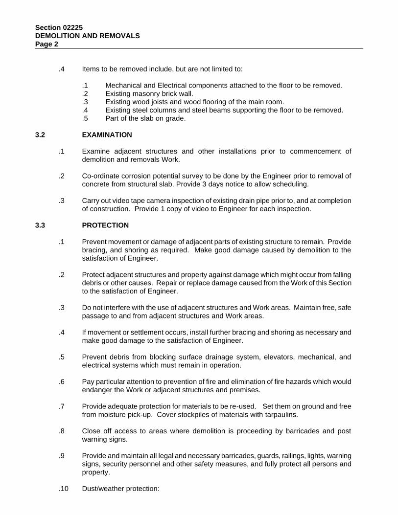
Section 02225 DEMOLITION AND REMOVALS Page 2
.4 Items to be removed include, but are not limited to: .1 Mechanical and Electrical components attached to the floor to be removed. .2 Existing masonry brick wall. .3 Existing wood joists and wood flooring of the main room. .4 Existing steel columns and steel beams supporting the floor to be removed. .5 Part of the slab on grade.
3.2 EXAMINATION
.1 Examine adjacent structures and other installations prior to commencement of demolition and removals Work.
.2 Co-ordinate corrosion potential survey to be done by the Engineer prior to removal of
concrete from structural slab. Provide 3 days notice to allow scheduling.
.3 Carry out video tape camera inspection of existing drain pipe prior to, and at completion of construction. Provide 1 copy of video to Engineer for each inspection.
3.3 PROTECTION
.1 Prevent movement or damage of adjacent parts of existing structure to remain. Provide bracing, and shoring as required. Make good damage caused by demolition to the satisfaction of Engineer.
.2 Protect adjacent structures and property against damage which might occur from falling
debris or other causes. Repair or replace damage caused from the Work of this Section to the satisfaction of Engineer.
.3 Do not interfere with the use of adjacent structures and Work areas. Maintain free, safe
passage to and from adjacent structures and Work areas.
.4 If movement or settlement occurs, install further bracing and shoring as necessary and make good damage to the satisfaction of Engineer.
.5 Prevent debris from blocking surface drainage system, elevators, mechanical, and
electrical systems which must remain in operation.
.6 Pay particular attention to prevention of fire and elimination of fire hazards which would endanger the Work or adjacent structures and premises.
.7 Provide adequate protection for materials to be re-used. Set them on ground and free
from moisture pick-up. Cover stockpiles of materials with tarpaulins.
.8 Close off access to areas where demolition is proceeding by barricades and post warning signs.
.9 Provide and maintain all legal and necessary barricades, guards, railings, lights, warning
signs, security personnel and other safety measures, and fully protect all persons and property.
.10 Dust/weather protection:
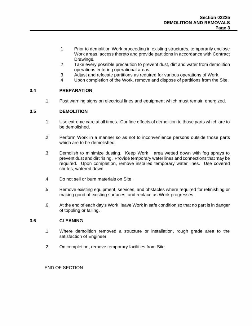
Section 02225 DEMOLITION AND REMOVALS Page 3
.1 Prior to demolition Work proceeding in existing structures, temporarily enclose
Work areas, access thereto and provide partitions in accordance with Contract Drawings.
.2 Take every possible precaution to prevent dust, dirt and water from demolition operations entering operational areas.
.3 Adjust and relocate partitions as required for various operations of Work.
.4 Upon completion of the Work, remove and dispose of partitions from the Site. 3.4 PREPARATION
.1 Post warning signs on electrical lines and equipment which must remain energized. 3.5 DEMOLITION
.1 Use extreme care at all times. Confine effects of demolition to those parts which are to be demolished.
.2 Perform Work in a manner so as not to inconvenience persons outside those parts
which are to be demolished.
.3 Demolish to minimize dusting. Keep Work area wetted down with fog sprays to prevent dust and dirt rising. Provide temporary water lines and connections that may be required. Upon completion, remove installed temporary water lines. Use covered chutes, watered down.
.4 Do not sell or burn materials on Site. .5 Remove existing equipment, services, and obstacles where required for refinishing or
making good of existing surfaces, and replace as Work progresses.
.6 At the end of each day's Work, leave Work in safe condition so that no part is in danger of toppling or falling.
3.6 CLEANING
.1 Where demolition removed a structure or installation, rough grade area to the satisfaction of Engineer.
.2 On completion, remove temporary facilities from Site.
END OF SECTION

Section 02250 TEMPORARY SHORING Page 1
1 General 1.1 SECTION INCLUDES
.1 Labour, Products, equipment and services necessary for the installation of temporary shoring and in accordance with the Contract Documents.
.2 Design, provide, install and maintain all shoring necessary to safely support the slab or
walls of the structure as shown on Contract Drawings and as required to prevent movements, loss of soil or other activity so that no damage occurs to the structure and adjacent structures and/or services. Maintain shoring in position until the repairs to the structural slab have been carried out and as directed by the Engineer.
1.2 REFERENCED STANDARDS
.1 CAN/CSA-S16.1 Design of Steel Structures, Limit States.
.2 CSA W59 Welded Steel Construction (Metal Arc Welding).
.3 CSA W47.1 Certification of Companies for Fusion Welding of Steel Structures.
.4 CAN/CSA-A23.1 Concrete Materials and Methods of Concrete Construction.
.5 CAN/CSA-A23.2 Methods of Test for Concrete.
.6 CISC Code of Standard Practice for Structural Steel Published by Canadian Institute of
Steel Construction. 1.3 DESIGN REQUIREMENTS
.1 Refer and conform to structural Drawings and existing Drawings.
.2 For sequencing of the Work see the structural Drawings.
.3 Design shall be carried out by a Professional Engineer registered in the Province of Ontario. The design shall be based on actual Site conditions and on the design criteria shown on the structural Drawings. Effects of surcharge loading shall be calculated in accordance with the Ontario Building Code and the Ontario Highway Bridge Design Code.
.4 Design the shoring system to limit deflection and/or movement to 6 mm maximum.
.5 The allowable stresses for the material shall conform to the Regulations of the Ontario
Building Code for normal duration of loading.
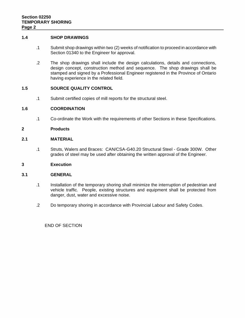
Section 02250 TEMPORARY SHORING Page 2
1.4 SHOP DRAWINGS
.1 Submit shop drawings within two (2) weeks of notification to proceed in accordance with Section 01340 to the Engineer for approval.
.2 The shop drawings shall include the design calculations, details and connections,
design concept, construction method and sequence. The shop drawings shall be stamped and signed by a Professional Engineer registered in the Province of Ontario having experience in the related field.
1.5 SOURCE QUALITY CONTROL
.1 Submit certified copies of mill reports for the structural steel. 1.6 COORDINATION
.1 Co-ordinate the Work with the requirements of other Sections in these Specifications. 2 Products 2.1 MATERIAL
.1 Struts, Walers and Braces: CAN/CSA-G40.20 Structural Steel - Grade 300W. Other grades of steel may be used after obtaining the written approval of the Engineer.
3 Execution 3.1 GENERAL
.1 Installation of the temporary shoring shall minimize the interruption of pedestrian and vehicle traffic. People, existing structures and equipment shall be protected from danger, dust, water and excessive noise.
.2 Do temporary shoring in accordance with Provincial Labour and Safety Codes.
END OF SECTION
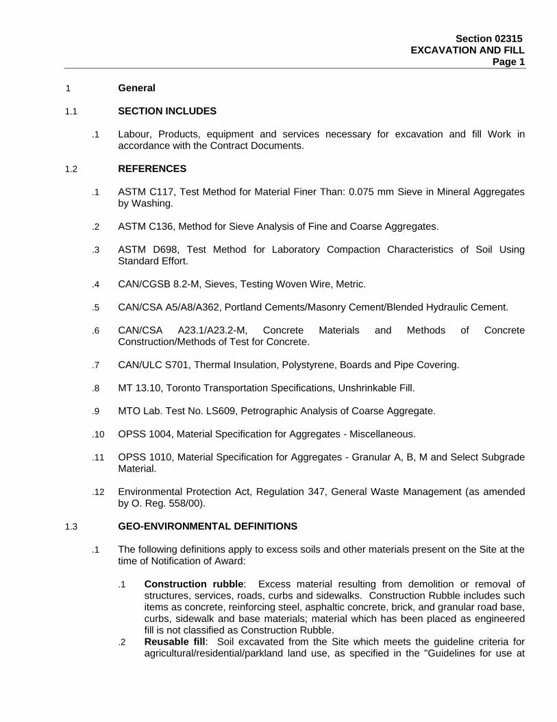
Section 02315 EXCAVATION AND FILL Page 1
1 General
1.1 SECTION INCLUDES
.1 Labour, Products, equipment and services necessary for excavation and fill Work in accordance with the Contract Documents.
1.2 REFERENCES
.1 ASTM C117, Test Method for Material Finer Than: 0.075 mm Sieve in Mineral Aggregates by Washing.
.2 ASTM C136, Method for Sieve Analysis of Fine and Coarse Aggregates.
.3 ASTM D698, Test Method for Laboratory Compaction Characteristics of Soil Using
Standard Effort.
.4 CAN/CGSB 8.2-M, Sieves, Testing Woven Wire, Metric.
.5 CAN/CSA A5/A8/A362, Portland Cements/Masonry Cement/Blended Hydraulic Cement.
.6 CAN/CSA A23.1/A23.2-M, Concrete Materials and Methods of Concrete Construction/Methods of Test for Concrete.
.7 CAN/ULC S701, Thermal Insulation, Polystyrene, Boards and Pipe Covering.
.8 MT 13.10, Toronto Transportation Specifications, Unshrinkable Fill.
.9 MTO Lab. Test No. LS609, Petrographic Analysis of Coarse Aggregate.
.10 OPSS 1004, Material Specification for Aggregates - Miscellaneous.
.11 OPSS 1010, Material Specification for Aggregates - Granular A, B, M and Select Subgrade
Material.
.12 Environmental Protection Act, Regulation 347, General Waste Management (as amended by O. Reg. 558/00).
1.3 GEO-ENVIRONMENTAL DEFINITIONS
.1 The following definitions apply to excess soils and other materials present on the Site at the time of Notification of Award:
.1 Construction rubble: Excess material resulting from demolition or removal of
structures, services, roads, curbs and sidewalks. Construction Rubble includes such items as concrete, reinforcing steel, asphaltic concrete, brick, and granular road base, curbs, sidewalk and base materials; material which has been placed as engineered fill is not classified as Construction Rubble.
.2 Reusable fill: Soil excavated from the Site which meets the guideline criteria for agricultural/residential/parkland land use, as specified in the "Guidelines for use at
Section 02315 EXCAVATION AND FILL Page 2
Contaminated Sites in Ontario" published by the Ministry of Environment (MOE), Ontario (1996, revised February 1997), and other environmental regulations.
.3 Imported fill: Fill imported to use on site which meets lakefill disposal guidelines as per the Toronto Region Conservation Authority (TRCA) criteria.
.4 Excess material: Excess soil materials resulting from construction related activities on the Site which classifies as reuseable fill for environmental management purposes.
.5 Topsoil: Surface soil that supports plant life containing considerable organic matter.
.6 Waste: Soil material which neither meets the criterion for reusable fill given above, nor is classified as construction rubble, or topsoil. Solid waste materials, are classified as waste for disposal purposes depending on the results of toxicity characteristic leaching procedure (TCLP) carried out in accordance with the Ontario Environmental Protection Act, Regulation 347 (as amended by O. Reg. 558-00), Ontario Ministry of Environment, based on the comparison of leachate test results with Schedule 4 criteria (Leachate Quality Criteria).
1.4 SUBMITTALS
.1 Submit design drawings and supporting data in accordance with Section 01340 to the Engineer for approval at least four (4) weeks prior to commencing Work.
.2 Shop drawings to include, but not be limited to, design calculations, details and
connections, design concept, construction method, sequence and the means by which existing structures, utilities and services and equipment will be protected. The shop drawings shall be stamped and signed by a Professional Engineer registered in the Province of Ontario having experience in the design and inspection of cofferdams, shoring, bracing and underpinning required to complete the Work.
.3 Submit a comprehensive plan that details the equipment to be used and procedures to be
followed during the excavation and loading for transport of excavated material. Submit the plan for review and acceptance by the Engineer 28 calendar days prior to commencing the Work.
1.5 PROJECT CONDITIONS
.1 Geotechnical conditions:
.1 Information on geotechnical conditions, and soil and groundwater management strategy are available for this Site.
.2 The Contractor is responsible for carrying out any investigation necessary to ensure that the requirements of the Contract are fulfilled in accordance with these Specifications and as shown on the Contract Drawings. The Contractor shall inform the Engineer of any intention to carry out such investigations.
.2 Relics and Antiquities:
.1 Upon discovery, report immediately to the Engineer any relics, antiquities, coins,
fossils or other articles of value or interest which are uncovered during the excavation and backfilling work or discovered elsewhere on Site. Resulting activity due to such a discovery will be considered a Contract Change by the Engineer. The Engineer will
Section 02315 EXCAVATION AND FILL Page 3
issue instructions as to their disposal and afford authorities an opportunity to recover such articles.
.3 Site Conditions:
.1 Visit the Site and determine the Work extent and nature of existing conditions. In no
circumstances will any claims against the Owner be allowed resulting from failure to ascertain the Work herein described or implied.
1.6 PROTECTION
.1 Existing buried utilities, services and structures:
.1 Size, depth and location of existing utilities, services and structures are indicated for guidance only. Completeness and accuracy are not guaranteed.
.2 Prior to commencing any excavation work, notify applicable owners or authorities, establish location and state of use of buried utilities, services and structures. Clearly mark such locations to prevent disturbance during work.
.3 Confirm locations of buried utilities and services by careful test excavations. Hand dig test excavations as necessary.
.4 Maintain and protect from damage, water, sewer, gas, electric, telephone and other utilities, services and structures encountered. Obtain permission of Engineer before moving or otherwise disturbing utilities, services or structures.
.5 Record location of in-use, maintained, re-routed and abandoned underground lines.
.2 Existing buildings and surface features:
.1 Conduct with Engineer, a condition survey of existing buildings, trees and other plants, lawns, fencing, service poles, wires, rail tracks and paving, survey bench marks and monuments which can be affected by Work.
.2 Protect existing buildings and surface features which may be affected by Work from damage while Work is in progress and repair damage resulting from Work.
.3 Temporarily cover local existing catch basins and maintenance holes to prevent entry of
earth or debris.
.4 Provide necessary hoardings, guardrails, markers, including temporary warning lights and take all other measures required to ensure that no damage or injury, is caused to persons or damage to property resulting from this Work.
.5 Protect Work of other trades or work of other contracts in progress or completed and
protect existing properties, stored Products, services and utilities from damage.
.6 Protect excavations against flooding and damage and install and maintain appropriate warning devices during construction and during time when Work is closed down for any cause.
.7 Keep access roads clear of debris and dirt resulting from the Work of this Section to the
satisfaction of the authorities having jurisdiction.
Section 02315 EXCAVATION AND FILL Page 4
.8 For excavation within public roadways, erect barricades to control traffic, and make good such excavations, roads and sidewalks in accordance with requirements of authorities having jurisdiction.
1.7 QUALITY ASSURANCE
.1 Testing:
.1 Compaction testing will be performed by the Engineer on a regular basis during backfilling and compacting operations. Afford the Engineer time, space and facilities for performing these tests. In the event that poorly graded material has been placed or has been improperly compacted, or the subgrade has been improperly compacted, the Engineer reserves the right to require the removal of as much of the material as deemed necessary and to have the area recompacted after replacement of suitable acceptable material at no cost to the Owner. In addition, the Contractor may be required to excavate test pits of varying depths to allow the Engineer to carry out additional tests at no cost to the Owner.
.2 Cooperate with and assist the Engineer during inspections and tests.
.3 Remove defective materials and completed Work which fails tests and replace as directed by Engineer at no cost to the Owner.
.4 Where Work or materials fail to meet strength requirements and/or quality as indicated by test results, pay costs of additional inspection and testing required for new replacement Work or materials.
.5 Perform any additional testing by a testing laboratory acceptable to the Engineer, at no cost to the Owner.
.2 Source approval:
.1 Inform Engineer of proposed source of aggregates and imported fill, and provide
access for sampling and testing of quality of material at least four (4) weeks prior to commencing production.
.2 Source of materials to be incorporated into Work or stockpiled requires Engineer's approval.
.3 Submit laboratory test results for samples of specified fill to be supplied by this Section. Submit with proposed source of imported fill, analytical chemistry analysis of representative samples of the fill that determine the concentrations of the chemical parameters contained in the Toronto Region Conservation Authority (TRCA) lakefill criteria for open water disposal.
.4 If, in the opinion of the Engineer, materials from the proposed source do not meet, or cannot reasonably be processed to meet, specified requirements, locate an alternative source or demonstrate that the material from the source in question can be processed to meet specified requirements at no cost to the Owner.
.5 Should a change of materials source be proposed during Work, advise Engineer two (2) weeks in advance of proposed change to allow sampling and testing.
.6 Acceptance of a material at source does not preclude future rejection if it is subsequently found to lack uniformity, or if it fails to conform to requirements specified, or if its field performance is found to be unsatisfactory. Removal and disposal of all rejected material shall be at the Contractor's expense.
.3 Production sampling:
Section 02315 EXCAVATION AND FILL Page 5
.1 Products shall be subject to continual sampling by the Engineer during production.
.2 Provide the Engineer with ready access to source and processed material for purpose of sampling and testing.
.3 If materials fail to meet Specifications, bear the cost of additional sampling and testing of aggregates.
.4 Provide the necessary personnel and equipment to permit adequate investigation and sampling. Advise the Engineer at least two (2) weeks in advance of the use of any material, to allow sufficient time for sampling and testing.
.5 Final acceptance of materials will only be made after the materials have been dumped, spread and compacted in place. Rejection by the Engineer can be made at the source, on the transportation vehicle or in place. Removal and disposal of rejected material shall be at the Contractor's expense.
2 Products
2.1 MATERIALS
.1 General:
.1 Ensure fill material does not exceed the petrographic number MTO Lab. Test No. LS609 given below:
Type of Fill Petrographic Number Granular A Fill 200
.2 Granular A Fill:
.1 Granular A Fill shall be crushed aggregates from natural materials free of organic matter and in accordance with OPSS 1010 and as specified below.
.2 Gradation requirements are: Sieve Size % Passing by Weight 26.5 mm 100 19.0 mm 85 - 100 13.2 mm 65 - 90 9.5 mm 50 - 73 4.75 mm 35 - 55 1.18 mm 15 - 40 0.300 mm 5 - 22 0.075 mm 2 - 8
.3 Lean Concrete (Unshrikable Fill): For specification refer to Section 03300. 3 Execution
3.1 GASES
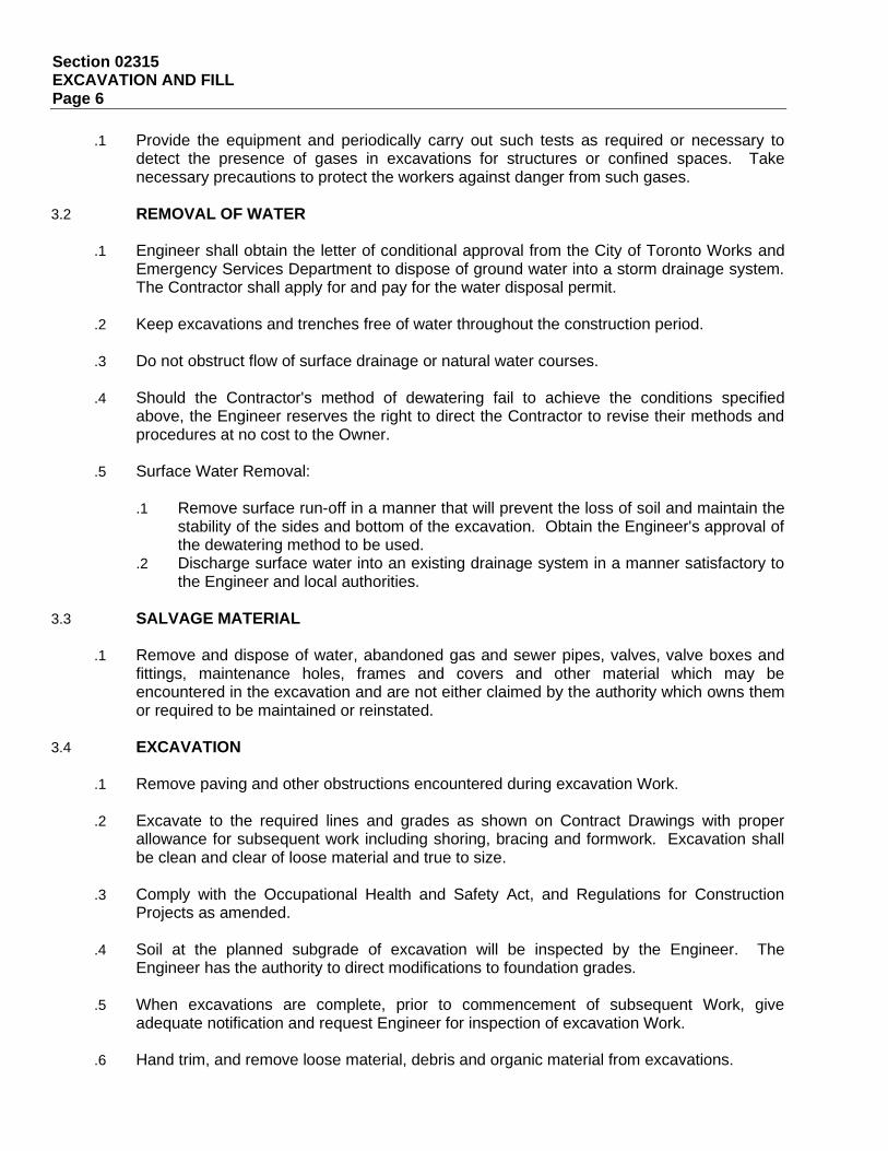
Section 02315 EXCAVATION AND FILL Page 6
.1 Provide the equipment and periodically carry out such tests as required or necessary to detect the presence of gases in excavations for structures or confined spaces. Take necessary precautions to protect the workers against danger from such gases.
3.2 REMOVAL OF WATER
.1 Engineer shall obtain the letter of conditional approval from the City of Toronto Works and Emergency Services Department to dispose of ground water into a storm drainage system. The Contractor shall apply for and pay for the water disposal permit.
.2 Keep excavations and trenches free of water throughout the construction period.
.3 Do not obstruct flow of surface drainage or natural water courses.
.4 Should the Contractor's method of dewatering fail to achieve the conditions specified
above, the Engineer reserves the right to direct the Contractor to revise their methods and procedures at no cost to the Owner.
.5 Surface Water Removal:
.1 Remove surface run-off in a manner that will prevent the loss of soil and maintain the
stability of the sides and bottom of the excavation. Obtain the Engineer's approval of the dewatering method to be used.
.2 Discharge surface water into an existing drainage system in a manner satisfactory to the Engineer and local authorities.
3.3 SALVAGE MATERIAL
.1 Remove and dispose of water, abandoned gas and sewer pipes, valves, valve boxes and fittings, maintenance holes, frames and covers and other material which may be encountered in the excavation and are not either claimed by the authority which owns them or required to be maintained or reinstated.
3.4 EXCAVATION
.1 Remove paving and other obstructions encountered during excavation Work.
.2 Excavate to the required lines and grades as shown on Contract Drawings with proper allowance for subsequent work including shoring, bracing and formwork. Excavation shall be clean and clear of loose material and true to size.
.3 Comply with the Occupational Health and Safety Act, and Regulations for Construction
Projects as amended.
.4 Soil at the planned subgrade of excavation will be inspected by the Engineer. The Engineer has the authority to direct modifications to foundation grades.
.5 When excavations are complete, prior to commencement of subsequent Work, give
adequate notification and request Engineer for inspection of excavation Work.
.6 Hand trim, and remove loose material, debris and organic material from excavations.
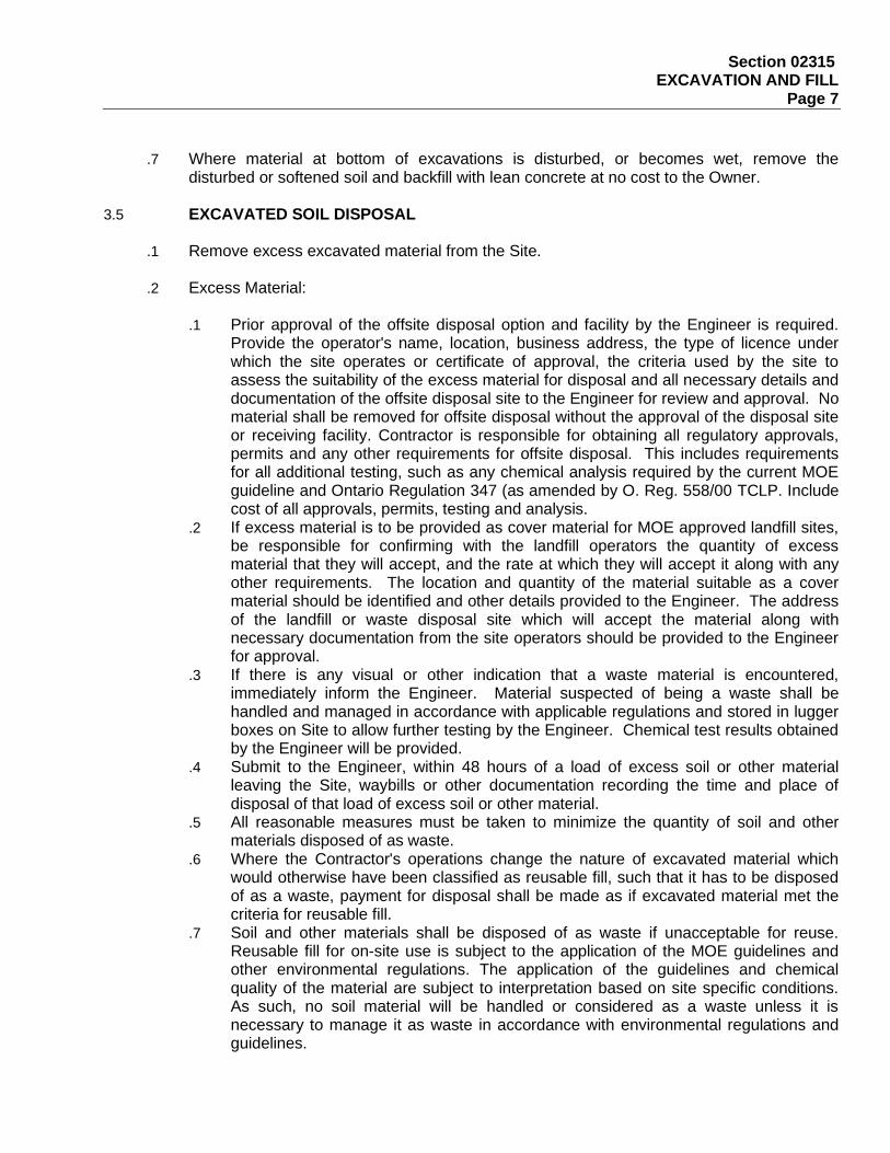
Section 02315 EXCAVATION AND FILL Page 7
.7 Where material at bottom of excavations is disturbed, or becomes wet, remove the
disturbed or softened soil and backfill with lean concrete at no cost to the Owner.
3.5 EXCAVATED SOIL DISPOSAL
.1 Remove excess excavated material from the Site.
.2 Excess Material:
.1 Prior approval of the offsite disposal option and facility by the Engineer is required. Provide the operator's name, location, business address, the type of licence under which the site operates or certificate of approval, the criteria used by the site to assess the suitability of the excess material for disposal and all necessary details and documentation of the offsite disposal site to the Engineer for review and approval. No material shall be removed for offsite disposal without the approval of the disposal site or receiving facility. Contractor is responsible for obtaining all regulatory approvals, permits and any other requirements for offsite disposal. This includes requirements for all additional testing, such as any chemical analysis required by the current MOE guideline and Ontario Regulation 347 (as amended by O. Reg. 558/00 TCLP. Include cost of all approvals, permits, testing and analysis.
.2 If excess material is to be provided as cover material for MOE approved landfill sites, be responsible for confirming with the landfill operators the quantity of excess material that they will accept, and the rate at which they will accept it along with any other requirements. The location and quantity of the material suitable as a cover material should be identified and other details provided to the Engineer. The address of the landfill or waste disposal site which will accept the material along with necessary documentation from the site operators should be provided to the Engineer for approval.
.3 If there is any visual or other indication that a waste material is encountered, immediately inform the Engineer. Material suspected of being a waste shall be handled and managed in accordance with applicable regulations and stored in lugger boxes on Site to allow further testing by the Engineer. Chemical test results obtained by the Engineer will be provided.
.4 Submit to the Engineer, within 48 hours of a load of excess soil or other material leaving the Site, waybills or other documentation recording the time and place of disposal of that load of excess soil or other material.
.5 All reasonable measures must be taken to minimize the quantity of soil and other materials disposed of as waste.
.6 Where the Contractor's operations change the nature of excavated material which would otherwise have been classified as reusable fill, such that it has to be disposed of as a waste, payment for disposal shall be made as if excavated material met the criteria for reusable fill.
.7 Soil and other materials shall be disposed of as waste if unacceptable for reuse. Reusable fill for on-site use is subject to the application of the MOE guidelines and other environmental regulations. The application of the guidelines and chemical quality of the material are subject to interpretation based on site specific conditions. As such, no soil material will be handled or considered as a waste unless it is necessary to manage it as waste in accordance with environmental regulations and guidelines.
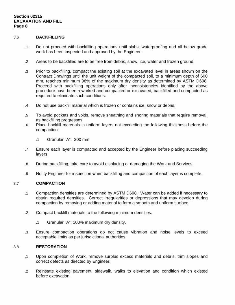
Section 02315 EXCAVATION AND FILL Page 8
3.6 BACKFILLING
.1 Do not proceed with backfilling operations until slabs, waterproofing and all below grade work has been inspected and approved by the Engineer.
.2 Areas to be backfilled are to be free from debris, snow, ice, water and frozen ground.
.3 Prior to backfilling, compact the existing soil at the excavated level in areas shown on the
Contract Drawings until the unit weight of the compacted soil, to a minimum depth of 600 mm, reaches minimum 98% of the maximum dry density as determined by ASTM D698. Proceed with backfilling operations only after inconsistencies identified by the above procedure have been reworked and compacted or excavated, backfilled and compacted as required to eliminate such conditions.
.4 Do not use backfill material which is frozen or contains ice, snow or debris.
.5 To avoid pockets and voids, remove sheathing and shoring materials that require removal,
as backfilling progresses. .6 Place backfill materials in uniform layers not exceeding the following thickness before the
compaction:
.1 Granular "A": 200 mm
.7 Ensure each layer is compacted and accepted by the Engineer before placing succeeding layers.
.8 During backfilling, take care to avoid displacing or damaging the Work and Services.
.9 Notify Engineer for inspection when backfilling and compaction of each layer is complete.
3.7 COMPACTION
.1 Compaction densities are determined by ASTM D698. Water can be added if necessary to obtain required densities. Correct irregularities or depressions that may develop during compaction by removing or adding material to form a smooth and uniform surface.
.2 Compact backfill materials to the following minimum densities:
.1 Granular "A": 100% maximum dry density.
.3 Ensure compaction operations do not cause vibration and noise levels to exceed
acceptable limits as per jurisdictional authorities.
3.8 RESTORATION
.1 Upon completion of Work, remove surplus excess materials and debris, trim slopes and correct defects as directed by Engineer.
.2 Reinstate existing pavement, sidewalk, walks to elevation and condition which existed
before excavation.
Section 02315 EXCAVATION AND FILL Page 9
.3 Clean and reinstate areas affected by Work as directed by Engineer. END OF SECTION
Section 03100 CONCRETE FORMWORK AND FALSEWORK Page 1
1 General 1.1 SECTION INCLUDES
.1 Labour, Products, equipment and services necessary for Concrete Formwork and Falsework Work in accordance with the Contract Documents.
1.2 REFERENCES
.1 ACI Standard 347, Recommended Practice for Concrete Formwork.
.2 Canadian Wood Council, Wood Reference Handbook.
.3 CAN/CSA A23.1/A23.2-M, Concrete Materials and Methods of Concrete Construction/ Methods of Test for Concrete.
.4 CAN/CSA G40.20/G40.21-M, General Requirements for Rolled and Welded Structural
Quality Steel/Structural Quality Steels.
.5 CAN/CSA S269.3-M, Concrete Formwork.
.6 CSA O121-M, Douglas Fir Plywood. 1.3 DESIGN REQUIREMENTS
.1 Be responsible for design and engineering of falsework and formwork including shoring and bracing to resist loads due to wet concrete, forms, wind, and forces arising from the use of equipment to place concrete without any differential settlement between them and to ensure finished concrete is within specified tolerances.
1.4 QUALITY ASSURANCE
.1 Tolerances: Construct forms to produce plumb, level and true concrete. Maximum variations (not accumulative) shall conform to the following:
.1 For Site placed concrete not listed above, tolerances shall be in accordance with
ACI Standard 347.
.2 A variation permitted by the Engineer in one part of the construction or in other parts of the Specifications is not to be construed as permitting violation of more stringent requirements for any other part of the construction, or in any other parts of the Specifications.
1.5 DELIVERY, STORAGE AND HANDLING
.1 Store materials on Site in a manner to prevent damage. Protect from the weather. Comply with CAN/CSA A23.1-M.

Section 03100 CONCRETE FORMWORK AND FALSEWORK Page 2
.2 Protect Work of this Section from damage. Protect other Work from damage resulting from this Work. Replace damaged Work which cannot be satisfactorily repaired.
2 Products 2.1 MATERIALS
.1 Forms:
.1 Plywood: new Douglas Fir plywood conforming to CSA O121-M, G1S, in sheets as large as practical, minimum 19 mm thick, seven ply, exterior grade, manufactured with waterproof glue, edges sealed with oil based sealer.
.2 Form ties: removable or snap-off water resistant ties, fixed or adjustable length, free of
devices leaving holes in concrete larger than 25 mm in diameter, formed to break 25 mm from surface of concrete after form removal and a minimum working strength of 13 kN. Do not use wire ties.
.3 Form release agent: chemically active, non-staining release agents containing
compounds that react with the free lime present in concrete to provide water insoluble soaps, preventing concrete from sticking to forms.
.4 Form tape: pressure sensitive plastic form tape.
.5 Chamfer strips: 25 mm x 25 mm triangular fillets milled from clear, straight grain pine,
surfaced each side, or extruded vinyl type, with or without nailing flange. 3 Execution 3.1 ERECTION
.1 Verify lines and levels before proceeding with falsework and formwork.
.2 Construct falsework in accordance with CSA S269.1.
.3 Construct formwork in accordance with CAN/CSA S269.3-M to produce finished concrete conforming to shape, dimensions, locations and elevations indicated with tolerances specified herein.
.4 Obtain Engineer's acceptance for use of earth forms.
.5 Obtain Engineer's permission before framing openings not indicated on Contract
Drawings.
.6 Use form tape on inside of forms to ensure that form joints are sufficiently smooth and tight to prevent leakage.
Section 03100 CONCRETE FORMWORK AND FALSEWORK Page 3
.7 Use 25 mm chamfer strips on external corners of concrete and 25 mm fillets at interior corners of concrete members except at the following locations:
.1 Where otherwise shown on Contract Drawings. .2 Openings and recesses for Mechanical and Electrical installations. .3 Footings.
.8 Use full size form sheeting panels wherever possible. Ensure contact surfaces of
formwork produce neat and symmetrical joint patterns. Joints shall be either vertical or horizontal and, where possible, staggered to maintain structural continuity. Back vertical and horizontal joints solidly and fasten edges of abutting sheets to same stud. Take care to ensure adjacent form panels fit accurately, tight and flush. Use straight lumber.
.9 Take particular care in forming corners and openings. Ensure formwork is tight and
braced so no movement occurs.
.10 Form openings, recesses, expansion and control joints as indicated.
.11 Align form joints and make watertight. Keep form joints to a minimum. Ensure no visible defects appear on exposed finished Work.
.12 If internal ties are used, arrange them so that when forms are removed, no metal shall
be within 25 mm of any exposed surface.
.13 Internal ties will not be permitted in exposed concrete walls and in locations shown. 3.2 EMBEDDED ITEMS
.1 Install necessary pipe sleeves and wall castings and construct openings for piping.
.2 No sleeves, ducts, pipes or other openings may pass through slabs, walls, beams and columns except where acceptable to the Engineer.
.3 Install and support forms for openings, pipe sleeves, conduits, frames, castings,
anchors, and other fixtures which are to be wholly or partially embedded in concrete.
.4 Obtain approval before boxing out for bracing. Deferred setting of inserts will not be allowed.
3.3 PREPARATION OF FORMS
.1 Remove debris, sawdust and frozen matter from space to be occupied by concrete.
.2 Remove water from excavations before concrete is deposited. Divert any flow of water through proper side drains to a sump or remove by other approved methods that will avoid washing the freshly deposited concrete. Fill drains with grout after concrete has thoroughly hardened. Build bulkhead forms to ensure water stop strips project freely beyond forms and not folded back inside forms.

Section 03100 CONCRETE FORMWORK AND FALSEWORK Page 4
.3 Trim sides and bottoms and remove loose earth from earth forms before placing concrete.
.4 Clean formwork in accordance with CAN/CSA A23.1-M before placing concrete.
.5 Apply release agent by spray in accordance with manufacturer's recommendations.
Ensure form surfaces receive a uniform coating.
.6 Notify Engineer at least 2 working days prior to placing concrete to allow for inspection of formwork.
3.4 JOINTS
.1 Contraction and Expansion Joints.
.1 Form watertight contraction [and expansion] joints at locations indicated by installing waterstops and waterproofing membranes. Obtain Engineer's acceptance to install construction joints in locations other than those shown.
.2 Construction Joints:
.1 Form watertight construction joints where required and as indicated on reviewed
shop Drawings. Obtain Engineer's acceptance to install construction joints in locations other than those shown.
.2 Conform to CAN/CSA A23.1-M.
.3 Re-tighten forms before depositing new concrete on or against concrete that has set.
3.5 REMOVAL OF FORMS
.1 Do not disturb forms until concrete has hardened and developed sufficient strength to safely support its own weight and load on it.
.2 Strip formwork in accordance with CAN/CSA A23.1-M.
.3 Leave formwork in place for the following minimum periods of time after placing
concrete.
.1 Until concrete has reached 70% of its compressive strength and not before 7 days for slabs and other structural members. Re-shore concrete with adequate shoring to standards specified for 14 additional days.
.4 In hot weather, remove or loosen wood forms so concrete surfaces may be kept moist
or coated with a curing agent.
.5 In cold weather, defer removal of formwork or replace formwork with insulation blankets, to avoid thermal shock and consequent cracking of concrete surfaces.
Section 03100 CONCRETE FORMWORK AND FALSEWORK Page 5
.6 Be responsible for safety of structure, both before and after removal of forms until concrete has reached its specified 28-day compressive strength. Employ methods and sequences of removal of formwork and falsework that will permit the concrete to gradually take up stresses involved.
.7 Take particular care when removing forms to ensure no damage occurs at corners,
arises and similar locations.
.8 To help avoid colour variations in concrete, ensure length of time between concrete pouring and form removal is approximately the same for each portion of Work.
.9 When concrete is dry, install temporary polyethylene rope in reglets to prevent
contamination of same.
.10 When forms are stripped, obtain Engineer's permission before repairing voids, stone pockets, honeycombing and other defects.
.11 Re-use of formwork and falsework in concealed areas is subject to requirements of
CAN/CSA A23.1-M, CAN/CSA S269.3-M and acceptance by Engineer.
END OF SECTION
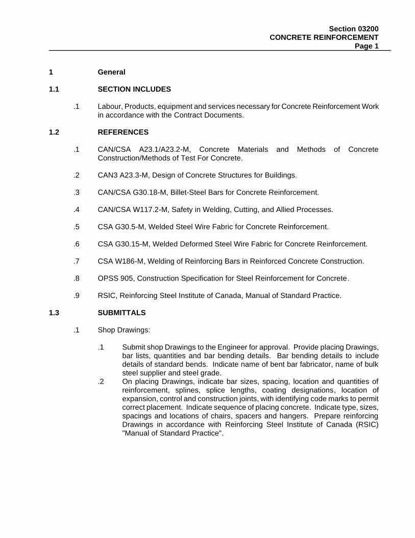
Section 03200 CONCRETE REINFORCEMENT Page 1
1 General 1.1 SECTION INCLUDES
.1 Labour, Products, equipment and services necessary for Concrete Reinforcement Work in accordance with the Contract Documents.
1.2 REFERENCES
.1 CAN/CSA A23.1/A23.2-M, Concrete Materials and Methods of Concrete Construction/Methods of Test For Concrete.
.2 CAN3 A23.3-M, Design of Concrete Structures for Buildings.
.3 CAN/CSA G30.18-M, Billet-Steel Bars for Concrete Reinforcement.
.4 CAN/CSA W117.2-M, Safety in Welding, Cutting, and Allied Processes.
.5 CSA G30.5-M, Welded Steel Wire Fabric for Concrete Reinforcement.
.6 CSA G30.15-M, Welded Deformed Steel Wire Fabric for Concrete Reinforcement.
.7 CSA W186-M, Welding of Reinforcing Bars in Reinforced Concrete Construction.
.8 OPSS 905, Construction Specification for Steel Reinforcement for Concrete.
.9 RSIC, Reinforcing Steel Institute of Canada, Manual of Standard Practice.
1.3 SUBMITTALS
.1 Shop Drawings:
.1 Submit shop Drawings to the Engineer for approval. Provide placing Drawings, bar lists, quantities and bar bending details. Bar bending details to include details of standard bends. Indicate name of bent bar fabricator, name of bulk steel supplier and steel grade.
.2 On placing Drawings, indicate bar sizes, spacing, location and quantities of reinforcement, splines, splice lengths, coating designations, location of expansion, control and construction joints, with identifying code marks to permit correct placement. Indicate sequence of placing concrete. Indicate type, sizes, spacings and locations of chairs, spacers and hangers. Prepare reinforcing Drawings in accordance with Reinforcing Steel Institute of Canada (RSIC) "Manual of Standard Practice".
Section 03200 CONCRETE REINFORCEMENT Page 2
.3 Design and detail lap lengths to CAN3 A23.3-M. Provide Type C splices unless shown otherwise. Splices are to be staggered unless otherwise shown.
.4 Show position and size of openings in walls. Co-operate with trades requiring openings to ascertain necessary information.
.5 Substitution of different size bars may be permitted upon written approval of Engineer.
.2 Testing: Submit certified copies of mill test reports for reinforcing steel and welded wire
fabric, showing physical and chemical analysis, minimum thirty (30) days prior to commencing Work.
1.4 DELIVERY, STORAGE AND HANDLING
.1 Store reinforcing steel off the ground and kept free of mud, dirt, oil and any contaminants which may adversely affect performance of the reinforcing steel. Comply with CAN/CSA A23.1-M.
.2 Store and handle reinforcing steel before, during and after placement to prevent
contamination with dust, grease, form release agents and other bond-breaking coatings.
.3 Protect Work of this Section from damage. Protect other Work from damage resulting from this Work. Replace damaged Work which cannot be satisfactorily repaired.
2 Products 2.1 MATERIALS
.1 Reinforcing steel: billet-steel bars, deformed unless indicated otherwise, Grade 400R, conforming to CAN/CSA G30.18-M
.2 Weldable reinforcing steel: weldable low alloy steel bars, deformed unless indicated
otherwise, Grade 400W, conforming to CAN/CSA G30.18-M
.3 Welded steel wire fabric: resistance welded in size and spacing shown conforming to CSA G30.5-M for smooth wire fabric and CSA G30.15-M for deformed wire fabric. Provide in flat sheets only.
.4 Cold drawn annealed steel wire ties: conforming to CSA G30.3-M, minimum 1.6 mm
diameter, complete with coating for use with uncoated and coated reinforcing steel.
.5 Chairs, bolsters, supports, spacers: conforming to CAN/CSA A23.1-M with sufficient strength to rigidly support weight of reinforcement and construction loads. Over metal deck/pan or where rust or blemishes are not acceptable use chairs, bolsters and supports with plastic tipped feet. Manufactured by NCA/Acrow - Richmond or Dayton Superior.
.6 Epoxy coated reinforcing steel: CSA G30.18M; Deformed billet steel bars, Grade 400.
Coated with epoxy in accordance with OPSS 1442 and OPSS 1443.
Section 03200 CONCRETE REINFORCEMENT Page 3
.7 Epoxy coated chairs, bolsters, supports, spacers: CAN/CSA-A23.1M with sufficient
strength to rigidly support weight of reinforcement and construction loads. Coated with epoxy in accordance with OPSS 1442 and OPSS 1443 at contact points and within 100 mm of exposed faces, or be of an acceptable non-metallic material. Manufactured by NCA/Acrow, Richmond or Dayton Superior.
.8 Only green powdered epoxy resin is acceptable.
2.2 FABRICATION
.1 Fabricate and bend reinforcing steel in accordance with CAN/CSA A23.1-M, RSIC "Manual of Standard Practice" and in accordance with reviewed placing Drawings. Fabricate and bend epoxy coated reinforcing steel in accordance with OPSS 1442 and in accordance with accepted placing drawings.
.2 Obtain Engineer's approval for locations of reinforcement splices other than those
shown on placing Drawings.
.3 Bend bars cold, heating of bars will not be permitted.
.4 Verify elevations before cutting and bending reinforcing bars.
.5 Ensure cutting and bending tolerances are sufficiently accurate to comply with placing tolerances shown.
.6 Ship bundles of bar reinforcement, clearly identified in accordance with bar bending
details and lists. Clearly indicate mill run for which bars were fabricated.
.7 Hot Dip Galvanize steel dowels with min. zinc coating of 600 g/m2 to CSA G164-71981. 3 Execution 3.1 SPLICES AND LAPS
.1 Make splices in locations shown on shop Drawings or in locations acceptable to the Engineer. Where laps are not shown on shop Drawings make each lap length as follows:
10M - 450 mm 25M - 1180 mm 15M - 630 mm 30M - 1650 mm 20M - 770 mm 35M - 2360 mm
.2 Where two bars of different diameters are lapped, use lap length of the larger bar.
.3 Lap ends and sides of wire fabric not less than 150 mm. 3.2 PLACING
Section 03200 CONCRETE REINFORCEMENT Page 4
.1 Prior to installation of reinforcing steel, carefully inspect installed Work of other trades
and verify that such Work is complete to the point where installation of reinforcing may commence.
.2 Place reinforcing steel as shown on reviewed placing Drawings and in accordance with
CAN/CSA A23.1-M. Bars shall be in lengths as long as possible.
.3 Place reinforcing steel accurately and secure with soft steel binding wire. Support reinforcing steel, with spacers, chairs or hangers, and epoxy coated reinforcing steel with epoxy coated spacers, in as close spacing as possible to prevent displacement of reinforcement from intended bar position.
.4 Tie bars at least at every fourth intersection minimum. Maximum untied length of any
bar shall be 1000 mm.
.5 Straighten kinks and bends.
.6 Do not eliminate or displace reinforcement to accommodate hardware to be embedded in concrete.
.7 Do not field bend bars partially embedded in concrete except as shown on Contract
Drawings or as authorized by Engineer.
.8 Field bending and cutting of epoxy coated reinforcing steel will not be permitted, except as shown on Contract Drawings or as authorized by the Engineer.
.9 Prior to placing concrete or closing wall and column forms, obtain Engineer's
acceptance of reinforcing steel and position. 3.3 CLEANING
.1 Ensure that reinforcing steel is free from loose mill scale, excessive rust, dirt, oil or paint.
.2 Touch-up damaged areas and cut ends of epoxy coated reinforcing steel with epoxy coating in accordance with OPSS 905 for continuous coating.
.3 Keep epoxy coating for touch-up on site.
END OF SECTION
Section 03300 CAST-IN-PLACE CONCRETE Page 1
1 General 1.1 SECTION INCLUDES
.1 Labour, Products, equipment and services necessary for Cast-In-Place Concrete Work in accordance with the Contract Documents.
1.2 REFERENCES
.2 ASTM C156, Test Method for Water Retention by Concrete Curing Materials.
.3 ASTM C309, Specification for Liquid Membrane - Forming Compounds for Curing Concrete.
.4 ASTM C494, Specification for Chemical Admixtures for Concrete.
.5 CAN/CSA A5/A8/A362, Portland Cement/Masonry Cement/Blended Hydraulic Cement
.6 CAN/CSA A23.1/A23.2-M, Concrete Materials and Methods of Concrete
Construction/Methods of Tests for Concrete.
.7 CAN/CSA A23.5-M, Supplementary Cementing Materials.
.8 CAN/CSA G30.18-M, Billet - Steel Bars for Concrete Reinforcement. 1.3 SUBMITTALS
.1 Certificates:
.1 Minimum 2 weeks prior to placement of concrete, submit to Engineer manufacturer's test data and certification by a qualified independent inspection and testing laboratory that the following materials will meet the specified requirements:
.1 Portland cement.
.2 Provide certification that plant, equipment, and materials to be used in concrete
Work comply with the requirements of CAN/CSA A23.1/A23.2-M. .3 Ready mix concrete supplier must be a member in good standing of the Ready-
Mix Concrete Association of Ontario (RMCAO). Batching plant facilities are required to maintain RMCAO special seal of quality.
.2 Construction Quality Control:
.1 Submit following proposed quality control procedures for the Engineer's
approval.
.1 Screed system to provide exact slopes required on Contract Drawings.
.3 Uniform finishes. .4 Concrete curing.
.3 Mix Design:
Section 03300 CAST-IN-PLACE CONCRETE Page 2
.1 Minimum 2 weeks prior to placement of concrete, submit mix designs to the
Engineer for trial mix testing and written approval. .2 Alkali aggregate reactivity problems may occur under certain circumstances.
Ensure mix design is adjusted suitably to prevent such problems. .3 Do not place concrete before written approval of mix is received. .4 Do not vary the approved mix without written approval. .5 Submit mix design for patching material to the Engineer for written approval.
1.4 QUALITY ASSURANCE
.1 Tolerances:
.1 Concrete in place shall be plumb, level and true. Maximum variations (not accumulative) shall conform to CAN/CSA A23.1/A23.2-M, unless noted otherwise.
.2 A variation permitted by the Engineer in one part of the construction or in one Section of the Specifications shall not be construed as permitting violation of more stringent requirements for any other part of construction, or in any other Specification Section.
.2 Inspection and Tests:
.1 Materials shall conform to CAN/CSA A23.1/A23.2-M and will be inspected and
tested for conformance to requirements of this Standard and to the Specifications by the CSE.
.2 Tests will be made in accordance with CAN/CSA A23.2-M.
.3 Co-operate with and assist the CSE's personnel during inspections and tests.
.4 Remove defective materials and completed Work which fails tests and replace as directed by the Engineer.
.5 Inspection or testing by the CSE will not augment or replace the Contractor's quality control nor relieve them of their contractual responsibility.
.3 Defective Concrete:
.1 Concrete shall be considered defective if the concrete cylinder test for any
section of Work fails to meet the specified strength. In such cases the concrete in that section may be checked by the Engineer by core specimens drilled and tested in accordance with CAN/CSA A23.2.
.2 If any core specimen has a compressive strength less than the specified strength, the Engineer has the right to require either replacement or strength-ening of the defective section of the structure. All costs, including coring, testing, strengthening, demolishing, and replacing shall be borne by the Contractor even if further evaluation of the design allows the unit to be classed acceptable.
.3 Concrete shall also be considered defective if it is structurally unsound, not watertight, honeycombed or improperly finished, as determined by the Engineer. The Engineer shall have the right to require replacement, strengthening or correction of the defective section of the structure and all such Work shall be carried out to the satisfaction of the Engineer at no cost to the Owner.
1.5 ENVIRONMENTAL REQUIREMENTS
Section 03300 CAST-IN-PLACE CONCRETE Page 3
.1 Conform to CAN/CSA A23.1/A23.2-M.
.2 Cold weather concrete placement is expected. The Contractor shall provide for all necessary means to maintain the environment around the concrete placement above 5 degree Celsius until the concrete has attained a minimum strength of 75% of the specified strength.
.3 Protection shall include, full enclosures, heating blankets, heating equipment and any necessary measures required to maintain the specified minimum temperature.
1.6 DELIVERY, STORAGE AND HANDLING
.1 Deliver and store materials on Site in accordance with CAN/CSA A23.1/A23.2-M.
.2 Concrete, Site-mixed:
.1 A structure contains more than a total of 50 m3 of concrete,
.1 Specified compressive strength is higher than 25 MPa at 28 days,
.2 Concrete is prestressed,
.3 Ready-mix concrete is specified.
.2 Concrete shall be transported from the mixer to the point of delivery as rapidly as practicable. Conform to the requirements of "Placing Concrete" Article specified herein for methods and equipment.
.3 Concrete, mixed off-Site:
.1 When a truck mixer or agitator is approved for mixing or delivery of concrete, no water from the truck-water system or elsewhere shall be added after initial introduction of mixing water to the batch, except at the start of discharge, when the measured slump of concrete is less than that specified and no more than 60 minutes has elapsed from time of batching to start of discharge. In this case, water may be added by the producer when concrete is supplied on the direction of the Engineer to a maximum amount of 10% of mix design water. Water shall not be added to the batch at any later time. Discharge of concrete shall be completed within 2 hours, after introduction of the mixing water to the cement and aggregates, or introduction of cement to aggregates. If acceptable to the Engineer, the 2 hour time limitation may be waived if concrete is of such slump that it can be placed, without addition of water, to the batch.
.2 If measured slump or entrained-air content falls outside specified limits, a check test shall be made immediately on another portion of the same sample. In the event of a second failure, the concrete shall be considered to have failed the requirements of the Specification and will be rejected.
1.7 RECORDS
.1 Before unloading at the Site, concrete producer shall provide the Engineer a delivery ticket (with each batch of concrete) on which is printed, stamped or written the following information:
.1 Name and location of batch plant; .2 Date and serial number of ticket; .3 Name of Contractor;
Section 03300 CAST-IN-PLACE CONCRETE Page 4
.4 Specific designation of job (name and location);
.5 Approved mix code, specified strength, cement content and specific class or designation of concrete indicated in " Concrete Mixes" Article specified herein;
.6 Amount of concrete in cubic meters;
.7 Truck number, cumulative total, and/or load number;
.8 Time loaded or time of first mixing of cement and aggregate.
.2 Space shall also be provided for the following information, which is to be registered by producer's representative on at least two copies of the delivery ticket, after discharge has been completed:
.1 Time that load arrived on Site; .2 Time that discharge of load was started; .3 Time that discharge of load was completed; .4 Type and amount of admixtures, if added at Site.
.3 Maintain accurate records of cast-in-place concrete elements. Records shall have the
following information:
.1 Date of placing concrete element.
.2 Location of concrete element.
.3 Specified strength of concrete.
.4 Air temperature when concrete was placed.
.5 Test samples taken and results of test samples.
.4 Additional information designated by the Engineer and required by the Specifications shall be furnished upon request.
2 Products 2.1 MATERIALS
.1 General:
1. Use admixtures for concrete from a single manufacturer, unless otherwise acceptable to the Engineer.
2. Manufacturer shall certify that all admixtures are compatible. 3. Use Products in accordance with manufacturer's recommendations unless otherwise
acceptable to the Engineer.
.2 Cement: portland to CAN/CSA-A5/A8/A362-M. Type as shown on 'Mix Data Schedule' specified herein.
.3 Ground granulated slag: conforming to 'Supplementary Cementing Materials' article of
CAN/CSA A23.5-M. Ground granulated slag may be used as a partial cement replacement up to a maximum of 25% of the volume of cement, only with the written acceptance of the Engineer.
.4 Blended hydraulic cement: CAN/CSA A362-M.
.5 Coarse aggregate:
Section 03300 CAST-IN-PLACE CONCRETE Page 5
.1 CAN/CSA A23.1/A23.2-M, tested in accordance with current MTO Petrographic Analysis Testing MTO Lab Testing Manual LS609, Los Angeles Abrasion Loss Specification MTO Lab Testing Manual LS603 and CSA Test Method CAN/CSA A23.2-16A.
.2 Petrographic number for following concretes are:
.3 .1 Concrete Pavement: 101 to maxima 125.
.4 Gradation of Coarse Aggregate: In accordance with CAN/CSA A23.1/A23.2-M Table 2, Group 1. 8 mm max. for concrete overlay, 20 mm for concrete pavements.
.6 Fine aggregate: CAN/CSA A23.1/A23.2-M.
.7 Water: CAN/CSA A23.1/A23.2-M.
.8 Water reducing admixture: ASTM C494, Type A; Euclid "WR75", Grace "WRDA 20",
Master Builders 25XL".
.9 Set retarding admixture: ASTM C494, Type D; Euclid "Retarder 75", Grace "Daratard 17", Master Builders "Pozzolith 100-XR".
.10 Air entraining admixture: CAN/CSA A23.1/A23.2-M and ASTM C260 to provide air
entrainment as shown on "Mix Data Schedule"; Euclid "Air-Extra", Grace "Daravair", Master Builders "Micro-Air".
.11 Superplasticizer (cold weather): ASTM C494, Type F; Euclid "EUCON 37", Grace
"WRDA 19", Master Builders "SPN".
.12 Superplasticizer (hot weather): ASTM C494, Type G; Euclid "EUCON 537", Grace "Daracem 100", Master Builders "Rheobuild 716".
.13 Pigmented curing compound: ASTM C309, Type 2, Class B, white pigmented resin
based; CPD "White Pigmented Curing Water Emulsion MTC Grade"; Euclid "Kurez E-40", Master Builders "Promulsion 200", Sternson's "Ritecure MTO", W.R. Meadows "1220 white pigmented".
.14 Epoxy bonding agent: Cappar "Capbond E", Master Builders "Concresive LPL", Sika
"Sika-Dur Hi-Mod", Sternson "ST-433", W.R. Meadows Resiweld 1000.
.15 Non-shrink grout: pre-mixed, flowable, non-shrink grout without aggregate fillers; Master Builders "Masterflow 713", Sternson "M-Bed OH".
.16 Anchoring for dowels: HILTI "HIT HY-150" Anchoring System.
.17 Steel dowels: CAN/CSA G30.18, Grade 400 (epoxy coated).
.18 Concrete surface hardener: Factory premixed natural emery aggregates with type 10
Normal Portland Cement, Superplasticizers and wetting agents; Emericrete SH by Sternson Ltd.; Procron EM by Master Builders Technologies.
.19 Set accelerating admixture: ASTM C494 Type C, Accelguard 80 by Euclid, Polarset by
W.R. Grace Ltd., Pozzutec 20 by Master Builders.
.20 Concrete Repair Mortar: Sikatop 123 concrete repair.
Section 03300 CAST-IN-PLACE CONCRETE Page 6
.21 Concrete Paint at Safety Nosing: IBIS MTO yellow Traffic Paint (no lead formula) as
supplied by PPG Canada.
.22 Sawcut joint sealant: Epoxy modified joint sealant, cold-applied, 2 components, pour grade, self-levelling compound with minimum Shore A Hardness of 80 and Shore D Hardness of 50:
.1 Loadflex by Sternson Ltd. .2 Bondflex by W.R. Meadows Ltd. .3 MM-80 by Metzger/McGuire.
.23 Crack Repair: Epoxy grout Sikadur by Sika Canada Inc., or reviewed alternate.
.24 Formed Joint Sealant: One component, polyurathan based, non-sag elastomeric
sealant. SikaFlex 1a by Sika Canada Inc. or approved equivalent.
.25 Building Curb and Column Caps: Two component magnesium based structural concrete, non-shrinking on cure, self-priming. MG-KRETE by JMC&B Technologies Inc. (Hamilton) or approved equivalent.
2.2 CONCRETE MIXES
.1 Produce concrete in accordance with requirements given in the following schedule and specified herein.
.2 Design concrete so that material will not segregate and excessive bleeding will not
occur.
.3 Acceptance of any concrete mix proportion or material, shall not preclude its future rejection if it is subsequently found to lack uniformity, or if it fails to conform to requirements specified, or if its field performance is found to be unsatisfactory.
.4 Ready-mixed concrete and concrete proportions shall be in accordance with CAN/CSA
A23.1/A23.2-M. Use high early strength concrete for all work at sidewalk phase.
.5 Mix concrete in accordance with CAN/CSA A23.1/A23.2-M. When combinations of Portland cement and supplementary cementing materials are used, they shall have been proven to the satisfaction of the Engineer to produce concrete to the exposure conditions outlined in the Contract Documents.
.6 Class of Exposure: In accordance with Tables 7 and 8 of CAN/CSA A23.1/A23.2-M.
Foundations, roof slabs and walls are considered Class C-1.
.7 To prevent plastic shrinkage and cracking taking place in silica fume concrete, comply with the "Curing and Protection" Article specified herein. Note that curing measures must be taken immediately after placing concrete.
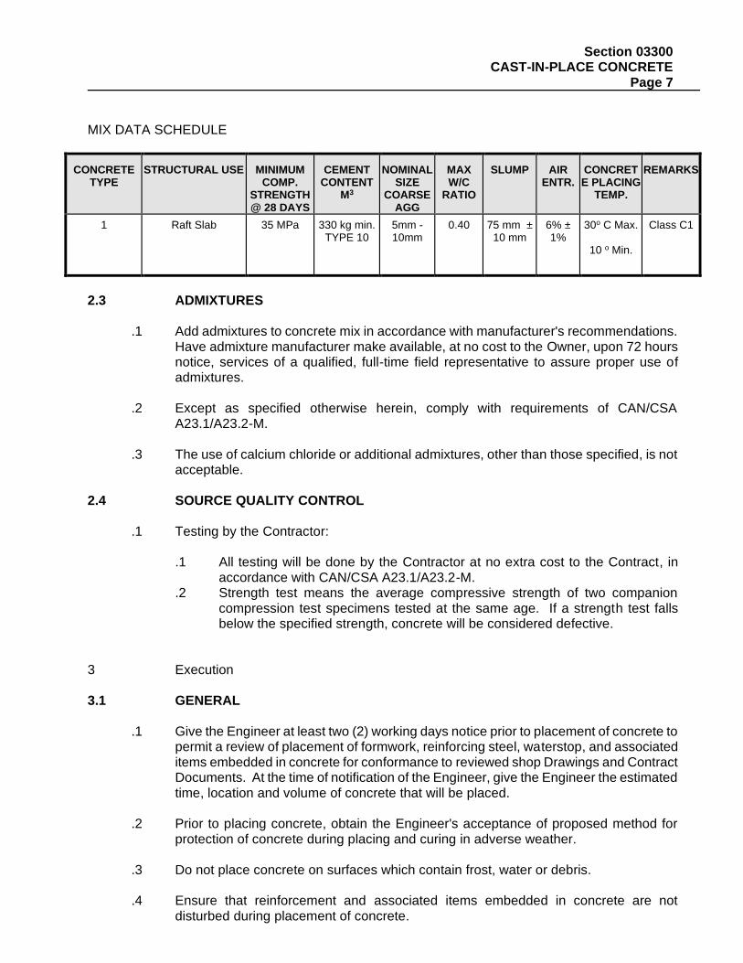
Section 03300 CAST-IN-PLACE CONCRETE Page 7
MIX DATA SCHEDULE
CONCRETE
TYPE
STRUCTURAL USE
MINIMUM
COMP. STRENGTH @ 28 DAYS
CEMENT
CONTENT M3
NOMINAL
SIZE COARSE
AGG
MAX W/C
RATIO
SLUMP
AIR
ENTR.
CONCRETE PLACING
TEMP.
REMARKS
1
Raft Slab
35 MPa
330 kg min.
TYPE 10
5mm - 10mm
0.40
75 mm ±
10 mm
6% ± 1%
30o C Max.
10 o Min.
Class C1
2.3 ADMIXTURES
.1 Add admixtures to concrete mix in accordance with manufacturer's recommendations. Have admixture manufacturer make available, at no cost to the Owner, upon 72 hours notice, services of a qualified, full-time field representative to assure proper use of admixtures.
.2 Except as specified otherwise herein, comply with requirements of CAN/CSA
A23.1/A23.2-M.
.3 The use of calcium chloride or additional admixtures, other than those specified, is not acceptable.
2.4 SOURCE QUALITY CONTROL
.1 Testing by the Contractor:
.1 All testing will be done by the Contractor at no extra cost to the Contract, in accordance with CAN/CSA A23.1/A23.2-M.
.2 Strength test means the average compressive strength of two companion compression test specimens tested at the same age. If a strength test falls below the specified strength, concrete will be considered defective.
3 Execution 3.1 GENERAL
.1 Give the Engineer at least two (2) working days notice prior to placement of concrete to permit a review of placement of formwork, reinforcing steel, waterstop, and associated items embedded in concrete for conformance to reviewed shop Drawings and Contract Documents. At the time of notification of the Engineer, give the Engineer the estimated time, location and volume of concrete that will be placed.
.2 Prior to placing concrete, obtain the Engineer's acceptance of proposed method for
protection of concrete during placing and curing in adverse weather.
.3 Do not place concrete on surfaces which contain frost, water or debris.
.4 Ensure that reinforcement and associated items embedded in concrete are not disturbed during placement of concrete.
Section 03300 CAST-IN-PLACE CONCRETE Page 8
.5 Ensure concrete cover over reinforcing steel is as indicated on Contract Drawings.
.6 Do not load new concrete until authorized by the Engineer.
3.2 INSERTS
.1 Tolerance for placing embedded items shall conform to CAN/CSA A23.1/A23.2-M, unless otherwise indicated in Contract Documents.
.2 Keep embedded items free of deleterious material.
.3 Do not eliminate, cut or displace reinforcement to accommodate hardware. If inserts
cannot be located as specified, obtain approval of modifications from the Engineer before placing concrete.
.4 As concrete is being placed, ensure that items embedded in concrete are checked from
time to time for position, alignment and elevation. Take special care to ensure a dense, watertight concrete around items set in concrete.
.5 Keep embedded items free of deleterious material.
3.3 PLACING OF CONCRETE
.1 Place concrete in accordance with CAN/CSA A23.1/A23.2-M
.2 Placing equipment, if supported by falsework or formwork, shall not impart harmful vibration to freshly placed concrete or cause any deformation or misalignment of formwork.
.3 Slope concrete to levels shown on Contract Drawings.
.4 Do not place concrete at such a rate as to endanger the formwork or to prevent proper
compaction. Cover each layer of concrete with fresh concrete within 45 minutes.
.5 Obtain approval of pneumatic or mechanical concrete placing equipment before using.
.6 Do not use pipe, hoppers, elephant trunks, placing equipment, etc. manufactured of aluminum.
.7 Place concrete to prevent cold joints and segregation and vibrate sufficiently to ensure
thorough compaction, maximum density in accordance to CAN/CSA A23.1/A23.2-M
.8 Check Work frequently with accurate instruments during placing of concrete. 3.4 CONSOLIDATING
.1 In accordance with CAN/CSA A23.1/A23.2-M
.2 Work concrete into complete contact with forms and embedded items. Consolidate concrete adjacent to side forms and along entire length of forms to ensure a smooth surface finish after stripping of formwork.

Section 03300 CAST-IN-PLACE CONCRETE Page 9
.3 Thoroughly vibrate concrete around waterstops to avoid honeycombing and voids. Ensure complete contact between waterstop and concrete. Do not use vibrators to move concrete laterally.
3.5 CURING AND PROTECTION
.1 Cure and protect concrete in accordance with CAN/CSA A23.1/A23.2-M.
.2 Protect freshly deposited concrete from the elements and from defacement due to building operations at all times and from premature drying and excessively hot and cold temperatures. Provide and use when necessary, enough tarpaulin or other suitable materials to completely cover or enclose forms and working areas during placing and curing. Have this equipment on hand and ready for use before placing is started.
.3 Cover horizontal surfaces with at least 2 layers of wet burlap or other approved
moisture-retaining covering. Do not permit intermittent drying. Provide suitable weights to prevent blow-off or displacement of burlap. Remove burlap after a minimum of 7 consecutive days and allow to air dry until concrete has developed design strengths.
3.6 CONSTRUCTION JOINTS
.1 Obtain Engineer's acceptance to install construction joints in locations other than those shown.
.2 Construct construction joints to CAN/CSA A23.1-M and as shown. Provide dowels in
construction joints unless otherwise detailed. 3.7 BONDING FRESH CONCRETE TO HARDENED CONCRETE
.1 In accordance with CAN/CSA A23.1/A23.2-M and OPSS 928.
.2 Roughen bonding surface and remove surface impurities using scarifier or shot-blaster to produce clean, rough surface.
.3 At horizontal construction joints strike off horizontal joints and float finish from reinforcing
steel to face of form. Slope concrete down slightly towards form. Ensure that the leading edge of the joint is straight and horizontal.
.4 Saturate roughened surface for 4 hours prior to concreting. Remove any standing
puddles of water.
.5 If initial clean-up is not effective, or if concrete surface has become seriously contaminated, remove deleterious layer by wet aggregate blasting immediately before placing next lift.
.6 Use at least 1.5 m3 of dried, sized sand passing the 5 mm sieve and retained on the
1.25 mm sieve for cleaning each 100 m2 of surface. After aggregate blasting wash or blow loose particles from surface of joint.
.7 Obtain the Engineer's acceptance of joint preparation before placing subsequent
concrete.
Section 03300 CAST-IN-PLACE CONCRETE Page 10
.8 Prior to placing fresh concrete apply neat cement wash consisting of 1 part latex bonding agent mixed with 2 parts Portland Cement and in accordance with manufacturers instructions.
3.8 FINISHING
.1 Treat and finish exposed formed surfaces in accordance with CAN/CSA A23.1/A23.2-M.
.2 After removal of forms, strike off projections, fill honeycombing and defects to CAN/CSA A23.1/A23.2-M. Refer to honeycombed areas for inspection and designation as structural or non-structural and repair as directed by the Engineer.
.3 Production of smooth surfaces by means of cement plaster is not permitted.
.4 Finish surface in accordance with the requirements set-out by the manufacturer of the
waterproofing system. 3.9 REPAIRING CRACKS IN CONCRETE WALLS/CURBS.
.1 Map existing cracks to receive injection repair in presence of Engineer. Place crack injection repair material using pressure grouting equipment in strict accordance with manufacturer’s written instructions.
.1 After concrete has set for 28 days, examine surfaces carefully for cracks. Rout larger
cracks at discretion of the Engineer. .2 Repair cracks with Sikadur Epoxy injection grout or approved equivalent. Installation of
grout shall by in strict conformance with the manufacturer’s specifications. 3.10 PATCHING
.1 Make good temporary openings left in concrete for pipes, conduits, ducts, shoring and other Work during construction. Reinforce with welded wire fabric as required, and finish to match surrounding Work. Carry out patching as specified in CAN/CSA A23.1/A23.2-M.
.2 Spall and delamination repairs as indicated on structural drawings with concrete repair
mortar. Finish and paint to match existing painted walls or soffit.
END OF SECTION
Section 04200 UNIT MASONRY Page 1
1 General
1.1 SECTION INCLUDES
.1 Labour, Products, equipment and services necessary for masonry Work in accordance with the Contract Documents.
1.2 REFERENCES
.1 ASTM C207, Specification for Hydrated Lime for Masonry Purposes.
.2 CAN/CSA A5/A8/A362, Portland Cement/Masonry Cement/Blended Hydraulic Cement.
.3 CAN3 A165 Series-M, CSA Standards on Concrete Masonry Units.
.4 CAN3 A370-M, Connectors for Masonry.
.5 CAN3 A371-M, Masonry Construction for Buildings.
.6 CAN3 S304-M, Masonry Design for Building.
.7 CAN/CSA A82.1-M, Burned Clay Brick (Solid Masonry Unit Made from Clay or Shale).
.8 CAN/CSA G30.3-M, Cold-drawn Steel Wire for Concrete Reinforcement.
.9 CAN/CSA G30.18-M, Billet-Steel Bars for Concrete Reinforcement.
.10 CSA A179, Mortar and Grout for Unit Masonry.
1.3 SUBMITTALS
.1 Shop drawings:
.1 Submit shop drawings in accordance with Section 01340. Verify field measurements.
.2 Indicate special detailing, patterning and locations of control and expansion joints.
.2 Samples:
.1 Submit samples in accordance with Section 01330
.2 Submit samples of each masonry unit used, prior to placing order.
.3 Submit samples of coloured mortar to match masonry samples.
.4 Submit samples of masonry anchors, and ties.
.5 Submit 250 mm long samples of backer rod and masonry sealant.
.6 Submit 250 x 200 mm samples of dampproof course and flashing.
.3 Quality control submittals:
.1 Submit manufacturer's certificates stating that materials supplied are in accordance with this Specification.
1.4 QUALITY ASSURANCE
Section 04200 UNIT MASONRY Page 2
.1 Regulatory Requirements: Supply and install plain and reinforced masonry designed in
accordance with CAN3-S304-M.
1.5 DELIVERY, STORAGE, AND HANDLING
.1 Comply with CAN3-A371-M.
.2 Keep masonry materials free from ice and frost. Keep units protected from concrete, mortar and other materials which could cause staining.
1.6 SITE CONDITIONS
.1 Do not lay masonry when ambient temperature is at or below 5 C unless temporary
protection and heating is maintained until mortar has completely set. Supply and install temporary protection and heating for installed, uncured unit masonry when ambient conditions are at, below, or are likely to go below 5 C, until 7 Days after installation.
.2 Conform to cold weather masonry requirements of CAN3-A371-M and Recommended
Practices for Cold Weather Masonry Construction by Ontario Masonry Contractors' Association.
2 Products
2.1 MATERIALS
.1 Standard concrete block units: CAN3 A165 Series-M, Classification H/15/A/M, S/15/A/M or Sc/15/A/M, [Ledge Block] [Profile Block, with 2 (3) face scores]; sizes as indicated on Contract Drawings.
.2 Lightweight concrete block units: CAN3 A165 Series- M, classification H/15/C/M, S/15/C/M
or Sc/15/C/M, sizes as indicated on Contract Drawing.
.3 Acoustical concrete block units: CAN3 A165 Series-M, Classification H/15/C/M, with slots and having a noise reduction coefficient of minimum 0.65, [modular] [ 600 mm x 300 mm x 200 mm] size.
.4 control joints, solid block where noted, concrete block lintels over openings in concrete
block walls and any additional special shapes as indicated.
.5 Obtain each masonry unit type from same manufacturer. Supply and install units of uniform texture and colour for each kind required.
.6 Supply masonry units with exposed surfaces free of cracks, chips, blemishes, and broken
corners.
.7 Reinforcing steel: CSA G30.18-M, Grade 400, refer to Contract Drawings for number, size, and location.
.8 Compressible filler: 75 x 13 mm x continuous roll; Sof-Joint Seal by Emseal Ltd.
Section 04200 UNIT MASONRY Page 3
.9 Loose steel lintels and lateral support angles: Supplied as part of Work of Section 05500.
.10 Mortar net: 250 mm high x thickness to suit cavity; Mortar Net by Mortar Net USA Ltd.
.11 Concrete fill: 20 MPa compressive strength concrete in accordance with Section 03300.
.12 Mortar for brick: CSA A179, Portland Cement - Lime Mortars Type N for exterior walls, for
interior non-load bearing walls; Type S, load bearing walls. .13 Mortar for block: CSA A179, Portland Cement - Lime Mortars, Type S for interior, and load
bearing; Type M for foundations below grade.
.14 Pointing mortar for prefaced concrete block units: [Colour: As selected by Engineer].
.15 Cement: CAN/CSA A5/A8/A362 [white] normal Portland.
.16 Hydrated lime: ASTM C207, Type S.
.17 Masonry sand: CSA A179 [white].
.18 Water: Clean potable, free from deleterious elements and free from salts that can cause efflorescence.
.19 Mortar pigment: Extra Strong Mortar Colours by Harcross Limited.
3 Execution
3.1 EXAMINATION
.1 Verify condition and dimensions of previously installed Work upon which this Section depends. Report defects to Engineer. Commencement of Work means acceptance of existing conditions.
3.2 PROTECTION
.1 Supply and install temporary waterproof, non-staining coverings, secured against displacement, to extend over walls and down sides to protect masonry Work from snow and wind driven rain, and from drying too quickly, until masonry Work completed and protected by flashings or other permanent construction.
.2 Supply and install non-staining, protective coverings on horizontal and vertical surfaces to
protect Work of this Section from damage, staining, marking, and mortar droppings.
3.3 WORKMANSHIP
.1 Perform masonry Work in accordance with CAN3 A371-M and as indicated.
.2 Supply and install masonry Work plumb, level and true to line, with vertical joints in alignment and horizontal courses level, uniform, and straight.
Section 04200 UNIT MASONRY Page 4
.3 Minimize use of cut masonry units.
.4 Distribute variations in colour, texture, and shading evenly throughout masonry Work.
3.4 MASONRY - GENERAL INSTALLATION
.1 Install masonry Work to a plane flatness and exposed end tolerance of 3 mm in 2400 mm.
.2 Do not butter corner units, throw mortar droppings into joints, or excessively furrow bed joints. Do not shift or tap units after mortar has taken initial set. If adjustment is necessary after mortar has started to set, remove and replace with fresh mortar.
.3 Do not use admixtures without Engineer's written acceptance.
.4 Tool mortar joints slightly concave with non-staining tools unless indicated otherwise and
except where waterproofing is scheduled. Strike joints flush in non exposed areas or where shown on Contract Drawings. Use sufficient force to press mortar tight against masonry units on both sides of joints. Remove excess, remaining mortar material and burrs.
.5 Install masonry walls 25 mm clear of underside of steel building frames, roof or floor deck.
[Install masonry with a 19 mm space beneath shelf angles and install compressible filler.]
.6 Cut masonry units straight with clean, even sharp unchipped edges. Cut units as required, for pattern shown, to fit adjoining Work neatly or for flush mounted electrical outlets, grilles, pipes, conduit, leaving 3 mm maximum clearance. Use full-size units without cutting wherever possible.
.7 Reinforce masonry walls with continuous masonry/cavity wall reinforcement in every
second block and every sixth brick course. In cavity veneer walls extend reinforcement from interior masonry, spanning over cavity into exterior wythe. Supply and install prefabricated L and T sections. Cut, bend and lap reinforcing units as per manufacturer's printed directions for continuity at returns, offsets, pipe enclosures, and other special conditions. Bending of masonry reinforcement or ties is not permitted.
.8 At openings supply and install extra masonry/cavity wall reinforcement, so that first and
second courses above and below openings are reinforced. Extend extra reinforcement 600 mm beyond opening in each direction.
.9 Install masonry with 10 mm thick joints unless indicated otherwise.
.10 Maintain plank in cavity and lift as Work progresses.
.11 Build control joints in masonry walls at intervals and in locations shown. Form joints using
sash block units in accordance with details shown. Fill chase and joint with joint filler full height of control joints. Leave a depth of 13 mm for sealing unless otherwise shown.
.12 Supply and install solid block or metal lath under block and fill block cells solid for lintel
bearing and as required to secure built-in anchor bolts and/or anchors as shown.
.13 Do not tooth intersections of walls except [at existing walls and] as otherwise indicated.

Section 04200 UNIT MASONRY Page 5
.14 Supply and install exterior inspection ports in cavity walls by leaving out every sixth brick (or third block) of first course over damp proof courses and flashing until wall panel supported by that course of units is constructed and reviewed. Clean cavity and obtain Engineer's review prior to filling-in inspection ports to match adjacent masonry.
.15 Install cavity vents in accordance with manufacturer's directions, in exterior wythe of
masonry above dampproof courses and flashings. Space cavity vents maximum 600 mm o.c. horizontally. Prevent cavity vents from becoming plugged with mortar or debris.
3.5 DAMPPROOF COURSES AND FLASHING
.1 Install dampproof courses beneath first masonry bearing course on slabs-on-grade and at foundation walls. Trim dampproofing to conceal it.
.2 Install flashings in masonry in accordance with CAN3 A371-M.
.3 Install flashings under exterior masonry bearing on foundation walls, slabs, shelf angles,
and steel angles over openings and elsewhere as indicated. Where flashings occur over openings in walls extend them past openings a minimum of 200 mm and turn up minimum 150 mm at each end to create a waterproof dam to prevent water draining into cavity.
.4 Lap dampproofing and flashing 150 mm and seal in accordance with manufacturer's
instructions.
.5 In cavity walls install flashings continuously from front edge of masonry, under outer wythe, turn up backing minimum 200 mm; if concrete backing, insert flashing into reglets; for masonry backing, embed flashing 25 mm in joint.
.6 At bottom of cavity install mortar net to manufacturer's instructions. Apply additional mortar
net layer as required to fill cavity. Place net in continuous layer.
.7 Before brickwork begins, place dampproofing as specified under first course of brick. Install continuous dampproofing with ends lapped and cut flush with exterior face of wall. Place similar dampproofing over top course.
3.6 MORTAR
.1 Measure and batch mortar materials either by volume or weight, to accurately control and maintain proportions. Do not measure materials by shovel.
.2 Mix mortar with maximum amount of water consistent with workability for maximum tensile
bond strength within capacity of mortar.
.3 Do not use mortar which has begun to set. Use mortar within 2 1/2 hours after initial mixing. Re-temper mortar during 2 1/2 hour period only as required to restore workability.
3.7 CONCRETE BLOCK
.1 Lay blocks in running bond except as indicated otherwise. Align block webs vertically and install thicker ends of face shells up.
Section 04200 UNIT MASONRY Page 6
.2 Install a full bed of mortar for first courses of masonry, for masonry units 100 mm thick and less, and between solid units. For remaining courses bed face shells, including vertical end joints, fully in mortar.
.3 Install special shaped and sized concrete block units as indicated and as required for a
complete and coordinated assembly and to minimize cut units.
.4 Supply and install two courses of solid block beneath lintel bearing.
.5 Stagger end joints in every course. Align joints plumb over each other in every other course.
.6 Bond intersecting block walls in alternate courses. Where blockwork abuts concrete, anchor
each block course to concrete.
.7 For veneer walls, construct inner wythe to full panel height with full joints struck flush on cavity side before proceeding with balance of cavity wall construction.
.8 Lay prefaced concrete block with a [running] [stack] bond. [Coursing height is 200 mm for
one block and one joint.] Before mortar hardens rake joint to 10 mm depth, clean block faces using soft cloths. After completion of block laying fill joints with pointing mortar, point to concave joints. Repeat cleaning of faces.
3.8 LINTELS AND LATERAL SUPPORT ANGLES
.1 Install concrete block lintels over openings in masonry except where steel lintels are indicated.
.2 Set lintels with minimum of 200 mm uniformly distributed bearing at each end.
.3 Install reinforcing steel and concrete fill in block lintels.
.4 Install loose steel lintels, as indicated in Contract Drawings. Centre over opening width.
.5 Install lateral support angles at 1200 mm o.c. along concrete block walls.
3.9 BRICK
.1 Lay brick in running bond, unless indicated otherwise, and in a full bed of mortar.
.2 Form angle corners with special shaped brick; cutting of brick is not permitted.
.3 Erect exterior cavity wall construction as shown on Contract Drawings.
.4 Install brick to prevent mortar droppings and protrusions from impeding drainage and pressure equalization of rainscreen cavities and drained walls.
.5 Apply sufficient mortar on end of stretchers to ensure end joints are compressed full when
brick is pressed into place. Install inspection port fill-in closures with fully mortared joints on all contacting sides of closure brick.

Section 04200 UNIT MASONRY Page 7
.6 Tie brick to cast-in-place concrete substrates for heights over 400 mm with masonry ties secured to cast-in-place concrete back-up at not over 300 mm o.c. vertically and 600 mm horizontally.
3.10 BUILT-IN ITEMS
.1 Coordinate and locate build-in items required to be built into masonry or supplied under Work of other Sections including hollow metal doors, frames, and screens, anchors, lintels, anchor bolts, sleeves, inserts, shelf angles, masonry flashings, etc. Build-in items to present a neat, rigid, true and plumb installation.
.2 Build wall openings, slots, and recesses required for ducts, grilles, pipes and other items.
.3 Coordinate installation of conduit, outlet boxes and other mechanical and electrical built-ins
with Work of Divisions 15 and 16.
.4 Prevent displacement of built-in items during construction. Check plumb, location and alignment frequently, as Work progresses.
.5 Brace door jambs to maintain plumbness. Set anchors between metal frames and masonry
and fill voids between hollow metal frames and masonry walls with mortar.
3.11 REPAIR AND POINTING
.1 Remove and replace masonry units which are loose, chipped, broken, cracked, marked, stained, discolored, or otherwise damaged, or if units do not match adjoining units as intended. Supply and install new units to match adjoining units and install in fresh mortar, and point to eliminate evidence of replacement.
.2 During tooling of joints, enlarge any cracks, holes, or other defects, point and completely fill
with mortar.
.3 Point-up joints including corners, openings and adjacent Work for a neat, uniform appearance, properly prepared for application of sealant compounds.
3.12 CLEANING
.1 Obtain and follow unit masonry manufacturer's written instructions for cleaning of masonry.
.2 Clean exposed, masonry surfaces, removing excess mortar as Work progresses. Dry brush installed masonry at end of each day's Work.
.3 Remove mortar with wood paddles and scrapers before wetting. Saturate masonry with
clean water and flush off loose mortar and dirt. Clean blockwork using water, scrubbing brushes and wood paddles only.
.4 Remove efflorescence in accordance with unit masonry manufacturer's written instructions,
subject to Engineer's review and acceptance of materials and methods.
.5 Clean prefaced concrete block units with a clean, soft sponge or brush and clean water; polish with soft, clean cloths.

Section 04200 UNIT MASONRY Page 8
END OF SECTION